manak bhavan, 9 bahadur shah zafar marg, new delhi …10663)_01092016.pdf · · 2016-09-01manak...
TRANSCRIPT

मानक भवन, 9 बहादरशाह फर माग, नई ददली – 110002
Manak Bhavan, 9 Bahadur Shah Zafar Marg, New Delhi – 110002
दरभाष 23231282 Website: www.bis.org.in तार: मानकसथा Phones 23230131 email: [email protected] Grams: Manaksanstha
23233375 23239402
TECHNICAL COMMITTEE: FAD 17
ADDRESSED TO:
1. All Members of Farm Irrigation and Drainage Systems Sectional Committee, FAD 17
2. Selected members of FADC
3. All interested
Dear Madam/Sir(s),
Please find enclosed the following document:
Sl. No. Doc. No. Title
1 FAD 17 (10663) C Draft Indian Standard – Agricultural irrigation equipment Filters for
microirrigation Part 2: Strainer-type filters and disc filters (Adoption
of ISO 9912-2 : 2013)
Kindly examine the draft Indian standard and forward your views stating any difficulties which you are
likely to experience in your business or profession, if this is finally adopted as Indian Standard.
Comments if any may please be made in the format attached and mailed to the undersigned at the above
address.
Last date for comments: 01 November 2016.
In case no comments are received or comments received are of editorial nature, kindly permit us to
presume your approval for the above document as finalized. However, in case of comments of technical
in nature are received then it may be finalized either in consultation with the Chairman, Sectional
Committee or referred to the Sectional Committee for further necessary action if so desired by the
Chairman, Sectional Committee.
The document is also hosted on BIS website www.bis.org.in.
Thanking you,
Yours faithfully,
(V Gopinath)
Encl: As above. Scientist ‘E’ & Head (Food & Agri) E-mail: [email protected]
________________________________________________________________________________ FOR TRAINING NEEDS, PLEASE CONTACT: NATIONAL INSTITUTE OF TRAINING FOR STANDARDIZATION
A-20&21, Institutional Area, Sector – 62, Noida – 201307. Phones : 01202402201 to 05, 4670232
Tele/Fax No. 0120-2402202-03, E-mail; [email protected] [email protected]
DOCUMENT DISPATCH ADVICE
Our Ref: Date
FAD 17/T 01–09-2016
DRAFT(S) IN WIDE
CIRCULATION

मानक भवन, 9 बहादरशाह फर माग, नई ददली – 110002
Manak Bhavan, 9 Bahadur Shah Zafar Marg, New Delhi – 110002
दरभाष 23231282 Website: www.bis.org.in तार: मानकसथा Phones 23230131 email: [email protected] Grams: Manaksanstha
23233375
23239402
तकनीक समी तत एफ ए डी 17
रषषती
1 खत म ससचाई तथा ननकासी रणाली षिषय ससमनत, एफ ए डी 17 क सम त सद य। 2 खाय एि कष षष षिभा रिरषद एफ ए डी सी क सद य । 3 चच रखन िाल सभी ननकाय ।
महोदय /महोदया, आरक अिलोकन हत नन नसलिखत मसदद सल न ह : क.स. मसौदा स या वव षय
1 एफएडी 17 (10663) सी
भारतीय मानक मसददा –– कष षष ससचाई उरकर — सम ससचाई क सलए फफटर — भा २ छना-रकार फफटर और डडक फफटर (आई एस ओ 9912-2 : 2013 स अचि षहहत)
कष रया इस रलख का अिलोकन कर अरनी स मनतय यह ततात हए भ फक यहद अतत :यह मसदद रारीय मानक क र म रकासित हो ाए तो इन रर अमल करन म आरक यिसाय अथिा कारोतार म या कहानाइया आ सकती ह । स मनतया कष रया सल न रार म अिो-ह ताीरी को भ । स मततया भजन की अततम ततथथ: 01/11/2016 यहद कोई स मनत रा त नही होती ह अथिा स मनत म किल भाषा सतिी हट हई तो उररो त रलख को यथाित अनतम र हदया ाय ा । यहद कोई स मनत तकनीक रकष नत क हई तो षिषय ससमनत क अयी क ररामि स अथिा उनक इ छा रर आ क काय िाही क सलए षिषय ससमनत को भ ान क ताद रलख को अनतम र द हदया ाय ा । ध यवाद, भवदीय
रनत: उरिरसलिखत (वी ोपीनाथ)
ि ञाननक ई एि रमख
(खाय एि कष षष षिभा ) ई-मल :[email protected]
_____________________________________ FOR TRAINING NEEDS, PLEASE CONTACT: NATIONAL INSTITUTE OF TRAINING FOR STANDARDIZATION
A-20&21, Institutional Area, Sector – 62, Noida – 201307. Phones : 01202402201 to 05, 4670232
Tele/Fax No. 0120-2402202-03, E-mail; [email protected] [email protected]
रलख रषण सञापन
सदभग ददनाक
एफ ए डी 17/टी 01-09-2016
यापक पचरलालन मसौदा

ANNEXURE
FORMAT FOR SENDING COMMENTS ON BIS DOCUMENTS
(Please use A4 size sheet of paper only and type within fields indicated. Comments on each
clauses/sub-clauses/table/fig. etc be started on a fresh box. Information in Column 4 should
include reasons for the comments and suggestions for modified wording of the clauses
when the existing text is found not acceptable. Adherence to this format facilitates
Secretariat’s work)
Doc. No.: ______________ TITLE: ________________________________________
LAST DATE OF COMMENTS: ________________
NAME OF THE COMMENTATOR/ORGANIZATION: _________________________
Sl.
No.
Clause/Subclause/
para/table/fig. no.
commented
Commentator/
Organization/
Abbreviation
Type of
Comments
(General/Editorial/
Technical)
Justification
Proposed
change

For BIS use only
DRAFT FOR COMMENTS ONLY Doc: No. FAD 17 ( 10663)C
Draft Indian Standard
कवष ससलाई उपकर — सम ससलाई क सलए फफटर — भा २ छना-रकार फफटर और डडक फफटर
Draft Indian Standard – Agricultural irrigation equipment Filters for
microirrigation Part 2: Strainer-type filters and disc filters (Adoption of ISO 9912-2 : 2013)
ICS No. 65.060.35
Not to be reproduced or used as
STANDARD without permission of BIS
Last date for comments: November 01, 2016
Farm Irrigation and Drainage Systems Sectional Committee, FAD 17
NATIONAL FOREWORD
(Adoption clause would be added later)
This Indian Standard is identical with ISO 3463: 2006 ‘Tractors for agriculture and forestry Roll-over protective
structures ROPS Dynamic test method and acceptance conditions’ issued by the International Organization for Standardization.
The text of ISO Standard has been approved as suitable for publication as an Indian Standard without deviations.
Certain conventions are, however, not identical to those used in Indian Standards. Attention is particularly drawn
to the following:
a) Wherever the words ‘International Standard’ appear referring to this standard, they should be read as
‘Indian Standard’. b) Comma (,) has been used as a decimal marker while in Indian Standards, the current practice is to use
a point (.) as the decimal marker.
In this adopted standard, reference appears to certain International standards for which Indian Standards also exist.
The corresponding Indian Standard which is to be substituted in its places, is listed below along with its degree of
equivalence for the editions indicated:
International Standard Corresponding Indian Standard Degree of
Equivalence
ISO 7-1, Pipe threads where
pressure-tight joints are made
on the threads — Part 1:
Dimensions, tolerances
and designation
IS 554 : 1999, Pipe threads where pressure-tight joints are made on the threads — Dimensions, Tolerances and Designation
Identical
ISO 7005-1, Pipe flanges — IS 6392 : 1971, Specification for Steel pipe flanges Technical Equivalent
Part 1: Steel flanges for industrial
and general service piping systems
ISO 7005-2, Metallic flanges — IS 6418 : 1971, Specification for Cast Iron and Malleable Technical Equivalent
Part 2: Cast iron flanges Cast Iron flanges for General Engineering Purposes

The technical committee responsible for the preparation of this standard may also review the following ISO
Standard and decide if this is acceptable for use in conjunction with this standard:
International Standard Title
ISO 9912-1:2004, Agricultural irrigation equipment — Filters for micro-irrigation — Part 1:
Terms, definitions and classification
In reporting the result of a test or analysis made in accordance with this standard, is to be rounded off, it shall be
done in accordance with IS 2 : 1960 ‘Rules for rounding off numerical values (revised)'. The number of significant
places retained in the rounded off value should be the same as that of the specified value in this standard.
‘FOR COMPLETE TEXT OF THE DOCUMENT, KINDLY REFER ISO ISO 9912-2 :
2013’
Note: For obtaining the hard copy of the complete document, please contact:
Scientist 'E' and Head
Food and Agriculture Department
Bureau of Indian Standards
Manak Bhavan, 9, Bahadur Shah Zafar Marg
New Delhi-110002
Telefax: 011-23231128
Email: [email protected], [email protected]

© ISO 2013
Agricultural irrigation equipment — Filters for microirrigation —
Part 2: Strainer-type filters and disc filtersMatériel agricole d’irrigation — Filtres —
Partie 2: Filtres à tamis
INTERNATIONAL STANDARD
ISO9912-2
Second edition2013-11-01
Reference numberISO 9912-2:2013(E)

ISO 9912-2:2013(E)
ii © ISO 2013 – All rights reserved
COPYRIGHT PROTECTED DOCUMENT
© ISO 2013All rights reserved. Unless otherwise specified, no part of this publication may be reproduced or utilized otherwise in any form or by any means, electronic or mechanical, including photocopying, or posting on the internet or an intranet, without prior written permission. Permission can be requested from either ISO at the address below or ISO’s member body in the country of the requester.ISO copyright officeCase postale 56 • CH-1211 Geneva 20
Tel. + 41 22 749 01 11Fax + 41 22 749 09 47E-mail [email protected] www.iso.orgPublished in Switzerland

ISO 9912-2:2013(E)
© ISO 2013 – All rights reserved iii
Contents Page
Foreword ........................................................................................................................................................................................................................................iv
1 Scope ................................................................................................................................................................................................................................. 1
2 Normative references ...................................................................................................................................................................................... 1
3 Terms and definitions ..................................................................................................................................................................................... 1
4 Marking .......................................................................................................................................................................................................................... 34.1 General ........................................................................................................................................................................................................... 3
5 Design and construction requirements ........................................................................................................................................ 45.1 General ........................................................................................................................................................................................................... 45.2 Filter housing ........................................................................................................................................................................................... 45.3 Connections ............................................................................................................................................................................................... 4
6 Mechanical and hydraulic tests ............................................................................................................................................................. 56.1 General ........................................................................................................................................................................................................... 56.2 Resistance of the filter to internal hydrostatic pressure ..................................................................................... 56.3 Filter element tightness and resistance to buckling or tearing .................................................................... 76.4 Clean pressure drop ........................................................................................................................................................................... 8
7 Information to be supplied by the manufacturer ............................................................................................................... 8
Bibliography .............................................................................................................................................................................................................................10

ISO 9912-2:2013(E)
ForewordISO (the International Organization for Standardization) is a worldwide federation of national standards bodies (ISO member bodies). The work of preparing International Standards is normally carried out through ISO technical committees. Each member body interested in a subject for which a technical committee has been established has the right to be represented on that committee. International organizations, governmental and non-governmental, in liaison with ISO, also take part in the work. ISO collaborates closely with the International Electrotechnical Commission (IEC) on all matters of electrotechnical standardization.The procedures used to develop this document and those intended for its further maintenance are described in the ISO/IEC Directives, Part 1. In particular, the different approval criteria needed for the different types of ISO documents should be noted. This document was drafted in accordance with the editorial rules of the ISO/IEC Directives, Part 2. www.iso.org/directivesAttention is drawn to the possibility that some of the elements of this document may be the subject of patent rights. ISO shall not be held responsible for identifying any or all such patent rights. Details of any patent rights identified during the development of the document will be in the Introduction and/or on the ISO list of patent declarations received. www.iso.org/patentsAny trade name used in this document is information given for the convenience of users and does not constitute an endorsement.The committee responsible for this document is ISO/TC 23, Tractors and machinery for agriculture and forestry, Subcommittee SC 18, Irrigation and drainage equipment and systems.For an explanation on the meaning of ISO specific terms and expressions related to conformity assessment, as well as information about ISO’s adherence to the WTO principles in the Technical Barriers to Trade (TBT) see the following URL: http://www.iso.org/iso/home/standards_development/resources-for-technical-work/foreword.htmThis second edition cancels and replaces the first edition (ISO 9912-2:1992), of which it constitutes a minor revision.ISO 9912 consists of the following parts, under the general title Agricultural irrigation equipment — Filters for microirrigation:
— Part 1: Terms, definitions and classification
— Part 2: Strainer-type filters and disc filters
— Part 3: Automatic flushing strainer-type filters and disc filtersA fourth part on granulated media filters is planned.
iv © ISO 2013 – All rights reserved
INTERNATIONAL STANDARD ISO 9912-2:2013(E)
Agricultural irrigation equipment — Filters for microirrigation —
Part 2: Strainer-type filters and disc filters
1 ScopeThis part of ISO 9912 specifies general construction requirements and test methods for strainer filters and disc filters (hereinafter called filters) intended for operation in agricultural irrigation systems.This part of ISO 9912 does not cover the aspects of filtration ability, efficiency, and capacity (like quality of filtered water or time of operation before a filter becomes entirely clogged), nor does it deal with structural requirements or tests of automatic flushing mechanism filters that are covered by ISO 9912-3.NOTE The parameters of filtration ability, efficiency, and capacity, their definitions, and their test methods are to be included in a separate ISO Technical Report. The test methods for comparing various filters under identical operating conditions will be described in that Technical Report, using water as defined by the client, to characterize the filter properties during operation with this water, or with water defined by the tester or the client.2 Normative referencesThe following documents, in whole or in part, are normatively referenced in this document and are indispensable for its application. For dated references, only the edition cited applies. For undated references, the latest edition of the referenced document (including any amendments) applies.ISO 7-1, Pipe threads where pressure-tight joints are made on the threads — Part 1: Dimensions, tolerances and designationISO 7005-1, Pipe flanges — Part 1: Steel flanges for industrial and general service piping systemsISO 7005-2, Metallic flanges — Part 2: Cast iron flangesISO 9912-1:2004, Agricultural irrigation equipment — Filters for micro-irrigation — Part 1: Terms, definitions and classification
3 Terms and definitionsFor the purposes of this document, the terms and definitions in ISO 9912-1 and the following apply.3.1strainer filterstrainerdevice containing one or more filter elements, such as a screen or a mesh, used for separating clogging material from water flowing through the device by collecting it on the surface of the filter element or elements[SOURCE: ISO 9912-1:2004, 2.8]3.2disc filterfilter in which the filter element is a disc filter elementNote 1 to entry: See also 3.4.
© ISO 2013 – All rights reserved 1

ISO 9912-2:2013(E)
3.3strainer filter elementfilter elementcomponent of a strainer filter consisting of a perforated plate, a screen, a mesh, or a combination of these, intended to retain clogging materials larger than a specified size from the water flowing through the component[SOURCE: ISO 9912-1:2004, 2.25]3.4disc filter elementfilter elementcomponent of a filter composed of discs with grooved or textured faces arranged adjacent to the other to form a stack
3.5filter housingcomponent of a filter that houses or supports the filter element[SOURCE: ISO 9912-1:2004, 2.34]3.6filter housing coverremovable cover permitting assembly, disassembly, inspection, and cleaning of the filter elements3.7drain valveflush valvevalve normally installed at the bottom of a filter, intended for draining or flushing of contaminate from the filter housing3.8nominal pressurepnomnumerical designation equal to the maximum working pressure specified by the manufacturer at which a device will operate at a water temperature of 23 °C ± 3 °C
3.9clean pressure droppressure drop in a clean filter, measured with a flow of clean water3.10safe maximum pressure dropmaximum allowable pressure difference, declared by the manufacturer, between inlet and outlet pressures across a filter, when the filter element has become clogged to the extent of requiring cleaning or replacement
3.11critical pressure drop before failuremaximum allowable pressure difference, declared by the manufacturer, between inlet and outlet pressures across each filtering element of the filter, which will not cause failure of the filter element3.12range of recommended flow ratesrange of flow rates, declared by the manufacturer, for proper operation of a filter3.13nominal sizenumerical designation used to refer to the size of the device end connection which is identical to the numerical designation of the pipe or pipes to which the device is to be connected directly
2 © ISO 2013 – All rights reserved

ISO 9912-2:2013(E)
3.14aperture sizesize, declared by the manufacturer, that expresses the ability of a filter to retain particles and suspended matterNote 1 to entry: The aperture size is expressed in microns.3.15filter connection lengthoverall length between the extremities of the connections of a filter, the face-to-face distance between the connections, or the distance between centre-lines of the parallel inlet and outlet ports3.16contaminatedebris, suspended particles of organic or inorganic origin, or other contaminants removed from water in the filtration process[SOURCE: ISO 9912-1:2004, 2.9]4 Marking
4.1 GeneralEach filter shall bear a readily visible, durable marking giving the particulars specified in 4.1.1 and 4.1.2.
4.1.1 Marking of filter housingThe marking of the filter housing shall include:a) the name of manufacturer and/or registered trademark,b) the model identification,c) the nominal size,d) the nominal pressure,e) an arrow indicating the direction of water flow, andf) the aperture size (optional marking, applicable when a filter is supplied with the filter element already assembled).The aperture size may be marked on an adhesive label affixed to the filter housing in a prominent position.4.1.2 Marking of filter elementThe marking of the filter element shall include:a) the name of manufacturer and/or registered trademark, andb) the aperture size.The aperture size may be indicated by a marking such as a specific colour that is defined in the manufacturer’s catalogue.
© ISO 2013 – All rights reserved 3

ISO 9912-2:2013(E)
5 Design and construction requirements
5.1 GeneralFilter parts that are in contact with water shall be made of non-toxic materials and shall be resistant to, or protected against, corrosion and other forms of degradation caused by existing working conditions and types of water and chemicals used in agricultural irrigation. The filter housing shall be resistant to environmental conditions.Components belonging to filters of the same size, type, and model, and produced by the same manufacturer, shall be interchangeable.Plastics parts of a filter that are exposed to ultraviolet (UV) radiation under normal working conditions in which the filter operates shall include additives to improve their resistance to UV radiation. Plastics parts that enclose waterways shall be opaque or shall be provided with an opaque cover that blocks all light from reaching clear waterway enclosures.The construction of the filter shall facilitate its proper installation in its intended location and position.The filter shall be designed so that, after the assembly of the filter element in the filter housing, all the water flowing through the filter flows through the filter element.5.2 Filter housingWhere the size or the configuration of a thread-connected filter housing does not allow for easy handling of it while connecting or disconnecting pipework, a boss or other means for facilitating connection and disconnection of the filter housing to and from the network shall be provided.The filter shall be designed so that contaminates accumulated on the filter element or in the filter housing do not enter the supply line when cleaning or replacing the filter element. In a manually cleaned filter, the construction of the filter element shall allow the disassembly, cleaning, and reassembly of the filter element without removal of the filter from the supply line.The filter connection length shall not deviate from the length indicated in the manufacturer’s catalogue by more than the tolerance specified in Table 1.
Table 1 — Filter length tolerance
Dimensions in millimetres
Length of filter Permissible deviationa≤400 ±2
>400 ±3
a The length tolerance is only applicable to filter housings where the axes of inlet and outlet ports are parallel.
5.3 Connections
5.3.1 Threads of a filter with threaded ends for direct connection to the supply line shall comply with ISO 7-1. Other types of threads are allowed provided that a suitable adaptor is supplied with each threaded connection, so that it complies with ISO 7-1.5.3.2 Flanged connections shall comply with ISO 7005-1 or ISO 7005-2, depending on the material from which the filter housing connection is made.5.3.3 For filters with other types of connections, the filter manufacturer shall supply or identify a commercially available adaptor to a standard thread as described in 5.3.1 or to a standard flange as described in 5.3.2.
4 © ISO 2013 – All rights reserved

ISO 9912-2:2013(E)
5.3.4 A suitable connection, such as a thread or a mechanical grooved connection (Victaulic1), for example), shall be provided on the drain valve outlet to facilitate the connection of components to provide for drainage.
6 Mechanical and hydraulic tests
6.1 GeneralPerform the following tests with water at a temperature of 23 °C ± 3 °C, unless otherwise indicated in the specific test description.Ensure that the instruments used for measuring the various parameters permit measurement to an accuracy of ± 2 % of actual values.6.2 Resistance of the filter to internal hydrostatic pressure
6.2.1 PreparationPerform the following tests on a filter with all its parts assembled for normal operation, according to the manufacturer’s instructions.Sample size should be determined by the tester or by the client.Close the filter housing cover according to the manufacturer’s instructions, including the required closure force or moment. If a specific tool is required for the closing, it shall be supplied by the manufacturer. Measure the force or the moment required for this operation.Before conducting the tests on a filter equipped with a drain valve, open and close the valve 100 times while applying a water pressure at the filter inlet equal to 0,75 × pnom. This step can be conducted on the valve alone, without the filter, by removing the valve.Close the filter outlet. Fill the filter with water by gravity. Verify that the water reaches all areas of the filter that are under pressure in normal use and that there is no entrapped air.6.2.2 Static pressure testApply hydraulic pressure at the filter inlet, raising it gradually to 1,5 × pnom; maintain this pressure for 5 min.If the seal of the filter housing cover swells or is dislodged, it may be returned to its location and the closing torque increased to achieve a positive seal. Then, reapply the required pressure for an additional 15 min and recheck the seal’s condition.The filter shall withstand the test pressure without suffering any damage or any visible permanent deformation.No signs of leakage shall appear through the filter housing, the filter housing cover seal, or the drain valve.6.2.3 Cyclic pressure test
6.2.3.1 Position the filter in a test bench as shown in Figure 1. Fill the test system with water and raise its pressure up to 1 bar.
1) This information is given for the convenience of users of this document and does not constitute an endorsement by ISO of this product.
© ISO 2013 – All rights reserved 5

ISO 9912-2:2013(E)
1 1
2
44
53 3
2
Key
1 pressurizing device2 stop valve/solenoid valve
3 drain valve
4 pressure gauge
5 filter under testFigure 1 — Cyclic pressure test bench
6.2.3.2 Apply a cyclic pressure at both the inlet and the outlet of the filter, increasing gradually from 1 bar to the nominal pressure (pnom), holding up this pressure, then decreasing gradually to 1 bar, as shown in Figure 2.
pnom
P
t
1
0
Key
t time in seconds
P pressure in bar
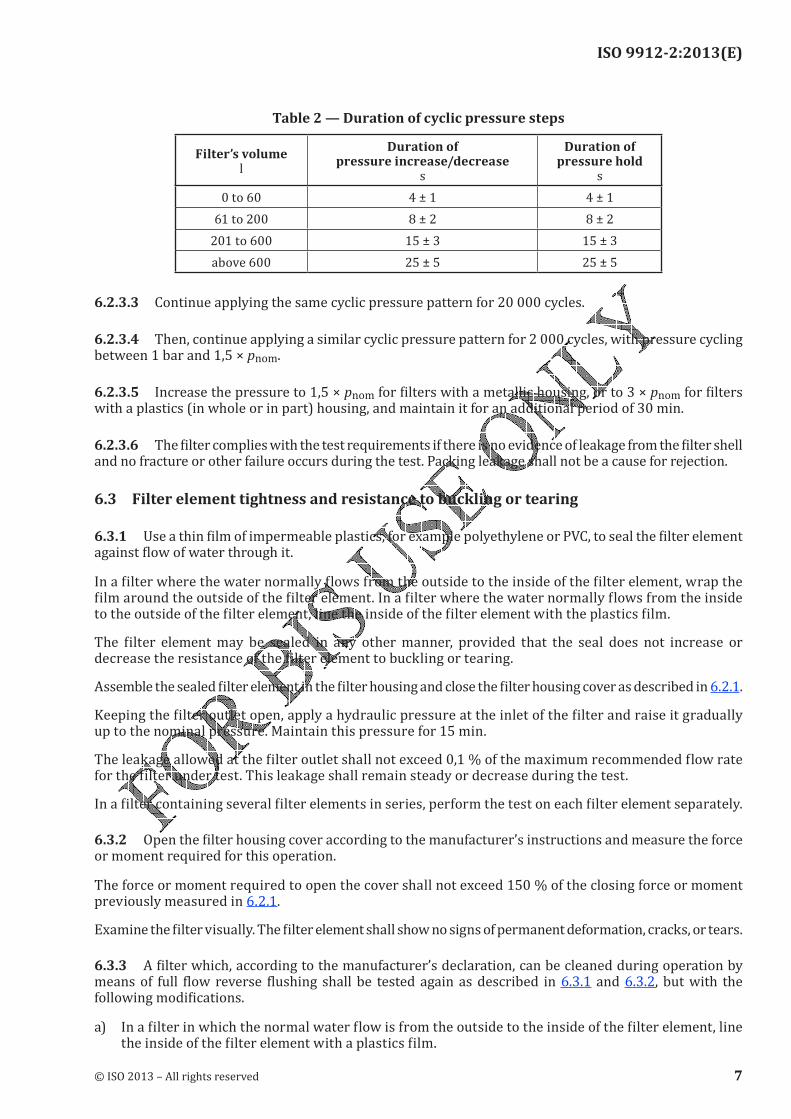
Figure 2 — Cyclic pressure sequenceThe duration of pressure increase, pressure decrease, and pressure hold periods shall be according to Table 2.
6 © ISO 2013 – All rights reserved
ISO 9912-2:2013(E)
Table 2 — Duration of cyclic pressure steps
Filter’s volume l
Duration of pressure increase/decrease
s
Duration of pressure hold
s
0 to 60 4 ± 1 4 ± 1
61 to 200 8 ± 2 8 ± 2
201 to 600 15 ± 3 15 ± 3
above 600 25 ± 5 25 ± 5
6.2.3.3 Continue applying the same cyclic pressure pattern for 20 000 cycles.6.2.3.4 Then, continue applying a similar cyclic pressure pattern for 2 000 cycles, with pressure cycling between 1 bar and 1,5 × pnom.
6.2.3.5 Increase the pressure to 1,5 × pnom for filters with a metallic housing, or to 3 × pnom for filters with a plastics (in whole or in part) housing, and maintain it for an additional period of 30 min.6.2.3.6 The filter complies with the test requirements if there is no evidence of leakage from the filter shell and no fracture or other failure occurs during the test. Packing leakage shall not be a cause for rejection.6.3 Filter element tightness and resistance to buckling or tearing
6.3.1 Use a thin film of impermeable plastics, for example polyethylene or PVC, to seal the filter element against flow of water through it.In a filter where the water normally flows from the outside to the inside of the filter element, wrap the film around the outside of the filter element. In a filter where the water normally flows from the inside to the outside of the filter element, line the inside of the filter element with the plastics film.The filter element may be sealed in any other manner, provided that the seal does not increase or decrease the resistance of the filter element to buckling or tearing.Assemble the sealed filter element in the filter housing and close the filter housing cover as described in 6.2.1.Keeping the filter outlet open, apply a hydraulic pressure at the inlet of the filter and raise it gradually up to the nominal pressure. Maintain this pressure for 15 min.The leakage allowed at the filter outlet shall not exceed 0,1 % of the maximum recommended flow rate for the filter under test. This leakage shall remain steady or decrease during the test.In a filter containing several filter elements in series, perform the test on each filter element separately.6.3.2 Open the filter housing cover according to the manufacturer’s instructions and measure the force or moment required for this operation.The force or moment required to open the cover shall not exceed 150 % of the closing force or moment previously measured in 6.2.1.Examine the filter visually. The filter element shall show no signs of permanent deformation, cracks, or tears.6.3.3 A filter which, according to the manufacturer’s declaration, can be cleaned during operation by means of full flow reverse flushing shall be tested again as described in 6.3.1 and 6.3.2, but with the following modifications.a) In a filter in which the normal water flow is from the outside to the inside of the filter element, line the inside of the filter element with a plastics film.
© ISO 2013 – All rights reserved 7

ISO 9912-2:2013(E)
b) In a filter in which the normal water flow is from the inside to the outside of the filter element, wrap the plastics film around the outside of the filter element.c) Keeping the filter inlet open, apply hydraulic pressure at the outlet of the filter and raise it gradually to a pressure equal to the critical pressure drop before failure as specified by the manufacturer.6.3.4 The test described in this subclause (6.3.4) shall only be performed on a filter in which a leakage, which exceeds the specified limits, has been observed in the test performed according to 6.3.1.Instead of the regular filter element, install in the filter a solid impermeable element identical in size and in surface smoothness to the regular filter element. Close the cover of the housing as described in 6.2.1.
Repeat the test described in 6.3.1.The leakage allowed at the filter outlet shall not exceed 0,05 % of the maximum recommended flow rate. This leakage shall remain steady or decrease during the test.In a filter containing several filter elements, perform the test on each filter element separately.6.4 Clean pressure dropMeasure the clean pressure drop of the filter for at least five different flow rates, equally distributed across the range declared by the manufacturer where one flow rate is within 10 % of the upper limit and one flow rate is within 10 % of the lower limit.Use clean water (with less than 20 ppm of particles larger than 50 % of the filter aperture size) or prefilter by passing the water through a filter element with an aperture size at least 50 % smaller than that of the filter element being tested.The measured pressure drop shall not be more than 10 % greater than the pressure drop declared by the filter manufacturer.7 Information to be supplied by the manufacturerThe following information shall be supplied by the manufacturer:a) the name of manufacturer and address of manufacturer or supplier;b) the model and catalogue number of filter;c) the filter data:1) nominal size (a single number designation is adequate if the inlet and outlet ports are the same size);
2) nominal pressure;3) critical pressure drop before failure, for each type of filter element;4) range of recommended flow rates;5) overall dimensions of filter;6) type of connections to piping network;7) filter connection length;8) aperture size;9) curve of clean pressure drop in the range of recommended flow rates;
8 © ISO 2013 – All rights reserved

ISO 9912-2:2013(E)
10) safe maximum pressure drop;
d) the housing cover closing instructions;e) the instructions for assembly, operation, cleaning, and maintenance, including the limitations and prohibitions;
f) the list of spare parts;g) the resistance to chemicals commonly used in agricultural irrigation.
© ISO 2013 – All rights reserved 9

ISO 9912-2:2013(E)
Bibliography
[1] ISO 9912-3, Agricultural irrigation equipment — Filters for microirrigation — Part 3: Automatic flushing strainer-type filters and disc filters
10 © ISO 2013 – All rights reserved


ISO 9912-2:2013(E)
© ISO 2013 – All rights reserved
ICS 65.060.35Price based on 10 pages