managing drilling risk
TRANSCRIPT
2 Oilfield Review
Walt AldredDick PlumbSugar Land, Texas, USA
Ian BradfordJohn CookVidhya GholkarCambridge, England
Liam CousinsReginald MintonBP Amoco plcAberdeen, Scotland
John FullerGatwick, England
Shuja GorayaCabinda, Angola
Dean TuckerAberdeen, Scotland
For help in preparation of this article, thanks to LaurenceCahuzac and Chin Yuin Hui, Sedco Forex, Montrouge,France; Richard Carossino and Dave Ede, Anadrill, Aberdeen,Scotland; Charles Cosad, Camco, Houston, Texas, USA;Edward Habgood, GeoQuest, Gatwick, England; and WilliamStandifird, Anadrill, Youngsville, Louisiana, USA.APWD (Annular Pressure While Drilling), ARC5 (ArrayResistivity Compensated), DrilCast, DrilMap, DrilTrack,IDEAL (Integrated Drilling Evaluation and Logging), MDT(Modular Formation Dynamics Tester), PowerPak, RFT(Repeat Formation Tester), Schlumberger PERFORM andSPIN Doctor are marks of Schlumberger.
Oil and gas companies spend about $20 billionannually on drilling. Unfortunately, not all of thatmoney is well spent. A significant portion, around15%, is attributed to losses. These include loss ofmaterial, such as drilling equipment and fluids,and loss of drilling process continuity, called non-productive time (NPT). These losses are incurredwhile searching for and implementing remediesto drilling problems. Avoiding drilling problemscuts finding and development costs and allowsbillions of dollars now spent on losses to be betterspent—building and replacing reserves.
No well is drilled without problems. Managingdrilling risk means not letting small problemsbecome big ones. Knowing what the risks are andwhen they are likely to occur keeps surprises to aminimum. Most of the time spent drilling, andmost of the cost, is encountered not in the reser-voir, but in getting to it.
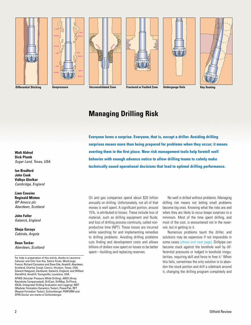
Numerous problems taunt the driller, andsolutions may be expensive if not impossible insome cases (above and next page). Drillpipe canbecome stuck against the borehole wall by dif-ferential pressures or lodged in borehole irregu-larities, requiring skill and force to free it.1 Whenthis fails, sometimes the only solution is to aban-don the stuck portion and drill a sidetrack aroundit, changing the drilling program completely and
Everyone loves a surprise. Everyone, that is, except a driller. Avoiding drilling
surprises means more than being prepared for problems when they occur; it means
averting them in the first place. New risk management tools help foretell well
behavior with enough advance notice to allow drilling teams to calmly make
technically sound operational decisions that lead to optimal drilling performance.
Managing Drilling Risk
Unconsolidated ZoneGeopressure Undergauge Hole Key SeatingDifferential Sticking Fractured or Faulted Zone

1. Bailey L, Jones T, Belaskie J, Houwen O, Jardine S,McCann D, Orban J and Sheppard M: “Causes, Detec-tion and Prevention,” Oilfield Review 3, no. 4 (October1991): 13-26.Adelung D, Askew W, Bernardini J, Campbell AT Jr.,Chaffin M, Congras G, Hensley R, Kirton B, Reese R andSparling D: “Techniques for Breaking Free,” OilfieldReview 3, no. 4 (October 1991): 27-35.Cline M, Granger G, Hache J-M and Lands J: “BackoffBasics,” Oilfield Review 3, no. 4 (October 1991): 48-51.
2. Addis T, Last N, Boulter D, Roca-Ramisa L and Plumb D: “The Quest for Borehole Stability in theCusiana Field, Colombia,” Oilfield Review 5, no. 2/3(April/July 1993): 33-43.
Summer 1999 3
potentially adding millions of dollars to the wellcost. Drilling at a high rate of penetration cansave time and money, but when accompanied bytoo low a drillstring rotation rate or mud flow ratethat fails to lift rock cuttings to surface, the resultis stuck pipe. Faults and fractures that the well-bore encounters open conduits for loss of drillingfluid to the formation.2 Excessively high mudpressure can fracture the formation and causelost circulation. Too low, and the mud pressurefails to keep high-pressure formations under con-trol, resulting in gas kicks or worse, blowouts.Drillstring vibrations can weaken and destroypipe and equipment as well as seriously damagethe wellbore. And some of these problems, evenif they don’t completely suspend the drilling pro-cess, jeopardize subsequent logging, completionand production.
Making drilling decisions to correct theseproblems is a complex process because manyfactors have to be considered. For example,increasing mud weight to control wellbore sta-bility in one interval in the well may causefracturing elsewhere. Solutions are often well- orfield-specific.
Successful drilling hinges on developing asound plan, continually updating it in light of newinformation and keeping the involved personnelinformed on a timely basis. The plan must includeprocedures to follow under normal circumstancesand methods for dealing with the most likely andmost severe problems that may be encountered.With the proper training, a well-defined drillingprocess, sufficient data and tools for interpre-tation, successfully drilling a well should be aroutine process.
>Common drilling problems.
Reactive Formation Drillstring VibrationCollapsed Casing Junk Cement-RelatedMobile Formation
Wellbore Geometry Poor Hole Cleaning

BackgroundDuring the last twenty years, the industry hascelebrated innovations in drilling practices fromthe introduction of measurements-while-drilling(MWD) and steerable motors to computerizedrigsite displays and high-resolution while-drillinglogs (above). In the early 1990s, different operatorand service companies applied the power ofmaturing while-drilling measurements to adoptnew methods of stuck-pipe avoidance and otherdrilling training programs.3 Why, ten years later,
do operating companies acknowledge that thedrilling process still needs to improve? The phys-ical forces acting on the borehole haven’tchanged. What has happened?
Two things have changed. First, explorationand production (E&P) companies have alteredtheir internal structures and reduced their workforces. Many senior, experienced hands have leftthe industry. Companies are operating with abare minimum of personnel. Experienced peoplewho remain may be specialized, and hence notsuited for the integrative role required.
Second, wells are becoming more complex.Extended-reach and horizontal wells react differ-ently to earth stresses than do vertical or low-angle wells. Drilling multilateral wells requiresextraordinary accuracy and control. Deepwaterand high-pressure, high-temperature wells offeradditional challenges. Wells are being drilled intectonically active and remote areas where theinfrastructure may be less well developed andcommunication problematic.
4 Oilfield Review
Advances in Drilling Technology
Telecointroduced
simple MWD
Baker Hughesintroduced
integrated servicesbit + motor + MWD
MultisensorMWD 1
introduced
SchlumbergerintroducedARC5 tool
First sonic toolintroduced
Schlumberger introducedIDEAL system withinstrumented motor
Sperry-Sunintroduced
LWD 2 MHz
PowerPakmotors introduced
Eastman & Smithintroduced
steerable motors
Spinning chainreplaced bypipe spinner
Offshore high-pressurehigh-temperature
(HPHT) drilling Topdrive
Partially mechanizedpipe handling
Step changein QHSE
Completely mechanized
pipe-handlingDual/Tri-Act
derrick
78 7977767574737271 80 81 82 83 84 85 86 87 88 89 90 91 92 93 94 95 96 97 98 99High-rate
mud telemetry Rotarysystems
> Time line from 1971 to 1999 showing recent advances in drilling technology.
Earth Model Well Plan
Revise Interpret Detect
Asset OfficeOnshore Drilling Team
Rigsite Schlumberger PERFORM Engineer
Drill
> Integrated drilling process. The phases of a drilling project require joint effort by the asset office and the rig, and encompassconstruction of the earth model and well plan, the actual drilling, detection and interpretation of information obtained whiledrilling, and ultimately, revision of the model.

Summer 1999 5
engineer and geologist balance the requirementsof target location, cost and drillability. Manymore factors must be incorporated into a com-plete well plan. These include casing design,completion requirements, life-of-field issues, rigsize and selection, personnel considerations,costs, cement design, liners, drillstring and BHAdesign, and availability of equipment.
The best drilling plan optimizes well locationand trajectory, but also minimizes the risk ofwellbore instability and stuck pipe, improves wellproductivity and accelerates the drilling learningprocess. The plan should flag intervals in whichgeologic risks such as pore pressure, fracturepressure and other wellbore instabilities canthreaten wellbore integrity. To achieve this, theplan must be evaluated to identify all risks beforeany action takes place.
On the rig, the well is drilled according to thedrilling plan. During drilling, information is col-lected, interpreted and fed back to the drilling pro-cess, to the well plan, or to the earth model itself.Through modification and updating, the well planbecomes a living document rather than a staticone. Drilling risks are also continually reevaluated.The process is valid for wells drilled throughout
the life of a field, but at its core remain the threeprincipal phases that govern the very existence ofa well: developing the proper plan, executing it,and learning from the ongoing process.
The earth model can be simple or complex,depending on the information available and therequirements of the well. Creating a complexearth model can require dozens of input and dataintegration steps. In short, every pertinent datasource is used, from drilling reports, logs andtests in offset wells to seismic sections, velocitycubes and structural interpretations (above).
Mechanical Earth Model
Well Plan and Performance Prognosis
FaultsFormation tops
Elasticparameters
Rock strengthprofile
Pore pressureprofile
Stressdirection
Stress profilesSv, Sh, SH
2D cross sections3D velocity cubes
Structural interpretationSeismic attribute maps
Time and depth relations
Seismic Data Drilling Data
Exploration well reportsDirectional surveys
Bit recordsTime-depth curves
Mud weightsMud logs, drilling fluids
NPT—kicks, losses, stuck pipeCorrelation with geology
Log Data
Deep resistivityGamma ray
Oriented multi-arm calipersSonic P,S
Bulk densityBorehole images
Calibration Data
Microfrac, XLOTKicks and losses
Gas and flow checksCavingsCores
RFT and MDT pressure
> A partial list of the types of data that contribute to a complex mechanical earth model.
3. Bradley WB, Jarman D, Auflick RA, Plott RS, Wood RD,Schofield TR and Cocking D: “Task Force ReducedStuck-Pipe Costs,” Oil & Gas Journal 89, no. 21 (May 27,1991): 84, 86, 88-89.Nordt DP and Stone MS: “Professional Development ofNew Rig Supervisors a Must,” Oil & Gas Journal 90, no. 43 (October 26, 1992): 77-80, 83-84.
A New ApproachTo drill successfully amid these changes andchallenges requires a new approach to thedrilling process. In recent years, oil companiesand service companies have developed morecooperative relationships that make it easier forboth to achieve their objectives. The way ofdoing business together has evolved from one ofmanaged opposition to one of aligned objectives,with oil and service companies cooperating toface the uncertainty and risks of the subsurface.
The approach taken by the Schlumberger com-panies to provide technical and decision supportto operators has reduced drilling costs by as muchas 50% in a wide variety of drilling environments.The complete process integrates the efforts of oilcompany and service company personnel at theoffice and on the rig, during all stages of wellplanning and drilling and through every phase ofa drilling project (previous page, bottom).
Simply put, the process begins in the officewith construction of an earth model. The model isthen used as part of the well planning process tocreate the best drilling plan. This is a multidisci-plinary optimization process in which the drilling

6
0.9 0.95 1.0Drilling difficulty
0 1020
3040
50
60
70
80
90
100
110
120
130
140150
160170180
N
E
S
W
Stress0 MPa 200 W N
Stress direction Sh
Sh SH SVPp
Fault?
Regionaltrend
Grainsupport
facies
Claysupport
facies
Elastic
Stratigraphy
Strength Earth Stress and Pore Pressure
Poisson’sratio
Young’smodulus
kPa
Friction angle
E
1.0
10 20 400
0 100 0 70
Structure and Stratigraphy0
Unconfinedcompressive strength
> Earth model example. The earth model houses all information on rock properties and behavior and is usedduring all phases of the life of the well, including trajectory and wellbore stability planning, bit and rate ofpenetration (ROP) selection, pore-pressure prediction, casing design, sand control and reservoir stimulation.
Oilfield Review
> Which way to drill in a South Americanfield. With rock mechanics data such asexpected stress state, pore pressure androck failure parameters from a variety ofsources, a drilling risk profile can be plotted.Red signifies risky, difficult drilling and blue is less risky and easier. The numbersaround the arc represent azimuth; travelingalong a radius is the same as taking a pathof constant azimuth. Distance from the center depicts inclination from vertical. Thecenter of the circle represents a verticalwellbore, and the outer edge represents allpossible horizontal wellbores. This plotindicates that it is easier to drill a horizontalwell than a vertical well given the particularstress state.

7
Diagnose
Develop plan
DrilMap
DrilCast
DrilTrak
Schlumberger PERFORM Workflow
No Yes
Yes
Loss No loss
Summary and detailedrisk report
24-hr activity forecastRoles and responsibilities
To drilling team
Prepare risk assessmentfor each hole section
Develop forward planand contingencies for each
hole section with drilling team
Prepare daily risk assessmentfor next 24 hr
Develop forward planand contingencies for next
24 hr with drilling team
Drilling and geologicalprogram roles and
responsibilities
ObservationsData collectionInterpretation
Analysis
Compliancewith plan?
Contingencies?
Current rigearth state
Report tocompany
representative
Eventreport
Near-missreport
No
Diagnose
Develop plan
> The Schlumberger PERFORM workflow.Responsibilities extend from risk assessment and contingency planning to data collection andanalysis, then to reporting, well plan updatingand activity forecasting. The colors in the upperleft key refer to display, reporting or analysistools described in subsequent figures.
(A full treatment of the rock mechanics involvedis beyond the scope of this article.4) The result-ing mechanical earth model consists of forma-tion tops, faults, elastic parameters, stressdirections and variations with depth, and rockstrength and pore-pressure profiles (previouspage, top).
Once a target has been selected, it can bereached from many directions. Selecting the pathwith the least risk requires an understanding ofthe stress state and the rock parameters, andhow the drilling process will interact with them.An example of the information that can beextracted from an accurate mechanical earthmodel comes from a South American field. Forthis field, a risk profile was created that color-coded the difficulty with which particular trajec-
tories could be drilled (previous page, bottom).Drilling a horizontal well at a 90° azimuth waspredicted to be the least risky: wells at otherinclinations and azimuths would be prone toborehole collapse.
The best plan according to any earth modelmust be reconciled with trajectory goals of thatwell to optimize the process as a whole. Forexample, in one well, the preferred trajectory mayhave a 62°-inclination in one section, but hydrau-lics analysis may indicate that hole-cleaningproblems at this inclination could endanger wellintegrity. Two or more sections drilled at saferangles, though seemingly more time-consuming,could optimize the overall drilling process.
Once the best plan has been formulated, fol-lowing it through at the rig can be a surprisinglychallenging feat. To accomplish this, thePerformance through Risk Management effort, orSchlumberger PERFORM initiative for short, hasbeen launched within Anadrill. SchlumbergerPERFORM efforts have already reduced NPT byas much as 40%, saving as much as $300,000 perwell. The concept is simple and most of the stepsare almost intuitive, but a structured approach isrequired for success. The approach comprises aworkflow, software tools and engineer to ensurethat the technical solutions derived in the plan-ning stage become operationally effective solu-tions to aid decisions that help avoid drillingproblems (above).
Summer 1999
4. For more: Fjaer E, Holt R, Horsrud P, Raaen A and RisnesR: Petroleum Related Rock Mechanics. New York, NewYork, USA: Elsevier Science Publishing Company, 1992. Alsen J, Charlez P, Harkness R, Last N, McLean M andPlumb R: “An Integrated Approach to Evaluating andManaging Wellbore Instability in the Cusiana FieldColombia, S. America,” paper SPE 30464, presented atthe SPE Annual Technical Conference and Exhibition,Dallas, Texas, USA, October 22-25, 1995.

The goal of the Schlumberger PERFORM engi-neer is to work with operators to significantlyreduce cost and nonproductive time through inte-gration of planning and real-time drilling solutions.A risk-management and loss-control frameworkcombines Schlumberger technical expertise andmeasurements with operator knowledge andexperience to develop operational solutions.Communications and teamwork are essential inimplementing these solutions.
The process concentrates on the follow-ing areas:• wellbore stability and fluid loss• pore-pressure analysis• stuck pipe and pipe lost in hole• drillstring failure prevention• drilling efficiency, rate of penetration
and bit optimization.
Because each well can host a distinct set ofthese problems, a specially trained engineer isassigned to each job. The quality of the person-nel can make or break the process. As generalqualifications, the engineer must have good prob-lem-solving, data-integration and communicationskills, a solid technical background in petroleumor drilling engineering, ample seniority and expe-rience with operator organizations. Technicaltraining includes Schlumberger courses ondrilling mechanics, wellbore stability, pore-pres-sure analysis, bit performance and drilling fluids.Operational problem-solving techniques andcommunication skills are sharpened throughproblem-simulation exercises. Additional trainingincludes industry-standard courses in stuck-pipeprevention and well control.
In the planning stage of a drilling project, theSchlumberger PERFORM engineer works with theoperator staff to identify potential hazards,develops methods for detecting them, and finallywith the drilling team, formulates contingenciesto complete the drilling plan. The engineer deliversa DrilMap display that links well geometry, geo-logical and hazard information with contingencyplans to form a complete process map for thewell (above).
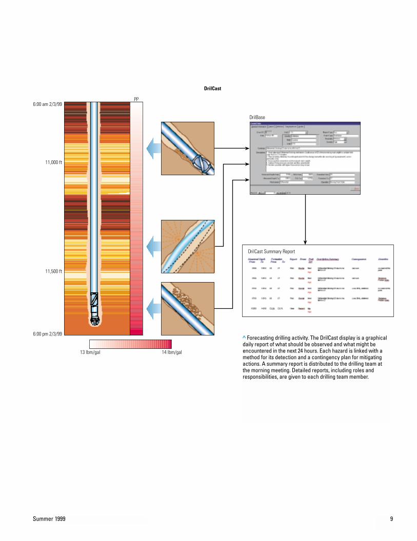
During drilling, the engineer evaluates thewell condition to identify any new hazards thatmay have developed and at every tour providesan updated risk assessment and 24-hr forecast(next page). The DrilCast report enumerates theconditions and potential hazards ahead andexplains how to detect and manage them.Detailed planning before a potential hazard isencountered and accurate identification of thehazards reduce the risks of losses and signifi-cantly improve performance.
8 Oilfield Review
500PP
DrilBase
1000
1500
2000
2500
3000
3500
4000
4500
5000
Dept
h, ft
Time
Stuck pipe at 1100 ft
BHA packoff at 1700 ft
50-bbl kick at 3200 ft
DrilMap
N
8 lbm/gal 14 lbm/gal
Hole collapseat 3700 ft
Pipe stuckat 4700 ft
> Mapping out the drilling plan. The DrilMap screen displays the planned well trajectory, expectedpore pressures (PP), and two drilling time-versus-depth curves—one optimal (blue) and the othertaking into account potential hazards (red). Hazards are identified with specific depths and tied tothe DrilBase database containing previous drilling and near-miss reports and contingency plans.
(continued on page 11)
Summer 1999 9
DrilCast
DrilCast Summary Report
13 lbm/gal 14 lbm/gal
6:00 am 2/3/99
11,000 ft
11,500 ft
6:00 pm 2/3/99
PP
DrilBase
> Forecasting drilling activity. The DrilCast display is a graphicaldaily report of what should be observed and what might beencountered in the next 24 hours. Each hazard is linked with amethod for its detection and a contingency plan for mitigatingactions. A summary report is distributed to the drilling team atthe morning meeting. Detailed reports, including roles andresponsibilities, are given to each drilling team member.

10 Oilfield Review
ClientWellSection
Date
IPM
Deepwater location.
14 3/4 X 17 1/2 Drilling Assembly
2/24/99 6:00
Client Representative
Perform Engineer
Randall Anderson
William B. Standifird
For Time Period... 2/23/99 6:00 2/24/99 6:00To24-Hour Summary
Start Time2/23/99 6:002/23/99 7:302/23/99 15:30
Rig Operation
Time Period24 hr
24 hr
When? What?
2/24/99 6:00 Drilled sand lobe at 7228 ft
Under-reamingShort trip
Drilling ahead
Variable Noteworthy Behavior
Comments
MWD SHOCKS
WOB,TQA,ECD,SPP,TFLOW,TRPM
Transverse shocks increase while reaming sands.
ECD and TQA spiking when annulus loads above under-reamer.
Under-reamed to 7038 ftHole stable, 500u B/U gas
Drilling new formation
How? Why?
24-Hour Forecast For Time Period... To2/24/99 6:00 2/25/99 6:00
This is a tough section. Depleted zone at 7375 ft is next major hazard.
1
ITEM
2
3
4
ITEM
1
2
3
4
ITEM
RIG OPERATIONS
TRENDS
EVENTS
RIG OPERATIONS
HAZARD DETECTION METHODS
PROPOSED HAZARD PREVENTION ACTION
Operation When? Possible HazardsDrilling
Drilling
DrillingBack-reaming, U/RShort TripBack-reaming
Cutting sands
Cutting sands
Pumping
Pulling up
First depleted sand at 7375 ft.Stuck pipe, lost circulation.MWD shock high when U/R hits sands.MWD shock > 22 can damage BHA quickly.ECD will spike as U/R packs off.Stuck-pipe situation.Swab formation into wellbore.Gas or fluid entering wellbore.
High
High
High
Med
High
High
High
High
Severity Probability
Identify sand locations and verify stability. 7215, 7375, 7565 and 7745. Use offset e-logs/mud logs
Monitor MWD shocks on Anadrill display.
Monitor ECD closely. Spikes are rapid and must be addressed quickly.
Monitor trip speeds (swab-surge), gain/loss and gas.
Please contact the Schlumberger PERFORM Engineer if there are any questions or transmission errors: Call Ext. 158 (rig) 3460 (town)
PERFORM Daily Report
3 Consider picking up and back-reaming until ECD stabilized. First move is in opposite direction of resistance.
4 Back-ream or pump out of hole. Circulate gas out of hole if encountered. Work tight spots and keeppulling speeds minimal.
2 Rotate during connections.Notify PERFORM Engineer. May need to adjust RPM/WOB to control vibrations and avoid BHA damage.
1 Prepare LCM and other LC systems. Keep the pipe moving. Survey at 7200, 7350 and 7800. DO NOT surveyif formation is unstable. Stuck pipe is more expensive than a GYRO in casing.Torque and Slump differential sticking or coming off slips.is first action to
> Daily report of past and future drilling activity.

Summer 1999 11
In this example from a deepwater well coordi-nated by the Schlumberger Integrated ProjectManagement (IPM) group, the daily reportincludes a summary of rig operations, trends andevents of the past 24 hours along with the fore-cast for the next day (previous page). The look-ahead portion lists four possible hazards that maybe encountered in the upcoming hole section. Thesection is ranked as a tough one, with a depletedzone ahead posing the next major hazard. Thehazards are identified according to several fac-tors: the operation (drilling, back-reaming ortripping), and the specific procedure (cutting
sands, under-reaming or pumping), underwaywhen the hazard is met; the type of hazard and its consequences; the severity; and the prob-ability. Methods for detecting each hazard arelisted, as are actions to prevent an event fromcausing loss.
A member of the drilling team monitors wellconditions continuously to determine if the wellis behaving as planned (above). If the well is notproceeding as expected, the appropriate contin-gency is identified. The driller can then follow theplan for that contingency. If none of the plannedcontingencies is appropriate, the problem is ana-lyzed, and a new action plan is developed withthe drilling team.
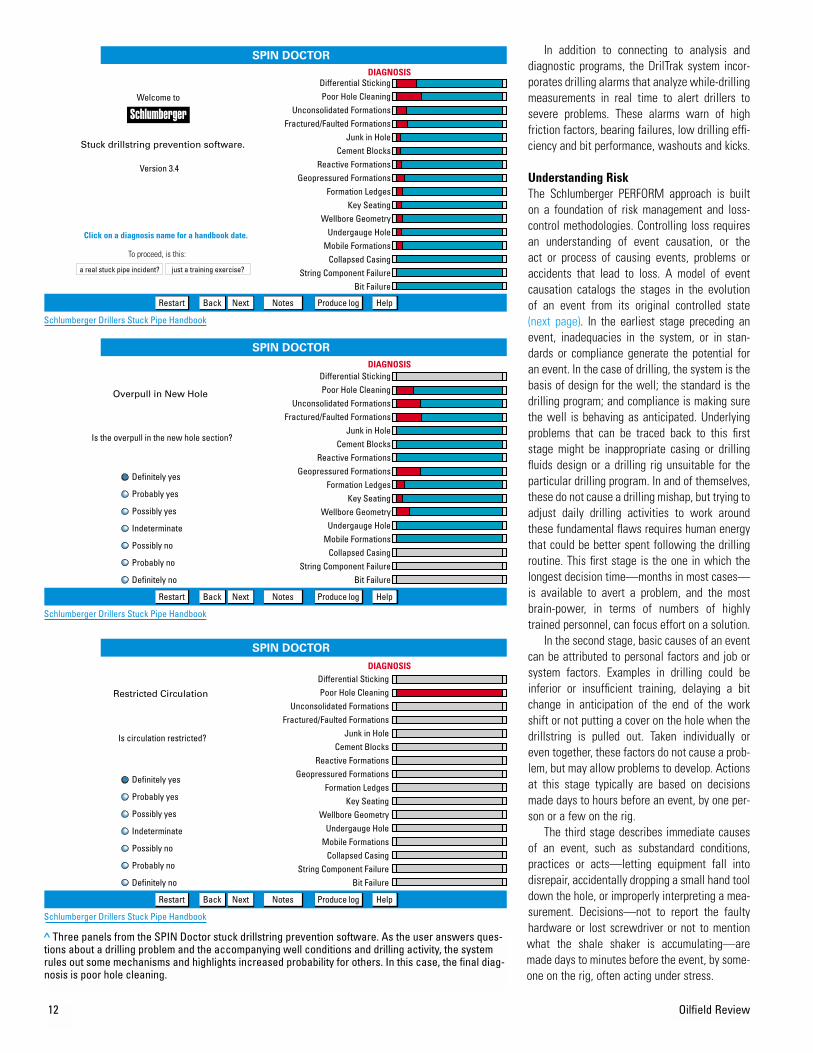
Suites of data evaluation and problem diagno-sis tools have been developed to support thesedrilling displays. Diagnostic tools, such as theSPIN Doctor stuck drillstring prevention software,zero in on the most probable cause for each prob-lem by asking the user a series of questions. TheSPIN Doctor application also contains links toelectronic documents such as the SchlumbergerStuck Pipe Handbook for more in-depth investi-gation into unforeseen problems, and can becustom-hyperlinked to any desired electronicresource, including proprietary drilling processmanuals and help files (next page).
N
500
1000
1500
2000
2500
3000
3500
4000
4500
5000
Dept
h, ft
GO
Near MissLoss
Time
DrilTrak
PP
BHA packoff at 1700 ft
Hole collapseat 3700 ft
GO
GO
lbm/gal
> Tracking drilling progress. The DrilTrak plot updates the drilling map while drilling. Changes in the trajectory are recorded along with the response of the well and the effectiveness of the drilling plan. Hazards that were avoided with no material or process loss are reported as near misses (green arrows).Losses are reported as events (red arrows).
In addition to connecting to analysis anddiagnostic programs, the DrilTrak system incor-porates drilling alarms that analyze while-drillingmeasurements in real time to alert drillers tosevere problems. These alarms warn of highfriction factors, bearing failures, low drilling effi-ciency and bit performance, washouts and kicks.
Understanding RiskThe Schlumberger PERFORM approach is built on a foundation of risk management and loss-control methodologies. Controlling loss requiresan understanding of event causation, or the act or process of causing events, problems oraccidents that lead to loss. A model of eventcausation catalogs the stages in the evolution of an event from its original controlled state(next page). In the earliest stage preceding anevent, inadequacies in the system, or in stan-dards or compliance generate the potential foran event. In the case of drilling, the system is thebasis of design for the well; the standard is thedrilling program; and compliance is making surethe well is behaving as anticipated. Underlyingproblems that can be traced back to this firststage might be inappropriate casing or drillingfluids design or a drilling rig unsuitable for theparticular drilling program. In and of themselves,these do not cause a drilling mishap, but trying toadjust daily drilling activities to work aroundthese fundamental flaws requires human energythat could be better spent following the drillingroutine. This first stage is the one in which thelongest decision time—months in most cases—is available to avert a problem, and the mostbrain-power, in terms of numbers of highlytrained personnel, can focus effort on a solution.
In the second stage, basic causes of an eventcan be attributed to personal factors and job orsystem factors. Examples in drilling could beinferior or insufficient training, delaying a bitchange in anticipation of the end of the workshift or not putting a cover on the hole when thedrillstring is pulled out. Taken individually oreven together, these factors do not cause a prob-lem, but may allow problems to develop. Actionsat this stage typically are based on decisionsmade days to hours before an event, by one per-son or a few on the rig.
The third stage describes immediate causesof an event, such as substandard conditions,practices or acts—letting equipment fall intodisrepair, accidentally dropping a small hand tooldown the hole, or improperly interpreting a mea-surement. Decisions—not to report the faultyhardware or lost screwdriver or not to mentionwhat the shale shaker is accumulating—aremade days to minutes before the event, by some-one on the rig, often acting under stress.
12 Oilfield Review
Definitely no
Definitely yes
Probably yes
Possibly yes
Indeterminate
Possibly no
Probably no
SPIN DOCTOR
Restart Back Next Notes Produce log Help
Restart Back Next Notes Produce log Help
Differential StickingPoor Hole Cleaning
Unconsolidated FormationsFractured/Faulted Formations
Junk in HoleCement Blocks
Reactive FormationsGeopressured Formations
Formation LedgesKey Seating
Wellbore GeometryUndergauge Hole
Mobile FormationsCollapsed Casing
String Component FailureBit Failure
Differential StickingPoor Hole Cleaning
Unconsolidated FormationsFractured/Faulted Formations
Junk in HoleCement Blocks
Reactive FormationsGeopressured Formations
Formation LedgesKey Seating
Wellbore GeometryUndergauge Hole
Mobile FormationsCollapsed Casing
String Component FailureBit Failure
Differential StickingPoor Hole Cleaning
Unconsolidated FormationsFractured/Faulted Formations
Junk in HoleCement Blocks
Reactive FormationsGeopressured Formations
Formation LedgesKey Seating
Wellbore GeometryUndergauge Hole
Mobile FormationsCollapsed Casing
String Component FailureBit Failure
DIAGNOSIS
DIAGNOSIS
DIAGNOSIS
Welcome to
Stuck drillstring prevention software.
Version 3.4
Click on a diagnosis name for a handbook date.
To proceed, is this:
a real stuck pipe incident? just a training exercise?
Overpull in New Hole
Is the overpull in the new hole section?
Is circulation restricted?
Restricted Circulation
Schlumberger Drillers Stuck Pipe Handbook
SPIN DOCTOR
Restart Back Next Notes Produce log Help
SPIN DOCTOR
Definitely yes
Probably yes
Possibly yes
Indeterminate
Possibly no
Probably no
Definitely no
Schlumberger Drillers Stuck Pipe Handbook
Schlumberger Drillers Stuck Pipe Handbook
> Three panels from the SPIN Doctor stuck drillstring prevention software. As the user answers ques-tions about a drilling problem and the accompanying well conditions and drilling activity, the systemrules out some mechanisms and highlights increased probability for others. In this case, the final diag-nosis is poor hole cleaning.

Summer 1999 13
In the fourth stage, the event, or incident,occurs. Drillpipe gets stuck or the well takes akick. There may be only minutes to make the rightdecision. The person making the decision thatmight free the pipe or prevent disaster is actingunder tremendous stress, and so with reducedability. Experts in the management of crises, suchas wars and natural disasters, report that undercomparable levels of stress, decision-makers uti-lize only one-fourth of the information available.
The final stage, the actual loss, results inunintended loss or damage to property and thedrilling process. The bottomhole assembly (BHA)and a section of drillpipe are lost in the hole, or akick advances to a situation that can be con-trolled only by killing the well. Afterwards, theincident is finally reported.
These risk management and cause analysisconcepts have their origins in health, safety andenvironment (HSE) awareness initiatives. Mostcompanies in the E&P industry have comprehen-sive, effective HSE awareness and training pro-grams. Maintaining an active training program isrecognized as being as important as any otheraspect of doing business. HSE training programsare based on the understanding that most inci-dents that lead to loss are caused by human error,error that could be prevented with proper care.
In the E&P industry, operators have examinedoccurrences of drilling problems and report thatmost unscheduled events can be attributed tohuman error. In one published report, 65% ofstuck-pipe incidents could be directly related toinadequate planning; 68% of incidents occurredwithin two hours of a tour change.5
Most of the techniques used in HSE trainingcourses are designed to combat human nature—to slow down speedy driving, do away with lazywaste-disposal habits or avoid distraction duringmachine operation. Managers understand theneed for constant vigilance and annual retrain-ing, and employees are required to keep theirtraining records up to date. Near-miss reportinghelps employees become more aware of situa-tions and conditions that could lead to accidents.
The same elements make an effectiveapproach to dealing with drilling incidents, andseveral of these have been incorporated into thisnew strategy for drilling. Better communication inthe form of near-miss reporting, documentation ofprocess compliance, increased awareness of teamgoals and understanding of the technical reason-ing behind contingency actions is the most impor-tant factor in applying these risk management andcause analysis methods to drilling operations.
Near-miss reporting is considered standardHSE practice for successfully reducing the fre-quency of workplace errors and accidents, butbefore the introduction of the SchlumbergerPERFORM methodology, it had not been appliedto drilling. In the past, when a well was com-pleted on schedule without major problems,everyone involved congratulated each other on ajob well done, but little thought was given toanalyzing the process that produced the success-ful result. The well may have been drilled withoutmajor problems, but it almost certainly was notdrilled without any problems at all. That itappeared to be so was because each of the smalldifficulties encountered along the way had beendealt with successfully. The story behind each ofthe forgotten small problems and its solution isthe secret of the well’s success.
Identifying drilling predicaments and report-ing them as soon as possible increases the likeli-hood that a small problem will be recognized andsolved at an early causation stage, before itbecomes unmanageable. Documenting the stepstaken to solve the problem produces two addi-tional benefits: the first is a report of the drillinghistory, complete with a record of how personnelresponded to problems. This record shows howsuccessfully workers comply with procedures.The second is an archive of problems and solu-tions that can be tapped in the future, whether indeeper sections of the same hole, or in otherwells or other fields.
Making known to all rig personnel the techni-cal reasons behind contingency actions isanother area in which good communication playsan important role. As in most situations influ-enced by habit, the easiest thing for a driller todo is what’s been done before. But if, when thetime comes, it’s important to do something dif-ferent, the driller is much more likely to react cor-rectly if the reason is understood. The case studyin the next section demonstrates how communi-cation, risk analysis, proper measurements and ateam approach help drill wells where successpreviously had been elusive.
Controlling InstabilityExperts estimate that wellbore instability coststhe industry more than $1 billion per year. Theindustry average cost of nonproductive time—often due to wellbore instability—works out toabout $1.5 million per well, and in extreme casescan reach $16 million for a single well.
Wellbore instability occurs when earthforces or interactions between the formationand the drilling fluid act to squeeze, stretch,constrict or otherwise deform the borehole.Consequences of wellbore instability are stuckpipe and BHAs, excessive trip and reaming time,mud losses, fishing or loss of equipment, side-tracks, inability to land casing, and poor loggingand cementing conditions.
Drilling plans include stability studies basedon information from neighboring wells so thatoptimal drilling trajectories, mud programs anddrilling practices can be established in advance.However, the earth doesn’t always behave aspredicted and sometimes the forces act contraryto expectations.
Wellbore instability often can be managed ifit can be detected in time. Control mechanismsinclude changing mud chemistry, mud weight andflow rate to exert more or less pressure on theformation or changing rate of penetration (ROP)or drillstring revolutions per minute (rpm) to facil-itate hole cleaning.
In an effort to develop a capability for real-time detection and control of wellborestability—while the well is being drilled—apartnership was formed in 1996 between Amoco,The Netherlands Institute of Applied Geoscience,GeoQuest and Schlumberger Cambridge Research,England. Partial funding was supplied by theEuropean Union THERMIE program.
5. Watson B and Smith R: “Training Reduces Stuck PipeCosts and Incidents,” Oil & Gas Journal, 92, no. 38(September 19, 1994): 44-47.
Causation Model
Thresholdlimit
Control
Inadequate
Basiccauses
Personalfactors
Job or systemfactors
Immediatecauses
Substandardacts or
practices
Substandardconditions
Incident
Event
Loss
Unintendedharm ordamage
•System•Standard•Compliance
>Evolution of an event. Inadequacies in the basic system, personal factors andsubstandard practice all contribute in more or less identifiable ways to a drillingproblem. Most events are not even reported until past the critical state of loss.

The methodology was tested in the Valhallfield, a major chalk reservoir discovered in 1975and operated currently by BP Amoco Norge, withpartners Elf, Amerada Hess and Enterprise. Thefield contains 600 million bbl [95 million m3] oilreserves, with a centralized production complexin 70 m [230 ft] of water. Reservoir depth is 2500 m [8200 ft]. Overall development objectivesare to increase the value of Valhall assets to 1 billion barrels [160 million m3], partly throughextended-reach drilling into downflank reserves.
Earlier drilling problems on Valhall werenumerous and typically included packoffs andstuck pipe, tools lost in hole, mud losses, side-tracking and inability to land casing or drill out ofcasing. As a consequence, there is a high riskthat wells will be suspended or abandonedbefore reaching the target.
The field test of the methodology, which wasdeveloped at Schlumberger Cambridge Research,called for an integrated approach to wellboreinstability control. The design stage compriseddata gathering, mechanical earth modelconstruction, well stability strategizing and for-mulation of a drilling plan. Execution includeddrilling monitoring, data acquisition and instabil-ity detection. Evaluation consisted of interpreta-tion of observations, updating the model andrecommending future actions.
In the planning phase for Well 2/8-A3C, amechanical earth model was generated thatdescribed the state of stress, rock properties andfailure mechanisms active in this region of theValhall structure. A mud-weight window was cal-culated taking into account traditional wellboreinstabilities, and other problems such as fracturezones—existing natural fractures—were identi-fied. A problem interval at 4000 m [13,100 ft]measured depth in the 121⁄4-in. hole section wasflagged as a zone where fracture zones couldbecome destabilized (above left).6
Depending on depth, the calculated mud-weight window is either extremely narrow ornonexistent (left). Instability was inevitable. Attoo high an effective mud weight, the fracturezone would be driven beyond its precariousbalance and cause irreparable borehole collapse.But for any mud weight below the fracturepressure, breakouts would occur. The solution,therefore, was based on recognition of theinevitability of formation failure. The only way to drill the well was to let the instability occur,then manage it. Breakout problems would becontrolled by good hole cleaning. Fracture zones, however, are uncontrollable, and must bekept stable.
14 Oilfield Review
> Valhall location (right) and mud-weight window (left).The pore pressure and minimum horizontal stress curvesare taken from the mechanical earth model. The breakoutcurve (red) is calculated as the mud weight needed toensure that none of the rock around the hole will bestressed beyond failure. Mud weight needs to lie betweenthe breakout curve and the horizontal stress curve (blue).In some sections of the hole, this is not possible.
> Problem section predicted in Valhall trajectory. Borehole inclination, earth stressesand formation characteristics combine to make this inclined section of the boreholeprone to cavings that could lead to stuck pipe if not properly managed.
0
-1000
-2000
-30004000
2000
04000 3000 2000 1000 0 -1000 -2000
W
N
Problem section
0
1000
2000
3000
4000
5000
6000
70006 8 10 12 14 16 18
Mud weight, lbm/gal
Mea
sure
d de
pth,
m
HorizontalstressPore pressure
Breakouts
10
Eldfisk
Valhall
Hod
Norwegian sector
Danish sector
UK sector
NORWAY
DENMARK
Stavanger
Bergen
km0
miles0
200
124
miles
0 km
0 6.2

Summer 1999 15
Typically, drilling in the Valhall Tertiary stratastarted with a mud weight of 14.3 lbm/gal [1.71 g/cm3]. As drilling proceeded and cavings,caused by shear failure of the wellbore wall,were observed, the mud weight would beincreased steadily, often exceeding 16 lbm/gal[1.92 g/cm3]. This caused problems in the lowersection, as it produced wellbore pressures abovethe fracture gradient. Mud was lost, and largeamounts of blocky cavings were produced fromthe naturally fractured zones, resulting in pack-offs. The new strategy proposed that drillingshould begin with mud at 14.2 lbm/gal [1.7 g/cm3], barely lower than usual, but that thisvalue should not be increased unless absolutelynecessary in response to gas, positive flowchecks or other signs of overpressure. If cavingswere produced by shear failure, they would beremoved by good hole-cleaning practices ratherthan be suppressed by higher mud weight.
The equivalent circulating density (ECD)would be kept lower than the minimum hori-zontal stress—15.3 lbm/gal [1.83 g/cm3] in theproblem zones, except in extreme circumstances.ECD is the effective mud weight that generatesthe downhole pressure observed while pumping,and is generally greater than the mud weightmeasured at surface because of frictional pres-sure drop in the annulus and cuttings loading inthe mud. In earlier Valhall wells, ECD wasallowed to exceed 15.3 lbm/gal, with consequentloss of mud to the fractures in the formation—an expensive problem, but not one previouslyregarded as threatening to wellbore integrity.
This new drilling strategy made the explicitassumption that cavings produced by shear fail-ure stemming from low mud weight would occurin quantities controllable by hole cleaning, butthat cavings produced by mud invasion and stim-ulation of fracture zones would be uncontrol-lable. It was clearly important to know whethermud invasion was occurring, and so a further partof the strategy was to monitor mud volume forlosses, and also monitor cavings at surface toidentify their source. This would be done by clas-sifying their shapes; shear-induced cavings frombreakouts are angular, those from fracture zonesare tabular and parallel-sided (above right).
If, in spite of the low mud weight, blockycavings were seen at surface, it would mean that the fracture zones were being invaded. Thiswould require addition of lost-circulation mate-rial to the mud in order to seal the fractures.
A Schlumberger PERFORM engineer wasstationed on the rig to monitor surface and down-hole measurements and advise on stuck-pipeissues: in particular to monitor and analyze cav-ings and act as liaison between the drilling staffon the rig and the wellbore-stability team onshore.
Three aspects of cavings information weretallied. First, the rate of cavings production at theshale shakers—the coarse solids separators on any rig—was recorded every 30 minutes bymeasuring the time required to fill a bucket. Thismethod may seem crude, but is reliable andversatile in terms of the number of different rigsto which it can be applied. More sophisticatedsolids-measuring devices have been tried, butfew have been satisfactory.
Second, the dominant shape of the cavingswas noted. Initially, the intention was to classifycavings into three types: angular ones originatingfrom breakouts, blocky from naturally fracturedzones, and elongate or splintery cavings fromzones of elevated pore pressure. Unfortunately,most cavings were just nondescript pieces ofbroken rock. However, some did indicate theywere from breakouts, and some from overpres-sured zones. Only two cavings were seen duringthe entire drilling program that came unam-biguously from fracture zones, attesting to thecorrectness of the selected drilling strategy.
Third, the geological age of the cavings givesan idea of where they are coming from in theinterval. This required micropaleontologicalanalysis that was not available immediately.When the results did arrive, they indicated thatall cavings were coming from the upper openholesection that had been exposed to drilling fluidsthe longest.
Onshore at the BP Amoco drilling team office,real-time data were displayed. The real-timedrilling parameters display proved popular, andgave the onshore drilling and wellbore-stabilitystaff close contact with drilling operations. Thewellbore-stability team attended morning drillingmeetings, advised on stability issues and gave aclass on wellbore stability to this group and onefrom another platform in the Valhall. The classesfocused the attention of the crew on the avoid-ance of instability problems, rather than thetraditional reactive approach, and allowed thestaff to meet and question the scientists and engineers who would be influencing theirdrilling procedures.
One of the tasks was to carefully monitor therate of penetration and the ECD. If the lattercrept up to 15.3 lbm/gal, there would be the riskof mud invading fracture zones and causing per-manent formation damage. If the ECD got toolow, cuttings and cavings could be accumulatingaround the bottomhole assembly, eventually pre-venting fluid flow and sticking the drillstring inthe hole. Rate of penetration is important in con-trolling ECD. If too much rock is drilled tooquickly, the suspended cuttings increase the muddensity and hence the ECD. While it is clear thismight lead to problems, one of the traditionalaims of the drilling crew on a rig is to drill as fastas possible. Crews assume that high ROP willhelp reach target depth more quickly, and some-times pay bonuses are tied to beating drillingschedules. In most areas, however, including theNorth Sea, a longer term view must be taken;high instantaneous drilling rates can lead toproblems that cost more to solve than is saved indrilling time.
Angular Caving
Tabular Caving
> Tabular caving (bottom) from natural fracturesand angular caving (top) caused by breakouts.Scale is in mm.
6. Kristiansen TG, Mandziuch K, Heavey P and Kol H:“Minimizing Drilling Risk in Extended Reach Wells atValhall Using Geomechanics, Geoscience and 3DVisualization Technology,” paper SPE/IADC 52863, pre-sented at the SPE/IADC Drilling Conference, Amsterdam,The Netherlands, March 9-11, 1999.

An example of the Schlumberger PERFORMprocess in action can be seen in the crew’s reac-tion to an anticipated problem. During drilling,gas levels and fluid volumes require continuousmonitoring to ensure that any gas is detected andthere is no risk of a kick developing. When back-ground gas levels were high in the interval from2100 to 2200 m [6890 to 7220 ft], the standardresponse would have been to increase mudweight substantially to suppress gas influx intothe borehole. This would have led to the destabi-lization of the critical fractured zone lower,between 4100 and 4300 m [13,450 to 14,100 ft].The driller was advised that mud weight had to be kept low, and that another way to controlgas leakage was to slow down. The mud-weight increase was restricted to 14.6 lbm/gal[1.75 g/cm3] and the rate of penetration wasreduced to below 30 m/hr [98 ft/hr]. The lowerROP decreased the rate at which crushed rockreleased gas into the annulus, and these actionsreduced background gas levels from the 20 to35% range down to less than 5%, while avoidingproblems deeper in the well.
The reservoir was penetrated ahead of sched-ule, with much lower mud loss to the formationthan usual and negligible activation of fracturezones. The asset team acknowledges that theimplementation of real-time wellbore-stabilitycontrol significantly reduced the risk and drillingcosts to the top of the reservoir, and achievedoptimal well construction technique earlier in thefield development cycle.
16 Oilfield Review
> Structure of the salt dome responsible for the Mungo field accumulation. White curvesare well trajectories and the yellow lines on the dome are interpreted faults.
500
1000
1500
2000
2500
30000 500 1000 1500 2000 2500 3000
27.6Tilt
z coord
30.6Sigma1
Sigma2 24.58
23.54Sigma3
x coord 1004
1407
Tilt of 27.6 degreeson horizontal stress
Outlineof diapir
Distance, m
Mea
sure
d de
pth,
m
Well trajectory
> Wellbore trajectory on a vertical slice throughthe stress field modeled around the Mungo field.In an unperturbed earth, the maximum principalstress is vertical, and the intermediate and minimum ones, horizontal. With the intrusion of salt, the stress field has been perturbed andtilted. This earth model can be interrogated atany point and the stresses visualized as axesthrough a sphere. In this example, the model hasbeen interrogated at 1500 m: the red crosshairsand circle indicate that the maximum and interme-diate principal stresses are tilted 27.6 degrees.

Summer 1999 17
Another field in the North Sea experiencedsimilar gains in drilling efficiency through opti-mized planning and monitoring of wellbore stabil-ity and hole-cleaning practices. Developmentwells in the Mungo field in the Eastern TroughArea Project (ETAP) encountered extreme instabil-ity problems as they neared the flanks of the over-hanging salt diapir (previous page, top). Tectonicactivity associated with the salt emplacementhad fractured and weakened formations throughwhich wells were to pass on their way to thereservoir. The highly disturbed sediments aroundthe salt intensified the hole-cleaning problem.Cavings, whether bounded by fractures or byweakened bedding planes, clogged the wellbore.Stuck-pipe problems were especially severe inthe long, inclined 60° sections of the S-shapedtrajectories that were necessitated by the cen-trally located platform. Overpressured formationsand high-pressure chalk rafts added further risk tothe drilling program.
The four wells in the first phase of Mungodevelopment drilling had experienced large costoverruns in the 121⁄4-in. sections. For the subse-quent phase of development, a mechanical earthmodel was constructed for the Mungo structureand used to plan the second phase of develop-ment wells. Some of these wells pierced the saltfor a 133⁄8-in. casing point then followed the saltdownflank to the reservoir sand (previous page,bottom). As in some sections of the Valhall wells,stress profiles indicated cavings would be abun-dant, so good hole-cleaning practices would becrucial to successful drilling. Downhole monitor-ing of ECD with the APWD Annular PressureWhile Drilling tool would help the engineerdetect hole-cleaning problems before they couldcause stuck pipe.7
In Well P2, the first well of the second phaseof Mungo development, wellbore instability didcause large amounts of cavings to enter theborehole (right). However, the combination ofsurface detection of cavings and cuttings, down-hole measurements for hydraulics monitoringand attentive drilling overcame this problem. TheNPT was significantly reduced, with substantialcost savings.
Currently, the Mungo wells team has aSchlumberger PERFORM engineer offshore and ageomechanical expert onshore as part of thedrilling team. This engineer and members of theonshore team, consisting of the geomechanicalexpert, drilling engineer, directional planner andgeologist, hold a morning conference call to dis-cuss what has occurred over the last 24 hours andwhat can be expected for the upcoming day. Theresults of this meeting are presented at the regu-
lar morning call where everyone is briefed andmade fully aware of any potential problems for thenext 24 hours. This process worked well on therecently drilled P3 well. A situation involving pos-sible losses was avoided by keeping the ECD lowwhile drilling through a fracture. A small volume ofmud was lost, but drilling continued unabated.
W E0
1000
1500
500
2000
2500
0 500 1000 1500 2000
Gas-oil contact, 1680 m
Oil-water contact, 2645 m
Top chalk
Top reservoir
30 in.
18 5/8 in.
13 3/8 in.
9 5/8 in.
Mea
sure
d de
pth,
m
Distance, m
Salt dome
Fracture-boundedcaving
Weak bedding-plane caving
> Cavings shapes predicted and found along the trajectory. The volume around the topof the salt dome was predicted to be highly fractured and prone to fracture-boundedcavings. Deeper along the inclined section, cavings were found to separate alongweaknesses in bedding planes.
7. For more on the application of the APWD tool in theMungo field and others: Aldred W, Cook J, Bern P,Carpenter B, Hutchinson M, Lovell J, Rezmer-Cooper Iand Leder PC: “Using Downhole Annular PressureMeasurements to Improve Drilling Performance,” OilfieldReview 10, no. 4 (Winter 1998): 40-55.

Optimizing Bits and Drilling PracticeThe Schlumberger PERFORM techniques for opti-mizing drilling performance can be applied toother drilling challenges. In addition to managingwellbore instability and promoting good hole-cleaning practice, the methodology has beenused to improve drilling efficiency by supportingbit selection and appropriate drilling practice toreduce damage to drillstring components.
Chevron is drilling and operating offshore inthe Cabinda enclave of Angola (above). Their cur-rent efforts concentrate on the South Sanhafields where the main reservoir, the Pinda forma-tion, is the deepest and hardest to drill. Theinterbedding of hard and soft layers in the Pindaformation plays havoc with drilling equipment,and it is a challenge to prolong the lives of bitsand other BHA components. In one instance,after drilling just two wells, Sedco Forex had toscrap about 80 joints of heavy-weight and stan-dard drillpipe due to eccentric wear.
The main goals for the Schlumberger PERFORMengineer were to improve ROP and eliminate drill-string failures. In essence, this meant finding waysto ensure that all the rig energy imparted throughthe rotary table or topdrive to the drillstring and bitbe used constructively to cut rock rather than todestroy the bit and drillstring. The differencebetween the two situations sometimes can besmall, and the best way to avoid the latter is bycareful planning, understanding the process andmonitoring both surface and downhole measure-ments in real time.
Standard practice for increasing ROP was toincrease weight on bit (WOB). But increasingWOB can cause other problems, includingincreased stick-slip and torsional vibration,which in turn damage the drillstring and
ultimately lead to higher per-foot costs. Stick-slipoccurs when high friction between the bit andthe formation actually stops the bit from rotat-ing—the stick phase—even though the drillpipeis still being turned at a constant rate on surface.After a short delay, slip takes over when torquebuilt up in the twisted drillpipe overcomes thefriction and the bit turns, but several times fasterthan the speed transferred from the rotary tableor topdrive. Torsional vibration, or oscillation ofthe drillstring around its rotational axis, is one ofthe three modes of drillstring vibration, the othertwo being axial—along the long axis of pipe, andlateral—from side to side across the pipe.8
Introduction of the Schlumberger PERFORMtechnique produced immediate results. In the firstwell to use such an engineer, monitoring surface
and downhole measurements of weight on bittorque, shocks and vibrations provided a clearguide to controlling stick-slip, shocks and vibra-tions by modifying WOB (below). Surface (SWOB)and downhole weight on bit (DWOB) were seen tocorrelate closely with the occurrence of torsionalvibrations at XX325 ft brought on by stick-slip, so astick-slip threshold weight was determined, underwhich the WOB would allow smooth drilling. Forthresholding purposes, the downhole weight on bitmeasurement was more reliable than that mea-sured on surface. For example, at XX360 ft, wheretorsional vibrations are low, the DWOB lies belowthe threshold, but the SWOB is above it. This is incontrast to the next lower section in which DWOB(and SWOB) are above the threshold, and vibra-tions are set in motion.
18 Oilfield Review
XX320
XX340
XX360
XX380
Dept
h, ft
0 50 0
0 40
40
ROP
SWOB
DWOBft/hr klbf
klbfSTOR
DTOR10
20
klbf
klbf 0 10
100 300Downhole
Axial Vibration
Lateral Vibration0 40
0 3000rpm
0 200
0 3000SHK Width
SHK Peak
Torsional Vib0
0 G
G µsec
G
radian/sec
Stick-slipthreshold
weight
> Surface and downhole measurements for optimizing drilling in a Chevron Cabinda well.Increases in surface (SWOB) and downhole (DWOB) weight on bit (track 2) correlate with theonset of dangerous torsional vibrations (track 5) induced by stick-slip, first seen in the zone fromXX325 to XX330 ft. To avoid torsional vibrations, a stick-slip threshold weight was determined andtied to measured DWOB, which is more reliable than SWOB. This can be seen in the interval fromXX360 to XX369 ft: there are no torsional vibrations when DWOB is below the threshold, butSWOB is above the threshold and would have given a false alarm.
NIGERIA
CAMEROON
CONGOGABON
ZAIRE
ANGOLA
GHANA
Cabinda
> Cabinda, a northern enclave of Angola on the west coast of Africa, having crude oil asits dominant export.

Summer 1999 19
The well took 11 days and one bit run to drillthe 10,000 ft [3050 m] to the top of the Pinda, then23 days with 6 bit runs to drill through the 3000-ft[900-m] Pinda. The sporadic success of any par-ticular bit and BHA combination in this field wasunexplainable. Sometimes one combinationwould achieve excellent ROP and footage, and atother times it would fail after the initial few feet.
The engineer combined data from surface anddownhole measurements and rock strength anal-ysis and related these to previous bit and BHAperformance. This allowed estimation of optimalranges for the while-drilling measurements andhelped in subsequent bit and BHA selection.Then specific drilling performance measurementswere monitored in real time on the rig and keptwithin the optimized range so as to achieve opti-mal cost per foot.
The experience gained while drilling this wellwas applied to subsequent wells. In all laterwells, the number of shocks measured with athreshold shock sensor that detects shocksgreater than 100 G decreased from a range of 6 to 8 million in the Pinda formation to almostzero. The problems of eccentric drillpipe weardisappeared completely and the learning curvefor selecting the right bit and BHA sped up,resulting in improved drilling performance.
Tools for SuccessThe successes delivered by the SchlumbergerPERFORM process stem from the combination ofSchlumberger technical strengths in measure-ment and interpretation with the operator’sdrilling expertise. High-quality while-drilling dataand accompanying analyses are vital for success-ful drilling, but they are most valuable when usedin a consistent way to support decisions madeduring the drilling process.
This process is a series of decisions and asso-ciated actions taken during the planning andexecution of a project that result in a completedwell. The degree of success or failure and effi-ciency of the well is determined by the quality ofthose decisions. Effective decision-makingdepends on having an accurate view of current
well conditions, understanding the consequencesof a decision and being prepared for the futurewith contingency plans. The SchlumbergerPERFORM initiative impacts this process most sig-nificantly by helping to provide an accurate view ofthe current conditions and a look ahead at poten-tial hazards. The result is that better decisions canbe made by transferring the decision-makingperiod from the stressful moments surrounding anincident to some earlier time when judgment isnot impaired by anxiety and pressure.
Researchers are investigating ways toimprove the decision-making process by makingmore data available faster and using knowledgegained in other areas. For example, new tech-niques are being devised for estimating the riskof a drilling incident such as stuck pipe. Usingstandpipe pressure and torque data from the
Valhall wellbore stability case study discussedearlier, scientists at Schlumberger CambridgeResearch have produced a stuck-pipe risk profilethat begins to foretell hole-cleaning problems(above). With further testing and experience,these advances will eventually change alarmsfrom signaling a surprising event when it occursto advising drilling teams long before the prob-lem becomes dangerous.
The oil industry, like all others, strives forcost-effectiveness and productivity. Eliminationof waste and losses, whether in process or mate-rials, is a key goal for all successful companies,regardless of prevailing economic conditions.Increasing drilling efficiency by managing drillingrisk is a sure way for E&P companies to achievethat objective. —LS
Risk
0
0.5
1
X450 X475 X500 X525 X550 X575 X600 X625 X650
Depth, m
Sta
ndpi
pe p
ress
ure,
psi
3100
3200
3300
3400
3500
Torq
ue, k
lbf
10
15
20Valhall Stuck-Pipe Risk
> Predicting the possibility of stuck pipe in the Valhall field. Torque (top) and standpipe pressure(middle) measured while drilling are two elements, along with signal processing techniques,that help identify well sections where the risk of stuck pipe is high (bottom). The shaded barsindicate where the drilling team did experience drilling difficulties, mostly related to hole-cleaning issues.
8. Jardine S, Malone D and Sheppard M: “Putting aDamper on Drilling’s Bad Vibrations,” Oilfield Review 6,no. 1 (January 1994): 15-20.