management interface and security - cisco€¦ · configuring the management interface and security...
TRANSCRIPT
Cisco SCE 200OL-29136-01
C H A P T E R 5
Configuring the Management Interface and SecurityRevised: June 21, 2013, OL-29136-01
IntroductionThis module describes how to configure the physical management interfaces (ports) as well as the various management interface applications, such as SNMP, SSH, and TACACS+. It also explains how to configure users, passwords, IP configuration, clock and time zone, and domain name settings.
• About Management Interface and Security, page 5-2
• Configuring the Management Ports, page 5-3
• Entering the Management Interface Configuration Mode, page 5-4
• Configuring the Management Port Physical Parameters, page 5-5
• Configuring Management Interface Redundancy, page 5-9
• Configuring Management Interface Security, page 5-11
• Configuring the Available Interfaces, page 5-13
• Configuring and Managing the SNMP Interface, page 5-35
• Managing Passwords, page 5-48
• IP Configuration, page 5-54
• Configuring Time Clocks and Time Zone, page 5-59
• Configuring SNTP, page 5-66
• Configuring Domain Name Server (DNS) Settings, page 5-69
• Configuring the Management Port Physical Parameters, page 5-73
5-10 and Cisco SCE 1000 Software Configuration Guide
Chapter 5 Configuring the Management Interface and SecurityAbout Management Interface and Security
About Management Interface and Security The SCE platform is equipped with two RJ-45 management (MNG) ports. These ports provide access from a remote management console to the SCE platform via a LAN.
The two management ports support management interface redundancy, providing the possibility for a backup management link.
In addition to the Layer 1 security of a backup management link, the Service Control platform provides a further management interface security feature; an IP filter that monitors for various types of TCP/IP attacks. This filter can be configured with thresholds rates both for defining an attack and defining the end of an attack.
Note The second management port is reflected in all objects related to it in the SNMP interface.
Perform the following tasks to configure the management interface and management interface security:
• Configure the management port:
– Physical parameters
– Specify active port (if not redundant installation)
– Redundancy (if redundant installation)
• Configure management interface security
– Enable IP fragment filtering
– Configure the permitted and not-permitted IP address monitor
5-2Cisco SCE 2000 and Cisco SCE 1000 Software Configuration Guide
OL-29136-01
Chapter 5 Configuring the Management Interface and SecurityConfiguring the Management Ports
Configuring the Management Ports Perform the following tasks to configure the management ports:
• Configure the IP address and subnet mask (only one IP address for the management interface, not one IP address per port).
• Configure physical parameters:
– Duplex
– Speed
• Configure redundant management interface behavior (optional):
– Fail-over mode
• If fail-over mode is disabled, specify the active port (optional).
To configure the system with management interface redundancy, see Configuring Management Interface Redundancy, page 5-9 Configuring the Management Ports for Redundancy.
Step 1 Cable the desired management port, connecting it to the remote management console via the LAN.
Step 2 Disable the automatic fail-over mode. (See How to Disable the Automatic Fail-Over Mode, page 5-10.)
Step 3 Configure the management port physical parameters. (See Configuring the Management Port Physical Parameters, page 5-5.)
5-3Cisco SCE 2000 and Cisco SCE 1000 Software Configuration Guide
OL-29136-01
Chapter 5 Configuring the Management Interface and SecurityEntering the Management Interface Configuration Mode
Entering the Management Interface Configuration Mode When entering Management Interface Configuration Mode, you must indicate the number of the management port to be configured:
• 0/1 — Mng port 1
• 0/2 — Mng port 2
The following Management Interface commands are applied only to the port specified when entering Management Interface Configuration Mode. Therefore, each port must be configured separately:
• speed
• duplex
The following Management Interface commands are applied to both management ports, regardless of which port had been specified when entering Management Interface Configuration Mode. Therefore, both ports are configured with one command:
• ip address
• auto-fail-over
Step 1 Type configure and press Enter.
Enables Global Configuration mode.
The command prompt changes to SCE(config)#.
Step 2 Type interface Mng {0/1|0/2} and press Enter.
Enables Management Interface Configuration mode.
The command prompt changes to SCE(config if)#
5-4Cisco SCE 2000 and Cisco SCE 1000 Software Configuration Guide
OL-29136-01
Chapter 5 Configuring the Management Interface and SecurityConfiguring the Management Port Physical Parameters
Configuring the Management Port Physical Parameters This interface has a transmission rate of 10 or 100 Mbps and is used for management operations and for transmitting RDRs, which are the output of traffic analysis and management operations.
• Setting the IP Address and Subnet Mask of the Management Interface, page 5-5
• Configuring the Management Interface Speed and Duplex Parameters, page 5-6
• Specifying the Active Management Port, page 5-7
Setting the IP Address and Subnet Mask of the Management Interface • Options, page 5-5
• Setting the IP Address and Subnet Mask of the Management Interface: Example, page 5-6
The user must define the IP address of the management interface.
When both management ports are connected, providing a redundant management port, this IP address always acts as a virtual IP address for the currently active management port, regardless of which port is the active port.
Options
The following options are available:
• IP address — The IP address of the management interface.
If both management ports are connected, so that a backup management link is available, this IP address will be act as a virtual IP address for the currently active management port, regardless of which physical port is currently active.
• subnet mask — subnet mask of the management interface.
Step 1 From the SCE(config if)# prompt, type ip address ip-address subnet-mask and press Enter.
The command might fail if there is a routing table entry that is not part of the new subnet defined by the new IP address and subnet mask.
Note Changing the IP address of the management interface via telnet will result in loss of the telnet connection and inability to reconnect with the interface.
Note After changing the IP address, you must reload the SCE platform so that the change will take effect properly in all internal and external components of the SCE platform. (See Rebooting and Shutting Down the SCE Platform, page 3-17.)
5-5Cisco SCE 2000 and Cisco SCE 1000 Software Configuration Guide
OL-29136-01
Chapter 5 Configuring the Management Interface and SecurityConfiguring the Management Port Physical Parameters
Setting the IP Address and Subnet Mask of the Management Interface: Example
The following example shows how to set the IP address of the SCE platform to 10.1.1.1 and the subnet mask to 255.255.0.0.
SCE(config if)#ip address 10.1.1.1 255.255.0.0
Configuring the Management Interface Speed and Duplex Parameters This section presents sample procedures that describe how to configure the speed and the duplex of the Management Interface.
Both these parameters must be configured separately for each port.
• Interface State Relationship to Speed and Duplex, page 5-6
• How to Configure the Speed of the Management Interface, page 5-6
• How to Configure the Duplex Operation of the Management Interface, page 5-7
Interface State Relationship to Speed and Duplex
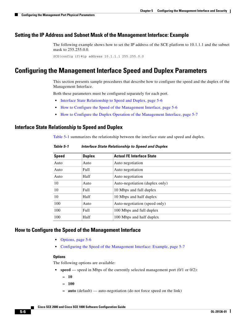
Table 5-1 summarizes the relationship between the interface state and speed and duplex.
How to Configure the Speed of the Management Interface
• Options, page 5-6
• Configuring the Speed of the Management Interface: Example, page 5-7
Options
The following options are available:
• speed — speed in Mbps of the currently selected management port (0/1 or 0/2):
– 10
– 100
– auto (default) — auto-negotiation (do not force speed on the link)
Table 5-1 Interface State Relationship to Speed and Duplex
Speed Duplex Actual FE Interface State
Auto Auto Auto negotiation
Auto Full Auto negotiation
Auto Half Auto negotiation
10 Auto Auto-negotiation (duplex only)
10 Full 10 Mbps and full duplex
10 Half 10 Mbps and half duplex
100 Auto Auto-negotiation (speed only)
100 Full 100 Mbps and full duplex
100 Half 100 Mbps and half duplex
5-6Cisco SCE 2000 and Cisco SCE 1000 Software Configuration Guide
OL-29136-01
Chapter 5 Configuring the Management Interface and SecurityConfiguring the Management Port Physical Parameters
If the duplex parameter is configured to auto, changing the speed parameter has no effect (see ).
Step 1 From the SCE(config if)# prompt, type speed 10|100|auto and press Enter.
Specify the desired speed option.
Configuring the Speed of the Management Interface: Example
The following example shows how to use this command to configure the Management port to 100 Mbps speed.
SCE(config if)#speed 100
How to Configure the Duplex Operation of the Management Interface
• Options, page 5-7
• Configuring the Duplex Operation of the Management Interface: Example, page 5-7
Options
The following options are available:
• duplex — duplex operation of the currently selected management port (0/1 or 0/2):
– full
– half
– auto (default) — auto-negotiation (do not force duplex on the link)
If the speed parameter is configured to auto, changing the duplex parameter has no effect (see ).
Step 1 From the SCE(config if)# prompt, type duplex auto|full|half and press Enter.
Specify the desired duplex option.
Configuring the Duplex Operation of the Management Interface: Example
The following example shows how to use this command to configure a management port to half duplex mode.
SCE(config if)#duplex half
Specifying the Active Management Port • Options, page 5-8
• Specifying the Active Management Port: Example, page 5-8
5-7Cisco SCE 2000 and Cisco SCE 1000 Software Configuration Guide
OL-29136-01
Chapter 5 Configuring the Management Interface and SecurityConfiguring the Management Port Physical Parameters
This command explicitly specifies which management port is currently active. Its use varies slightly, depending on whether the management interface is configured as a redundant interface (auto fail-over enabled) or not (auto fail-over disabled).
• auto fail-over enabled (automatic mode) — the specified port becomes the currently active port, in effect forcing a fail-over action even if a failure has not occurred.
• auto fail-over disabled (manual mode) — the specified port should correspond to the cabled Mng port, which is the only functional port and therefore must be and remain the active management port.
Note This command is a Privileged Exec command, unlike the other commands in this section, which are Mng Interface Configuration commands. If in Mng interface configuration mode, you must exit to the privileged exec mode and see the SCE# prompt displayed.
Options
The following options are available:
• slot-number/interface-number — The interface number (0/1 or 0/2) of the management port that is specified as the active port.
Step 1 From the SCE# prompt, type Interface Mng {0/1 | 0/2} active-port and press Enter.
Specify the desired MNG interface.
Specifying the Active Management Port: Example
The following example shows how to use this command to configure Mng port 2 as the currently active management port.
SCE# Interface Mng 0/2 active-port
5-8Cisco SCE 2000 and Cisco SCE 1000 Software Configuration Guide
OL-29136-01

Chapter 5 Configuring the Management Interface and SecurityConfiguring Management Interface Redundancy
Configuring Management Interface Redundancy • About Management Port Redundancy, page 5-9
• How to Configure the Management Ports for Redundancy, page 5-9
• Configuring the Fail-Over Mode, page 5-10
About Management Port Redundancy The SCE platform contains two RJ-45 management ports. The two management ports provide the possibility for a redundant management interface, thus ensuring management access to the SCE platform even if there is a failure in one of the management links. If a failure is detected in the active management link, the standby port automatically becomes the new active management port.
Note that both ports must be connected to the management console via a switch. In this way, the IP address of the MNG port is always the same, regardless of which physical port is currently active.
Important information:
• Only one port is active at any time.
• The same virtual IP address and MAC address are assigned to both ports.
• Default:
– Port 1 = active
– Port 2 = standby
• The standby port sends no packets to the network and packets from the network are discarded.
• When a problem in the active port is encountered, the standby port automatically becomes the new active port.
• Link problem, with switch to standby MNG port, is declared after the link is down for 300 msec.
• Service does not revert to the default active port if/when that link recovers. The currently active MNG port remains active until link failure causes a switch to the other MNG port.
How to Configure the Management Ports for Redundancy
Step 1 Cable both management ports (Mng 1 and Mng 2), connecting them both to the remote management console via the LAN and via a switch.
Using the switch ensures that the IP address of the MNG port is always the same, regardless of which physical port is currently active
Step 2 Configure the automatic fail-over mode.
See Configuring the Fail-Over Mode, page 5-10.
Step 3 Configure the IP address for the management interface.
The same IP address will always be assigned to the active management port, regardless of which physical port is currently active.
See Setting the IP Address and Subnet Mask of the Management Interface, page 5-5.
5-9Cisco SCE 2000 and Cisco SCE 1000 Software Configuration Guide
OL-29136-01

Chapter 5 Configuring the Management Interface and SecurityConfiguring Management Interface Redundancy
Step 4 Configure the speed and duplex for both management ports.
See Configuring the Management Interface Speed and Duplex Parameters, page 5-6.
Configuring the Fail-Over ModeThis section provides details on the Cisco SCE device failover modes.
• Options, page 5-10
• How to Enable the Automatic Fail-Over Mode, page 5-10
• How to Disable the Automatic Fail-Over Mode, page 5-10
Use the following command to enable automatic fail-over. The automatic mode must be enabled to support management interface redundancy. This mode automatically switches to the backup management link when a failure is detected in the currently active management link.
This parameter can be configured when in management interface configuration mode for either management port, and is applied to both ports with one command.
Options
The following options are available:
• auto/ no auto — Enable or disable automatic fail-over switching mode
– Default — auto (automatic mode)
How to Enable the Automatic Fail-Over Mode
Step 1 From the SCE(config if)# prompt, type auto-fail-over and press Enter.
How to Disable the Automatic Fail-Over Mode
Step 1 From the SCE(config if)# prompt, type no auto-fail-over and press Enter.
5-10Cisco SCE 2000 and Cisco SCE 1000 Software Configuration Guide
OL-29136-01

Chapter 5 Configuring the Management Interface and SecurityConfiguring Management Interface Security
Configuring Management Interface SecurityManagement security is defined as the capability of the SCE platform to cope with malicious management conditions that might lead to global service failure. This section provides information on how to configure the management interface security.
• Configuring the IP Fragment Filter, page 5-11
• Configuring the Permitted and Not-Permitted IP Address Monitor, page 5-12
• Monitoring Management Interface IP Filtering, page 5-12
Resiliency to attacks on the management port includes the following features:
• The SCE platform remains stable during flooding attack.
• The number of TCP/IP stack control protocol vulnerabilities is minimized.
• The availability of reporting capabilities on attacks on the management port.
There are two parallel security mechanisms:
• Automatic security mechanism — monitors the TCP/IP stack rate at 200 msec intervals and throttles the rate from the device if necessary.
This mechanism always functions and is not user-configurable.
• User-configurable security mechanism — accomplished via two IP filters at user-configurable intervals:
– IP fragment filter — Drops all IP fragment packets
– IP filter monitor — Measures the rate of accepted and dropped packets for both permitted and not-permitted IP addresses.
Configuring the IP Fragment Filter • Options, page 5-11
• How to Enable the IP Fragment Filter, page 5-11
• How to Disable the IP Fragment Filter, page 5-12
Options
The following options are available:
• enable/disable — Enable or disable IP fragment filtering
– Default — disable
How to Enable the IP Fragment Filter
Step 1 From the SCE(config)# prompt, type ip filter fragment enable and press Enter.
5-11Cisco SCE 2000 and Cisco SCE 1000 Software Configuration Guide
OL-29136-01
Chapter 5 Configuring the Management Interface and SecurityConfiguring Management Interface Security
How to Disable the IP Fragment Filter
Step 1 From the SCE(config)# prompt, type ip filter fragment disable and press Enter.
Configuring the Permitted and Not-Permitted IP Address Monitor
Options
The following options are available:
• I p permitted/ip not-permitted — Specifies whether the configured limits apply to permitted or not-permitted IP addresses.
If neither keyword is used, it is assumed that the configured limits apply to both permitted and not-permitted IP addresses.
• low rate — lower threshold; the rate in Mbps that indicates the attack is no longer present.
– Default — 20
• high rate — upper threshold; the rate in Mbps that indicates the presence of an attack.
– Default — 20
• burst size — duration of the interval in seconds that the high and low rates must be detected in order for the threshold rate to be considered to have been reached
– Default — 10
Step 1 From the SCE(config)# prompt, type ip filter monitor {ip_permited|ip_not_permited} low_rate low_rate high_rate high_rate burst burst size and press Enter.
Monitoring Management Interface IP Filtering Use this command to display the following information for management interface IP filtering.
• IP fragment filter enabled or disabled
• configured attack threshold (permitted and not-permitted IP addresses)
• configured end of attack threshold (permitted and not-permitted IP addresses)
• burst size in seconds (permitted and not-permitted IP addresses)
Step 1 From the SCE> prompt, type show ip filter and press Enter.
5-12Cisco SCE 2000 and Cisco SCE 1000 Software Configuration Guide
OL-29136-01

Chapter 5 Configuring the Management Interface and SecurityConfiguring the Available Interfaces
Configuring the Available Interfaces The system allows you to configure the Telnet and SNMP interfaces according to the manner in which you are planning to manage the SCE platform and the external components of the system.
• Configuring TACACS+ Authentication, Authorization, and Accounting, page 5-13
• Configuring Access Control Lists (ACLs), page 5-27
• Configuring the Telnet Interface, page 5-29
• Configuring the SSH Server, page 5-30
• Enabling the SNMP Interface, page 5-33
Configuring TACACS+ Authentication, Authorization, and Accounting • Information About TACACS+ Authentication, Authorization, and Accounting, page 5-13
• Configuring the SCE Platform TACACS+ Client, page 5-16
• How to Manage a User Database, page 5-19
• Configuring AAA Login Authentication, page 5-23
• Configuring AAA Privilege-Level Authorization Methods, page 5-24
• Configuring AAA Accounting, page 5-25
• Monitoring the TACACS+ Servers, page 5-26
• Monitoring TACACS+ Users, page 5-26
Information About TACACS+ Authentication, Authorization, and Accounting
TACACS+ is a security application that provides centralized authentication of users attempting to gain access to a network element.
The implementation of TACACS+ protocol allows customers to configure one or more authentication servers for the SCE platform, providing a secure means of managing the SCE platform, as the authentication server will authenticate each user. This then centralizes the authentication database, making it easier for the customers to manage the SCE platform.
TACACS+ services are maintained in a database on a TACACS+ server running, typically, on a UNIX or Windows NT workstation. You must have access to and must configure a TACACS+ server before the configured TACACS+ features on your network element are available.
The TACACS+ protocol provides authentication between the network element and the TACACS+ ACS, and it can also ensure confidentiality, if a key is configured, by encrypting all protocol exchanges between a network element and a TACACS+ server.
The TACACS+ protocol provides the following three features:
• Login authentication
• Privilege level authorization
• Accounting
The following subsections are available:
• Login Authentication, page 5-14
5-13Cisco SCE 2000 and Cisco SCE 1000 Software Configuration Guide
OL-29136-01
Chapter 5 Configuring the Management Interface and SecurityConfiguring the Available Interfaces
• Accounting, page 5-14
• Privilege-Level Authorization, page 5-15
• General AAA Fallback and Recovery Mechanism, page 5-15
• About Configuring TACACS+, page 5-15
Login Authentication
The SCE platform uses the TACACS+ ASCII authentication message for CLI, Telnet and SSH access.
TACACS+ allows an arbitrary conversation to be held between the server and the user until the server receives enough information to authenticate the user. This is usually done by prompting for a username and password combination.
The login and password prompts may be provided by the TACACS+ server, or if the TACACS+ server does not provide the prompts, then the local prompts will be used.
The user log in information (user name and password) is transmitted to the TACACS+ server for authentication. If the TACACS+ server indicates that the user is not authenticated, the user will be re-prompted for the user name and password. The user is re-prompted a user-configurable number of times, after which the failed login attempt is recorded in the SCE platform user log and the telnet session is terminated (unless the user is connected to the console port.)
The SCE platform will eventually receive one of the following responses from the TACACS+ server:
• ACCEPT – The user is authenticated and service may begin.
• REJECT – The user has failed to authenticate. The user may be denied further access, or will be prompted to retry the login sequence depending on the TACACS+ server.
• ERROR – An error occurred at some time during authentication. This can be either at the server or in the network connection between the server and the SCE platform. If an ERROR response is received, the SCE platform will try to use an alternative method or server for authenticating the user.
• CONTINUE – The user is prompted for additional authentication information.
If the server is unavailable, the next authentication method is attempted, as explained in General AAA Fallback and Recovery Mechanism, page 5-15.
Accounting
The TACACS+ accounting supports the following functionality:
• Each executed command (the command must be a valid one) will be logged using the TACACS+ accounting mechanism (including login and exit commands).
• The command is logged both before and after it is successfully executed.
• Each accounting message contains the following:
– User name
– Current time
– Action performed
– Command privilege level
TACACS+ accounting is in addition to normal local accounting using the SCE platform dbg log.
5-14Cisco SCE 2000 and Cisco SCE 1000 Software Configuration Guide
OL-29136-01
Chapter 5 Configuring the Management Interface and SecurityConfiguring the Available Interfaces
Privilege-Level Authorization
After a successful login the user is granted a default privilege level of 0, giving the user the ability to execute a limited number of commands. Changing privilege level is done by executing the "enable" command. This command initiates the privilege level authorization mechanism.
Privilege level authorization in the SCE platform is accomplished by the use of an "enable" command authentication request. When a user requests an authorization for a specified privilege level, by using the "enable" command, the SCE platform sends an authentication request to the TACACS+ server specifying the requested privilege level. The SCE platform grants the requested privilege level only after the TACACS+ server does the following:
• Authenticates the " enable " command password
• Verifies that the user has sufficient privileges to enter the requested privilege level.
Once the user privilege level has been determined, the user is granted access to a specified set of commands according to the level granted.
As with login authentication, if the server is unavailable, the next authentication method is attempted, as explained in General AAA Fallback and Recovery Mechanism, page 5-15.
General AAA Fallback and Recovery Mechanism
The SCE platform uses a fall-back mechanism to maintain service availability in case of an error.
The SCE platform uses a fall-back mechanism to maintain service availability in case of an error.
The AAA methods available are:
• TACACS+ – AAA is performed by the use of a TACACS+ server, allows authentication, authorization and accounting.
• Local – AAA is performed by the use of a local database, allows authentication and authorization.
• Enable – AAA is performed by the use of user configured passwords, allows authentication and authorization.
• None – no authentication\authorization\accounting is performed.
In the current implementation the order of the methods used isn't configurable but the customer can choose which of the methods are used. The current order is
• TACACS+
• Local
• Enable
• None
Note Important: If the server goes to AAA fault, the SCE platform will not be accessible until one of the AAA methods is restored. In order to prevent this, it is advisable to use the "none" method as the last AAA method. If the SCE platform becomes un-accessible, the shell function "AAA_MethodsReset" will allow the user to delete the current AAA method settings and set the AAA method used to "Enable".
About Configuring TACACS+
The following is a summary of the procedure for configuring TACACS+. All steps are explained in detail in the remainder of this section.
1. Configure the remote TACACS+ servers.
5-15Cisco SCE 2000 and Cisco SCE 1000 Software Configuration Guide
OL-29136-01

Chapter 5 Configuring the Management Interface and SecurityConfiguring the Available Interfaces
Configure the remote servers for the protocols. Keep in mind the following guidelines
– Configure the encryption key that the server and client will use.
– The maximal user privilege level and enable password (password used when executing the enable command) should be provided.
– The configuration should always include the root user, giving it the privilege level of 15.
– Viewer (privilege level 5) and superuser (privilege level 10) user IDs should be established at this time also.
1. For complete details on server configuration, refer to the appropriate configuration guide for the particular TACACS+ server that you will be using.
2. Configure the SCE client to work with TACACS+ server:
– hostname of the server
– port number
– shared encryption key (the configured encryption key must match the encryption key configured on the server in order for the client and server to communicate.)
3. (Optional) Configure the local database, if used.
– add new users
If the local database and TACACS+ are both configured, it is recommended to configure the same user names in both TACACS+ and the local database. This will allow the users to access the SCE platform in case of TACACS+ server failure.
Note If TACACS+ is used as the login method, the TACACS+ username is used automatically in the enable command. Therefore, it is important to configure the same usernames in both TACACS+ and the local database so that the enable command can recognize this username.
– specify the password
– define the privilege level
4. Configure the authentication methods on the SCE platform.
– login authentication methods
– privilege level authorization methods
5. Review the configuration.
Use the " show running-config " command to view the configuration.
Configuring the SCE Platform TACACS+ Client
• How to Add a New TACACS+ Server Host, page 5-17
• How to Remove a TACACS+ Server Host, page 5-18
• How to Configure a Global Default Key, page 5-18
• How to Configure Global Default Timeout, page 5-19
5-16Cisco SCE 2000 and Cisco SCE 1000 Software Configuration Guide
OL-29136-01
Chapter 5 Configuring the Management Interface and SecurityConfiguring the Available Interfaces
The user must configure the remote servers for the TACACS+ protocol. Then the SCE platform TACACS+ client must be configured to work with the TACACS+ servers. The following information must be configured:
• TACACS+ server hosts definition — a maximum of three servers is supported.
For each sever host, the following information can be configured:
– hostname (required)
– port
– encryption key
– timeout interval
• Default encryption key (optional) — A global default encryption key may be defined. This key is defined as the key for any server host for which a key is not explicitly configured when the server host is defined.
If the default encryption key is not configured, a default of no key is assigned to any server for which a key is not explicitly configured.
• Default timeout interval (optional) — A global default timeout interval may be defined. This timeout interval is defined as the timeout interval for any server host for which a timeout interval is not explicitly configured when the server host is defined.
If the default timeout interval is not configured, a default of five seconds is assigned to any server for which a timeout interval is not explicitly configured.
The procedures for configuring the SCE platform TACACS+ client are explained in the following sections:
• Monitoring Management Interface IP Filtering, page 5-12
• How to Remove a TACACS+ Server Host, page 5-18
• How to Configure a Global Default Key, page 5-18
• How to Configure Global Default Timeout, page 5-19
How to Add a New TACACS+ Server Host
Use this command to define a new TACACS+ server host that is available to the SCE platform TACACS+ client.
The Service Control solution supports a maximum of three TACACS+ server hosts.
Options
The following options are available:
• host-name — name of the server
• port number — TACACS+ port number
– Default = 49
• timeout interval — time in seconds that the server waits for a reply from the server host before timing out
– Default = 5 seconds or user-configured global default timeout interval (see How to Define Global Default Timeout, page 5-19.)
5-17Cisco SCE 2000 and Cisco SCE 1000 Software Configuration Guide
OL-29136-01

Chapter 5 Configuring the Management Interface and SecurityConfiguring the Available Interfaces
• key-string — encryption key that the server and client will use when communicating with each other. Make sure that the specified key is actually configured on the TACACS+ server host.
– Default = no key or user-configured global default key (see How to Define a Global Default Key, page 5-18.)
Step 1 From the SCE(config)# prompt, type TACACS-server host host-name [port portnumber] [timeout timeout-interval] [key key-string] and press Enter.
How to Remove a TACACS+ Server Host
Options
The following options are available:
• host-name — name of the server to be deleted
Step 1 From the SCE(config)# prompt, type no TACACS-server host host-name and press Enter.
How to Configure a Global Default Key
Use this command to define the global default key for the TACACS+ server hosts. This default key can be overridden for a specific TACACS+ server host by explicitly configuring a different key for that TACACS+ server host.
• Options, page 5-18
• How to Define a Global Default Key, page 5-18
• How to Clear a Global Default Key, page 5-19
Options
The following options are available:
• key-string — default encryption key that all TACACS+ servers and clients will use when communicating with each other. Make sure that the specified key is actually configured on the TACACS+ server hosts.
– Default = no encryption
How to Define a Global Default Key
Step 1 From the SCE(config)# prompt, type TACACS-server key key-string and press Enter.
5-18Cisco SCE 2000 and Cisco SCE 1000 Software Configuration Guide
OL-29136-01

Chapter 5 Configuring the Management Interface and SecurityConfiguring the Available Interfaces
How to Clear a Global Default Key
Step 1 From the SCE(config)# prompt, type no TACACS-server key and press Enter.
No global default key is defined. Each TACACS+ server host may still have a specific key defined. However, any server host that does not have a key explicitly defined (uses the global default key) is now configured to use no key.
How to Configure Global Default Timeout
Use this command to define the global default timeout interval for the TACACS+ server hosts. This default timeout interval can be overridden for a specific TACACS+ server host by explicitly configuring a different timeout interval for that TACACS+ server host.
• Options, page 5-19
• How to Define Global Default Timeout, page 5-19
• How to Clear Global Default Timeout, page 5-19
Options
The following options are available:
• timeout interval — default time in seconds that the server waits for a reply from the server host before timing out.
– Default = 5 seconds
How to Define Global Default Timeout
Step 1 From the SCE(config)# prompt, type TACACS-server timeout timeout-interval and press Enter.
How to Clear Global Default Timeout
Step 1 From the SCE(config)# prompt, type no TACACS-server timeout and press Enter.
No global default timeout interval is defined. Each TACACS+ server host may still have a specific timeout interval defined. However, any server host that does not have a timeout interval explicitly defined (uses the global default timeout interval) is now configured to a five second timeout interval.
How to Manage a User Database
TACACS+ maintains a local user database. Up to 100 users can be configured in this local database, which includes the following information for all users:
• Username
• Password — may configured as encrypted or unencrypted
• Privilege level
5-19Cisco SCE 2000 and Cisco SCE 1000 Software Configuration Guide
OL-29136-01

Chapter 5 Configuring the Management Interface and SecurityConfiguring the Available Interfaces
The procedures for managing the local user database are explained in the following sections:
• How to Add a New User to the Local Database, page 5-20
• Defining the User Privilege Level, page 5-21
• How to Add a New User with Privilege Level and Password, page 5-22
• How to Delete a User, page 5-23
How to Add a New User to the Local Database
Use these commands to add a new user to the local database. Up to 100 users may be defined.
• Options, page 5-20
• How to Add a User with a Clear Text Password, page 5-21
• How to Add a User with No Password, page 5-21
• How to Add a User with an MD5 Encrypted Password Entered in Clear Text, page 5-21
• How to Add a User with an MD5 Encrypted Password Entered as an MD5 Encrypted String, page 5-21
Options
The password is defined with the username. There are several password options:
• No password — Use the nopassword keyword.
• Password — Password is saved in clear text format in the local list.
Use the password parameter.
• Encrypted password — Password is saved in encrypted (MD5) form in the local list. Use the secret keyword.
Password may be defined by either of the following methods:
– Specify a clear text password, which is saved in MD5 encrypted form
– Specify an MD5 encryption string, which is saved as the user MD5-encrypted secret password
The following options are available:
• name — name of the user to be added
• password — a clear text password. May be saved in the local list in either of two formats:
– as clear text
– in MD5 encrypted form if the secret keyword is used
• encrypted-secret — an MD5 encryption string password
The following keywords are available:
• nopassword — There is no password associated with this user
• secret — the password is saved in MD5 encrypted form. Use with either of the following keywords to indicate the format of the password as entered in the command:
– 0 — use with the password option to specify a clear text password that will be saved in MD5 encrypted form
– 5 — use with the encrypted-secret option to specify an MD5 encryption string that will be saved as the user MD5-encrypted secret password
5-20Cisco SCE 2000 and Cisco SCE 1000 Software Configuration Guide
OL-29136-01
Chapter 5 Configuring the Management Interface and SecurityConfiguring the Available Interfaces
How to Add a User with a Clear Text Password
Step 1 From the SCE(config)# prompt, type username name password password and press Enter.
How to Add a User with No Password
Step 1 From the SCE(config)# prompt, type username name nopassword and press Enter.
How to Add a User with an MD5 Encrypted Password Entered in Clear Text
Step 1 From the SCE(config)# prompt, type username name secret 0 password and press Enter.
How to Add a User with an MD5 Encrypted Password Entered as an MD5 Encrypted String
Step 1 From the SCE(config)# prompt, type username name secret 5 encrypted-secret and press Enter.
Defining the User Privilege Level
Privilege level authorization in the SCE platform is accomplished by the use of an " enable " command authentication request. When a user requests an authorization for a specified privilege level, by using the " enable " command, the SCE platform sends an authentication request to the TACACS+ server specifying the requested privilege level. The SCE platform grants the requested privilege level only after the TACACS+ server authenticates the " enable " command password and verifies that the user has sufficient privileges the enter the requested privilege level.
Options
The following options are available:
• name — name of the user whose privilege level is set
• level — the privilege level permitted to the specified user. These levels correspond to the CLI authorization levels, which are entered via the enable command:
– 0—User
– 5—Viewer
– 10—Admin
– 15 (default)—Root
Step 1 From the SCE(config)# prompt, type username name privilege level and press Enter.
5-21Cisco SCE 2000 and Cisco SCE 1000 Software Configuration Guide
OL-29136-01
Chapter 5 Configuring the Management Interface and SecurityConfiguring the Available Interfaces
How to Add a New User with Privilege Level and Password
Use these commands to define a new user, including password and privilege level, in a single command.
Note In the config files (running config and startup config ), this command will appear as two separate commands.
• Options, page 5-22
• How to Add a User with a Privilege Level and a Clear Text Password, page 5-22
• How to Add a User with a Privilege Level and an MD5 Encrypted Password Entered in Clear Text, page 5-23
• How to Add a User with a Privilege Level and an MD5 Encrypted Password Entered as an MD5 Encrypted String, page 5-23
Options
The following options are available:
• name — name of the user whose privilege level is set
• level — the privilege level permitted to the specified user. These levels correspond to the CLI authorization levels, which are entered via the enable command:
– 0—User
– 5—Viewer
– 10—Admin
– 15 (default)—Root
• password — a clear text password. May be saved in the local list in either of two formats:
– as clear text I
– n MD5 encrypted form if the secret keyword is used
• encrypted-secret — an MD5 encryption string password
The following keywords are available:
• secret — the password is saved in MD5 encrypted form. Use with either of the following keywords to indicate the format of the password as entered in the command:
– 0 — use with the password option to specify a clear text password that will be saved in MD5 encrypted form
– 5 = use with the encrypted-secret option to specify an MD5 encryption string that will be saved as the user MD5-encrypted secret password
How to Add a User with a Privilege Level and a Clear Text Password
Step 1 From the SCE(config)# prompt, type username name privilege level password password and press Enter.
5-22Cisco SCE 2000 and Cisco SCE 1000 Software Configuration Guide
OL-29136-01
Chapter 5 Configuring the Management Interface and SecurityConfiguring the Available Interfaces
How to Add a User with a Privilege Level and an MD5 Encrypted Password Entered in Clear Text
Step 1 From the SCE(config)# prompt, type username name privilege level secret 0 password and press Enter.
How to Add a User with a Privilege Level and an MD5 Encrypted Password Entered as an MD5 Encrypted String
Step 1 From the SCE(config)# prompt, type username name privilege level secret 5 encrypted-secret and press Enter.
How to Delete a User
Options
The following options are available:
• name — name of the user to be deleted
Step 1 From the SCE(config)# prompt, type no username name and press Enter.
Configuring AAA Login Authentication
There are two features to be configured for login authentication:
• Maximum number of permitted Telnet login attempts
• The authentication methods used at login (see General AAA Fallback and Recovery Mechanism.)
The procedures for configuring login authentication are explained in the following sections:
• Configuring Maximum Login Attempts, page 5-23
• Configuring the Login Authentication Methods, page 5-24
Configuring Maximum Login Attempts
Use this command to set the maximum number of login attempts that will be permitted before the session is terminated.
Options
The following options are available:
• number-of-attempts — The maximum number of login attempts that will be permitted before the telnet session is terminated.
This is relevant only for Telnet sessions. From the local console, the number of re-tries is unlimited.
– Default = three
5-23Cisco SCE 2000 and Cisco SCE 1000 Software Configuration Guide
OL-29136-01
Chapter 5 Configuring the Management Interface and SecurityConfiguring the Available Interfaces
Step 1 From the SCE(config)# prompt, type aaa authentication attempts login number-of-attempts and press Enter.
Configuring the Login Authentication Methods
You can configure "backup" login authentication methods to be used if failure of the primary login authentication method (see General AAA Fallback and Recovery Mechanism, page 5-15).
Use this command to specify which login authentication methods are to be used, and in what order of preference.
• Options, page 5-24
• How to Specify the Login Authentication Methods, page 5-24
• How to Delete the Login Authentication Methods List, page 5-24
Options
The following options are available:
• method — the login authentication methods to be used. You may specify up to four different methods, in the order in which they are to be used.
– group TACACS+ — Use TACACS+ authentication.
– local — Use the local username database for authentication
– enable (default) — Use the " enable " password for authentication
– none — Use no authentication.
How to Specify the Login Authentication Methods
Step 1 From the SCE(config)# prompt, type aaa authentication login default method1 [method2...] and press Enter.
You may list a maximum of four methods; all four methods explained above. List them in the order of priority.
How to Delete the Login Authentication Methods List
Step 1 From the SCE(config)# prompt, type no aaa authentication login default and press Enter.
If the login authentication methods list is deleted, the default login authentication method only (enable password) will be used. TACACS+ authentication will not be used.
Configuring AAA Privilege-Level Authorization Methods
• Options, page 5-25
• How to Specify AAA Privilege-Level Authorization Methods, page 5-25
• How to Delete the AAA Privilege-Level Authorization Methods List, page 5-25
5-24Cisco SCE 2000 and Cisco SCE 1000 Software Configuration Guide
OL-29136-01
Chapter 5 Configuring the Management Interface and SecurityConfiguring the Available Interfaces
Options
The following options are available:
• method — the login authorization methods to be used. You may specify up to four different methods, in the order in which they are to be used.
– group TACACS+ — Use TACACS+ authorization.
– local — Use the local username database for authorization
– enable (default) — Use the " enable " password for authorization
– none — Use no authorization.
How to Specify AAA Privilege-Level Authorization Methods
Step 1 From the SCE(config)# prompt, type aaa authorization enable default method1 [method2...] and press Enter.
You may list a maximum of four methods; all four methods explained above. List them in the order of priority.
How to Delete the AAA Privilege-Level Authorization Methods List
Step 1 From the SCE(config)# prompt, type no aaa authorization enable default and press Enter.
If the privilege level authorization methods list is deleted, the default login authentication method only (enable password) will be used. TACACS+ authentication will not be used.
Configuring AAA Accounting
Use this command to enable or disable TACACS+ accounting.
• Options, page 5-25
• How to Enable AAA Accounting, page 5-26
• How to Disable AAA Accounting, page 5-26
If TACACS+ accounting is enabled, the SCE platform sends an accounting message to the TACACS+ server after every command execution. The accounting message is logged in the TACACS+ server for the use of the network administrator.
By default, TACACS+ accounting is disabled.
Options
The following options are available:
• level — The privilege level for which to enable the TACACS+ accounting (0, 5, 10, 15)
5-25Cisco SCE 2000 and Cisco SCE 1000 Software Configuration Guide
OL-29136-01
Chapter 5 Configuring the Management Interface and SecurityConfiguring the Available Interfaces
How to Enable AAA Accounting
Step 1 From the SCE(config)# prompt, type aaa accounting commands level default stop-start group TACACS+ and press Enter.
The start-stop keyword (required) indicates that the accounting message is sent at the beginning and the end (if the command was successfully executed) of the execution of a CLI command.
How to Disable AAA Accounting
Step 1 From the SCE(config)# prompt, type no aaa accounting commands level default and press Enter.
Monitoring the TACACS+ Servers
Use these commands to display statistics for the TACACS+ servers.
• How to Display Statistics for the TACACS+ Servers, page 5-26
• How to Display Statistics, Keys, and Timeouts for the TACACS+ Servers, page 5-26
How to Display Statistics for the TACACS+ Servers
Step 1 From the SCE# prompt, type show TACACS and press Enter.
How to Display Statistics, Keys, and Timeouts for the TACACS+ Servers
Step 1 From the SCE# prompt, type show TACACS all and press Enter.
Note that, although most show commands are accessible to viewer level users, the ' all ' option is available only at the admin level. Use the command ' enable 10 ' to access the admin level.
Monitoring TACACS+ Users
Use this command to display the users in the local database, including passwords.
Step 1 From the SCE# prompt, type show users and press Enter.
Note that, although most show commands are accessible to viewer level users, this command is available only at the admin level. Use the command ' enable 10 ' to access the admin level.
5-26Cisco SCE 2000 and Cisco SCE 1000 Software Configuration Guide
OL-29136-01

Chapter 5 Configuring the Management Interface and SecurityConfiguring the Available Interfaces
Configuring Access Control Lists (ACLs) • Options, page 5-28
• How to Add Entries to an ACL, page 5-28
• How to Remove an ACL, page 5-28
• How to Define a Global ACL, page 5-29
The SCE platform can be configured with Access Control Lists (ACLs), which are used to permit or deny incoming connections on any of the management interfaces. An access list is an ordered list of entries, each consisting of an IP address and an optional wildcard “mask” defining an IP address range, and a permit/deny field.
The order of the entries in the list is important. The default action of the first entry that matches the connection is used. If no entry in the Access List matches the connection, or if the Access List is empty, the default action is deny.
Configuration of system access is done in two stages:
1. Creating an access list. (How to Add Entries to an ACL, page 5-28).
2. Associating the access list with a management interface. (See How to Define a Global ACL, page 5-29and How to Assign an ACL to the Telnet Interface, page 5-30.)
Creating an access list is done entry by entry, from the first to the last.
When the system checks for an IP address on an access list, the system checks each line in the access list for the IP address, starting at the first entry and moving towards the last entry. The first match that is detected (that is, the IP address being checked is found within the IP address range defined by the entry) determines the result, according to the permit/deny flag in the matched entry. If no matching entry is found in the access list, access is denied.
You can create up to 99 access lists. Access lists can be associated with system access on the following levels:
• Global (IP) level: If a global list is defined using the ip access-class command, when a request comes in, the SCE platform first checks if there is permission for access from that IP address. If not, the SCE does not respond to the request. Configuring the SCE platform to deny a certain IP address would preclude the option of communicating with that address using any IP-based protocol including Telnet, FTP, ICMP and SNMP. The basic IP interface is low-level, blocking the IP packets before they reach the interfaces.
• Interface level: Access to each management interface (Telnet, SNMP, etc.) can be restricted to an access list. Interface-level lists are, by definition, a subset of the Global list defined. If access is denied at the global level, the IP will not be allowed to access using one of the interfaces. Once an access list is associated with a specific management interface, that interface checks the access list to find out if there is permission for a specific external IP address trying to access the management interface.
It is possible to configure several management interfaces to the same access list, if this is the desired behavior of the SCE platform.
If no ACL is associated to a management interface or to the global IP level, access is permitted from all IP addresses.
Note The SCE Platform will respond to ping commands only from IP addresses that are allowed access. Pings from a non-authorized address will not receive a response from the SCE platform, as ping uses ICMP protocol.
5-27Cisco SCE 2000 and Cisco SCE 1000 Software Configuration Guide
OL-29136-01
Chapter 5 Configuring the Management Interface and SecurityConfiguring the Available Interfaces
Options
The following options are available:
• number — the ID number assigned to the Access Control List
• ip-address — the IP address of the interface to be permitted or denied. Enter in x.x.x.x format.
• ip-address/mask — configures a range of addresses in the format x.x.x.x y.y.y.y where x.x.x.x specifies the prefix bits common to all IP addresses in the range, and y.y.y.y is a wildcard-bits mask specifying the bits that are ignored. In this notation, ‘0’ means bits to ignore.
The following keywords are available:
• permit — the specified IP addresses have permission to access the SCE platform.
• deny — the specified IP addresses are denied access to the SCE platform.
How to Add Entries to an ACL
Step 1 Type configure and press Enter.
Enables Global Configuration mode.
Step 2 Enter the desired IP address or addresses.
• To configure one IP address type:
access-list number permit|deny ip-address and press Enter.
• To configure more than one IP address type:
access-list number permit|deny ip-address/mask and press Enter.
When you add a new entry to an ACL, it is always added to the end of the list.
Adding Entries to an ACL: Example
The following example adds an entry to the access list number 1, that permits access only to IP addresses in the range of 10.1.1.0–10.1.1.255.
SCE(config)#access-list 1 permit 10.1.1.0 0.0.0.255
How to Remove an ACL
Use this command to remove an ACL with all its entries.
Step 1 From the SCE(config)# prompt, type no access-list number, and press Enter.
Removes the specified ACL with all its entries.
5-28Cisco SCE 2000 and Cisco SCE 1000 Software Configuration Guide
OL-29136-01
Chapter 5 Configuring the Management Interface and SecurityConfiguring the Available Interfaces
How to Define a Global ACL
A global ACL for permits or denies all traffic to the SCE platform.
Step 1 From the SCE(config)# prompt, type ip access-class number, and press Enter.
Applies the specified ACL to all traffic attempting to access the SCE platform, rather than to a specific type of traffic, such as Telnet traffic.
Configuring the Telnet Interface• How to Prevent Telnet Access, page 5-29
• How to Assign an ACL to the Telnet Interface, page 5-30
• How to Configure the Telnet Timeout, page 5-30
This section discusses the Telnet interface of the SCE platform. A Telnet session is the most common way to connect to the SCE platform CLI interface.
You can set the following parameters for the Telnet interface:
• Enable/disable the interface
• Assign an ACL to permit or deny incoming connections.
• Timeout for Telnet sessions, that is, if there is no activity on the session, how long the SCE platform waits before automatically cutting off the Telnet connection.
The following commands are relevant to Telnet interface:
• access-class in
• line vty
• [no] access list
• [no] service telnetd
• [no] timeout
• show line vty access-class in
• show line vty timeout
How to Prevent Telnet Access
Use this command to disable access by Telnet altogether.
Step 1 From the SCE(config)# prompt, type no service telnetd, and press Enter.
Current Telnet sessions are not disconnected, but no new Telnet sessions are allowed.
5-29Cisco SCE 2000 and Cisco SCE 1000 Software Configuration Guide
OL-29136-01

Chapter 5 Configuring the Management Interface and SecurityConfiguring the Available Interfaces
How to Assign an ACL to the Telnet Interface
Step 1 From the SCE(config)# prompt, type line vty 0, and press Enter.
Enables Line Configuration mode.
Step 2 Type access-class acl-number and press Enter.
acl-number is the ID number of an existing access list.
Assigning an ACL to the Telnet Interface: Example
The following example shows how to assign ACL #1 to the Telnet interface.
SCE#configureSCE(config)#line vty 0SCE(config-line)#access-class 1 in
How to Configure the Telnet Timeout
The SCE platform supports timeout of inactive Telnet sessions.
Options
The following options are available:
• timeout — The length of time in minutes before an inactive Telnet session will be timed-out.
– Default — 30 minutes
Step 1 From the SCE(config-line)# prompt, type timeout timeout, and press Enter.
Configuring the SSH Server • Information About the SSH Server, page 5-30
• Managing the SSH Server, page 5-31
• How to Monitor the Status of the SSH Server, page 5-33
Information About the SSH Server
• Key Management, page 5-31
A shortcoming of the standard telnet protocol is that it transfers password and data over the net unencrypted, thus compromising security. Where security is a concern, using a Secure Shell (SSH) server rather than telnet is recommended.
An SSH server is similar to a telnet server, but it uses cryptographic techniques that allow it to communicate with any SSH client over an insecure network in a manner which ensures the privacy of the communication. CLI commands are executed over SSH in exactly the same manner as over telnet.
The SSH server supports both the SSHv1 and SSHv2 protocols. You can disable SSHv1, so that only SSHv2 is running.
5-30Cisco SCE 2000 and Cisco SCE 1000 Software Configuration Guide
OL-29136-01

Chapter 5 Configuring the Management Interface and SecurityConfiguring the Available Interfaces
The SSH server supports the following encryption ciphers:
• aes256-ctr, aes192-ctr, aes128-ctr (RFC-4344, section 4).
• 3des-cbc, blowfish-cbc, aes256-cbc, aes192-cbc, aes128-cbc, arcfour, cast128-cbc (RFC-4253, section 6.3)
• arcfour128, arcfour256 (RFC-4345, section 4).
• [email protected] (as provided by OpenSSH 3.7.1p2).
An Access Control List (ACL) can be configured for SSH as for any other management protocol, limiting SSH access to a specific set of IP addresses (see Configuring Access Control Lists (ACLs), page 5-27).
Key Management
Each SSH server should define a set of keys (DSA2, RSA2 and RSA1) to be used when communicating with various clients. The key sets are pairs of public and private keys. The server publishes the public key while keeping the private key in non-volatile memory, never transmitting it to SSH clients. Note that the keys are kept on the tffs0 file system, which means that a person with knowledge of the ‘enable’ password can access both the private and public keys. The SSH server implementation provides protection against eavesdroppers who can monitor the management communication channels of the SCE platform, but it does not provide protection against a user with knowledge of the ‘enable’ password.
Key management is performed by the user via a special CLI command. A set of keys must be generated at least once before enabling the SSH server.
Size of the encryption key is always 2048 bits.
Managing the SSH Server
Use these commands to manage the SSH server. These commands do the following:
• Generate an SSH key set
• Enable/disable the SSH server
• Enable/disable SSHv1. (Disabling SSHv1 allows you to run SSHv2 only.)
• Assign/remove an ACL to the SSH server
• Delete existing SSH keys
How to Generate a Set of SSH Keys
Remember that you must generate a set of SSH keys before you enable the SSH server.
Step 1 From the SCE(config)# prompt, type ip ssh key generate and press Enter.
Generates a new SSH key set and immediately saves it to non-volatile memory. (Key set is not part of the configuration file). Key size is always 2048 bits.
How to Enable the SSH Server
Step 1 From the SCE(config)# prompt, type ip ssh and press Enter.
5-31Cisco SCE 2000 and Cisco SCE 1000 Software Configuration Guide
OL-29136-01

Chapter 5 Configuring the Management Interface and SecurityConfiguring the Available Interfaces
How to Disable the SSH Server
Step 1 From the SCE(config)# prompt, type no ip ssh and press Enter.
How to Run Only SSHv2
Step 1 From the SCE(config)# prompt, type ip ssh and press Enter.
Step 2 From the SCE(config)# prompt, type no ip ssh sshv1 and press Enter
To re-enable SSHv1, use the command ip ssh SSHv1.
How to Assign an ACL to the SSH Server
Step 1 From the SCE(config)# prompt, type ip ssh access-class acl-number and press Enter.
Assigns the specified ACL to the SSH server, so that access the SSH server is limited to the IP addresses defined in the ACL.
How to Remove the ACL Assignment from the SSH Server
Step 1 From the SCE(config)# prompt, type no ip ssh access-class and press Enter.
Removes the ACL assignment from the SSH server, so that any IP address may now access the SSH server.
5-32Cisco SCE 2000 and Cisco SCE 1000 Software Configuration Guide
OL-29136-01
Chapter 5 Configuring the Management Interface and SecurityConfiguring the Available Interfaces
How to Delete the Existing SSH Keys
Step 1 From the SCE(config)# prompt, type ip ssh key remove and press Enter.
Removes the existing SSH key set from non-volatile memory.
If the SSH server is currently enabled, it will continue to run, since it only reads the keys from non-volatile memory when it is started. However, if the startup-configuration specifies that the SSH server is enabled, the SCE platform will not be able to start the SSH server on startup if the keys have been deleted. To avoid this situation, after executing this command, always do one of the following before the SCE platform is restarted (using reload ):
• Generate a new set of keys.
• Disable the SSH server and save the configuration.
How to Monitor the Status of the SSH Server
Use this command to monitor the status of the SSH sever, including current SSH sessions.
Step 1 From the SCE> prompt, type show ip ssh and press Enter.
This is a User Exec command. Make sure that you are in User Exec command mode by exiting any other modes.
Enabling the SNMP Interface Use this command to enable the SNMP interface. For more information on configuring and managing the SNMP parameters, including hosts, communities, contact, location, and trap destination hosts, see Configuring and Managing the SNMP Interface, page 5-35.
• How to Enable the SNMP Interface, page 5-33
• How to Disable the SNMP Interface, page 5-34
How to Enable the SNMP Interface
Options
The following options are available:
• community-string — a security string that identifies a community of managers who are permitted to access the SNMP server
Step 1 From the SCE(config)# prompt, type snmp-server community community-string and press Enter.
You must define at least one community string to allow SNMP access. For complete information on community strings see Configuring the SNMP Community Strings, page 5-42.
5-33Cisco SCE 2000 and Cisco SCE 1000 Software Configuration Guide
OL-29136-01

Chapter 5 Configuring the Management Interface and SecurityConfiguring the Available Interfaces
How to Disable the SNMP Interface
Step 1 From the SCE(config)# prompt, type no snmp-server and press Enter.
5-34Cisco SCE 2000 and Cisco SCE 1000 Software Configuration Guide
OL-29136-01

Chapter 5 Configuring the Management Interface and SecurityConfiguring and Managing the SNMP Interface
Configuring and Managing the SNMP Interface • Information About the SNMP Interface, page 5-35
• Configuring the SNMP Community Strings, page 5-42
• Configuring SNMP Notifications, page 5-44
Information About the SNMP Interface This section explains how to configure the SNMP agent parameters. It also provides a brief overview of SNMP notifications and the supported MIBs, and explains the order in which the MIB must be loaded.
The SCE platform operating system includes a Simple Network Management Protocol (SNMP) agent that supports the following:
• RFC 1213 standard (MIB-II)
• RFC 2737 standard (ENTITY-MIB version 2)
• pcube enterprise MIBs
SNMP Protocol
SNMP (Simple Network Management Protocol) is a set of protocols for managing complex networks. SNMP works by sending messages, called protocol data units (PDUs), to different parts of a network. SNMP-compliant devices, called agents, store data about themselves in Management Information Bases (MIBs) and return this data to the SNMP requesters.
SCE platform supports the original SNMP protocol (also known as SNMPv1), and a newer version called Community-based SNMPv2 (also known as SNMPv2C).
• SNMPv1 — is the first version of the Simple Network Management Protocol, as defined in RFCs 1155 and 1157, and is a full Internet standard. SNMPv1 uses a community-based form of security.
• SNMPv2c — is the revised protocol, which includes improvements to SNMPv1 in the areas of protocol packet types, transport mappings, and MIB structure elements but using the existing SNMPv1 administration structure. It is defined in RFC 1901, RFC 1905, and RFC 1906.
SCE platform implementation of SNMP supports all MIB II variables, as described in RFC 1213, and defines the SNMP traps using the guidelines described in RFC 1215.
5-35Cisco SCE 2000 and Cisco SCE 1000 Software Configuration Guide
OL-29136-01
Chapter 5 Configuring the Management Interface and SecurityConfiguring and Managing the SNMP Interface
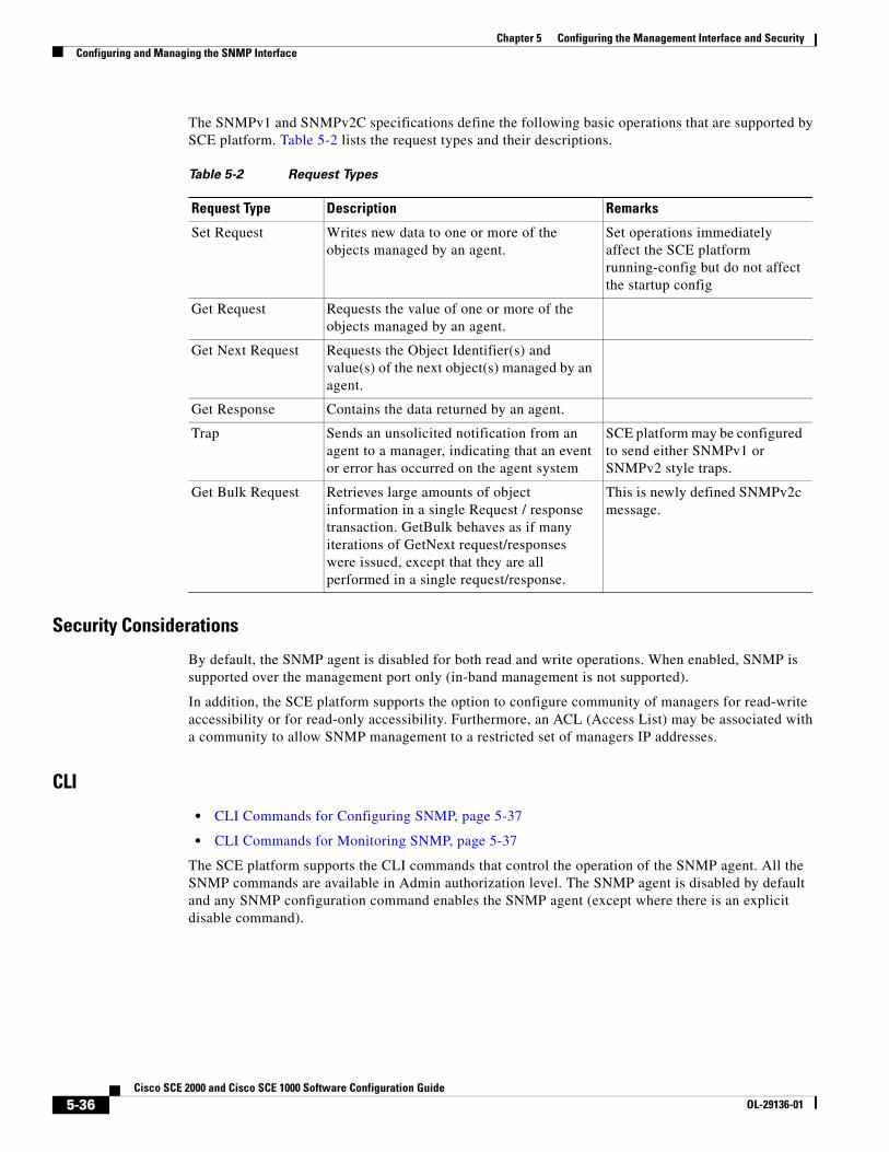
The SNMPv1 and SNMPv2C specifications define the following basic operations that are supported by SCE platform. Table 5-2 lists the request types and their descriptions.
Security Considerations
By default, the SNMP agent is disabled for both read and write operations. When enabled, SNMP is supported over the management port only (in-band management is not supported).
In addition, the SCE platform supports the option to configure community of managers for read-write accessibility or for read-only accessibility. Furthermore, an ACL (Access List) may be associated with a community to allow SNMP management to a restricted set of managers IP addresses.
CLI
• CLI Commands for Configuring SNMP, page 5-37
• CLI Commands for Monitoring SNMP, page 5-37
The SCE platform supports the CLI commands that control the operation of the SNMP agent. All the SNMP commands are available in Admin authorization level. The SNMP agent is disabled by default and any SNMP configuration command enables the SNMP agent (except where there is an explicit disable command).
Table 5-2 Request Types
Request Type Description Remarks
Set Request Writes new data to one or more of the objects managed by an agent.
Set operations immediately affect the SCE platform running-config but do not affect the startup config
Get Request Requests the value of one or more of the objects managed by an agent.
Get Next Request Requests the Object Identifier(s) and value(s) of the next object(s) managed by an agent.
Get Response Contains the data returned by an agent.
Trap Sends an unsolicited notification from an agent to a manager, indicating that an event or error has occurred on the agent system
SCE platform may be configured to send either SNMPv1 or SNMPv2 style traps.
Get Bulk Request Retrieves large amounts of object information in a single Request / response transaction. GetBulk behaves as if many iterations of GetNext request/responses were issued, except that they are all performed in a single request/response.
This is newly defined SNMPv2c message.
5-36Cisco SCE 2000 and Cisco SCE 1000 Software Configuration Guide
OL-29136-01
Chapter 5 Configuring the Management Interface and SecurityConfiguring and Managing the SNMP Interface
CLI Commands for Configuring SNMP
Following is a list of CLI commands available for configuring SNMP. These are Global Configuration mode commands.
• snmp-server enable
• no snmp-server
• [no] snmp-server community [all] [
• no | default] snmp-server enable traps
• [no] snmp-server host [all]
• [no] snmp-server contact
• [no] snmp-server location
CLI Commands for Monitoring SNMP
Following is a list of CLI commands available for monitoring SNMP. These are Viewer mode commands, and are available when the SNMP agent is enabled:
• show snmp (also available when SNMP agent is disabled)
• show snmp community
• show snmp contact
• show snmp enabled
• show snmp host
• show snmp location
• show snmp mib
• show snmp traps
MIBs
• MIB Data Objects, page 5-38
• Information About MIB-II, page 5-38
• Information About ENTITY-MIB, page 5-39
• Information About pcube Enterprise MIB, page 5-40
MIBs (Management Information Bases) are databases of objects that can be monitored by a network management system (NMS). SNMP uses standardized MIB formats that allow any SNMP tools to monitor any device defined by a MIB.
The SCE platform supports the following MIBs:
• Standard MIBs:
– MIB-II (as defined in RFC 1213, Management Information Base for Network Management of TCP/IP-based Internets) and some of its extensions.
– ENTITY-MIB version 2 (as defined in RFC 2737)
5-37Cisco SCE 2000 and Cisco SCE 1000 Software Configuration Guide
OL-29136-01

Chapter 5 Configuring the Management Interface and SecurityConfiguring and Managing the SNMP Interface
• Proprietary MIBs – Pcube enterprise MIBs defined by Cisco, for the Cisco Service Control products (see Proprietary MIB Reference, page B-1.).
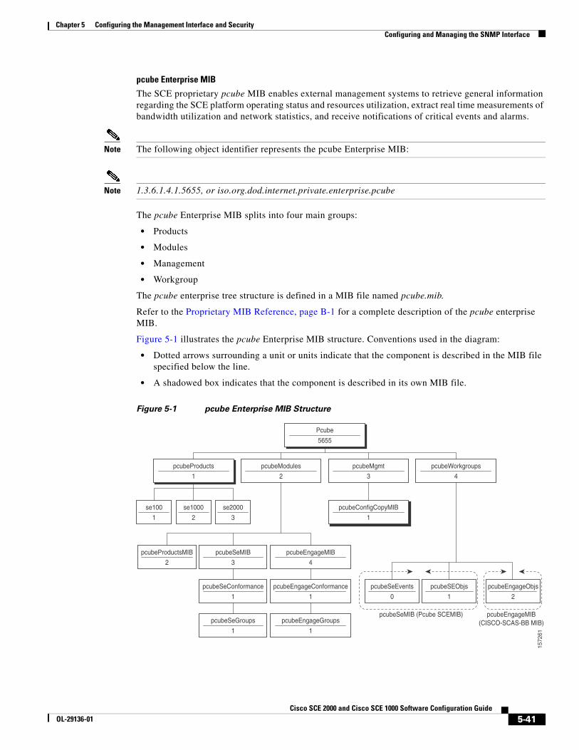
Pcube enterprise MIB (pcube) can be divided into different kinds of MIBs:
– Proprietary SCOS MIBs – These MIBs contain platform specific information. They also contain the generic definitions of the pcube subtree.
The SE MIB and the Dispatcher MIB are two examples of OS MIBs.
– Proprietary Application MIB(s) – These MIBs contain application specific information.
Currently, there is one application MIB – Engage MIB.
– Proprietary Common MIB(s) – These MIBs contain functionality that is common across more than a single Cisco platform.
Currently there is one common MIB – configuration copy MIB.
Since the acquisition of P-cube, Inc by Cisco Systems, Inc, the existing proprietary MIBs have undergone a process of updating to make them conform to Cisco standards. Note that all Pcube MIBs since SCOS version 3.0.3 are compiled using SMICNG and are in conformation with Cisco standards and styling.
Note While the designations "Pcube" and "SC” have been retained in the MIB for the sake of consistency, they refer to the corresponding Cisco SCE products.
MIB Data Objects
The data objects that make up the MIB may be identified in two ways:
• OID (Object Identifier) — The unique string that describes a specific data object in the agent database.
OIDs are written in dotted format such as: 1.3.6.1.4.1.5655.4.1.10.1
• MIB descriptor — A name defined in the MIB file for the OID. It is often used instead of the explicit OID.
For instance: “ifTable” stands for the OID of the MIB-II interface table.
Information About MIB-II
• MIB-II, page 5-38
• IF-MIB, page 5-38
MIB-II
SCE platform fully supports MIB-II (RFC1213), including the following groups
• System Interface (for both the management and line ports) AT (management port) IP (management port) ICMP (management port)
• TCP (management port)
• UDP (management port)
• SNMP (management port)
IF-MIB
The MIB-II standard has been extended by several different MIBs. The SCOS supports the IF-MIB, defined in RFC-2233.
5-38Cisco SCE 2000 and Cisco SCE 1000 Software Configuration Guide
OL-29136-01
Chapter 5 Configuring the Management Interface and SecurityConfiguring and Managing the SNMP Interface
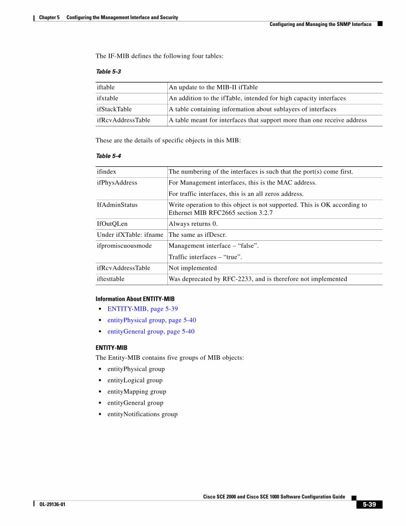
The IF-MIB defines the following four tables:
These are the details of specific objects in this MIB:
Information About ENTITY-MIB
• ENTITY-MIB, page 5-39
• entityPhysical group, page 5-40
• entityGeneral group, page 5-40
ENTITY-MIB
The Entity-MIB contains five groups of MIB objects:
• entityPhysical group
• entityLogical group
• entityMapping group
• entityGeneral group
• entityNotifications group
Table 5-3
iftable An update to the MIB-II ifTable
ifxtable An addition to the ifTable, intended for high capacity interfaces
ifStackTable A table containing information about sublayers of interfaces
ifRcvAddressTable A table meant for interfaces that support more than one receive address
Table 5-4
ifindex The numbering of the interfaces is such that the port(s) come first.
ifPhysAddress For Management interfaces, this is the MAC address.
For traffic interfaces, this is an all zeros address.
IfAdminStatus Write operation to this object is not supported. This is OK according to Ethernet MIB RFC2665 section 3.2.7
IfOutQLen Always returns 0.
Under ifXTable: ifname The same as ifDescr.
ifpromiscuousmode Management interface – “false”.
Traffic interfaces – “true”.
ifRcvAddressTable Not implemented
iftesttable Was deprecated by RFC-2233, and is therefore not implemented
5-39Cisco SCE 2000 and Cisco SCE 1000 Software Configuration Guide
OL-29136-01
Chapter 5 Configuring the Management Interface and SecurityConfiguring and Managing the SNMP Interface
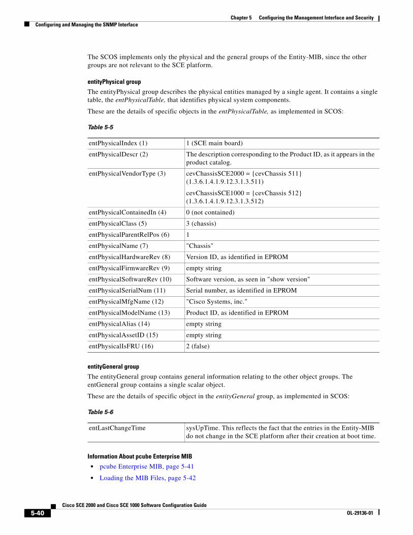
The SCOS implements only the physical and the general groups of the Entity-MIB, since the other groups are not relevant to the SCE platform.
entityPhysical group
The entityPhysical group describes the physical entities managed by a single agent. It contains a single table, the entPhysicalTable, that identifies physical system components.
These are the details of specific objects in the entPhysicalTable, as implemented in SCOS:
entityGeneral group
The entityGeneral group contains general information relating to the other object groups. The entGeneral group contains a single scalar object.
These are the details of specific object in the entityGeneral group, as implemented in SCOS:
Information About pcube Enterprise MIB
• pcube Enterprise MIB, page 5-41
• Loading the MIB Files, page 5-42
Table 5-5
entPhysicalIndex (1) 1 (SCE main board)
entPhysicalDescr (2) The description corresponding to the Product ID, as it appears in the product catalog.
entPhysicalVendorType (3) cevChassisSCE2000 = {cevChassis 511} (1.3.6.1.4.1.9.12.3.1.3.511)
cevChassisSCE1000 = {cevChassis 512} (1.3.6.1.4.1.9.12.3.1.3.512)
entPhysicalContainedIn (4) 0 (not contained)
entPhysicalClass (5) 3 (chassis)
entPhysicalParentRelPos (6) 1
entPhysicalName (7) "Chassis"
entPhysicalHardwareRev (8) Version ID, as identified in EPROM
entPhysicalFirmwareRev (9) empty string
entPhysicalSoftwareRev (10) Software version, as seen in "show version"
entPhysicalSerialNum (11) Serial number, as identified in EPROM
entPhysicalMfgName (12) "Cisco Systems, inc."
entPhysicalModelName (13) Product ID, as identified in EPROM
entPhysicalAlias (14) empty string
entPhysicalAssetID (15) empty string
entPhysicalIsFRU (16) 2 (false)
Table 5-6
entLastChangeTime sysUpTime. This reflects the fact that the entries in the Entity-MIB do not change in the SCE platform after their creation at boot time.
5-40Cisco SCE 2000 and Cisco SCE 1000 Software Configuration Guide
OL-29136-01
Chapter 5 Configuring the Management Interface and SecurityConfiguring and Managing the SNMP Interface
pcube Enterprise MIB
The SCE proprietary pcube MIB enables external management systems to retrieve general information regarding the SCE platform operating status and resources utilization, extract real time measurements of bandwidth utilization and network statistics, and receive notifications of critical events and alarms.
Note The following object identifier represents the pcube Enterprise MIB:
Note 1.3.6.1.4.1.5655, or iso.org.dod.internet.private.enterprise.pcube
The pcube Enterprise MIB splits into four main groups:
• Products
• Modules
• Management
• Workgroup
The pcube enterprise tree structure is defined in a MIB file named pcube.mib.
Refer to the Proprietary MIB Reference, page B-1 for a complete description of the pcube enterprise MIB.
Figure 5-1 illustrates the pcube Enterprise MIB structure. Conventions used in the diagram:
• Dotted arrows surrounding a unit or units indicate that the component is described in the MIB file specified below the line.
• A shadowed box indicates that the component is described in its own MIB file.
Figure 5-1 pcube Enterprise MIB Structure
Pcube
5655
pcubeProducts
1
se2000
3
se1000
2
se100
1
pcubeModules
2
pcubeMgmt
3
pcubeConfigCopyMIB
1
pcubeEngageMIB
4
pcubeSeMIB
3
pcubeEngageConformance
1
pcubeSeConformance
1
pcubeEngageGroups
1
pcubeSeGroups
1
pcubeProductsMIB
2
pcubeWorkgroups
4
pcubeEngageObjs
2
pcubeSEObjs
pcubeSeMIB (Pcube SCEMIB) pcubeEngageMIB(CISCO-SCAS-BB MIB)
1
pcubeSeEvents
0
162751
5-41Cisco SCE 2000 and Cisco SCE 1000 Software Configuration Guide
OL-29136-01
Chapter 5 Configuring the Management Interface and SecurityConfiguring and Managing the SNMP Interface
• pcubeProducts subtree — contains the OIDs of Cisco Service Control products.
• pcubeModules subtree — provides a root object identifier under which MIB modules can be defined.
• pcubeMgmt subtree — the root for pcube MIBs that are relevant to multiple products.
– pcubeConfigCopyMIB — a subset of the Cisco Config-Copy-MIB that supports local copying of running config to startup config.
• pcubeWorkgroups subtree — contains the actual MIBs for Cisco Service Control devices and sub-devices.
• pcubeSeMIB — comprises two branches:
– pcubeSeEvents — Contains the OIDs used for sending enterprise-specific notifications.
– pcubeSEObjs — Contains the OIDs that belong to the SCE platform, divided into groups according to functionality.
Loading the MIB Files
The Service Control proprietary MIB uses definitions that are defined in other MIBs, such as pcube MIB (pcube.mib ), and the SNMPv2.mib. Therefore, the order in which the MIBs are loaded is important. To avoid errors, the MIBs must be loaded in the proper order.
1. Load SNMPv2.my.
2. Load SNMP-FRAMEWORK-MIB.my.
3. Load PCUBE-SMI.my.
4. Load PCUBE-SE-MIB.my.
Note Information and proprietary MIB files supported by the SCOS can be downloaded from www.cisco.com under Cisco Service Routing Products section.
Configuration via SNMP
SCE platform supports a limited set of variables that may be configured via SNMP (read-write variables). Setting a variable via SNMP (as via the CLI) takes effect immediately and affects only the running-configuration. To make this configuration stored for next reboots (startup-configuration) the user must specify it explicitly via CLI or via SNMP using the Cisco enterprise MIB objects (see Figure 5-1pcube Enterprise MIB Structure, page 5-41).
It should be noted also that the SCE platform takes the approach of a single configuration database with multiple interfaces that may change this database. Therefore, executing the copy running-config startup-config command via CLI or SNMP makes permanent all the changes made by either SNMP or CLI.
Configuring the SNMP Community Strings • How to Define a Community String, page 5-43
• How to Remove a Community String, page 5-43
• How to Display the Configured Community Strings, page 5-44
To enable SNMP management, you must configure SNMP community strings to define the relationship between the SNMP manager and the agent.
5-42Cisco SCE 2000 and Cisco SCE 1000 Software Configuration Guide
OL-29136-01
Chapter 5 Configuring the Management Interface and SecurityConfiguring and Managing the SNMP Interface
After receiving an SNMP request, the SNMP agent compares the community string in the request to the community strings that are configured for the agent. The requests are valid under the following circumstances:
• SNMP Get, Get-next, and Get-bulk requests are valid if the community string in the request matches the read-only community.
• SNMP Get, Get-next, Get-bulk and Set requests are valid if the community string in the request matches the agent’s read-write community.
How to Define a Community String
• Options, page 5-43
• Defining a Community String: Example, page 5-43
Options
The following options are available:
• community-string — a security string that identifies a community of managers who are permitted to access the SNMP server
• acl-number — ID number if the Access Control List to be assigned to the SNMP interface. It should list the IP addresses of the SNMP managers permitted to use the community string to gain access to the agent.
If no ACL is specified, all IP addresses can access the agent using the defined community string. For more information about ACLs, see Configuring Access Control Lists (ACLs), page 5-27
The following keywords are available:
• ro — read only (default accessibility)
• rw — read and write
Step 1 From the SCE(config)# prompt, type snmp-server community community-string ro|rw acl-number and press Enter.
Repeat the command as necessary to define all community strings.
Defining a Community String: Example
This example shows how to configure a community string called “mycommunity” with read-only rights and access list number “1”.
Since read-only is the default, it does not need to be defined explicitly.
SCE(config)#snmp-server community mycommunity 1
How to Remove a Community String
Step 1 From the SCE(config)# prompt, type no snmp-server community community-string and press Enter.
5-43Cisco SCE 2000 and Cisco SCE 1000 Software Configuration Guide
OL-29136-01
Chapter 5 Configuring the Management Interface and SecurityConfiguring and Managing the SNMP Interface
Removing a Community String: Example
The following example shows how to remove a community string called “mycommunity”.
SCE(config)#no snmp-server community mycommunity
How to Display the Configured Community Strings
Step 1 From the SCE> prompt, type show snmp-server community community-string and press Enter.
Displaying the Configured Community Strings: Example
The following example shows how to display the configured SNMP communities.
SCE>show snmp communityCommunity: public, Access Authorization: RO, Access List Index: 1SCE>
Configuring SNMP Notifications Use these commands to configure:
• The destinations that will receive SNMP notifications (hosts)
• Which types of notifications will be sent (traps)
About SNMP Notifications
Notifications are unsolicited messages that are generated by the SNMP agent that resides inside the SCE platform when an event occurs. When the Network Management System receives the notification message, it can take suitable actions, such as logging the occurrence or ignoring the signal.
By default, the SCE platform is not configured to send any SNMP notifications. You must define the Network Management System to which the SCE platform should send notifications. (See the table below, Configurable Notifications, for a list of configurable notifications). Whenever one of the events that trigger notifications occurs in the SCE platform, an SNMP notification is sent from the SCE platform to the list of IP addresses that you define.
SCE platform supports two general categories of notifications:
• Standard SNMP notifications — As defined in RFC1157 and using the conventions defined in RFC1215.
• Proprietary SCE enterprise notifications — As defined in the SCE proprietary MIB.
After a host or hosts are configured to receive notifications, by default, the SCE platform sends to the host or hosts all the notifications supported by the SCE platform except for the AuthenticationFailure notification. The SCE platform provides the option to enable or disable the sending of this notification, as well as some of the SCE enterprise notifications, explicitly.
SCE platform can be configured to generate either SNMPv1 style or SNMPv2c style notifications. By default, the SCE platforms sends SNMPv1 notifications.
5-44Cisco SCE 2000 and Cisco SCE 1000 Software Configuration Guide
OL-29136-01
Chapter 5 Configuring the Management Interface and SecurityConfiguring and Managing the SNMP Interface
Following are some sample procedures illustrating how to do the following:
• Configure hosts (NMS) to which the SNMP agent should send notifications
• Remove/disable a host (NMS) from receiving notifications
• Enable the SNMP agent to send authentication-failure notifications
• Enable the SNMP agent to send enterprise notifications
• Reset all notifications to the default setting
How to Define SNMP Hosts
Use the snmp-server host command to define the hosts that will receive notifications from the SCE platform.
• Options, page 5-45
• How to Configure the SCE Platform to Send Notifications to a Host (NMS), page 5-45
• How to Configure the SCE Platform to Stop Sending Notifications to a Host, page 5-46
• How to Configure SNMP Traps, page 5-46
Options
The following options are available:
• ip-address — the IP address of the SNMP server host
• community-string — a security string that identifies a community of managers who are permitted to access the SNMP server
• version — SNMP version running in the system. Can be set to 1 or 2c.
– Default — 1 (SNMPv1)
How to Configure the SCE Platform to Send Notifications to a Host (NMS)
Step 1 At the SCE(config)# prompt, type snmp-server host ip-address community-string and press Enter.
If the version is not specified, SNMPv1 is assumed.
Only one host can be specified per command. To define multiple hosts, execute one command for each host.
Configuring the SCE Platform to Send Notifications to Multiple Hosts: Example
The following example shows how to configure the SCE platform to send SNMPv1 notifications to several hosts.
SCE(config)#snmp-server host 10.10.10.10 mycommunitySCE(config)#snmp-server host 20.20.20.20 mycommunitySCE(config)#snmp-server host 30.30.30.30 mycommunitySCE(config)#snmp-server host 40.40.40.40 mycommunity
5-45Cisco SCE 2000 and Cisco SCE 1000 Software Configuration Guide
OL-29136-01

Chapter 5 Configuring the Management Interface and SecurityConfiguring and Managing the SNMP Interface
How to Configure the SCE Platform to Stop Sending Notifications to a Host
Step 1 At the SCE(config)# prompt, type no snmp-server host ip-address and press Enter.
Configuring the SCE Platform to Stop Sending Notifications to a Host: Example
The following example shows how to remove the host with the IP Address: “192.168.0.83”.
SCE(config)#no snmp-server host 192.168.0.83
How to Configure SNMP Traps
Use this command to configure the notifications that will be sent to the defined host.
• Options, page 5-46
• How to Enable the SNMP Server to Send Authentication Failure Notifications, page 5-47
• How to Enable the SNMP Server to Send All Enterprise Notifications, page 5-47
• How to Enable the SNMP Server to Send a Specific Enterprise Notification, page 5-47
• How to Restore All the Notifications to the Default Status, page 5-47
Options
The following options are available:
• snmp — optional parameter that specifies that all or specific snmp traps should be enabled or disabled.
By default, snmp traps are disabled.
snmp trap name — optional parameter that specifies a specific snmp trap that should be enabled or disabled.
Currently the only accepted value for this parameter is Authentication.
• enterprise — optional parameter that specifies that all or specific enterprise traps should be enabled or disabled.
By default, enterprise traps are enabled.
• enterprise trap name — optional parameter that specifies a specific snmp trap that should be enabled or disabled.
Values: attack, chassis, link-bypass, logger, operational-status, port-operational-status, pull-request-failure, RDR-formatter, session, SNTP, subscriber, system-reset, telnet, vas-traffic-forwarding
Use these parameters as follows:
• To enable/disable all traps of one type: Specify only snmp or enterprise.
• To enable/disable only one specific trap: Specify snmp or enterprise with the additional trap name parameter naming the desired trap.
• To enable/disable all traps: Do not specify either snmp or enterprise.
5-46Cisco SCE 2000 and Cisco SCE 1000 Software Configuration Guide
OL-29136-01

Chapter 5 Configuring the Management Interface and SecurityConfiguring and Managing the SNMP Interface
How to Enable the SNMP Server to Send Authentication Failure Notifications
Step 1 At the SCE(config)# prompt, type snmp-server enable traps snmp authentication and press Enter.
How to Enable the SNMP Server to Send All Enterprise Notifications
Step 1 At the SCE(config)# prompt, type snmp-server enable traps enterprise and press Enter.
How to Enable the SNMP Server to Send a Specific Enterprise Notification
Step 1 At the SCE(config)# prompt, type snmp-server enable traps enterprise [attack|chassis|link-bypass|logger|operational-status|port-operational-status|pull-request-failure|RDR-formatter|session| SNTP|subscriber|system-reset|telnet|vas-traffic-forwarding] and press Enter.
Specify the desired enterprise trap type.
Enabling the SNMP Server to Send a Specific Enterprise Notification: Example
The following example shows how to configure the SNMP server to send the logger enterprise notification only.
SCE(config)#snmp-server enable traps enterprise logger
How to Restore All the Notifications to the Default Status
Step 1 At the SCE(config)# prompt, type default snmp-server enable traps and press Enter.
Resets all notifications supported by the SCE platform to their default status.
5-47Cisco SCE 2000 and Cisco SCE 1000 Software Configuration Guide
OL-29136-01

Chapter 5 Configuring the Management Interface and SecurityManaging Passwords
Managing Passwords • About Passwords, page 5-48
• Changing Your Password, page 5-48
• Password Encryption, page 5-49
• Password Recovery, page 5-50
About Passwords Cisco CLI passwords are an access-level authorization setting, not individual user passwords. All Admin users, for example, log in with the same password. This means that the system does not identify you as an individual, but as a user with certain privileges.
Passwords are needed for all authorization levels to prevent unauthorized users from accessing the SCE platform. It is highly recommended that you change the default password upon initial installation, and that you change the passwords periodically to secure the system.
Note The default password for all levels is “Cisco”.
When a telnet user logs on, he sees only a Password: prompt, no logo is displayed. This provides extra security by not revealing the system identity to users that do not know the password.
Password guidelines:
• Password length must be between 4 and 100 characters long.
• Passwords can contain any visible keyboard character.
• Passwords must begin with a letter.
• Passwords cannot contain spaces.
• Passwords are case-sensitive.
Users with Admin or higher authorization level can view the configured passwords using the show running-config or the show startup-config commands. Therefore, if you want passwords to remain completely confidential, you must activate the encryption feature, described in How to Enable Password Encryption, page 5-50.
Changing Your Password • How to Change Your Password, page 5-48
• Verifying that the Password has been Successfully Changed, page 5-49
How to Change Your Password
Use the enable password command to change the password. Note that if the password has been changed, the default password will no longer be accepted.
5-48Cisco SCE 2000 and Cisco SCE 1000 Software Configuration Guide
OL-29136-01

Chapter 5 Configuring the Management Interface and SecurityManaging Passwords
Options
The following options are available:
• level — the number of the authorization level for which the password is defined.
The authorization levels are:
– 0: user
– 5: viewer
– 10: admin
– 15: root
• password — the new password for the specified authorization level.
Step 1 At the SCE(config)# prompt type enable password level level password and press Enter.
The Network Administrator should record passwords in a secure location.
Verifying that the Password has been Successfully Changed
Step 1 Initiate a new telnet connection, while maintaining the one you used to set the password.
This is important so that if the verification fails, you would still have admin level authorization to re-enter the password.
Step 2 At the SCE# prompt type enable level and press Enter.
Specify the level for which you have just changed the password.
Step 3 At the prompt, type your new password and press Enter.
If your new password has been entered successfully, then the appropriate prompt appears.
If you enter an incorrect password, the password prompt will appear again.
Repeat these steps as necessary to check additional passwords.
The encryption feature will encrypt the passwords in the platform configuration files.
Password Encryption • How to Enable Password Encryption, page 5-50
• How to Disable Password Encryption, page 5-50
Once the encryption feature is activated, passwords entered into the system are encrypted to the startup configuration file the next time the configuration is saved. When encryption feature is turned off, passwords previously encrypted to the startup configuration file are not deciphered.
By default, the password encryption feature is disabled.
5-49Cisco SCE 2000 and Cisco SCE 1000 Software Configuration Guide
OL-29136-01
Chapter 5 Configuring the Management Interface and SecurityManaging Passwords
How to Enable Password Encryption
Step 1 From the sce(config)# prompt, type service password encryption and press Enter.
How to Disable Password Encryption
Step 1 From the sce(config)# prompt, type no service password encryption and press Enter.
This does not remove the encryption from the configuration file. You must save to the startup configuration file if you want the password to be stored un-encrypted on the startup configuration file.
Password Recovery Use the following procedures if it becomes necessary to recover the enable passwords for the SCE platform. Be sure to use the appropriate procedure depending on the version of SCOS you are using:
• Releases before 2.5.5
• Release 2.5.5 or later
How to Recover Passwords: Cisco SCOS Release 2.5.5 and Earlier
The procedure used for recovering the passwords depends on whether or not there are user-configured parameters that need to be saved:
• How to Recover Passwords: Reverting to the Default Configuration, page 5-50
• How to Recover Passwords: Saving the Current Configuration, page 5-51
How to Recover Passwords: Reverting to the Default Configuration
For Cisco SCE platforms running a Cisco SCOS version before Release 2.5.5, you can recover the passwords by simply removing the config.txt file and then rebooting.
Note This procedure resets the configuration of the Cisco SCE platform to factory defaults. Therefore, this procedure should be performed only after making sure that no traffic can be affected by the behavior of the Cisco SCE platform.
Note This procedure resets the configuration of the Cisco SCE platform to factory defaults. Therefore, all current user configuration is lost. To recover the passwords without losing the user configuration, use the procedure described in How to Recover Passwords: Saving the Current Configuration, page 5-51
Step 1 Connect a serial terminal to the ‘AUX’ port at 9600 baud.
Step 2 Press Enter so that the prompt appears.
Connects to the SCE platform.
5-50Cisco SCE 2000 and Cisco SCE 1000 Software Configuration Guide
OL-29136-01

Chapter 5 Configuring the Management Interface and SecurityManaging Passwords
Step 3 Type rm "/tffs0/system/config.txt" and press Enter.
Deletes the configuration file, which contains the unknown passwords.
Step 4 Type reboot and press Enter.
Reboot the system to restore the default configuration, including default passwords.
Note To block unauthorized users from connecting to the SCE platform using the default password, a new password should be configured immediately for all levels for which such a password is required. The configuration should be saved (use the CLI command copy running-config startup-config ) to make the new passwords permanent.
How to Recover Passwords: Saving the Current Configuration
Simply deleting the config.txt file, while quick and easy to do, resets the configuration of the SCE platform to factory defaults, replacing all current user configuration. Use this procedure, which saves the configuration file, to recover the passwords without losing the current configuration.
Note Although this procedure does save the current configuration, the process involves a temporary reset of the configuration of the SCE platform to factory defaults. Therefore, this procedure should be performed only after making sure that no traffic can be affected by the behavior of the SCE platform.
Step 1 Connect a serial terminal to the ‘AUX’ port at 9600 baud.
Step 2 Press Enter so that the prompt appears.
Connects to the SCE platform.
Step 3 Type cd system and press Enter.
Navigates to the system directory.
Step 4 Type rename "config.txt" "config2.txt" and press Enter.
Renames the configuration file so that it will not be lost when the system is rebooted.
Step 5 Type reboot and press Enter.
Reboots the system to reset passwords. The default configuration is restored, in which all passwords are Cisco. This will provide access to the system.
(The IP address configuration remains as it was last configured.)
Step 6 Establish a Telnet session to the SCE platform and enable the admin authorization level.
Use the default password (Cisco).
Step 7 At the SCE# prompt type copy /system/config2.txt ftp:// <user>:<ftp_password>@ip_address/<path>/config2.txt and press Enter.
Copies the file /system/config2.txt to the workstation using the SCE platform FTP client.
5-51Cisco SCE 2000 and Cisco SCE 1000 Software Configuration Guide
OL-29136-01

Chapter 5 Configuring the Management Interface and SecurityManaging Passwords
Step 8 On the workstation, open the file. Look for the lines that start with enable password.
If passwords are not encrypted, you will be able to see the passwords, and can simply take note of them.
If passwords are encrypted, do the following
a. Edit the file by removing the lines that begin with enable password.
b. Save the file.
c. At the SCE# prompt, type copy ftp:// <user>:<ftp_password>@ip_address/<path>/config2.txt /system/config2.txt and press Enter.
Copies the file from the workstation back to the SCE platform disk space using the SCE platform FTP client.
Step 9 At the SCE# prompt, type rename /system/config2.txt /system/config.txt and press Enter.
Renames the configuration file on the SCE platform back to the original name config.txt.
Step 10 At the SCE# prompt, type reload and press Enter.
Reboots the SCE platform to restore the saved user configuration
• If passwords were not encrypted—the user-configured passwords that you viewed in the copied file are restored, since the configuration file was not changed.
• If passwords were encrypted—the default password Cisco remains, since the encrypted lines were removed from the configuration file before it was copied back to the SCE platform.
To block unauthorized users from connecting to the SCE platform using the default password, a new password should be configured immediately for all levels for which such a password is required. The configuration should be saved (use the CLI command copy running-config startup-config ) to make the new passwords permanent.
How to Recover Passwords: Cisco SCOS Release 2.5.5 and later
In Cisco SCOS versions 2.5.5 and later, a specific command is available to restore the default passwords. However, it is important to note that this default password configuration is only temporary. New passwords should be configured and saved immediately both for security and also so that the unknown passwords will not be restored in case of system reboot.
Note This procedure does not affect configuration parameters other then login passwords. It is, therefore, safe to execute during traffic control.
Step 1 Connect a serial terminal to the ‘AUX’ port at 9600 baud.
Step 2 Press Enter so that the prompt appears.
Connects to the SCE platform.
5-52Cisco SCE 2000 and Cisco SCE 1000 Software Configuration Guide
OL-29136-01

Chapter 5 Configuring the Management Interface and SecurityManaging Passwords
Step 3 At the prompt, type PSWD_ResetAll and press Enter.
Resets the enable passwords.
The following message will appear:
All 'enable' passwords have been reset.
The SCOS is now using the default passwords for all levels. Note that this is a temporary state that is not preserved after a reboot. Rebooting the SCE platform without changing and saving the passwords will restore the unknown passwords.
n order to block unauthorized users from connecting to the SCE platform using the default password, a new password should be configured immediately for all levels for which such a password is required. The configuration should be saved (use the CLI command copy running-config startup-config ) to make the new passwords permanent.
5-53Cisco SCE 2000 and Cisco SCE 1000 Software Configuration Guide
OL-29136-01

Chapter 5 Configuring the Management Interface and SecurityIP Configuration
IP Configuration • Configuring the IP Routing Table, page 5-54
• IP Advertising, page 5-56
• Configuring the IP Address of the Management Interface, page 5-57
Configuring the IP Routing Table • How to Configure the Default Gateway, page 5-54
• How to Add an Entry to the IP Routing Table, page 5-55
• Displaying the IP Routing Table, page 5-55
For handling IP packets on the out-of-band MNG port, the SCE platform maintains a static routing table. When a packet is sent, the system checks the routing table for proper routing, and forwards the packet accordingly. In cases where the SCE platform cannot determine where to route a packet, it sends the packet to the default gateway.
SCE platform supports the configuration of the default gateway as the default next hop router, as well as the configuration of the routing table to provide different next hop routers for different subnets (for maximum configuration of 100 subnets).
The following sections illustrate how to use CLI commands to configure various parameters.
The following commands are relevant to IP routing tables:
• ip default-gateway
• ip route prefix mask next-hop
• no ip route all
• no ip route prefix mask
• show ip route
• show ip route prefix
• show ip route prefix mask
How to Configure the Default Gateway
• Options, page 5-54
• Configuring the Default Gateway: Example, page 5-55
Options
The following option is available:
• ip-address—the IP address of the default gateway.
Step 1 From the SCE(config)# prompt, type ip default-gateway ip-address, and press Enter.
Enables privileged EXEC mode.
• Enter your password if prompted.
5-54Cisco SCE 2000 and Cisco SCE 1000 Software Configuration Guide
OL-29136-01
Chapter 5 Configuring the Management Interface and SecurityIP Configuration
Configuring the Default Gateway: Example
The following example shows how to set the default gateway IP of the SCE platform to 10.1.1.1.
SCE(config)#ip default-gateway 10.1.1.1
How to Add an Entry to the IP Routing Table
• Options, page 5-55
• How to Add an Entry to the IP Routing Table: Example, page 5-55
Options
The following options are available:
• prefix — IP address of the routing entry, in dotted notation.
• mask — The relevant subnet mask, in dotted notation
• next-hop — The IP address of the next hop in the route, in dotted notation.
Must be within the MNG interface subnet.
Step 1 From the SCE(config)# prompt, type ip route prefix mask next-hop, and press Enter.
Adds the specified IP routing entry to the routing table.
How to Add an Entry to the IP Routing Table: Example
The following example shows how to set the router 10.1.1.250 as the next hop to subnet 10.2.0.0.
SCE(config)#ip route 10.2.0.0 255.255.0.0 10.1.1.250
Displaying the IP Routing Table
• How to Display the Entire IP Routing Table, page 5-55
• How to Display the IP Routing Table for a Specified Subnet, page 5-56
How to Display the Entire IP Routing Table
Step 1 From the SCE# prompt, type show ip route and press Enter.
Displays the entire routing table and the destination of last resort (default-gateway)
Displaying the Entire IP Routing Table: Example
This example shows how to display the routing table.
SCE#show ip routegateway of last resort is 10.1.1.1| prefix | mask | next hop ||-----------------|------------------|-----------------|| 10.2.0.0 | 255.255.0.0 | 10.1.1.250 || 10.3.0.0 | 255.255.0.0 | 10.1.1.253 || 198.0.0.0 | 255.0.0.0 | 10.1.1.251 || 10.1.60.0 | 255.255.255.0 | 10.1.1.5 |
5-55Cisco SCE 2000 and Cisco SCE 1000 Software Configuration Guide
OL-29136-01
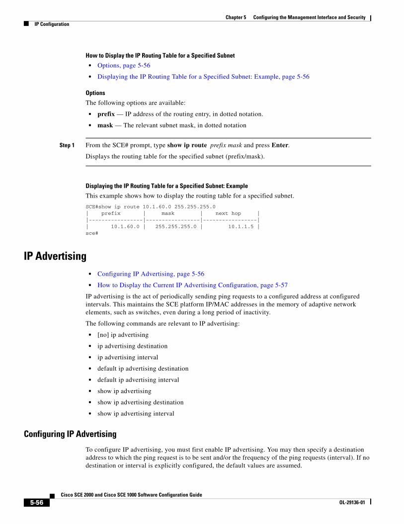
Chapter 5 Configuring the Management Interface and SecurityIP Configuration
How to Display the IP Routing Table for a Specified Subnet
• Options, page 5-56
• Displaying the IP Routing Table for a Specified Subnet: Example, page 5-56
Options
The following options are available:
• prefix — IP address of the routing entry, in dotted notation.
• mask — The relevant subnet mask, in dotted notation
Step 1 From the SCE# prompt, type show ip route prefix mask and press Enter.
Displays the routing table for the specified subnet (prefix/mask).
Displaying the IP Routing Table for a Specified Subnet: Example
This example shows how to display the routing table for a specified subnet.
SCE#show ip route 10.1.60.0 255.255.255.0| prefix | mask | next hop ||-----------------|-----------------|-----------------|| 10.1.60.0 | 255.255.255.0 | 10.1.1.5 |sce#
IP Advertising • Configuring IP Advertising, page 5-56
• How to Display the Current IP Advertising Configuration, page 5-57
IP advertising is the act of periodically sending ping requests to a configured address at configured intervals. This maintains the SCE platform IP/MAC addresses in the memory of adaptive network elements, such as switches, even during a long period of inactivity.
The following commands are relevant to IP advertising:
• [no] ip advertising
• ip advertising destination
• ip advertising interval
• default ip advertising destination
• default ip advertising interval
• show ip advertising
• show ip advertising destination
• show ip advertising interval
Configuring IP Advertising
To configure IP advertising, you must first enable IP advertising. You may then specify a destination address to which the ping request is to be sent and/or the frequency of the ping requests (interval). If no destination or interval is explicitly configured, the default values are assumed.
5-56Cisco SCE 2000 and Cisco SCE 1000 Software Configuration Guide
OL-29136-01
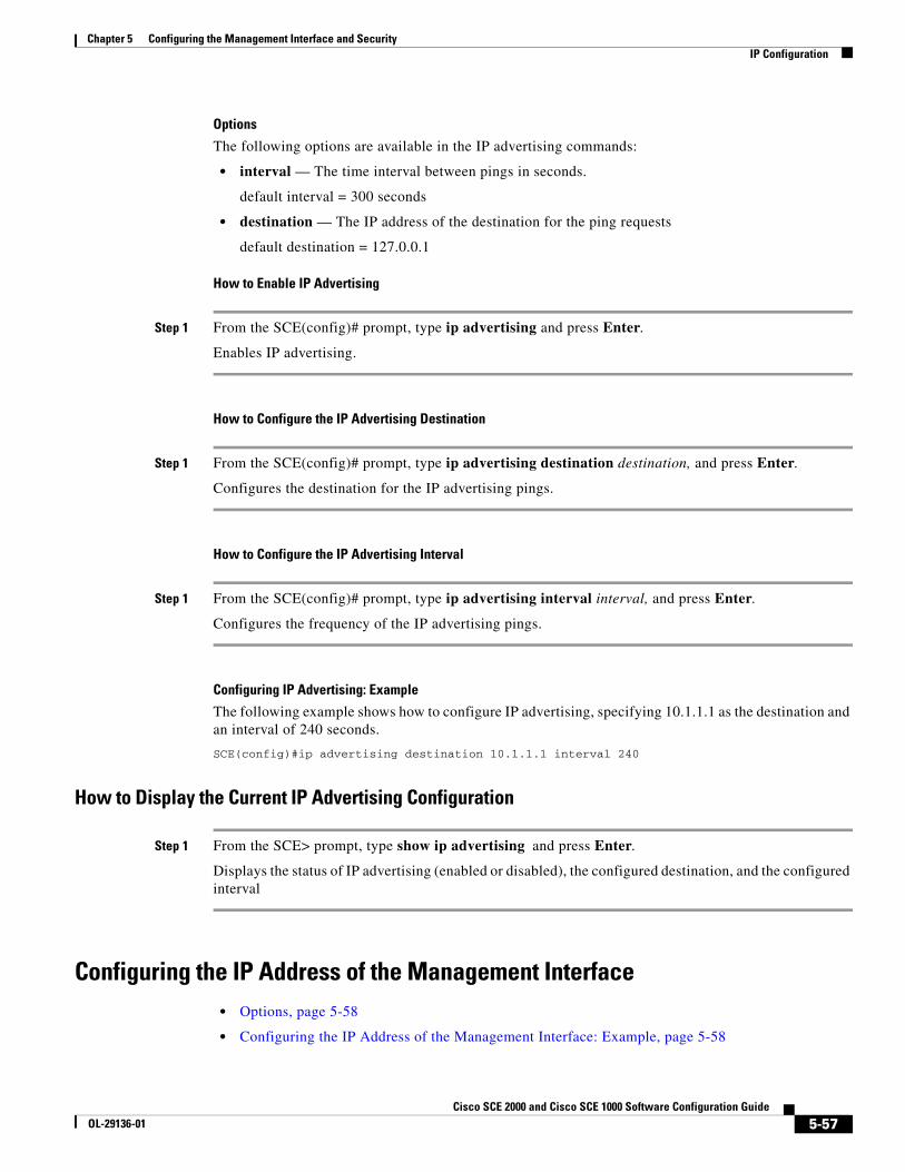
Chapter 5 Configuring the Management Interface and SecurityIP Configuration
Options
The following options are available in the IP advertising commands:
• interval — The time interval between pings in seconds.
default interval = 300 seconds
• destination — The IP address of the destination for the ping requests
default destination = 127.0.0.1
How to Enable IP Advertising
Step 1 From the SCE(config)# prompt, type ip advertising and press Enter.
Enables IP advertising.
How to Configure the IP Advertising Destination
Step 1 From the SCE(config)# prompt, type ip advertising destination destination, and press Enter.
Configures the destination for the IP advertising pings.
How to Configure the IP Advertising Interval
Step 1 From the SCE(config)# prompt, type ip advertising interval interval, and press Enter.
Configures the frequency of the IP advertising pings.
Configuring IP Advertising: Example
The following example shows how to configure IP advertising, specifying 10.1.1.1 as the destination and an interval of 240 seconds.
SCE(config)#ip advertising destination 10.1.1.1 interval 240
How to Display the Current IP Advertising Configuration
Step 1 From the SCE> prompt, type show ip advertising and press Enter.
Displays the status of IP advertising (enabled or disabled), the configured destination, and the configured interval
Configuring the IP Address of the Management Interface • Options, page 5-58
• Configuring the IP Address of the Management Interface: Example, page 5-58
5-57Cisco SCE 2000 and Cisco SCE 1000 Software Configuration Guide
OL-29136-01
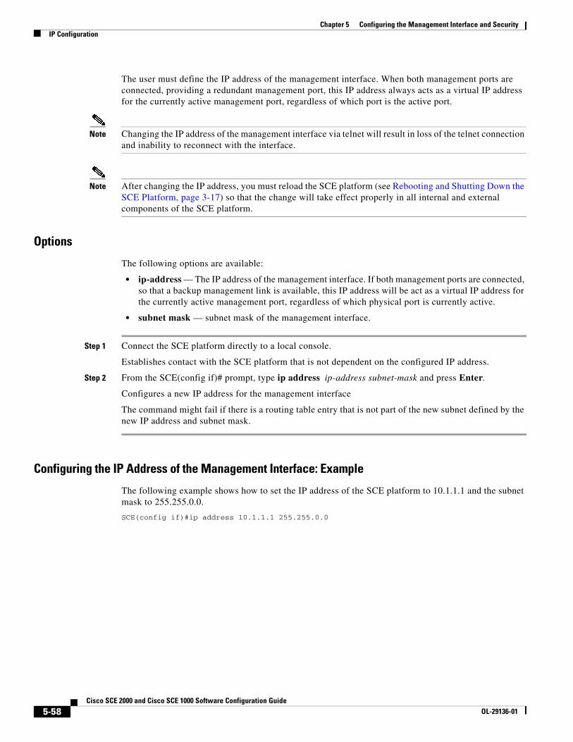
Chapter 5 Configuring the Management Interface and SecurityIP Configuration
The user must define the IP address of the management interface. When both management ports are connected, providing a redundant management port, this IP address always acts as a virtual IP address for the currently active management port, regardless of which port is the active port.
Note Changing the IP address of the management interface via telnet will result in loss of the telnet connection and inability to reconnect with the interface.
Note After changing the IP address, you must reload the SCE platform (see Rebooting and Shutting Down the SCE Platform, page 3-17) so that the change will take effect properly in all internal and external components of the SCE platform.
Options
The following options are available:
• ip-address — The IP address of the management interface. If both management ports are connected, so that a backup management link is available, this IP address will be act as a virtual IP address for the currently active management port, regardless of which physical port is currently active.
• subnet mask — subnet mask of the management interface.
Step 1 Connect the SCE platform directly to a local console.
Establishes contact with the SCE platform that is not dependent on the configured IP address.
Step 2 From the SCE(config if)# prompt, type ip address ip-address subnet-mask and press Enter.
Configures a new IP address for the management interface
The command might fail if there is a routing table entry that is not part of the new subnet defined by the new IP address and subnet mask.
Configuring the IP Address of the Management Interface: Example
The following example shows how to set the IP address of the SCE platform to 10.1.1.1 and the subnet mask to 255.255.0.0.
SCE(config if)#ip address 10.1.1.1 255.255.0.0
5-58Cisco SCE 2000 and Cisco SCE 1000 Software Configuration Guide
OL-29136-01
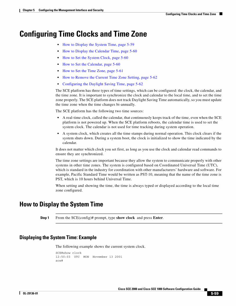
Chapter 5 Configuring the Management Interface and SecurityConfiguring Time Clocks and Time Zone
Configuring Time Clocks and Time Zone • How to Display the System Time, page 5-59
• How to Display the Calendar Time, page 5-60
• How to Set the System Clock, page 5-60
• How to Set the Calendar, page 5-60
• How to Set the Time Zone, page 5-61
• How to Remove the Current Time Zone Setting, page 5-62
• Configuring the Daylight Saving Time, page 5-62
The SCE platform has three types of time settings, which can be configured: the clock, the calendar, and the time zone. It is important to synchronize the clock and calendar to the local time, and to set the time zone properly. The SCE platform does not track Daylight Saving Time automatically, so you must update the time zone when the time changes bi-annually.
The SCE platform has the following two time sources:
• A real-time clock, called the calendar, that continuously keeps track of the time, even when the SCE platform is not powered up. When the SCE platform reboots, the calendar time is used to set the system clock. The calendar is not used for time tracking during system operation.
• A system clock, which creates all the time stamps during normal operation. This clock clears if the system shuts down. During a system boot, the clock is initialized to show the time indicated by the calendar.
It does not matter which clock you set first, as long as you use the clock and calendar read commands to ensure they are synchronized.
The time zone settings are important because they allow the system to communicate properly with other systems in other time zones. The system is configured based on Coordinated Universal Time (UTC), which is standard in the industry for coordination with other manufacturers’ hardware and software. For example, Pacific Standard Time would be written as PST-10, meaning that the name of the time zone is PST, which is 10 hours behind Universal Time.
When setting and showing the time, the time is always typed or displayed according to the local time zone configured.
How to Display the System Time
Step 1 From the SCE(config)# prompt, type show clock and press Enter.
Displaying the System Time: Example
The following example shows the current system clock.
SCE#show clock12:50:03 UTC MON November 13 2001sce#
5-59Cisco SCE 2000 and Cisco SCE 1000 Software Configuration Guide
OL-29136-01
Chapter 5 Configuring the Management Interface and SecurityConfiguring Time Clocks and Time Zone
How to Display the Calendar Time
Step 1 From the SCE(config)# prompt, type show calendar and press Enter.
Displaying the Calendar Time: Example
The following example shows the current system calendar.
SCE#show calendar12:50:03 UTC MON May 11 2007sce#
How to Set the System Clock • Options, page 5-60
• Setting the System Clock: Example, page 5-60
Options
The following option is available:
• time-date the time and date you want to set, in the following format:
hh:mm:ss day month year
Step 1 From the SCE# prompt, type clock set time-date, and press Enter.
Sets the system clock to the specified time and date.
Setting the System Clock: Example
The following example shows how to set the clock to 20 minutes past 10 AM, May 13, 2007, updates the calendar and then displays the time.
SCE#clock set 10:20:00 13 may 2007SCE#clock update-calendarSCE#show clock10:21:10 UTC THU May 13 2007
How to Set the Calendar The calendar is a system clock that continues functioning even when the system shuts down.
• Options, page 5-61
• Setting the Calendar: Example, page 5-61
5-60Cisco SCE 2000 and Cisco SCE 1000 Software Configuration Guide
OL-29136-01
Chapter 5 Configuring the Management Interface and SecurityConfiguring Time Clocks and Time Zone
Options
The following option is available:
• time-date —the time and date you want to set, in the following format:
hh:mm:ss day month year
Step 1 From the SCE# prompt, type calendar set time-date and press Enter.
Sets the system calendar to the specified time and date.
The time specified in this command is relative to the configured time zone.
Step 2 From the SCE# prompt, type clock read-calendar and press Enter.
Synchronizes the system clock with the calendar time you just set.
Setting the Calendar: Example
The following example shows that the calendar is set to 10:20 AM, May 13, 2007. The clock is then synchronized with the calendar setting.
SCE#calendar set 10:20:00 13 may 20017SCE#clock read-calendarSCE#show calendar10:21:06 UTC THU May 13 2007
How to Set the Time Zone • Options, page 5-61
• Setting the Time Zone: Example, page 5-62
Options
The following options are available:
• zone — The name of the time zone to be displayed.
default = GMT
• hours — The hours offset from UTC. This must be an integer in the range –23 to 23.
default = 0
• minutes — The minutes offset from UTC. This must be an integer in the range of 0 to 59. Use this parameter to specify an additional offset in minutes when the offset is not measured in whole hours.
default = 0
Step 1 From the SCE(config)# prompt, type clock timezone zone hours minutes, and press Enter.
Sets the timezone to the specified timezone name with the configured offset in hours and minutes.
5-61Cisco SCE 2000 and Cisco SCE 1000 Software Configuration Guide
OL-29136-01
Chapter 5 Configuring the Management Interface and SecurityConfiguring Time Clocks and Time Zone
Setting the Time Zone: Example
The following example shows how to set the time zone to Pacific Standard Time with an offset of 10 hours behind UTC.
SCE(config)#clock timezone PST –10SCE(config)#
How to Remove the Current Time Zone Setting
Step 1 From the SCE(config)# prompt, type n o clock timezone and press Enter.
Removes the timezone configuration and resets the timezone to the default value (UTC).
Configuring the Daylight Saving Time The SCE platform can be configured to automatically switch to daylight saving time on a specified date, and also to switch back to standard time. In addition, the time zone code can be configured to vary with daylight saving time if required. (For instance, in the eastern United States, standard time is designated EST, and daylight saving time is designated EDT).
• Options, page 5-62
• Guidelines for Configuring Daylight Saving Time Transitions, page 5-63
• How to Define Recurring Daylight Saving Time Transitions, page 5-64
• How to Define Nonrecurring Daylight Saving Time Transitions, page 5-64
• How to Cancel the Daylight Saving Time Configuration, page 5-64
• How to Display the Current Daylight Saving Time Configuration, page 5-65
Options
The transition times into and out of daylight saving time may be configured in one of two ways, depending on how the dates for the beginning and end of daylight saving time are determined for the particular location:
• recurring — If daylight saving time always begins and ends on the same day every year, (as in the United States), the clock summer-time recurring command is used. The beginning and ending days for daylight saving time can be configured once, and the system will automatically perform the switch every year.
• not recurring — If the start and end of daylight saving time is different every year, (as in Israel), the clock summer-time command is used. In this case, the transitions must be configured every year for that particular year. (Note that "year" is not necessarily a calendar year. If the transition days are determined in the fall, the transitions for that fall and the next spring may be configured.)
The day on which the transition takes place may be defined in several ways:
• Specific date — For example, March 29, 2004. A specific date, including the year, is defined for a not recurring configuration.
5-62Cisco SCE 2000 and Cisco SCE 1000 Software Configuration Guide
OL-29136-01
Chapter 5 Configuring the Management Interface and SecurityConfiguring Time Clocks and Time Zone
• First/last occurrence of a day of the week in a specified month — For example, the last Sunday in March. This is used for a recurring configuration.
• Day of the week in a specific week in a specified month — For example, Sunday of the fourth week of March. (This would be different from the last Sunday of the month whenever there were five Sundays in the month). This is used for a recurring configuration.
The following options are available:
• zone — the time zone code for daylight saving time
• week (recurring only)— the week of the month on which daylight saving begins (week1) and ends (week2)
• day (recurring only) — the day of the week on which daylight savings begin (day1) and ends (day2)
• date (non-recurring only) — the date of the month on which daylight saving begins (date1) and ends (date2)
• month — the month in which daylight saving begins (month1) and ends (month2)
• year (non-recurring only) — the year in which daylight saving begins (year1) and ends (year2)
• offset — the difference in minutes between standard time and daylight saving time.
Default = 60 minutes
Guidelines for Configuring Daylight Saving Time Transitions
General guidelines for configuring daylight saving time transitions:
• Specify the time zone code for daylight saving time.
• recurring — specify a day of the month (week#|first|last/day of the week/month).
• not recurring — specify a date (month/day of the month/year).
• Define two days:
– Day1 = beginning of daylight saving time.
– Day2 = end of daylight saving time.
• In the Southern hemisphere, month2 must be before month1, as daylight saving time begins in the fall and ends in the spring.
• Specify the exact time that the transition should occur (24 hour clock).
– Time of transition into daylight saving time — according to local standard time.
– Time of transition out of daylight saving time — according to local daylight savings time.
• For the clock summer-time recurring command, the default values are the United States transition rules:
– Daylight saving time begins: 2:00 (AM) on the second Sunday of March.
– Daylight saving time ends: 2:00 (AM) on the first Sunday of November.
5-63Cisco SCE 2000 and Cisco SCE 1000 Software Configuration Guide
OL-29136-01
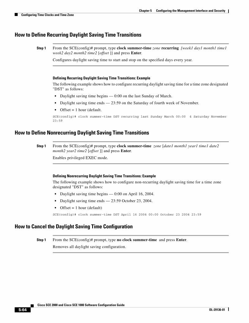
Chapter 5 Configuring the Management Interface and SecurityConfiguring Time Clocks and Time Zone
How to Define Recurring Daylight Saving Time Transitions
Step 1 From the SCE(config)# prompt, type clock summer-time zone recurring [week1 day1 month1 time1 week2 day2 month2 time2 [offset ]] and press Enter.
Configures daylight saving time to start and stop on the specified days every year.
Defining Recurring Daylight Saving Time Transitions: Example
The following example shows how to configure recurring daylight saving time for a time zone designated "DST" as follows:
• Daylight saving time begins — 0:00 on the last Sunday of March.
• Daylight saving time ends — 23:59 on the Saturday of fourth week of November.
• Offset = 1 hour (default.
SCE(config)# clock summer-time DST recurring last Sunday March 00:00 4 Saturday November 23:59
How to Define Nonrecurring Daylight Saving Time Transitions
Step 1 From the SCE(config)# prompt, type clock summer-time zone [date1 month1 year1 time1 date2 month2 year2 time2 [offset ]] and press Enter.
Enables privileged EXEC mode.
Defining Nonrecurring Daylight Saving Time Transitions: Example
The following example shows how to configure non-recurring daylight saving time for a time zone designated "DST" as follows:
• Daylight saving time begins — 0:00 on April 16, 2004.
• Daylight saving time ends — 23:59 October 23, 2004.
• Offset = 1 hour (default)
SCE(config)# clock summer-time DST April 16 2004 00:00 October 23 2004 23:59
How to Cancel the Daylight Saving Time Configuration
Step 1 From the SCE(config)# prompt, type no clock summer-time and press Enter.
Removes all daylight saving configuration.
5-64Cisco SCE 2000 and Cisco SCE 1000 Software Configuration Guide
OL-29136-01

Chapter 5 Configuring the Management Interface and SecurityConfiguring Time Clocks and Time Zone
How to Display the Current Daylight Saving Time Configuration
Step 1 From the SCE# prompt, type show timezone and press Enter.
Displays the current time zone and daylight saving time configuration.
5-65Cisco SCE 2000 and Cisco SCE 1000 Software Configuration Guide
OL-29136-01

Chapter 5 Configuring the Management Interface and SecurityConfiguring SNTP
Configuring SNTP The Simple Network Timing Protocol (SNTP) is a simple solution to the problem of synchronizing the clocks in the various elements of the network. SNTP provides access to a time source via the network. The system clock and calendar are then set in accordance with this external source.
• How to Enable the SNTP Multicast Client, page 5-66
• How to Disable the SNTP Multicast Client, page 5-66
• How to Enable the SNTP Unicast Client, page 5-67
• How to Disable the SNTP Unicast Client, page 5-67
• How to Define the SNTP Unicast Update Interval, page 5-68
• How to Display SNTP Information, page 5-68
There are two options for the SNTP client. These functions are independent, and the system employ either one or both.
• Multicast SNTP client — Listens to SNTP broadcasts and updates the system clock accordingly.
• Unicast SNTP client — Sends a periodic request to a configured SNTP server, and updates the system clock according to the server response.
Note It is recommended that an IP access control list be configured to prevent access from unauthorized SNTP or NTP multicast servers (see Configuring Access Control Lists (ACLs), page 5-27).
The following commands are relevant to SNTP configuration:
• [no] sntp broadcast client
• [no] sntp server address
• no sntp server all
• sntp update-interval
• show sntp
How to Enable the SNTP Multicast Client
Step 1 From the SCE(config)# prompt, type sntp broadcast client and press Enter.
Enables the SNTP multicast client. It will accept time updates from any broadcast server.
How to Disable the SNTP Multicast Client
Step 1 From the SCE(config)# prompt, type no sntp broadcast client and press Enter.
Disables the SNTP multicast client. It will not accept any broadcast time updates.
5-66Cisco SCE 2000 and Cisco SCE 1000 Software Configuration Guide
OL-29136-01
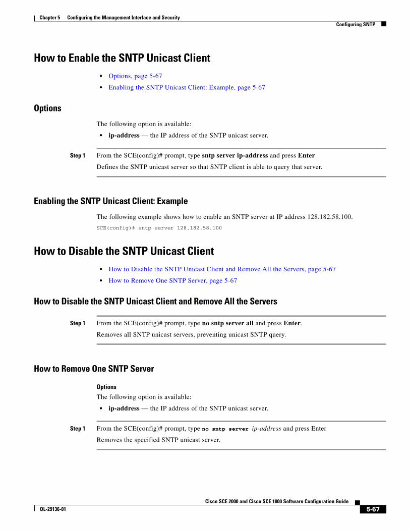
Chapter 5 Configuring the Management Interface and SecurityConfiguring SNTP
How to Enable the SNTP Unicast Client • Options, page 5-67
• Enabling the SNTP Unicast Client: Example, page 5-67
Options
The following option is available:
• ip-address — the IP address of the SNTP unicast server.
Step 1 From the SCE(config)# prompt, type sntp server ip-address and press Enter
Defines the SNTP unicast server so that SNTP client is able to query that server.
Enabling the SNTP Unicast Client: Example
The following example shows how to enable an SNTP server at IP address 128.182.58.100.
SCE(config)# sntp server 128.182.58.100
How to Disable the SNTP Unicast Client • How to Disable the SNTP Unicast Client and Remove All the Servers, page 5-67
• How to Remove One SNTP Server, page 5-67
How to Disable the SNTP Unicast Client and Remove All the Servers
Step 1 From the SCE(config)# prompt, type no sntp server all and press Enter.
Removes all SNTP unicast servers, preventing unicast SNTP query.
How to Remove One SNTP Server
Options
The following option is available:
• ip-address — the IP address of the SNTP unicast server.
Step 1 From the SCE(config)# prompt, type no sntp server ip-address and press Enter
Removes the specified SNTP unicast server.
5-67Cisco SCE 2000 and Cisco SCE 1000 Software Configuration Guide
OL-29136-01
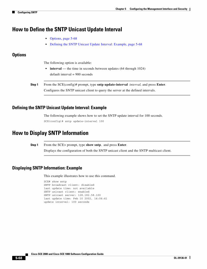
Chapter 5 Configuring the Management Interface and SecurityConfiguring SNTP
How to Define the SNTP Unicast Update Interval • Options, page 5-68
• Defining the SNTP Unicast Update Interval: Example, page 5-68
Options
The following option is available:
• interval — the time in seconds between updates (64 through 1024)
default interval = 900 seconds
Step 1 From the SCE(config)# prompt, type sntp update-interval interval, and press Enter.
Configures the SNTP unicast client to query the server at the defined intervals.
Defining the SNTP Unicast Update Interval: Example
The following example shows how to set the SNTP update interval for 100 seconds.
SCE(config)# sntp update-interval 100
How to Display SNTP Information
Step 1 From the SCE> prompt, type show sntp, and press Enter.
Displays the configuration of both the SNTP unicast client and the SNTP multicast client.
Displaying SNTP Information: Example
This example illustrates how to use this command.
SCE# show sntpSNTP broadcast client: disabledlast update time: not availableSNTP unicast client: enabledSNTP unicast server: 128.182.58.100last update time: Feb 10 2002, 14:06:41update interval: 100 seconds
5-68Cisco SCE 2000 and Cisco SCE 1000 Software Configuration Guide
OL-29136-01
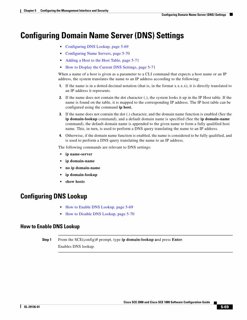
Chapter 5 Configuring the Management Interface and SecurityConfiguring Domain Name Server (DNS) Settings
Configuring Domain Name Server (DNS) Settings • Configuring DNS Lookup, page 5-69
• Configuring Name Servers, page 5-70
• Adding a Host to the Host Table, page 5-71
• How to Display the Current DNS Settings, page 5-71
When a name of a host is given as a parameter to a CLI command that expects a host name or an IP address, the system translates the name to an IP address according to the following:
1. If the name is in a dotted decimal notation (that is, in the format x.x.x.x), it is directly translated to an IP address it represents.
2. If the name does not contain the dot character (.), the system looks it up in the IP Host table. If the name is found on the table, it is mapped to the corresponding IP address. The IP host table can be configured using the command ip host.
3. If the name does not contain the dot (.) character, and the domain name function is enabled (See the ip domain-lookup command), and a default domain name is specified (See the ip domain-name command), the default domain name is appended to the given name to form a fully qualified host name. This, in turn, is used to perform a DNS query translating the name to an IP address.
4. Otherwise, if the domain name function is enabled, the name is considered to be fully qualified, and is used to perform a DNS query translating the name to an IP address.
The following commands are relevant to DNS settings:
• ip name-server
• ip domain-name
• no ip domain-name
• ip domain-lookup
• show hosts
Configuring DNS Lookup• How to Enable DNS Lookup, page 5-69
• How to Disable DNS Lookup, page 5-70
How to Enable DNS Lookup
Step 1 From the SCE(config)# prompt, type ip domain-lookup and press Enter.
Enables DNS lookup.
5-69Cisco SCE 2000 and Cisco SCE 1000 Software Configuration Guide
OL-29136-01
Chapter 5 Configuring the Management Interface and SecurityConfiguring Domain Name Server (DNS) Settings
How to Disable DNS Lookup
Step 1 From the SCE(config)# prompt, type no ip domain-lookup and press Enter.
Configuring Name Servers• Options, page 5-70
• How to Define Domain Name Servers, page 5-70
• How to Remove a Domain Name Server, page 5-70
• How to Remove All the Domain Name Servers, page 5-71
Options
The following options are available:
• server-ip-address — The IP address of the domain name server. You can define more than one DNS server (server-ip-address1, server-ip-address2, server-ip-address3)
How to Define Domain Name Servers
Use this command to specify the address of one or more name servers to use for name and address resolution.
Step 1 From the SCE(config)# prompt, type ip name-server server-address1 [server-address2 [server-address3]] and press Enter.
Defines the servers at the specified addresses as domain name servers.
Defining Domain Name Servers: Example
The following example shows how to configure the two name server (DNS) IP addresses.
SCE(config)#ip name-server 10.1.1.60 10.1.1.61
How to Remove a Domain Name Server
Step 1 From the SCE(config)# prompt, type no ip name-server server-address1 [server-address2 [server-address3], and press Enter.
Removes the specified server from the DNS list.
Removing a Domain Name Server: Example
The following example shows how to remove name server (DNS) IP addresses.
SCE(config)#no ip name-server 10.1.1.60 10.1.1.61
5-70Cisco SCE 2000 and Cisco SCE 1000 Software Configuration Guide
OL-29136-01
Chapter 5 Configuring the Management Interface and SecurityConfiguring Domain Name Server (DNS) Settings
How to Remove All the Domain Name Servers
Step 1 From the SCE(config)# prompt, type no ip name-server and press Enter.
Removes all configured DNS servers.
Adding a Host to the Host Table • Options, page 5-71
• Adding a Host and Removing a Host from the Host Table: Examples, page 5-71
Options
The following options are available:
• hostname — The name of the host.
• ip-address — The IP address of the host
Step 1 From the SCE(config)# prompt, type ip host hostname ip-address and press Enter.
Adds the specified host to the host table.
Adding a Host and Removing a Host from the Host Table: Examples
The following example shows how to add a host to the host table.
SCE(config)#ip host PC85 10.1.1.61
The following example shows how to remove a hostname together with all its IP mappings.
SCE(config)#no ip host PC85
How to Display the Current DNS Settings
Step 1 From the SCE# prompt, type show hosts and press Enter.
Displays current DNS settings.
5-71Cisco SCE 2000 and Cisco SCE 1000 Software Configuration Guide
OL-29136-01

Chapter 5 Configuring the Management Interface and SecurityConfiguring Domain Name Server (DNS) Settings
Displaying the Current DNS Settings: Example
The following example shows how to display current DNS information.
SCE# show hosts
Default domain is Cisco.com Name/address lookup uses domain serviceName servers are 10.1.1.60, 10.1.1.61Host Address---- -------PC85 10.1.1.61sce#
5-72Cisco SCE 2000 and Cisco SCE 1000 Software Configuration Guide
OL-29136-01

Chapter 5 Configuring the Management Interface and SecurityConfiguring the Management Port Physical Parameters
Configuring the Management Port Physical Parameters This interface has a transmission rate of 10 or 100 Mbps and is used for management operations and for transmitting RDRs, which are the output of traffic analysis and management operations.
The procedures for configuring this interface are explained in the following sections.
• Configuring the Management Interface Speed and Duplex Parameters, page 5-73
• Monitoring the Management Interface, page 5-74
Configuring the Management Interface Speed and Duplex Parameters This section presents sample procedures that describe how to configure the speed and the duplex of the Management Interface.
Both these parameters must be configured separately for each port.
• How to Configure the Duplex Operation of the Management Interface, page 5-73
• How to Configure the Speed of the Management Interface, page 5-74
How to Configure the Duplex Operation of the Management Interface
• Options, page 5-73
• Configuring the Duplex Operation of the Management Interface: Example, page 5-73
Options
The following options are available:
• duplex — duplex operation of the currently selected management port (0/1 or 0/2):
– full
– half
– auto (default) — auto-negotiation (do not force duplex on the link)
If the speed parameter is configured to auto, changing the duplex parameter has no effect (see ).
Step 1 From the SCE(config if)# prompt, type duplex auto|full|half and press Enter.
Configures the duplex operation of the currently selected management interface.
Configuring the Duplex Operation of the Management Interface: Example
The following example shows how to use this command to configure both management ports to half duplex mode.
SCE#configSCE(config)#interface mng 0/1SCE(config if)#duplex halfSCE(config if)#exitSCE(config)#interface mng 0/2SCE(config if)#duplex half
5-73Cisco SCE 2000 and Cisco SCE 1000 Software Configuration Guide
OL-29136-01

Chapter 5 Configuring the Management Interface and SecurityConfiguring the Management Port Physical Parameters
How to Configure the Speed of the Management Interface
• Options, page 5-74
• Configuring the Speed of the Management Interface: Example, page 5-74
Options
The following options are available:
• speed — speed in Mbps of the currently selected management port (0/1 or 0/2):
– 10
– 100
– auto (default) — auto-negotiation (do not force speed on the link)
If the duplex parameter is configured to auto, changing the speed parameter has no effect (see ).
Step 1 From the SCE(config if)# prompt, type speed 10|100|auto and press Enter.
Configures the speed of the currently selected management interface.
Configuring the Speed of the Management Interface: Example
The following example shows how to use this command to configure both management ports to The following example shows how to use this command to configure both management ports to half duplex mode.
SCE#configSCE(config)#interface mng 0/1SCE(config if)#speed 100SCE(config if)#exitSCE(config)#interface mng 0/2SCE(config if)#speed 100
Monitoring the Management Interface Use this command to display the following information for the specified management interface. Speed and duplex parameters are specific to the selected interface (port), while other parameters apply to both ports and are displayed by a command to either interface.
• speed
• duplex
• IP address
• active port
5-74Cisco SCE 2000 and Cisco SCE 1000 Software Configuration Guide
OL-29136-01

Chapter 5 Configuring the Management Interface and SecurityConfiguring the Management Port Physical Parameters
Step 1 From the SCE# prompt, type show interface Mng {01 | 0/2} [auto-fail-over|duplex|ip address|speed] and press Enter.
Displays the specified management interface configuration.
• If no option is specified, all management interface information is displayed.
• The displayed speed and duplex mode are for the management interface specified in the command.
5-75Cisco SCE 2000 and Cisco SCE 1000 Software Configuration Guide
OL-29136-01

Chapter 5 Configuring the Management Interface and SecurityConfiguring the Management Port Physical Parameters
5-76Cisco SCE 2000 and Cisco SCE 1000 Software Configuration Guide
OL-29136-01