man b&w stationary engines alternative fuels
TRANSCRIPT
MAN B&W Stationary EnginesAlternative Fuels

Contents
Abstract .......................................................................................................5
Business concept .........................................................................................5
Definition of alternative fuels..........................................................................5
Experience with alternative fuels....................................................................6
Fuel supply system .......................................................................................8
Other auxiliary systems .................................................................................8
Selection of cylinder lube oil ..........................................................................8
Emission control ...........................................................................................9
Status in 2015..............................................................................................9
Evaluation of alternative fuels ...................................................................... 10
Outlook ...................................................................................................... 10
MAN B&W Stationary Engines – Alternative Fuels 3

MAN B&W Stationary Engines – Alternative Fuels 5
MAN B&W Stationary EnginesAlternative Fuels
Abstract
The demand for energy and technologi-
cal development is increasing world-
wide.
Ideas, proven by operational experi-
ence on reciprocating engines with the
highest possible efficiency level, are
subject to renewed interest.
This paper deals with the use of alter-
native fuels in MAN B&W two-stroke
low speed engines for stationary ap-
plication.
Business concept
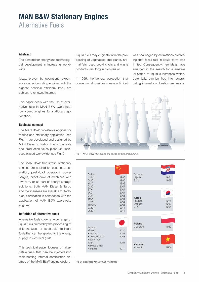
The MAN B&W two-stroke engines for
marine and stationary application, see
Fig. 1, are developed and designed by
MAN Diesel & Turbo. The actual sale
and production takes place via licen-
sees placed worldwide, see Fig. 2.
The MAN B&W two-stroke stationary
engines are applied for base-load op-
eration, peak-load operation, power
barges, direct drive of machines with
low rpm, or as part of energy storage
solutions. Both MAN Diesel & Turbo
and the licensees are available for tech-
nical clarification in connection with the
application of MAN B&W two-stroke
engines.
Definition of alternative fuels
Alternative fuels cover a wide range of
liquid fuels created by the processing of
different types of feedstock into liquid
fuels that can be applied to the energy
supply to electrical grids.
This technical paper focuses on alter-
native fuels that can be injected into
reciprocating internal combustion en-
gines of the MAN B&W engine design.
Liquid fuels may originate from the pro-
cessing of vegetables and plants, ani-
mal fats, used cooking oils and waste
products, resulting in pyrolysis oil.
In 1995, the general perception that
conventional fossil fuels were unlimited
was challenged by estimations predict-
ing that fossil fuel in liquid form was
limited. Consequently, new ideas have
emerged in the search for alternative
utilisation of liquid substances which,
potentially, can be fired into recipro-
cating internal combustion engines to
3,605 kW 79,520 kW
Fig. 1: MAN B&W two-stroke low speed engine programme
Fig. 2: Licensees for MAN B&W engines
CroatiaUljanik 1954Split 1967
KoreaHyundai 1976Doosan 1983STX 1984
ChinaHHM 1980DMD 1980YMD 1989CMD 2007STX 2007JAD 2007CMP 2008ZHD 2008RPM 2008YungPu 2008GMD 2011QMD 2014
PolandCegielski 1959Japan
Mitsui 1926 Makita 1981 Diesel United 2008Hitachi incl. IMEX 1951Kawasaki incl. Hanshin 1911
VietnamVinashin 2004
MAN B&W Stationary Engines – Alternative Fuels6
provide the highest possible efficiency
and secure the power supply in a world
with scarce resources. This is why we
choose to apply the designation alter-
native fuels.
Alternative fuels from vegetables cover
crude rapeseed oil, crude sunflower oil
and crude soya oil.
Alternative fuels from plants cover
crude palm oil and crude jatropha oil.
Alternative fuels with the designation
animal fats covers fats produced by the
processing of any type of meat in the
meat processing industry.
Alternative fuels with the designation
used cooking oil covers both vegetable
and animal-based products that have
already been applied in cooking pro-
cesses either in private homes or, more
likely, at restaurants.
Alternative fuels with the designation
“pyrolysis oil” are derived from the pro-
cessing of waste products according
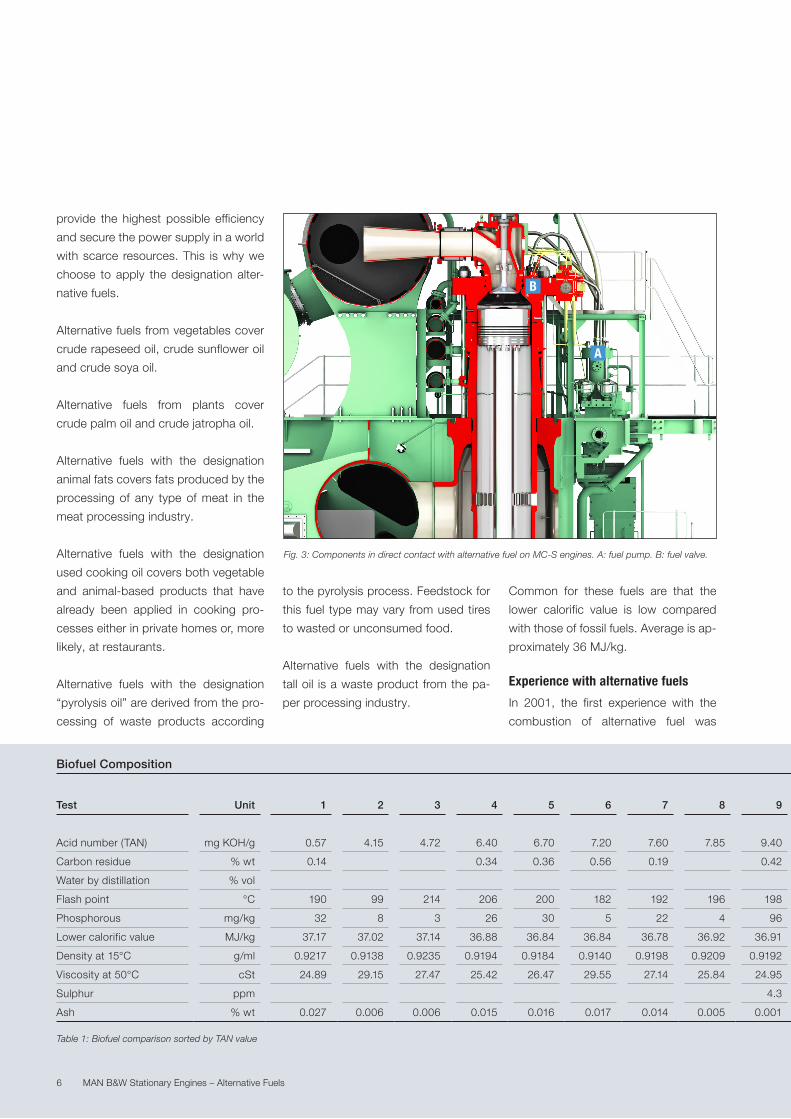
Fig. 3: Components in direct contact with alternative fuel on MC-S engines. A: fuel pump. B: fuel valve.
to the pyrolysis process. Feedstock for
this fuel type may vary from used tires
to wasted or unconsumed food.
Alternative fuels with the designation
tall oil is a waste product from the pa-
per processing industry.
Common for these fuels are that the
lower calorific value is low compared
with those of fossil fuels. Average is ap-
proximately 36 MJ/kg.
Experience with alternative fuels
In 2001, the first experience with the
combustion of alternative fuel was
A
B
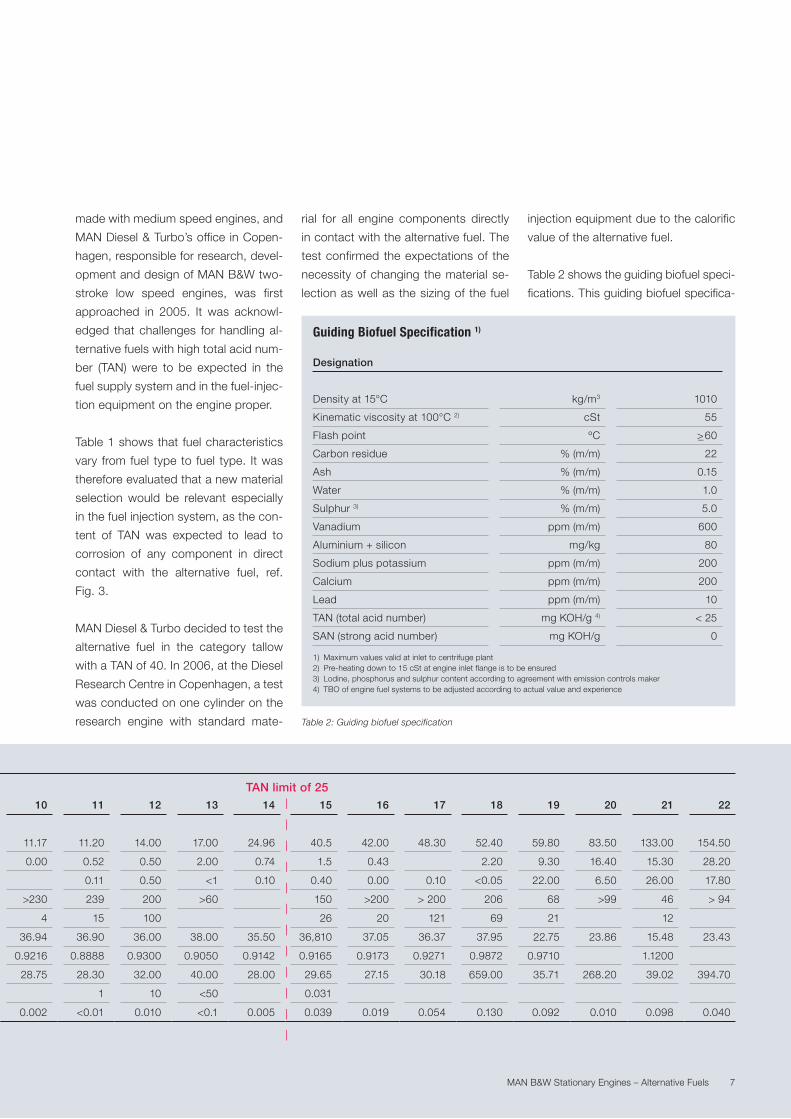
Table 1: Biofuel comparison sorted by TAN value
Biofuel Composition
Test Unit 1 2 3 4 5 6 7 8 9 10 11 12 13 14 15 16 17 18 19 20 21 22
Acid number (TAN) mg KOH/g 0.57 4.15 4.72 6.40 6.70 7.20 7.60 7.85 9.40 11.17 11.20 14.00 17.00 24.96 40.5 42.00 48.30 52.40 59.80 83.50 133.00 154.50
Carbon residue % wt 0.14 0.34 0.36 0.56 0.19 0.42 0.00 0.52 0.50 2.00 0.74 1.5 0.43 2.20 9.30 16.40 15.30 28.20
Water by distillation % vol 0.11 0.50 <1 0.10 0.40 0.00 0.10 <0.05 22.00 6.50 26.00 17.80
Flash point °C 190 99 214 206 200 182 192 196 198 >230 239 200 >60 150 >200 > 200 206 68 >99 46 > 94
Phosphorous mg/kg 32 8 3 26 30 5 22 4 96 4 15 100 26 20 121 69 21 12
Lower calorific value MJ/kg 37.17 37.02 37.14 36.88 36.84 36.84 36.78 36.92 36.91 36.94 36.90 36.00 38.00 35.50 36,810 37.05 36.37 37.95 22.75 23.86 15.48 23.43
Density at 15°C g/ml 0.9217 0.9138 0.9235 0.9194 0.9184 0.9140 0.9198 0.9209 0.9192 0.9216 0.8888 0.9300 0.9050 0.9142 0.9165 0.9173 0.9271 0.9872 0.9710 1.1200
Viscosity at 50°C cSt 24.89 29.15 27.47 25.42 26.47 29.55 27.14 25.84 24.95 28.75 28.30 32.00 40.00 28.00 29.65 27.15 30.18 659.00 35.71 268.20 39.02 394.70
Sulphur ppm 4.3 1 10 <50 0.031
Ash % wt 0.027 0.006 0.006 0.015 0.016 0.017 0.014 0.005 0.001 0.002 <0.01 0.010 <0.1 0.005 0.039 0.019 0.054 0.130 0.092 0.010 0.098 0.040
MAN B&W Stationary Engines – Alternative Fuels 7
Guiding Biofuel Specification 1)
Designation
Density at 15°C kg/m3 1010
Kinematic viscosity at 100°C 2) cSt 55
Flash point ºC >_ 60
Carbon residue % (m/m) 22
Ash % (m/m) 0.15
Water % (m/m) 1.0
Sulphur 3) % (m/m) 5.0
Vanadium ppm (m/m) 600
Aluminium + silicon mg/kg 80
Sodium plus potassium ppm (m/m) 200
Calcium ppm (m/m) 200
Lead ppm (m/m) 10
TAN (total acid number) mg KOH/g 4) < 25
SAN (strong acid number) mg KOH/g 0
1) Maximum values valid at inlet to centrifuge plant2) Pre-heating down to 15 cSt at engine inlet flange is to be ensured3) Lodine, phosphorus and sulphur content according to agreement with emission controls maker4) TBO of engine fuel systems to be adjusted according to actual value and experience
made with medium speed engines, and
MAN Diesel & Turbo’s office in Copen-
hagen, responsible for research, devel-
opment and design of MAN B&W two-
stroke low speed engines, was first
approached in 2005. It was acknowl-
edged that challenges for handling al-
ternative fuels with high total acid num-
ber (TAN) were to be expected in the
fuel supply system and in the fuel-injec-
tion equipment on the engine proper.
Table 1 shows that fuel characteristics
vary from fuel type to fuel type. It was
therefore evaluated that a new material
selection would be relevant especially
in the fuel injection system, as the con-
tent of TAN was expected to lead to
corrosion of any component in direct
contact with the alternative fuel, ref.
Fig. 3.
MAN Diesel & Turbo decided to test the
alternative fuel in the category tallow
with a TAN of 40. In 2006, at the Diesel
Research Centre in Copenhagen, a test
was conducted on one cylinder on the
research engine with standard mate-
rial for all engine components directly
in contact with the alternative fuel. The
test confirmed the expectations of the
necessity of changing the material se-
lection as well as the sizing of the fuel
injection equipment due to the calorific
value of the alternative fuel.
Table 2 shows the guiding biofuel speci-
fications. This guiding biofuel specifica-
Biofuel Composition
Test Unit 1 2 3 4 5 6 7 8 9 10 11 12 13 14 15 16 17 18 19 20 21 22
Acid number (TAN) mg KOH/g 0.57 4.15 4.72 6.40 6.70 7.20 7.60 7.85 9.40 11.17 11.20 14.00 17.00 24.96 40.5 42.00 48.30 52.40 59.80 83.50 133.00 154.50
Carbon residue % wt 0.14 0.34 0.36 0.56 0.19 0.42 0.00 0.52 0.50 2.00 0.74 1.5 0.43 2.20 9.30 16.40 15.30 28.20
Water by distillation % vol 0.11 0.50 <1 0.10 0.40 0.00 0.10 <0.05 22.00 6.50 26.00 17.80
Flash point °C 190 99 214 206 200 182 192 196 198 >230 239 200 >60 150 >200 > 200 206 68 >99 46 > 94
Phosphorous mg/kg 32 8 3 26 30 5 22 4 96 4 15 100 26 20 121 69 21 12
Lower calorific value MJ/kg 37.17 37.02 37.14 36.88 36.84 36.84 36.78 36.92 36.91 36.94 36.90 36.00 38.00 35.50 36,810 37.05 36.37 37.95 22.75 23.86 15.48 23.43
Density at 15°C g/ml 0.9217 0.9138 0.9235 0.9194 0.9184 0.9140 0.9198 0.9209 0.9192 0.9216 0.8888 0.9300 0.9050 0.9142 0.9165 0.9173 0.9271 0.9872 0.9710 1.1200
Viscosity at 50°C cSt 24.89 29.15 27.47 25.42 26.47 29.55 27.14 25.84 24.95 28.75 28.30 32.00 40.00 28.00 29.65 27.15 30.18 659.00 35.71 268.20 39.02 394.70
Sulphur ppm 4.3 1 10 <50 0.031
Ash % wt 0.027 0.006 0.006 0.015 0.016 0.017 0.014 0.005 0.001 0.002 <0.01 0.010 <0.1 0.005 0.039 0.019 0.054 0.130 0.092 0.010 0.098 0.040
Table 2: Guiding biofuel specification
TAN limit of 25
MAN B&W Stationary Engines – Alternative Fuels8
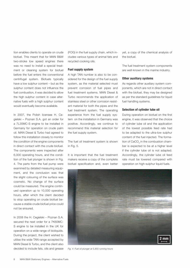
Fig. 4: Fuel oil plunger at 5,855 running hours
tion enables clients to operate on crude
biofuel. This meant that for MAN B&W
two-stroke low speed engines there
was no need to install a special treat-
ment or cleaning system for biofuel
before the fuel enters the conventional
centrifugal system. Biofuels typically
have a low sulphur content – but as the
sulphur content does not influence the
fuel combustion, it was decided to allow
the high sulphur content in case alter-
native fuels with a high sulphur content
would eventually become available.
In 2007, the Polish licensee H. Ce-
gielski – Poznan S.A. got an order for
a 7L35MC-S engine to be installed in
Germany for operation on crude palm
oil. MAN Diesel & Turbo had agreed to
follow this installation closely to monitor
the condition of the engine components
in direct contact with the crude biofuel.
The components were inspected after
6,000 operating hours, and the condi-
tion of the fuel plunger is shown in Fig.
4. The parts from the fuel pump were
examined by detailed measuring equip-
ment, and the conclusion was that
the slight colouring of the surface was
cosmetic. No change of the surface
could be measured. The engine contin-
ued operation up to 10,000 operating
hours, after which the client decided
to stop operating on crude biofuel be-
cause a stable crude biofuel price could
not be ensured.
In 2008 the H. Cegielski – Poznan S.A.
secured the next order for a 7K60MC-
S engine to be installed in the UK for
operation on a wide range of bioliquids.
During the project, the client wished to
utilise the wide TAN range accepted by
MAN Diesel & Turbo, and the client also
decided to include fats, oils and grease
(FOG) in the fuel supply chain, which in-
cludes various types of animal fats and
recycled cooking oils.
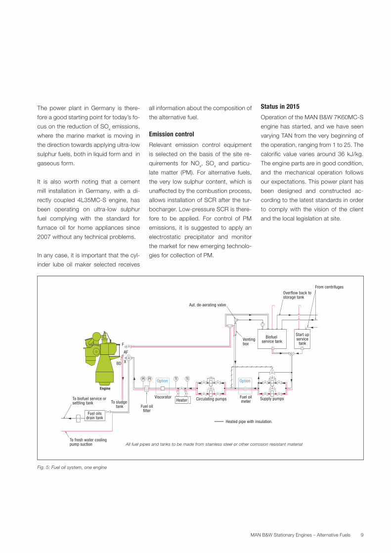
Fuel supply system
A high TAN number is also to be con-
sidered for the design of the fuel supply
system, as the material selected must
prevent corrosion of fuel pipes and
fuel treatment systems. MAN Diesel &
Turbo recommends the application of
stainless steel or other corrosion resist-
ant material for both the pipes and the
fuel treatment system. The operating
experience from the fuel supply sys-
tem on the installation in Germany was
positive. Accordingly, we continue to
recommend this material selection for
the fuel supply system.
The fuel oil treatment system is shown
in Fig. 5.
It is important that the fuel treatment
makers receive a copy of the complete
biofuel specification and, even better
yet, a copy of the chemical analysis of
the biofuel.
The fuel treatment system components
are well-known in the marine industry.
Other auxiliary systems
As regards other auxiliary system com-
ponents, which are not in direct contact
with the biofuel, they may be designed
as per the standard guidelines for liquid
fuel handling systems.
Selection of cylinder lube oil
During operation on biofuel on the first
engine, it was observed that the choice
of cylinder lube oil and the application
of the lowest possible feed rate had
to be adapted to the ultra-low sulphur
content of the fuel injected. The forma-
tion of CaCO3 in the combustion cham-
ber is expected to be at a higher level
if the cylinder lube oil is not adapted.
Accordingly, the cylinder lube oil feed
rate must be lowered compared with
operation on high-sulphur liquid fuels.
2 mm
MAN B&W Stationary Engines – Alternative Fuels 9
The power plant in Germany is there-
fore a good starting point for today’s fo-
cus on the reduction of SOx emissions,
where the marine market is moving in
the direction towards applying ultra-low
sulphur fuels, both in liquid form and in
gaseous form.
It is also worth noting that a cement
mill installation in Germany, with a di-
rectly coupled 4L35MC-S engine, has
been operating on ultra-low sulphur
fuel complying with the standard for
furnace oil for home appliances since
2007 without any technical problems.
In any case, it is important that the cyl-
inder lube oil maker selected receives
all information about the composition of
the alternative fuel.
Emission control
Relevant emission control equipment
is selected on the basis of the site re-
quirements for NOx, SOx and particu-
late matter (PM). For alternative fuels,
the very low sulphur content, which is
unaffected by the combustion process,
allows installation of SCR after the tur-
bocharger. Low-pressure SCR is there-
fore to be applied. For control of PM
emissions, it is suggested to apply an
electrostatic precipitator and monitor
the market for new emerging technolo-
gies for collection of PM.
Status in 2015
Operation of the MAN B&W 7K60MC-S
engine has started, and we have seen
varying TAN from the very beginning of
the operation, ranging from 1 to 25. The
calorific value varies around 36 kJ/kg.
The engine parts are in good condition,
and the mechanical operation follows
our expectations. This power plant has
been designed and constructed ac-
cording to the latest standards in order
to comply with the vision of the client
and the local legislation at site.
Heated pipe with insulation.
F
X
Heater
Option OptionTITIPIPI
Overflow back to storage tank
AF
Fuel oilsdrain tank
BD
To sludge tank Fuel oil
filter
Fuel oilmeter
Viscorator Circulating pumps
Start upservice
tank
Supply pumps
Aut. de-aerating valve
From centrifuges
Ventingbox
Biofuel service tank
To fresh water coolingpump suction
To biofuel service or settling tank
All fuel pipes and tanks to be made from stainless steel or other corrosion resistant material
Engine
Fig. 5: Fuel oil system, one engine
MAN B&W Stationary Engines – Alternative Fuels10
Evaluation of alternative fuels
MAN Diesel & Turbo always welcomes
questions about application of alter-
native fuels, and each request is ad-
dressed systematically step-by-step as
outlined in the following:
1. Clarification about the feedstock ap-
plied.
2. Explanation of the production pro-
cess.
3. The amount of the alternative fuel
available in the world market.
4. Expected fuel price when large scale
production is in place.
Items 1-4 provide information and a ba-
sic understanding. It is acknowledged
that what is at the initial stage today
may give new prospects tomorrow –
but it is always good to have a strategy
that is shared by all related parties.
5. One-litre sample (minimum) to be
sent to MAN Diesel & Turbo for
chemical analysis.
6. One-litre sample (minimum) to be
sent to MAN Diesel & Turbo for sta-
bility analysis.
7. Pump rig test without combustion at
the Diesel Research Centre in Co-
penhagen.
8. Combustion test for minimum 20
hours on one cylinder at the Diesel
Research Centre in Copenhagen.
9. Service test for minimum 4,000
hours.
The basic understanding of items 7-9 is
that the each step is commenced when
MAN Diesel & Turbo sees a possibility
of realising a positive outcome and, of
course, the steps 5-9 are subject to a
non-exclusive commercial and confi-
dential agreement.
With a positive outcome of step 9, it will
be possible for MAN Diesel & Turbo to
issue a no objection letter for the alter-
native fuel with a given specification.
Changes of the alternative fuel compo-
sition is to be reviewed and commented
by MAN Diesel & Turbo in each case, as
some of the steps may have to be re-
peated in order to clarify expected chal-
lenges relevant for the engine design.
Outlook
Fuel flexibility is important for MAN Diesel & Turbo as this can contribute posi-
tively to the diversity in the energy supply together with the unrivalled efficiency
of the MAN B&W two-stroke engine in a single cycle. Clients deserve the right
to select new possibilities that may become available as a result of the con-
stant technological development in any technical field. There is a first time for
everything, and we are ready to explore the combustion of alternative fuels in
reciprocating internal combustion engines of our design already at the early
stage of production.

Reference
Stationary MAN B&W MC-S Engine
For Biofuel Applications
5510-0098-00ppr
MAN Diesel & Turbo, Copenhagen,
Denmark, September 2010

MAN Diesel & TurboTeglholmsgade 412450 Copenhagen SV, DenmarkPhone +45 33 85 11 00Fax +45 33 85 10 [email protected]
MAN Diesel & Turbo – a member of the MAN Group
All data provided in this document is non-binding. This data serves informational purposes only and is especially not guaranteed in any way. Depending on the subsequent specific individual projects, the relevant data may be subject to changes and will be assessed and determined individually for each project. This will depend on the particular characteristics of each individual project, especially specific site and operational conditions. Copyright © MAN Diesel & Turbo. 5510-0177-00ppr Nov 2015 Printed in Denmark