making modern living possible - 4006119988.com lhd manual.pdf · 7.5.4 text blocks 132 7.5.5...
TRANSCRIPT

MAKING MODERN LIVING POSSIBLE
VLT® Low Harmonic Drive for AAF006Operating Instructions
VLT® AutomationDrive

Contents
1 How to Read these Operating Instructions 4
1.1.1 Copyright, Limitation of Liability and Revision Rights 4
1.1.3 Approvals 4
2 Safety 6
2.1.2 General Warning 6
2.1.3 Before Commencing Repair Work 7
2.1.4 Special conditions 7
2.1.5 Avoid Unintended Start 7
2.1.6 Safe Stop Installation 7
2.1.7 Safe Stop of the Frequency Converter 9
2.1.8 IT Mains 10
3 Introduction to the Low Harmonic Drive 11
3.1.1 Working Principle 11
3.1.2 IEEE519 Compliance 11
3.1.3 Ordering Form Type Code 12
4 How to Install 13
4.1 How to Get Started 13
4.2 Pre-installation 13
4.2.1 Planning the Installation Site 13
4.2.2 Receiving the Frequency Converter 14
4.2.3 Transportation and Unpacking 14
4.2.4 Lifting 14
4.2.5 Mechanical Dimensions 16
4.3 Mechanical Installation 20
4.3.3 Terminal Locations - Frame Size D13 22
4.3.4 Terminal Locations - Frame Size E9 23
4.3.5 Terminal Locations - Frame Size F18 25
4.3.6 Cooling and Airflow 28
4.4 Field Installation of Options 32
4.4.1 Installation of Input Plate Options 32
4.4.2 Installation of Mains Shield for Frequency Converters 33
4.5 Frame Size F Panel Options 33
4.6 Electrical Installation 34
4.6.1 Power Connections 34
4.6.2 Earthing 43
4.6.4 RFI Switch 43
4.6.5 Torque 43
Contents VLT AutomationDrive LHD for AAF 006 Operating Instructions
MG37A102 - VLT® is a registered Danfoss trademark 1

4.6.6 Shielded Cables 44
4.6.10 Load Sharing 45
4.6.11 Mains Connection 45
4.6.12 External Fan Supply 46
4.6.13 Power and Control Wiring for Unscreened Cables 46
4.6.14 Fuses 46
4.6.20 Control Cable Routing 49
4.6.22 Electrical Installation, Control Terminals 50
4.7 Connection Examples for Control of Motor with External Signal Provider 51
4.7.1 Start/Stop 51
4.7.2 Pulse Start/Stop 51
4.8 Electrical Installation - Additional 53
4.8.1 Electrical Installation, Control Cables 53
4.8.2 Switches S201, S202, and S801 54
4.9 Final Set-up and Test 55
4.10 Additional Connections 56
4.10.1 Mechanical Brake Control 56
4.10.3 Motor Thermal Protection 57
5 How to Operate the Low Harmonic Drive 58
5.1.2 How to Operate Graphical LCP (GLCP) 58
6 How to Programme the Low Harmonic Drive 65
6.1 How to Programme the Frequency Converter 65
6.1.1 Quick Setup Parameters 65
6.1.2 Basic Setup Parameters 67
6.1.3.1 PTC Thermistor Connection 68
6.1.3.2 KTY Sensor Connection 69
6.1.3.3 ETR 69
6.1.3.4 ATEX ETR 70
6.1.3.5 Klixon 70
6.2 How to Programme the Active Filter 83
6.2.1 Using the Low Harmonic Drive in NPN Mode 84
6.3 Parameter Lists - Frequency Converter 85
6.4 Parameter Lists - Active Filter 119
6.4.1 Operation/Display 0-** 119
6.4.2 Digital In/Out 5-** 120
6.4.3 Comm. and Options 8-** 120
6.4.4 Special Functions 14-** 121
6.4.5 FC Information 15-** 122
6.4.6 Data Readouts 16-** 123
Contents VLT AutomationDrive LHD for AAF 006 Operating Instructions
2 MG37A102 - VLT® is a registered Danfoss trademark
6.4.7 AF Settings 300-** 124
6.4.8 AF Readouts 301-** 125
7 RS-485 Installation and Set-up 126
7.1.2 EMC Precautions 127
7.2 Network Configuration 127
7.2.1 Set-up 127
7.3 FC Protocol Message Framing Structure 127
7.3.1 Content of a Character (byte) 127
7.3.2 Telegram Structure 127
7.3.3 Telegram Length (LGE) 128
7.3.4 Frequency Converter Address (ADR) 128
7.3.5 Data Control Byte (BCC) 128
7.3.6 The Data Field 128
7.3.7 The PKE Field 129
7.3.8 Parameter Number (PNU) 130
7.3.9 Index (IND) 130
7.3.10 Parameter Value (PWE) 130
7.3.11 Data Types Supported by the Frequency Converter 130
7.3.12 Conversion 131
7.3.13 Process Words (PCD) 131
7.4 Examples 131
7.4.1 Writing a Parameter Value 131
7.4.2 Reading a Parameter Value 131
7.5 How to Access Parameters 132
7.5.1 Parameter Handling 132
7.5.2 Storage of Data 132
7.5.3 IND 132
7.5.4 Text Blocks 132
7.5.5 Conversion Factor 132
7.5.6 Parameter Values 132
8 General Specifications 133
8.2 Filter Specifications 140
9 Troubleshooting 141
9.1 Alarms and Warnings - Frequency Converter (Right LCP) 141
9.1.1 Warnings/Alarm Messages 141
9.2 Alarms and Warnings - Filter (Left LCP) 152
Index 158
Contents VLT AutomationDrive LHD for AAF 006 Operating Instructions
MG37A102 - VLT® is a registered Danfoss trademark 3

1 How to Read these Operating Instructions
1.1.1 Copyright, Limitation of Liability andRevision Rights
This publication contains information proprietary toDanfoss. By accepting and using this manual the useragrees that the information contained herein will be usedsolely for operating equipment from Danfoss or equipmentfrom other vendors provided that such equipment isintended for communication with Danfoss equipment overa serial communication link. This publication is protectedunder the Copyright laws of Denmark and most othercountries.
Danfoss does not warrant that a software programproduced according to the guidelines provided in thismanual will function properly in every physical, hardwareor software environment.
Although Danfoss has tested and reviewed the documen-tation within this manual, Danfoss makes no warranty orrepresentation, neither expressed nor implied, with respectto this documentation, including its quality, performance,or fitness for a particular purpose.
In no event shall Danfoss be liable for direct, indirect,special, incidental, or consequential damages arising out ofthe use, or the inability to use information contained inthis manual, even if advised of the possibility of suchdamages. In particular, Danfoss is not responsible for anycosts, including but not limited to those incurred as aresult of lost profits or revenue, loss or damage ofequipment, loss of computer programs, loss of data, thecosts to substitute these, or any claims by third parties.
Danfoss reserves the right to revise this publication at anytime and to make changes to its contents without priornotice or any obligation to notify former or present usersof such revisions or changes.
1.1.2 Available Literature for VLTAutomationDrive
- The VLT® AutomationDrive Operating Instructions -High Power, MG33UXYY provide the necessaryinformation for getting the frequency converterup and running.
- The VLT® AutomationDrive Design Guide MG33BXYYentails all technical information about thefrequency converter and customer design andapplications.
- The VLT® AutomationDrive Programming GuideMG33MXYY provides information on how toprogramme and includes complete parameterdescriptions.
- The VLT® AutomationDrive Profibus OperatingInstructions MG33CXYY provide the informationrequired for controlling, monitoring andprogramming the frequency converter via aProfibus fieldbus.
- The VLT® AutomationDrive DeviceNet OperatingInstructions MG33DXYY provide the informationrequired for controlling, monitoring andprogramming the frequency converter via aDeviceNet fieldbus.
X = Revision numberYY = Language code
Danfoss technical literature is also available online atwww.danfoss.com/drives.
VLT® AutomationDriveOperating InstructionsSoftware version: 6.5x
These Operating Instructions can be used for all VLT AutomationLow Harmonic Drive frequency converters with software version6.5x.The software version number can be seen from 15-43 SoftwareVersion.
Table 1.1
NOTEThe Low Harmonic Drive has two LCPs, one for thefrequency converter (to the right) and one for the activefilter (to the left). Each LCP controls only the unit it isconnected to and there is only a start/stop signal betweenthe two units.
1.1.3 Approvals
Table 1.2
How to Read these Operating... VLT AutomationDrive LHD for AAF 006 Operating Instructions
4 MG37A102 - VLT® is a registered Danfoss trademark
11
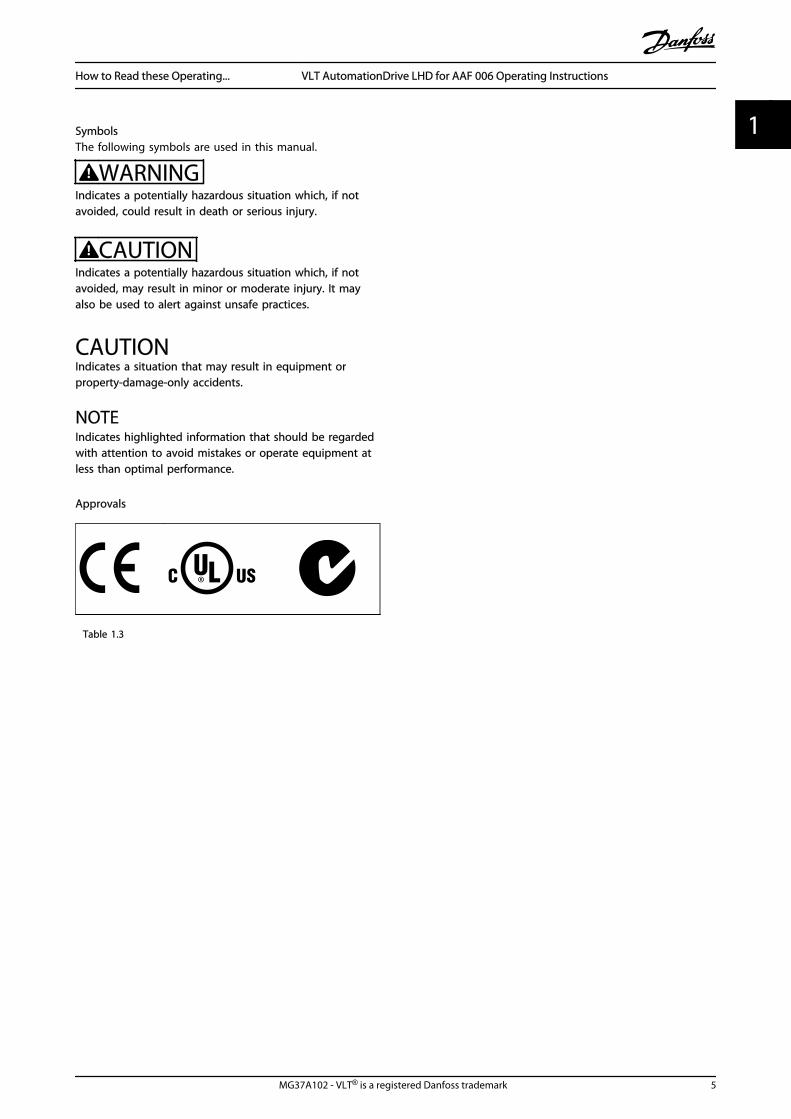
SymbolsThe following symbols are used in this manual.
WARNINGIndicates a potentially hazardous situation which, if notavoided, could result in death or serious injury.
CAUTIONIndicates a potentially hazardous situation which, if notavoided, may result in minor or moderate injury. It mayalso be used to alert against unsafe practices.
CAUTIONIndicates a situation that may result in equipment orproperty-damage-only accidents.
NOTEIndicates highlighted information that should be regardedwith attention to avoid mistakes or operate equipment atless than optimal performance.
Approvals
Table 1.3
How to Read these Operating... VLT AutomationDrive LHD for AAF 006 Operating Instructions
MG37A102 - VLT® is a registered Danfoss trademark 5
1 1

2 Safety
2.1.1 Safety Note
WARNINGThe voltage of the frequency converter is dangerouswhenever connected to mains. Incorrect installation of themotor, frequency converter or fieldbus may cause damageto the equipment, serious personal injury or death.Consequently, the instructions in this manual, as well asnational and local rules and safety regulations, must becomplied with.
Safety Regulations1. The frequency converter must be disconnected
from mains if repair work is to be carried out.Check that the mains supply has been discon-nected and that the necessary time has passedbefore removing motor and mains plugs.
2. The [Off/Reset] key on the LCP of the frequencyconverter does not disconnect the equipmentfrom mains and is thus not to be used as a safetyswitch.
3. Correct protective earthing of the equipmentmust be established, the user must be protectedagainst supply voltage, and the motor must beprotected against overload in accordance withapplicable national and local regulations.
4. The earth leakage currents are higher than 3.5mA.
5. Protection against motor overload is set by 1-90 Motor Thermal Protection. If this function isdesired, set 1-90 Motor Thermal Protection to datavalue [ETR trip] (default value) or data value [ETRwarning].
NOTEThe function is initialised at 1.16 x rated motor current andrated motor frequency. For the North American market:The ETR functions provide class 20 motor overloadprotection in accordance with NEC.
6. Note that the frequency converter has voltageinputs other than L1, L2 and L3, when loadsharing (linking of DC intermediate circuit) andexternal 24 V DC have been installed. Check thatall voltage inputs have been disconnected andthat the necessary time has passed beforecommencing repair work.
Installation at High Altitudes
WARNINGAt altitudes above 3 km, contact Danfoss regarding PELV
Warning against Unintended Start1. The motor can be brought to a stop by means of digitalcommands, bus commands, references or a local stop,while the frequency converter is connected to mains. Ifpersonal safety considerations make it necessary to ensurethat no unintended start occurs, these stop functions arenot sufficient.2. While parameters are being changed, the motor maystart. Consequently, the stop key [Reset] must always beactivated; following which data can be modified.3. A motor that has been stopped may start if faults occurin the electronics of the frequency converter, or if atemporary overload or a fault in the supply mains or themotor connection ceases.
WARNINGTouching the electrical parts may be fatal - even after theequipment has been disconnected from mains.
Also make sure that other voltage inputs have beendisconnected, such as external 24 V DC, load sharing(linkage of DC intermediate circuit), as well as the motorconnection for kinetic back up.
2.1.2 General Warning
WARNINGTouching the electrical parts may be fatal - even after theequipment has been disconnected from mains.Also make sure that other voltage inputs have beendisconnected, (linkage of DC intermediate circuit), as wellas the motor connection for kinetic back-up.Before touching any potentially live parts of the frequencyconverter, wait at least as follows:380-480 V, 132-200 kW, wait at least 20 minutes.380-480 V, 250-630 kW, wait at least 40 minutes.Shorter time is allowed only if indicated on the nameplatefor the specific unit. Be aware that there may be highvoltage on the DC links even when the Control Card LEDsare turned off. A red LED is mounted on a circuit boardinside both the frequency converter and the active filter toindicate the DC bus voltages. The red LED will stay lit untilthe DC link is 50 V DC or lower.
Safety VLT AutomationDrive LHD for AAF 006 Operating Instructions
6 MG37A102 - VLT® is a registered Danfoss trademark
22

WARNINGLeakage CurrentThe earth leakage current from the frequency converterexceeds 3.5 mA. According to IEC 61800-5-1 a reinforcedProtective Earth connection must be ensured by means of:a min. 10 mm² Cu or 16 mm² Al PE-wire or an addtional PEwire - with the same cable cross section as the Mainswiring - must be terminated separately.Residual Current DeviceThis product can cause a DC current in the protectiveconductor. Where a residual current device (RCD) is usedfor extra protection, only an RCD of Type B (time delayed)shall be used on the supply side of this product. See alsoRCD Application Note MN90GX02.Protective earthing of the frequency converter and the useof RCDs must always follow national and local regulations.
2.1.3 Before Commencing Repair Work
1. Disconnect the frequency converter from mains
2. Disconnect DC bus terminals 88 and 89
3. Wait at least the time mentioned in 2.1.2 GeneralWarning
2.1.4 Special conditions
Electrical ratings:The rating indicated on the nameplate of the frequencyconverter is based on a typical 3-phase mains powersupply, within the specified voltage, current andtemperature range, which is expected to be used in mostapplications.
The frequency converters also support other specialapplications, which affect the electrical ratings of thefrequency converter. Special conditions which affect theelectrical ratings might be:
• Single phase applications
• High temperature applications which requirederating of the electrical ratings
• Marine applications with more severe environ-mental conditions.
Consult the relevant clauses in these instructions and inthe Design Guide for information about the electricalratings.
Installation requirements:The overall electrical safety of the frequency converterrequires special installation considerations regarding:
• Fuses and circuit breakers for over-current andshort-circuit protection
• Selection of power cables (mains, motor, brake,loadsharing and relay)
• Grid configuration (IT,TN, grounded leg, etc.)
• Safety of low-voltage ports (PELV conditions).
Consult the relevant clauses in these instructions and inthe Design Guide for information about the installationrequirements.
2.1.5 Avoid Unintended Start
WARNINGWhile the frequency converter is connected to mains, themotor can be started/stopped using digital commands, buscommands, references or via the LCP.
• Disconnect the frequency converter from mainswhenever personal safety considerations make itnecessary to avoid unintended start.
• To avoid unintended start, always activate the[Off] key before changing parameters.
• Unless terminal 37 is turned off, an electronicfault, temporary overload, a fault in the mainssupply, or lost motor connection may cause astopped motor to start.
2.1.6 Safe Stop Installation
To carry out an installation of a Category 0 Stop(EN60204) in conformity with Safety Category 3 (EN954-1),follow these instructions:
1. The bridge (jumper) between Terminal 37 and 24V DC must be removed. Cutting or breaking thejumper is not sufficient. Remove it entirely toavoid short-circuiting. See jumper onIllustration 2.1.
2. Connect terminal 37 to 24 V DC by a short-circuitprotected cable. The 24 V DC voltage supplymust be interruptible by an EN954-1 Category 3circuit interrupt device. If the interrupt device andthe frequency converter are placed in the sameinstallation panel, an unscreened cable can beused instead of a screened one.
3712
130B
T314
.10
Illustration 2.1 Bridge jumper between terminal 37 and 24 V DC
Safety VLT AutomationDrive LHD for AAF 006 Operating Instructions
MG37A102 - VLT® is a registered Danfoss trademark 7
2 2
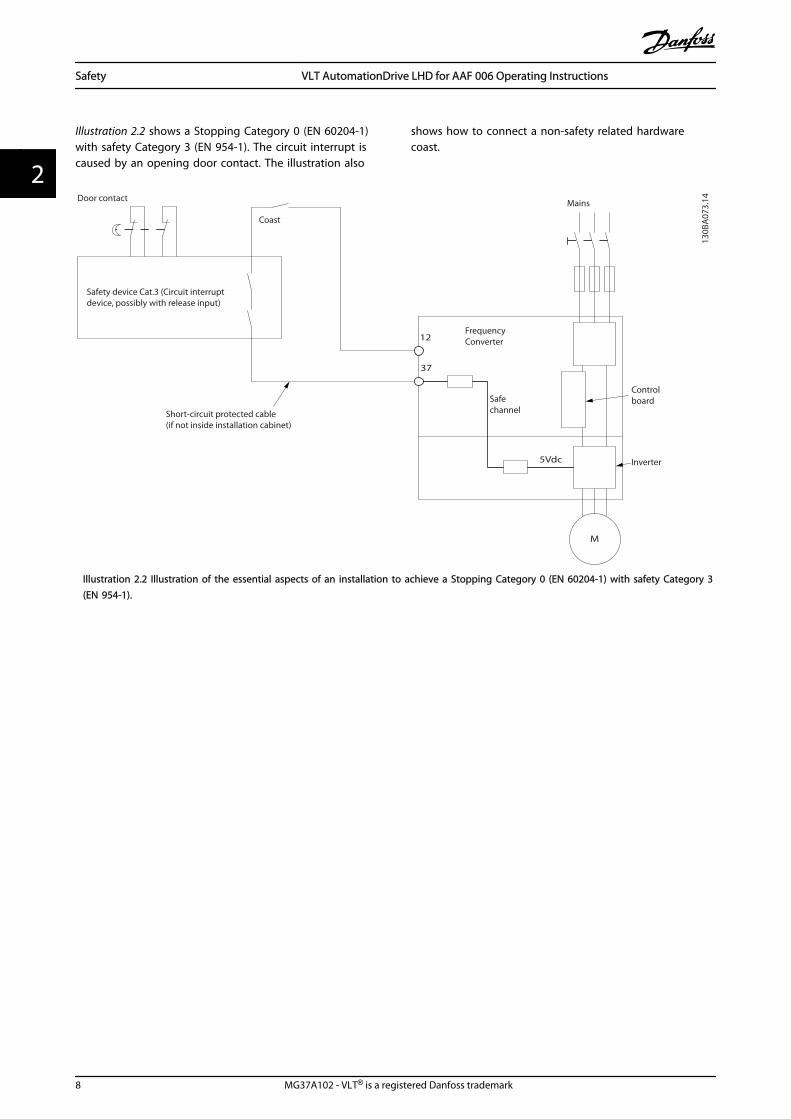
Illustration 2.2 shows a Stopping Category 0 (EN 60204-1)with safety Category 3 (EN 954-1). The circuit interrupt iscaused by an opening door contact. The illustration also
shows how to connect a non-safety related hardwarecoast.
Controlboard
Inverter
Safechannel
Safety device Cat.3 (Circuit interrupt device, possibly with release input)
Coast
Short-circuit protected cable(if not inside installation cabinet)
Door contact Mains
Frequency Converter
M
37
5Vdc
130B
A07
3.14
12
Illustration 2.2 Illustration of the essential aspects of an installation to achieve a Stopping Category 0 (EN 60204-1) with safety Category 3(EN 954-1).
Safety VLT AutomationDrive LHD for AAF 006 Operating Instructions
8 MG37A102 - VLT® is a registered Danfoss trademark
22

2.1.7 Safe Stop of the Frequency Converter
For versions fitted with a Safe Stop terminal 37 input, thefrequency converter can perform the safety function SafeTorque Off (As defined by draft CD IEC 61800-5-2) or StopCategory 0 (as defined in EN 60204-1).
It is designed and approved suitable for the requirementsof Safety Category 3 in EN 954-1. This functionality is calledSafe Stop. Before integration and use of Safe Stop in aninstallation, a thorough risk analysis on the installation
must be carried out in order to determine whether theSafe Stop functionality and safety category are appropriateand sufficient. In order to install and use the Safe Stopfunction in accordance with the requirements of SafetyCategory 3 in EN 954-1, the related information andinstructions of the Design Guide must be followed. Theinformation and instructions of the Operating Instructionsare not sufficient for a correct and safe use of the SafeStop functionality.
Illustration 2.3
Safety VLT AutomationDrive LHD for AAF 006 Operating Instructions
MG37A102 - VLT® is a registered Danfoss trademark 9
2 2

2.1.8 IT Mains
WARNINGIT mainsDo not connect frequency converters with RFI-filters tomains supplies with a voltage between phase and earth ofmore than 440 V for 400 Vs and 760 V for 690 Vconverters.For 400 V IT mains and delta earth (grounded leg), mainsvoltage may exceed 440 V between phase and earth.
14-50 RFI Filter can be used to disconnect the internal RFIcapacitors from the RFI filter to ground. 14-50 RFI Filter onboth the frequency converter and the filter must be turnedoff.
2.1.9 Disposal Instruction
Equipment containing electrical componentsmust not be disposed of together with domesticwaste.It must be separately collected with electricaland electronic waste according to local andcurrently valid legislation.
Table 2.1
Safety VLT AutomationDrive LHD for AAF 006 Operating Instructions
10 MG37A102 - VLT® is a registered Danfoss trademark
22

3 Introduction to the Low Harmonic Drive
3.1.1 Working Principle
The VLT Low Harmonic Drive is a VLT High Powerfrequency converter with an integrated active filter. Anactive filter is a device that actively monitors harmonic
distortion levels and injects compensative harmoniccurrent onto the line to cancel out the harmonics.
Mains380 to500 VAC
OptionalRFI
OptionalFuses
OptionalManualDisconnect
HI Reactor
Lm
Lm
Lm
Lac
Lac
Lac
ACContactor
Relay 12Control & AUXFeedback
Relay 12Control & AUXFeedback
Soft-Charge
ConverterSide Filter
Power Stage
AF CurrentSensors
CapacitorCurrent Sensors
Frequency converter
Main’s
3
33
CTs
NCRelay
Lc
Lc
Lc
Cef Cef Cef
Ref Ref Ref
Ir
Is
It
130b
b40
6.10
Illustration 3.1 Basic layout for the Low Harmonic Drive
3.1.2 IEEE519 Compliance
Low harmonic drives are designed to draw an idealsinusoidal current waveform from the supply grid with apower factor of 1. Where traditional non linear load drawspulse shaped currents the low harmonic drivecompensates that via the parallel filter path lowering thestress on the supply grid. The low harmonic drive meetsthe toughest harmonic standards and has a THiD of lessthan 5% at full load for <3% pre-distortion on a 3%unbalanced three-phased grid. The unit is designed tomeet IEEE519 recommendation for Isc/Il >20 for bothuneven and even individual harmonic levels. The filterportion of the low harmonic drives has a progressiveswitching frequency which leads to a wide frequencyspreads giving lower individual harmonic levels above the50th.
0 2 4 6 8 10 12 14 16 18 20 22 24 26 28 30 32 34 36 38 40 42 44 46 48 500
3
4
5
6
7
8
9
10
[n]
I [%]
1
2
130B
B448
.10
Illustration 3.2 Typical harmonic frequency spectrum and THDvalue at the mains terminals of the driven = harmonic order
⃟.....IEEE519 (Isc/IL>20) limits for individual harmonics
Introduction to the Low Har... VLT AutomationDrive LHD for AAF 006 Operating Instructions
MG37A102 - VLT® is a registered Danfoss trademark 11
3 3
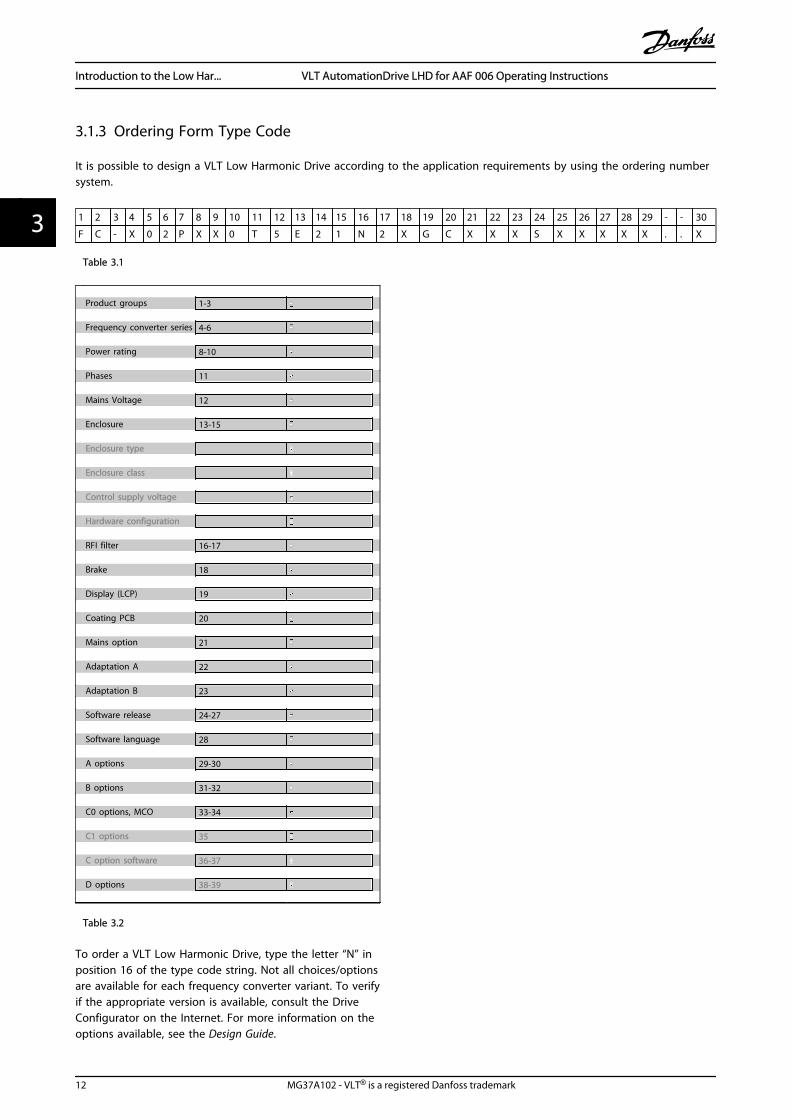
3.1.3 Ordering Form Type Code
It is possible to design a VLT Low Harmonic Drive according to the application requirements by using the ordering numbersystem.
1 2 3 4 5 6 7 8 9 10 11 12 13 14 15 16 17 18 19 20 21 22 23 24 25 26 27 28 29 - - 30
F C - X 0 2 P X X 0 T 5 E 2 1 N 2 X G C X X X S X X X X X . . X
Table 3.1
Product groups 1-3 Frequency converter series 4-6 Power rating 8-10 Phases 11 Mains Voltage 12 Enclosure 13-15 Enclosure type Enclosure class Control supply voltage Hardware configuration RFI filter 16-17 Brake 18 Display (LCP) 19 Coating PCB 20 Mains option 21 Adaptation A 22 Adaptation B 23 Software release 24-27 Software language 28 A options 29-30 B options 31-32 C0 options, MCO 33-34 C1 options 35 C option software 36-37 D options 38-39
Table 3.2
To order a VLT Low Harmonic Drive, type the letter “N” inposition 16 of the type code string. Not all choices/optionsare available for each frequency converter variant. To verifyif the appropriate version is available, consult the DriveConfigurator on the Internet. For more information on theoptions available, see the Design Guide.
Introduction to the Low Har... VLT AutomationDrive LHD for AAF 006 Operating Instructions
12 MG37A102 - VLT® is a registered Danfoss trademark
33
4 How to Install
4.1 How to Get Started
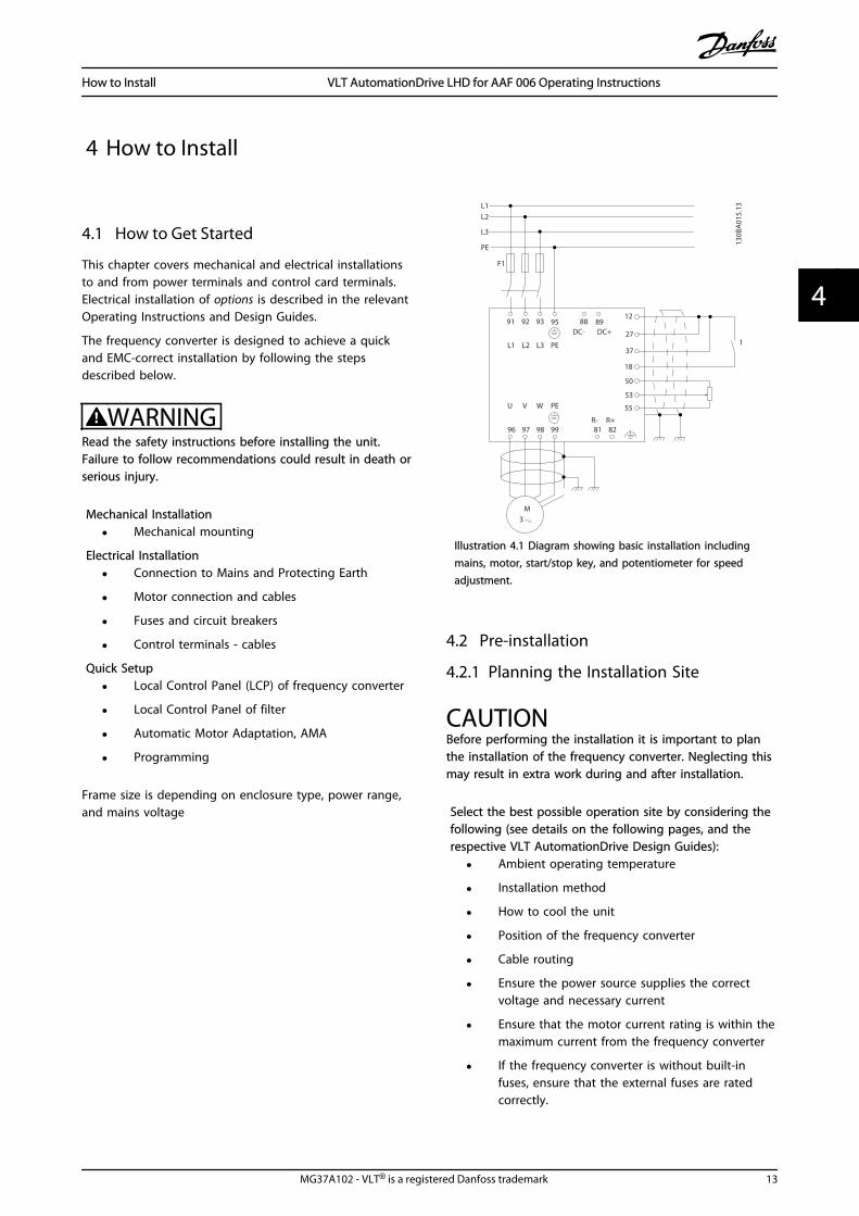
This chapter covers mechanical and electrical installationsto and from power terminals and control card terminals.Electrical installation of options is described in the relevantOperating Instructions and Design Guides.
The frequency converter is designed to achieve a quickand EMC-correct installation by following the stepsdescribed below.
WARNINGRead the safety instructions before installing the unit.Failure to follow recommendations could result in death orserious injury.
Mechanical Installation
• Mechanical mounting
Electrical Installation
• Connection to Mains and Protecting Earth
• Motor connection and cables
• Fuses and circuit breakers
• Control terminals - cables
Quick Setup
• Local Control Panel (LCP) of frequency converter
• Local Control Panel of filter
• Automatic Motor Adaptation, AMA
• Programming
Frame size is depending on enclosure type, power range,and mains voltage
M3
96 97 9998
37
91 92 9312
L1
W PEVU
F1
L2
L3
PE
130B
A01
5.13
1
18
81 82R+R-
95
55
50
53
27
88 89DC- DC+
L1 L2 PEL3
Illustration 4.1 Diagram showing basic installation includingmains, motor, start/stop key, and potentiometer for speedadjustment.
4.2 Pre-installation
4.2.1 Planning the Installation Site
CAUTIONBefore performing the installation it is important to planthe installation of the frequency converter. Neglecting thismay result in extra work during and after installation.
Select the best possible operation site by considering thefollowing (see details on the following pages, and therespective VLT AutomationDrive Design Guides):
• Ambient operating temperature
• Installation method
• How to cool the unit
• Position of the frequency converter
• Cable routing
• Ensure the power source supplies the correctvoltage and necessary current
• Ensure that the motor current rating is within themaximum current from the frequency converter
• If the frequency converter is without built-infuses, ensure that the external fuses are ratedcorrectly.
How to Install VLT AutomationDrive LHD for AAF 006 Operating Instructions
MG37A102 - VLT® is a registered Danfoss trademark 13
4 4
4.2.2 Receiving the Frequency Converter
When receiving the frequency converter make sure thatthe packaging is intact, and be aware of any damage thatmight have occurred to the unit during transport. In casedamage has occurred, contact immediately the shippingcompany to claim the damage.
4.2.3 Transportation and Unpacking
Before unpacking the frequency converter it isrecommended that it is located as close as possible to thefinal installation site.Remove the box and handle the frequency converter onthe pallet, as long as possible.
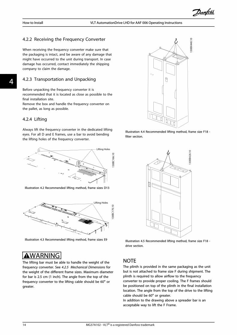
4.2.4 Lifting
Always lift the frequency converter in the dedicated liftingeyes. For all D and E frames, use a bar to avoid bendingthe lifting holes of the frequency converter.
Lifting Holes
130B
C16
6.10
Illustration 4.2 Recommended lifting method, frame sizes D13
130B
C17
0.10
Lifting Holes
Illustration 4.3 Recommended lifting method, frame sizes E9
WARNINGThe lifting bar must be able to handle the weight of thefrequency converter. See 4.2.5 Mechanical Dimensions forthe weight of the different frame sizes. Maximum diameterfor bar is 2.5 cm (1 inch). The angle from the top of thefrequency converter to the lifting cable should be 60° orgreater.
130B
X44
0.10
Illustration 4.4 Recommended lifting method, frame size F18 -filter section.
130B
B428
.10
Illustration 4.5 Recommended lifting method, frame size F18 -drive section.
NOTEThe plinth is provided in the same packaging as the unitbut is not attached to frame size F during shipment. Theplinth is required to allow airflow to the frequencyconverter to provide proper cooling. The F frames shouldbe positioned on top of the plinth in the final installationlocation. The angle from the top of the drive to the liftingcable should be 60° or greater.In addition to the drawing above a spreader bar is anacceptable way to lift the F Frame.
How to Install VLT AutomationDrive LHD for AAF 006 Operating Instructions
14 MG37A102 - VLT® is a registered Danfoss trademark
44

NOTEThe F frame will be shipped as 2 pieces. Instructions onhow to assemble the pieces can be found in4.3 Mechanical Installation.
How to Install VLT AutomationDrive LHD for AAF 006 Operating Instructions
MG37A102 - VLT® is a registered Danfoss trademark 15
4 4

4.2.5 Mechanical Dimensions
1780
.5 [7
0.1]
112.
5[4
.4]16
0.0
[6.3
]
1534
.5 [6
0.4]
977.
0 [3
8.5]
60.0
[6.3
]
304.
0 [1
2.0]
510.
0 [2
0.1] 30
4.0
[12.
0]13
9.0
[5.5
]
1755
.5 [6
9.1]
411.
0 [1
6.2]
251.
0 [9
.9]
301.
9 [1
1.9]
486.
4 [1
9.2]
627.
4 [2
4.7]
117.
5 [4
.6]
184.
5 [7
.3]
369.
0 [1
4.5]
130BC167.10
1021
.9 [4
0.2]
377.
8[1
4.9]
158
1[6
2.2]
Illus
trat
ion
4.6
Fra
me
Size
D13
How to Install VLT AutomationDrive LHD for AAF 006 Operating Instructions
16 MG37A102 - VLT® is a registered Danfoss trademark
44
2000.7[78.8]
184.5[7.3]369.0
[14.5]553.5[21.8] 600.0
[23.6]784.5[30.9] 969.0
[38.2]1153.5[45.4]
160.0[6.3]
160.0[6.3]
248.0[9.8]
725.0[28.5]
1043.0[41.1]
160.0[6.3]
493.5[19.4]
1200.0[47.2]
130B
C17
1.10
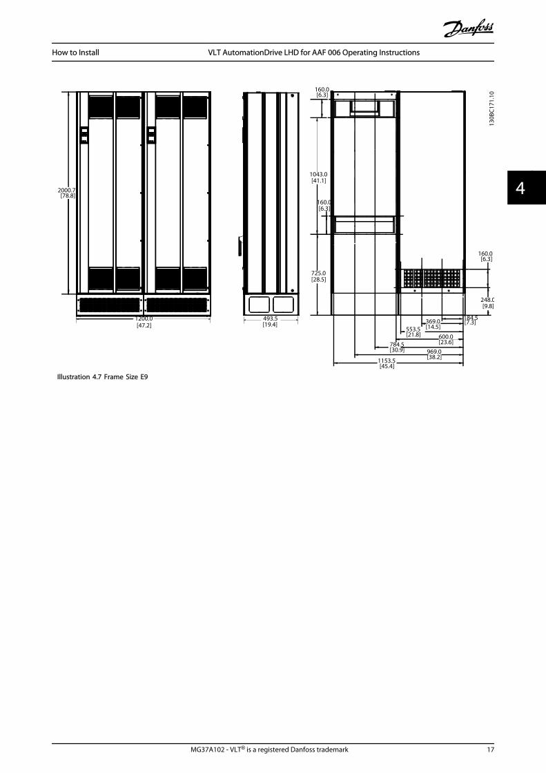
Illustration 4.7 Frame Size E9
How to Install VLT AutomationDrive LHD for AAF 006 Operating Instructions
MG37A102 - VLT® is a registered Danfoss trademark 17
4 4
2078.4 2278.4
130B
C17
4.10
2792.0[110]
605.8 [24]
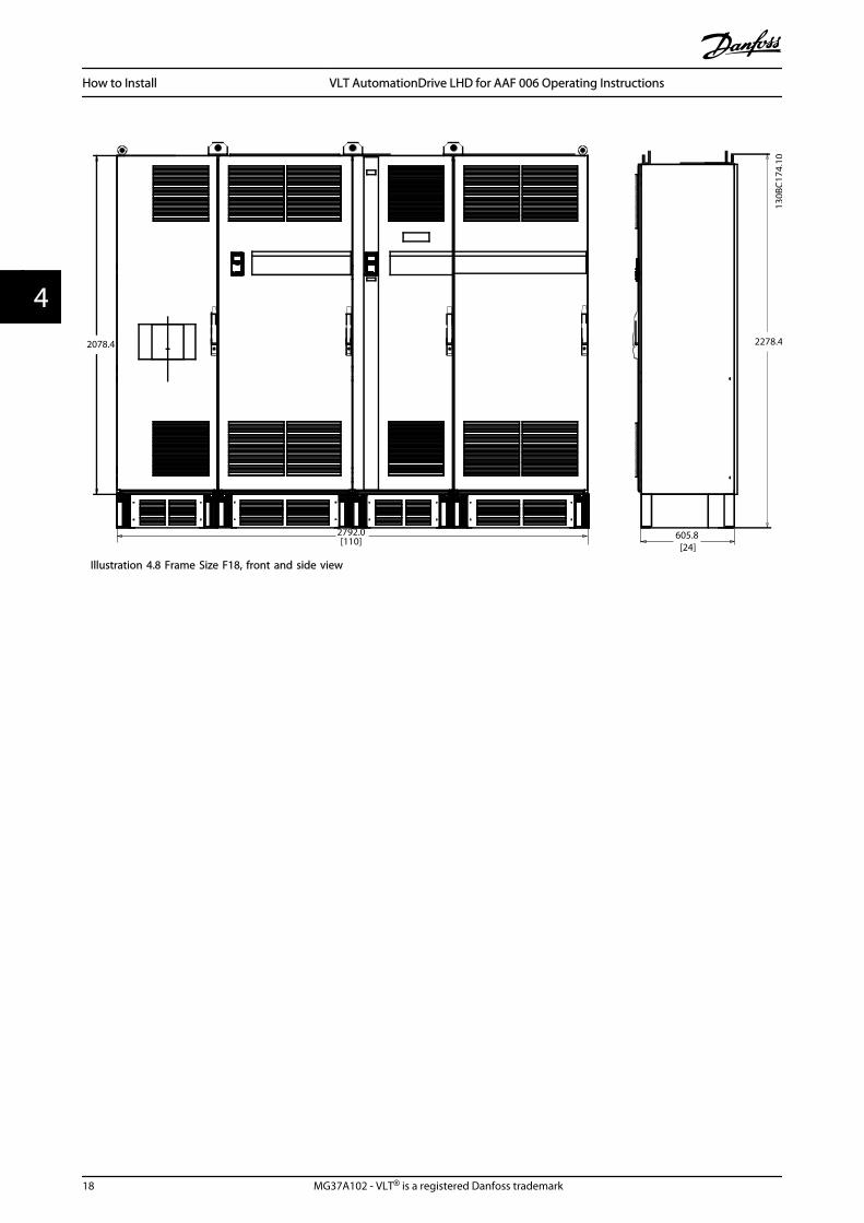
Illustration 4.8 Frame Size F18, front and side view
How to Install VLT AutomationDrive LHD for AAF 006 Operating Instructions
18 MG37A102 - VLT® is a registered Danfoss trademark
44
169.6[7]
183.4[7]
1576.7[62]
344.6[14]
2170.3[85]
183.0[7]
286.0[11]
468.9[18]
2107.6[83]
259.6[10]
315.5[12]
585.2[23]
130B
C17
5.10
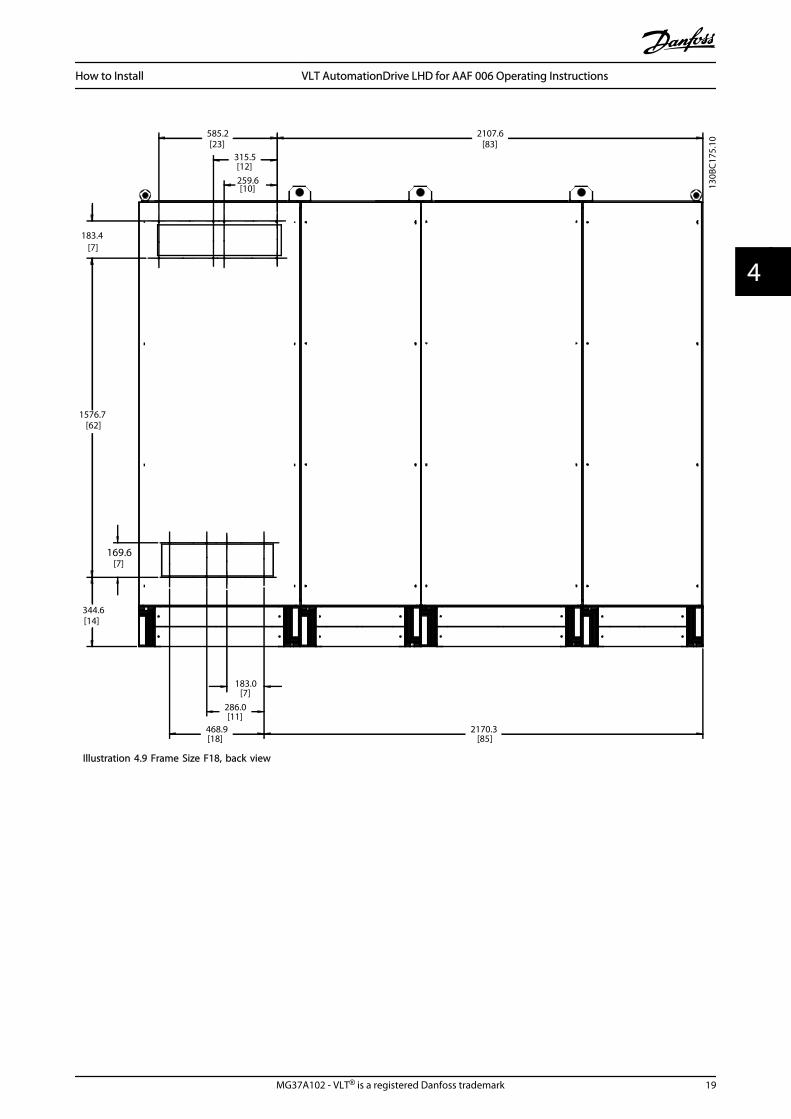
Illustration 4.9 Frame Size F18, back view
How to Install VLT AutomationDrive LHD for AAF 006 Operating Instructions
MG37A102 - VLT® is a registered Danfoss trademark 19
4 4

Mechanical Dimensions and Rated Power
Frame size D13 E9
Enclosure protectionIP 21/54 21/54*
NEMA Type 1/Type 12 Type 1/Type 12
High overload rated power - 160%overload torque
132 - 200 kW at 400 V(380 - 480 V)
250 - 400 kW at 400 V(380 - 480 V)
Drive Dimensions Height 1780.5 mm/70.1” 2000.7 mm/78.77”
Width 1021.9 mm/40.23” 1200 mm/47.24”
Depth 377.8 mm/14.87” 493.5 mm/19.43”
Max Weight 390 kg/860 lbs. 676 kg/1490 lbs.
ShippingWeight
435 kg/959 lbs. 721 kg/1590 lbs.
Table 4.1
Frame size F18
Enclosure protectionIP 21/54
NEMA Type 1
High overload rated power - 160% overloadtorque
450 - 630 kW at 400 V(380 - 480 V)
Drive Dimensions Height 2278.4 mm/89.70”
Width 2792 mm/109.92”
Depth 605.8 mm/23.85”
Max Weight 1900 kg/4189 lbs.
ShippingWeight
2262 kg/4987 lbs.
Table 4.2
4.3 Mechanical Installation
Preparation of the mechanical installation of the frequencyconverter must be done carefully to ensure a proper resultand to avoid additional work during installation. Starttaking a close look at the mechanical drawings at the endof this instruction to become familiar with the spacedemands.
4.3.1 Tools Needed
Tools needed for mechanical installation:
• Drill with 10 or 12 mm drill
• Tape measure
• Screw driver
• Wrench with relevant metric sockets (7-17 mm)
• Extensions to wrench
• Sheet metal punch for conduits or cable glands
• Lifting bar to lift the unit (rod or tube max. Ø 25mm (1 inch), able to lift minimum 1000 kg).
• Crane other lifting aid to place the unit inposition
• Torx T50 tool
4.3.2 General Considerations
SpaceEnsure proper space above and below the frequencyconverter to allow airflow and cable access. In additionspace in front of the unit must be considered to enableopening of the door of the panel.
68.1[2.7]
577.4[22.7]
398.2[15.7]
574.2[22.6]
130B
C16
5.10
Illustration 4.10 Space in front of IP21/IP54 enclosure type, framesize D13.
How to Install VLT AutomationDrive LHD for AAF 006 Operating Instructions
20 MG37A102 - VLT® is a registered Danfoss trademark
44

576.7[22.7]
104.7[4.1]
577.4[22.7]
577.4[22.7]
130B
C16
9.10
Illustration 4.11 Space in front of IP21/IP54 enclosure type, framesize E9.
562.0[22]108.0
[4]
163.0[6]
2X589.5[23] 2X 783.5
[31]
112.8[4]
264.3[10]
1486.0[59]716.0
[28]
621.5[24]
2066.9[81]
130B
C17
2.10
Illustration 4.12 Space in front of IP21/IP54 enclosure type, framesize F18.
Wire accessEnsure that proper cable access is present includingnecessary bending allowance.
NOTEAll cable lugs/ shoes must mount within the width of theterminal bus bar.
How to Install VLT AutomationDrive LHD for AAF 006 Operating Instructions
MG37A102 - VLT® is a registered Danfoss trademark 21
4 4
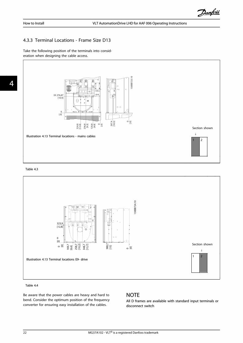
4.3.3 Terminal Locations - Frame Size D13
Take the following position of the terminals into consid-eration when designing the cable access.
3X 276,87[10.9]
0[.0]
267,
4[1
0.5] 0
[.0]
120,
8[4
.8]
236,
8[9
.3] 0
[.0]
324,
8[1
2.8]
130B
B723
.10
Illustration 4.13 Terminal locations - mains cables
Section shown
↓
1 2
Table 4.3
323,9[12,8]
0[0]
0 [0]
0 [0]
380,
7[1
5]
169,
7[6
,6]
258,
7[1
0,2]
348,
7[1
3,7]
130B
B724
.10
Illustration 4.13 Terminal locations E9- drive
Section shown
↓
1 2
Table 4.4
Be aware that the power cables are heavy and hard tobend. Consider the optimum position of the frequencyconverter for ensuring easy installation of the cables.
NOTEAll D frames are available with standard input terminals ordisconnect switch
How to Install VLT AutomationDrive LHD for AAF 006 Operating Instructions
22 MG37A102 - VLT® is a registered Danfoss trademark
44

4.3.4 Terminal Locations - Frame Size E9
Take the following position of the terminals into consid-eration when designing the cable access.
130B
B431
.10
332.5[13.1]
.0[.0]
.0 [.0]
.0 [.0]
407.
5[1
6.0]
332.
0[1
3.1]
88.0
[3.5
]16
8.0
[6.6
]
Illustration 4.13 Terminal locations Mains Cables
Section shown
↓
Table 4.5
FASTENER TORQUE FASTENER TORQUE
-R 81 +R 82
M8 9.6 NM (7 FT-LB)
FASTENER TORQUE M8 9.6 NM (7 FT-LB)
19 Nm (14 FT-LB)M10 19 N
W/T3 98W/T2 97U/T1 96
458,1[18.0]
322,5[12.7]
,0[.0]
,0 [.0]
,0 [.0]
527,
7[2
0.8]
525,
0]2
0.7]
443,
7[1
7.5]
412,
5[1
6.2]
300,
0[1
1.8]
187,
5[7
.4]
75,0
[3.0
]
280,
2[1
1.0]
153,
9[6
.1]
130B
B432
.10
Illustration 4.13 Terminal locations motor cables
Section shown
↓
Table 4.6
How to Install VLT AutomationDrive LHD for AAF 006 Operating Instructions
MG37A102 - VLT® is a registered Danfoss trademark 23
4 4

Note that the power cables are heavy and difficult tobend. Consider the optimum position of the frequencyconverter for ensuring easy installation of the cables.
Each terminal allows use of up to 4 cables with cable lugsor use of standard box lug. Earth is connected to relevanttermination point in the frequency converter.
104[4.1]
35[1.4]
10[0.4]0[0.0]
0[0.0]
40[1.6]
78[3.1]
0[0.0]
26[1.0]
26[1.0]
176FA27
1.10
B B
B B
A
A
Illustration 4.13 Terminal in details
NOTEPower connections can be made to positions A or B
How to Install VLT AutomationDrive LHD for AAF 006 Operating Instructions
24 MG37A102 - VLT® is a registered Danfoss trademark
44

4.3.5 Terminal Locations - Frame Size F18
Terminal locations - Filter
10.0[0.00
]76
.4[3.01]
128.4[5.05
]11
9.0[4.69
]17
1.0[6.73
]
294[11
.60]
344.0[13
.54]
3639
[14.33
]43
8.9[17
.28]
75.3[2.96]
150.3[5.92
]36
39[6.06]
219.6[18
.65]
0.0[0.00
]
244.4[9.62]
244.4[1.75]
939.0[36.97]
1031.4[40.61]
0.0[0.00]
134.6[5.30]
130B
A85
1.10
0.0[1.75]
Illustration 4.14 Terminal locations - Filter(Left side, front and right side view). The gland plate is 42 mm below .0 level.1) Earth ground bar
Section shown
↓
Table 4.7
How to Install VLT AutomationDrive LHD for AAF 006 Operating Instructions
MG37A102 - VLT® is a registered Danfoss trademark 25
4 4

Terminal locations - Rectifier
74.6
[2.9
]
0.0
[0.0
]
125.
8 [4
.95]
218.
6 [8
.61]
293.
6 [1
1.56
]
362.
6 [1
4.28
]
437.
6 [1
7.23
]
149.
6 [5
.89]
486.
6 [1
9.16
]
183.
4 [7
.22]
373.
4 [1
4.70
]
0.0 [0.00]
70.4 [2.77]
193.9 [7.64]
343.1 [13.51]
38.1
[1.5
0]0.
0 [0
.00]
90.1
[3.5
5]13
6.6
[5.3
8]18
8.6
[7.4
2] B A
435.5 [17.15]
LOAD SHARE LOCATIONDIM F1/F2 F3/F4
A 380.5 [14.98] 29.4 [1.16]B 432.5 [17.03] 81.4 [3.20]
1
2
3
130B
A84
8.11
CH22 CH22
R/L1 91 S/L2 92FASTENER TORQUE: M8 9.6 Nm (7 FT-LB)
T/L3 93FASTENER TORQUE: M10 19 Nm (14 FT-LB)
FASTENER TORQUE: M10 19 Nm (14 FT-LB)DC 89
FASTENER TORQUE: M10 19 Nm (14 FT-LB)DC 89
CH22 CH22 CH22 CH22CTI25MB CTI25MB
AUXAUX AUXAUXAUX
Illustration 4.14 Terminal locations - Rectifier(Left side, front and right side view). The gland plate is 42 mm below .0 level.1) Loadshare Terminal (-)2) Earth ground bar3) Loadshare Terminal (+)
Section shown
↓
Table 4.8
How to Install VLT AutomationDrive LHD for AAF 006 Operating Instructions
26 MG37A102 - VLT® is a registered Danfoss trademark
44
Terminal locations - Inverter
287.
4[1
1.32
]
0.0
[0.0
0]
339.
4[1
3.36
]
253.1 [9.96]
0.0 [0.00]
287.
4[1
1.32
]
0.0
[0.0
0]
339.
4[1
3.36
]
465.
6[1
8.33
]
465.
6[1
8.33
]
308.3 [12.14]
180.3 [7.10]
210.
1[8
.27]
0.0
[0.0
0]66
.4[2
.61]
181.
4[7
.14]
296.
4[1
1.67
]
431.
0[1
6.97
]
546.
0[2
1.50
]
661.
0[2
6.03
]
795.
7[3
1.33
]91
0.7
[35.
85]
1025
.7[4
0.38
]
246.
1[9
.69]
294.
1[1
1.58
]33
0.1
[13.
00]
574.
7[2
2.63
]61
0.7
[24.
04]
658.
7[2
5.93
]69
4.7
[27.
35]
939.
4[3
6.98
]97
5.4
[38.
40]
1023
.4[4
0.29
]
1059
.4[4
1.71
]
144.
3[5
.68]
219.
3[8
.63]
512.
3[2
0.17
]
587.
3[2
3.12
]
880.
3[3
4.66
]
955.
3[3
7.61
]
1
2
3
2
3
130B
A85
0.10
FASTENER TORQUE: MIO 19 Nm (14 FT -LB)
U/T1 96 V/T2 97 W/T3 98FASTENER TORQUE: MIO 19 Nm (14 FT -LB)
U/T1 96 V/T2 97 W/T3 98FASTENER TORQUE: MIO 19 Nm (14 FT -LB)
U/T1 96 V/T2 97 W/T3 98
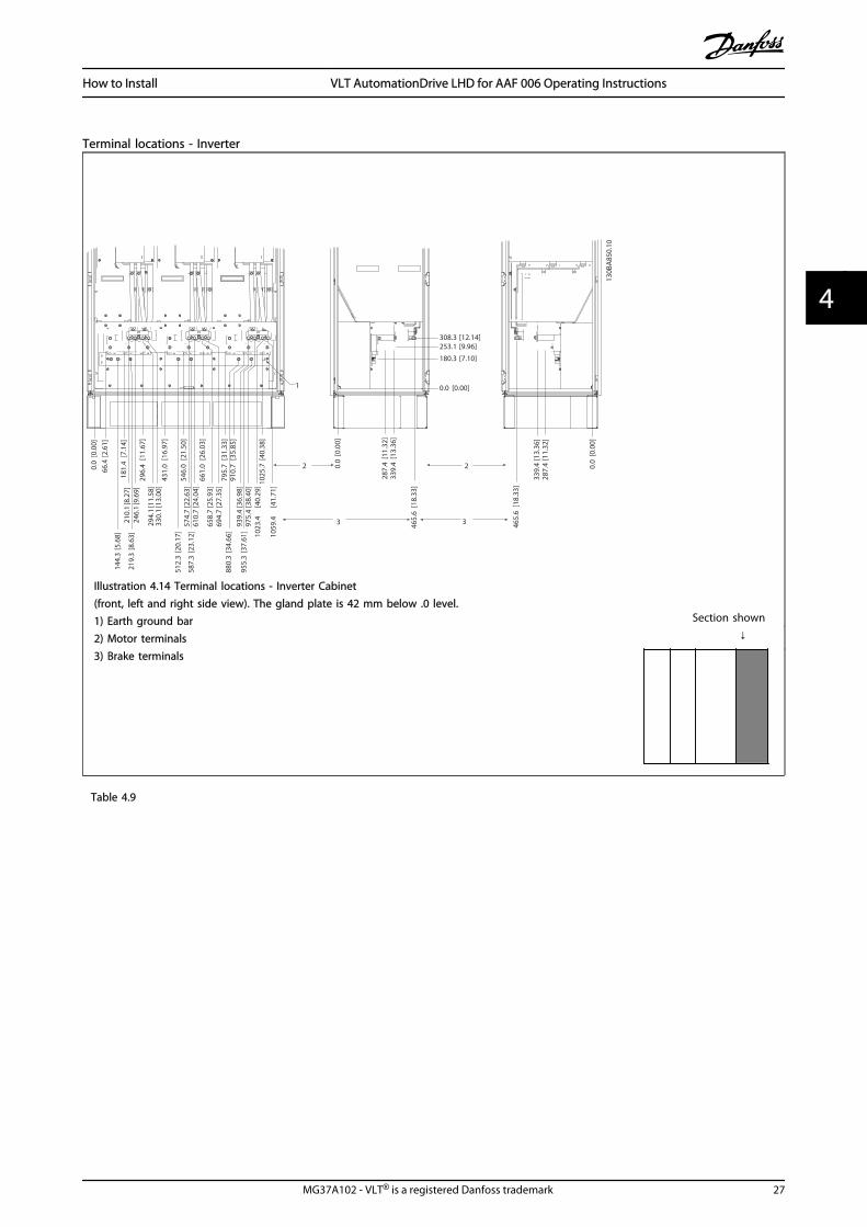
Illustration 4.14 Terminal locations - Inverter Cabinet(front, left and right side view). The gland plate is 42 mm below .0 level.1) Earth ground bar2) Motor terminals3) Brake terminals
Section shown
↓
Table 4.9
How to Install VLT AutomationDrive LHD for AAF 006 Operating Instructions
MG37A102 - VLT® is a registered Danfoss trademark 27
4 4
4.3.6 Cooling and Airflow
CoolingCooling can be obtained in different ways, by using thecooling ducts in the bottom and the top of the unit, bytaking air in and out the back of the unit or by combiningthe cooling possibilities.
Back coolingThe backchannel air can also be ventilated in and out theback of a Rittal TS8 enclosure. This offers a solution wherethe backchannel could take air from outside the facilityand return the heat loses outside the facility thus reducingair-conditioning requirements.
NOTEA door fan(s) is required on the enclosure to remove theheat losses not contained in the backchannel of the driveand any additional losses generated from othercomponents installed inside the enclosure. The totalrequired air flow must be calculated so that theappropriate fans can be selected. Some enclosuremanufacturers offer software for performing thecalculations (i.e. Rittal Therm software).
AirflowThe necessary airflow over the heat sink must be secured.The flow rate is shown in Table 4.10.
Enclosure protectionFrame size
Door fan(s) / Top fan airflowTotal airflow of multiple fans
Heatsink fan(s)Total airflow of multiple fans
IP21 / NEMA 1IP54 / NEMA 12
D13 510 m3/h (300 cfm) 2295 m3/h (1350 cfm)
E9 P250 680 m3/h (400 cfm) 2635 m3/h (1550 cfm)
E9 P315-P400 680 m3/h (400 cfm) 2975 m3/h (1750 cfm)
IP21 / NEMA 1 F18 4900 m3/h (2884 cfm) 6895 m3/h (4060 cfm)
Table 4.10 Heatsink Air Flow
NOTEFor the drive section, the fan runs for the followingreasons:
1. AMA
2. DC Hold
3. Pre-Mag
4. DC Brake
5. 60% of nominal current is exceeded
6. Specific heatsink temperature exceeded (powersize dependent)
7. Specific Power Card ambient temperatureexceeded (power size dependent)
8. Specific Control Card ambient temperatureexceeded
Once the fan is started it will run for minimum 10 minutes.
NOTEFor the active filter, the fan runs for the following reasons:
1. Active filter running
2. Active filter not running, but mains currentexceeding limit (power size dependent)
3. Specific heatsink temperature exceeded (powersize dependent)
4. Specific Power Card ambient temperatureexceeded (power size dependent)
5. Specific Control Card ambient temperatureexceeded
Once the fan is started it will run for minimum 10 minutes.
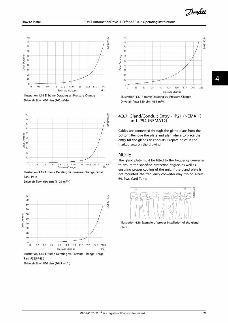
External ductsIf additional duct work is added externally to the Rittalcabinet the pressure drop in the ducting must becalculated. Use the charts below to derate the frequencyconverter according to the pressure drop.
How to Install VLT AutomationDrive LHD for AAF 006 Operating Instructions
28 MG37A102 - VLT® is a registered Danfoss trademark
44
90
80
70
60
50
40
30
20
10
0 0 0.5 4.9 13 27.3 45.9 66 89.3 115.7 147
(%)
(Pa)Pressure Increase
Driv
e D
erat
ing
130B
B007
.10
Illustration 4.14 D frame Derating vs. Pressure Change
Drive air flow: 450 cfm (765 m3/h)
90
80
70
60
50
40
30
20
10
0
(%)
Driv
e D
erat
ing
0 0 0.1 3.6 9.8 21.5 43.4 76 237.5 278.9(Pa)Pressure Change
130B
B010
.10
147.1
Illustration 4.15 E frame Derating vs. Pressure Change (SmallFan), P315
Drive air flow: 650 cfm (1105 m3/h)
90
80
70
60
50
40
30
20
10
0
(%)
Driv
e D
erat
ing
0 0.2 0.6 2.2 5.8 11.4 18.1 30.8 152.8 210.8(Pa)Pressure Change
130B
B011
.10
69.5
Illustration 4.16 E frame Derating vs. Pressure Change (LargeFan) P355-P450
Drive air flow: 850 cfm (1445 m3/h)
90
80
70
60
50
40
30
20
10
0
(%)
Driv
e D
erat
ing
0 25 50 75 100 125 150 175 225
130B
B190
.10
200
Pressure Change
Illustration 4.17 F frame Derating vs. Pressure Change
Drive air flow: 580 cfm (985 m3/h)
4.3.7 Gland/Conduit Entry - IP21 (NEMA 1)and IP54 (NEMA12)
Cables are connected through the gland plate from thebottom. Remove the plate and plan where to place theentry for the glands or conduits. Prepare holes in themarked area on the drawing.
NOTEThe gland plate must be fitted to the frequency converterto ensure the specified protection degree, as well asensuring proper cooling of the unit. If the gland plate isnot mounted, the frequency converter may trip on Alarm69, Pwr. Card Temp
130B
B073
.10
Illustration 4.18 Example of proper installation of the glandplate.
How to Install VLT AutomationDrive LHD for AAF 006 Operating Instructions
MG37A102 - VLT® is a registered Danfoss trademark 29
4 4

187.8 [7.4]
105.6 [4.2]
380.0 [15.0]
600.0 [23.6]
560.0 [22.0]
20.0 [.8]
55.9 [2.2]
246.0 [9.7]
181.9 [7.2]
350.0 [13.8]
636.9 [25.1]
350.0 [13.8]
130B
C16
4.10
1
Illustration 4.19 Frame Size D13
361.7[14.2]
61.4[2.4]560.0
[22.0]
600.0[23.6]
560.0[22.0]
20.0[.8]
154.8[6.1]
257.6[10.1]
40.0[1.6]
2x520.0[20.5]
640.0[25.2]
1
130B
C16
8.10
Illustration 4.20 Frame Size E9
How to Install VLT AutomationDrive LHD for AAF 006 Operating Instructions
30 MG37A102 - VLT® is a registered Danfoss trademark
44

176FA26
9.10
Illustration 4.21 Mounting of Bottom Plate, Frame Size E9
The bottom plate of the E frame can be mounted fromeither in- or outside of the enclosure, allowing flexibility inthe installation process, i.e. if mounted from the bottom
the glands and cables can be mounted before thefrequency converter is placed on the pedestal.
32.5[1]
533.0[21]
733.0[29]
533.0[21]
733.0[29]
598.0[24]
1396.0[55]
1994.0[79]
535.0[21]
34.8[1]
1
130B
C17
3.10
Illustration 4.22
Cable entries viewed from the bottom of the frequencyconverter1) Mains cable connection2) Motor cable connection
How to Install VLT AutomationDrive LHD for AAF 006 Operating Instructions
MG37A102 - VLT® is a registered Danfoss trademark 31
4 4

4.3.8 IP21 Drip Shield Installation (Framesize D)
To comply with the IP21 rating, a separate drip shield isto be installed as explained below:
• Remove the two front screws
• Insert the drip shield and replace screws
• Torque the screws to 5,6 Nm (50 in-lbs)
NOTEDrip shield is necessary on both filter and frequencyconverter section.
176FA28
5.10
Illustration 4.23 Drip shield installation.
↓ ↓
Table 4.11
4.4 Field Installation of Options
4.4.1 Installation of Input Plate Options
This section is for the field installation of input option kitsavailable for frequency converters in all D and E frames.Do not attempt to remove RFI filters from input plates.Damage may occur to RFI filters if they are removed fromthe input plate.
NOTEWhere RFI filters are available, there are two different typeof RFI filters depending on the input plate combinationand the RFI filters interchangeable. Field installable kits incertain cases are the same for all voltages.
380-480 V380-500 V
Fuses Disconnect Fuses RFI RFI Fuses RFI DisconnectFuses
D13 176F8443 176F8441 176F8445 176F8449 176F8447
E9 FC 102/ 202: 315 kWFC 302: 250 kW
176F0253 176F0255 176F0257 176F0258 176F0260
FC 102/ 202: 355-450kWFC 302: 315-400 kW
176F0254 176F0256 176F0257 176F0259 176F0262
Table 4.12
NOTEFor further information, please see the Instruction Sheet, 175R5795
How to Install VLT AutomationDrive LHD for AAF 006 Operating Instructions
32 MG37A102 - VLT® is a registered Danfoss trademark
44

4.4.2 Installation of Mains Shield forFrequency Converters
The mains shield is for installation with D and E framesand satisfy BG-4 requirements.
Ordering numbers:D frames: 176F0799E frames: 176F1851
NOTEFor further information, please see the Instruction Sheet,175R5923
4.5 Frame Size F Panel Options
Space Heaters and ThermostatMounted on the cabinet interior of frame size F frequencyconverters, space heaters controlled via automaticthermostat help control humidity inside the enclosure,extending the lifetime of drive components in dampenvironments. The thermostat default settings turn on theheaters at 10° C (50° F) and turn them off at 15.6° C (60°F).
Cabinet Light with Power OutletA light mounted on the cabinet interior of frame size Ffrequency converters increase visibility during servicingand maintenance. The housing the light includes a poweroutlet for temporarily powering tools or other devices,available in two voltages:
• 230 V, 50 Hz, 2.5 A, CE/ENEC
• 120 V, 60 Hz, 5 A, UL/cUL
Transformer Tap SetupIf the Cabinet Light & Outlet and/or the Space Heaters &Thermostat are installed Transformer T1 requires it taps tobe set to the proper input voltage. A 380-480/500 Vfrequency converter will initially be set to the 525 V tapand a 525-690 V frequency converter will be set to the 690V tap to insure no over-voltage of secondary equipmentoccurs if the tap is not changed prior to power beingapplied. See Table 4.13 to set the proper tap at terminal T1located in the rectifier cabinet. For location in thefrequency converter, see Illustration 4.14.
Input Voltage Range Tap to Select
380 V-440 V 400 V
441 V-490 V 460 V
Table 4.13 Tap Setup
NAMUR TerminalsNAMUR is an international association of automationtechnology users in the process industries, primarilychemical and pharmaceutical industries in Germany.Selection of this option provides terminals organized andlabeled to the specifications of the NAMUR standard for
drive input and output terminals. This requires MCB 112PTC Thermistor Card and MCB 113 Extended Relay Card.
RCD (Residual Current Device)Uses the core balance method to monitor ground faultcurrents in grounded and high-resistance groundedsystems (TN and TT systems in IEC terminology). There is apre-warning (50% of main alarm set-point) and a mainalarm set-point. Associated with each set-point is an SPDTalarm relay for external use. Requires an external “window-type” current transformer (supplied and installed bycustomer).
• Integrated into the drive’s safe-stop circuit
• IEC 60755 Type B device monitors AC, pulsed DC,and pure DC ground fault currents
• LED bar graph indicator of the ground faultcurrent level from 10–100% of the set-point
• Fault memory
• TEST/RESET key
Insulation Resistance Monitor (IRM)Monitors the insulation resistance in ungrounded systems(IT systems in IEC terminology) between the system phaseconductors and ground. There is an ohmic pre-warningand a main alarm set-point for the insulation level.Associated with each set-point is an SPDT alarm relay forexternal use.
NOTEOnly one insulation resistance monitor can be connectedto each ungrounded (IT) system.
• Integrated into the frequency converter’s safe-stop circuit
• LCD display of the ohmic value of the insulationresistance
• Fault Memory
• [Info], [Test], and [Reset] buttons
IEC Emergency Stop with Pilz Safety RelayIncludes a redundant 4-wire emergency-stop push-keymounted on the front of the enclosure and a Pilz relay thatmonitors it in conjunction with the frequency converter’ssafe-stop circuit and the mains contactor located in theoptions cabinet.
Manual Motor StartersProvide 3-phase power for electric blowers often requiredfor larger motors. Power for the starters is provided fromthe load side of any supplied contactor, circuit breaker, ordisconnect switch. Power is fused before each motorstarter, and is off when the incoming power to thefrequency converter is off. Up to two starters are allowed(one if a 30 A, fuse-protected circuit is ordered). Integratedinto the frequency converter’s safe-stop circuit.Unit features include:
How to Install VLT AutomationDrive LHD for AAF 006 Operating Instructions
MG37A102 - VLT® is a registered Danfoss trademark 33
4 4

• Operation switch (on/off)
• Short-circuit and overload protection with testfunction
• Manual reset function
30 Ampere, Fuse-Protected Terminals
• 3-phase power matching incoming mains voltagefor powering auxiliary customer equipment
• Not available if two manual motor starters areselected
• Terminals are off when the incoming power tothe drive is off
• Power for the fused protected terminals will beprovided from the load side of any suppliedcontactor, circuit breaker, or disconnect switch.
24 V DC Power Supply
• 5 amp, 120 W, 24 V DC
• Protected against output over-current, overload,short circuits, and over-temperature
• For powering customer-supplied accessorydevices such as sensors, PLC I/O, contactors,temperature probes, indicator lights, and/or otherelectronic hardware
• Diagnostics include a dry DC-ok contact, a greenDC-ok LED, and a red overload LED
External Temperature MonitoringDesigned for monitoring temperatures of external systemcomponents, such as the motor windings and/or bearings.Includes eight universal input modules plus two dedicatedthermistor input modules. All ten modules are integratedinto the frequency converter’s safe-stop circuit and can bemonitored via a fieldbus network (requires the purchase ofa separate module/bus coupler).
Universal inputs (8)Signal types:
• RTD inputs (including Pt100), 3-wire or 4-wire
• Thermocouple
• Analog current or analog voltage
Additional features:
• One universal output, configurable for analogvoltage or analog current
• Two output relays (N.O.)
• Dual-line LC display and LED diagnostics
• Sensor lead wire break, short-circuit, and incorrectpolarity detection
• Interface setup software
Dedicated thermistor inputs (2)Features:
• Each module capable of monitoring up to sixthermistors in series
• Fault diagnostics for wire breakage or short-circuits of sensor leads
• ATEX/UL/CSA certification
• A third thermistor input can be provided by thePTC Thermistor Option Card MCB 112, ifnecessary
4.6 Electrical Installation
4.6.1 Power Connections
Cabling and Fusing
NOTECables GeneralAll cabling must comply with national and localregulations on cable cross-sections and ambienttemperature. UL applications require 75° C copperconductors. 75 and 90° C copper conductors are thermallyacceptable for the frequency converter to use in non ULapplications.
The power cable connections are situated as shown below.Dimensioning of cable cross section must be done inaccordance with the current ratings and local legislation.See 8.1.1 Cable Lengths and Cross Sections: for details.
For protection of the frequency converter, therecommended fuses must be used or the unit must bewith built-in fuses. Recommended fuses can be seen in thetables of the fuse section. Always ensure that proper fusingis made according to local regulation.
The mains connection is fitted to the mains switch if this isincluded.
3 Phase
power
input
130B
A02
6.10
91 (L1)
92 (L2)
93 (L3)
95 PE
Illustration 4.23
How to Install VLT AutomationDrive LHD for AAF 006 Operating Instructions
34 MG37A102 - VLT® is a registered Danfoss trademark
44

NOTETo comply with EMC emission specifications, screened/armoured cables are recommended. If an unscreened/unarmoured cable is used, see 4.6.13 Power and ControlWiring for Unscreened Cables.
See 8 General Specifications for correct dimensioning ofmotor cable cross-section and length.
Screening of cables:Avoid installation with twisted screen ends (pigtails). Theyspoil the screening effect at higher frequencies. If it isnecessary to break the screen to install a motor isolator ormotor contactor, the screen must be continued at thelowest possible HF impedance.
Connect the motor cable screen to both the de-couplingplate of the frequency converter and to the metal housingof the motor.
Make the screen connections with the largest possiblesurface area (cable clamp). This is done by using thesupplied installation devices within the frequencyconverter.
Cable-length and cross-section:The frequency converter has been EMC tested with a givenlength of cable. Keep the motor cable as short as possibleto reduce the noise level and leakage currents.
Switching frequency:When frequency converters are used together with Sine-wave filters to reduce the acoustic noise from a motor, theswitching frequency must be set according to theinstruction in 14-01 Switching Frequency.
Term. no. 96 97 98 99
U V W PE1) Motor voltage 0-100% of mains voltage.3 wires out of motor
U1 V1 W1PE1)
Delta-connectedW2 U2 V2 6 wires out of motor
U1 V1 W1 PE1) Star-connected U2, V2, W2U2, V2 and W2 to be interconnected separately.
Table 4.14
1)Protected Earth Connection
NOTEIn motors without phase insulation paper or otherinsulation reinforcement suitable for operation withvoltage supply (such as a frequency converter), fit a Sine-wave filter on the output of the frequency converter.
U V W 175Z
A11
4.10VU W
96 97 98 96 97 98
Illustration 4.24
How to Install VLT AutomationDrive LHD for AAF 006 Operating Instructions
MG37A102 - VLT® is a registered Danfoss trademark 35
4 4

1
2
3
4
5
130B
C20
8.10
Illustration 4.25 Frame size D13
1) RFI 4) Motor
2) Line U V W
R S T 96 97 98
L1 L2 L3 T1 T2 T3
3) Brake option 5) Load sharing option
-R +R -DC +DC
81 82 88 89
6) AUX Fan
100 101 102 103
L1 L2 L1 L2
Table 4.15
How to Install VLT AutomationDrive LHD for AAF 006 Operating Instructions
36 MG37A102 - VLT® is a registered Danfoss trademark
44

1
130B
C20
9.10
Illustration 4.26 Position of Earth Terminals
1 Earth/ground
Table 4.16
How to Install VLT AutomationDrive LHD for AAF 006 Operating Instructions
MG37A102 - VLT® is a registered Danfoss trademark 37
4 4
1
2
3
4
513
0BC21
0.11
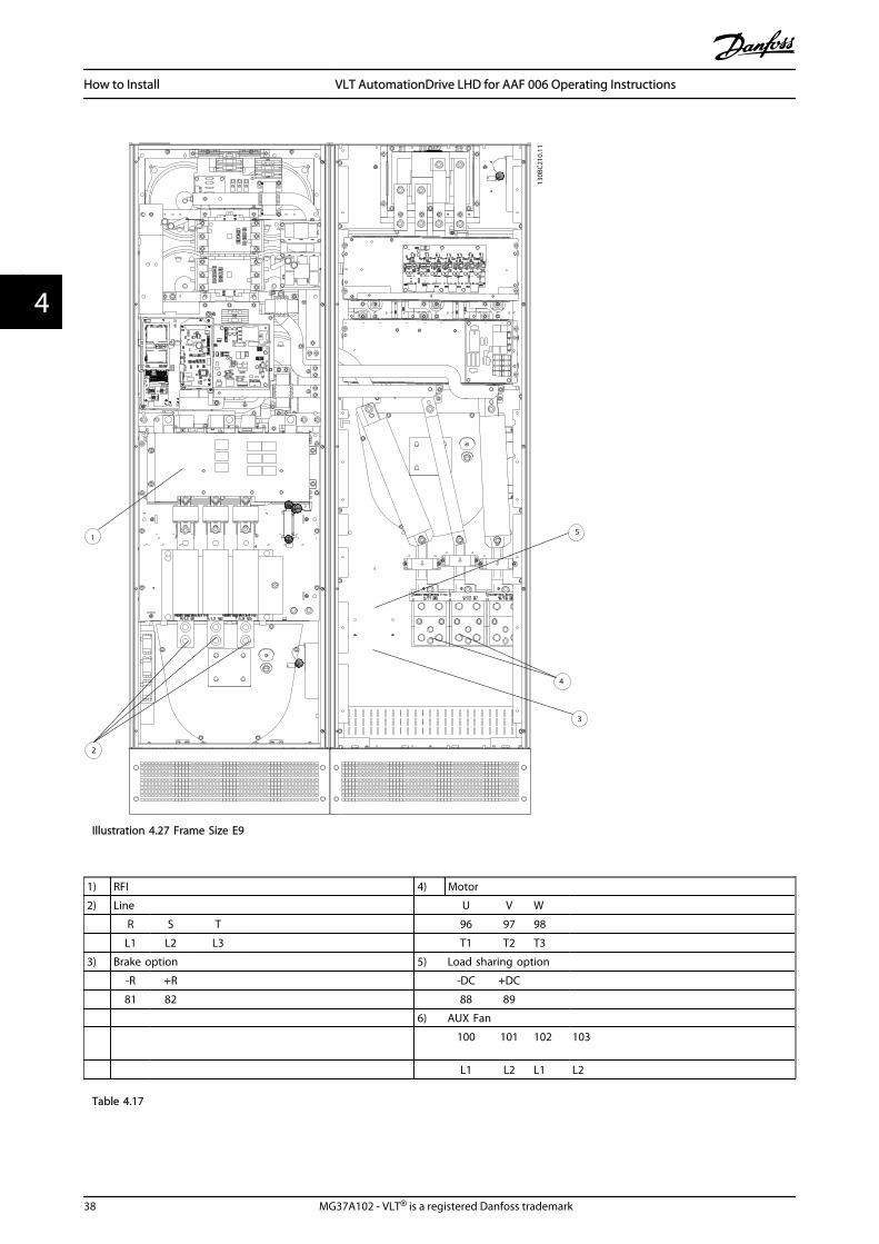
Illustration 4.27 Frame Size E9
1) RFI 4) Motor
2) Line U V W
R S T 96 97 98
L1 L2 L3 T1 T2 T3
3) Brake option 5) Load sharing option
-R +R -DC +DC
81 82 88 89
6) AUX Fan
100 101 102 103
L1 L2 L1 L2
Table 4.17
How to Install VLT AutomationDrive LHD for AAF 006 Operating Instructions
38 MG37A102 - VLT® is a registered Danfoss trademark
44

1
130B
C21
1.10
Illustration 4.28 Position of Earth Terminals
1 Earth/ground
Table 4.18
How to Install VLT AutomationDrive LHD for AAF 006 Operating Instructions
MG37A102 - VLT® is a registered Danfoss trademark 39
4 4
130B
X44
3
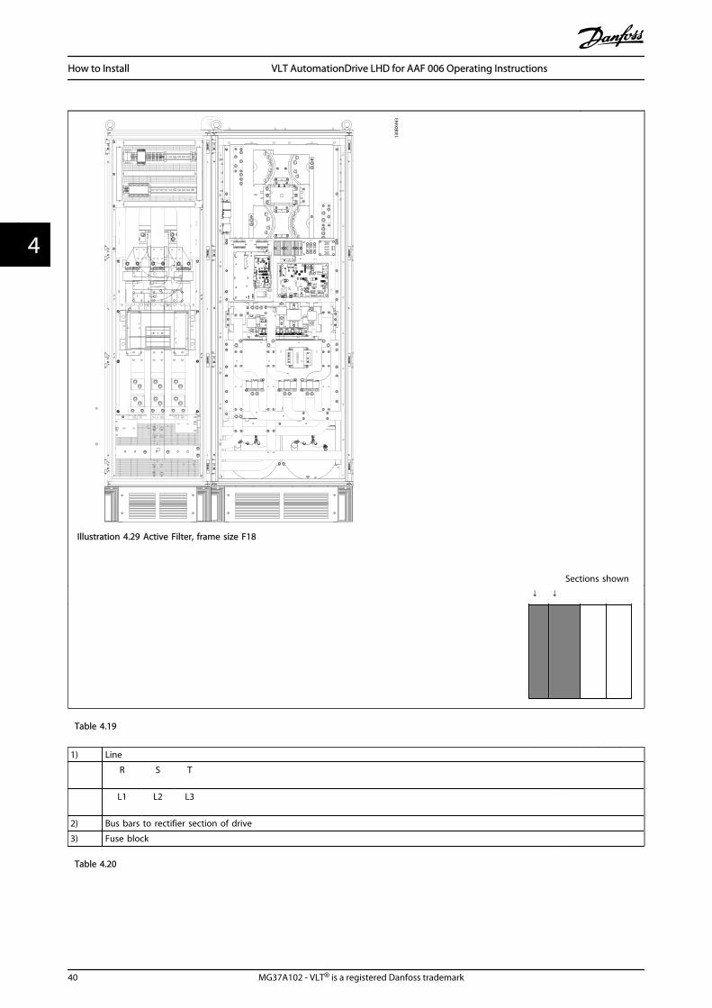
Illustration 4.29 Active Filter, frame size F18
Sections shown
↓ ↓
Table 4.19
1) Line
R S T
L1 L2 L3
2) Bus bars to rectifier section of drive
3) Fuse block
Table 4.20
How to Install VLT AutomationDrive LHD for AAF 006 Operating Instructions
40 MG37A102 - VLT® is a registered Danfoss trademark
44

+DC 89FASTENER TORQUE: M10 19Nm (14 FT -LB)
+DC 89
130B
A86
0.10
1
5
4
3
2
8
10
9
FUSE
C J3ONNECT
CH22 CH22 CH22CTI25MB
FASTENER TORQUE: M10 19Nm (14 FT -LB)
CTI25MBCH22 CH22 CH22
7
6
Illustration 4.29 Rectifier Cabinet, frame size F18
Section shown ↓
Table 4.21
1) 24 V DC, 5 A 5) Loadsharing
T1 Output Taps -DC +DC
Temp Switch 88 89
106 104 105 6) Control Transformer Fuses (2 or 4 pieces). See 4.6.14 Fuses for part numbers
2) Manual Motor Starters 7) SMPS Fuse. See 4.6.14 Fuses for part numbers
3) 30 A Fuse Protected Power Terminals 8) Manual Motor Controller fuses (3 or 6 pieces). See 4.6.14 Fuses for part numbers
4) Connection point to filter 9) Line Fuses, F1 and F2 frame (3 pieces). See 4.6.14 Fuses for part numbers
R S T 10) 30 Amp Fuse Protected Power fuses
L1 L2 L3
Table 4.22
How to Install VLT AutomationDrive LHD for AAF 006 Operating Instructions
MG37A102 - VLT® is a registered Danfoss trademark 41
4 4

2
5
6
4, 8, 9
130B
A86
1.111
Illustration 4.29 Inverter Cabinet, frame size F18
Section shown
↓
Table 4.23
1) External Temperature Monitoring 6) Motor
2) AUX Relay U V W
01 02 03 96 97 98
04 05 06 T1 T2 T3
3) NAMUR 7) NAMUR Fuse. See 4.6.14 Fuses for part numbers
4) AUX Fan 8) Fan Fuses. See 4.6.14 Fuses for part numbers
100 101 102 103 9) SMPS Fuses. See 4.6.14 Fuses for part numbers
L1 L2 L1 L2
5) Brake
-R +R
81 82
Table 4.24
How to Install VLT AutomationDrive LHD for AAF 006 Operating Instructions
42 MG37A102 - VLT® is a registered Danfoss trademark
44
4.6.2 Earthing
The following basic issues need to be considered wheninstalling a frequency converter, so as to obtain electro-magnetic compatibility (EMC).
• Safety earthing: The frequency converter has ahigh leakage current and must be earthedappropriately for safety reasons. Apply localsafety regulations.
• High-frequency earthing: Keep the earth wireconnections as short as possible.
Connect the different earth systems at the lowest possibleconductor impedance. The lowest possible conductorimpedance is obtained by keeping the conductor as shortas possible and by using the greatest possible surface area.The metal cabinets of the different devices are mountedon the cabinet rear plate using the lowest possible HFimpedance. This avoids having different HF voltages forthe individual devices and avoids the risk of radiointerference currents running in connection cables thatmay be used between the devices. The radio interferencewill have been reduced.In order to obtain a low HF impedance, use the fasteningbolts of the devices as HF connection to the rear plate. It isnecessary to remove insulating paint or similar from thefastening points.
4.6.3 Extra Protection (RCD)
ELCB relays, multiple protective earthing or earthing canbe used as extra protection, provided that local safetyregulations are complied with.
In the case of an earth fault, a DC component maydevelop in the fault current.
If ELCB relays are used, local regulations must be observed.Relays must be suitable for protection of 3-phaseequipment with a bridge rectifier and for a brief dischargeon power-up.
See also the section Special Conditions in VLT® Automa-tionDrive Design Guide, MG33BXYY.
4.6.4 RFI Switch
Mains supply isolated from earthIf the frequency converter is supplied from an isolatedmains source ( IT mains, floating delta and grounded delta)or TT/TN-S mains with grounded leg, the RFI switch isrecommended to be turned off (OFF) 1) via 14-50 RFI Filteron the frequency converter and 14-50 RFI Filter on thefilter. For further reference, see IEC 364-3. In case optimumEMC performance is needed, parallel motors are connected
or the motor cable length is above 25 m, it isrecommended to set 14-50 RFI Filter to [ON].1) Not available for 525-600/690 V frequency converters inframe sizes D, E and F.In OFF, the internal RFI capacities (filter capacitors)between the chassis and the intermediate circuit are cutoff to avoid damage to the intermediate circuit and toreduce the earth capacity currents (according to IEC61800-3).Also refer to the application note VLT on IT mains, MN.90.CX.02. It is important to use isolation monitors that arecapable for use together with power electronics (IEC61557-8).
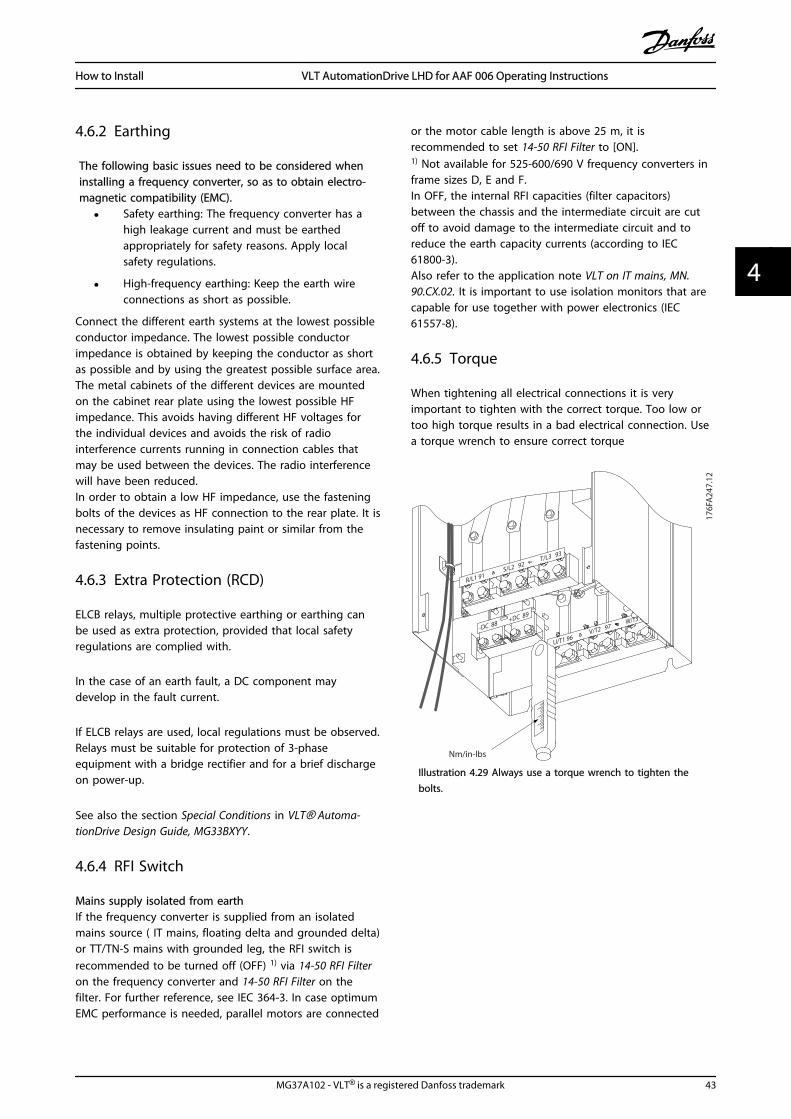
4.6.5 Torque
When tightening all electrical connections it is veryimportant to tighten with the correct torque. Too low ortoo high torque results in a bad electrical connection. Usea torque wrench to ensure correct torque
176F
A24
7.12
Nm/in-lbs
-DC 88+DC 89
R/L1 91S/L2 92
T/L3 93
U/T1 96V/T2 97
W/T3
Illustration 4.29 Always use a torque wrench to tighten thebolts.
How to Install VLT AutomationDrive LHD for AAF 006 Operating Instructions
MG37A102 - VLT® is a registered Danfoss trademark 43
4 4
Frame size Terminal Torque Bolt size
D
MainsMotor
19-40 Nm(168-354 in-lbs)
M10
Load sharingBrake
8.5-20.5 Nm(75-181 in-lbs)
M8
E
MainsMotorLoad sharing
19-40 Nm(168-354 in-lbs)
M10
Brake 8.5-20.5 Nm(75-181 in-lbs)
M8
F
MainsMotor
19-40 Nm(168-354 in-lbs)
M10
Load sharingBrakeRegen
19-40 Nm(168-354 in-lbs)8.5-20.5 Nm(75-181 in-lbs)8.5-20.5 Nm(75-181 in-lbs)
M10M8M8
Table 4.25 Torque for terminals
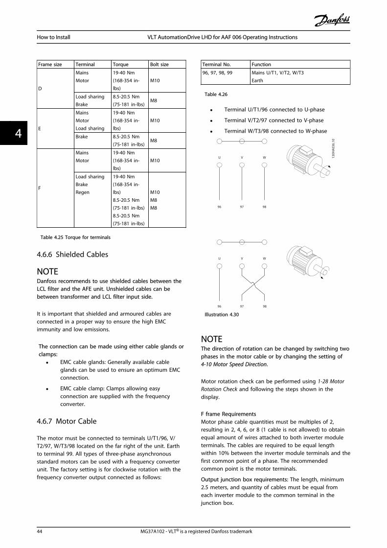
4.6.6 Shielded Cables
NOTEDanfoss recommends to use shielded cables between theLCL filter and the AFE unit. Unshielded cables can bebetween transformer and LCL filter input side.
It is important that shielded and armoured cables areconnected in a proper way to ensure the high EMCimmunity and low emissions.
The connection can be made using either cable glands orclamps:
• EMC cable glands: Generally available cableglands can be used to ensure an optimum EMCconnection.
• EMC cable clamp: Clamps allowing easyconnection are supplied with the frequencyconverter.
4.6.7 Motor Cable
The motor must be connected to terminals U/T1/96, V/T2/97, W/T3/98 located on the far right of the unit. Earthto terminal 99. All types of three-phase asynchronousstandard motors can be used with a frequency converterunit. The factory setting is for clockwise rotation with thefrequency converter output connected as follows:
Terminal No. Function
96, 97, 98, 99 Mains U/T1, V/T2, W/T3Earth
Table 4.26
• Terminal U/T1/96 connected to U-phase
• Terminal V/T2/97 connected to V-phase
• Terminal W/T3/98 connected to W-phase
96 97
U V
96 97 98
U V W
98
W 130H
A03
6.10
Illustration 4.30
NOTEThe direction of rotation can be changed by switching twophases in the motor cable or by changing the setting of4-10 Motor Speed Direction.
Motor rotation check can be performed using 1-28 MotorRotation Check and following the steps shown in thedisplay.
F frame RequirementsMotor phase cable quantities must be multiples of 2,resulting in 2, 4, 6, or 8 (1 cable is not allowed) to obtainequal amount of wires attached to both inverter moduleterminals. The cables are required to be equal lengthwithin 10% between the inverter module terminals and thefirst common point of a phase. The recommendedcommon point is the motor terminals.
Output junction box requirements: The length, minimum2.5 meters, and quantity of cables must be equal fromeach inverter module to the common terminal in thejunction box.
How to Install VLT AutomationDrive LHD for AAF 006 Operating Instructions
44 MG37A102 - VLT® is a registered Danfoss trademark
44

NOTEIf a retrofit applications requires unequal amount of wiresper phase please consult the factory for requirements anddocumentation or use the top/bottom entry side cabinetoption, instruction 177R0097.
4.6.8 Brake Cable Drives with FactoryInstalled Brake Chopper Option
(Only standard with letter B in position 18 of typecode).
The connection cable to the brake resistor must bescreened and the max. length from frequency converter tothe DC bar is limited to 25 metres (82 feet).
Terminal No. Function
81, 82 Brake resistor terminals
Table 4.27
The connection cable to the brake resistor must bescreened. Connect the screen by means of cable clamps tothe conductive back plate at the frequency converter andto the metal cabinet of the brake resistor.Size the brake cable cross-section to match the braketorque. See also Brake Instructions, MI90FXYY and MI50SXYYfor further information regarding safe installation.
WARNINGNote that voltages up to 790 V DC, depending on thesupply voltage, may occur on the terminals.
F Frame RequirementsThe brake resistor(s) must be connected to the braketerminals in each inverter module.
4.6.9 Brake Resistor Temperature Switch
Frame size D-E-FTorque: 0.5-0.6 Nm (5 in-lbs)Screw size: M3
This input can be used to monitor the temperature of anexternally connected brake resistor. If the connectionbetween 104 and 106 is removed, the frequency converterwill trip on warning / alarm 27, “Brake IGBT”.A KLIXON switch must be installed that is `normally closed'in series with the existing connection on either 106 or 104.Any connection to this terminal must be double insulatedto high voltage to maintain PELV.Normally closed: 104-106 (factory installed jumper).
Terminal No. Function
106, 104, 105 Brake resistor temperature switch.
Table 4.28
CAUTIONIf the temperature of the brake resistor gets too high andthe thermal switch drops out, the frequency converter willstop braking. The motor will start coasting.
175Z
A87
7.10106
NC104 C
105 NO
Illustration 4.31
4.6.10 Load Sharing
Terminal No. Function
88, 89 Loadsharing
Table 4.29
The connection cable must be screened and the max.length from the frequency converter to the DC bar islimited to 25 metres (82 feet).Load sharing enables linking of the DC intermediatecircuits of several frequency converters.
WARNINGPlease note that voltages up to 1099 VDC may occur onthe terminals.Load Sharing calls for extra equipment and safety consid-erations. For further information, see load sharingInstructions MI50NXYY.
WARNINGPlease note that mains disconnect may not isolate thefrequency converter due to DC link connection
4.6.11 Mains Connection
Mains must be connected to terminals 91, 92 and 93located on the far left of the unit. Earth is connected tothe terminal to the right of terminal 93.
Terminal No. Function
91, 92, 9394
Mains R/L1, S/L2, T/L3Earth
Table 4.30
How to Install VLT AutomationDrive LHD for AAF 006 Operating Instructions
MG37A102 - VLT® is a registered Danfoss trademark 45
4 4

NOTECheck the name plate to ensure that the mains voltage ofthe frequency converter matches the power supply of theplant.
Ensure that the power supply can supply the necessarycurrent to the frequency converter.
If the unit is without built-in fuses, ensure that theappropriate fuses have the correct current rating.
4.6.12 External Fan Supply
Frame size D, E, and FIn case the frequency converter is supplied by DC or if thefan must run independently of the power supply, anexternal power supply can be applied. The connection ismade on the power card.
Terminal No. Function
100, 101102, 103
Auxiliary supply S, TInternal supply S, T
Table 4.31
The connector located on the power card provides theconnection of line voltage for the cooling fans. The fansare connected from factory to be supplied form a commonAC line (jumpers between 100-102 and 101-103). If externalsupply is needed, the jumpers are removed and the supplyis connected to terminals 100 and 101. A 5 Amp fuseshould be used for protection. In UL applications thisshould be LittleFuse KLK-5 or equivalent.
4.6.13 Power and Control Wiring forUnscreened Cables
WARNINGInduced Voltage!Run motor cables from multiple frequency convertersseparately. Induced voltage from output motor cables runtogether can charge equipment capacitors even with theequipment turned off and locked out. Failure to runoutput cables separately could result in death or seriousinjury.
CAUTIONRun drive input power, motor wiring, and control wiring inthree separate metallic conduits or raceways for highfrequency noise isolation. Failure to isolate power, motor,and control wiring could result in less than optimumcontroller and associated equipment performance.
Because the power wiring carries high frequency electricalpulses, it is important that input power and motor powerare run in separate conduit. If the incoming power wiringis run in the same conduit as the motor wiring, thesepulses can couple electrical noise back onto the buildingpower grid. Control wiring should always be isolated fromthe high voltage power wiring.When screened/armoured cable is not used, at least threeseparate conduits must be connected to the panel option(see figure below).
• Power wiring into the enclosure
• Power wiring from the enclosure to the motor
• Control wiring
4.6.14 Fuses
It is recommended to use fuses and/ or circuit breakers onthe supply side as protection in case of component break-down inside the frequency converter (first fault).
NOTEThis is mandatory in order to ensure compliance with IEC60364 for CE or NEC 2009 for UL.
WARNINGPersonnel and property must be protected against theconsequence of component break-down internally in thefrequency converter.
Branch Circuit ProtectionIn order to protect the installation against electrical andfire hazard, all branch circuits in an installation, switchgear, machines etc., must be protected against short-circuitand over-current according to national/internationalregulations.
NOTEThe recommendations given do not cover Branch circuitprotection for UL.
Short-circuit protection:Danfoss recommends using the fuses/Circuit Breakersmentioned below to protect service personnel andproperty in case of component break-down in thefrequency converter.
Non UL compliance
If UL/cUL is not to be complied with, we recommend usingthe following fuses, which will ensure compliance withEN50178:
How to Install VLT AutomationDrive LHD for AAF 006 Operating Instructions
46 MG37A102 - VLT® is a registered Danfoss trademark
44

P132 - P200 380-480 V type gG
P250 - P400 380-480 V type gR
Table 4.32
UL Compliance
380-480 V, frame sizes D, E and FThe fuses below are suitable for use on a circuit capable ofdelivering 100,000 Arms (symmetrical), 240 V, or 480 V, or500 V, or 600 V depending on the frequency convertervoltage rating. With the proper fusing the frequency
converter Short Circuit Current Rating (SCCR) is 100,000Arms.
Size/Type
BussmannE1958
JFHR2**
BussmannE4273
T/JDDZ**
SIBAE180276
JFHR2
LittelFuseE71611JFHR2**
Ferraz-Shawmut
E60314JFHR2**
BussmannE4274
H/JDDZ**
BussmannE125085JFHR2*
InternalOption
Bussmann
P132 FWH-400
JJS-400
2061032.40 L50S-400 A50-P400 NOS-400
170M4012 170M4016
P160 FWH-500
JJS-500
2061032.50 L50S-500 A50-P500 NOS-500
170M4014 170M4016
P200 FWH-600
JJS-600
2062032.63 L50S-600 A50-P600 NOS-600
170M4016 170M4016
Table 4.33 Frame size D, Line fuses, 380-480 V
Size/Type Bussmann PN* Rating Ferraz Siba
P250 170M4017 700 A, 700 V 6.9URD31D08A0700 20 610 32.700
P315 170M6013 900 A, 700 V 6.9URD33D08A0900 20 630 32.900
P355 170M6013 900 A, 700 V 6.9URD33D08A0900 20 630 32.900
P400 170M6013 900 A, 700 V 6.9URD33D08A0900 20 630 32.900
Table 4.34 Frame size E, Line fuses, 380-480 V
Size/Type Bussmann PN* Rating SibaInternal Bussmann
Option
P450 170M7081 1600 A, 700 V 20 695 32.1600 170M7082
P500 170M7081 1600 A, 700 V 20 695 32.1600 170M7082
P560 170M7082 2000 A, 700 V 20 695 32.2000 170M7082
P630 170M7082 2000 A, 700 V 20 695 32.2000 170M7082
Table 4.35 Frame size F, Line fuses, 380-480 V
Size/Type Bussmann PN* Rating Siba
P450 170M8611 1100 A, 1000 V 20 781 32.1000
P500 170M8611 1100 A, 1000 V 20 781 32.1000
P560 170M6467 1400 A, 700 V 20 681 32.1400
P630 170M6467 1400 A, 700 V 20 681 32.1400
Table 4.36 Frame size F, Inverter module DC Link Fuses, 380-480 V
*170M fuses from Bussmann shown use the -/80 visual indicator, -TN/80 Type T, -/110 or TN/110 Type T indicator fuses of the same sizeand amperage may be substituted for external use
**Any minimum 500 V UL listed fuse with associated current ratingmay be used to meet UL requirements.
Supplementary fuses
Frame size Bussmann PN* Rating
D, E and F KTK-4 4 A, 600 V
Table 4.37 SMPS Fuse
How to Install VLT AutomationDrive LHD for AAF 006 Operating Instructions
MG37A102 - VLT® is a registered Danfoss trademark 47
4 4

Size/Type Bussmann PN* LittelFuse Rating
P132-P250, 380-480 V KTK-4 4 A, 600 V
P315-P630, 380-480 V KLK-15 15A, 600 V
Table 4.38 Fan Fuses
Size/Type Bussmann PN* Rating Alternative Fuses
P450-P630, 380-480 V 2.5-4.0 A LPJ-6 SP or SPI 6 A, 600 V Any listed Class J DualElement, Time Delay, 6A
P450-P630, 380-480 V 4.0-6.3 A LPJ-10 SP or SPI 10 A, 600 V Any listed Class J DualElement, Time Delay, 10 A
P450-P630, 380-480 V 6.3 - 10 A LPJ-15 SP or SPI 15 A, 600 V Any listed Class J DualElement, Time Delay, 15 A
P450-P630, 380-480 V 10 - 16 A LPJ-25 SP or SPI 25 A, 600 V Any listed Class J DualElement, Time Delay, 25 A
Table 4.39 Manual Motor Controller Fuses
Frame size Bussmann PN* Rating Alternative Fuses
F LPJ-30 SP or SPI 30 A, 600 V Any listed Class J Dual Element, Time Delay, 30 A
Table 4.40 30 A Fuse Protected Terminal Fuse
Frame size Bussmann PN* Rating Alternative Fuses
D LP-CC-8/10 0.8A, 600V Any listed Class CC, 0.8A
E LP-CC-1 1/2 1.5A, 600V Any listed Class CC, 1.5A
F LPJ-6 SP or SPI 6 A, 600 V Any listed Class J Dual Element, Time Delay, 6 A
Table 4.41 Control Transformer Fuse
Frame size Bussmann PN* Rating
F GMC-800MA 800 mA, 250 V
Table 4.42 NAMUR Fuse
Frame size Bussmann PN* Rating Alternative Fuses
F LP-CC-6 6 A, 600 V Any listed Class CC, 6 A
Table 4.43 Safety Relay Coil Fuse with PILS Relay
4.6.15 Mains Disconnectors - Frame Size D, E and F
Frame size Power & Voltage Type
D P132-P200 380-480 V OT400U12-91
E P250 380-480 V ABB OETL-NF600A
E P315-P400 380-480 V ABB OETL-NF800A
F P450 380-480 V Merlin Gerin NPJF36000S12AAYP
F P500-P630 380-480 V Merlin Gerin NRK36000S20AAYP
Table 4.44
How to Install VLT AutomationDrive LHD for AAF 006 Operating Instructions
48 MG37A102 - VLT® is a registered Danfoss trademark
44

4.6.16 F Frame circuit breakers
Frame size Power & Voltage Type
F P450 380-480 V Merlin Gerin NPJF36120U31AABSCYP
F P500-P630 380-480 V Merlin Gerin NRJF36200U31AABSCYP
Table 4.45
4.6.17 F Frame Mains Contactors
Frame size Power & Voltage Type
F P450-P500 380-480 V Eaton XTCE650N22A
F P560-P630 380-480 V Eaton XTCEC14P22B
Table 4.46
4.6.18 Motor Insulation
For motor cable lengths ≤ the maximum cable lengthlisted in 8 General Specifications the following motorinsulation ratings are recommended because the peakvoltage can be up to twice the DC link voltage, 2.8 timesthe mains voltage, due to transmission line effects in themotor cable. If a motor has lower insulation rating it isrecommended to use a dU/dt or sine wave filter.
Nominal Mains Voltage Motor Insulation
UN ≤ 420 V Standard ULL = 1300 V
420 V < UN ≤ 500 V Reinforced ULL = 1600 V
Table 4.47
4.6.19 Motor Bearing Currents
It is recommended that motors of a rating 110 kW orhigher operating via frequency converters should haveNDE (Non-Drive End) insulated bearings installed toeliminate circulating bearing currents due to the physicalsize of the motor. To minimize DE (Drive End) bearing andshaft currents proper grounding of the frequencyconverter, motor, driven machine, and motor to the drivenmachine is required. Although failure due to bearingcurrents is low and dependent on many different items, forsecurity of operation the following are mitigation strategieswhich can be implemented.
Standard Mitigation Strategies:1. Use an insulated bearing
2. Apply rigorous installation procedures
Ensure the motor and load motor are aligned
Strictly follow the EMC Installation guideline
Reinforce the PE so the high frequencyimpedance is lower in the PE than the inputpower leads
Provide a good high frequency connectionbetween the motor and the frequency converterfor instance by screened cable which has a 360°connection in the motor and the frequencyconverter
Make sure that the impedance from frequencyconverter to building ground is lower that thegrounding impedance of the machine. This canbe difficult for pumps- Make a direct earthconnection between the motor and load motor.
3. Apply conductive lubrication
4. Try to ensure that the line voltage is balanced toground. This can be difficult for IT, TT, TN-CS orGrounded leg systems
5. Use an insulated bearing as recommended by themotor manufacturer (note: Motors from reputablemanufacturers will typically have these fitted asstandard in motors of this size)
If found to be necessary and after consultation withDanfoss:
6. Lower the IGBT switching frequency
7. Modify the inverter waveform, 60° AVM vs.SFAVM
8. Install a shaft grounding system or use anisolating coupling between motor and load
9. Use minimum speed settings if possible
10. Use a dU/dt or sinus filter
4.6.20 Control Cable Routing
Tie down all control wires to the designated control cablerouting as shown in the picture. Remember to connect theshields in a proper way to ensure optimum electricalimmunity.
How to Install VLT AutomationDrive LHD for AAF 006 Operating Instructions
MG37A102 - VLT® is a registered Danfoss trademark 49
4 4
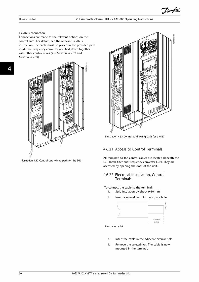
Fieldbus connectionConnections are made to the relevant options on thecontrol card. For details, see the relevant fieldbusinstruction. The cable must be placed in the provided pathinside the frequency converter and tied down togetherwith other control wires (see Illustration 4.32 andIllustration 4.33).
Illustration 4.32 Control card wiring path for the D13
Illustration 4.33 Control card wiring path for the E9
4.6.21 Access to Control Terminals
All terminals to the control cables are located beneath theLCP (both filter and frequency converter LCP). They areaccessed by opening the door of the unit.
4.6.22 Electrical Installation, ControlTerminals
To connect the cable to the terminal:1. Strip insulation by about 9-10 mm
2. Insert a screwdriver1) in the square hole.
130B
A15
0.10
9 - 10 mm
(0.37 in)
Illustration 4.34
3. Insert the cable in the adjacent circular hole.
4. Remove the screwdriver. The cable is nowmounted in the terminal.
How to Install VLT AutomationDrive LHD for AAF 006 Operating Instructions
50 MG37A102 - VLT® is a registered Danfoss trademark
44

130B
T312
.10
Illustration 4.35
To remove the cable from the terminal:1. Insert a screw driver1) in the square hole.
2. Pull out the cable.
130B
T311
.10
Illustration 4.36
1) Max. 0.4 x 2.5 mm
130B
T306
.10
Illustration 4.37
4.7 Connection Examples for Control ofMotor with External Signal Provider
NOTEThe following examples refer only to the frequencyconverter control card (right LCP), not the filter.
4.7.1 Start/Stop
Terminal 18 = 5-10 Terminal 18 Digital Input [8] StartTerminal 27 = 5-12 Terminal 27 Digital Input [0] Nooperation (Default coast inverse)Terminal 37 = Safe stop
12 13 18 37 130B
A15
5.12
322719 29 33 20
P 5-
12 [0
]
P 5-
10 [8
]
Start/Stop
+24V
Speed
Safe Stop
Start/Stop[18]
Illustration 4.38
4.7.2 Pulse Start/Stop
Terminal 18 = 5-10 Terminal 18 Digital Input [9] LatchedstartTerminal 27= 5-12 Terminal 27 Digital Input [6] Stop inverseTerminal 37 = Safe stop
How to Install VLT AutomationDrive LHD for AAF 006 Operating Instructions
MG37A102 - VLT® is a registered Danfoss trademark 51
4 4

12 13 18 37
130B
A15
6.12
322719 29 33 20
P 5
- 12
[6]
P 5
- 10[
9]
+24V
Speed
Start Stop inverse Safe Stop
Start (18)
Start (27)
Illustration 4.39
4.7.3 Speed Up/Down
Terminals 29/32 = Speed up/downTerminal 18 = 5-10 Terminal 18 Digital Input Start[9] (default)
Terminal 27 = 5-12 Terminal 27 Digital InputFreeze reference [19]
Terminal 29 = 5-13 Terminal 29 Digital InputSpeed up [21]
Terminal 32 = 5-14 Terminal 32 Digital InputSpeed down [22]
12
18
27
29
32
37
+24V
Par. 5-10
Par. 5-12
Par. 5-13
Par. 5-14
130B
A02
1.12
Illustration 4.40
4.7.4 Potentiometer Reference
Voltage reference via a potentiometerReference Source 1 = [1] Analog input 53 (default)
Terminal 53, Low Voltage = 0V
Terminal 53, High Voltage = 10V
Terminal 53, Low Ref./Feedback = 0 RPM
Terminal 53, High Ref./Feedback = 1500 RPM
Switch S201 = OFF (U)
130B
A15
4.11
555039 42 53 54Speed RPMP 6-15
1 kΩ
+10V
/30m
A
Ref. voltageP 6-11 10V
Illustration 4.41
How to Install VLT AutomationDrive LHD for AAF 006 Operating Instructions
52 MG37A102 - VLT® is a registered Danfoss trademark
44

4.8 Electrical Installation - Additional
4.8.1 Electrical Installation, Control Cables
1
DC bus Switch ModePower Supply
Motor
Analog Output
Interface
relay1
relay2
(PNP) = Source(NPN) = Sink
ON=TerminatedOFF=Open
Brakeresistor
130B
B450
.10
91 (L1)92 (L2)93 (L3)
PE
88 (-)89 (+)
50 (+10 V OUT)
53 (A IN)
54 (A IN)
55 (COM A IN)0/4-20 mA
12 (+24V OUT)
13 (+24V OUT)
37 (D IN)
18 (D IN)
20 (COM D IN)
10Vdc15mA 130/200mA
+ - + -
(U) 96(V) 97
(W) 98(PE) 99
(COM A OUT) 39
(A OUT) 42
(P RS-485) 68
(N RS-485) 69
(COM RS-485) 61
0V
5V
S801
0/4-20 mA
RS-485RS-485
03
+10Vdc-10Vdc -
+10Vdc
+10Vdc0/4-20 mA
-10Vdc -
240Vac, 2A
24Vdc
02
01
05
04
06240Vac, 2A
24V (NPN) 0V (PNP)
0V (PNP)24V (NPN)
19 (D IN)
24V (NPN) 0V (PNP)27
24V
0V
(D IN/OUT)
0V (PNP)24V (NPN)
(D IN/OUT)
0V
24V29
24V (NPN) 0V (PNP)
0V (PNP)24V (NPN)
33 (D IN)
32 (D IN)
12
ON
S201
ON2
1S202ON/I=0-20mAOFF/U=0-10V
95
400Vac, 2AP 5-00
21 O
N
S801
(R+) 82
(R-) 81
*
*
Illustration 4.42 Diagram showing all electrical terminals without options.1: Connection to filterTerminal 37 is the input to be used for Safe Stop. For instructions on Safe Stop installation please refer to the section Safe Stop Instal-lation in the frequency converter Design Guide. See also sections Safe Stop and Safe Stop Installation.
Very long control cables and analogue signals may in rarecases and depending on installation result in 50/60 Hzearth loops due to noise from mains supply cables.
If this occurs, it may be necessary to break the screen orinsert a 100 nF capacitor between screen and chassis.
The digital and analog inputs and outputs must beconnected separately to the control cards of the unit (bothfilter and drive, terminal 20, 55, 39) to avoid earth currentsfrom both groups to affect other groups. For example,switching on the digital input may disturb the analoginput signal.
How to Install VLT AutomationDrive LHD for AAF 006 Operating Instructions
MG37A102 - VLT® is a registered Danfoss trademark 53
4 4
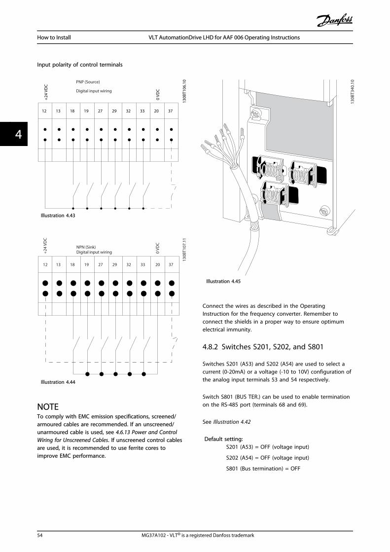
Input polarity of control terminals
12 13 18 19 27 29 32 33 20 37
+24
VDC
0 VD
C
130B
T106
.10PNP (Source)
Digital input wiring
Illustration 4.43
NPN (Sink)Digital input wiring
12 13 18 19 27 29 32 33 20 37
+24
VDC
0 VD
C
130B
T107
.11
Illustration 4.44
NOTETo comply with EMC emission specifications, screened/armoured cables are recommended. If an unscreened/unarmoured cable is used, see 4.6.13 Power and ControlWiring for Unscreened Cables. If unscreened control cablesare used, it is recommended to use ferrite cores toimprove EMC performance.
130B
T340
.10
Illustration 4.45
Connect the wires as described in the OperatingInstruction for the frequency converter. Remember toconnect the shields in a proper way to ensure optimumelectrical immunity.
4.8.2 Switches S201, S202, and S801
Switches S201 (A53) and S202 (A54) are used to select acurrent (0-20mA) or a voltage (-10 to 10V) configuration ofthe analog input terminals 53 and 54 respectively.
Switch S801 (BUS TER.) can be used to enable terminationon the RS-485 port (terminals 68 and 69).
See Illustration 4.42
Default setting:S201 (A53) = OFF (voltage input)
S202 (A54) = OFF (voltage input)
S801 (Bus termination) = OFF
How to Install VLT AutomationDrive LHD for AAF 006 Operating Instructions
54 MG37A102 - VLT® is a registered Danfoss trademark
44
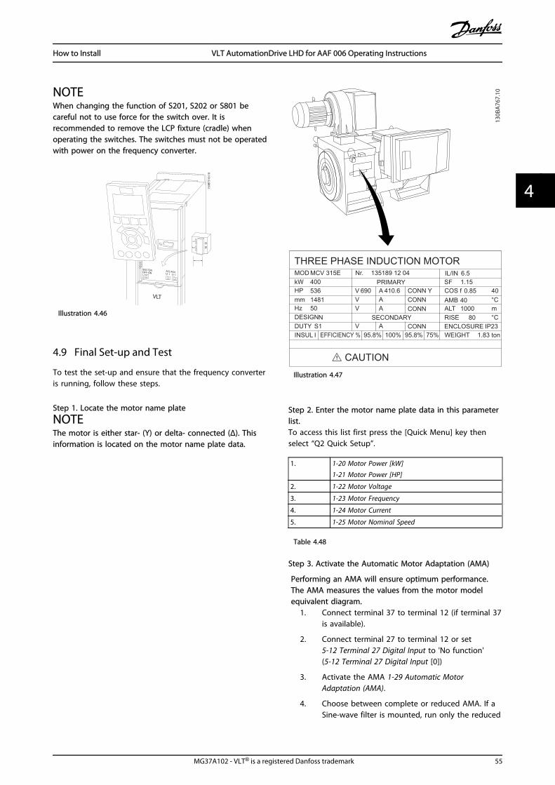
NOTEWhen changing the function of S201, S202 or S801 becareful not to use force for the switch over. It isrecommended to remove the LCP fixture (cradle) whenoperating the switches. The switches must not be operatedwith power on the frequency converter.
130B
T310
.10
12 N
O
VLT
BUS TER.OFF-ON
A53 A54U- I U- I
Illustration 4.46
4.9 Final Set-up and Test
To test the set-up and ensure that the frequency converteris running, follow these steps.
Step 1. Locate the motor name plate
NOTEThe motor is either star- (Y) or delta- connected (Δ). Thisinformation is located on the motor name plate data.
THREE PHASE INDUCTION MOTOR
kW 400MOD MCV 315E Nr. 135189 12 04
PRIMARY
SECONDARY
V 690 AV AV A
V A
410.6 CONN YCONNCONN
CONN ENCLOSURE
CAUTION
COS f
ALTRISE
m
SF 1.150.85
AMB 401000
80
°C
°CIP23
40
IL/IN 6.5
HP 536mm 1481HzDESIGN
50N
DUTYINSUL WEIGHT 1.83 tonEFFICIENCY % 95.8% 95.8% 75%100%
S1I
130B
A76
7.10
Illustration 4.47
Step 2. Enter the motor name plate data in this parameterlist.To access this list first press the [Quick Menu] key thenselect “Q2 Quick Setup”.
1. 1-20 Motor Power [kW]1-21 Motor Power [HP]
2. 1-22 Motor Voltage
3. 1-23 Motor Frequency
4. 1-24 Motor Current
5. 1-25 Motor Nominal Speed
Table 4.48
Step 3. Activate the Automatic Motor Adaptation (AMA)
Performing an AMA will ensure optimum performance.The AMA measures the values from the motor modelequivalent diagram.
1. Connect terminal 37 to terminal 12 (if terminal 37is available).
2. Connect terminal 27 to terminal 12 or set5-12 Terminal 27 Digital Input to 'No function'(5-12 Terminal 27 Digital Input [0])
3. Activate the AMA 1-29 Automatic MotorAdaptation (AMA).
4. Choose between complete or reduced AMA. If aSine-wave filter is mounted, run only the reduced
How to Install VLT AutomationDrive LHD for AAF 006 Operating Instructions
MG37A102 - VLT® is a registered Danfoss trademark 55
4 4

AMA, or remove the Sine-wave filter during theAMA procedure.
5. Press the [OK] key. The display shows “Press[Hand On] to start”.
6. Press the [Hand On] key. A progress bar indicatesif the AMA is in progress.
Stop the AMA during operation1. Press the [OFF] key - the frequency converter
enters into alarm mode and the display showsthat the AMA was terminated by the user.
Successful AMA1. The display shows “Press [OK] to finish AMA”.
2. Press the [OK] key to exit the AMA state.
Unsuccessful AMA1. The frequency converter enters into alarm mode.
A description of the alarm can be found in theWarnings and Alarms chapter.
2. "Report Value” in the [Alarm Log] shows the lastmeasuring sequence carried out by the AMA,before the frequency converter entered alarmmode. This number along with the description ofthe alarm will assist you in troubleshooting. If youcontact Danfoss for service, make sure to mentionnumber and alarm description.
NOTEUnsuccessful AMA is often caused by incorrectly registeredmotor name plate data or a too big difference betweenthe motor power size and the frequency converter powersize.
Step 4. Set speed limit and ramp time3-02 Minimum Reference
3-03 Maximum Reference
Set up the desired limits for speed and ramp time4-11 Motor Speed Low Limit [RPM] or 4-12 MotorSpeed Low Limit [Hz]
4-13 Motor Speed High Limit [RPM] or 4-14 MotorSpeed High Limit [Hz]
3-41 Ramp 1 Ramp up Time
3-42 Ramp 1 Ramp Down Time
4.10 Additional Connections
4.10.1 Mechanical Brake Control
In hoisting/lowering applications, it is necessary to be ableto control an electro-mechanical brake:
• Control the brake using any relay output ordigital output (terminal 27 or 29).
• Keep the output closed (voltage-free) as long asthe frequency converter is unable to ‘support’ the
motor, for example due to the load being tooheavy.
• Select Mechanical brake control [32] in parametergroup 5-4* for applications with an electro-mechanical brake.
• The brake is released when the motor currentexceeds the preset value in 2-20 Release BrakeCurrent.
• The brake is engaged when the output frequencyis less than the frequency set in 2-21 ActivateBrake Speed [RPM] or 2-22 Activate Brake Speed[Hz], and only if the frequency converter carriesout a stop command.
If the frequency converter is in alarm mode or in an over-voltage situation, the mechanical brake immediately cutsin.
4.10.2 Parallel Connection of Motors
The frequency converter can control several parallel-connected motors. The total current consumption of themotors must not exceed the rated output current IM,N forthe frequency converter.
How to Install VLT AutomationDrive LHD for AAF 006 Operating Instructions
56 MG37A102 - VLT® is a registered Danfoss trademark
44
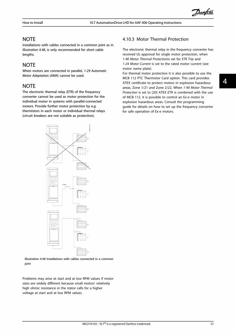
NOTEInstallations with cables connected in a common joint as inIllustration 4.48, is only recommended for short cablelengths.
NOTEWhen motors are connected in parallel, 1-29 AutomaticMotor Adaptation (AMA) cannot be used.
NOTEThe electronic thermal relay (ETR) of the frequencyconverter cannot be used as motor protection for theindividual motor in systems with parallel-connectedmotors. Provide further motor protection by e.g.thermistors in each motor or individual thermal relays(circuit breakers are not suitable as protection).
LC lter
130B
A17
0.10
Illustration 4.48 Installations with cables connected in a commonjoint
Problems may arise at start and at low RPM values if motorsizes are widely different because small motors' relativelyhigh ohmic resistance in the stator calls for a highervoltage at start and at low RPM values.
4.10.3 Motor Thermal Protection
The electronic thermal relay in the frequency converter hasreceived UL-approval for single motor protection, when 1-90 Motor Thermal Protectionis set for ETR Trip and1-24 Motor Current is set to the rated motor current (seemotor name plate).For thermal motor protection it is also possible to use theMCB 112 PTC Thermistor Card option. This card providesATEX certificate to protect motors in explosion hazardousareas, Zone 1/21 and Zone 2/22. When 1-90 Motor ThermalProtection is set to [20] ATEX ETR is combined with the useof MCB 112, it is possible to control an Ex-e motor inexplosion hazardous areas. Consult the programmingguide for details on how to set up the frequency converterfor safe operation of Ex-e motors.
How to Install VLT AutomationDrive LHD for AAF 006 Operating Instructions
MG37A102 - VLT® is a registered Danfoss trademark 57
4 4
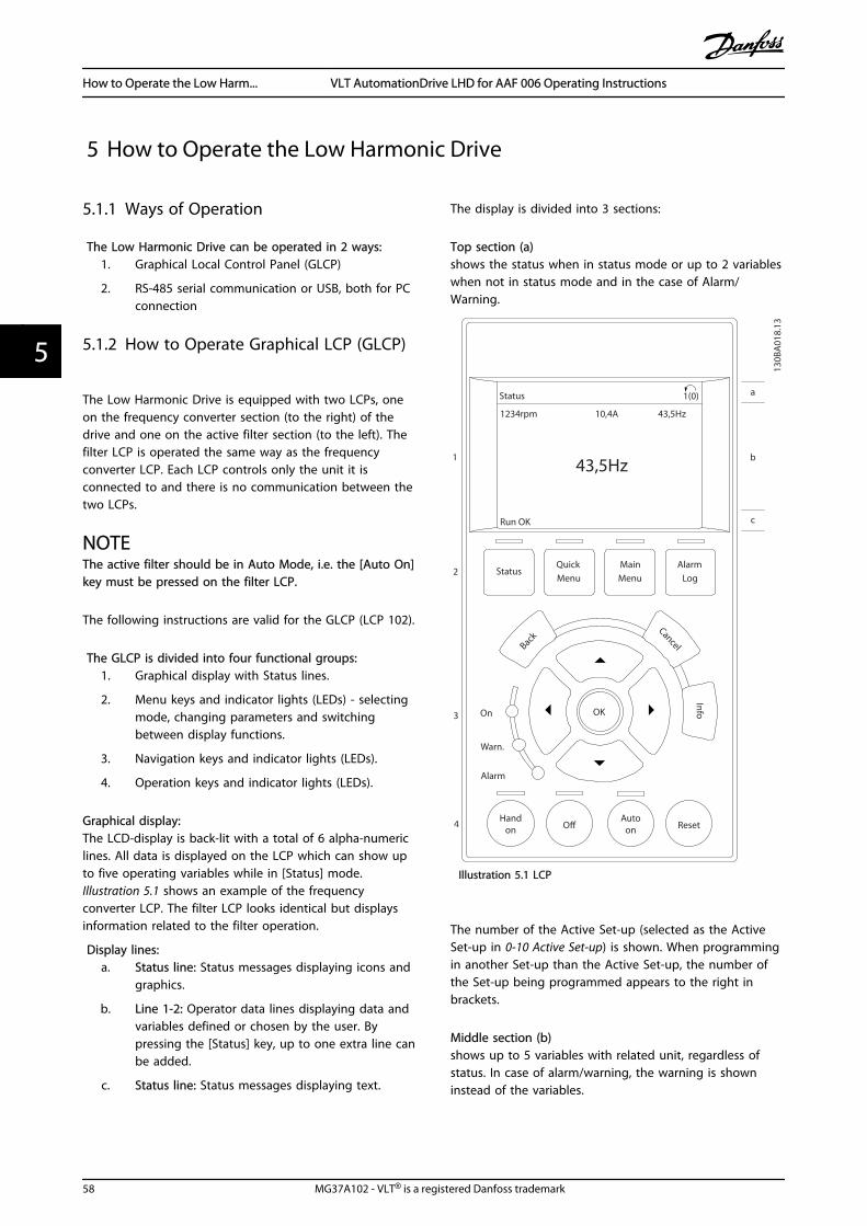
5 How to Operate the Low Harmonic Drive
5.1.1 Ways of Operation
The Low Harmonic Drive can be operated in 2 ways:1. Graphical Local Control Panel (GLCP)
2. RS-485 serial communication or USB, both for PCconnection
5.1.2 How to Operate Graphical LCP (GLCP)
The Low Harmonic Drive is equipped with two LCPs, oneon the frequency converter section (to the right) of thedrive and one on the active filter section (to the left). Thefilter LCP is operated the same way as the frequencyconverter LCP. Each LCP controls only the unit it isconnected to and there is no communication between thetwo LCPs.
NOTEThe active filter should be in Auto Mode, i.e. the [Auto On]key must be pressed on the filter LCP.
The following instructions are valid for the GLCP (LCP 102).
The GLCP is divided into four functional groups:1. Graphical display with Status lines.
2. Menu keys and indicator lights (LEDs) - selectingmode, changing parameters and switchingbetween display functions.
3. Navigation keys and indicator lights (LEDs).
4. Operation keys and indicator lights (LEDs).
Graphical display:The LCD-display is back-lit with a total of 6 alpha-numericlines. All data is displayed on the LCP which can show upto five operating variables while in [Status] mode.Illustration 5.1 shows an example of the frequencyconverter LCP. The filter LCP looks identical but displaysinformation related to the filter operation.
Display lines:a. Status line: Status messages displaying icons and
graphics.
b. Line 1-2: Operator data lines displaying data andvariables defined or chosen by the user. Bypressing the [Status] key, up to one extra line canbe added.
c. Status line: Status messages displaying text.
The display is divided into 3 sections:
Top section (a)shows the status when in status mode or up to 2 variableswhen not in status mode and in the case of Alarm/Warning.
Autoon Reset
Handon O
StatusQuickMenu
MainMenu
AlarmLog
Back
Cancel
InfoOK
Status 1(0)
1234rpm 10,4A 43,5Hz
Run OK
43,5Hz
On
Alarm
Warn.
130B
A01
8.13
1
2
3
4
b
a
c
Illustration 5.1 LCP
The number of the Active Set-up (selected as the ActiveSet-up in 0-10 Active Set-up) is shown. When programmingin another Set-up than the Active Set-up, the number ofthe Set-up being programmed appears to the right inbrackets.
Middle section (b)shows up to 5 variables with related unit, regardless ofstatus. In case of alarm/warning, the warning is showninstead of the variables.
How to Operate the Low Harm... VLT AutomationDrive LHD for AAF 006 Operating Instructions
58 MG37A102 - VLT® is a registered Danfoss trademark
55
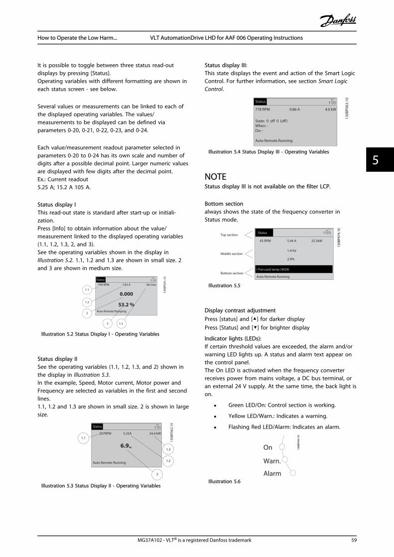
It is possible to toggle between three status read-outdisplays by pressing [Status].Operating variables with different formatting are shown ineach status screen - see below.
Several values or measurements can be linked to each ofthe displayed operating variables. The values/measurements to be displayed can be defined viaparameters 0-20, 0-21, 0-22, 0-23, and 0-24.
Each value/measurement readout parameter selected inparameters 0-20 to 0-24 has its own scale and number ofdigits after a possible decimal point. Larger numeric valuesare displayed with few digits after the decimal point.Ex.: Current readout5.25 A; 15.2 A 105 A.
Status display IThis read-out state is standard after start-up or initiali-zation.Press [Info] to obtain information about the value/measurement linked to the displayed operating variables(1.1, 1.2, 1.3, 2, and 3).See the operating variables shown in the display inIllustration 5.2. 1.1, 1.2 and 1.3 are shown in small size. 2and 3 are shown in medium size.
1.1
2
3 1.3
1.2
130B
P041
.10
799 RPM
Auto Remote Ramping
1 (1)36.4 kw7.83 A
0.000
53.2 %
Status
Illustration 5.2 Status Display I - Operating Variables
Status display IISee the operating variables (1.1, 1.2, 1.3, and 2) shown inthe display in Illustration 5.3.In the example, Speed, Motor current, Motor power andFrequency are selected as variables in the first and secondlines.1.1, 1.2 and 1.3 are shown in small size. 2 is shown in largesize.
1.1
1.2
2
1.3
130B
P062
.10
207RPM
Auto Remote Running
1 (1)
24.4 kW5.25A
6.9Hz
Status
Illustration 5.3 Status Display II - Operating Variables
Status display III:This state displays the event and action of the Smart LogicControl. For further information, see section Smart LogicControl.
130B
P063
.10
778 RPM
Auto Remote Running
1 (1)
4.0 kW0.86 A
State: 0 o 0 (o)When: - Do: -
Status
Illustration 5.4 Status Display III - Operating Variables
NOTEStatus display III is not available on the filter LCP.
Bottom sectionalways shows the state of the frequency converter inStatus mode.
Top section
Middle section
Bottom section
Status
43 RPM
1.4 Hz
Auto Remote Running
! Pwr.card temp (W29)
2.9%
5.44 A 25.3kW
1(1)
130B
P074
.10
!
Illustration 5.5
Display contrast adjustmentPress [status] and [] for darker displayPress [Status] and [] for brighter display
Indicator lights (LEDs):If certain threshold values are exceeded, the alarm and/orwarning LED lights up. A status and alarm text appear onthe control panel.The On LED is activated when the frequency converterreceives power from mains voltage, a DC bus terminal, oran external 24 V supply. At the same time, the back light ison.
• Green LED/On: Control section is working.
• Yellow LED/Warn.: Indicates a warning.
• Flashing Red LED/Alarm: Indicates an alarm.
On
Warn.
Alarm
130B
P044
.10
Illustration 5.6
How to Operate the Low Harm... VLT AutomationDrive LHD for AAF 006 Operating Instructions
MG37A102 - VLT® is a registered Danfoss trademark 59
5 5

GLCP keysMenu keysThe menu keys are divided into functions. The keys belowthe display and indicator lamps are used for parameter set-up, including choice of display indication during normaloperation.
130B
P045
.10
Status QuickMenu
MainMenu
AlarmLog
Illustration 5.7
[Status]Indicates the status of the frequency converter (and/or themotor) or the filter respectively. On the drive LCP, 3different readouts can be chosen by pressing the [Status]key:5 line readouts, 4 line readouts or Smart Logic Control.Smart Logic Control is not available for the filter.Use [Status] for selecting the mode of display or forchanging back to Display mode from either the QuickMenu mode, the Main Menu mode or Alarm mode. Alsouse the [Status] key to toggle single or double read-outmode.
[Quick Menu]Allows quick set-up of the frequency converter or the filter.The most common functions can be programmed here.
The [Quick Menu] consists of:- Q1: My Personal Menu
- Q2: Quick Setup
- Q5: Changes Made
- Q6: Loggings
Since the active filter is an integrated part of the LowHarmonic Drive only a minimum of programming isnecessary. The filter LCP is mainly used to displayinformation about filter operation such as THD of voltageor current, corrected current, injected current or Cos ϕ andTrue Power Factor.
The Quick Menu parameters can be accessed immediatelyunless a password has been created via parameters 0-60,0-61, 0-65 or 0-66.It is possible to switch directly between Quick Menu modeand Main Menu mode.
[Main Menu]is used for programming all parameters.The Main Menu parameters can be accessed immediatelyunless a password has been created via parameters 0-60,0-61, 0-65 or 0-66.It is possible to switch directly between Main Menu modeand Quick Menu mode.Parameter shortcut can be carried out by pressing downthe [Main Menu] key for 3 seconds. The parameter shortcutallows direct access to any parameter.
[Alarm Log]displays an Alarm list of the five latest alarms (numberedA1-A5). To obtain additional details about an alarm, usethe arrow keys to manoeuvre to the alarm number andpress [OK]. Information is displayed about the condition ofthe frequency converter or filter before it enters the alarmmode.
[Back]reverts to the previous step or layer in the navigationstructure.
Back
Illustration 5.8
[Cancel]last change or command will be cancelled as long as thedisplay has not been changed.
Cancel
Illustration 5.9
[Info]displays information about a command, parameter, orfunction in any display window. [Info] provides detailedinformation when needed.Exit Info mode by pressing either [Info], [Back], or [Cancel].
Info
Illustration 5.10
Navigation keysThe four navigation kays are used to navigate between thedifferent choices available in [Quick Menu], [Main Menu]and [Alarm Log]. Use the keys to move the cursor.
[OK]is used for choosing a parameter marked by the cursorand for enabling the change of a parameter.
How to Operate the Low Harm... VLT AutomationDrive LHD for AAF 006 Operating Instructions
60 MG37A102 - VLT® is a registered Danfoss trademark
55
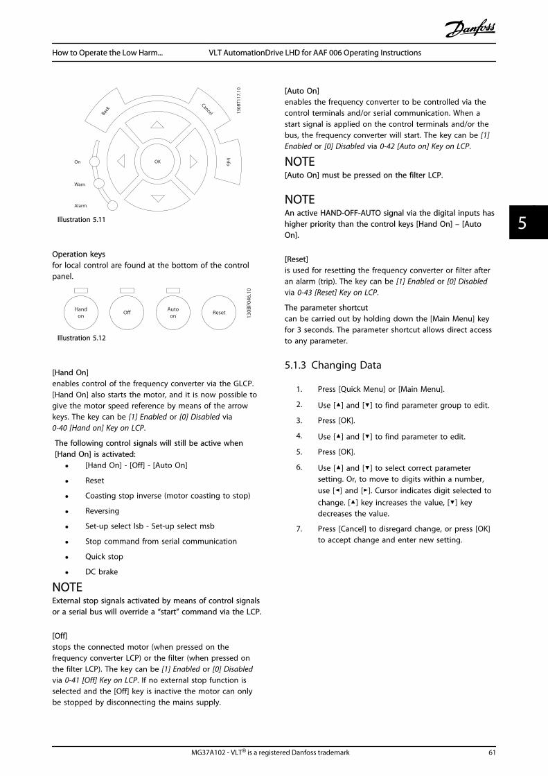
130B
T117
.10
OK
Back
Info
Warn
Alarm
On
Cancel
Illustration 5.11
Operation keysfor local control are found at the bottom of the controlpanel.
130B
P046
.10
Handon O Auto
on Reset
Illustration 5.12
[Hand On]enables control of the frequency converter via the GLCP.[Hand On] also starts the motor, and it is now possible togive the motor speed reference by means of the arrowkeys. The key can be [1] Enabled or [0] Disabled via0-40 [Hand on] Key on LCP.
The following control signals will still be active when[Hand On] is activated:
• [Hand On] - [Off] - [Auto On]
• Reset
• Coasting stop inverse (motor coasting to stop)
• Reversing
• Set-up select lsb - Set-up select msb
• Stop command from serial communication
• Quick stop
• DC brake
NOTEExternal stop signals activated by means of control signalsor a serial bus will override a “start” command via the LCP.
[Off]stops the connected motor (when pressed on thefrequency converter LCP) or the filter (when pressed onthe filter LCP). The key can be [1] Enabled or [0] Disabledvia 0-41 [Off] Key on LCP. If no external stop function isselected and the [Off] key is inactive the motor can onlybe stopped by disconnecting the mains supply.
[Auto On]enables the frequency converter to be controlled via thecontrol terminals and/or serial communication. When astart signal is applied on the control terminals and/or thebus, the frequency converter will start. The key can be [1]Enabled or [0] Disabled via 0-42 [Auto on] Key on LCP.
NOTE[Auto On] must be pressed on the filter LCP.
NOTEAn active HAND-OFF-AUTO signal via the digital inputs hashigher priority than the control keys [Hand On] – [AutoOn].
[Reset]is used for resetting the frequency converter or filter afteran alarm (trip). The key can be [1] Enabled or [0] Disabledvia 0-43 [Reset] Key on LCP.
The parameter shortcutcan be carried out by holding down the [Main Menu] keyfor 3 seconds. The parameter shortcut allows direct accessto any parameter.
5.1.3 Changing Data
1. Press [Quick Menu] or [Main Menu].
2. Use [] and [] to find parameter group to edit.
3. Press [OK].
4. Use [] and [] to find parameter to edit.
5. Press [OK].
6. Use [] and [] to select correct parametersetting. Or, to move to digits within a number,use [] and []. Cursor indicates digit selected tochange. [] key increases the value, [] keydecreases the value.
7. Press [Cancel] to disregard change, or press [OK]to accept change and enter new setting.
How to Operate the Low Harm... VLT AutomationDrive LHD for AAF 006 Operating Instructions
MG37A102 - VLT® is a registered Danfoss trademark 61
5 5
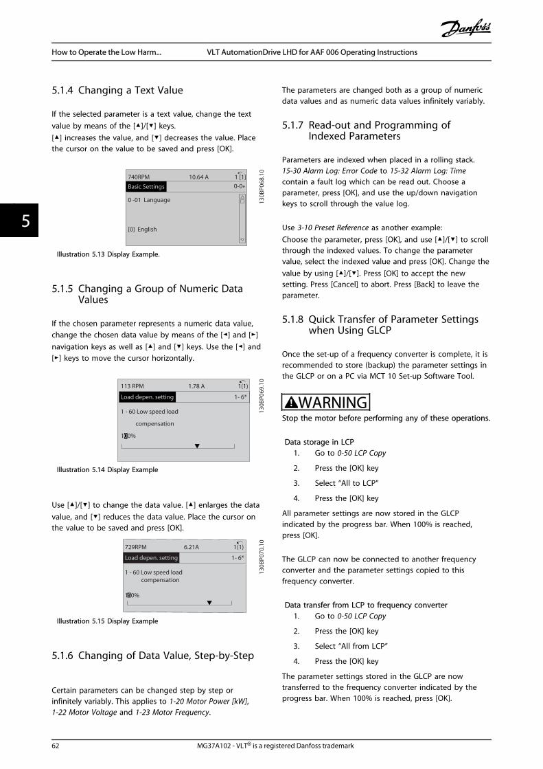
5.1.4 Changing a Text Value
If the selected parameter is a text value, change the textvalue by means of the []/[] keys.[] increases the value, and [] decreases the value. Placethe cursor on the value to be saved and press [OK].
130B
P068
.10
740RPM
0 -01 Language
[0] English
10.64 A 1 [1]0-0*Basic Settings
Illustration 5.13 Display Example.
5.1.5 Changing a Group of Numeric DataValues
If the chosen parameter represents a numeric data value,change the chosen data value by means of the [] and []navigation keys as well as [] and [] keys. Use the [] and[] keys to move the cursor horizontally.
130B
P069
.10
1- 6*
113 RPM 1.78 A 1(1)
Load depen. setting
1 - 60 Low speed load
compensation
100%
Illustration 5.14 Display Example
Use []/[] to change the data value. [] enlarges the datavalue, and [] reduces the data value. Place the cursor onthe value to be saved and press [OK].
130B
P070
.10
1 - 60 Low speed load compensation
1 0%
Load depen. setting 1- 6*
729RPM 6.21A 1(1)
6
Illustration 5.15 Display Example
5.1.6 Changing of Data Value, Step-by-Step
Certain parameters can be changed step by step orinfinitely variably. This applies to 1-20 Motor Power [kW], 1-22 Motor Voltage and 1-23 Motor Frequency.
The parameters are changed both as a group of numericdata values and as numeric data values infinitely variably.
5.1.7 Read-out and Programming ofIndexed Parameters
Parameters are indexed when placed in a rolling stack.15-30 Alarm Log: Error Code to 15-32 Alarm Log: Timecontain a fault log which can be read out. Choose aparameter, press [OK], and use the up/down navigationkeys to scroll through the value log.
Use 3-10 Preset Reference as another example:Choose the parameter, press [OK], and use []/[] to scrollthrough the indexed values. To change the parametervalue, select the indexed value and press [OK]. Change thevalue by using []/[]. Press [OK] to accept the newsetting. Press [Cancel] to abort. Press [Back] to leave theparameter.
5.1.8 Quick Transfer of Parameter Settingswhen Using GLCP
Once the set-up of a frequency converter is complete, it isrecommended to store (backup) the parameter settings inthe GLCP or on a PC via MCT 10 Set-up Software Tool.
WARNINGStop the motor before performing any of these operations.
Data storage in LCP1. Go to 0-50 LCP Copy
2. Press the [OK] key
3. Select “All to LCP”
4. Press the [OK] key
All parameter settings are now stored in the GLCPindicated by the progress bar. When 100% is reached,press [OK].
The GLCP can now be connected to another frequencyconverter and the parameter settings copied to thisfrequency converter.
Data transfer from LCP to frequency converter1. Go to 0-50 LCP Copy
2. Press the [OK] key
3. Select “All from LCP”
4. Press the [OK] key
The parameter settings stored in the GLCP are nowtransferred to the frequency converter indicated by theprogress bar. When 100% is reached, press [OK].
How to Operate the Low Harm... VLT AutomationDrive LHD for AAF 006 Operating Instructions
62 MG37A102 - VLT® is a registered Danfoss trademark
55

5.1.9 Initialisation to Default Settings
There are two ways to initialise the frequency converter todefault: Recommended initialisation and manual initiali-sation.Be aware that they have different impact according to thebelow description.
Recommended initialisation (via 14-22 Operation Mode)1. Select 14-22 Operation Mode
2. Press [OK]
3. Select Initialisation (for NLCP select “2”)
4. Press [OK]
5. Remove power to unit and wait for display toturn off.
6. Reconnect power and the frequency converter isreset.
NOTEFirst start-up takes a few more seconds.
7. Press [Reset]
14-22 Operation Mode initialises all except:14-50 RFI Filter8-30 Protocol8-31 Address8-32 Baud Rate8-35 Minimum Response Delay8-36 Max Response Delay8-37 Maximum Inter-Char Delay15-00 Operating Hours to 15-05 Over Volt's15-20 Historic Log: Event to 15-22 Historic Log: Time15-30 Alarm Log: Error Code to 15-32 Alarm Log: Time
NOTEParameters selected in 0-25 My Personal Menu, will staypresent, with default factory setting.
Manual initialisation
NOTEWhen carrying out manual initialisation, serial communi-cation, RFI filter settings and fault log settings are reset.Removes parameters selected in 0-25 My Personal Menu.
1. Disconnect from mains and wait until thedisplay turns off.
2a. Press [Status] - [Main Menu] - [OK] at thesame time while power up for Graphical LCP(GLCP)
2b. Press [Menu] while power up for LCP 101,Numerical Display
3. Release the keys after 5 sec.
4. The frequency converter is now programmedaccording to default settings
This parameter initialises all except:15-00 Operating Hours15-03 Power Up's15-04 Over Temp's15-05 Over Volt's
5.1.10 RS-485 Bus Connection
Both filter portion and frequency converter can beconnected to a controller (or master) together with otherloads using the RS-485 standard interface. Terminal 68 isconnected to the P signal (TX+, RX+), while terminal 69 isconnected to the N signal (TX-,RX-).
Always use parallel connections for the Low HarmonicDrive to ensure that both filter and drive part is connected.
130B
A06
0.11
68 69 68 69 68 69
RS 485
RS 232USB
+
-
Illustration 5.16 Connection Example
To avoid potential equalizing currents in the screen, earththe cable screen via terminal 61, which is connected to theframe via an RC-link.
Bus terminationThe RS-485 bus must be terminated by a resistor networkat both ends. If the frequency converter is the first or thelast device in the RS-485 loop, set the switch S801 on thecontrol card for ON.For more information, see the paragraph Switches S201,S202, and S801.
5.1.11 How to Connect a PC to theFrequency Converter
To control or program the frequency converter (and thefilter part) from a PC, install the PC-based ConfigurationTool MCT 10.The PC is connected via a standard (host/device) USB cableto both devices, or via the RS-485 interface as shown inthe VLT HVAC Drive Design Guide, MG11BXYY, chapter Howto Install > Installation of misc. connections.
How to Operate the Low Harm... VLT AutomationDrive LHD for AAF 006 Operating Instructions
MG37A102 - VLT® is a registered Danfoss trademark 63
5 5

NOTEThe USB connection is galvanically isolated from thesupply voltage (PELV) and other high-voltage terminals.The USB connection is connected to protection earth onthe frequency converter. Use only an isolated laptop as PCconnection to the USB connector on the frequencyconverter.
130B
T308
.11
Illustration 5.17 For control cable connections, see 4.8.1 Electrical Installation, Control Cables .
5.1.12 PC software tools
PC-based Configuration Tool MCT 10The Low Harmonic Drive is equipped with two serialcommunication ports. Danfoss provides a PC tool forcommunication between PC and frequency converter, PC-based Configuration Tool MCT 10. Check for detailedinformation on this tool.
MCT 10 set-up softwareMCT 10 has been designed as an easy to use interactivetool for setting parameters in our frequency converters.The software can be downloaded from the Danfossinternet site http://www.Danfoss.com/BusinessAreas/Drives-Solutions/Softwaredownload/DDPC+Software+Program.htm.The MCT 10 set-up software will be useful for:
• Planning a communication network off-line. MCT10 contains a complete frequency converterdatabase
• Commissioning frequency converters on line
• Saving settings for all frequency converters
• Replacing a frequency converter in a network
• Simple and accurate documentation of frequencyconverter settings after commissioning.
• Expanding an existing network
• Future developed frequency converters will besupported
MCT 10 set-up software supports Profibus DP-V1 via aMaster class 2 connection. It makes it possible to on lineread/write parameters in a frequency converter via theProfibus network. This will eliminate the need for an extracommunication network.
Save frequency converter settings:
1. Connect a PC to the unit via USB com port.(NOTE: Use a PC, which is isolated from themains, in conjunction with the USB port. Failureto do so may damage equipment.)
2. Open MCT 10 Set-up Software
3. Choose “Read from drive”
4. Choose “Save as”
All parameters are now stored in the PC.
Load frequency converter settings:
1. Connect a PC to the frequency converter via USBcom port
2. Open MCT 10 Set-up software
3. Choose “Open”– stored files will be shown
4. Open the appropriate file
5. Choose “Write to drive”
All parameter settings are now transferred to thefrequency converter.
A separate manual for MCT 10 Set-up Software is available:MG10RXYY.
The MCT 10 Set-up software modulesThe following modules are included in the softwarepackage:
MCT Set-up 10 SoftwareSetting parametersCopy to and from frequency convertersDocumentation and print out of parametersettings incl. diagrams
Ext. user interface
Preventive Maintenance ScheduleClock settingsTimed Action ProgrammingSmart Logic Controller Set-up
Table 5.1
Ordering number:Order the CD containing MCT 10 Set-up Software usingcode number 130B1000.
MCT 10 can also be downloaded from the DanfossInternet: www.danfoss.com, Business Area: Motion Controls.
How to Operate the Low Harm... VLT AutomationDrive LHD for AAF 006 Operating Instructions
64 MG37A102 - VLT® is a registered Danfoss trademark
55
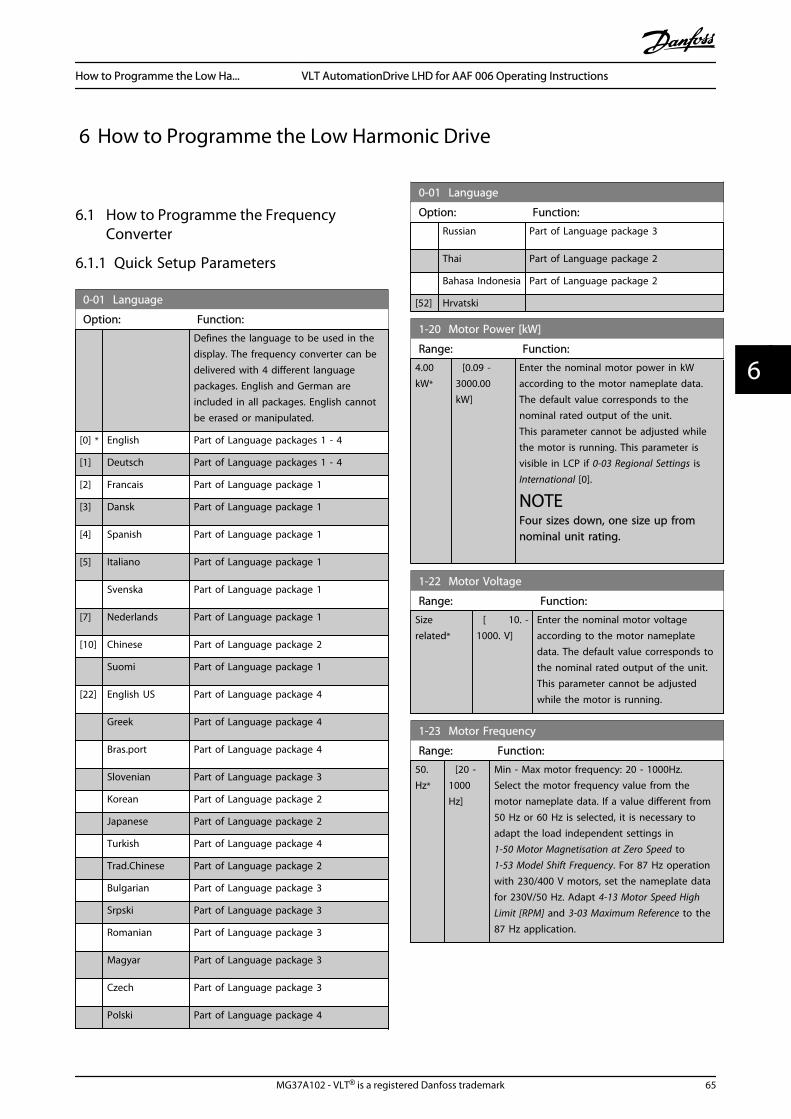
6 How to Programme the Low Harmonic Drive
6.1 How to Programme the FrequencyConverter
6.1.1 Quick Setup Parameters
0-01 Language
Option: Function:
Defines the language to be used in thedisplay. The frequency converter can bedelivered with 4 different languagepackages. English and German areincluded in all packages. English cannotbe erased or manipulated.
[0] * English Part of Language packages 1 - 4
[1] Deutsch Part of Language packages 1 - 4
[2] Francais Part of Language package 1
[3] Dansk Part of Language package 1
[4] Spanish Part of Language package 1
[5] Italiano Part of Language package 1
Svenska Part of Language package 1
[7] Nederlands Part of Language package 1
[10] Chinese Part of Language package 2
Suomi Part of Language package 1
[22] English US Part of Language package 4
Greek Part of Language package 4
Bras.port Part of Language package 4
Slovenian Part of Language package 3
Korean Part of Language package 2
Japanese Part of Language package 2
Turkish Part of Language package 4
Trad.Chinese Part of Language package 2
Bulgarian Part of Language package 3
Srpski Part of Language package 3
Romanian Part of Language package 3
Magyar Part of Language package 3
Czech Part of Language package 3
Polski Part of Language package 4
0-01 Language
Option: Function:
Russian Part of Language package 3
Thai Part of Language package 2
Bahasa Indonesia Part of Language package 2
[52] Hrvatski
1-20 Motor Power [kW]
Range: Function:
4.00kW*
[0.09 -3000.00kW]
Enter the nominal motor power in kWaccording to the motor nameplate data.The default value corresponds to thenominal rated output of the unit.This parameter cannot be adjusted whilethe motor is running. This parameter isvisible in LCP if 0-03 Regional Settings isInternational [0].
NOTEFour sizes down, one size up fromnominal unit rating.
1-22 Motor Voltage
Range: Function:
Sizerelated*
[ 10. -1000. V]
Enter the nominal motor voltageaccording to the motor nameplatedata. The default value corresponds tothe nominal rated output of the unit.This parameter cannot be adjustedwhile the motor is running.
1-23 Motor Frequency
Range: Function:
50.Hz*
[20 -1000Hz]
Min - Max motor frequency: 20 - 1000Hz.Select the motor frequency value from themotor nameplate data. If a value different from50 Hz or 60 Hz is selected, it is necessary toadapt the load independent settings in1-50 Motor Magnetisation at Zero Speed to1-53 Model Shift Frequency. For 87 Hz operationwith 230/400 V motors, set the nameplate datafor 230V/50 Hz. Adapt 4-13 Motor Speed HighLimit [RPM] and 3-03 Maximum Reference to the87 Hz application.
How to Programme the Low Ha... VLT AutomationDrive LHD for AAF 006 Operating Instructions
MG37A102 - VLT® is a registered Danfoss trademark 65
6 6

1-24 Motor Current
Range: Function:
Sizerelated*
[ 0.10 -10000.00 A]
Enter the nominal motor currentvalue from the motor nameplatedata. This data is used forcalculating motor torque, motorthermal protection etc.
NOTEThis parameter cannot be changed while the motor isrunning.
1-25 Motor Nominal Speed
Range: Function:
Size related* [100 - 60000RPM]
Enter the nominal motor speedvalue from the motor nameplatedata. This data is used forcalculating automatic motorcompensations.
NOTEThis parameter cannot be changed while the motor isrunning.
5-12 Terminal 27 Digital Input
Option: Function:
Select the function from the available digital inputrange.
No operation [0]
Reset [1]
Coast inverse [2]
Coast and reset inverse [3]
Quick stop inverse [4]
DC-brake inverse [5]
Stop inverse [6]
Start [8]
Latched start [9]
Reversing [10]
Start reversing [11]
Enable start forward [12]
Enable start reverse [13]
Jog [14]
Preset ref bit 0 [16]
Preset ref bit 1 [17]
Preset ref bit 2 [18]
Freeze reference [19]
Freeze output [20]
Speed up [21]
Speed down [22]
Set-up select bit 0 [23]
Set-up select bit 1 [24]
Catch up [28]
5-12 Terminal 27 Digital Input
Option: Function:Slow down [29]
Pulse input [32]
Ramp bit 0 [34]
Ramp bit 1 [35]
Mains failure inverse [36]
DigiPot Increase [55]
DigiPot Decrease [56]
DigiPot Clear [57]
Reset Counter A [62]
Reset Counter B [65]
Table 6.1
1-29 Automatic Motor Adaptation (AMA)
Option: Function:
The AMA function optimizes dynamic motorperformance by automatically optimizing theadvanced motor parameters (parameters 1-30to 1-35) at motor standstill.Activate the AMA function by pressing [Handon] after selecting [1] or [2]. See also thesection Automatic Motor Adaptation. After anormal sequence, the display will read: "Press[OK] to finish AMA". After pressing the [OK]key the frequency converter is ready foroperation.This parameter cannot be adjusted while themotor is running.
[0] * OFF
[1] EnablecompleteAMA
Performs AMA of the stator resistance RS, the
rotor resistance Rr, the stator leakage
reactance X1, the rotor leakage reactance X2
and the main reactance Xh.
FC 301: The complete AMA does not includeXh measurement for FC 301. Instead, the Xh
value is determined from the motor database.Par. 1-35 may be adjusted to obtain optimalstart performance.
[2] EnablereducedAMA
Performs a reduced AMA of the statorresistance Rs in the system only. Select this
option if an LC filter is used between the driveand the motor.
Note:
• For the best adaptation of the frequencyconverter, run AMA on a cold motor.
• AMA cannot be performed while the motor isrunning.
• AMA cannot be performed on permanent magnetmotors.
How to Programme the Low Ha... VLT AutomationDrive LHD for AAF 006 Operating Instructions
66 MG37A102 - VLT® is a registered Danfoss trademark
66
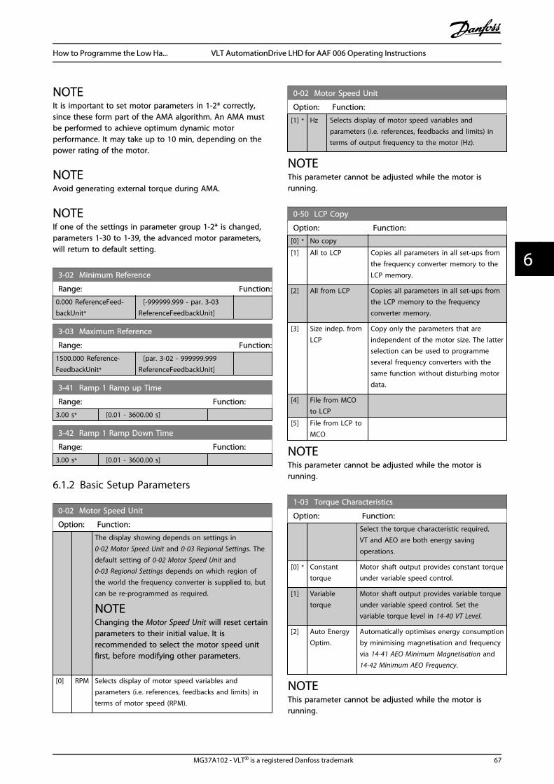
NOTEIt is important to set motor parameters in 1-2* correctly,since these form part of the AMA algorithm. An AMA mustbe performed to achieve optimum dynamic motorperformance. It may take up to 10 min, depending on thepower rating of the motor.
NOTEAvoid generating external torque during AMA.
NOTEIf one of the settings in parameter group 1-2* is changed,parameters 1-30 to 1-39, the advanced motor parameters,will return to default setting.
3-02 Minimum Reference
Range: Function:
0.000 ReferenceFeed-backUnit*
[-999999.999 - par. 3-03ReferenceFeedbackUnit]
3-03 Maximum Reference
Range: Function:
1500.000 Reference-FeedbackUnit*
[par. 3-02 - 999999.999ReferenceFeedbackUnit]
3-41 Ramp 1 Ramp up Time
Range: Function:
3.00 s* [0.01 - 3600.00 s]
3-42 Ramp 1 Ramp Down Time
Range: Function:
3.00 s* [0.01 - 3600.00 s]
6.1.2 Basic Setup Parameters
0-02 Motor Speed Unit
Option: Function:
The display showing depends on settings in 0-02 Motor Speed Unit and 0-03 Regional Settings. Thedefault setting of 0-02 Motor Speed Unit and0-03 Regional Settings depends on which region ofthe world the frequency converter is supplied to, butcan be re-programmed as required.
NOTEChanging the Motor Speed Unit will reset certainparameters to their initial value. It isrecommended to select the motor speed unitfirst, before modifying other parameters.
[0] RPM Selects display of motor speed variables andparameters (i.e. references, feedbacks and limits) interms of motor speed (RPM).
0-02 Motor Speed Unit
Option: Function:
[1] * Hz Selects display of motor speed variables andparameters (i.e. references, feedbacks and limits) interms of output frequency to the motor (Hz).
NOTEThis parameter cannot be adjusted while the motor isrunning.
0-50 LCP Copy
Option: Function:
[0] * No copy
[1] All to LCP Copies all parameters in all set-ups fromthe frequency converter memory to theLCP memory.
[2] All from LCP Copies all parameters in all set-ups fromthe LCP memory to the frequencyconverter memory.
[3] Size indep. fromLCP
Copy only the parameters that areindependent of the motor size. The latterselection can be used to programmeseveral frequency converters with thesame function without disturbing motordata.
[4] File from MCOto LCP
[5] File from LCP toMCO
NOTEThis parameter cannot be adjusted while the motor isrunning.
1-03 Torque Characteristics
Option: Function:
Select the torque characteristic required.VT and AEO are both energy savingoperations.
[0] * Constanttorque
Motor shaft output provides constant torqueunder variable speed control.
[1] Variabletorque
Motor shaft output provides variable torqueunder variable speed control. Set thevariable torque level in 14-40 VT Level.
[2] Auto EnergyOptim.
Automatically optimises energy consumptionby minimising magnetisation and frequencyvia 14-41 AEO Minimum Magnetisation and14-42 Minimum AEO Frequency.
NOTEThis parameter cannot be adjusted while the motor isrunning.
How to Programme the Low Ha... VLT AutomationDrive LHD for AAF 006 Operating Instructions
MG37A102 - VLT® is a registered Danfoss trademark 67
6 6
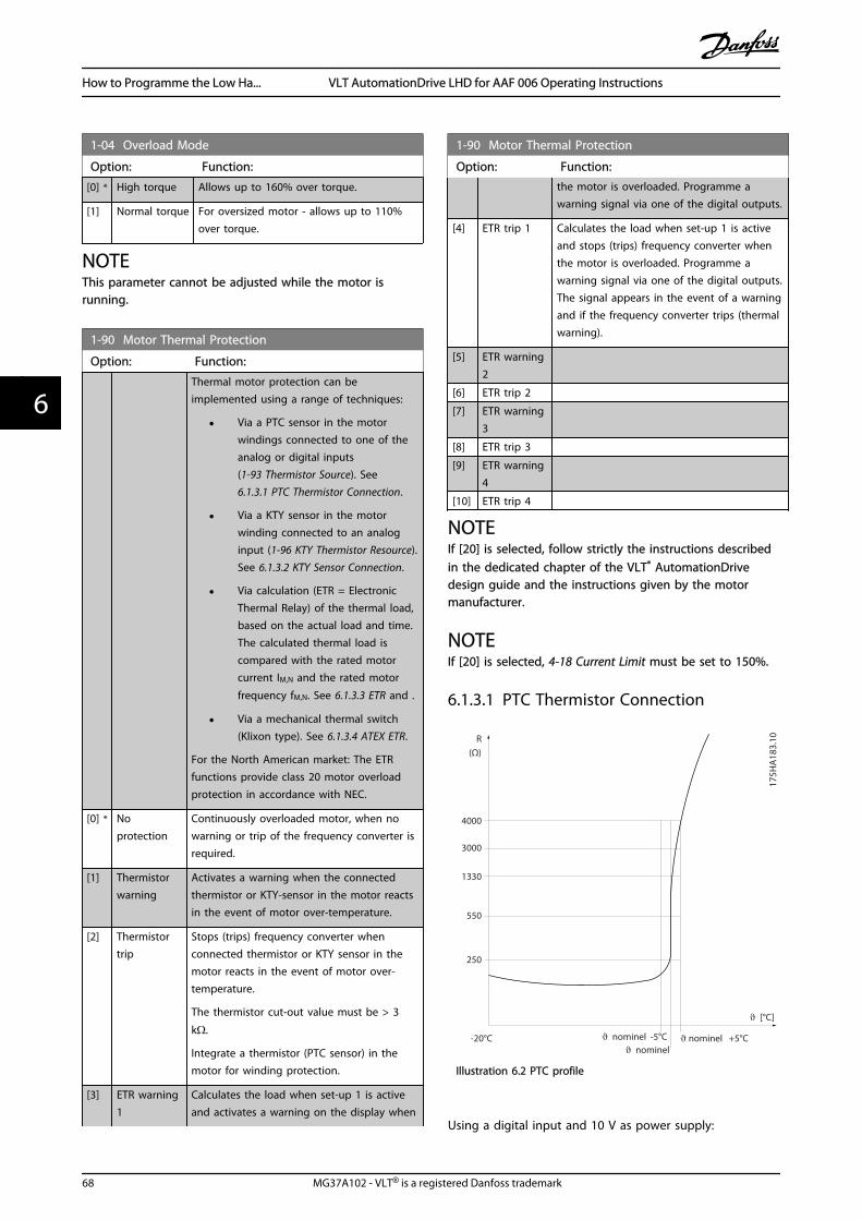
1-04 Overload Mode
Option: Function:
[0] * High torque Allows up to 160% over torque.
[1] Normal torque For oversized motor - allows up to 110%over torque.
NOTEThis parameter cannot be adjusted while the motor isrunning.
1-90 Motor Thermal Protection
Option: Function:
Thermal motor protection can beimplemented using a range of techniques:
• Via a PTC sensor in the motorwindings connected to one of theanalog or digital inputs(1-93 Thermistor Source). See 6.1.3.1 PTC Thermistor Connection.
• Via a KTY sensor in the motorwinding connected to an analoginput (1-96 KTY Thermistor Resource).See 6.1.3.2 KTY Sensor Connection.
• Via calculation (ETR = ElectronicThermal Relay) of the thermal load,based on the actual load and time.The calculated thermal load iscompared with the rated motorcurrent IM,N and the rated motor
frequency fM,N. See 6.1.3.3 ETR and .
• Via a mechanical thermal switch(Klixon type). See 6.1.3.4 ATEX ETR.
For the North American market: The ETRfunctions provide class 20 motor overloadprotection in accordance with NEC.
[0] * Noprotection
Continuously overloaded motor, when nowarning or trip of the frequency converter isrequired.
[1] Thermistorwarning
Activates a warning when the connectedthermistor or KTY-sensor in the motor reactsin the event of motor over-temperature.
[2] Thermistortrip
Stops (trips) frequency converter whenconnected thermistor or KTY sensor in themotor reacts in the event of motor over-temperature.
The thermistor cut-out value must be > 3
kΩ.
Integrate a thermistor (PTC sensor) in themotor for winding protection.
[3] ETR warning1
Calculates the load when set-up 1 is activeand activates a warning on the display when
1-90 Motor Thermal Protection
Option: Function:the motor is overloaded. Programme awarning signal via one of the digital outputs.
[4] ETR trip 1 Calculates the load when set-up 1 is activeand stops (trips) frequency converter whenthe motor is overloaded. Programme awarning signal via one of the digital outputs.The signal appears in the event of a warningand if the frequency converter trips (thermalwarning).
[5] ETR warning2
[6] ETR trip 2
[7] ETR warning3
[8] ETR trip 3
[9] ETR warning4
[10] ETR trip 4
NOTEIf [20] is selected, follow strictly the instructions describedin the dedicated chapter of the VLT® AutomationDrivedesign guide and the instructions given by the motormanufacturer.
NOTEIf [20] is selected, 4-18 Current Limit must be set to 150%.
6.1.3.1 PTC Thermistor Connection
1330
550
250
-20°C
175H
A18
3.10
4000
3000
R(Ω)
nominel nominel -5°C nominel +5°C
[°C]
Illustration 6.2 PTC profile
Using a digital input and 10 V as power supply:
How to Programme the Low Ha... VLT AutomationDrive LHD for AAF 006 Operating Instructions
68 MG37A102 - VLT® is a registered Danfoss trademark
66

Example: The frequency converter trips when the motortemperature is too high.Parameter set-up:Set 1-90 Motor Thermal Protection to Thermistor Trip [2]Set 1-93 Thermistor Source to Digital Input [6]
PTC / Thermistor R
OFF
ON
<800 Ω
+10V
130B
A15
2.10
>2.7 kΩ
12 13 18 37322719 29 33 20
555039 42 53 54
Illustration 6.3
Using an analog input and 10 V as power supply:Example: The frequency converter trips when the motortemperature is too high.Parameter set-up:Set 1-90 Motor Thermal Protection to Thermistor Trip [2]Set 1-93 Thermistor Source to Analog Input 54 [2]
555039 42 53 54
R<3.0 k Ω>3.0 k Ω
+10V
130B
A15
3.11
PTC / Thermistor
OFF
ON
Illustration 6.4
InputDigital/analog
Supply Voltage ThresholdCut-out Values
Digital 10 V < 800 Ω - > 2.7 kΩAnalog 10 V < 3.0 kΩ - > 3.0 kΩ
Table 6.2
NOTECheck that the chosen supply voltage follows the specifi-cation of the used thermistor element.
6.1.3.2 KTY Sensor Connection
(FC 302 only)
KTY sensors are used especially in Permanent MagnetServo Motors (PM motors) for dynamic adjusting of motorparameters as stator resistance (1-30 Stator Resistance (Rs))for PM motors and also rotor resistance (1-31 Rotor
Resistance (Rr)) for asynchronous motors, depending onwinding temperature. The calculation is:
Rs = Rs20° C x (1 + αcu x ΔT ) Ω where αcu = 0.00393
KTY sensors can be used for motor protecting (1-97 KTYThreshold level).FC 302 can handle three types of KTY sensors, defined in1-95 KTY Sensor Type. The actual sensor temperature can beread out from 16-19 KTY sensor temperature.
0
500
1000
1500
2000
2500
3000
3500
4000
4500
-25 0 25 50 75 100 125 150
Temperature [°C]
Res
ista
nce
[Ohm
]
KTY type 1 KTY type 2 KTY type 3
130B
B917
.10
Illustration 6.5 KTY type selection
KTY Sensor 1: KTY 84-1 with 1 kΩ at 100° CKTY Sensor 2: KTY 81-1, KTY 82-1 with 1 kΩ at 25° CKTY Sensor 3: KTY 81-2, KTY 82-2 with 2 kΩ at 25° C
NOTEIf the temperature of the motor is utilized through athermistor or KTY sensor the PELV is not complied with incase of short circuits between motor windings and sensor.In order to comply with PELV the sensor must be extraisolated.
6.1.3.3 ETR
The calculations estimate the need for a lower load atlower speed due to less cooling from the fan incorporatedin the motor.
How to Programme the Low Ha... VLT AutomationDrive LHD for AAF 006 Operating Instructions
MG37A102 - VLT® is a registered Danfoss trademark 69
6 6

1.21.0 1.4
30
1020
10060
4050
1.81.6 2.0
2000
500
200
400300
1000600
t [s]
175Z
A05
2.12
fOUT = 2 x f M,N
fOUT = 0.2 x f M,N
fOUT = 1 x f M,N(par. 1-23)
IMN(par. 1-24)IM
Illustration 6.6 ETR profile
6.1.3.4 ATEX ETR
The B-option MCB 112 PTC Thermistor option offers ATEXapproved monitoring of motor temperature. Alternatively,an external ATEX approved PTC protection device can beused.
NOTEOnly ATEX Ex-e approved motors may be used for thisfunction. See motor nameplate, approval certificate, datasheet or contact motor supplier.
When controlling an Ex-e motor with “Increased Safety”, itis important to ensure certain limitations. The parametersthat must be programmed are presented in the followingapplication example.
Parameters
Function Setting
1-90 Motor ThermalProtection
[20] ATEX ETR
1-94 ATEX ETR cur.lim. speedreduction
20%
1-98 ATEX ETR interpol.points freq.
Motor name plate1-99 ATEX ETR interpolpoints current
1-23 Motor Frequency Enter the same value as for4-19 Max Output Frequency
4-19 Max Output Frequency Motor name plate, possiblyreduced for long motor cables,sinus filter or reduced supplyvoltage
4-18 Current Limit Forced to 150% by 1-90 [20]
5-15 Terminal 33 DigitalInput
[80] PTC Card 1
5-19 Terminal 37 Safe Stop [4] PTC 1 Alarm
14-01 Switching Frequency Check that the default value fulfilsthe requirement from Motorname plate. If not -use sine wavefilter.
14-26 Trip Delay at InverterFault
0
Table 6.3
CAUTIONIt is mandatory to compare the minimum switchingfrequency requirement stated by the motor manufacturerto the minimum switching frequency of the frequencyconverter the default value in 14-01 Switching Frequency. Ifthe frequency converter does not meet this requirement, asine wave filter must be used.
More information about ATEX ETR Thermal Monitoring canbe found in the Application Note MN33GXYY.
6.1.3.5 Klixon
The Klixon type thermal circuit breaker uses a KLIXON®
metal dish. At a predetermined overload, the heat causedby the current through the disc causes a trip.
Using a digital input and 24 V as power supply:Example: The frequency converter trips when the motortemperature is too highParameter set-up:Set 1-90 Motor Thermal Protection to Thermistor Trip [2]Set 1-93 Thermistor Source to Digital Input [6]
How to Programme the Low Ha... VLT AutomationDrive LHD for AAF 006 Operating Instructions
70 MG37A102 - VLT® is a registered Danfoss trademark
66
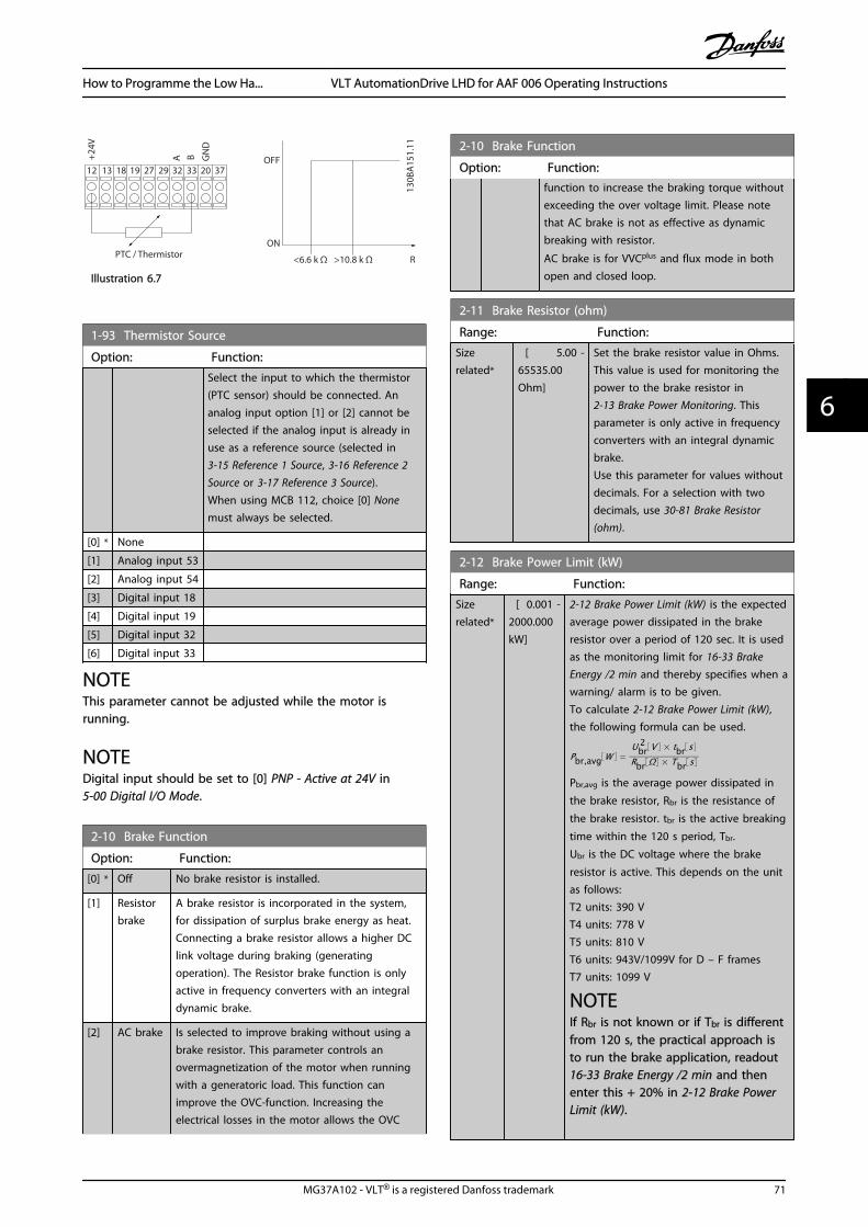
PTC / Thermistor
OFF
ON
+24V
12 13 18 3732A
2719 29 33
B
20
GN
D
R<6.6 k Ω >10.8 k Ω
130B
A15
1.11
Illustration 6.7
1-93 Thermistor Source
Option: Function:
Select the input to which the thermistor(PTC sensor) should be connected. Ananalog input option [1] or [2] cannot beselected if the analog input is already inuse as a reference source (selected in3-15 Reference 1 Source, 3-16 Reference 2Source or 3-17 Reference 3 Source).When using MCB 112, choice [0] Nonemust always be selected.
[0] * None
[1] Analog input 53
[2] Analog input 54
[3] Digital input 18
[4] Digital input 19
[5] Digital input 32
[6] Digital input 33
NOTEThis parameter cannot be adjusted while the motor isrunning.
NOTEDigital input should be set to [0] PNP - Active at 24V in5-00 Digital I/O Mode.
2-10 Brake Function
Option: Function:
[0] * Off No brake resistor is installed.
[1] Resistorbrake
A brake resistor is incorporated in the system,for dissipation of surplus brake energy as heat.Connecting a brake resistor allows a higher DClink voltage during braking (generatingoperation). The Resistor brake function is onlyactive in frequency converters with an integraldynamic brake.
[2] AC brake Is selected to improve braking without using abrake resistor. This parameter controls anovermagnetization of the motor when runningwith a generatoric load. This function canimprove the OVC-function. Increasing theelectrical losses in the motor allows the OVC
2-10 Brake Function
Option: Function:function to increase the braking torque withoutexceeding the over voltage limit. Please notethat AC brake is not as effective as dynamicbreaking with resistor.
AC brake is for VVCplus and flux mode in bothopen and closed loop.
2-11 Brake Resistor (ohm)
Range: Function:
Sizerelated*
[ 5.00 -65535.00Ohm]
Set the brake resistor value in Ohms.This value is used for monitoring thepower to the brake resistor in2-13 Brake Power Monitoring. Thisparameter is only active in frequencyconverters with an integral dynamicbrake.Use this parameter for values withoutdecimals. For a selection with twodecimals, use 30-81 Brake Resistor(ohm).
2-12 Brake Power Limit (kW)
Range: Function:
Sizerelated*
[ 0.001 -2000.000kW]
2-12 Brake Power Limit (kW) is the expectedaverage power dissipated in the brakeresistor over a period of 120 sec. It is usedas the monitoring limit for 16-33 BrakeEnergy /2 min and thereby specifies when awarning/ alarm is to be given.To calculate 2-12 Brake Power Limit (kW),the following formula can be used.
Pbr,avg W =Ubr
2 V × tbr sRbr Ω × Tbr s
Pbr,avg is the average power dissipated in
the brake resistor, Rbr is the resistance of
the brake resistor. tbr is the active breaking
time within the 120 s period, Tbr.
Ubr is the DC voltage where the brake
resistor is active. This depends on the unitas follows:T2 units: 390 VT4 units: 778 VT5 units: 810 VT6 units: 943V/1099V for D – F framesT7 units: 1099 V
NOTEIf Rbr is not known or if Tbr is differentfrom 120 s, the practical approach isto run the brake application, readout16-33 Brake Energy /2 min and thenenter this + 20% in 2-12 Brake PowerLimit (kW).
How to Programme the Low Ha... VLT AutomationDrive LHD for AAF 006 Operating Instructions
MG37A102 - VLT® is a registered Danfoss trademark 71
6 6
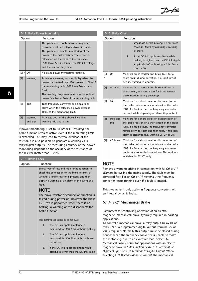
2-13 Brake Power Monitoring
Option: Function:
This parameter is only active in frequencyconverters with an integral dynamic brake.This parameter enables monitoring of thepower to the brake resistor. The power iscalculated on the basis of the resistance(2-11 Brake Resistor (ohm)), the DC link voltage,and the resistor duty time.
[0] * Off No brake power monitoring required.
[1] Warning Activates a warning on the display when thepower transmitted over 120 s exceeds 100% ofthe monitoring limit (2-12 Brake Power Limit(kW) ).The warning disappears when the transmittedpower falls below 80% of the monitoring limit.
[2] Trip Trips frequency converter and displays analarm when the calculated power exceeds100% of the monitoring limit.
[3] Warningand trip
Activates both of the above, includingwarning, trip and alarm.
If power monitoring is set to [0] Off or [1] Warning, thebrake function remains active, even if the monitoring limitis exceeded. This may lead to thermal overload of theresistor. It is also possible to generate a warning via arelay/digital outputs. The measuring accuracy of the powermonitoring depends on the accuracy of the resistance ofthe resistor (better than ± 20%).
2-15 Brake Check
Option: Function:
Select type of test and monitoring function tocheck the connection to the brake resistor, orwhether a brake resistor is present, and thendisplay a warning or an alarm in the event of afault.
NOTEThe brake resistor disconnection function istested during power-up. However the brakeIGBT test is performed when there is nobraking. A warning or trip disconnects thebrake function.
The testing sequence is as follows:
1. The DC link ripple amplitude ismeasured for 300 Æms without braking.
2. The DC link ripple amplitude ismeasured for 300 Æms with the braketurned on.
3. If the DC link ripple amplitude whilebraking is lower than the DC link ripple
2-15 Brake Check
Option: Function:amplitude before braking + 1 %: Brakecheck has failed by returning a warningor alarm.
4. If the DC link ripple amplitude whilebraking is higher than the DC link rippleamplitude before braking + 1 %: Brakecheck is OK.
[0]*
Off Monitors brake resistor and brake IGBT for ashort-circuit during operation. If a short-circuitoccurs, warning 25 appears.
[1] Warning Monitors brake resistor and brake IGBT for ashort-circuit, and runs a test for brake resistordisconnection during power-up.
[2] Trip Monitors for a short-circuit or disconnection ofthe brake resistor, or a short-circuit of the brakeIGBT. If a fault occurs, the frequency convertercuts out while displaying an alarm (trip locked).
[3] Stop andtrip
Monitors for a short-circuit or disconnection ofthe brake resistor, or a short-circuit of the brakeIGBT. If a fault occurs, the frequency converterramps down to coast and then trips. A trip lockalarm is displayed (e.g. warning 25, 27 or 28).
[4] AC brake Monitors for a short-circuit or disconnection ofthe brake resistor, or a short-circuit of the brakeIGBT. If a fault occurs, the frequency converterperforms a controlled ramp-down. This option isavailable for FC 302 only.
NOTERemove a warning arising in connection with [0] Off or [1]Warning by cycling the mains supply. The fault must becorrected first. For [0] Off or [1] Warning , the frequencyconverter keeps running even if a fault is located.
This parameter is only active in frequency converters withan integral dynamic brake.
6.1.4 2-2* Mechanical Brake
Parameters for controlling operation of an electro-magnetic (mechanical) brake, typically required in hoistingapplications.To control a mechanical brake, a relay output (relay 01 orrelay 02) or a programmed digital output (terminal 27 or29) is required. Normally this output must be closed duringperiods when the frequency converter is unable to ‘hold’the motor, e.g. due to an excessive load. Select [32]Mechanical Brake Control for applications with an electro-magnetic brake in 5-40 Function Relay, 5-30 Terminal 27Digital Output, or 5-31 Terminal 29 Digital Output. Whenselecting [32] Mechanical brake control, the mechanical
How to Programme the Low Ha... VLT AutomationDrive LHD for AAF 006 Operating Instructions
72 MG37A102 - VLT® is a registered Danfoss trademark
66

brake is closed from start up until the output current isabove the level selected in 2-20 Release Brake Current.During stop, the mechanical brake activates when thespeed falls below the level specified in 2-21 Activate BrakeSpeed [RPM]. If the frequency converter enters an alarmcondition or an over-current or over-voltage situation, themechanical brake immediately cuts in. This is also the caseduring safe stop.
NOTEProtection mode and trip delay features (14-25 Trip Delayat Torque Limit and 14-26 Trip Delay at Inverter Fault) maydelay the activation of the mechanical brake in an alarmcondition. These features must be disabled in hoistingapplications.
Startterm.18
1=on
0=o
Shaft speed
Start delay time
on
o
Brake delay time
Time
Output current
Relay 01
Pre-magnetizingcurrent orDC hold current
Reaction time EMK brake
Par 2-20Release brake currentPar 1-76 Start current/
Par 2-00 DC hold current
Par 1-74Start speed
Par 2-21Activate brake speed
Mechanical brakelocked
Mechanical brakefree
Par 1-71
Par 2-23
130B
A07
4.12
Illustration 6.8
2-20 Release Brake Current
Range: Function:
par. 16-37 A* [0.00 - par. 16-37 A]
2-21 Activate Brake Speed [RPM]
Range: Function:
0 RPM* [0 - 30000RPM]
Set the motor speed for activation ofthe mechanical brake, when a stopcondition is present. The upper speedlimit is specified in 4-53 Warning SpeedHigh.
2-22 Activate Brake Speed [Hz]
Range: Function:
0 Hz* [0.0 - 5000.0 Hz]
2-23 Activate Brake Delay
Range: Function:
0.0 s* [0.0 -5.0 s]
Enter the brake delay time of the coast afterramp-down time. The shaft is held at zerospeed with full holding torque. Ensure that the
2-23 Activate Brake Delay
Range: Function:mechanical brake has locked the load beforethe motor enters coast mode. See MechanicalBrake Control in the FC 300 Design Guide,MG33BXYY.
2-24 Stop Delay
Range: Function:
0.0 s* [0.0 - 5.0 s] Set the time interval from the momentwhen the motor is stopped until the brakecloses. This parameter is a part of thestopping function.
2-25 Brake Release Time
Range: Function:
0.20 s* [0.00 - 5.00s]
This value defines the time it takes forthe mechanical brake to open. Thisparameter must act as a time-out whenbrake feedback is activated.
How to Programme the Low Ha... VLT AutomationDrive LHD for AAF 006 Operating Instructions
MG37A102 - VLT® is a registered Danfoss trademark 73
6 6

2-26 Torque Ref
Range: Function:
0.00 %* [0 - 0 %] The value defines the torque applied againstthe closed mechanical brake, before release
2-27 Torque Ramp Time
Range: Function:
0.2 s* [0.0 - 5.0 s] The value defines the duration of the torqueramp in clockwise direction.
2-28 Gain Boost Factor
Range: Function:
1.00 N/A* [1.00 - 4.00N/A]
Only active in flux closed loop. Thefunction ensures a smooth transitionfrom torque control mode to speedcontrol mode when the motor takesover the load from the brake.
Mech.Brake
GainBoost
Relay
Torqueref.
MotorSpeed Premag Torque Ramp
Timep. 2-27
Torque Ref. 2-26
Gain Boost Factorp. 2-28
BrakeReleaseTimep. 2-25
Ramp 1 upp. 3-41
Ramp 1 downp. 3-42
StopDelayp. 2-24
ActivateBrakeDelayp. 2-23
1 2 3
130B
A64
2.12
II
I
Illustration 6.9 Brake release sequence for hoist mechanical brake controlI) Activate brake delay: The frequency converter starts again from the mechanical brake engaged position.II) Stop delay: When the time between successive starts is shorter than the setting in 2-24 Stop Delay, the frequency converter startswithout applying the mechanical brake (e.g. reversing).
3-10 Preset Reference
Array [8]Range: 0-7
Range: Function:
0.00%*
[-100.00 -100.00 %]
Enter up to eight different preset references(0-7) in this parameter, using arrayprogramming. The preset reference is statedas a percentage of the value RefMAX
(3-03 Maximum Reference) If a RefMIN
different from 0 (3-02 Minimum Reference) isprogrammed, the preset reference iscalculated as a percentage of the fullreference range, i.e. on the basis of thedifference between RefMAX and RefMIN.
Afterwards, the value is added to RefMIN.
When using preset references, select Presetref. bit 0/1/2 [16], [17] or [18] for the
3-10 Preset Reference
Array [8]Range: 0-7
Range: Function:corresponding digital inputs in parametergroup 5-1*.
How to Programme the Low Ha... VLT AutomationDrive LHD for AAF 006 Operating Instructions
74 MG37A102 - VLT® is a registered Danfoss trademark
66

[P 5-13=Preset ref. bit 0]
Preset
[P 5-14=Preset ref. bit 1]
[P 5-15=Preset ref. bit 2]
10101010
76543210
29
12 (+24V)
11001100 32
11110000 33
130B
A14
9.10
Illustration 6.10
Preset ref. bit 2 1 0
Preset ref. 0 0 0 0
Preset ref. 1 0 0 1
Preset ref. 2 0 1 0
Preset ref. 3 0 1 1
Preset ref. 4 1 0 0
Preset ref. 5 1 0 1
Preset ref. 6 1 1 0
Preset ref. 7 1 1 1
Table 6.4
3-11 Jog Speed [Hz]
Range: Function:
0 Hz* [0.0 - par. 4-14 Hz]
3-15 Reference Resource 1
Option: Function:
Select the reference input to be usedfor the first reference signal. 3-15 Reference Resource 1, 3-16 Reference Resource 2 and 3-17 Reference Resource 3 define up tothree different reference signals. Thesum of these reference signalsdefines the actual reference.
[0] * No function
[1] * Analog input 53
[2] Analog input 54
[7] Frequency input 29
[8] Frequency input 33
[11] Local bus reference
[20] Digital pot.meter
[21] Analog input X30-11 (General Purpose I/O Option Module)
[22] Analog input X30-12 (General Purpose I/O Option Module)
3-16 Reference Resource 2
Option: Function:
Select the reference input to beused for the second referencesignal. 3-15 Reference Resource 1,
3-16 Reference Resource 2
Option: Function:3-16 Reference Resource 2 and 3-17 Reference Resource 3 define upto three different reference signals.The sum of these reference signalsdefines the actual reference.
[0] * No function
[1] Analog input 53
[2] Analog input 54
[7] Frequency input 29
[8] Frequency input 33
[11] Local bus reference
[20] * Digital pot.meter
[21] Analog input X30-11
[22] Analog input X30-12
3-17 Reference Resource 3
Option: Function:
Select the reference input to beused for the third reference signal. 3-15 Reference Resource 1, 3-16 Reference Resource 2 and 3-17 Reference Resource 3 define upto three different reference signals.The sum of these reference signalsdefines the actual reference.
[0] No function
[1] Analog input 53
[2] Analog input 54
[7] Frequency input 29
[8] Frequency input 33
[11] * Local bus reference
[20] Digital pot.meter
[21] Analog input X30-11
[22] Analog input X30-12
5-00 Digital I/O Mode
Option: Function:
Digital inputs and programmed digital outputs arepre-programmable for operation either in PNP or NPNsystems.
[0] * PNP Action on positive directional pulses (). PNP systemsare pulled down to GND.
[1] NPN Action on negative directional pulses (). NPNsystems are pulled up to +24 V, internally in thefrequency converter.
NOTEOnce this parameter has been changed, it must beactivated by performing a power cycle.
How to Programme the Low Ha... VLT AutomationDrive LHD for AAF 006 Operating Instructions
MG37A102 - VLT® is a registered Danfoss trademark 75
6 6

5-01 Terminal 27 Mode
Option: Function:
[0] * Input Defines terminal 27 as a digital input.
[1] Output Defines terminal 27 as a digital output.
NOTEThis parameter cannot be changed while the motor isrunning.
5-02 Terminal 29 Mode
Option: Function:
[0] * Input Defines terminal 29 as a digital input.
[1] Output Defines terminal 29 as a digital output.
This parameter is available for FC 302 only.
6.1.5 Digital Inputs
The digital inputs are used for selecting various functionsin the frequency converter. All digital inputs can be set tothe following functions:
Digital input function Select TerminalNo operation [0] All *term 32, 33
Reset [1] All
Coast inverse [2] All *term 27
Coast and reset inverse [3] All
Quick stop inverse [4] All
DC-brake inverse [5] All
Stop inverse [6] All
Start [8] All *term 18
Latched start [9] All
Reversing [10] All *term 19
Start reversing [11] All
Enable start forward [12] All
Enable start reverse [13] All
Jog [14] All *term 29
Preset reference on [15] All
Preset ref bit 0 [16] All
Preset ref bit 1 [17] All
Preset ref bit 2 [18] All
Freeze reference [19] All
Freeze output [20] All
Speed up [21] All
Speed down [22] All
Set-up select bit 0 [23] All
Set-up select bit 1 [24] All
Precise stop inverse [26] 18, 19
Precises start, stop [27] 18, 19
Catch up [28] All
Slow down [29] All
Counter input [30] 29, 33
Pulse input Edge Trigged [31] 29, 33
Digital input function Select TerminalPulse input Time Based [32] 29, 33
Ramp bit 0 [34] All
Ramp bit 1 [35] All
Latched precise start [40] 18, 19
Latched precise stopinverse
[41] 18, 19
External interlock [51]
DigiPot Increase [55] All
DigiPot Decrease [56] All
DigiPot Clear [57] All
Digipot Hoist [58] All
Counter A (up) [60] 29, 33
Counter A (down) [61] 29, 33
Reset Counter A [62] All
Counter B (up) [63] 29, 33
Counter B (down) [64] 29, 33
Reset Counter B [65] All
Mech. Brake Feedb. [70] All
Mech. Brake Feedb. Inv. [71] All
PID Error Inv. [72] All
PID Reset I-part [73] All
PID enable [74] All
PTC Card 1 [80] All
Profidrive OFF2 [91]
Profidrive OFF3 [92]
Start edge triggered [98]
Safe Option Reset [100]
Table 6.5
FC 300 standard terminals are 18, 19, 27, 29, 32 and 33.MCB 101 terminals are X30/2, X30/3 and X30/4.Terminal 29 functions as an output only in FC 302.
Functions dedicated to only one digital input are stated inthe associated parameter.
All digital inputs can be programmed to these functions:
[0] Nooperation
No reaction to signals transmitted to theterminal.
[1] Reset Resets frequency converter after a TRIP/ALARM. Not all alarms can be reset.
[2] Coastinverse
(Default Digital input 27): Coasting stop,inverted input (NC). The frequency converterleaves the motor in free mode. Logic ‘0’ =>coasting stop.
[3] Coast andreset inverse
Reset and coasting stop Inverted input (NC).Leaves motor in free mode and resetsfrequency converter. Logic ‘0’ => coastingstop and reset.
[4] Quick stopinverse
Inverted input (NC). Generates a stop inaccordance with quick-stop ramp time set in3-81 Quick Stop Ramp Time. When motor
How to Programme the Low Ha... VLT AutomationDrive LHD for AAF 006 Operating Instructions
76 MG37A102 - VLT® is a registered Danfoss trademark
66
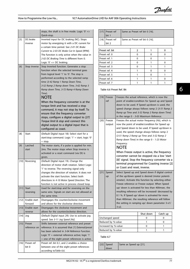
stops, the shaft is in free mode. Logic ‘0’ =>Quick-stop.
[5] DC-brakeinverse
Inverted input for DC braking (NC). Stopsmotor by energizing it with a DC current fora certain time period. See 2-01 DC BrakeCurrent to 2-03 DC Brake Cut In Speed [RPM].The function is only active when the value in2-02 DC Braking Time is different from 0.Logic ’0’ => DC braking.
[6] Stop inverse Stop Inverted function. Generates a stopfunction when the selected terminal goesfrom logical level ‘1’ to ‘0’. The stop isperformed according to the selected ramptime (3-42 Ramp 1 Ramp Down Time,3-52 Ramp 2 Ramp down Time, 3-62 Ramp 3Ramp down Time, 3-72 Ramp 4 Ramp DownTime).
NOTEWhen the frequency converter is at thetorque limit and has received a stopcommand, it may not stop by itself. Toensure that the frequency converterstops, configure a digital output to [27]Torque limit & stop and connect thisdigital output to a digital input that isconfigured as coast.
[8] Start (Default Digital input 18): Select start for astart/stop command. Logic ‘1’ = start, logic ‘0’= stop.
[9] Latchedstart
The motor starts, if a pulse is applied for min.2ms. The motor stops when Stop inverse isactivated or a reset command (via DI) isgiven.
[10] Reversing (Default Digital input 19). Change thedirection of motor shaft rotation. Select Logic‘1’ to reverse. The reversing signal onlychanges the direction of rotation. It does notactivate the start function. Select bothdirections in 4-10 Motor Speed Direction. Thefunction is not active in process closed loop.
[11] Startreversing
Used for start/stop and for reversing on thesame wire. Signals on start are not allowed atthe same time.
[12] Enable startforward
Disengages the counterclockwise movementand allows for the clockwise direction.
[13] Enable startreverse
Disengages the clockwise movement andallows for the counterclockwise direction.
[14] Jog (Default Digital input 29): Use to activate jogspeed. See 3-11 Jog Speed [Hz].
[15] Presetreference on
Shifts between external reference and presetreference. It is assumed that [1] External/presethas been selected in 3-04 Reference Function.Logic '0' = external reference active; logic '1'= one of the eight preset references is active.
[16] Preset refbit 0
Preset ref. bit 0,1, and 2 enables a choicebetween one of the eight preset referencesaccording toTable 6.6.
[17] Preset refbit 1
Same as Preset ref bit 0 [16].
[18] Preset refbit 2
Same as Preset ref bit 0 [16].
Preset ref. bit 2 1 0
Preset ref. 0 0 0 0
Preset ref. 1 0 0 1
Preset ref. 2 0 1 0
Preset ref. 3 0 1 1
Preset ref. 4 1 0 0
Preset ref. 5 1 0 1
Preset ref. 6 1 1 0
Preset ref. 7 1 1 1
Table 6.6 Preset Ref. Bit
[19] Freezeref
Freezes the actual reference, which is now thepoint of enable/condition for Speed up and Speeddown to be used. If Speed up/down is used, thespeed change always follows ramp 2 (3-51 Ramp 2Ramp up Time and 3-52 Ramp 2 Ramp down Time)in the range 0 - 3-03 Maximum Reference.
[20] Freezeoutput
Freezes the actual motor frequency (Hz), which isnow the point of enable/condition for Speed upand Speed down to be used. If Speed up/down isused, the speed change always follows ramp 2(3-51 Ramp 2 Ramp up Time and 3-52 Ramp 2Ramp down Time) in the range 0 - 1-23 MotorFrequency.
NOTEWhen Freeze output is active, the frequencyconverter cannot be stopped via a low ‘start[8]’ signal. Stop the frequency converter via aterminal programmed for Coasting inverse [2]or Coast and reset, inverse.
[21] Speedup
Select Speed up and Speed down if digital controlof the up/down speed is desired (motor potenti-ometer). Activate this function by selecting eitherFreeze reference or Freeze output. When Speedup/ down is activated for less than 400msec. theresulting reference will be increased/ decreased by0.1 %. If Speed up/ down is activated for morethan 400msec. the resulting reference will followthe setting in ramping up/ down parameter 3-x1/3-x2.
Shut down Catch up
Unchanged speed 0 0
Reduced by %-value 1 0
Increased by %-value 0 1
Reduced by %-value 1 1
Table 6.7
[22] Speeddown
Same as Speed up [21].
How to Programme the Low Ha... VLT AutomationDrive LHD for AAF 006 Operating Instructions
MG37A102 - VLT® is a registered Danfoss trademark 77
6 6

[23] Set-upselect bit0
Select Set-up select bit 0 or Select Set-up selectbit 1 to select one of the four set-ups. Set0-10 Active Set-up to Multi Set-up.
[24] Set-upselect bit1
(Default Digital input 32): Same as Set-up selectbit 0 [23].
[26] Precisestop inv.
Sends an inverted stop signal when the precisestop function is activated in 1-83 Precise StopFunction.Precise stop inverse function is available forterminals 18 or 19.
[27] Precisestart, stop
Use when Precise ramp stop [0] is selected in1-83 Precise Stop Function.Precise start, stop is available for terminals 18and 19.Precise start makes sure that the angle that therotor turns from standing still to reference is thesame for each start (for same ramp time, sameset-point). This is the equivalent to the precisestop where the angle that the rotor turns fromreference to standing still is the same for eachstop.When using for 1-83 Precise Stop Function [1] or[2]:The frequency converter needs a Precise Stopsignal before the value of 1-84 Precise StopCounter Value is reached. If this is not supplied,the frequency converter will not stop when thevalue in 1-84 Precise Stop Counter Value isreached.Precise start, stop must be triggered by a DigitalInput and is available for terminals 18 and 19.
[28] Catch up Increases reference value by percentage(relative) set in 3-12 Catch up/slow Down Value.
[29] Slowdown
Reduces reference value by percentage (relative)set in 3-12 Catch up/slow Down Value.
[30] Counterinput
Precise stop function in 1-83 Precise StopFunction acts as Counter stop or speedcompensated counter stop with or withoutreset. The counter value must be set in1-84 Precise Stop Counter Value.
[31] Pulseedgetriggered
Edge triggered pulse input counts number ofpulse flanks per sample time. This gives a higherresolution at high frequencies, but is not asprecise at lower frequencies. Use this pulseprinciple for encoders with very low resolution(e.g. 30 ppr).
Pulse
Sample time
130B
B463
.10
Illustration 6.11
[32] Pulse timebased
Time based pulse input measures the durationbetween flanks. This gives a higher resolution atlower frequencies, but is not as precise athigher frequencies. This principle has a cut-off
frequency which makes it unsuited for encoderswith very low resolutions (e.g. 30 ppr) at lowspeeds.
Speed [rpm] Speed [rpm]
Time[sec] Time[sec]a b 130B
B462
.10
a: very low encoderresolution
b: standard encoderresolution
Table 6.8
Read Timer:20 timer tides
Read Timer:20 timer tides
Time StartTime counterSample timeTimerPulse
130B
B464
.10
Illustration 6.12
[34] Ramp bit0
Enables a choice between one of the 4 rampsavailable, according to the table below.
[35] Ramp bit1
Same as Ramp bit 0.
Preset ramp bit 1 0
Ramp 1 0 0
Ramp 2 0 1
Ramp 3 1 0
Ramp 4 1 1
Table 6.9
[40] LatchedPrecise Start
A latched Precise Start only requires a pulseof 3ms on T18 or T19.When using for 1-83 [1] or [2]:When the reference is reached, thefrequency converter will internally enablethe Precise Stop signal. This means that thefrequency converter will do the PreciseStop when the counter value of 1-84 PreciseStop Counter Value is reached.
[41] LatchedPrecise Stopinverse
Sends a latched stop signal when theprecise stop function is activated in1-83 Precise Stop Function. The LatchedPrecise stop inverse function is available forterminals 18 or 19.
[51] Externalinterlock
This function makes it possible to give anexternal fault to the drive. This fault istreated in the same way as an internallygenerated alarm.
[55] DigiPotIncrease
INCREASE signal to the Digital Potenti-ometer function described in parametergroup 3-9*
How to Programme the Low Ha... VLT AutomationDrive LHD for AAF 006 Operating Instructions
78 MG37A102 - VLT® is a registered Danfoss trademark
66
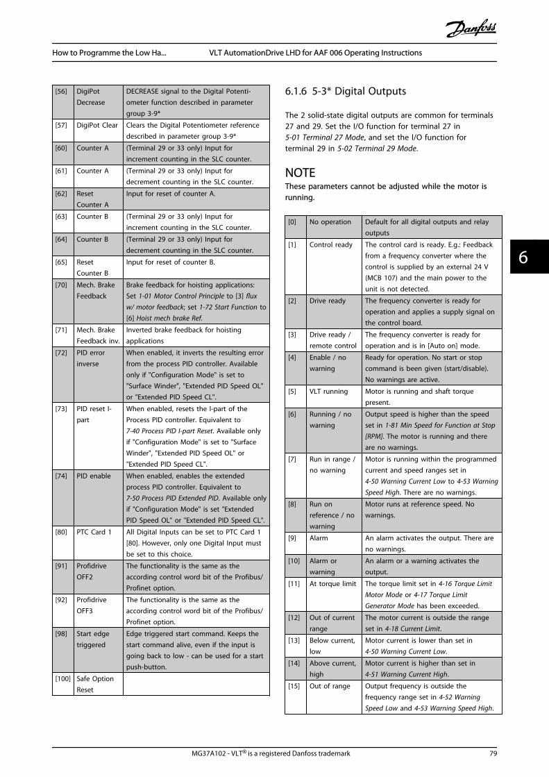
[56] DigiPotDecrease
DECREASE signal to the Digital Potenti-ometer function described in parametergroup 3-9*
[57] DigiPot Clear Clears the Digital Potentiometer referencedescribed in parameter group 3-9*
[60] Counter A (Terminal 29 or 33 only) Input forincrement counting in the SLC counter.
[61] Counter A (Terminal 29 or 33 only) Input fordecrement counting in the SLC counter.
[62] ResetCounter A
Input for reset of counter A.
[63] Counter B (Terminal 29 or 33 only) Input forincrement counting in the SLC counter.
[64] Counter B (Terminal 29 or 33 only) Input fordecrement counting in the SLC counter.
[65] ResetCounter B
Input for reset of counter B.
[70] Mech. BrakeFeedback
Brake feedback for hoisting applications:Set 1-01 Motor Control Principle to [3] fluxw/ motor feedback; set 1-72 Start Function to[6] Hoist mech brake Ref.
[71] Mech. BrakeFeedback inv.
Inverted brake feedback for hoistingapplications
[72] PID errorinverse
When enabled, it inverts the resulting errorfrom the process PID controller. Availableonly if "Configuration Mode" is set to"Surface Winder", "Extended PID Speed OL"or "Extended PID Speed CL".
[73] PID reset I-part
When enabled, resets the I-part of theProcess PID controller. Equivalent to7-40 Process PID I-part Reset. Available onlyif "Configuration Mode" is set to "SurfaceWinder", "Extended PID Speed OL" or"Extended PID Speed CL".
[74] PID enable When enabled, enables the extendedprocess PID controller. Equivalent to7-50 Process PID Extended PID. Available onlyif "Configuration Mode" is set "ExtendedPID Speed OL" or "Extended PID Speed CL".
[80] PTC Card 1 All Digital Inputs can be set to PTC Card 1[80]. However, only one Digital Input mustbe set to this choice.
[91] ProfidriveOFF2
The functionality is the same as theaccording control word bit of the Profibus/Profinet option.
[92] ProfidriveOFF3
The functionality is the same as theaccording control word bit of the Profibus/Profinet option.
[98] Start edgetriggered
Edge triggered start command. Keeps thestart command alive, even if the input isgoing back to low - can be used for a startpush-button.
[100] Safe OptionReset
6.1.6 5-3* Digital Outputs
The 2 solid-state digital outputs are common for terminals27 and 29. Set the I/O function for terminal 27 in 5-01 Terminal 27 Mode, and set the I/O function forterminal 29 in 5-02 Terminal 29 Mode.
NOTEThese parameters cannot be adjusted while the motor isrunning.
[0] No operation Default for all digital outputs and relayoutputs
[1] Control ready The control card is ready. E.g.: Feedbackfrom a frequency converter where thecontrol is supplied by an external 24 V(MCB 107) and the main power to theunit is not detected.
[2] Drive ready The frequency converter is ready foroperation and applies a supply signal onthe control board.
[3] Drive ready /remote control
The frequency converter is ready foroperation and is in [Auto on] mode.
[4] Enable / nowarning
Ready for operation. No start or stopcommand is been given (start/disable).No warnings are active.
[5] VLT running Motor is running and shaft torquepresent.
[6] Running / nowarning
Output speed is higher than the speedset in 1-81 Min Speed for Function at Stop[RPM]. The motor is running and thereare no warnings.
[7] Run in range /no warning
Motor is running within the programmedcurrent and speed ranges set in4-50 Warning Current Low to 4-53 WarningSpeed High. There are no warnings.
[8] Run onreference / nowarning
Motor runs at reference speed. Nowarnings.
[9] Alarm An alarm activates the output. There areno warnings.
[10] Alarm orwarning
An alarm or a warning activates theoutput.
[11] At torque limit The torque limit set in 4-16 Torque LimitMotor Mode or 4-17 Torque LimitGenerator Mode has been exceeded.
[12] Out of currentrange
The motor current is outside the rangeset in 4-18 Current Limit.
[13] Below current,low
Motor current is lower than set in4-50 Warning Current Low.
[14] Above current,high
Motor current is higher than set in4-51 Warning Current High.
[15] Out of range Output frequency is outside thefrequency range set in 4-52 WarningSpeed Low and 4-53 Warning Speed High.
How to Programme the Low Ha... VLT AutomationDrive LHD for AAF 006 Operating Instructions
MG37A102 - VLT® is a registered Danfoss trademark 79
6 6
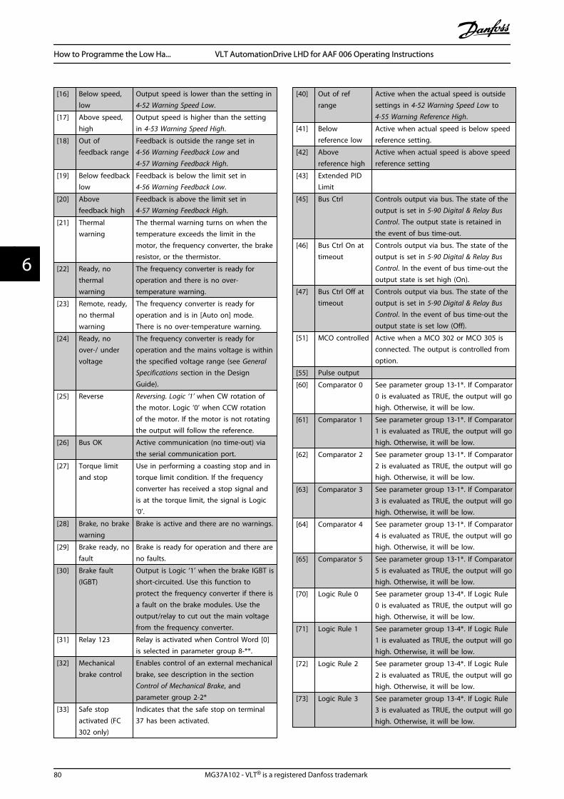
[16] Below speed,low
Output speed is lower than the setting in4-52 Warning Speed Low.
[17] Above speed,high
Output speed is higher than the settingin 4-53 Warning Speed High.
[18] Out offeedback range
Feedback is outside the range set in4-56 Warning Feedback Low and4-57 Warning Feedback High.
[19] Below feedbacklow
Feedback is below the limit set in4-56 Warning Feedback Low.
[20] Abovefeedback high
Feedback is above the limit set in4-57 Warning Feedback High.
[21] Thermalwarning
The thermal warning turns on when thetemperature exceeds the limit in themotor, the frequency converter, the brakeresistor, or the thermistor.
[22] Ready, nothermalwarning
The frequency converter is ready foroperation and there is no over-temperature warning.
[23] Remote, ready,no thermalwarning
The frequency converter is ready foroperation and is in [Auto on] mode.There is no over-temperature warning.
[24] Ready, noover-/ undervoltage
The frequency converter is ready foroperation and the mains voltage is withinthe specified voltage range (see GeneralSpecifications section in the DesignGuide).
[25] Reverse Reversing. Logic ‘1’ when CW rotation ofthe motor. Logic ‘0’ when CCW rotationof the motor. If the motor is not rotatingthe output will follow the reference.
[26] Bus OK Active communication (no time-out) viathe serial communication port.
[27] Torque limitand stop
Use in performing a coasting stop and intorque limit condition. If the frequencyconverter has received a stop signal andis at the torque limit, the signal is Logic‘0’.
[28] Brake, no brakewarning
Brake is active and there are no warnings.
[29] Brake ready, nofault
Brake is ready for operation and there areno faults.
[30] Brake fault(IGBT)
Output is Logic ‘1’ when the brake IGBT isshort-circuited. Use this function toprotect the frequency converter if there isa fault on the brake modules. Use theoutput/relay to cut out the main voltagefrom the frequency converter.
[31] Relay 123 Relay is activated when Control Word [0]is selected in parameter group 8-**.
[32] Mechanicalbrake control
Enables control of an external mechanicalbrake, see description in the sectionControl of Mechanical Brake, andparameter group 2-2*
[33] Safe stopactivated (FC302 only)
Indicates that the safe stop on terminal37 has been activated.
[40] Out of refrange
Active when the actual speed is outsidesettings in 4-52 Warning Speed Low to4-55 Warning Reference High.
[41] Belowreference low
Active when actual speed is below speedreference setting.
[42] Abovereference high
Active when actual speed is above speedreference setting
[43] Extended PIDLimit
[45] Bus Ctrl Controls output via bus. The state of theoutput is set in 5-90 Digital & Relay BusControl. The output state is retained inthe event of bus time-out.
[46] Bus Ctrl On attimeout
Controls output via bus. The state of theoutput is set in 5-90 Digital & Relay BusControl. In the event of bus time-out theoutput state is set high (On).
[47] Bus Ctrl Off attimeout
Controls output via bus. The state of theoutput is set in 5-90 Digital & Relay BusControl. In the event of bus time-out theoutput state is set low (Off).
[51] MCO controlled Active when a MCO 302 or MCO 305 isconnected. The output is controlled fromoption.
[55] Pulse output
[60] Comparator 0 See parameter group 13-1*. If Comparator0 is evaluated as TRUE, the output will gohigh. Otherwise, it will be low.
[61] Comparator 1 See parameter group 13-1*. If Comparator1 is evaluated as TRUE, the output will gohigh. Otherwise, it will be low.
[62] Comparator 2 See parameter group 13-1*. If Comparator2 is evaluated as TRUE, the output will gohigh. Otherwise, it will be low.
[63] Comparator 3 See parameter group 13-1*. If Comparator3 is evaluated as TRUE, the output will gohigh. Otherwise, it will be low.
[64] Comparator 4 See parameter group 13-1*. If Comparator4 is evaluated as TRUE, the output will gohigh. Otherwise, it will be low.
[65] Comparator 5 See parameter group 13-1*. If Comparator5 is evaluated as TRUE, the output will gohigh. Otherwise, it will be low.
[70] Logic Rule 0 See parameter group 13-4*. If Logic Rule0 is evaluated as TRUE, the output will gohigh. Otherwise, it will be low.
[71] Logic Rule 1 See parameter group 13-4*. If Logic Rule1 is evaluated as TRUE, the output will gohigh. Otherwise, it will be low.
[72] Logic Rule 2 See parameter group 13-4*. If Logic Rule2 is evaluated as TRUE, the output will gohigh. Otherwise, it will be low.
[73] Logic Rule 3 See parameter group 13-4*. If Logic Rule3 is evaluated as TRUE, the output will gohigh. Otherwise, it will be low.
How to Programme the Low Ha... VLT AutomationDrive LHD for AAF 006 Operating Instructions
80 MG37A102 - VLT® is a registered Danfoss trademark
66
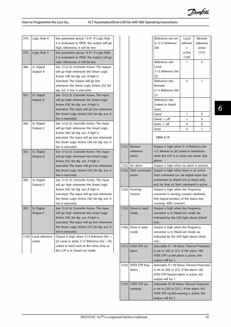
[74] Logic Rule 4 See parameter group 13-4*. If Logic Rule4 is evaluated as TRUE, the output will gohigh. Otherwise, it will be low.
[75] Logic Rule 5 See parameter group 13-4*. If Logic Rule5 is evaluated as TRUE, the output will gohigh. Otherwise, it will be low.
[80] SL DigitalOutput A
See 13-52 SL Controller Action. The outputwill go high whenever the Smart LogicAction [38] Set dig. out. A high isexecuted. The output will go lowwhenever the Smart Logic Action [32] Setdig. out. A low is executed.
[81] SL DigitalOutput B
See 13-52 SL Controller Action. The inputwill go high whenever the Smart LogicAction [39] Set dig. out. A high isexecuted. The input will go low wheneverthe Smart Logic Action [33] Set dig. out. Alow is executed.
[82] SL DigitalOutput C
See 13-52 SL Controller Action. The inputwill go high whenever the Smart LogicAction [40] Set dig. out. A high isexecuted. The input will go low wheneverthe Smart Logic Action [34] Set dig. out. Alow is executed.
[83] SL DigitalOutput D
See 13-52 SL Controller Action. The inputwill go high whenever the Smart LogicAction [41] Set dig. out. A high isexecuted. The input will go low wheneverthe Smart Logic Action [35] Set dig. out. Alow is executed.
[84] SL DigitalOutput E
See 13-52 SL Controller Action. The inputwill go high whenever the Smart LogicAction [42] Set dig. out. A high isexecuted. The input will go low wheneverthe Smart Logic Action [36] Set dig. out. Alow is executed.
[85] SL DigitalOutput F
See 13-52 SL Controller Action. The inputwill go high whenever the Smart LogicAction [43] Set dig. out. A high isexecuted. The input will go low wheneverthe Smart Logic Action [37] Set dig. out. Alow is executed.
[120] Local referenceactive
Output is high when 3-13 Reference Site =[2] Local or when 3-13 Reference Site = [0]Linked to hand auto at the same time asthe LCP is in [Hand on] mode.
Reference site setin 3-13 ReferenceSite
Localreferenc
eactive[120]
Remotereference
active[121]
Reference site:Local3-13 Reference Site[2]
1 0
Reference site:Remote3-13 Reference Site[1]
0 1
Reference site:Linked to Hand/Auto
Hand 1 0
Hand -> off 1 0
Auto -> off 0 0
Auto 0 1
Table 6.10
[121] Remotereferenceactive
Output is high when 3-13 Reference Site=[1] Remote or [0] Linked to hand/autowhile the LCP is in [Auto on] mode. Seeabove.
[122] No alarm Output is high when no alarm is present.
[123] Start commandactive
Output is high when there is an activeStart command (i.e. via digital input busconnection or [Hand on] or [Auto on]),and no Stop or Start command is active.
[124] Runningreverse
Output is high when the frequencyconverter is running counter clockwise(the logical product of the status bits‘running’ AND ‘reverse’).
[125] Drive in handmode
Output is high when the frequencyconverter is in [Hand on] mode (asindicated by the LED light above [Handon]).
[126] Drive in automode
Output is high when the frequencyconverter is in [Hand on] mode (asindicated by the LED light above [Autoon]).
[151] ATEX ETR cur.alarm
Selectable if 1-90 Motor Thermal Protectionis set to [20] or [21]. If the alarm 164ATEX ETR cur.lim.alarm is active, theoutput will be 1.
[152] ATEX ETR freq.alarm
Selectable if 1-90 Motor Thermal Protectionis set to [20] or [21]. If the alarm 166ATEX ETR freq.lim.alarm is active, theoutput will be 1.
[153] ATEX ETR cur.warning
Selectable if1-90 Motor Thermal Protectionis set to [20] or [21] ]. If the alarm 163ATEX ETR cur.lim.warning is active, theoutput will be 1.
How to Programme the Low Ha... VLT AutomationDrive LHD for AAF 006 Operating Instructions
MG37A102 - VLT® is a registered Danfoss trademark 81
6 6

[154] ATEX ETR freq.warning
Selectable if 1-90 Motor Thermal Protectionis set to [20] or [21]. If the warning 165ATEX ETR freq.lim.warning is active, theoutput will be 1.
[188] AHF CapacitorConnect
The capacitors will be turned on at 20%(hysteresis of 50% gives an interval of10% - 30%). The capacitors will be discon-nected below 10%. The off delay is 10sand will restart if the nominal power goesabove 10% during the delay. 5-80 AHFCap Reconnect Delay is used to guaranteea minimum off-time for the capacitors.
[189] External fancontrol
The internal logics for the internal fancontrol is transferred to this output tomake it possible to control an externalfan (relevant for HP duct cooling).
5-40 Function Relay
Array [9](Relay 1 [0], Relay 2 [1], Relay 3 [2] (MCB 113), Relay 4 [3] (MCB113), Relay 5 [4] (MCB 113), Relay 6 [5] (MCB 113), Relay 7 [6](MCB 105), Relay 8 [7] (MCB 105), Relay 9 [8] (MCB 105))
Option: Function:
[0] * No operation All digital and relay outputs are defaultset to “No Operation”.
[1] Control ready The control card is ready. E.g.: Feedbackfrom a drive where the control issupplied by an external 24 V (MCB 107)and the main power to drive is notdetected.
[2] Unit ready Drive is ready to operate. Mains andcontrol supplies are OK.
[4] Enable / nowarning
Ready for operation. No start or stopcommands have been applied (start/disable). No warnings are active.
[5] Running Motor is running, and shaft torquepresent.
[9] Alarm An alarm activates the output. Nowarnings
[10] Alarm or warning An alarm or a warning activates theoutput.
[12] Current limit The motor current is outside the rangeset in 4-18 Current Limit.
[21] Thermal warning Thermal warning turns on when thetemperature exceeds the limit either inmotor, frequency converter, brakeresistor, or connected thermistor.
[22] Ready,no thermalW
The frequency converter is ready foroperation and there is no over-temperature warning.
[24] Ready, voltageOK
The frequency converter is ready foroperation and the mains voltage iswithin the specified voltage range (see
5-40 Function Relay
Array [9](Relay 1 [0], Relay 2 [1], Relay 3 [2] (MCB 113), Relay 4 [3] (MCB113), Relay 5 [4] (MCB 113), Relay 6 [5] (MCB 113), Relay 7 [6](MCB 105), Relay 8 [7] (MCB 105), Relay 9 [8] (MCB 105))
Option: Function:General Specifications section in DesignGuide).
[26] Bus OK Active communication (no time-out) viathe serial communication port.
[122] No alarm Output is high when no alarm ispresent.
[125] Hand mode Output is high when the frequencyconverter is in [Hand on] mode (asindicated by the LED light above [Handon]).
[126] Auto mode Output is high when the frequencyconverter is in ‘Auto’ mode (asindicated by LED on above [Auto on] ).
NOTERemember to set switches S201 (A53) and S202 (A54) asspecified below when performing a control card test in 14-22 Operation Mode. Otherwise, the test will fail!
14-22 Operation Mode
Option: Function:
Use this parameter to specify normaloperation; to perform tests; or to initialise allparameters except 15-03 Power Up's,15-04 Over Temp's and 15-05 Over Volt's. Thisfunction is active only when the power iscycled to the frequency converter.Select [0] Normal operation for normaloperation of the frequency converter with themotor in the selected application.Select [1] Control card test to test the analogand digital inputs and outputs and the +10 Vcontrol voltage. The test requires a testconnector with internal connections. Use thefollowing procedure for the control card test:
1. Select [1] Control card test .
2. Disconnect the mains supply andwait for the light in the display to goout.
3. Set switches S201 (A53) and S202(A54) = ‘ON’ / I.
4. Insert the test plug (see below).
5. Connect to mains supply.
6. Carry out various tests.
How to Programme the Low Ha... VLT AutomationDrive LHD for AAF 006 Operating Instructions
82 MG37A102 - VLT® is a registered Danfoss trademark
66
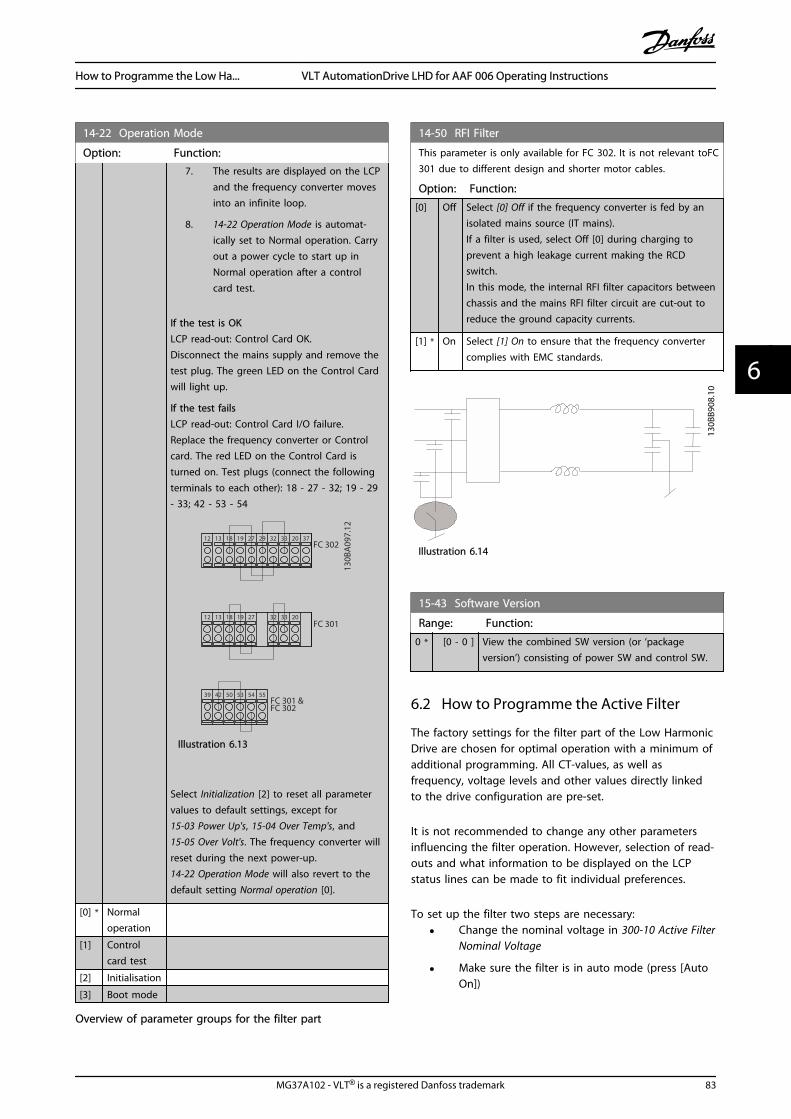
14-22 Operation Mode
Option: Function:7. The results are displayed on the LCP
and the frequency converter movesinto an infinite loop.
8. 14-22 Operation Mode is automat-ically set to Normal operation. Carryout a power cycle to start up inNormal operation after a controlcard test.
If the test is OKLCP read-out: Control Card OK.Disconnect the mains supply and remove thetest plug. The green LED on the Control Cardwill light up.
If the test failsLCP read-out: Control Card I/O failure.Replace the frequency converter or Controlcard. The red LED on the Control Card isturned on. Test plugs (connect the followingterminals to each other): 18 - 27 - 32; 19 - 29- 33; 42 - 53 - 54
130B
A09
7.12
FC 302
FC 301
FC 301 &FC 302
1312 18 37322719 29 33 20
5039 42 5453 55
191812 13 203327 32
Illustration 6.13
Select Initialization [2] to reset all parametervalues to default settings, except for15-03 Power Up's, 15-04 Over Temp's, and15-05 Over Volt's. The frequency converter willreset during the next power-up.14-22 Operation Mode will also revert to thedefault setting Normal operation [0].
[0] * Normaloperation
[1] Controlcard test
[2] Initialisation
[3] Boot mode
14-50 RFI Filter
This parameter is only available for FC 302. It is not relevant toFC301 due to different design and shorter motor cables.
Option: Function:
[0] Off Select [0] Off if the frequency converter is fed by anisolated mains source (IT mains).If a filter is used, select Off [0] during charging toprevent a high leakage current making the RCDswitch.In this mode, the internal RFI filter capacitors betweenchassis and the mains RFI filter circuit are cut-out toreduce the ground capacity currents.
[1] * On Select [1] On to ensure that the frequency convertercomplies with EMC standards.
130B
B908
.10
Illustration 6.14
15-43 Software Version
Range: Function:
0 * [0 - 0 ] View the combined SW version (or ‘packageversion’) consisting of power SW and control SW.
6.2 How to Programme the Active Filter
The factory settings for the filter part of the Low HarmonicDrive are chosen for optimal operation with a minimum ofadditional programming. All CT-values, as well asfrequency, voltage levels and other values directly linkedto the drive configuration are pre-set.
It is not recommended to change any other parametersinfluencing the filter operation. However, selection of read-outs and what information to be displayed on the LCPstatus lines can be made to fit individual preferences.
To set up the filter two steps are necessary:
• Change the nominal voltage in 300-10 Active FilterNominal Voltage
• Make sure the filter is in auto mode (press [AutoOn])
Overview of parameter groups for the filter part
How to Programme the Low Ha... VLT AutomationDrive LHD for AAF 006 Operating Instructions
MG37A102 - VLT® is a registered Danfoss trademark 83
6 6
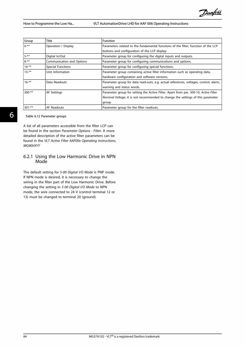
Group Title Function
0-** Operation / Display Parameters related to the fundamental functions of the filter, function of the LCPbuttons and configuration of the LCP display.
5-** Digital In/Out Parameter group for configuring the digital inputs and outputs.
8-** Communication and Options Parameter group for configuring communications and options.
14-** Special Functions Parameter group for configuring special functions.
15-** Unit Information Parameter group containing active filter information such as operating data,hardware configuration and software versions.
16-** Data Readouts Parameter group for data read-outs, e.g. actual references, voltages, control, alarm,warning and status words.
300-** AF Settings Parameter group for setting the Active Filter. Apart from par. 300-10, Active FilterNominal Voltage, it is not recommended to change the settings of this parametergroup
301-** AF Readouts Parameter group for the filter readouts.
Table 6.12 Parameter groups
A list of all parameters accessible from the filter LCP canbe found in the section Parameter Options - Filter. A moredetailed description of the active filter parameters can befound in the VLT Active Filter AAF00x Operating Instructions,MG90VXYY
6.2.1 Using the Low Harmonic Drive in NPNMode
The default setting for 5-00 Digital I/O Mode is PNP mode.If NPN mode is desired, it is necessary to change thewiring in the filter part of the Low Harmonic Drive. Beforechanging the setting in 5-00 Digital I/O Mode to NPNmode, the wire connected to 24 V (control terminal 12 or13) must be changed to terminal 20 (ground).
How to Programme the Low Ha... VLT AutomationDrive LHD for AAF 006 Operating Instructions
84 MG37A102 - VLT® is a registered Danfoss trademark
66
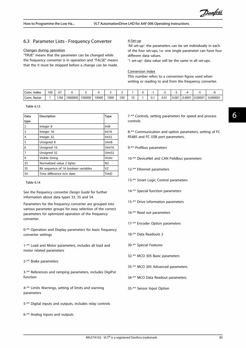
6.3 Parameter Lists - Frequency Converter
Changes during operation”TRUE” means that the parameter can be changed whilethe frequency converter is in operation and “FALSE” meansthat the it must be stopped before a change can be made.
4-Set-up'All set-up': the parameters can be set individually in eachof the four set-ups, i.e. one single parameter can have fourdifferent data values.’1 set-up’: data value will be the same in all set-ups.
Conversion indexThis number refers to a conversion figure used whenwriting or reading to and from the frequency converter.
Conv. index 100 67 6 5 4 3 2 1 0 -1 -2 -3 -4 -5 -6
Conv. factor 1 1/60 1000000 100000 10000 1000 100 10 1 0.1 0.01 0.001 0.0001 0.00001 0.000001
Table 6.13
Datatype
Description Type
2 Integer 8 Int8
3 Integer 16 Int16
4 Integer 32 Int32
5 Unsigned 8 Uint8
6 Unsigned 16 Uint16
7 Unsigned 32 Uint32
9 Visible String VisStr
33 Normalized value 2 bytes N2
35 Bit sequence of 16 boolean variables V2
54 Time difference w/o date TimD
Table 6.14
See the frequency converter Design Guide for furtherinformation about data types 33, 35 and 54.
Parameters for the frequency converter are grouped intovarious parameter groups for easy selection of the correctparameters for optimized operation of the frequencyconverter.
0-** Operation and Display parameters for basic frequencyconverter settings
1-** Load and Motor parameters, includes all load andmotor related parameters
2-** Brake parameters
3-** References and ramping parameters, includes DigiPotfunction
4-** Limits Warnings, setting of limits and warningparameters
5-** Digital inputs and outputs, includes relay controls
6-** Analog inputs and outputs
7-** Controls, setting parameters for speed and processcontrols
8-** Communication and option parameters, setting of FCRS485 and FC USB port parameters.
9-** Profibus parameters
10-** DeviceNet and CAN Fieldbus parameters
12-** Ethernet parameters
13-** Smart Logic Control parameters
14-** Special function parameters
15-** Drive information parameters
16-** Read out parameters
17-** Encoder Option parameters
18-** Data Readouts 2
30-** Special Features
32-** MCO 305 Basic parameters
33-** MCO 305 Advanced parameters
34-** MCO Data Readout parameters
35-** Sensor Input Option
How to Programme the Low Ha... VLT AutomationDrive LHD for AAF 006 Operating Instructions
MG37A102 - VLT® is a registered Danfoss trademark 85
6 6

6.3.1 0-** Operation/Display
Par.No. #
Parameter description Default value 4-set-up FC 302only
Changeduring
operation
Conver-sion index
Type
0-0* Basic Settings
0-01 Language [0] English 1 set-up TRUE - Uint8
0-02 Motor Speed Unit [0] RPM 2 set-ups FALSE - Uint8
0-03 Regional Settings [0] International 2 set-ups FALSE - Uint8
0-04 Operating State at Power-up (Hand) [1] Forced stop, ref=old All set-ups TRUE - Uint8
0-09 Performance Monitor 0.0 % All set-ups TRUE -1 Uint16
0-1* Set-up Operations
0-10 Active Set-up [1] Set-up 1 1 set-up TRUE - Uint8
0-11 Edit Set-up [1] Set-up 1 All set-ups TRUE - Uint8
0-12 This Set-up Linked to [0] Not linked All set-ups FALSE - Uint8
0-13 Readout: Linked Set-ups 0 N/A All set-ups FALSE 0 Uint16
0-14 Readout: Edit Set-ups / Channel 0 N/A All set-ups TRUE 0 Int32
0-15 Readout: actual setup 0 N/A All set-ups FALSE 0 Uint8
0-2* LCP Display
0-20 Display Line 1.1 Small 1617 All set-ups TRUE - Uint16
0-21 Display Line 1.2 Small 1614 All set-ups TRUE - Uint16
0-22 Display Line 1.3 Small 1610 All set-ups TRUE - Uint16
0-23 Display Line 2 Large 1613 All set-ups TRUE - Uint16
0-24 Display Line 3 Large 1602 All set-ups TRUE - Uint16
0-25 My Personal Menu App.Dependent 1 set-up TRUE 0 Uint16
0-3* LCP Custom Readout
0-30 Unit for User-defined Readout [0] None All set-ups TRUE - Uint8
0-31 Min Value of User-defined Readout 0.00 CustomReadoutUnit All set-ups TRUE -2 Int32
0-32 Max Value of User-defined Readout100.00 CustomRea-
doutUnit All set-ups TRUE -2 Int32
0-37 Display Text 1 0 N/A 1 set-up TRUE 0 VisStr[25]
0-38 Display Text 2 0 N/A 1 set-up TRUE 0 VisStr[25]
0-39 Display Text 3 0 N/A 1 set-up TRUE 0 VisStr[25]
0-4* LCP Keypad
0-40 [Hand on] Key on LCP null All set-ups TRUE - Uint8
0-41 [Off] Key on LCP null All set-ups TRUE - Uint8
0-42 [Auto on] Key on LCP null All set-ups TRUE - Uint8
0-43 [Reset] Key on LCP null All set-ups TRUE - Uint8
0-44 [Off/Reset] Key on LCP null All set-ups TRUE - Uint8
0-45 [Drive Bypass] Key on LCP null All set-ups TRUE - Uint8
0-5* Copy/Save
0-50 LCP Copy [0] No copy All set-ups FALSE - Uint8
0-51 Set-up Copy [0] No copy All set-ups FALSE - Uint8
0-6* Password
0-60 Main Menu Password 100 N/A 1 set-up TRUE 0 Int16
0-61 Access to Main Menu w/o Password [0] Full access 1 set-up TRUE - Uint8
0-65 Quick Menu Password 200 N/A 1 set-up TRUE 0 Int16
0-66 Access to Quick Menu w/o Password [0] Full access 1 set-up TRUE - Uint8
0-67 Bus Password Access 0 N/A All set-ups TRUE 0 Uint16
Table 6.15
How to Programme the Low Ha... VLT AutomationDrive LHD for AAF 006 Operating Instructions
86 MG37A102 - VLT® is a registered Danfoss trademark
66
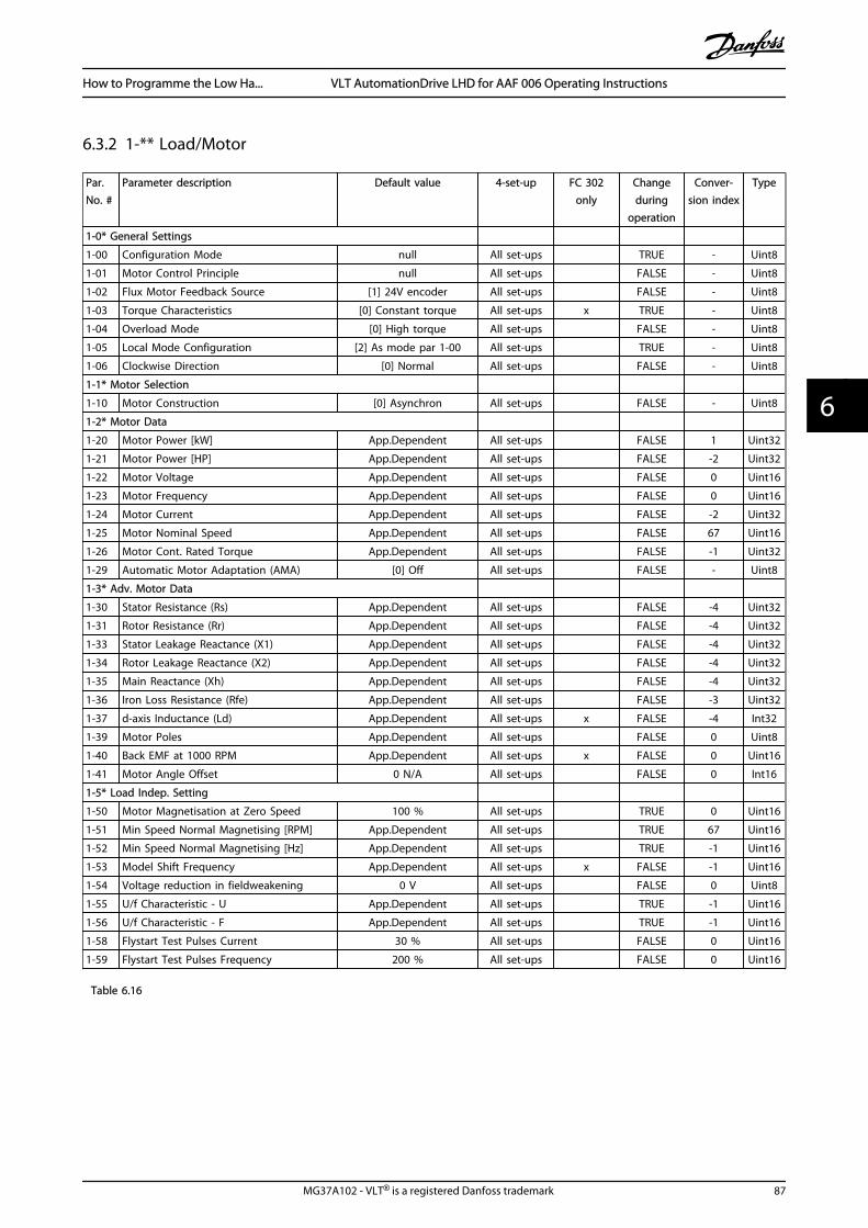
6.3.2 1-** Load/Motor
Par.No. #
Parameter description Default value 4-set-up FC 302only
Changeduring
operation
Conver-sion index
Type
1-0* General Settings
1-00 Configuration Mode null All set-ups TRUE - Uint8
1-01 Motor Control Principle null All set-ups FALSE - Uint8
1-02 Flux Motor Feedback Source [1] 24V encoder All set-ups FALSE - Uint8
1-03 Torque Characteristics [0] Constant torque All set-ups x TRUE - Uint8
1-04 Overload Mode [0] High torque All set-ups FALSE - Uint8
1-05 Local Mode Configuration [2] As mode par 1-00 All set-ups TRUE - Uint8
1-06 Clockwise Direction [0] Normal All set-ups FALSE - Uint8
1-1* Motor Selection
1-10 Motor Construction [0] Asynchron All set-ups FALSE - Uint8
1-2* Motor Data
1-20 Motor Power [kW] App.Dependent All set-ups FALSE 1 Uint32
1-21 Motor Power [HP] App.Dependent All set-ups FALSE -2 Uint32
1-22 Motor Voltage App.Dependent All set-ups FALSE 0 Uint16
1-23 Motor Frequency App.Dependent All set-ups FALSE 0 Uint16
1-24 Motor Current App.Dependent All set-ups FALSE -2 Uint32
1-25 Motor Nominal Speed App.Dependent All set-ups FALSE 67 Uint16
1-26 Motor Cont. Rated Torque App.Dependent All set-ups FALSE -1 Uint32
1-29 Automatic Motor Adaptation (AMA) [0] Off All set-ups FALSE - Uint8
1-3* Adv. Motor Data
1-30 Stator Resistance (Rs) App.Dependent All set-ups FALSE -4 Uint32
1-31 Rotor Resistance (Rr) App.Dependent All set-ups FALSE -4 Uint32
1-33 Stator Leakage Reactance (X1) App.Dependent All set-ups FALSE -4 Uint32
1-34 Rotor Leakage Reactance (X2) App.Dependent All set-ups FALSE -4 Uint32
1-35 Main Reactance (Xh) App.Dependent All set-ups FALSE -4 Uint32
1-36 Iron Loss Resistance (Rfe) App.Dependent All set-ups FALSE -3 Uint32
1-37 d-axis Inductance (Ld) App.Dependent All set-ups x FALSE -4 Int32
1-39 Motor Poles App.Dependent All set-ups FALSE 0 Uint8
1-40 Back EMF at 1000 RPM App.Dependent All set-ups x FALSE 0 Uint16
1-41 Motor Angle Offset 0 N/A All set-ups FALSE 0 Int16
1-5* Load Indep. Setting
1-50 Motor Magnetisation at Zero Speed 100 % All set-ups TRUE 0 Uint16
1-51 Min Speed Normal Magnetising [RPM] App.Dependent All set-ups TRUE 67 Uint16
1-52 Min Speed Normal Magnetising [Hz] App.Dependent All set-ups TRUE -1 Uint16
1-53 Model Shift Frequency App.Dependent All set-ups x FALSE -1 Uint16
1-54 Voltage reduction in fieldweakening 0 V All set-ups FALSE 0 Uint8
1-55 U/f Characteristic - U App.Dependent All set-ups TRUE -1 Uint16
1-56 U/f Characteristic - F App.Dependent All set-ups TRUE -1 Uint16
1-58 Flystart Test Pulses Current 30 % All set-ups FALSE 0 Uint16
1-59 Flystart Test Pulses Frequency 200 % All set-ups FALSE 0 Uint16
Table 6.16
How to Programme the Low Ha... VLT AutomationDrive LHD for AAF 006 Operating Instructions
MG37A102 - VLT® is a registered Danfoss trademark 87
6 6
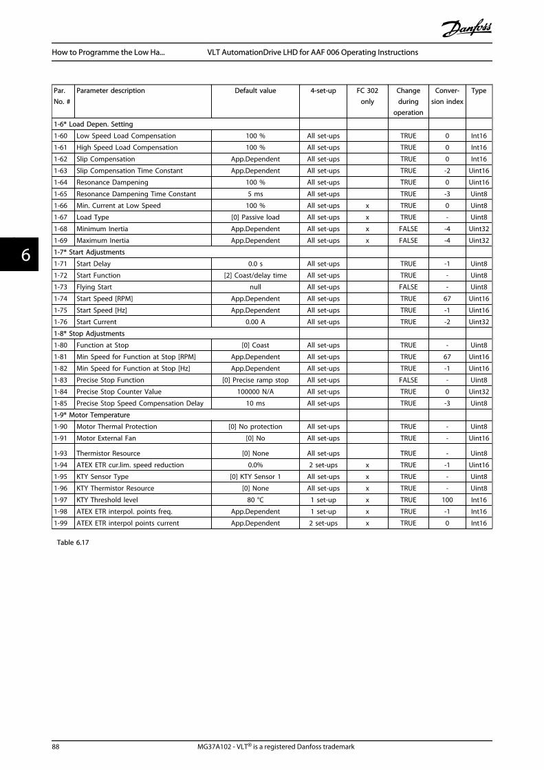
Par.No. #
Parameter description Default value 4-set-up FC 302only
Changeduring
operation
Conver-sion index
Type
1-6* Load Depen. Setting
1-60 Low Speed Load Compensation 100 % All set-ups TRUE 0 Int16
1-61 High Speed Load Compensation 100 % All set-ups TRUE 0 Int16
1-62 Slip Compensation App.Dependent All set-ups TRUE 0 Int16
1-63 Slip Compensation Time Constant App.Dependent All set-ups TRUE -2 Uint16
1-64 Resonance Dampening 100 % All set-ups TRUE 0 Uint16
1-65 Resonance Dampening Time Constant 5 ms All set-ups TRUE -3 Uint8
1-66 Min. Current at Low Speed 100 % All set-ups x TRUE 0 Uint8
1-67 Load Type [0] Passive load All set-ups x TRUE - Uint8
1-68 Minimum Inertia App.Dependent All set-ups x FALSE -4 Uint32
1-69 Maximum Inertia App.Dependent All set-ups x FALSE -4 Uint32
1-7* Start Adjustments
1-71 Start Delay 0.0 s All set-ups TRUE -1 Uint8
1-72 Start Function [2] Coast/delay time All set-ups TRUE - Uint8
1-73 Flying Start null All set-ups FALSE - Uint8
1-74 Start Speed [RPM] App.Dependent All set-ups TRUE 67 Uint16
1-75 Start Speed [Hz] App.Dependent All set-ups TRUE -1 Uint16
1-76 Start Current 0.00 A All set-ups TRUE -2 Uint32
1-8* Stop Adjustments
1-80 Function at Stop [0] Coast All set-ups TRUE - Uint8
1-81 Min Speed for Function at Stop [RPM] App.Dependent All set-ups TRUE 67 Uint16
1-82 Min Speed for Function at Stop [Hz] App.Dependent All set-ups TRUE -1 Uint16
1-83 Precise Stop Function [0] Precise ramp stop All set-ups FALSE - Uint8
1-84 Precise Stop Counter Value 100000 N/A All set-ups TRUE 0 Uint32
1-85 Precise Stop Speed Compensation Delay 10 ms All set-ups TRUE -3 Uint8
1-9* Motor Temperature
1-90 Motor Thermal Protection [0] No protection All set-ups TRUE - Uint8
1-91 Motor External Fan [0] No All set-ups TRUE - Uint16
1-93 Thermistor Resource [0] None All set-ups TRUE - Uint8
1-94 ATEX ETR cur.lim. speed reduction 0.0% 2 set-ups x TRUE -1 Uint16
1-95 KTY Sensor Type [0] KTY Sensor 1 All set-ups x TRUE - Uint8
1-96 KTY Thermistor Resource [0] None All set-ups x TRUE - Uint8
1-97 KTY Threshold level 80 °C 1 set-up x TRUE 100 Int16
1-98 ATEX ETR interpol. points freq. App.Dependent 1 set-up x TRUE -1 Int16
1-99 ATEX ETR interpol points current App.Dependent 2 set-ups x TRUE 0 Int16
Table 6.17
How to Programme the Low Ha... VLT AutomationDrive LHD for AAF 006 Operating Instructions
88 MG37A102 - VLT® is a registered Danfoss trademark
66
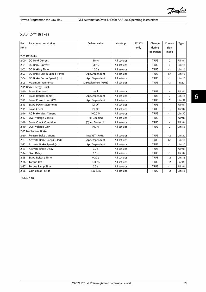
6.3.3 2-** Brakes
Par.No. #
Parameter description Default value 4-set-up FC 302only
Changeduring
operation
Conver-sion
index
Type
2-0* DC-Brake
2-00 DC Hold Current 50 % All set-ups TRUE 0 Uint8
2-01 DC Brake Current 50 % All set-ups TRUE 0 Uint16
2-02 DC Braking Time 10.0 s All set-ups TRUE -1 Uint16
2-03 DC Brake Cut In Speed [RPM] App.Dependent All set-ups TRUE 67 Uint16
2-04 DC Brake Cut In Speed [Hz] App.Dependent All set-ups TRUE -1 Uint16
2-05 Maximum Reference MaxReference (P303) All set-ups TRUE -3 Int32
2-1* Brake Energy Funct.
2-10 Brake Function null All set-ups TRUE - Uint8
2-11 Brake Resistor (ohm) App.Dependent All set-ups TRUE 0 Uint16
2-12 Brake Power Limit (kW) App.Dependent All set-ups TRUE 0 Uint32
2-13 Brake Power Monitoring [0] Off All set-ups TRUE - Uint8
2-15 Brake Check [0] Off All set-ups TRUE - Uint8
2-16 AC brake Max. Current 100.0 % All set-ups TRUE -1 Uint32
2-17 Over-voltage Control [0] Disabled All set-ups TRUE - Uint8
2-18 Brake Check Condition [0] At Power Up All set-ups TRUE - Uint8
2-19 Over-voltage Gain 100 % All set-ups TRUE 0 Uint16
2-2* Mechanical Brake
2-20 Release Brake Current ImaxVLT (P1637) All set-ups TRUE -2 Uint32
2-21 Activate Brake Speed [RPM] App.Dependent All set-ups TRUE 67 Uint16
2-22 Activate Brake Speed [Hz] App.Dependent All set-ups TRUE -1 Uint16
2-23 Activate Brake Delay 0.0 s All set-ups TRUE -1 Uint8
2-24 Stop Delay 0.0 s All set-ups TRUE -1 Uint8
2-25 Brake Release Time 0.20 s All set-ups TRUE -2 Uint16
2-26 Torque Ref 0.00 % All set-ups TRUE -2 Int16
2-27 Torque Ramp Time 0.2 s All set-ups TRUE -1 Uint8
2-28 Gain Boost Factor 1.00 N/A All set-ups TRUE -2 Uint16
Table 6.18
How to Programme the Low Ha... VLT AutomationDrive LHD for AAF 006 Operating Instructions
MG37A102 - VLT® is a registered Danfoss trademark 89
6 6
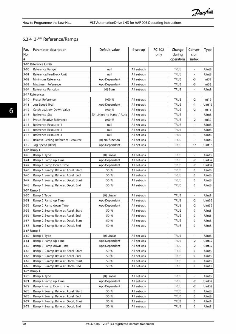
6.3.4 3-** Reference/Ramps
Par.No.#
Parameter description Default value 4-set-up FC 302only
Changeduring
operation
Conver-sion
index
Type
3-0* Reference Limits
3-00 Reference Range null All set-ups TRUE - Uint8
3-01 Reference/Feedback Unit null All set-ups TRUE - Uint8
3-02 Minimum Reference App.Dependent All set-ups TRUE -3 Int32
3-03 Maximum Reference App.Dependent All set-ups TRUE -3 Int32
3-04 Reference Function [0] Sum All set-ups TRUE - Uint8
3-1* References
3-10 Preset Reference 0.00 % All set-ups TRUE -2 Int16
3-11 Jog Speed [Hz] App.Dependent All set-ups TRUE -1 Uint16
3-12 Catch up/slow Down Value 0.00 % All set-ups TRUE -2 Int16
3-13 Reference Site [0] Linked to Hand / Auto All set-ups TRUE - Uint8
3-14 Preset Relative Reference 0.00 % All set-ups TRUE -2 Int32
3-15 Reference Resource 1 null All set-ups TRUE - Uint8
3-16 Reference Resource 2 null All set-ups TRUE - Uint8
3-17 Reference Resource 3 null All set-ups TRUE - Uint8
3-18 Relative Scaling Reference Resource [0] No function All set-ups TRUE - Uint8
3-19 Jog Speed [RPM] App.Dependent All set-ups TRUE 67 Uint16
3-4* Ramp 1
3-40 Ramp 1 Type [0] Linear All set-ups TRUE - Uint8
3-41 Ramp 1 Ramp up Time App.Dependent All set-ups TRUE -2 Uint32
3-42 Ramp 1 Ramp Down Time App.Dependent All set-ups TRUE -2 Uint32
3-45 Ramp 1 S-ramp Ratio at Accel. Start 50 % All set-ups TRUE 0 Uint8
3-46 Ramp 1 S-ramp Ratio at Accel. End 50 % All set-ups TRUE 0 Uint8
3-47 Ramp 1 S-ramp Ratio at Decel. Start 50 % All set-ups TRUE 0 Uint8
3-48 Ramp 1 S-ramp Ratio at Decel. End 50 % All set-ups TRUE 0 Uint8
3-5* Ramp 2
3-50 Ramp 2 Type [0] Linear All set-ups TRUE - Uint8
3-51 Ramp 2 Ramp up Time App.Dependent All set-ups TRUE -2 Uint32
3-52 Ramp 2 Ramp down Time App.Dependent All set-ups TRUE -2 Uint32
3-55 Ramp 2 S-ramp Ratio at Accel. Start 50 % All set-ups TRUE 0 Uint8
3-56 Ramp 2 S-ramp Ratio at Accel. End 50 % All set-ups TRUE 0 Uint8
3-57 Ramp 2 S-ramp Ratio at Decel. Start 50 % All set-ups TRUE 0 Uint8
3-58 Ramp 2 S-ramp Ratio at Decel. End 50 % All set-ups TRUE 0 Uint8
3-6* Ramp 3
3-60 Ramp 3 Type [0] Linear All set-ups TRUE - Uint8
3-61 Ramp 3 Ramp up Time App.Dependent All set-ups TRUE -2 Uint32
3-62 Ramp 3 Ramp down Time App.Dependent All set-ups TRUE -2 Uint32
3-65 Ramp 3 S-ramp Ratio at Accel. Start 50 % All set-ups TRUE 0 Uint8
3-66 Ramp 3 S-ramp Ratio at Accel. End 50 % All set-ups TRUE 0 Uint8
3-67 Ramp 3 S-ramp Ratio at Decel. Start 50 % All set-ups TRUE 0 Uint8
3-68 Ramp 3 S-ramp Ratio at Decel. End 50 % All set-ups TRUE 0 Uint8
3-7* Ramp 4
3-70 Ramp 4 Type [0] Linear All set-ups TRUE - Uint8
3-71 Ramp 4 Ramp up Time App.Dependent All set-ups TRUE -2 Uint32
3-72 Ramp 4 Ramp Down Time App.Dependent All set-ups TRUE -2 Uint32
3-75 Ramp 4 S-ramp Ratio at Accel. Start 50 % All set-ups TRUE 0 Uint8
3-76 Ramp 4 S-ramp Ratio at Accel. End 50 % All set-ups TRUE 0 Uint8
3-77 Ramp 4 S-ramp Ratio at Decel. Start 50 % All set-ups TRUE 0 Uint8
3-78 Ramp 4 S-ramp Ratio at Decel. End 50 % All set-ups TRUE 0 Uint8
How to Programme the Low Ha... VLT AutomationDrive LHD for AAF 006 Operating Instructions
90 MG37A102 - VLT® is a registered Danfoss trademark
66
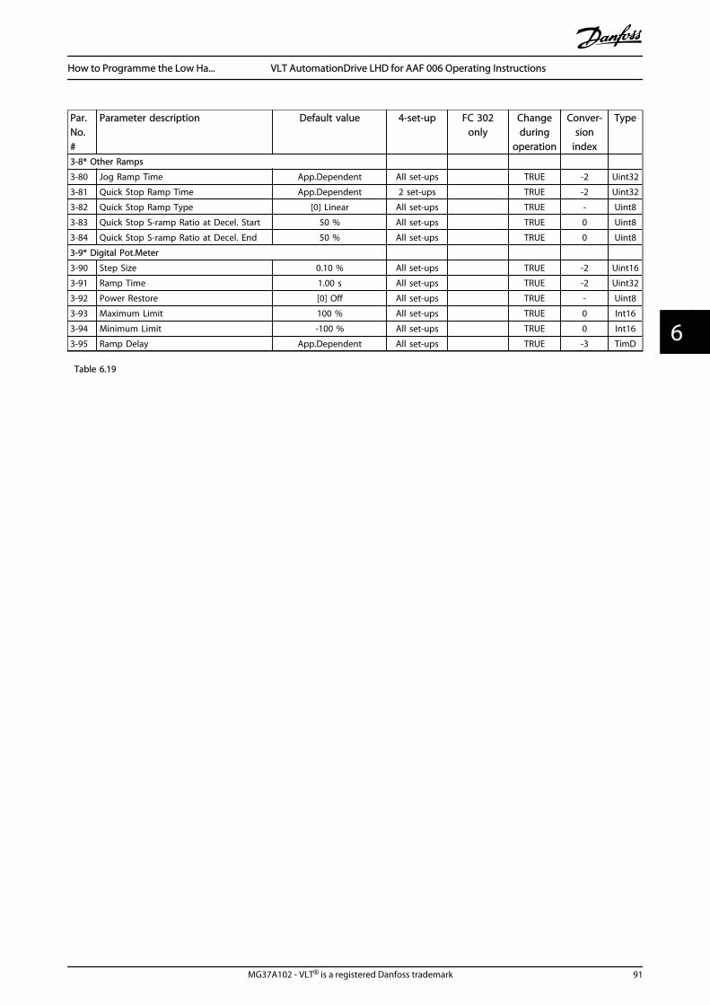
Par.No.#
Parameter description Default value 4-set-up FC 302only
Changeduring
operation
Conver-sion
index
Type
3-8* Other Ramps
3-80 Jog Ramp Time App.Dependent All set-ups TRUE -2 Uint32
3-81 Quick Stop Ramp Time App.Dependent 2 set-ups TRUE -2 Uint32
3-82 Quick Stop Ramp Type [0] Linear All set-ups TRUE - Uint8
3-83 Quick Stop S-ramp Ratio at Decel. Start 50 % All set-ups TRUE 0 Uint8
3-84 Quick Stop S-ramp Ratio at Decel. End 50 % All set-ups TRUE 0 Uint8
3-9* Digital Pot.Meter
3-90 Step Size 0.10 % All set-ups TRUE -2 Uint16
3-91 Ramp Time 1.00 s All set-ups TRUE -2 Uint32
3-92 Power Restore [0] Off All set-ups TRUE - Uint8
3-93 Maximum Limit 100 % All set-ups TRUE 0 Int16
3-94 Minimum Limit -100 % All set-ups TRUE 0 Int16
3-95 Ramp Delay App.Dependent All set-ups TRUE -3 TimD
Table 6.19
How to Programme the Low Ha... VLT AutomationDrive LHD for AAF 006 Operating Instructions
MG37A102 - VLT® is a registered Danfoss trademark 91
6 6

6.3.5 4-** Limits / Warnings
Par.No. #
Parameter description Default value 4-set-up FC 302only
Changeduring
operation
Conver-sion
index
Type
4-1* Motor Limits
4-10 Motor Speed Direction null All set-ups FALSE - Uint8
4-11 Motor Speed Low Limit [RPM] App.Dependent All set-ups TRUE 67 Uint16
4-12 Motor Speed Low Limit [Hz] App.Dependent All set-ups TRUE -1 Uint16
4-13 Motor Speed High Limit [RPM] App.Dependent All set-ups TRUE 67 Uint16
4-14 Motor Speed High Limit [Hz] App.Dependent All set-ups TRUE -1 Uint16
4-16 Torque Limit Motor Mode App.Dependent All set-ups TRUE -1 Uint16
4-17 Torque Limit Generator Mode 100.0 % All set-ups TRUE -1 Uint16
4-18 Current Limit App.Dependent All set-ups TRUE -1 Uint32
4-19 Max Output Frequency 132.0 Hz All set-ups FALSE -1 Uint16
4-2* Limit Factors
4-20 Torque Limit Factor Source [0] No function All set-ups TRUE - Uint8
4-21 Speed Limit Factor Source [0] No function All set-ups TRUE - Uint8
4-3* Motor Speed Mon.
4-30 Motor Feedback Loss Function [2] Trip All set-ups TRUE - Uint8
4-31 Motor Feedback Speed Error 300 RPM All set-ups TRUE 67 Uint16
4-32 Motor Feedback Loss Timeout 0.05 s All set-ups TRUE -2 Uint16
4-34 Tracking Error Function null All set-ups TRUE - Uint8
4-35 Tracking Error 10 RPM All set-ups TRUE 67 Uint16
4-36 Tracking Error Timeout 1.00 s All set-ups TRUE -2 Uint16
4-37 Tracking Error Ramping 100 RPM All set-ups TRUE 67 Uint16
4-38 Tracking Error Ramping Timeout 1.00 s All set-ups TRUE -2 Uint16
4-39 Tracking Error After Ramping Timeout 5.00 s All set-ups TRUE -2 Uint16
4-5* Adj. Warnings
4-50 Warning Current Low 0.00 A All set-ups TRUE -2 Uint32
4-51 Warning Current High ImaxVLT (P1637) All set-ups TRUE -2 Uint32
4-52 Warning Speed Low 0 RPM All set-ups TRUE 67 Uint16
4-53 Warning Speed HighoutputSpeedHighLimit
(P413) All set-ups TRUE 67 Uint16
4-54 Warning Reference Low -999999.999 N/A All set-ups TRUE -3 Int32
4-55 Warning Reference High 999999.999 N/A All set-ups TRUE -3 Int32
4-56 Warning Feedback Low-999999.999 Reference-
FeedbackUnit All set-ups TRUE -3 Int32
4-57 Warning Feedback High999999.999 Reference-
FeedbackUnit All set-ups TRUE -3 Int32
4-58 Missing Motor Phase Function null All set-ups TRUE - Uint8
4-6* Speed Bypass
4-60 Bypass Speed From [RPM] App.Dependent All set-ups TRUE 67 Uint16
4-61 Bypass Speed From [Hz] App.Dependent All set-ups TRUE -1 Uint16
4-62 Bypass Speed To [RPM] App.Dependent All set-ups TRUE 67 Uint16
4-63 Bypass Speed To [Hz] App.Dependent All set-ups TRUE -1 Uint16
Table 6.20
How to Programme the Low Ha... VLT AutomationDrive LHD for AAF 006 Operating Instructions
92 MG37A102 - VLT® is a registered Danfoss trademark
66

6.3.6 5-** Digital In/Out
Par.No. #
Parameter description Default value 4-set-up FC 302only
Changeduring
operation
Conver-sion
index
Type
5-0* Digital I/O mode
5-00 Digital I/O Mode [0] PNP All set-ups FALSE - Uint8
5-01 Terminal 27 Mode [0] Input All set-ups TRUE - Uint8
5-02 Terminal 29 Mode [0] Input All set-ups x TRUE - Uint8
5-1* Digital Inputs
5-10 Terminal 18 Digital Input null All set-ups TRUE - Uint8
5-11 Terminal 19 Digital Input null All set-ups TRUE - Uint8
5-12 Terminal 27 Digital Input null All set-ups TRUE - Uint8
5-13 Terminal 29 Digital Input null All set-ups x TRUE - Uint8
5-14 Terminal 32 Digital Input null All set-ups TRUE - Uint8
5-15 Terminal 33 Digital Input null All set-ups TRUE - Uint8
5-16 Terminal X30/2 Digital Input null All set-ups TRUE - Uint8
5-17 Terminal X30/3 Digital Input null All set-ups TRUE - Uint8
5-18 Terminal X30/4 Digital Input null All set-ups TRUE - Uint8
5-19 Terminal 37 Safe Stop [1] Safe Stop Alarm 1 set-up TRUE - Uint8
5-20 Terminal X46/1 Digital Input [0] No operation All set-ups TRUE - Uint8
5-21 Terminal X46/3 Digital Input [0] No operation All set-ups TRUE - Uint8
5-22 Terminal X46/5 Digital Input [0] No operation All set-ups TRUE - Uint8
5-23 Terminal X46/7 Digital Input [0] No operation All set-ups TRUE - Uint8
5-24 Terminal X46/9 Digital Input [0] No operation All set-ups TRUE - Uint8
5-25 Terminal X46/11 Digital Input [0] No operation All set-ups TRUE - Uint8
5-26 Terminal X46/13 Digital Input [0] No operation All set-ups TRUE - Uint8
5-3* Digital Outputs
5-30 Terminal 27 Digital Output null All set-ups TRUE - Uint8
5-31 Terminal 29 Digital Output null All set-ups x TRUE - Uint8
5-32 Term X30/6 Digi Out (MCB 101) null All set-ups TRUE - Uint8
5-33 Term X30/7 Digi Out (MCB 101) null All set-ups TRUE - Uint8
5-4* Relays
5-40 Function Relay null All set-ups TRUE - Uint8
5-41 On Delay, Relay 0.01 s All set-ups TRUE -2 Uint16
5-42 Off Delay, Relay 0.01 s All set-ups TRUE -2 Uint16
5-5* Pulse Input
5-50 Term. 29 Low Frequency 100 Hz All set-ups x TRUE 0 Uint32
5-51 Term. 29 High Frequency 100 Hz All set-ups x TRUE 0 Uint32
5-52 Term. 29 Low Ref./Feedb. Value0.000 ReferenceFeed-
backUnit All set-ups x TRUE -3 Int32
5-53 Term. 29 High Ref./Feedb. Value App.Dependent All set-ups x TRUE -3 Int32
5-54 Pulse Filter Time Constant #29 100 ms All set-ups x FALSE -3 Uint16
5-55 Term. 33 Low Frequency 100 Hz All set-ups TRUE 0 Uint32
5-56 Term. 33 High Frequency 100 Hz All set-ups TRUE 0 Uint32
5-57 Term. 33 Low Ref./Feedb. Value0.000 ReferenceFeed-
backUnit All set-ups TRUE -3 Int32
5-58 Term. 33 High Ref./Feedb. Value App.Dependent All set-ups TRUE -3 Int32
5-59 Pulse Filter Time Constant #33 100 ms All set-ups FALSE -3 Uint16
Table 6.21
How to Programme the Low Ha... VLT AutomationDrive LHD for AAF 006 Operating Instructions
MG37A102 - VLT® is a registered Danfoss trademark 93
6 6

Par.No. #
Parameter description Default value 4-set-up FC 302only
Changeduring
operation
Conver-sion
index
Type
5-6* Pulse Output
5-60 Terminal 27 Pulse Output Variable null All set-ups TRUE - Uint8
5-62 Pulse Output Max Freq #27 App.Dependent All set-ups TRUE 0 Uint32
5-63 Terminal 29 Pulse Output Variable null All set-ups x TRUE - Uint8
5-65 Pulse Output Max Freq #29 App.Dependent All set-ups x TRUE 0 Uint32
5-66 Terminal X30/6 Pulse Output Variable null All set-ups TRUE - Uint8
5-68 Pulse Output Max Freq #X30/6 App.Dependent All set-ups TRUE 0 Uint32
5-7* 24V Encoder Input
5-70 Term 32/33 Pulses per Revolution 1024 N/A All set-ups FALSE 0 Uint16
5-71 Term 32/33 Encoder Direction [0] Clockwise All set-ups FALSE - Uint8
5-8* I/O Options
5-80 AHF Cap Reconnect Delay 25s 2 set-ups TRUE 0 Uint16
5-9* Bus Controlled
5-90 Digital & Relay Bus Control 0 N/A All set-ups TRUE 0 Uint32
5-93 Pulse Out #27 Bus Control 0.00 % All set-ups TRUE -2 N2
5-94 Pulse Out #27 Timeout Preset 0.00 % 1 set-up TRUE -2 Uint16
5-95 Pulse Out #29 Bus Control 0.00 % All set-ups x TRUE -2 N2
5-96 Pulse Out #29 Timeout Preset 0.00 % 1 set-up x TRUE -2 Uint16
5-97 Pulse Out #X30/6 Bus Control 0.00 % All set-ups TRUE -2 N2
5-98 Pulse Out #X30/6 Timeout Preset 0.00 % 1 set-up TRUE -2 Uint16
Table 6.22
How to Programme the Low Ha... VLT AutomationDrive LHD for AAF 006 Operating Instructions
94 MG37A102 - VLT® is a registered Danfoss trademark
66

6.3.7 6-** Analog In/Out
Par.No. #
Parameter description Default value 4-set-up FC 302only
Changeduring
operation
Conver-sion
index
Type
6-0* Analog I/O Mode
6-00 Live Zero Timeout Time 10 s All set-ups TRUE 0 Uint8
6-01 Live Zero Timeout Function [0] Off All set-ups TRUE - Uint8
6-1* Analog Input 1
6-10 Terminal 53 Low Voltage 0.07 V All set-ups TRUE -2 Int16
6-11 Terminal 53 High Voltage 10.00 V All set-ups TRUE -2 Int16
6-12 Terminal 53 Low Current 0.14 mA All set-ups TRUE -5 Int16
6-13 Terminal 53 High Current 20.00 mA All set-ups TRUE -5 Int16
6-14 Terminal 53 Low Ref./Feedb. Value 0 ReferenceFeedbackUnit All set-ups TRUE -3 Int32
6-15 Terminal 53 High Ref./Feedb. Value App.Dependent All set-ups TRUE -3 Int32
6-16 Terminal 53 Filter Time Constant 0.001 s All set-ups TRUE -3 Uint16
6-2* Analog Input 2
6-20 Terminal 54 Low Voltage 0.07 V All set-ups TRUE -2 Int16
6-21 Terminal 54 High Voltage 10.00 V All set-ups TRUE -2 Int16
6-22 Terminal 54 Low Current 0.14 mA All set-ups TRUE -5 Int16
6-23 Terminal 54 High Current 20.00 mA All set-ups TRUE -5 Int16
6-24 Terminal 54 Low Ref./Feedb. Value 0 ReferenceFeedbackUnit All set-ups TRUE -3 Int32
6-25 Terminal 54 High Ref./Feedb. Value App.Dependent All set-ups TRUE -3 Int32
6-26 Terminal 54 Filter Time Constant 0.001 s All set-ups TRUE -3 Uint16
6-3* Analog Input 3
6-30 Terminal X30/11 Low Voltage 0.07 V All set-ups TRUE -2 Int16
6-31 Terminal X30/11 High Voltage 10.00 V All set-ups TRUE -2 Int16
6-34 Term. X30/11 Low Ref./Feedb. Value 0 ReferenceFeedbackUnit All set-ups TRUE -3 Int32
6-35 Term. X30/11 High Ref./Feedb. Value App.Dependent All set-ups TRUE -3 Int32
6-36 Term. X30/11 Filter Time Constant 0.001 s All set-ups TRUE -3 Uint16
6-4* Analog Input 4
6-40 Terminal X30/12 Low Voltage 0.07 V All set-ups TRUE -2 Int16
6-41 Terminal X30/12 High Voltage 10.00 V All set-ups TRUE -2 Int16
6-44 Term. X30/12 Low Ref./Feedb. Value 0 ReferenceFeedbackUnit All set-ups TRUE -3 Int32
6-45 Term. X30/12 High Ref./Feedb. Value App.Dependent All set-ups TRUE -3 Int32
6-46 Term. X30/12 Filter Time Constant 0.001 s All set-ups TRUE -3 Uint16
6-5* Analog Output 1
6-50 Terminal 42 Output null All set-ups TRUE - Uint8
6-51 Terminal 42 Output Min Scale 0.00 % All set-ups TRUE -2 Int16
6-52 Terminal 42 Output Max Scale 100.00 % All set-ups TRUE -2 Int16
6-53 Term 42 Output Bus Ctrl 0.00 % All set-ups TRUE -2 N2
6-54 Terminal 42 Output Timeout Preset 0.00 % 1 set-up TRUE -2 Uint16
6-55 Analog Output Filter [0] Off 1 set-up TRUE - Uint8
6-6* Analog Output 2
6-60 Terminal X30/8 Output null All set-ups TRUE - Uint8
6-61 Terminal X30/8 Min. Scale 0.00 % All set-ups TRUE -2 Int16
6-62 Terminal X30/8 Max. Scale 100.00 % All set-ups TRUE -2 Int16
6-63 Terminal X30/8 Bus Control 0.00 % All set-ups TRUE -2 N2
6-64 Terminal X30/8 Output Timeout Preset 0.00 % 1 set-up TRUE -2 Uint16
Table 6.23
How to Programme the Low Ha... VLT AutomationDrive LHD for AAF 006 Operating Instructions
MG37A102 - VLT® is a registered Danfoss trademark 95
6 6
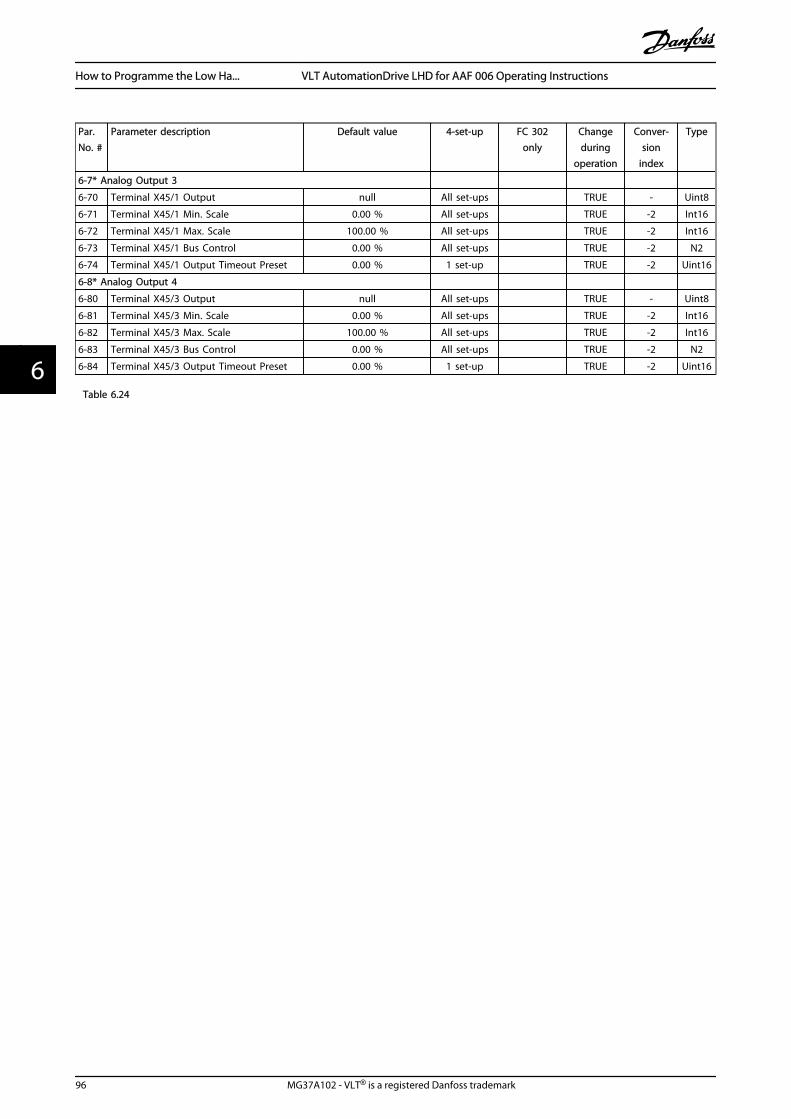
Par.No. #
Parameter description Default value 4-set-up FC 302only
Changeduring
operation
Conver-sion
index
Type
6-7* Analog Output 3
6-70 Terminal X45/1 Output null All set-ups TRUE - Uint8
6-71 Terminal X45/1 Min. Scale 0.00 % All set-ups TRUE -2 Int16
6-72 Terminal X45/1 Max. Scale 100.00 % All set-ups TRUE -2 Int16
6-73 Terminal X45/1 Bus Control 0.00 % All set-ups TRUE -2 N2
6-74 Terminal X45/1 Output Timeout Preset 0.00 % 1 set-up TRUE -2 Uint16
6-8* Analog Output 4
6-80 Terminal X45/3 Output null All set-ups TRUE - Uint8
6-81 Terminal X45/3 Min. Scale 0.00 % All set-ups TRUE -2 Int16
6-82 Terminal X45/3 Max. Scale 100.00 % All set-ups TRUE -2 Int16
6-83 Terminal X45/3 Bus Control 0.00 % All set-ups TRUE -2 N2
6-84 Terminal X45/3 Output Timeout Preset 0.00 % 1 set-up TRUE -2 Uint16
Table 6.24
How to Programme the Low Ha... VLT AutomationDrive LHD for AAF 006 Operating Instructions
96 MG37A102 - VLT® is a registered Danfoss trademark
66

6.3.8 7-** Controllers
Par.No. #
Parameter description Default value 4-set-up FC 302only
Changeduring
operation
Conver-sion
index
Type
7-0* Speed PID Ctrl.
7-00 Speed PID Feedback Source null All set-ups FALSE - Uint8
7-02 Speed PID Proportional Gain App.Dependent All set-ups TRUE -3 Uint16
7-03 Speed PID Integral Time App.Dependent All set-ups TRUE -4 Uint32
7-04 Speed PID Differentiation Time App.Dependent All set-ups TRUE -4 Uint16
7-05 Speed PID Diff. Gain Limit 5.0 N/A All set-ups TRUE -1 Uint16
7-06 Speed PID Lowpass Filter Time App.Dependent All set-ups TRUE -4 Uint16
7-07 Speed PID Feedback Gear Ratio 1.0000 N/A All set-ups FALSE -4 Uint32
7-08 Speed PID Feed Forward Factor 0 % All set-ups FALSE 0 Uint16
7-09 Speed PID Error Correction w/ Ramp 300RPM All set-ups TRUE 67 Uint32
7-1* Torque PI Ctrl.
7-12 Torque PI Proportional Gain 100 % All set-ups TRUE 0 Uint16
7-13 Torque PI Integration Time 0.020 s All set-ups TRUE -3 Uint16
7-2* Process Ctrl. Feedb
7-20 Process CL Feedback 1 Resource [0] No function All set-ups TRUE - Uint8
7-22 Process CL Feedback 2 Resource [0] No function All set-ups TRUE - Uint8
7-3* Process PID Ctrl.
7-30 Process PID Normal/ Inverse Control [0] Normal All set-ups TRUE - Uint8
7-31 Process PID Anti Windup [1] On All set-ups TRUE - Uint8
7-32 Process PID Start Speed 0 RPM All set-ups TRUE 67 Uint16
7-33 Process PID Proportional Gain 0.01 N/A All set-ups TRUE -2 Uint16
7-34 Process PID Integral Time 10000.00 s All set-ups TRUE -2 Uint32
7-35 Process PID Differentiation Time 0.00 s All set-ups TRUE -2 Uint16
7-36 Process PID Diff. Gain Limit 5.0 N/A All set-ups TRUE -1 Uint16
7-38 Process PID Feed Forward Factor 0 % All set-ups TRUE 0 Uint16
7-39 On Reference Bandwidth 5 % All set-ups TRUE 0 Uint8
7-4* Adv. Process PID I
7-40 Process PID I-part Reset [0] No All set-ups TRUE - Uint8
7-41 Process PID Output Neg. Clamp -100 % All set-ups TRUE 0 Int16
7-42 Process PID Output Pos. Clamp 100 % All set-ups TRUE 0 Int16
7-43 Process PID Gain Scale at Min. Ref. 100 % All set-ups TRUE 0 Int16
7-44 Process PID Gain Scale at Max. Ref. 100 % All set-ups TRUE 0 Int16
7-45 Process PID Feed Fwd Resource [0] No function All set-ups TRUE - Uint8
7-46 Process PID Feed Fwd Normal/ Inv. Ctrl. [0] Normal All set-ups TRUE - Uint8
7-48 PCD Feed Forward 0 N/A All set-ups x TRUE 0 Uint16
7-49 Process PID Output Normal/ Inv. Ctrl. [0] Normal All set-ups TRUE - Uint8
7-5* Adv. Process PID II
7-50 Process PID Extended PID [1] Enabled All set-ups TRUE - Uint8
7-51 Process PID Feed Fwd Gain 1.00 N/A All set-ups TRUE -2 Uint16
7-52 Process PID Feed Fwd Ramp up 0.01 s All set-ups TRUE -2 Uint32
7-53 Process PID Feed Fwd Ramp down 0.01 s All set-ups TRUE -2 Uint32
7-56 Process PID Ref. Filter Time 0.001 s All set-ups TRUE -3 Uint16
7-57 Process PID Fb. Filter Time 0.001 s All set-ups TRUE -3 Uint16
Table 6.25
How to Programme the Low Ha... VLT AutomationDrive LHD for AAF 006 Operating Instructions
MG37A102 - VLT® is a registered Danfoss trademark 97
6 6

6.3.9 8-** Comm. and Options
Par.No. #
Parameter description Default value 4-set-up FC 302only
Changeduring
operation
Conver-sion
index
Type
8-0* General Settings
8-01 Control Site [0] Digital and ctrl.word All set-ups TRUE - Uint8
8-02 Control Word Source null All set-ups TRUE - Uint8
8-03 Control Word Timeout Time 1.0 s 1 set-up TRUE -1 Uint32
8-04 Control Word Timeout Function null 1 set-up TRUE - Uint8
8-05 End-of-Timeout Function [1] Resume set-up 1 set-up TRUE - Uint8
8-06 Reset Control Word Timeout [0] Do not reset All set-ups TRUE - Uint8
8-07 Diagnosis Trigger [0] Disable 2 set-ups TRUE - Uint8
8-08 Readout Filtering null All set-ups TRUE - Uint8
8-1* Ctrl. Word Settings
8-10 Control Word Profile [0] FC profile All set-ups TRUE - Uint8
8-13 Configurable Status Word STW null All set-ups TRUE - Uint8
8-14 Configurable Control Word CTW [1] Profile default All set-ups TRUE - Uint8
8-3* FC Port Settings
8-30 Protocol [0] FC 1 set-up TRUE - Uint8
8-31 Address 1 N/A 1 set-up TRUE 0 Uint8
8-32 FC Port Baud Rate null 1 set-up TRUE - Uint8
8-33 Parity / Stop Bits [0] Even Parity, 1 Stop Bit 1 set-up TRUE - Uint8
8-34 Estimated cycle time 0 ms 2 set-ups TRUE -3 Uint32
8-35 Minimum Response Delay 10 ms All set-ups TRUE -3 Uint16
8-36 Max Response Delay App.Dependent 1 set-up TRUE -3 Uint16
8-37 Max Inter-Char Delay App.Dependent 1 set-up TRUE -5 Uint16
8-4* FC MC protocol set
8-40 Telegram selection [1] Standard telegram 1 2 set-ups TRUE - Uint8
8-41 Parameters for signals 0 All set-ups FALSE - Uint16
8-42 PCD write configuration App.Dependent All set-ups TRUE - Uint16
8-43 PCD read configuration App.Dependent All set-ups TRUE - Uint16
8-5* Digital/Bus
8-50 Coasting Select [3] Logic OR All set-ups TRUE - Uint8
8-51 Quick Stop Select [3] Logic OR All set-ups TRUE - Uint8
8-52 DC Brake Select [3] Logic OR All set-ups TRUE - Uint8
8-53 Start Select [3] Logic OR All set-ups TRUE - Uint8
8-54 Reversing Select [3] Logic OR All set-ups TRUE - Uint8
8-55 Set-up Select [3] Logic OR All set-ups TRUE - Uint8
8-56 Preset Reference Select [3] Logic OR All set-ups TRUE - Uint8
8-57 Profidrive OFF2 Select [3] Logic OR All set-ups TRUE - Uint8
8-58 Profidrive OFF3 Select [3] Logic OR All set-ups TRUE - Uint8
8-8* FC Port Diagnostics
8-80 Bus Message Count 0 N/A All set-ups TRUE 0 Uint32
8-81 Bus Error Count 0 N/A All set-ups TRUE 0 Uint32
8-82 Slave Messages Rcvd 0 N/A All set-ups TRUE 0 Uint32
8-83 Slave Error Count 0 N/A All set-ups TRUE 0 Uint32
8-9* Bus Jog
8-90 Bus Jog 1 Speed 100 RPM All set-ups TRUE 67 Uint16
8-91 Bus Jog 2 Speed App.Dependent All set-ups TRUE 67 Uint16
Table 6.26
How to Programme the Low Ha... VLT AutomationDrive LHD for AAF 006 Operating Instructions
98 MG37A102 - VLT® is a registered Danfoss trademark
66

6.3.10 9-** Profibus
Par.No. #
Parameter description Default value 4-set-up FC 302only
Changeduring
operation
Conver-sion
index
Type
9-00 Setpoint 0 N/A All set-ups TRUE 0 Uint16
9-07 Actual Value 0 N/A All set-ups FALSE 0 Uint16
9-15 PCD Write Configuration App.Dependent 1 set-up TRUE - Uint16
9-16 PCD Read Configuration App.Dependent 2 set-ups TRUE - Uint16
9-18 Node Address 126 N/A 1 set-up TRUE 0 Uint8
9-22 Telegram Selection [100] None 1 set-up TRUE - Uint8
9-23 Parameters for Signals 0 All set-ups TRUE - Uint16
9-27 Parameter Edit [1] Enabled 2 set-ups FALSE - Uint16
9-28 Process Control [1] Enable cyclic master 2 set-ups FALSE - Uint8
9-44 Fault Message Counter 0 N/A All set-ups TRUE 0 Uint16
9-45 Fault Code 0 N/A All set-ups TRUE 0 Uint16
9-47 Fault Number 0 N/A All set-ups TRUE 0 Uint16
9-52 Fault Situation Counter 0 N/A All set-ups TRUE 0 Uint16
9-53 Profibus Warning Word 0 N/A All set-ups TRUE 0 V2
9-63 Actual Baud Rate [255] No baudrate found All set-ups TRUE - Uint8
9-64 Device Identification 0 N/A All set-ups TRUE 0 Uint16
9-65 Profile Number 0 N/A All set-ups TRUE 0OctStr[
2]
9-67 Control Word 1 0 N/A All set-ups TRUE 0 V2
9-68 Status Word 1 0 N/A All set-ups TRUE 0 V2
9-71 Profibus Save Data Values [0] Off All set-ups TRUE - Uint8
9-72 ProfibusDriveReset [0] No action 1 set-up FALSE - Uint8
9-75 DO Identification 0 N/A All set-ups TRUE 0 Uint16
9-80 Defined Parameters (1) 0 N/A All set-ups FALSE 0 Uint16
9-81 Defined Parameters (2) 0 N/A All set-ups FALSE 0 Uint16
9-82 Defined Parameters (3) 0 N/A All set-ups FALSE 0 Uint16
9-83 Defined Parameters (4) 0 N/A All set-ups FALSE 0 Uint16
9-84 Defined Parameters (5) 0 N/A All set-ups FALSE 0 Uint16
9-90 Changed Parameters (1) 0 N/A All set-ups FALSE 0 Uint16
9-91 Changed Parameters (2) 0 N/A All set-ups FALSE 0 Uint16
9-92 Changed Parameters (3) 0 N/A All set-ups FALSE 0 Uint16
9-93 Changed parameters (4) 0 N/A All set-ups FALSE 0 Uint16
9-94 Changed parameters (5) 0 N/A All set-ups FALSE 0 Uint16
9-99 Profibus Revision Counter 0 N/A All set-ups TRUE 0 Uint16
Table 6.27
How to Programme the Low Ha... VLT AutomationDrive LHD for AAF 006 Operating Instructions
MG37A102 - VLT® is a registered Danfoss trademark 99
6 6

6.3.11 10-** CAN Fieldbus
Par.No. #
Parameter description Default value 4-set-up FC 302only
Changeduring
operation
Conver-sion
index
Type
10-0* Common Settings
10-00 CAN Protocol null 2 set-ups FALSE - Uint8
10-01 Baud Rate Select null 2 set-ups TRUE - Uint8
10-02 MAC ID App.Dependent 2 set-ups TRUE 0 Uint8
10-05 Readout Transmit Error Counter 0 N/A All set-ups TRUE 0 Uint8
10-06 Readout Receive Error Counter 0 N/A All set-ups TRUE 0 Uint8
10-07 Readout Bus Off Counter 0 N/A All set-ups TRUE 0 Uint8
10-1* DeviceNet
10-10 Process Data Type Selection null All set-ups TRUE - Uint8
10-11 Process Data Config Write App.Dependent All set-ups TRUE - Uint16
10-12 Process Data Config Read App.Dependent All set-ups TRUE - Uint16
10-13 Warning Parameter 0 N/A All set-ups TRUE 0 Uint16
10-14 Net Reference [0] Off 2 set-ups TRUE - Uint8
10-15 Net Control [0] Off 2 set-ups TRUE - Uint8
10-2* COS Filters
10-20 COS Filter 1 0 N/A All set-ups FALSE 0 Uint16
10-21 COS Filter 2 0 N/A All set-ups FALSE 0 Uint16
10-22 COS Filter 3 0 N/A All set-ups FALSE 0 Uint16
10-23 COS Filter 4 0 N/A All set-ups FALSE 0 Uint16
10-3* Parameter Access
10-30 Array Index 0 N/A 2 set-ups TRUE 0 Uint8
10-31 Store Data Values [0] Off All set-ups TRUE - Uint8
10-32 Devicenet Revision App.Dependent All set-ups TRUE 0 Uint16
10-33 Store Always [0] Off 1 set-up TRUE - Uint8
10-34 DeviceNet Product Code App.Dependent 1 set-up TRUE 0 Uint16
10-39 Devicenet F Parameters 0 N/A All set-ups TRUE 0 Uint32
10-5* CANopen
10-50 Process Data Config Write. App.Dependent 2 set-ups TRUE - Uint16
10-51 Process Data Config Read. App.Dependent 2 set-ups TRUE - Uint16
Table 6.28
How to Programme the Low Ha... VLT AutomationDrive LHD for AAF 006 Operating Instructions
100 MG37A102 - VLT® is a registered Danfoss trademark
66
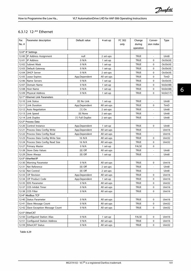
6.3.12 12-** Ethernet
Par.No. #
Parameter description Default value 4-set-up FC 302only
Changeduring
operation
Conver-sion index
Type
12-0* IP Settings
12-00 IP Address Assignment null 2 set-ups TRUE - Uint8
12-01 IP Address 0 N/A 1 set-up TRUE 0 OctStr[4]
12-02 Subnet Mask 0 N/A 1 set-up TRUE 0 OctStr[4]
12-03 Default Gateway 0 N/A 1 set-up TRUE 0 OctStr[4]
12-04 DHCP Server 0 N/A 2 set-ups TRUE 0 OctStr[4]
12-05 Lease Expires App.Dependent All set-ups TRUE 0 TimD
12-06 Name Servers 0 N/A 1 set-up TRUE 0 OctStr[4]
12-07 Domain Name 0 N/A 1 set-up TRUE 0 VisStr[48]
12-08 Host Name 0 N/A 1 set-up TRUE 0 VisStr[48]
12-09 Physical Address 0 N/A 1 set-up TRUE 0 VisStr[17]
12-1* Ethernet Link Parameters
12-10 Link Status [0] No Link 1 set-up TRUE - Uint8
12-11 Link Duration App.Dependent All set-ups TRUE 0 TimD
12-12 Auto Negotiation [1] On 2 set-ups TRUE - Uint8
12-13 Link Speed [0] None 2 set-ups TRUE - Uint8
12-14 Link Duplex [1] Full Duplex 2 set-ups TRUE - Uint8
12-2* Process Data
12-20 Control Instance App.Dependent 1 set-up TRUE 0 Uint8
12-21 Process Data Config Write App.Dependent All set-ups TRUE - Uint16
12-22 Process Data Config Read App.Dependent All set-ups TRUE - Uint16
12-23 Process Data Config Write Size 16 N/A All set-ups TRUE 0 Uint32
12-24 Process Data Config Read Size 16 N/A All set-ups TRUE 0 Uint32
12-27 Primary Master 0 N/A 1 set-up FALSE 0
12-28 Store Data Values [0] Off All set-ups TRUE - Uint8
12-29 Store Always [0] Off 1 set-up TRUE - Uint8
12-3* EtherNet/IP
12-30 Warning Parameter 0 N/A All set-ups TRUE 0 Uint16
12-31 Net Reference [0] Off 2 set-ups TRUE - Uint8
12-32 Net Control [0] Off 2 set-ups TRUE - Uint8
12-33 CIP Revision App.Dependent All set-ups TRUE 0 Uint16
12-34 CIP Product Code App.Dependent 1 set-up TRUE 0 Uint16
12-35 EDS Parameter 0 N/A All set-ups TRUE 0 Uint32
12-37 COS Inhibit Timer 0 N/A All set-ups TRUE 0 Uint16
12-38 COS Filter 0 N/A All set-ups TRUE 0 Uint16
12-4* Modbus TCP
12-40 Status Parameter 0 N/A All set-ups TRUE 0 Uint16
12-41 Slave Message Count 0 N/A All set-ups TRUE 0 Uint32
12-42 Slave Exception Message Count 0 N/A All set-ups TRUE 0 Uint32
12-5* EtherCAT
12-50 Configured Station Alias 0 N/A 1 set-up FALSE 0 Uint16
12-51 Configured Station Address 0 N/A All set-ups TRUE 0 Uint16
12-59 EtherCAT Status 0 N/A All set-ups TRUE 0 Uint32
Table 6.29
How to Programme the Low Ha... VLT AutomationDrive LHD for AAF 006 Operating Instructions
MG37A102 - VLT® is a registered Danfoss trademark 101
6 6

Par.No. #
Parameter description Default value 4-set-up FC 302only
Changeduring
operation
Conver-sion index
Type
12-8* Other Ethernet Services
12-80 FTP Server [0] Disabled 2 set-ups TRUE - Uint8
12-81 HTTP Server [0] Disabled 2 set-ups TRUE - Uint8
12-82 SMTP Service [0] Disabled 2 set-ups TRUE - Uint8
12-89 Transparent Socket Channel Port App.Dependent 2 set-ups TRUE 0 Uint16
12-9* Advanced Ethernet Services
12-90 Cable Diagnostic [0] Disabled 2 set-ups TRUE - Uint8
12-91 MDI-X [1] Enabled 2 set-ups TRUE - Uint8
12-92 IGMP Snooping [1] Enabled 2 set-ups TRUE - Uint8
12-93 Cable Error Length 0 N/A 1 set-up TRUE 0 Uint16
12-94 Broadcast Storm Protection -1 % 2 set-ups TRUE 0 Int8
12-95 Broadcast Storm Filter [0] Broadcast only 2 set-ups TRUE - Uint8
12-96 Port Mirroring null 2 set-ups TRUE - Uint8
12-98 Interface Counters 4000 N/A All set-ups TRUE 0 Uint32
12-99 Media Counters 0 N/A All set-ups TRUE 0 Uint32
Table 6.30
How to Programme the Low Ha... VLT AutomationDrive LHD for AAF 006 Operating Instructions
102 MG37A102 - VLT® is a registered Danfoss trademark
66

6.3.13 13-** Smart Logic
Par.No. #
Parameter description Default value 4-set-up FC 302only
Changeduring
operation
Conver-sion
index
Type
13-0* SLC Settings
13-00 SL Controller Mode null 2 set-ups TRUE - Uint8
13-01 Start Event null 2 set-ups TRUE - Uint8
13-02 Stop Event null 2 set-ups TRUE - Uint8
13-03 Reset SLC [0] Do not reset SLC All set-ups TRUE - Uint8
13-1* Comparators
13-10 Comparator Operand null 2 set-ups TRUE - Uint8
13-11 Comparator Operator null 2 set-ups TRUE - Uint8
13-12 Comparator Value App.Dependent 2 set-ups TRUE -3 Int32
13-1* RS Flip Flops
13-15 RS-FF Operand S null 2 set-ups TRUE - Uint8
13-16 RS-FF Operand R null 2 set-ups TRUE - Uint8
13-2* Timers
13-20 SL Controller Timer App.Dependent 1 set-up TRUE -3 TimD
13-4* Logic Rules
13-40 Logic Rule Boolean 1 null 2 set-ups TRUE - Uint8
13-41 Logic Rule Operator 1 null 2 set-ups TRUE - Uint8
13-42 Logic Rule Boolean 2 null 2 set-ups TRUE - Uint8
13-43 Logic Rule Operator 2 null 2 set-ups TRUE - Uint8
13-44 Logic Rule Boolean 3 null 2 set-ups TRUE - Uint8
13-5* States
13-51 SL Controller Event null 2 set-ups TRUE - Uint8
13-52 SL Controller Action null 2 set-ups TRUE - Uint8
Table 6.31
How to Programme the Low Ha... VLT AutomationDrive LHD for AAF 006 Operating Instructions
MG37A102 - VLT® is a registered Danfoss trademark 103
6 6

6.3.14 14-** Special Functions
Par.No. #
Parameter description Default value 4-set-up FC 302only
Changeduring
operation
Conver-sion
index
Type
14-0* Inverter Switching
14-00 Switching Pattern null All set-ups TRUE - Uint8
14-01 Switching Frequency null All set-ups TRUE - Uint8
14-03 Overmodulation [1] On All set-ups FALSE - Uint8
14-04 PWM Random [0] Off All set-ups TRUE - Uint8
14-06 Dead Time Compensation [1] On All set-ups TRUE - Uint8
14-1* Mains On/Off
14-10 Mains Failure [0] No function All set-ups FALSE - Uint8
14-11 Mains Voltage at Mains Fault App.Dependent All set-ups TRUE 0 Uint16
14-12 Function at Mains Imbalance [0] Trip All set-ups TRUE - Uint8
14-13 Mains Failure Step Factor 1.0 N/A All set-ups TRUE -1 Uint8
14-14 Kin. Backup Time Out 60 s All set-ups TRUE 0 Uint8
14-2* Trip Reset
14-20 Reset Mode [0] Manual reset All set-ups TRUE - Uint8
14-21 Automatic Restart Time App.Dependent All set-ups TRUE 0 Uint16
14-22 Operation Mode [0] Normal operation All set-ups TRUE - Uint8
14-23 Typecode Setting null 2 set-ups FALSE - Uint8
14-24 Trip Delay at Current Limit 60 s All set-ups TRUE 0 Uint8
14-25 Trip Delay at Torque Limit 60 s All set-ups TRUE 0 Uint8
14-26 Trip Delay at Inverter Fault App.Dependent All set-ups TRUE 0 Uint8
14-28 Production Settings [0] No action All set-ups TRUE - Uint8
14-29 Service Code 0 N/A All set-ups TRUE 0 Int32
14-3* Current Limit Ctrl.
14-30 Current Lim Ctrl, Proportional Gain 100 % All set-ups FALSE 0 Uint16
14-31 Current Lim Ctrl, Integration Time 0.020 s All set-ups FALSE -3 Uint16
14-32 Current Lim Ctrl, Filter Time 1.0 ms All set-ups TRUE -4 Uint16
14-35 Stall Protection [1] Enabled All set-ups FALSE - Uint8
14-4* Energy Optimising
14-40 VT Level 66 % All set-ups FALSE 0 Uint8
14-41 AEO Minimum Magnetisation App.Dependent All set-ups TRUE 0 Uint8
14-42 Minimum AEO Frequency 10 Hz All set-ups TRUE 0 Uint8
14-43 Motor Cosphi App.Dependent All set-ups TRUE -2 Uint16
14-5* Environment
14-50 RFI Filter [1] On 1 set-up x FALSE - Uint8
14-51 DC Link Compensation [1] On 1 set-up TRUE - Uint8
14-52 Fan Control [0] Auto All set-ups TRUE - Uint8
14-53 Fan Monitor [1] Warning All set-ups TRUE - Uint8
14-55 Output Filter [0] No Filter All set-ups FALSE - Uint8
14-56 Capacitance Output Filter App.Dependent All set-ups FALSE -7 Uint16
14-57 Inductance Output Filter App.Dependent All set-ups FALSE -6 Uint16
14-59 Actual Number of Inverter Units App.Dependent 1 set-up x FALSE 0 Uint8
Table 6.32
How to Programme the Low Ha... VLT AutomationDrive LHD for AAF 006 Operating Instructions
104 MG37A102 - VLT® is a registered Danfoss trademark
66
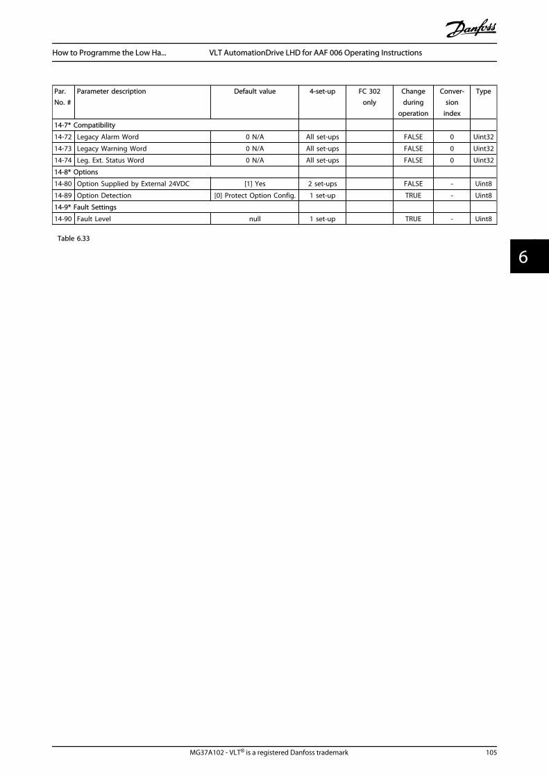
Par.No. #
Parameter description Default value 4-set-up FC 302only
Changeduring
operation
Conver-sion
index
Type
14-7* Compatibility
14-72 Legacy Alarm Word 0 N/A All set-ups FALSE 0 Uint32
14-73 Legacy Warning Word 0 N/A All set-ups FALSE 0 Uint32
14-74 Leg. Ext. Status Word 0 N/A All set-ups FALSE 0 Uint32
14-8* Options
14-80 Option Supplied by External 24VDC [1] Yes 2 set-ups FALSE - Uint8
14-89 Option Detection [0] Protect Option Config. 1 set-up TRUE - Uint8
14-9* Fault Settings
14-90 Fault Level null 1 set-up TRUE - Uint8
Table 6.33
How to Programme the Low Ha... VLT AutomationDrive LHD for AAF 006 Operating Instructions
MG37A102 - VLT® is a registered Danfoss trademark 105
6 6

6.3.15 15-** Drive Information
Par.No. #
Parameter description Default value 4-set-up FC 302only
Changeduring
operation
Conver-sion
index
Type
15-0* Operating Data
15-00 Operating Hours 0 h All set-ups FALSE 74 Uint32
15-01 Running Hours 0 h All set-ups FALSE 74 Uint32
15-02 kWh Counter 0 kWh All set-ups FALSE 75 Uint32
15-03 Power Up's 0 N/A All set-ups FALSE 0 Uint32
15-04 Over Temp's 0 N/A All set-ups FALSE 0 Uint16
15-05 Over Volt's 0 N/A All set-ups FALSE 0 Uint16
15-06 Reset kWh Counter [0] Do not reset All set-ups TRUE - Uint8
15-07 Reset Running Hours Counter [0] Do not reset All set-ups TRUE - Uint8
15-1* Data Log Settings
15-10 Logging Source 0 2 set-ups TRUE - Uint16
15-11 Logging Interval App.Dependent 2 set-ups TRUE -3 TimD
15-12 Trigger Event [0] False 1 set-up TRUE - Uint8
15-13 Logging Mode [0] Log always 2 set-ups TRUE - Uint8
15-14 Samples Before Trigger 50 N/A 2 set-ups TRUE 0 Uint8
15-2* Historic Log
15-20 Historic Log: Event 0 N/A All set-ups FALSE 0 Uint8
15-21 Historic Log: Value 0 N/A All set-ups FALSE 0 Uint32
15-22 Historic Log: Time 0 ms All set-ups FALSE -3 Uint32
15-3* Fault Log
15-30 Fault Log: Error Code 0 N/A All set-ups FALSE 0 Uint8
15-31 Fault Log: Value 0 N/A All set-ups FALSE 0 Int16
15-32 Fault Log: Time 0 s All set-ups FALSE 0 Uint32
15-4* Drive Identification
15-40 FC Type 0 N/A All set-ups FALSE 0 VisStr[6]
15-41 Power Section 0 N/A All set-ups FALSE 0 VisStr[20]
15-42 Voltage 0 N/A All set-ups FALSE 0 VisStr[20]
15-43 Software Version 0 N/A All set-ups FALSE 0 VisStr[5]
15-44 Ordered Typecode String 0 N/A All set-ups FALSE 0 VisStr[40]
15-45 Actual Typecode String 0 N/A All set-ups FALSE 0 VisStr[40]
15-46Frequency Converter OrderingNo 0 N/A All set-ups FALSE 0 VisStr[8]
15-47 Power Card Ordering No 0 N/A All set-ups FALSE 0 VisStr[8]
15-48 LCP Id No 0 N/A All set-ups FALSE 0 VisStr[20]
15-49 SW ID Control Card 0 N/A All set-ups FALSE 0 VisStr[20]
15-50 SW ID Power Card 0 N/A All set-ups FALSE 0 VisStr[20]
15-51Frequency Converter SerialNumber 0 N/A All set-ups FALSE 0 VisStr[10]
15-53 Power Card Serial Number 0 N/A All set-ups FALSE 0 VisStr[19]
15-59 CSIV Filename App.Dependent 1 set-up FALSE 0 VisStr[16]
Table 6.34
How to Programme the Low Ha... VLT AutomationDrive LHD for AAF 006 Operating Instructions
106 MG37A102 - VLT® is a registered Danfoss trademark
66

Par.No. #
Parameter description Default value 4-set-up FC 302only
Changeduring
operation
Conver-sion index
Type
15-6* Option Ident
15-60 Option Mounted 0 N/A All set-ups FALSE 0 VisStr[30]
15-61 Option SW Version 0 N/A All set-ups FALSE 0 VisStr[20]
15-62 Option Ordering No 0 N/A All set-ups FALSE 0 VisStr[8]
15-63 Option Serial No 0 N/A All set-ups FALSE 0 VisStr[18]
15-70 Option in Slot A 0 N/A All set-ups FALSE 0 VisStr[30]
15-71 Slot A Option SW Version 0 N/A All set-ups FALSE 0 VisStr[20]
15-72 Option in Slot B 0 N/A All set-ups FALSE 0 VisStr[30]
15-73 Slot B Option SW Version 0 N/A All set-ups FALSE 0 VisStr[20]
15-74 Option in Slot C0 0 N/A All set-ups FALSE 0 VisStr[30]
15-75 Slot C0 Option SW Version 0 N/A All set-ups FALSE 0 VisStr[20]
15-76 Option in Slot C1 0 N/A All set-ups FALSE 0 VisStr[30]
15-77 Slot C1 Option SW Version 0 N/A All set-ups FALSE 0 VisStr[20]
15-9* Parameter Info
15-92 Defined Parameters 0 N/A All set-ups FALSE 0 Uint16
15-93 Modified Parameters 0 N/A All set-ups FALSE 0 Uint16
15-98 Drive Identification 0 N/A All set-ups FALSE 0 VisStr[40]
15-99 Parameter Metadata 0 N/A All set-ups FALSE 0 Uint16
Table 6.35
How to Programme the Low Ha... VLT AutomationDrive LHD for AAF 006 Operating Instructions
MG37A102 - VLT® is a registered Danfoss trademark 107
6 6
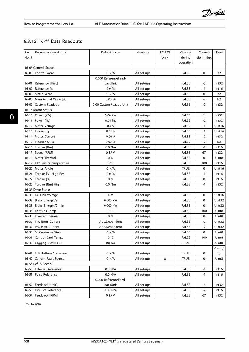
6.3.16 16-** Data Readouts
Par.No. #
Parameter description Default value 4-set-up FC 302only
Changeduring
operation
Conver-sion index
Type
16-0* General Status
16-00 Control Word 0 N/A All set-ups FALSE 0 V2
16-01 Reference [Unit]0.000 ReferenceFeed-
backUnit All set-ups FALSE -3 Int32
16-02 Reference % 0.0 % All set-ups FALSE -1 Int16
16-03 Status Word 0 N/A All set-ups FALSE 0 V2
16-05 Main Actual Value [%] 0.00 % All set-ups FALSE -2 N2
16-09 Custom Readout 0.00 CustomReadoutUnit All set-ups FALSE -2 Int32
16-1* Motor Status
16-10 Power [kW] 0.00 kW All set-ups FALSE 1 Int32
16-11 Power [hp] 0.00 hp All set-ups FALSE -2 Int32
16-12 Motor Voltage 0.0 V All set-ups FALSE -1 Uint16
16-13 Frequency 0.0 Hz All set-ups FALSE -1 Uint16
16-14 Motor Current 0.00 A All set-ups FALSE -2 Int32
16-15 Frequency [%] 0.00 % All set-ups FALSE -2 N2
16-16 Torque [Nm] 0.0 Nm All set-ups FALSE -1 Int16
16-17 Speed [RPM] 0 RPM All set-ups FALSE 67 Int32
16-18 Motor Thermal 0 % All set-ups FALSE 0 Uint8
16-19 KTY sensor temperature 0 °C All set-ups FALSE 100 Int16
16-20 Motor Angle 0 N/A All set-ups TRUE 0 Uint16
16-21 Torque [%] High Res. 0.0 % All set-ups FALSE -1 Int16
16-22 Torque [%] 0 % All set-ups FALSE 0 Int16
16-25 Torque [Nm] High 0.0 Nm All set-ups FALSE -1 Int32
16-3* Drive Status
16-30 DC Link Voltage 0 V All set-ups FALSE 0 Uint16
16-32 Brake Energy /s 0.000 kW All set-ups FALSE 0 Uint32
16-33 Brake Energy /2 min 0.000 kW All set-ups FALSE 0 Uint32
16-34 Heatsink Temp. 0 °C All set-ups FALSE 100 Uint8
16-35 Inverter Thermal 0 % All set-ups FALSE 0 Uint8
16-36 Inv. Nom. Current App.Dependent All set-ups FALSE -2 Uint32
16-37 Inv. Max. Current App.Dependent All set-ups FALSE -2 Uint32
16-38 SL Controller State 0 N/A All set-ups FALSE 0 Uint8
16-39 Control Card Temp. 0 °C All set-ups FALSE 100 Uint8
16-40 Logging Buffer Full [0] No All set-ups TRUE - Uint8
16-41 LCP Bottom Statusline 0 N/A All set-ups TRUE 0VisStr[5
0]
16-49 Current Fault Source 0 N/A All set-ups x TRUE 0 Uint8
16-5* Ref. & Feedb.
16-50 External Reference 0.0 N/A All set-ups FALSE -1 Int16
16-51 Pulse Reference 0.0 N/A All set-ups FALSE -1 Int16
16-52 Feedback [Unit]0.000 ReferenceFeed-
backUnit All set-ups FALSE -3 Int32
16-53 Digi Pot Reference 0.00 N/A All set-ups FALSE -2 Int16
16-57 Feedback [RPM] 0 RPM All set-ups FALSE 67 Int32
Table 6.36
How to Programme the Low Ha... VLT AutomationDrive LHD for AAF 006 Operating Instructions
108 MG37A102 - VLT® is a registered Danfoss trademark
66
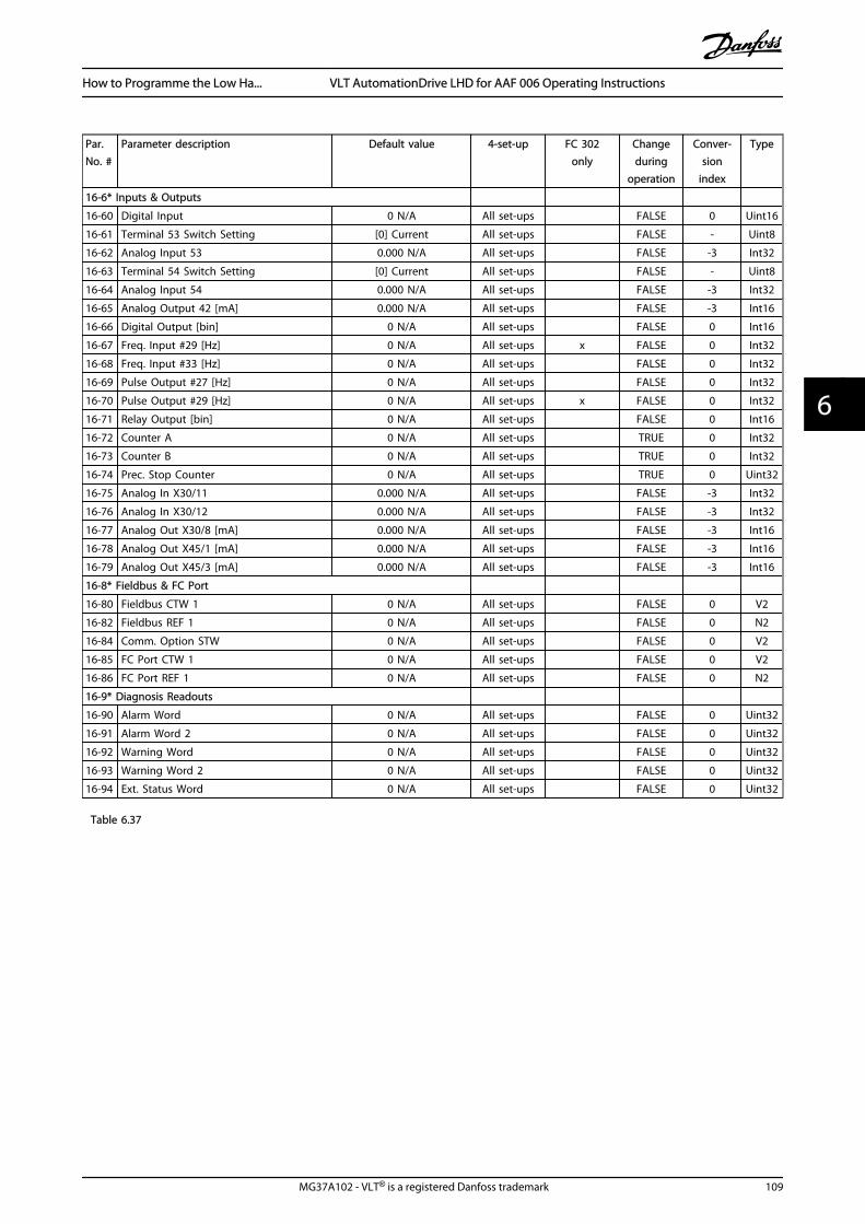
Par.No. #
Parameter description Default value 4-set-up FC 302only
Changeduring
operation
Conver-sion
index
Type
16-6* Inputs & Outputs
16-60 Digital Input 0 N/A All set-ups FALSE 0 Uint16
16-61 Terminal 53 Switch Setting [0] Current All set-ups FALSE - Uint8
16-62 Analog Input 53 0.000 N/A All set-ups FALSE -3 Int32
16-63 Terminal 54 Switch Setting [0] Current All set-ups FALSE - Uint8
16-64 Analog Input 54 0.000 N/A All set-ups FALSE -3 Int32
16-65 Analog Output 42 [mA] 0.000 N/A All set-ups FALSE -3 Int16
16-66 Digital Output [bin] 0 N/A All set-ups FALSE 0 Int16
16-67 Freq. Input #29 [Hz] 0 N/A All set-ups x FALSE 0 Int32
16-68 Freq. Input #33 [Hz] 0 N/A All set-ups FALSE 0 Int32
16-69 Pulse Output #27 [Hz] 0 N/A All set-ups FALSE 0 Int32
16-70 Pulse Output #29 [Hz] 0 N/A All set-ups x FALSE 0 Int32
16-71 Relay Output [bin] 0 N/A All set-ups FALSE 0 Int16
16-72 Counter A 0 N/A All set-ups TRUE 0 Int32
16-73 Counter B 0 N/A All set-ups TRUE 0 Int32
16-74 Prec. Stop Counter 0 N/A All set-ups TRUE 0 Uint32
16-75 Analog In X30/11 0.000 N/A All set-ups FALSE -3 Int32
16-76 Analog In X30/12 0.000 N/A All set-ups FALSE -3 Int32
16-77 Analog Out X30/8 [mA] 0.000 N/A All set-ups FALSE -3 Int16
16-78 Analog Out X45/1 [mA] 0.000 N/A All set-ups FALSE -3 Int16
16-79 Analog Out X45/3 [mA] 0.000 N/A All set-ups FALSE -3 Int16
16-8* Fieldbus & FC Port
16-80 Fieldbus CTW 1 0 N/A All set-ups FALSE 0 V2
16-82 Fieldbus REF 1 0 N/A All set-ups FALSE 0 N2
16-84 Comm. Option STW 0 N/A All set-ups FALSE 0 V2
16-85 FC Port CTW 1 0 N/A All set-ups FALSE 0 V2
16-86 FC Port REF 1 0 N/A All set-ups FALSE 0 N2
16-9* Diagnosis Readouts
16-90 Alarm Word 0 N/A All set-ups FALSE 0 Uint32
16-91 Alarm Word 2 0 N/A All set-ups FALSE 0 Uint32
16-92 Warning Word 0 N/A All set-ups FALSE 0 Uint32
16-93 Warning Word 2 0 N/A All set-ups FALSE 0 Uint32
16-94 Ext. Status Word 0 N/A All set-ups FALSE 0 Uint32
Table 6.37
How to Programme the Low Ha... VLT AutomationDrive LHD for AAF 006 Operating Instructions
MG37A102 - VLT® is a registered Danfoss trademark 109
6 6
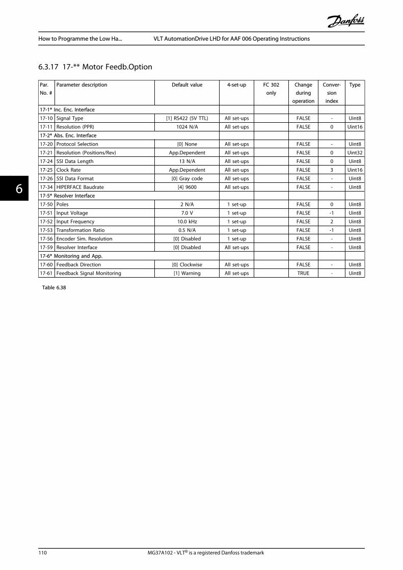
6.3.17 17-** Motor Feedb.Option
Par.No. #
Parameter description Default value 4-set-up FC 302only
Changeduring
operation
Conver-sion
index
Type
17-1* Inc. Enc. Interface
17-10 Signal Type [1] RS422 (5V TTL) All set-ups FALSE - Uint8
17-11 Resolution (PPR) 1024 N/A All set-ups FALSE 0 Uint16
17-2* Abs. Enc. Interface
17-20 Protocol Selection [0] None All set-ups FALSE - Uint8
17-21 Resolution (Positions/Rev) App.Dependent All set-ups FALSE 0 Uint32
17-24 SSI Data Length 13 N/A All set-ups FALSE 0 Uint8
17-25 Clock Rate App.Dependent All set-ups FALSE 3 Uint16
17-26 SSI Data Format [0] Gray code All set-ups FALSE - Uint8
17-34 HIPERFACE Baudrate [4] 9600 All set-ups FALSE - Uint8
17-5* Resolver Interface
17-50 Poles 2 N/A 1 set-up FALSE 0 Uint8
17-51 Input Voltage 7.0 V 1 set-up FALSE -1 Uint8
17-52 Input Frequency 10.0 kHz 1 set-up FALSE 2 Uint8
17-53 Transformation Ratio 0.5 N/A 1 set-up FALSE -1 Uint8
17-56 Encoder Sim. Resolution [0] Disabled 1 set-up FALSE - Uint8
17-59 Resolver Interface [0] Disabled All set-ups FALSE - Uint8
17-6* Monitoring and App.
17-60 Feedback Direction [0] Clockwise All set-ups FALSE - Uint8
17-61 Feedback Signal Monitoring [1] Warning All set-ups TRUE - Uint8
Table 6.38
How to Programme the Low Ha... VLT AutomationDrive LHD for AAF 006 Operating Instructions
110 MG37A102 - VLT® is a registered Danfoss trademark
66
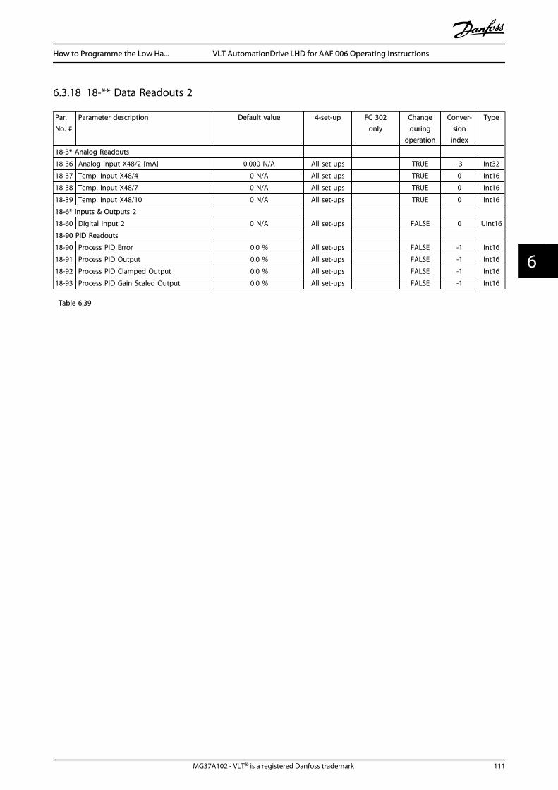
6.3.18 18-** Data Readouts 2
Par.No. #
Parameter description Default value 4-set-up FC 302only
Changeduring
operation
Conver-sion
index
Type
18-3* Analog Readouts
18-36 Analog Input X48/2 [mA] 0.000 N/A All set-ups TRUE -3 Int32
18-37 Temp. Input X48/4 0 N/A All set-ups TRUE 0 Int16
18-38 Temp. Input X48/7 0 N/A All set-ups TRUE 0 Int16
18-39 Temp. Input X48/10 0 N/A All set-ups TRUE 0 Int16
18-6* Inputs & Outputs 2
18-60 Digital Input 2 0 N/A All set-ups FALSE 0 Uint16
18-90 PID Readouts
18-90 Process PID Error 0.0 % All set-ups FALSE -1 Int16
18-91 Process PID Output 0.0 % All set-ups FALSE -1 Int16
18-92 Process PID Clamped Output 0.0 % All set-ups FALSE -1 Int16
18-93 Process PID Gain Scaled Output 0.0 % All set-ups FALSE -1 Int16
Table 6.39
How to Programme the Low Ha... VLT AutomationDrive LHD for AAF 006 Operating Instructions
MG37A102 - VLT® is a registered Danfoss trademark 111
6 6
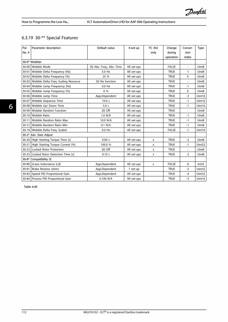
6.3.19 30-** Special Features
Par.No. #
Parameter description Default value 4-set-up FC 302only
Changeduring
operation
Conver-sion
index
Type
30-0* Wobbler
30-00 Wobble Mode [0] Abs. Freq., Abs. Time All set-ups FALSE - Uint8
30-01 Wobble Delta Frequency [Hz] 5.0 Hz All set-ups TRUE -1 Uint8
30-02 Wobble Delta Frequency [%] 25 % All set-ups TRUE 0 Uint8
30-03 Wobble Delta Freq. Scaling Resource [0] No function All set-ups TRUE - Uint8
30-04 Wobble Jump Frequency [Hz] 0.0 Hz All set-ups TRUE -1 Uint8
30-05 Wobble Jump Frequency [%] 0 % All set-ups TRUE 0 Uint8
30-06 Wobble Jump Time App.Dependent All set-ups TRUE -3 Uint16
30-07 Wobble Sequence Time 10.0 s All set-ups TRUE -1 Uint16
30-08 Wobble Up/ Down Time 5.0 s All set-ups TRUE -1 Uint16
30-09 Wobble Random Function [0] Off All set-ups TRUE - Uint8
30-10 Wobble Ratio 1.0 N/A All set-ups TRUE -1 Uint8
30-11 Wobble Random Ratio Max. 10.0 N/A All set-ups TRUE -1 Uint8
30-12 Wobble Random Ratio Min. 0.1 N/A All set-ups TRUE -1 Uint8
30-19 Wobble Delta Freq. Scaled 0.0 Hz All set-ups FALSE -1 Uint16
30-2* Adv. Start Adjust
30-20 High Starting Torque Time [s] 0.00 s All set-ups x TRUE -2 Uint8
30-21 High Starting Torque Current [%] 100.0 % All set-ups x TRUE -1 Uint32
30-22 Locked Rotor Protection [0] Off All set-ups x TRUE - Uint8
30-23 Locked Rotor Detection Time [s] 0.10 s All set-ups x TRUE -2 Uint8
30-8* Compatibility (I)
30-80 d-axis Inductance (Ld) App.Dependent All set-ups x FALSE -6 Int32
30-81 Brake Resistor (ohm) App.Dependent 1 set-up TRUE -2 Uint32
30-83 Speed PID Proportional Gain App.Dependent All set-ups TRUE -4 Uint32
30-84 Process PID Proportional Gain 0.100 N/A All set-ups TRUE -3 Uint16
Table 6.40
How to Programme the Low Ha... VLT AutomationDrive LHD for AAF 006 Operating Instructions
112 MG37A102 - VLT® is a registered Danfoss trademark
66

6.3.20 32-** MCO Basic Settings
Par.No. #
Parameter description Default value 4-set-up FC 302only
Changeduring
operation
Conver-sion
index
Type
32-0* Encoder 2
32-00 Incremental Signal Type [1] RS422 (5V TTL) 2 set-ups TRUE - Uint8
32-01 Incremental Resolution 1024 N/A 2 set-ups TRUE 0 Uint32
32-02 Absolute Protocol [0] None 2 set-ups TRUE - Uint8
32-03 Absolute Resolution 8192 N/A 2 set-ups TRUE 0 Uint32
32-04 Absolute Encoder Baudrate X55 [4] 9600 All set-ups FALSE - Uint8
32-05 Absolute Encoder Data Length 25 N/A 2 set-ups TRUE 0 Uint8
32-06 Absolute Encoder Clock Frequency 262.000 kHz 2 set-ups TRUE 0 Uint32
32-07 Absolute Encoder Clock Generation [1] On 2 set-ups TRUE - Uint8
32-08 Absolute Encoder Cable Length 0 m 2 set-ups TRUE 0 Uint16
32-09 Encoder Monitoring [0] Off 2 set-ups TRUE - Uint8
32-10 Rotational Direction [1] No action 2 set-ups TRUE - Uint8
32-11 User Unit Denominator 1 N/A 2 set-ups TRUE 0 Uint32
32-12 User Unit Numerator 1 N/A 2 set-ups TRUE 0 Uint32
32-13 Enc.2 Control [0] No soft changing 2 set-ups TRUE - Uint8
32-14 Enc.2 node ID 127 N/A 2 set-ups TRUE 0 Uint8
32-15 Enc.2 CAN guard null 2 set-ups TRUE - Uint8
32-3* Encoder 1
32-30 Incremental Signal Type [1] RS422 (5V TTL) 2 set-ups TRUE - Uint8
32-31 Incremental Resolution 1024 N/A 2 set-ups TRUE 0 Uint32
32-32 Absolute Protocol [0] None 2 set-ups TRUE - Uint8
32-33 Absolute Resolution 8192 N/A 2 set-ups TRUE 0 Uint32
32-35 Absolute Encoder Data Length 25 N/A 2 set-ups TRUE 0 Uint8
32-36 Absolute Encoder Clock Frequency 262.000 kHz 2 set-ups TRUE 0 Uint32
32-37 Absolute Encoder Clock Generation [1] On 2 set-ups TRUE - Uint8
32-38 Absolute Encoder Cable Length 0 m 2 set-ups TRUE 0 Uint16
32-39 Encoder Monitoring [0] Off 2 set-ups TRUE - Uint8
32-40 Encoder Termination [1] On 2 set-ups TRUE - Uint8
32-43 Enc.1 Control [0] No soft changing 2 set-ups TRUE - Uint8
32-44 Enc.1 node ID 127 N/A 2 set-ups TRUE 0 Uint8
32-45 Enc.1 CAN guard null 2 set-ups TRUE - Uint8
32-5* Feedback Source
32-50 Source Slave [2] Encoder 2 2 set-ups TRUE - Uint8
32-51 MCO 302 Last Will [1] Trip 2 set-ups TRUE - Uint8
32-52 Source Master [1] Encoder 1 X56 2 set-ups TRUE - Uint8
Table 6.41
How to Programme the Low Ha... VLT AutomationDrive LHD for AAF 006 Operating Instructions
MG37A102 - VLT® is a registered Danfoss trademark 113
6 6
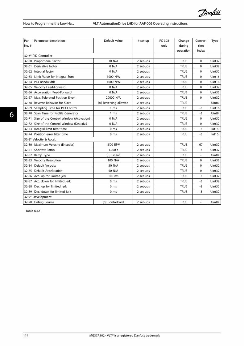
Par.No. #
Parameter description Default value 4-set-up FC 302only
Changeduring
operation
Conver-sion
index
Type
32-6* PID Controller
32-60 Proportional factor 30 N/A 2 set-ups TRUE 0 Uint32
32-61 Derivative factor 0 N/A 2 set-ups TRUE 0 Uint32
32-62 Integral factor 0 N/A 2 set-ups TRUE 0 Uint32
32-63 Limit Value for Integral Sum 1000 N/A 2 set-ups TRUE 0 Uint16
32-64 PID Bandwidth 1000 N/A 2 set-ups TRUE 0 Uint16
32-65 Velocity Feed-Forward 0 N/A 2 set-ups TRUE 0 Uint32
32-66 Acceleration Feed-Forward 0 N/A 2 set-ups TRUE 0 Uint32
32-67 Max. Tolerated Position Error 20000 N/A 2 set-ups TRUE 0 Uint32
32-68 Reverse Behavior for Slave [0] Reversing allowed 2 set-ups TRUE - Uint8
32-69 Sampling Time for PID Control 1 ms 2 set-ups TRUE -3 Uint16
32-70 Scan Time for Profile Generator 1 ms 2 set-ups TRUE -3 Uint8
32-71 Size of the Control Window (Activation) 0 N/A 2 set-ups TRUE 0 Uint32
32-72 Size of the Control Window (Deactiv.) 0 N/A 2 set-ups TRUE 0 Uint32
32-73 Integral limit filter time 0 ms 2 set-ups TRUE -3 Int16
32-74 Position error filter time 0 ms 2 set-ups TRUE -3 Int16
32-8* Velocity & Accel.
32-80 Maximum Velocity (Encoder) 1500 RPM 2 set-ups TRUE 67 Uint32
32-81 Shortest Ramp 1.000 s 2 set-ups TRUE -3 Uint32
32-82 Ramp Type [0] Linear 2 set-ups TRUE - Uint8
32-83 Velocity Resolution 100 N/A 2 set-ups TRUE 0 Uint32
32-84 Default Velocity 50 N/A 2 set-ups TRUE 0 Uint32
32-85 Default Acceleration 50 N/A 2 set-ups TRUE 0 Uint32
32-86 Acc. up for limited jerk 100 ms 2 set-ups TRUE -3 Uint32
32-87 Acc. down for limited jerk 0 ms 2 set-ups TRUE -3 Uint32
32-88 Dec. up for limited jerk 0 ms 2 set-ups TRUE -3 Uint32
32-89 Dec. down for limited jerk 0 ms 2 set-ups TRUE -3 Uint32
32-9* Development
32-90 Debug Source [0] Controlcard 2 set-ups TRUE - Uint8
Table 6.42
How to Programme the Low Ha... VLT AutomationDrive LHD for AAF 006 Operating Instructions
114 MG37A102 - VLT® is a registered Danfoss trademark
66
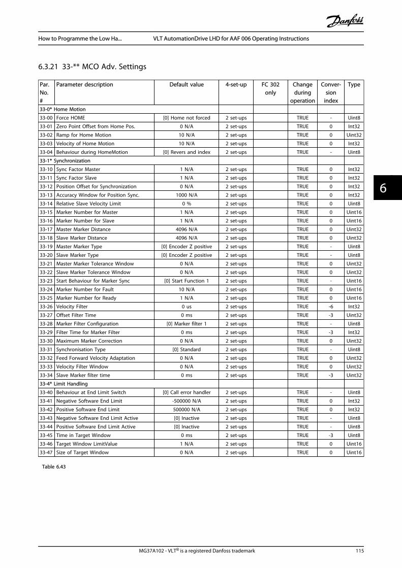
6.3.21 33-** MCO Adv. Settings
Par.No.#
Parameter description Default value 4-set-up FC 302only
Changeduring
operation
Conver-sion
index
Type
33-0* Home Motion
33-00 Force HOME [0] Home not forced 2 set-ups TRUE - Uint8
33-01 Zero Point Offset from Home Pos. 0 N/A 2 set-ups TRUE 0 Int32
33-02 Ramp for Home Motion 10 N/A 2 set-ups TRUE 0 Uint32
33-03 Velocity of Home Motion 10 N/A 2 set-ups TRUE 0 Int32
33-04 Behaviour during HomeMotion [0] Revers and index 2 set-ups TRUE - Uint8
33-1* Synchronization
33-10 Sync Factor Master 1 N/A 2 set-ups TRUE 0 Int32
33-11 Sync Factor Slave 1 N/A 2 set-ups TRUE 0 Int32
33-12 Position Offset for Synchronization 0 N/A 2 set-ups TRUE 0 Int32
33-13 Accuracy Window for Position Sync. 1000 N/A 2 set-ups TRUE 0 Int32
33-14 Relative Slave Velocity Limit 0 % 2 set-ups TRUE 0 Uint8
33-15 Marker Number for Master 1 N/A 2 set-ups TRUE 0 Uint16
33-16 Marker Number for Slave 1 N/A 2 set-ups TRUE 0 Uint16
33-17 Master Marker Distance 4096 N/A 2 set-ups TRUE 0 Uint32
33-18 Slave Marker Distance 4096 N/A 2 set-ups TRUE 0 Uint32
33-19 Master Marker Type [0] Encoder Z positive 2 set-ups TRUE - Uint8
33-20 Slave Marker Type [0] Encoder Z positive 2 set-ups TRUE - Uint8
33-21 Master Marker Tolerance Window 0 N/A 2 set-ups TRUE 0 Uint32
33-22 Slave Marker Tolerance Window 0 N/A 2 set-ups TRUE 0 Uint32
33-23 Start Behaviour for Marker Sync [0] Start Function 1 2 set-ups TRUE - Uint16
33-24 Marker Number for Fault 10 N/A 2 set-ups TRUE 0 Uint16
33-25 Marker Number for Ready 1 N/A 2 set-ups TRUE 0 Uint16
33-26 Velocity Filter 0 us 2 set-ups TRUE -6 Int32
33-27 Offset Filter Time 0 ms 2 set-ups TRUE -3 Uint32
33-28 Marker Filter Configuration [0] Marker filter 1 2 set-ups TRUE - Uint8
33-29 Filter Time for Marker Filter 0 ms 2 set-ups TRUE -3 Int32
33-30 Maximum Marker Correction 0 N/A 2 set-ups TRUE 0 Uint32
33-31 Synchronisation Type [0] Standard 2 set-ups TRUE - Uint8
33-32 Feed Forward Velocity Adaptation 0 N/A 2 set-ups TRUE 0 Uint32
33-33 Velocity Filter Window 0 N/A 2 set-ups TRUE 0 Uint32
33-34 Slave Marker filter time 0 ms 2 set-ups TRUE -3 Uint32
33-4* Limit Handling
33-40 Behaviour at End Limit Switch [0] Call error handler 2 set-ups TRUE - Uint8
33-41 Negative Software End Limit -500000 N/A 2 set-ups TRUE 0 Int32
33-42 Positive Software End Limit 500000 N/A 2 set-ups TRUE 0 Int32
33-43 Negative Software End Limit Active [0] Inactive 2 set-ups TRUE - Uint8
33-44 Positive Software End Limit Active [0] Inactive 2 set-ups TRUE - Uint8
33-45 Time in Target Window 0 ms 2 set-ups TRUE -3 Uint8
33-46 Target Window LimitValue 1 N/A 2 set-ups TRUE 0 Uint16
33-47 Size of Target Window 0 N/A 2 set-ups TRUE 0 Uint16
Table 6.43
How to Programme the Low Ha... VLT AutomationDrive LHD for AAF 006 Operating Instructions
MG37A102 - VLT® is a registered Danfoss trademark 115
6 6

Par.No. #
Parameter description Default value 4-set-up FC 302only
Changeduring
operation
Conver-sion
index
Type
33-5* I/O Configuration
33-50 Terminal X57/1 Digital Input [0] No function 2 set-ups TRUE - Uint8
33-51 Terminal X57/2 Digital Input [0] No function 2 set-ups TRUE - Uint8
33-52 Terminal X57/3 Digital Input [0] No function 2 set-ups TRUE - Uint8
33-53 Terminal X57/4 Digital Input [0] No function 2 set-ups TRUE - Uint8
33-54 Terminal X57/5 Digital Input [0] No function 2 set-ups TRUE - Uint8
33-55 Terminal X57/6 Digital Input [0] No function 2 set-ups TRUE - Uint8
33-56 Terminal X57/7 Digital Input [0] No function 2 set-ups TRUE - Uint8
33-57 Terminal X57/8 Digital Input [0] No function 2 set-ups TRUE - Uint8
33-58 Terminal X57/9 Digital Input [0] No function 2 set-ups TRUE - Uint8
33-59 Terminal X57/10 Digital Input [0] No function 2 set-ups TRUE - Uint8
33-60 Terminal X59/1 and X59/2 Mode [1] Output 2 set-ups FALSE - Uint8
33-61 Terminal X59/1 Digital Input [0] No function 2 set-ups TRUE - Uint8
33-62 Terminal X59/2 Digital Input [0] No function 2 set-ups TRUE - Uint8
33-63 Terminal X59/1 Digital Output [0] No function 2 set-ups TRUE - Uint8
33-64 Terminal X59/2 Digital Output [0] No function 2 set-ups TRUE - Uint8
33-65 Terminal X59/3 Digital Output [0] No function 2 set-ups TRUE - Uint8
33-66 Terminal X59/4 Digital Output [0] No function 2 set-ups TRUE - Uint8
33-67 Terminal X59/5 Digital Output [0] No function 2 set-ups TRUE - Uint8
33-68 Terminal X59/6 Digital Output [0] No function 2 set-ups TRUE - Uint8
33-69 Terminal X59/7 Digital Output [0] No function 2 set-ups TRUE - Uint8
33-70 Terminal X59/8 Digital Output [0] No function 2 set-ups TRUE - Uint8
33-8* Global Parameters
33-80 Activated Program Number -1 N/A 2 set-ups TRUE 0 Int8
33-81 Power-up State [1] Motor on 2 set-ups TRUE - Uint8
33-82 Drive Status Monitoring [1] On 2 set-ups TRUE - Uint8
33-83 Behaviour afterError [0] Coast 2 set-ups TRUE - Uint8
33-84 Behaviour afterEsc. [0] Controlled stop 2 set-ups TRUE - Uint8
33-85 MCO Supplied by External 24VDC [0] No 2 set-ups TRUE - Uint8
33-86 Terminal at alarm [0] Relay 1 2 set-ups TRUE - Uint8
33-87 Terminal state at alarm [0] Do nothing 2 set-ups TRUE - Uint8
33-88 Status word at alarm 0 N/A 2 set-ups TRUE 0 Uint16
33-9* MCO Port Settings
33-90 X62 MCO CAN node ID 127 N/A 2 set-ups TRUE 0 Uint8
33-91 X62 MCO CAN baud rate [20] 125 Kbps 2 set-ups TRUE - Uint8
33-94 X60 MCO RS485 serial termination [0] Off 2 set-ups TRUE - Uint8
33-95 X60 MCO RS485 serial baud rate [2] 9600 Baud 2 set-ups TRUE - Uint8
Table 6.44
How to Programme the Low Ha... VLT AutomationDrive LHD for AAF 006 Operating Instructions
116 MG37A102 - VLT® is a registered Danfoss trademark
66

6.3.22 34-** MCO Data Readouts
Par.No. #
Parameter description Default value 4-set-up FC 302only
Changeduring
operation
Conver-sion
index
Type
34-0* PCD Write Par.
34-01 PCD 1 Write to MCO 0 N/A All set-ups TRUE 0 Uint16
34-02 PCD 2 Write to MCO 0 N/A All set-ups TRUE 0 Uint16
34-03 PCD 3 Write to MCO 0 N/A All set-ups TRUE 0 Uint16
34-04 PCD 4 Write to MCO 0 N/A All set-ups TRUE 0 Uint16
34-05 PCD 5 Write to MCO 0 N/A All set-ups TRUE 0 Uint16
34-06 PCD 6 Write to MCO 0 N/A All set-ups TRUE 0 Uint16
34-07 PCD 7 Write to MCO 0 N/A All set-ups TRUE 0 Uint16
34-08 PCD 8 Write to MCO 0 N/A All set-ups TRUE 0 Uint16
34-09 PCD 9 Write to MCO 0 N/A All set-ups TRUE 0 Uint16
34-10 PCD 10 Write to MCO 0 N/A All set-ups TRUE 0 Uint16
34-2* PCD Read Par.
34-21 PCD 1 Read from MCO 0 N/A All set-ups TRUE 0 Uint16
34-22 PCD 2 Read from MCO 0 N/A All set-ups TRUE 0 Uint16
34-23 PCD 3 Read from MCO 0 N/A All set-ups TRUE 0 Uint16
34-24 PCD 4 Read from MCO 0 N/A All set-ups TRUE 0 Uint16
34-25 PCD 5 Read from MCO 0 N/A All set-ups TRUE 0 Uint16
34-26 PCD 6 Read from MCO 0 N/A All set-ups TRUE 0 Uint16
34-27 PCD 7 Read from MCO 0 N/A All set-ups TRUE 0 Uint16
34-28 PCD 8 Read from MCO 0 N/A All set-ups TRUE 0 Uint16
34-29 PCD 9 Read from MCO 0 N/A All set-ups TRUE 0 Uint16
34-30 PCD 10 Read from MCO 0 N/A All set-ups TRUE 0 Uint16
34-4* Inputs & Outputs
34-40 Digital Inputs 0 N/A All set-ups TRUE 0 Uint16
34-41 Digital Outputs 0 N/A All set-ups TRUE 0 Uint16
34-5* Process Data
34-50 Actual Position 0 N/A All set-ups TRUE 0 Int32
34-51 Commanded Position 0 N/A All set-ups TRUE 0 Int32
34-52 Actual Master Position 0 N/A All set-ups TRUE 0 Int32
34-53 Slave Index Position 0 N/A All set-ups TRUE 0 Int32
34-54 Master Index Position 0 N/A All set-ups TRUE 0 Int32
34-55 Curve Position 0 N/A All set-ups TRUE 0 Int32
34-56 Track Error 0 N/A All set-ups TRUE 0 Int32
34-57 Synchronizing Error 0 N/A All set-ups TRUE 0 Int32
34-58 Actual Velocity 0 N/A All set-ups TRUE 0 Int32
34-59 Actual Master Velocity 0 N/A All set-ups TRUE 0 Int32
34-60 Synchronizing Status 0 N/A All set-ups TRUE 0 Int32
34-61 Axis Status 0 N/A All set-ups TRUE 0 Int32
34-62 Program Status 0 N/A All set-ups TRUE 0 Int32
34-64 MCO 302 Status 0 N/A All set-ups TRUE 0 Uint16
34-65 MCO 302 Control 0 N/A All set-ups TRUE 0 Uint16
34-7* Diagnosis readouts
34-70 MCO Alarm Word 1 0 N/A All set-ups FALSE 0 Uint32
34-71 MCO Alarm Word 2 0 N/A All set-ups FALSE 0 Uint32
Table 6.45
How to Programme the Low Ha... VLT AutomationDrive LHD for AAF 006 Operating Instructions
MG37A102 - VLT® is a registered Danfoss trademark 117
6 6

6.3.23 35-** Sensor Input Option
Par.No. #
Parameter description Default value 4-set-up FC 302only
Changeduring
operation
Conver-sion
index
Type
35-0* Temp. Input Mode
35-00 Term. X48/4 Temp. Unit [60] °C All set-ups TRUE - Uint8
35-01 Term. X48/4 Input Type [0] Not Connected All set-ups TRUE - Uint8
35-02 Term. X48/7 Temp. Unit [60] °C All set-ups TRUE - Uint8
35-03 Term. X48/7 Input Type [0] Not Connected All set-ups TRUE - Uint8
35-04 Term. X48/10 Temp. Unit [60] °C All set-ups TRUE - Uint8
35-05 Term. X48/10 Input Type [0] Not Connected All set-ups TRUE - Uint8
35-06 Temperature Sensor Alarm Function [5] Stop and trip All set-ups TRUE - Uint8
35-1* Temp. Input X48/4
35-14 Term. X48/4 Filter Time Constant 0.001 s All set-ups TRUE -3 Uint16
35-15 Term. X48/4 Temp. Monitor [0] Disabled All set-ups TRUE - Uint8
35-16 Term. X48/4 Low Temp. Limit App.Dependent All set-ups TRUE 0 Int16
35-17 Term. X48/4 High Temp. Limit App.Dependent All set-ups TRUE 0 Int16
35-2* Temp. Input X48/7
35-24 Term. X48/7 Filter Time Constant 0.001 s All set-ups TRUE -3 Uint16
35-25 Term. X48/7 Temp. Monitor [0] Disabled All set-ups TRUE - Uint8
35-26 Term. X48/7 Low Temp. Limit App.Dependent All set-ups TRUE 0 Int16
35-27 Term. X48/7 High Temp. Limit App.Dependent All set-ups TRUE 0 Int16
35-3* Temp. Input X48/10
35-34 Term. X48/10 Filter Time Constant 0.001 s All set-ups TRUE -3 Uint16
35-35 Term. X48/10 Temp. Monitor [0] Disabled All set-ups TRUE - Uint8
35-36 Term. X48/10 Low Temp. Limit App.Dependent All set-ups TRUE 0 Int16
35-37 Term. X48/10 High Temp. Limit App.Dependent All set-ups TRUE 0 Int16
35-4* Analog Input X48/2
35-42 Term. X48/2 Low Current 4.00 mA All set-ups TRUE -5 Int16
35-43 Term. X48/2 High Current 20.00 mA All set-ups TRUE -5 Int16
35-44 Term. X48/2 Low Ref./Feedb. Value 0.000 N/A All set-ups TRUE -3 Int32
35-45 Term. X48/2 High Ref./Feedb. Value 100.000 N/A All set-ups TRUE -3 Int32
35-46 Term. X48/2 Filter Time Constant 0.001 s All set-ups TRUE -3 Uint16
Table 6.46
How to Programme the Low Ha... VLT AutomationDrive LHD for AAF 006 Operating Instructions
118 MG37A102 - VLT® is a registered Danfoss trademark
66

6.4 Parameter Lists - Active Filter
6.4.1 Operation/Display 0-**
Par.No. #
Parameter description Default value 4-set-up FC 302only
Changeduring
operation
Conver-sion
index
Type
0-0* Basic Settings
0-01 Language [0] English 1 set-up TRUE - Uint8
0-04 Operating State at Power-up (Hand) [1] Forced stop All set-ups TRUE - Uint8
0-1* Set-up Operations
0-10 Active Set-up [1] Set-up 1 1 set-up TRUE - Uint8
0-11 Edit Set-up [1] Set-up 1 All set-ups TRUE - Uint8
0-12 This Set-up Linked to [0] Not linked All set-ups FALSE - Uint8
0-13 Readout: Linked Set-ups 0 N/A All set-ups FALSE 0 Uint16
0-14 Readout: Edit Set-ups / Channel 0 N/A All set-ups TRUE 0 Int32
0-2* LCP Display
0-20 Display Line 1.1 Small 30112 All set-ups TRUE - Uint16
0-21 Display Line 1.2 Small 30110 All set-ups TRUE - Uint16
0-22 Display Line 1.3 Small 30120 All set-ups TRUE - Uint16
0-23 Display Line 2 Large 30100 All set-ups TRUE - Uint16
0-24 Display Line 3 Large 30121 All set-ups TRUE - Uint16
0-25 My Personal Menu ExpressionLimit 1 set-up TRUE 0 Uint16
0-4* LCP Keypad
0-40 [Hand on] Key on LCP [1] Enabled All set-ups TRUE - Uint8
0-41 [Off] Key on LCP [1] Enabled All set-ups TRUE - Uint8
0-42 [Auto on] Key on LCP [1] Enabled All set-ups TRUE - Uint8
0-43 [Reset] Key on LCP [1] Enabled All set-ups TRUE - Uint8
0-5* Copy/Save
0-50 LCP Copy [0] No copy All set-ups FALSE - Uint8
0-51 Set-up Copy [0] No copy All set-ups FALSE - Uint8
0-6* Password
0-60 Main Menu Password 100 N/A 1 set-up TRUE 0 Int16
0-61 Access to Main Menu w/o Password [0] Full access 1 set-up TRUE - Uint8
0-65 Quick Menu Password 200 N/A 1 set-up TRUE 0 Int16
0-66 Access to Quick Menu w/o Password [0] Full access 1 set-up TRUE - Uint8
Table 6.47
How to Programme the Low Ha... VLT AutomationDrive LHD for AAF 006 Operating Instructions
MG37A102 - VLT® is a registered Danfoss trademark 119
6 6
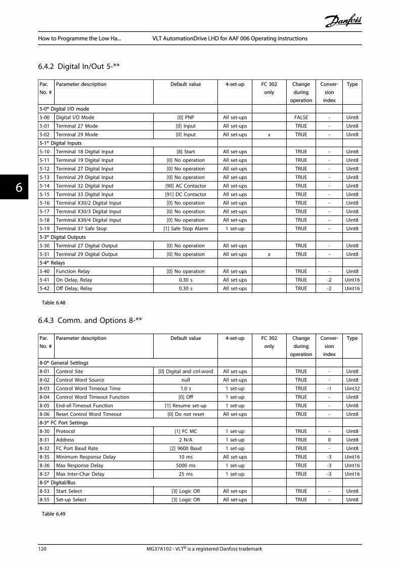
6.4.2 Digital In/Out 5-**
Par.No. #
Parameter description Default value 4-set-up FC 302only
Changeduring
operation
Conver-sion
index
Type
5-0* Digital I/O mode
5-00 Digital I/O Mode [0] PNP All set-ups FALSE - Uint8
5-01 Terminal 27 Mode [0] Input All set-ups TRUE - Uint8
5-02 Terminal 29 Mode [0] Input All set-ups x TRUE - Uint8
5-1* Digital Inputs
5-10 Terminal 18 Digital Input [8] Start All set-ups TRUE - Uint8
5-11 Terminal 19 Digital Input [0] No operation All set-ups TRUE - Uint8
5-12 Terminal 27 Digital Input [0] No operation All set-ups TRUE - Uint8
5-13 Terminal 29 Digital Input [0] No operation All set-ups TRUE - Uint8
5-14 Terminal 32 Digital Input [90] AC Contactor All set-ups TRUE - Uint8
5-15 Terminal 33 Digital Input [91] DC Contactor All set-ups TRUE - Uint8
5-16 Terminal X30/2 Digital Input [0] No operation All set-ups TRUE - Uint8
5-17 Terminal X30/3 Digital Input [0] No operation All set-ups TRUE - Uint8
5-18 Terminal X30/4 Digital Input [0] No operation All set-ups TRUE - Uint8
5-19 Terminal 37 Safe Stop [1] Safe Stop Alarm 1 set-up TRUE - Uint8
5-3* Digital Outputs
5-30 Terminal 27 Digital Output [0] No operation All set-ups TRUE - Uint8
5-31 Terminal 29 Digital Output [0] No operation All set-ups x TRUE - Uint8
5-4* Relays
5-40 Function Relay [0] No operation All set-ups TRUE - Uint8
5-41 On Delay, Relay 0.30 s All set-ups TRUE -2 Uint16
5-42 Off Delay, Relay 0.30 s All set-ups TRUE -2 Uint16
Table 6.48
6.4.3 Comm. and Options 8-**
Par.No. #
Parameter description Default value 4-set-up FC 302only
Changeduring
operation
Conver-sion
index
Type
8-0* General Settings
8-01 Control Site [0] Digital and ctrl.word All set-ups TRUE - Uint8
8-02 Control Word Source null All set-ups TRUE - Uint8
8-03 Control Word Timeout Time 1.0 s 1 set-up TRUE -1 Uint32
8-04 Control Word Timeout Function [0] Off 1 set-up TRUE - Uint8
8-05 End-of-Timeout Function [1] Resume set-up 1 set-up TRUE - Uint8
8-06 Reset Control Word Timeout [0] Do not reset All set-ups TRUE - Uint8
8-3* FC Port Settings
8-30 Protocol [1] FC MC 1 set-up TRUE - Uint8
8-31 Address 2 N/A 1 set-up TRUE 0 Uint8
8-32 FC Port Baud Rate [2] 9600 Baud 1 set-up TRUE - Uint8
8-35 Minimum Response Delay 10 ms All set-ups TRUE -3 Uint16
8-36 Max Response Delay 5000 ms 1 set-up TRUE -3 Uint16
8-37 Max Inter-Char Delay 25 ms 1 set-up TRUE -3 Uint16
8-5* Digital/Bus
8-53 Start Select [3] Logic OR All set-ups TRUE - Uint8
8-55 Set-up Select [3] Logic OR All set-ups TRUE - Uint8
Table 6.49
How to Programme the Low Ha... VLT AutomationDrive LHD for AAF 006 Operating Instructions
120 MG37A102 - VLT® is a registered Danfoss trademark
66

6.4.4 Special Functions 14-**
Par.No. #
Parameter description Default value 4-set-up FC 302only
Changeduring
operation
Conver-sion
index
Type
14-2* Trip Reset
14-20 Reset Mode [0] Manual reset All set-ups TRUE - Uint8
14-21 Automatic Restart Time 10 s All set-ups TRUE 0 Uint16
14-22 Operation Mode [0] Normal operation All set-ups TRUE - Uint8
14-23 Typecode Setting null 2 set-ups FALSE - Uint8
14-28 Production Settings [0] No action All set-ups TRUE - Uint8
14-29 Service Code 0 N/A All set-ups TRUE 0 Int32
14-5* Environment
14-50 RFI Filter [1] On 1 set-up FALSE - Uint8
14-53 Fan Monitor [1] Warning All set-ups TRUE - Uint8
14-54 Bus Partner 1 N/A 2 set-ups TRUE 0 Uint16
Table 6.50
How to Programme the Low Ha... VLT AutomationDrive LHD for AAF 006 Operating Instructions
MG37A102 - VLT® is a registered Danfoss trademark 121
6 6

6.4.5 FC Information 15-**
Par.No. #
Parameter description Default value 4-set-up FC 302only
Changeduring
operation
Conver-sion index
Type
15-0* Operating Data
15-00 Operating Hours 0 h All set-ups FALSE 74 Uint32
15-01 Running Hours 0 h All set-ups FALSE 74 Uint32
15-03 Power Up's 0 N/A All set-ups FALSE 0 Uint32
15-04 Over Temp's 0 N/A All set-ups FALSE 0 Uint16
15-05 Over Volt's 0 N/A All set-ups FALSE 0 Uint16
15-07 Reset Running Hours Counter [0] Do not reset All set-ups TRUE - Uint8
15-1* Data Log Settings
15-10 Logging Source 0 2 set-ups TRUE - Uint16
15-11 Logging Interval ExpressionLimit 2 set-ups TRUE -3 TimD
15-12 Trigger Event [0] False 1 set-up TRUE - Uint8
15-13 Logging Mode [0] Log always 2 set-ups TRUE - Uint8
15-14 Samples Before Trigger 50 N/A 2 set-ups TRUE 0 Uint8
15-2* Historic Log
15-20 Historic Log: Event 0 N/A All set-ups FALSE 0 Uint8
15-21 Historic Log: Value 0 N/A All set-ups FALSE 0 Uint32
15-22 Historic Log: Time 0 ms All set-ups FALSE -3 Uint32
15-3* Fault Log
15-30 Fault Log: Error Code 0 N/A All set-ups FALSE 0 Uint16
15-31 Fault Log: Value 0 N/A All set-ups FALSE 0 Int16
15-32 Fault Log: Time 0 s All set-ups FALSE 0 Uint32
15-4* Unit Identification
15-40 FC Type 0 N/A All set-ups FALSE 0 VisStr[6]
15-41 Power Section 0 N/A All set-ups FALSE 0 VisStr[20]
15-42 Voltage 0 N/A All set-ups FALSE 0 VisStr[20]
15-43 Software Version 0 N/A All set-ups FALSE 0 VisStr[5]
15-44 Ordered Typecode String 0 N/A All set-ups FALSE 0 VisStr[40]
15-45 Actual Typecode String 0 N/A All set-ups FALSE 0 VisStr[40]
15-46 Unit Ordering No 0 N/A All set-ups FALSE 0 VisStr[8]
15-47 Power Card Ordering No 0 N/A All set-ups FALSE 0 VisStr[8]
15-48 LCP Id No 0 N/A All set-ups FALSE 0 VisStr[20]
15-49 SW ID Control Card 0 N/A All set-ups FALSE 0 VisStr[20]
15-50 SW ID Power Card 0 N/A All set-ups FALSE 0 VisStr[20]
15-51 Unit Serial Number 0 N/A All set-ups FALSE 0 VisStr[10]
15-53 Power Card Serial Number 0 N/A All set-ups FALSE 0 VisStr[19]
15-6* Option Ident
15-60 Option Mounted 0 N/A All set-ups FALSE 0 VisStr[30]
15-61 Option SW Version 0 N/A All set-ups FALSE 0 VisStr[20]
15-62 Option Ordering No 0 N/A All set-ups FALSE 0 VisStr[8]
15-63 Option Serial No 0 N/A All set-ups FALSE 0 VisStr[18]
15-70 Option in Slot A 0 N/A All set-ups FALSE 0 VisStr[30]
15-71 Slot A Option SW Version 0 N/A All set-ups FALSE 0 VisStr[20]
15-72 Option in Slot B 0 N/A All set-ups FALSE 0 VisStr[30]
15-73 Slot B Option SW Version 0 N/A All set-ups FALSE 0 VisStr[20]
15-74 Option in Slot C0 0 N/A All set-ups FALSE 0 VisStr[30]
15-75 Slot C0 Option SW Version 0 N/A All set-ups FALSE 0 VisStr[20]
15-76 Option in Slot C1 0 N/A All set-ups FALSE 0 VisStr[30]
15-77 Slot C1 Option SW Version 0 N/A All set-ups FALSE 0 VisStr[20]
Table 6.51
How to Programme the Low Ha... VLT AutomationDrive LHD for AAF 006 Operating Instructions
122 MG37A102 - VLT® is a registered Danfoss trademark
66
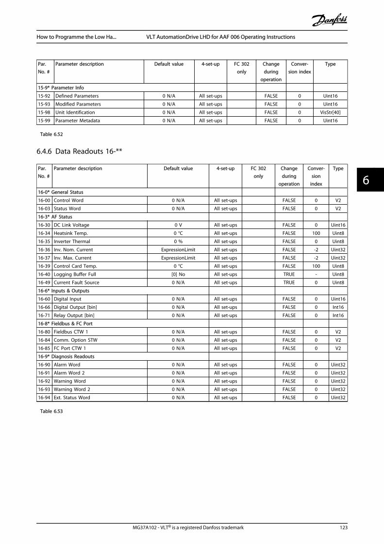
Par.No. #
Parameter description Default value 4-set-up FC 302only
Changeduring
operation
Conver-sion index
Type
15-9* Parameter Info
15-92 Defined Parameters 0 N/A All set-ups FALSE 0 Uint16
15-93 Modified Parameters 0 N/A All set-ups FALSE 0 Uint16
15-98 Unit Identification 0 N/A All set-ups FALSE 0 VisStr[40]
15-99 Parameter Metadata 0 N/A All set-ups FALSE 0 Uint16
Table 6.52
6.4.6 Data Readouts 16-**
Par.No. #
Parameter description Default value 4-set-up FC 302only
Changeduring
operation
Conver-sion
index
Type
16-0* General Status
16-00 Control Word 0 N/A All set-ups FALSE 0 V2
16-03 Status Word 0 N/A All set-ups FALSE 0 V2
16-3* AF Status
16-30 DC Link Voltage 0 V All set-ups FALSE 0 Uint16
16-34 Heatsink Temp. 0 °C All set-ups FALSE 100 Uint8
16-35 Inverter Thermal 0 % All set-ups FALSE 0 Uint8
16-36 Inv. Nom. Current ExpressionLimit All set-ups FALSE -2 Uint32
16-37 Inv. Max. Current ExpressionLimit All set-ups FALSE -2 Uint32
16-39 Control Card Temp. 0 °C All set-ups FALSE 100 Uint8
16-40 Logging Buffer Full [0] No All set-ups TRUE - Uint8
16-49 Current Fault Source 0 N/A All set-ups TRUE 0 Uint8
16-6* Inputs & Outputs
16-60 Digital Input 0 N/A All set-ups FALSE 0 Uint16
16-66 Digital Output [bin] 0 N/A All set-ups FALSE 0 Int16
16-71 Relay Output [bin] 0 N/A All set-ups FALSE 0 Int16
16-8* Fieldbus & FC Port
16-80 Fieldbus CTW 1 0 N/A All set-ups FALSE 0 V2
16-84 Comm. Option STW 0 N/A All set-ups FALSE 0 V2
16-85 FC Port CTW 1 0 N/A All set-ups FALSE 0 V2
16-9* Diagnosis Readouts
16-90 Alarm Word 0 N/A All set-ups FALSE 0 Uint32
16-91 Alarm Word 2 0 N/A All set-ups FALSE 0 Uint32
16-92 Warning Word 0 N/A All set-ups FALSE 0 Uint32
16-93 Warning Word 2 0 N/A All set-ups FALSE 0 Uint32
16-94 Ext. Status Word 0 N/A All set-ups FALSE 0 Uint32
Table 6.53
How to Programme the Low Ha... VLT AutomationDrive LHD for AAF 006 Operating Instructions
MG37A102 - VLT® is a registered Danfoss trademark 123
6 6

6.4.7 AF Settings 300-**
NOTEExcept for 300-10 Active Filter Nominal Voltage, it is notrecommended to change the settings in this par. group forthe Low Harmonic Drive
Par. No. # Parameter description Default value 4-set-up FC 302only
Changeduring
operation
Conver-sion
index
Type
300-0* General Settings
300-00 Harmonic Cancellation Mode [0] Overall All set-ups TRUE - Uint8
300-01 Compensation Priority [0] Harmonics All set-ups TRUE - Uint8
300-1* Network Settings
300-10 Active Filter Nominal Voltage ExpressionLimit 2 set-ups FALSE 0 Uint32
300-2* CT Settings
300-20 CT Primary Rating ExpressionLimit 2 set-ups FALSE 0 Uint32
300-22 CT Nominal Voltage 342 V 2 set-ups FALSE 0 Uint32
300-24 CT Sequence [0] L1, L2, L3 2 set-ups FALSE - Uint8
300-25 CT Polarity [0] Normal 2 set-ups FALSE - Uint8
300-26 CT Placement [1] Load Current 2 set-ups FALSE - Uint8
300-29 Start Auto CT Detection [0] Off All set-ups FALSE - Uint8
300-3* Compensation
300-30 Compensation Points 0.0 A All set-ups TRUE -1 Uint32
300-35 Cosphi Reference 0.500 N/A All set-ups TRUE -3 Uint16
300-4* Paralleling
300-40 Master Follower Selection [2] Not Paralleled 2 set-ups FALSE - Uint8
300-41 Follower ID 1 N/A 2 set-ups FALSE 0 Uint32
300-42 Num. of Follower AFs 1 N/A 2 set-ups FALSE 0 Uint32
300-5* Sleep Mode
300-50 Enable Sleep Mode null 2 set-ups TRUE - Uint8
300-51 Sleep Mode Trig Source [0] Mains current All set-ups TRUE - Uint8
300-52 Sleep Mode Wake Up Trigger ExpressionLimit All set-ups TRUE 0 Uint32
300-53 Sleep Mode Sleep Trigger 80 % All set-ups TRUE 0 Uint32
Table 6.54
How to Programme the Low Ha... VLT AutomationDrive LHD for AAF 006 Operating Instructions
124 MG37A102 - VLT® is a registered Danfoss trademark
66
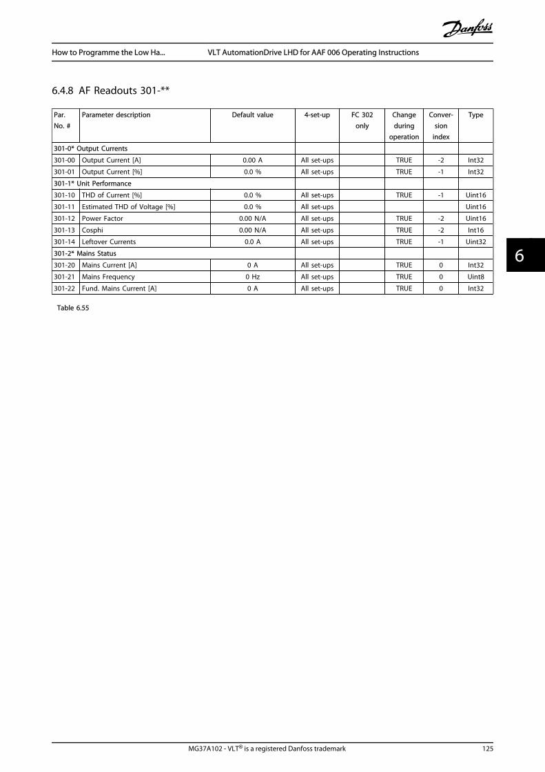
6.4.8 AF Readouts 301-**
Par.No. #
Parameter description Default value 4-set-up FC 302only
Changeduring
operation
Conver-sion
index
Type
301-0* Output Currents
301-00 Output Current [A] 0.00 A All set-ups TRUE -2 Int32
301-01 Output Current [%] 0.0 % All set-ups TRUE -1 Int32
301-1* Unit Performance
301-10 THD of Current [%] 0.0 % All set-ups TRUE -1 Uint16
301-11 Estimated THD of Voltage [%] 0.0 % All set-ups Uint16
301-12 Power Factor 0.00 N/A All set-ups TRUE -2 Uint16
301-13 Cosphi 0.00 N/A All set-ups TRUE -2 Int16
301-14 Leftover Currents 0.0 A All set-ups TRUE -1 Uint32
301-2* Mains Status
301-20 Mains Current [A] 0 A All set-ups TRUE 0 Int32
301-21 Mains Frequency 0 Hz All set-ups TRUE 0 Uint8
301-22 Fund. Mains Current [A] 0 A All set-ups TRUE 0 Int32
Table 6.55
How to Programme the Low Ha... VLT AutomationDrive LHD for AAF 006 Operating Instructions
MG37A102 - VLT® is a registered Danfoss trademark 125
6 6

7 RS-485 Installation and Set-up
RS-485 is a two-wire bus interface compatible with multi-drop network topology, i.e. nodes can be connected as abus, or via drop cables from a common trunk line. A totalof 32 nodes can be connected to one network segment.Repeaters divide network segments.
NOTEEach repeater functions as a node within the segment inwhich it is installed. Each node connected within a givennetwork must have a unique node address, across allsegments.
Terminate each segment at both ends, using either thetermination switch (S801) of the frequency converters or abiased termination resistor network. Always use screenedtwisted pair (STP) cable for bus cabling, and always followgood common installation practice.Low-impedance earth connection of the screen at everynode is important, including at high frequencies. Thus,connect a large surface of the screen to earth, for examplewith a cable clamp or a conductive cable gland. It may benecessary to apply potential-equalizing cables to maintainthe same earth potential throughout the network - partic-ularly in installations with long cables.To prevent impedance mismatch, always use the sametype of cable throughout the entire network. Whenconnecting a motor to the frequency converters, alwaysuse screened motor cable.
Cable: Screened twisted pair (STP)
Impedance: 120 Ω
Cable length:Max. 1200 m (including drop lines)Max. 500 m station-to-station
Table 7.1
7.1.1 Network Connection
One or more frequency converters can be connected to acontrol (or master) using the RS-485 standardised interface.Terminal 68 is connected to the P signal (TX+, RX+), whileterminal 69 is connected to the N signal (TX-,RX-).
If more than one frequency converter is connected to amaster, use parallel connections.
130B
A06
0.11
68 69 68 69 68 69
RS 485
RS 232USB
+
-
Illustration 7.1
In order to avoid potential equalizing currents in thescreen, earth the cable screen via terminal 61, which isconnected to the frame via an RC link.
130B
B021
.10
12 13 18 19 27 29 32 33 20 37
Remove jumper to enable Safe Stop
61 68 69 39 42 50 53 54 55
Illustration 7.2 Control Card Terminals
The RS-485 bus must be terminated by a resistor networkat both ends. For this purpose, set switch S801 on thecontrol card for "ON".For more information, see 4.8.2 Switches S201, S202, andS801 .
Communication protocol must be set to 8-30 Protocol.
RS-485 Installation and Set... VLT AutomationDrive LHD for AAF 006 Operating Instructions
126 MG37A102 - VLT® is a registered Danfoss trademark
77

7.1.2 EMC Precautions
The following EMC precautions are recommended in orderto achieve interference-free operation of the RS-485network.
Relevant national and local regulations, for exampleregarding protective earth connection, must be observed.The RS-485 communication cable must be kept away frommotor and brake resistor cables to avoid coupling of highfrequency noise from one cable to another. Normally adistance of 200 mm (8 inches) is sufficient, but keeping thegreatest possible distance between the cables is generallyrecommended, especially where cables run in parallel overlong distances. When crossing is unavoidable, the RS-485cable must cross motor and brake resistor cables at anangle of 90 degrees.
Fiel
dbus
cab
le
Min.200mm
90° crossing
130B
A08
0.11
Illustration 7.3
The FC protocol, also referred to as FC bus or Standardbus, is the Danfoss standard fieldbus. It defines an accesstechnique according to the master-slave principle forcommunications via a serial bus.One master and a maximum of 126 slaves can beconnected to the bus. The master selects the individualslaves via an address character in the telegram. A slaveitself can never transmit without first being requested todo so, and direct message transfer between the individualslaves is not possible. Communications occur in the half-duplex mode.
The master function cannot be transferred to another node(single-master system).
The physical layer is RS-485, thus utilizing the RS-485 portbuilt into the frequency converter. The FC protocolsupports different telegram formats:
• A short format of 8 bytes for process data.
• A long format of 16 bytes that also includes aparameter channel.
• A format used for texts.
7.2 Network Configuration
7.2.1 Set-up
Set the following parameters to enable the FC protocol forthe frequency converter.
Parameter Number Setting
8-30 Protocol FC
8-31 Address 1 - 126
8-32 FC Port Baud Rate 2400 - 115200
8-33 Parity / Stop Bits Even parity, 1 stop bit (default)
Table 7.2
7.3 FC Protocol Message Framing Structure
7.3.1 Content of a Character (byte)
Each character transferred begins with a start bit. Then 8data bits are transferred, corresponding to a byte. Eachcharacter is secured via a parity bit. This bit is set at "1"when it reaches parity. Parity is when there is an equalnumber of 1s in the 8 data bits and the parity bit in total.A stop bit completes a character, thus consisting of 11 bitsin all.
0 1 32 4 5 6 7
195N
A03
6.10
Startbit
Even StopParity bit
Illustration 7.4
7.3.2 Telegram Structure
Each telegram has the following structure:
1. Start character (STX)=02 Hex
2. A byte denoting the telegram length (LGE)
3. A byte denoting the frequency converter address(ADR)
RS-485 Installation and Set... VLT AutomationDrive LHD for AAF 006 Operating Instructions
MG37A102 - VLT® is a registered Danfoss trademark 127
7 7
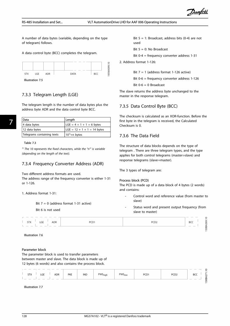
A number of data bytes (variable, depending on the typeof telegram) follows.
A data control byte (BCC) completes the telegram.
STX LGE ADR DATA BCC
195N
A09
9.10
Illustration 7.5
7.3.3 Telegram Length (LGE)
The telegram length is the number of data bytes plus theaddress byte ADR and the data control byte BCC.
Data Length
4 data bytes LGE = 4 + 1 + 1 = 6 bytes
12 data bytes LGE = 12 + 1 + 1 = 14 bytes
Telegrams containing texts 101)+n bytes
Table 7.3
1) The 10 represents the fixed characters, while the “n’” is variable(depending on the length of the text).
7.3.4 Frequency Converter Address (ADR)
Two different address formats are used.The address range of the frequency converter is either 1-31or 1-126.
1. Address format 1-31:
Bit 7 = 0 (address format 1-31 active)
Bit 6 is not used
Bit 5 = 1: Broadcast, address bits (0-4) are notused
Bit 5 = 0: No Broadcast
Bit 0-4 = frequency converter address 1-31
2. Address format 1-126:
Bit 7 = 1 (address format 1-126 active)
Bit 0-6 = frequency converter address 1-126
Bit 0-6 = 0 Broadcast
The slave returns the address byte unchanged to themaster in the response telegram.
7.3.5 Data Control Byte (BCC)
The checksum is calculated as an XOR-function. Before thefirst byte in the telegram is received, the CalculatedChecksum is 0.
7.3.6 The Data Field
The structure of data blocks depends on the type oftelegram . There are three telegram types, and the typeapplies for both control telegrams (master⇒slave) andresponse telegrams (slave⇒master).
The 3 types of telegram are:
Process block (PCD)The PCD is made up of a data block of 4 bytes (2 words)and contains:
- Control word and reference value (from master toslave)
- Status word and present output frequency (fromslave to master)
ADRLGESTX PCD1 PCD2 BCC
130B
A26
9.10
Illustration 7.6
Parameter blockThe parameter block is used to transfer parametersbetween master and slave. The data block is made up of12 bytes (6 words) and also contains the process block.
PKE INDADRLGESTX PCD1 PCD2 BCC
130B
A27
1.10
PWEhigh PWElow
Illustration 7.7
RS-485 Installation and Set... VLT AutomationDrive LHD for AAF 006 Operating Instructions
128 MG37A102 - VLT® is a registered Danfoss trademark
77

Text blockThe text block is used to read or write texts via the datablock.
PKE IND
130B
A27
0.10
ADRLGESTX PCD1 PCD2 BCCCh1 Ch2 Chn
Illustration 7.8
7.3.7 The PKE Field
The PKE field contains two sub-fields: Parameter commandand response AK, and Parameter number PNU:
15 14 13 12 11 10 9 8 7 6 5 4 3 2 1 0
130B
A26
8.10
PKE IND PWEhigh PWElow
AK PNU
Para
met
er
com
man
ds
and
repl
ies
Para
met
ernu
mbe
r
Illustration 7.9
Bits no. 12-15 transfer parameter commands from masterto slave and return processed slave responses to themaster.
Parameter commands master ⇒ slave
Bit no. Parameter command
15 14 13 12
0 0 0 0 No command
0 0 0 1 Read parameter value
0 0 1 0 Write parameter value in RAM (word)
0 0 1 1 Write parameter value in RAM (double word)
1 1 0 1 Write parameter value in RAM and EEprom (double word)
1 1 1 0 Write parameter value in RAM and EEprom (word)
1 1 1 1 Read/write text
Table 7.4
Response slave ⇒master
Bit no. Response
15 14 13 12
0 0 0 0 No response
0 0 0 1 Parameter value transferred (word)
0 0 1 0 Parameter value transferred (double word)
0 1 1 1 Command cannot be performed
1 1 1 1 text transferred
Table 7.5
RS-485 Installation and Set... VLT AutomationDrive LHD for AAF 006 Operating Instructions
MG37A102 - VLT® is a registered Danfoss trademark 129
7 7
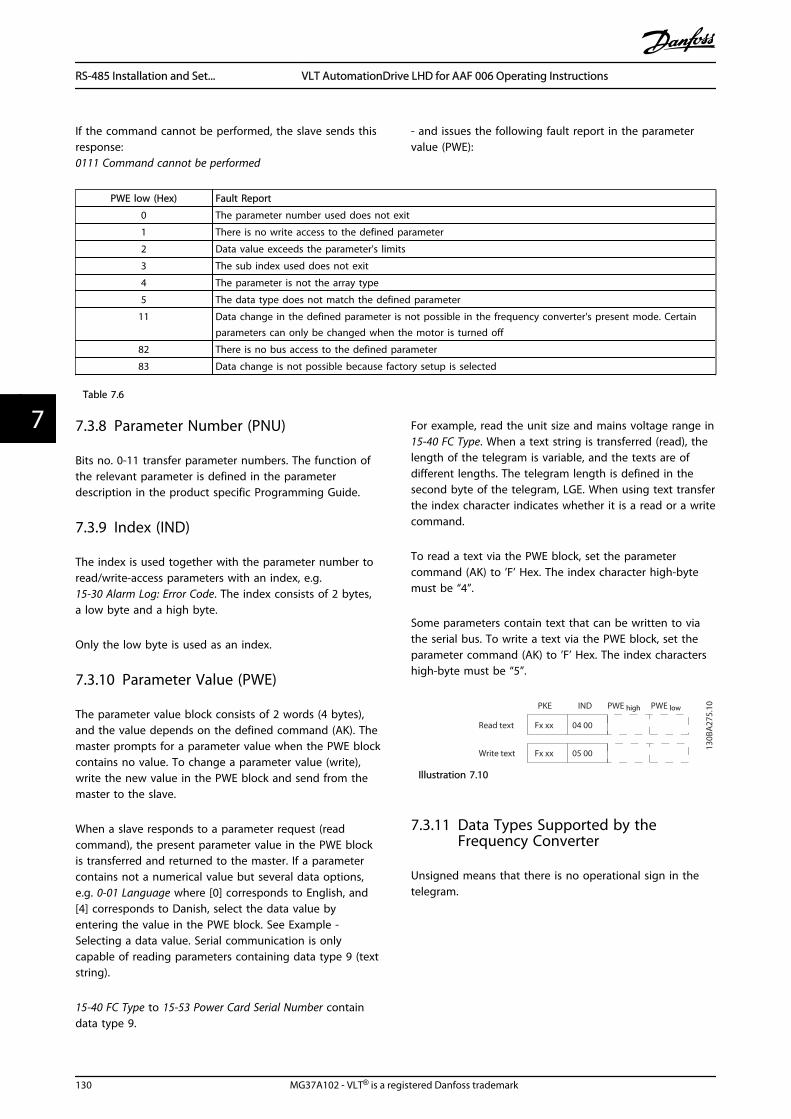
If the command cannot be performed, the slave sends thisresponse:0111 Command cannot be performed
- and issues the following fault report in the parametervalue (PWE):
PWE low (Hex) Fault Report
0 The parameter number used does not exit
1 There is no write access to the defined parameter
2 Data value exceeds the parameter's limits
3 The sub index used does not exit
4 The parameter is not the array type
5 The data type does not match the defined parameter
11 Data change in the defined parameter is not possible in the frequency converter's present mode. Certainparameters can only be changed when the motor is turned off
82 There is no bus access to the defined parameter
83 Data change is not possible because factory setup is selected
Table 7.6
7.3.8 Parameter Number (PNU)
Bits no. 0-11 transfer parameter numbers. The function ofthe relevant parameter is defined in the parameterdescription in the product specific Programming Guide.
7.3.9 Index (IND)
The index is used together with the parameter number toread/write-access parameters with an index, e.g.15-30 Alarm Log: Error Code. The index consists of 2 bytes,a low byte and a high byte.
Only the low byte is used as an index.
7.3.10 Parameter Value (PWE)
The parameter value block consists of 2 words (4 bytes),and the value depends on the defined command (AK). Themaster prompts for a parameter value when the PWE blockcontains no value. To change a parameter value (write),write the new value in the PWE block and send from themaster to the slave.
When a slave responds to a parameter request (readcommand), the present parameter value in the PWE blockis transferred and returned to the master. If a parametercontains not a numerical value but several data options,e.g. 0-01 Language where [0] corresponds to English, and[4] corresponds to Danish, select the data value byentering the value in the PWE block. See Example -Selecting a data value. Serial communication is onlycapable of reading parameters containing data type 9 (textstring).
15-40 FC Type to 15-53 Power Card Serial Number containdata type 9.
For example, read the unit size and mains voltage range in15-40 FC Type. When a text string is transferred (read), thelength of the telegram is variable, and the texts are ofdifferent lengths. The telegram length is defined in thesecond byte of the telegram, LGE. When using text transferthe index character indicates whether it is a read or a writecommand.
To read a text via the PWE block, set the parametercommand (AK) to ’F’ Hex. The index character high-bytemust be “4”.
Some parameters contain text that can be written to viathe serial bus. To write a text via the PWE block, set theparameter command (AK) to ’F’ Hex. The index charactershigh-byte must be “5”.
PWE high PWE low
Read text
Write text
130B
A27
5.10PKE IND
Fx xx 04 00
Fx xx 05 00
Illustration 7.10
7.3.11 Data Types Supported by theFrequency Converter
Unsigned means that there is no operational sign in thetelegram.
RS-485 Installation and Set... VLT AutomationDrive LHD for AAF 006 Operating Instructions
130 MG37A102 - VLT® is a registered Danfoss trademark
77
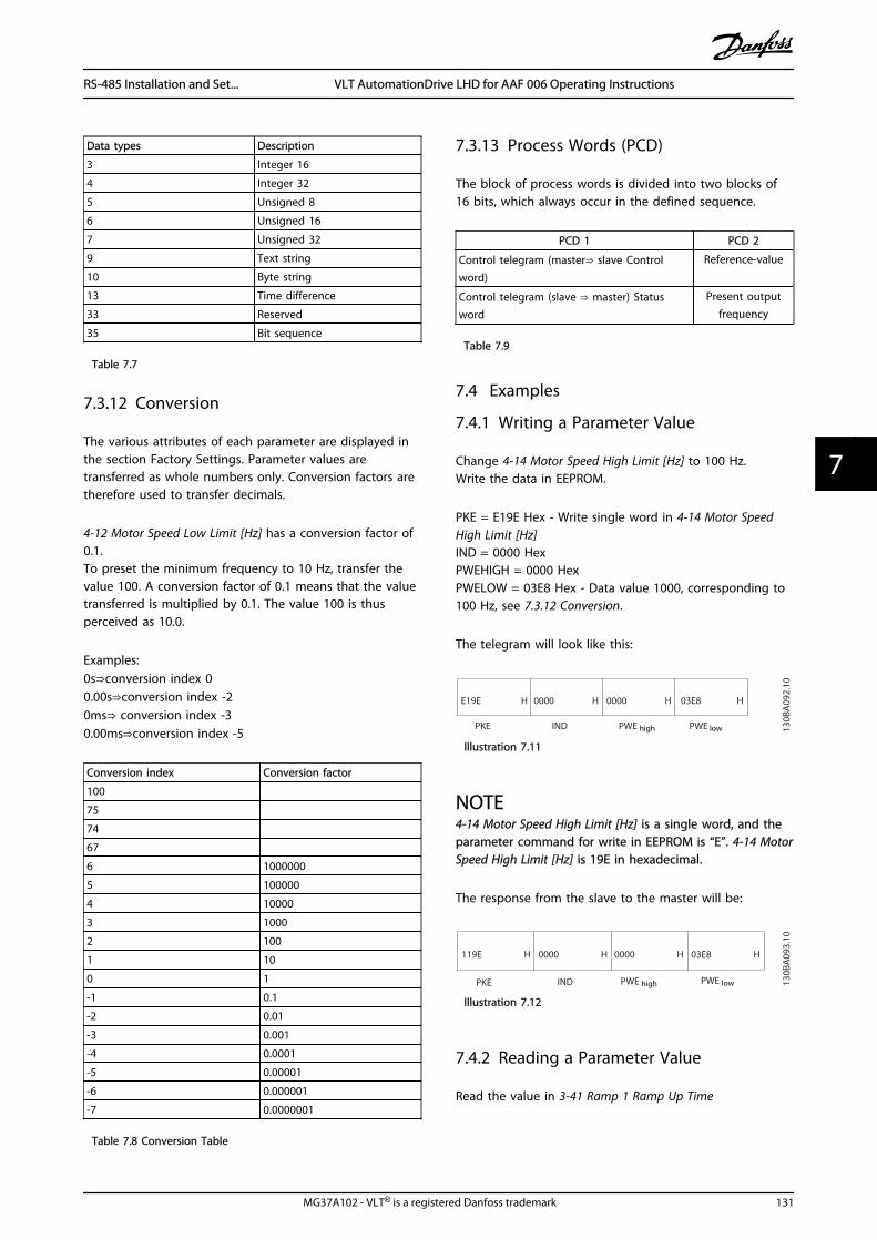
Data types Description
3 Integer 16
4 Integer 32
5 Unsigned 8
6 Unsigned 16
7 Unsigned 32
9 Text string
10 Byte string
13 Time difference
33 Reserved
35 Bit sequence
Table 7.7
7.3.12 Conversion
The various attributes of each parameter are displayed inthe section Factory Settings. Parameter values aretransferred as whole numbers only. Conversion factors aretherefore used to transfer decimals.
4-12 Motor Speed Low Limit [Hz] has a conversion factor of0.1.To preset the minimum frequency to 10 Hz, transfer thevalue 100. A conversion factor of 0.1 means that the valuetransferred is multiplied by 0.1. The value 100 is thusperceived as 10.0.
Examples:0s⇒conversion index 00.00s⇒conversion index -20ms⇒ conversion index -30.00ms⇒conversion index -5
Conversion index Conversion factor
100
75
74
67
6 1000000
5 100000
4 10000
3 1000
2 100
1 10
0 1
-1 0.1
-2 0.01
-3 0.001
-4 0.0001
-5 0.00001
-6 0.000001
-7 0.0000001
Table 7.8 Conversion Table
7.3.13 Process Words (PCD)
The block of process words is divided into two blocks of16 bits, which always occur in the defined sequence.
PCD 1 PCD 2
Control telegram (master⇒ slave Controlword)
Reference-value
Control telegram (slave ⇒ master) Statusword
Present outputfrequency
Table 7.9
7.4 Examples
7.4.1 Writing a Parameter Value
Change 4-14 Motor Speed High Limit [Hz] to 100 Hz.Write the data in EEPROM.
PKE = E19E Hex - Write single word in 4-14 Motor SpeedHigh Limit [Hz]IND = 0000 HexPWEHIGH = 0000 HexPWELOW = 03E8 Hex - Data value 1000, corresponding to100 Hz, see 7.3.12 Conversion.
The telegram will look like this:
E19E H
PKE IND PWE high PWE low
0000 H 0000 H 03E8 H
130B
A09
2.10
Illustration 7.11
NOTE4-14 Motor Speed High Limit [Hz] is a single word, and theparameter command for write in EEPROM is “E”. 4-14 MotorSpeed High Limit [Hz] is 19E in hexadecimal.
The response from the slave to the master will be:
119E H
PKE IND PWE high PWE low
0000 H 0000 H 03E8 H
130B
A09
3.10
Illustration 7.12
7.4.2 Reading a Parameter Value
Read the value in 3-41 Ramp 1 Ramp Up Time
RS-485 Installation and Set... VLT AutomationDrive LHD for AAF 006 Operating Instructions
MG37A102 - VLT® is a registered Danfoss trademark 131
7 7

PKE = 1155 Hex - Read parameter value in 3-41 Ramp 1Ramp Up TimeIND = 0000 HexPWEHIGH = 0000 HexPWELOW = 0000 Hex
1155 H
PKE IND PWE high PWE low
0000 H 0000 H 0000 H
130B
A09
4.10
Illustration 7.13
If the value in 3-41 Ramp 1 Ramp Up Time is 10 s, theresponse from the slave to the master will be:
130B
A26
7.10
1155 H
PKE IND
0000 H 0000 H 03E8 H
PWE high PWE low
Illustration 7.14
3E8 Hex corresponds to 1000 decimal. The conversionindex for 3-41 Ramp 1 Ramp Up Time is -2, i.e. 0.01.3-41 Ramp 1 Ramp Up Time is of the type Unsigned 32.
7.5 How to Access Parameters
7.5.1 Parameter Handling
The PNU (Parameter Number) is translated from theregister address contained in the Modbus read or writemessage. The parameter number is translated to Modbusas (10 x parameter number) DECIMAL.
7.5.2 Storage of Data
The Coil 65 decimal determines whether data written tothe telegram are stored in EEPROM and RAM (coil 65 = 1)or only in RAM (coil 65 = 0).
7.5.3 IND
The array index is set in Holding Register 9 and used whenaccessing array parameters.
7.5.4 Text Blocks
Parameters stored as text strings are accessed in the sameway as the other parameters. The maximum text block sizeis 20 characters. If a read request for a parameter is formore characters than the parameter stores, the response istruncated. If the read request for a parameter is for fewercharacters than the parameter stores, the response is spacefilled.
7.5.5 Conversion Factor
The different attributes for each parameter can be seen inthe section on factory settings. Since a parameter valuecan only be transferred as a whole number, a conversionfactor must be used to transfer decimals.
7.5.6 Parameter Values
Standard Data TypesStandard data types are int16, int32, uint8, uint16 anduint32. They are stored as 4x registers (40001 – 4FFFF). Theparameters are read using function 03HEX "Read HoldingRegisters." Parameters are written using the function 6HEX"Preset Single Register" for 1 register (16 bits), and thefunction 10HEX "Preset Multiple Registers" for 2 registers(32 bits). Readable sizes range from 1 register (16 bits) upto 10 registers (20 characters).
Non standard Data TypesNon standard data types are text strings and are stored as4x registers (40001 – 4FFFF). The parameters are readusing function 03HEX "Read Holding Registers" and writtenusing function 10HEX "Preset Multiple Registers." Readablesizes range from 1 register (2 characters) up to 10 registers(20 characters).
RS-485 Installation and Set... VLT AutomationDrive LHD for AAF 006 Operating Instructions
132 MG37A102 - VLT® is a registered Danfoss trademark
77

8 General Specifications
Mains supply (L1, L2, L3)Supply voltage 380-480 V +5%
Mains voltage low / mains drop-out:During low mains voltage or a mains drop-out, the frequency converter continues until the intermediate circuit voltage dropsbelow the minimum stop level, which corresponds typically to 15% below the frequency converter's lowest rated supply voltage.Power-up and full torque cannot be expected at mains voltage lower than 10% below the frequency converter's lowest ratedsupply voltage.
Supply frequency 50/60 Hz ±5%Max. imbalance temporary between mains phases 3.0 % of rated supply voltageTrue Power Factor (λ) > 0.98 nominal at rated loadDisplacement Power Factor (cosφ) near unity (> 0.98)THiD < 5%Switching on input supply L1, L2, L3 (power-ups) maximum once/2 min.Environment according to EN60664-1 overvoltage category III / pollution degree 2
The unit is suitable for use on a circuit capable of delivering not more than 100.000 RMS symmetrical Amperes, 480/690 Vmaximum.
Motor output (U, V, W)Output voltage 0 - 100% of supply voltageOutput frequency 0 - 800* HzSwitching on output UnlimitedRamp times 1 - 3600 s
* Voltage and power dependent
Torque characteristicsStarting torque (Constant torque) maximum 110% for 1 min.*
Starting torque maximum 135% up to 0.5 s*
Overload torque (Constant torque) maximum 110% for 1 min.*
*Percentage relates to the frequency converter's nominal torque.
Cable lengths and cross sectionsMax. motor cable length, screened/armoured 150 mMax. motor cable length, unscreened/unarmoured 300 mMax. cross section to motor, mains, load sharing and brake *Maximum cross section to control terminals, rigid wire 1.5 mm2/16 AWG (2 x 0.75 mm2)Maximum cross section to control terminals, flexible cable 1 mm2/18 AWGMaximum cross section to control terminals, cable with enclosed core 0.5 mm2/20 AWGMinimum cross section to control terminals 0.25 mm2
* See 8.1.1 Mains Supply 3x380-480 V AC - High Power for more information!
Digital inputsProgrammable digital inputs 4 (6)Terminal number 18, 19, 27 1), 29 1), 32, 33,Logic PNP or NPNVoltage level 0 - 24 V DCVoltage level, logic'0' PNP < 5 V DCVoltage level, logic'1' PNP > 10 V DCVoltage level, logic '0' NPN > 19 V DCVoltage level, logic '1' NPN < 14 V DCMaximum voltage on input 28 V DCInput resistance, Ri approx. 4 kΩ
All digital inputs are galvanically isolated from the supply voltage (PELV) and other high-voltage terminals.1) Terminals 27 and 29 can also be programmed as output.
General Specifications VLT AutomationDrive LHD for AAF 006 Operating Instructions
MG37A102 - VLT® is a registered Danfoss trademark 133
8 8

Analog inputsNumber of analog inputs 2Terminal number 53, 54Modes Voltage or currentMode select Switch S201 and switch S202Voltage mode Switch S201/switch S202 = OFF (U)Voltage level 0 to + 10 V (scaleable)Input resistance, Ri approx. 10 kΩMax. voltage ± 20 VCurrent mode Switch S201/switch S202 = ON (I)Current level 0/4 to 20 mA (scaleable)Input resistance, Ri approx. 200 ΩMax. current 30 mAResolution for analog inputs 10 bit (+ sign)Accuracy of analog inputs Max. error 0.5% of full scaleBandwidth 200 Hz
The analog inputs are galvanically isolated from the supply voltage (PELV) and other high-voltage terminals.
Mains
Functionalisolation
PELV isolation
Motor
DC-Bus
Highvoltage
Control+24V
RS485
18
37
130B
A11
7.10
Illustration 8.1
Pulse inputsProgrammable pulse inputs 2Terminal number pulse 29, 33Max. frequency at terminal, 29, 33 110 kHz (Push-pull driven)Max. frequency at terminal, 29, 33 5 kHz (open collector)Min. frequency at terminal 29, 33 4 HzVoltage level see section on Digital inputMaximum voltage on input 28 V DCInput resistance, Ri approx. 4 kΩPulse input accuracy (0.1-1 kHz) Max. error: 0.1% of full scaleAnalog outputNumber of programmable analog outputs 1Terminal number 42Current range at analog output 0/4 - 20 mAMax. resistor load to common at analog output 500 ΩAccuracy on analog output Max. error: 0.8% of full scaleResolution on analog output 8 bit
The analog output is galvanically isolated from the supply voltage (PELV) and other high-voltage terminals.
Control card, RS-485 serial communicationTerminal number 68 (P,TX+, RX+), 69 (N,TX-, RX-)Terminal number 61 Common for terminals 68 and 69
The RS-485 serial communication circuit is functionally seated from other central circuits and galvanically isolated from thesupply voltage (PELV).
General Specifications VLT AutomationDrive LHD for AAF 006 Operating Instructions
134 MG37A102 - VLT® is a registered Danfoss trademark
88

Digital outputProgrammable digital/pulse outputs 2Terminal number 27, 29 1)
Voltage level at digital/frequency output 0-24 VMax. output current (sink or source) 40 mAMax. load at frequency output 1 kΩMax. capacitive load at frequency output 10 nFMinimum output frequency at frequency output 0 HzMaximum output frequency at frequency output 32 kHzAccuracy of frequency output Max. error: 0.1% of full scaleResolution of frequency outputs 12 bit
1) Terminal 27 and 29 can also be programmed as input.
The digital output is galvanically isolated from the supply voltage (PELV) and other high-voltage terminals.
Control card, 24 V DC outputTerminal number 12, 13Max. load 200 mA
The 24 V DC supply is galvanically isolated from the supply voltage (PELV), but has the same potential as the analog and digitalinputs and outputs.
Relay outputsProgrammable relay outputs 2Relay 01 Terminal number 1-3 (break), 1-2 (make)Max. terminal load (AC-1)1) on 1-3 (NC), 1-2 (NO) (Resistive load) 240 V AC, 2AMax. terminal load (AC-15)1) (Inductive load @ cosφ 0.4) 240 V AC, 0.2 AMax. terminal load (DC-1)1) on 1-2 (NO), 1-3 (NC) (Resistive load) 60 V DC, 1 AMax. terminal load (DC-13)1) (Inductive load) 24 V DC, 0.1 ARelay 02 Terminal number 4-6 (break), 4-5 (make)Max. terminal load (AC-1)1) on 4-5 (NO) (Resistive load)2)3) 400 V AC, 2 AMax. terminal load (AC-15)1) on 4-5 (NO) (Inductive load @ cosφ 0.4) 240 V AC, 0.2 AMax. terminal load (DC-1)1) on 4-5 (NO) (Resistive load) 80 V DC, 2 AMax. terminal load (DC-13)1) on 4-5 (NO) (Inductive load) 24 V DC, 0.1 AMax. terminal load (AC-1)1) on 4-6 (NC) (Resistive load) 240 V AC, 2 AMax. terminal load (AC-15)1) on 4-6 (NC) (Inductive load @ cosφ 0.4) 240 V AC, 0.2 AMax. terminal load (DC-1)1) on 4-6 (NC) (Resistive load) 50 V DC, 2 AMax. terminal load (DC-13)1) on 4-6 (NC) (Inductive load) 24 V DC, 0.1 AMin. terminal load on 1-3 (NC), 1-2 (NO), 4-6 (NC), 4-5 (NO) 24 V DC 10 mA, 24 V AC 20 mAEnvironment according to EN 60664-1 overvoltage category III/pollution degree 2
1) IEC 60947 parts 4 and 5The relay contacts are galvanically isolated from the rest of the circuit by reinforced isolation (PELV).2) Overvoltage Category II3) UL applications 300 V AC 2 A
Control card, 10 V DC outputTerminal number 50Output voltage 10.5 V ±0.5 VMax. load 25 mA
The 10 V DC supply is galvanically isolated from the supply voltage (PELV) and other high-voltage terminals.
Control characteristicsResolution of output frequency at 0æ-æ1000 Hz +/- 0.003 HzSystem response time (terminals 18, 19, 27, 29, 32, 33) ≤ 2 msSpeed control range (open loop) 1:100 of synchronous speedSpeed accuracy (open loop) 30æ-æ4000 rpm: Maximum error of ±8 rpm
All control characteristics are based on a 4-pole asynchronous motor
General Specifications VLT AutomationDrive LHD for AAF 006 Operating Instructions
MG37A102 - VLT® is a registered Danfoss trademark 135
8 8

SurroundingsEnclosure, frame size D and E IP21, IP54 (hybrid)Enclosure, frame size F IP21, IP54 (hybrid)Vibration test 0.7 gRelative humidity 5%-95%(IEC 721-3-3; Class 3K3 (non-condensing) during operationAggressive environment (IEC 60068-2-43) H2S test class kDTest method according to IEC 60068-2-43 H2S (10 days)Ambient temperature (at 60 AVM switching mode)- with derating max. 55° C1)
- with full output power, typical EFF2 motors max. 50° C1)
- at full continuous FC output current max. 45° C1)
1) For more information on derating see the Design Guide, section on Special Conditions.
Minimum ambient temperature during full-scale operation 0° CMinimum ambient temperature at reduced performance - 10° CTemperature during storage/transport -25 - +65/70° CMaximum altitude above sea level without derating 1000 mMaximum altitude above sea level with derating 3000 m
Derating for high altitude, see section on special conditions
EMC standards, Emission EN 61800-3, EN 61000-6-3/4, EN 55011, IEC 61800-3
EMC standards, ImmunityEN 61800-3, EN 61000-6-1/2,
EN 61000-4-2, EN 61000-4-3, EN 61000-4-4, EN 61000-4-5, EN 61000-4-6
See section on special conditions!
Control card performanceScan interval 5 msControl card, USB serial communicationUSB standard 1.1 (Full speed)USB plug USB type B “device” plug
CAUTIONConnection to PC is carried out via a standard host/device USB cable.The USB connection is galvanically isolated from the supply voltage (PELV) and other high-voltage terminals.The USB connection is not galvanically isolated from protection earth. Use only isolated laptop/PC as connection to the USBconnector on the frequency converter or an isolated USB cable/converter.
Protection and Features:
• Electronic thermal motor protection against overload.
• Temperature monitoring of the heatsink ensures that the frequency converter trips if the temperature reaches apredefined level. An overload temperature cannot be reset until the temperature of the heatsink is below thevalues stated in the tables on the following pages (Guideline - these temperatures may vary for different powersizes, frame sizes, enclosure ratings etc.).
• The frequency converter is protected against short-circuits on motor terminals U, V, W.
• If a mains phase is missing, the frequency converter trips or issues a warning (depending on the load).
• Monitoring of the intermediate circuit voltage ensures that the frequency converter trips if the intermediate circuitvoltage is too low or too high.
• The frequency converter is protected against earth faults on motor terminals U, V, W.
General Specifications VLT AutomationDrive LHD for AAF 006 Operating Instructions
136 MG37A102 - VLT® is a registered Danfoss trademark
88

8.1.1 Mains Supply 3x380-480 V AC - High Power
Mains Supply 3x380-480 VACP132 P160 P200
High/ Normal Load* HO NO HO NO HO NO
130B
A23
0.10
Typical Shaft output at 400 V[kW] 132 160 160 200 200 250
Typical Shaft output at 460 V[HP] 200 250 250 300 300 350
Typical Shaft output at 480 V[kW] 160 200 200 250 250 315
Enclosure IP21 D13 D13 D13Enclosure IP54 D13 D13 D13Output currentContinuous(at 400 V) [A] 260 315 315 395 395 480
Intermittent (60 s overload)(at 400 V) [A] 390 347 473 435 593 528
Continuous(at 460/ 480 V) [A] 240 302 302 361 361 443
Intermittent (60 s overload)(at 460/ 480 V) [A] 360 332 453 397 542 487
Continuous KVA(at 400 V) [KVA] 180 218 218 274 274 333
Continuous KVA(at 460 V) [KVA] 191 241 241 288 288 353
Continuous KVA(at 480 V) [KVA] 208 262 262 313 313 384
Max. input current
130B
A22
9.10
Continuous(at 400 V ) [A] 251 304 304 381 381 463
Continuous(at 460/ 480 V) [A] 231 291 291 348 348 427
Max. cable size, mains motor,brake and load share [mm2
(AWG2))]
2x185(2x300 mcm)
2x185(2x300 mcm)
2x185(2x300 mcm)
Max. external mains fuses [A]1 400 500 630
Estimated motor power lossat 400 V [W] 4) 4029 5130 5621
Estimated motor power lossat 460 V [W] 3892 4646 5126
Estimated filter losses, 400 V 4954 5714 6234Estimated filter losses, 480 V 5279 5819 6681Weight,enclosure IP21, IP54 [kg] 380 380 406
Efficiency4) 0.96Output frequency 0-800 HzHeatsink overtemp. trip 110° C 110° C 110° CPower card ambient trip 60° C
* High overload = 160% torque during 60 s, Normal overload = 110% torque during 60 s
Table 8.1
General Specifications VLT AutomationDrive LHD for AAF 006 Operating Instructions
MG37A102 - VLT® is a registered Danfoss trademark 137
8 8

Mains Supply 3x380-480 VACP250 P315 P355 P400
High/ Normal Load* HO NO HO NO HO NO HO NO13
0BA23
0.10
Typical Shaft output at400 V [kW] 250 315 315 355 355 400 400 450
Typical Shaft output at460 V [HP] 350 450 450 500 500 600 550 600
Typical Shaft output at480 V [kW] 315 355 355 400 400 500 500 530
Enclosure IP21 E9 E9 E9 E9Enclosure IP54 E9 E9 E9 E9Output currentContinuous(at 400 V) [A] 480 600 600 658 658 745 695 800
Intermittent (60 soverload)(at 400 V) [A]
720 660 900 724 987 820 1043 880
Continuous(at 460/ 480 V) [A] 443 540 540 590 590 678 678 730
Intermittent (60 soverload)(at 460/ 480 V) [A]
665 594 810 649 885 746 1017 803
Continuous KVA(at 400 V) [KVA] 333 416 416 456 456 516 482 554
Continuous KVA(at 460 V) [KVA] 353 430 430 470 470 540 540 582
Continuous KVA(at 480 V) [KVA] 384 468 468 511 511 587 587 632
Max. input current
130B
A22
9.10
Continuous(at 400 V ) [A] 472 590 590 647 647 733 684 787
Continuous(at 460/ 480 V) [A] 436 531 531 580 580 667 667 718
Max. cable size, mains,motor and load share[mm2 (AWG2))]
4x240(4x500 mcm)
4x240(4x500 mcm)
4x240(4x500 mcm)
4x240(4x500 mcm)
Max. cable size, brake[mm2 (AWG2))
2x185(2x350 mcm)
2x185(2x350 mcm)
2x185(2x350 mcm)
2x185(2x350 mcm)
Max. external mainsfuses [A] 1 700 900 900 900
Estimated motor powerlossat 400 V [W] 4)
6704 7528 8671 9469
Estimated motor powerlossat 460 V [W]
5930 6724 7820 8527
Estimated filter losses,400 V 6607 7049 7725 8234
Estimated filter losses,460 V 6670 7023 7697 8099
Weight,enclosure IP21, IP54 [kg] 596 623 646 646
Efficiency4) 0.96Output frequency 0-600 HzHeatsink overtemp. trip 110° CPower card ambient trip 68° C
* High overload = 160% torque during 60 s, Normal overload = 110% torque during 60 s
Table 8.2
General Specifications VLT AutomationDrive LHD for AAF 006 Operating Instructions
138 MG37A102 - VLT® is a registered Danfoss trademark
88

Mains Supply 3x380-480 V ACP450 P500 P560 P630
High/ Normal Load* HO NO HO NO HO NO HO NO13
0BA23
0.10
Typical Shaft output at400 V [kW] 450 500 500 560 560 630 630 710
Typical Shaft output at460 V [HP] 600 650 650 750 750 900 900 1000
Typical Shaft output at480 V [kW] 530 560 560 630 630 710 710 800
EnclosureIP21, 54 F18 F18 F18 F18Output currentContinuous(at 400 V) [A] 800 880 880 990 990 1120 1120 1260
Intermittent (60 soverload)(at 400 V) [A]
1200 968 1320 1089 1485 1232 1680 1386
Continuous(at 460/ 480 V) [A] 730 780 780 890 890 1050 1050 1160
Intermittent (60 soverload)(at 460/ 480 V) [A]
1095 858 1170 979 1335 1155 1575 1276
Continuous KVA(at 400 V) [KVA] 554 610 610 686 686 776 776 873
Continuous KVA(at 460 V) [KVA] 582 621 621 709 709 837 837 924
Continuous KVA(at 480 V) [KVA] 632 675 675 771 771 909 909 1005
Max. input current
130B
A22
9.10
Continuous(at 400 V ) [A] 779 857 857 964 964 1090 1090 1227
Continuous (at 460/ 480V) [A] 711 759 759 867 867 1022 1022 1129
Max. cable size,motor[mm2 (AWG2))]
8x150(8x300 mcm)
Max. cable size,mainsF1/F2 [mm2 (AWG2))]
8x240(8x500 mcm)
Max. cable size,mainsF3/F4 [mm2 (AWG2))]
8x456(8x900 mcm)
Max. cable size,loadsharing [mm2
(AWG2))]
4x120(4x250 mcm)
Max. cable size, brake[mm2 (AWG2))
4x185(4x350 mcm)
Max. external mains fuses[A] 1 1600 2000
Estimated motor powerlossat 400 V [W] 4)
10647 12338 13201 15436
Estimated motor powerlossat 460 V [W]
9414 11006 12353 14041
Max. panel options losses 400Weight,enclosure IP21, IP54 [kg] 2009
Weight drive section [kg] 1004Weight filter section [kg] 1005Efficiency4) 0.96Output frequency 0-600 HzHeatsink overtemp. trip 95° CPower card ambient trip 68° C
* High overload = 160% torque during 60 s, Normal overload = 110% torque during 60 s
Table 8.3
1) For type of fuse see 4.6.14 Fuses.
2) American Wire Gauge.
3) Measured using 5 m screened motor cables atrated load and rated frequency.
General Specifications VLT AutomationDrive LHD for AAF 006 Operating Instructions
MG37A102 - VLT® is a registered Danfoss trademark 139
8 8

4) The typical power loss is at nominal loadconditions and expected to be within +/-15%(tolerence relates to variety in voltage and cableconditions). Values are based on a typical motorefficiency (eff2/eff3 border line). Motors withlower efficiency will also add to the power loss inthe frequency converter and opposite. If theswitching frequency is increased comed to thedefault setting, the power losses may rise signifi-
cantly.LCP and typical control card powerconsumptions are included. Further options andcustomer load may add up to 30 W to the losses.(Though typical only 4 W extra for a fully loadedcontrol card, or options for slot A or slot B, each).Although measurements are made with state ofthe art equipment, some measurementinaccuracy must be allowed for (+/-5%).
8.2 Filter Specifications
Frame size D E F
Voltage [V] 380-480 380-480 380-480
Current, RMS [A] 120 210 330 Nominal value
Peak Current [A] 340 595 935 Amplitude value of the current
RMS overload [%] No Overload 60 s in 10 min
Response time [ms] <0.5
Settling time - reactive current control [ms] <40
Settling time - harmonic current control(filtering) [ms]
<20
Overshoot - reactive current control [%] <20
Overshoot - harmonic current control [%] <10
Table 8.4 Power Ranges (LHD with AF)
General Specifications VLT AutomationDrive LHD for AAF 006 Operating Instructions
140 MG37A102 - VLT® is a registered Danfoss trademark
88

9 Troubleshooting
9.1 Alarms and Warnings - FrequencyConverter (Right LCP)
9.1.1 Warnings/Alarm Messages
A warning or an alarm is signalled by the relevant LED onthe front of the frequency converter and indicated by acode on the display.
A warning remains active until its cause is no longerpresent. Under certain circumstances operation of themotor may still be continued. Warning messages may becritical, but are not necessarily so.
In the event of an alarm, the frequency converter will havetripped. Alarms must be reset to restart operation oncetheir cause has been rectified.
This may be done in three ways:1. By pressing [Reset].
2. Via a digital input with the “Reset” function.
3. Via serial communication/optional fieldbus.
NOTEAfter a manual reset pressing [Reset], press [Auto On] torestart the motor.
If an alarm cannot be reset, the reason may be that itscause has not been rectified, or the alarm is trip-locked(see also Table 9.1).
Alarms that are trip-locked offer additional protection,meaning that the mains supply must be switched offbefore the alarm can be reset. After being switched backon, the frequency converter is no longer blocked and maybe reset as described above once the cause has beenrectified.
Alarms that are not trip-locked can also be reset using theautomatic reset function in 14-20 Reset Mode
NOTEAutomatic wake-up is possible!
If a warning and alarm is marked against a code in thetable on the following page, this means that either awarning occurs before an alarm, or else that you canspecify whether it is a warning or an alarm that is to bedisplayed for a given fault.
This is possible, for instance, in 1-90 Motor ThermalProtection. After an alarm or trip, the motor carries oncoasting, and the alarm and warning flash. Once theproblem has been rectified, only the alarm continuesflashing until the frequency converter is reset.
No. Description Warning Alarm/Trip Alarm/Trip Lock ParameterReference
1 10 Volts low X
2 Live zero error (X) (X) 6-01 Live Zero TimeoutFunction
3 No motor (X) 1-80 Function at Stop
4 Mains phase loss (X) (X) (X) 14-12 Function atMains Imbalance
5 DC link voltage high X
6 DC link voltage low X
7 DC over-voltage X X
8 DC under voltage X X
9 Inverter overloaded X X
10 Motor ETR over temperature (X) (X) 1-90 Motor ThermalProtection
11 Motor thermistor over temperature (X) (X) 1-90 Motor ThermalProtection
12 Torque limit X X
13 Over Current X X X
14 Earth Fault X X X
15 Hardware mismatch X X
16 Short Circuit X X
Troubleshooting VLT AutomationDrive LHD for AAF 006 Operating Instructions
MG37A102 - VLT® is a registered Danfoss trademark 141
9 9
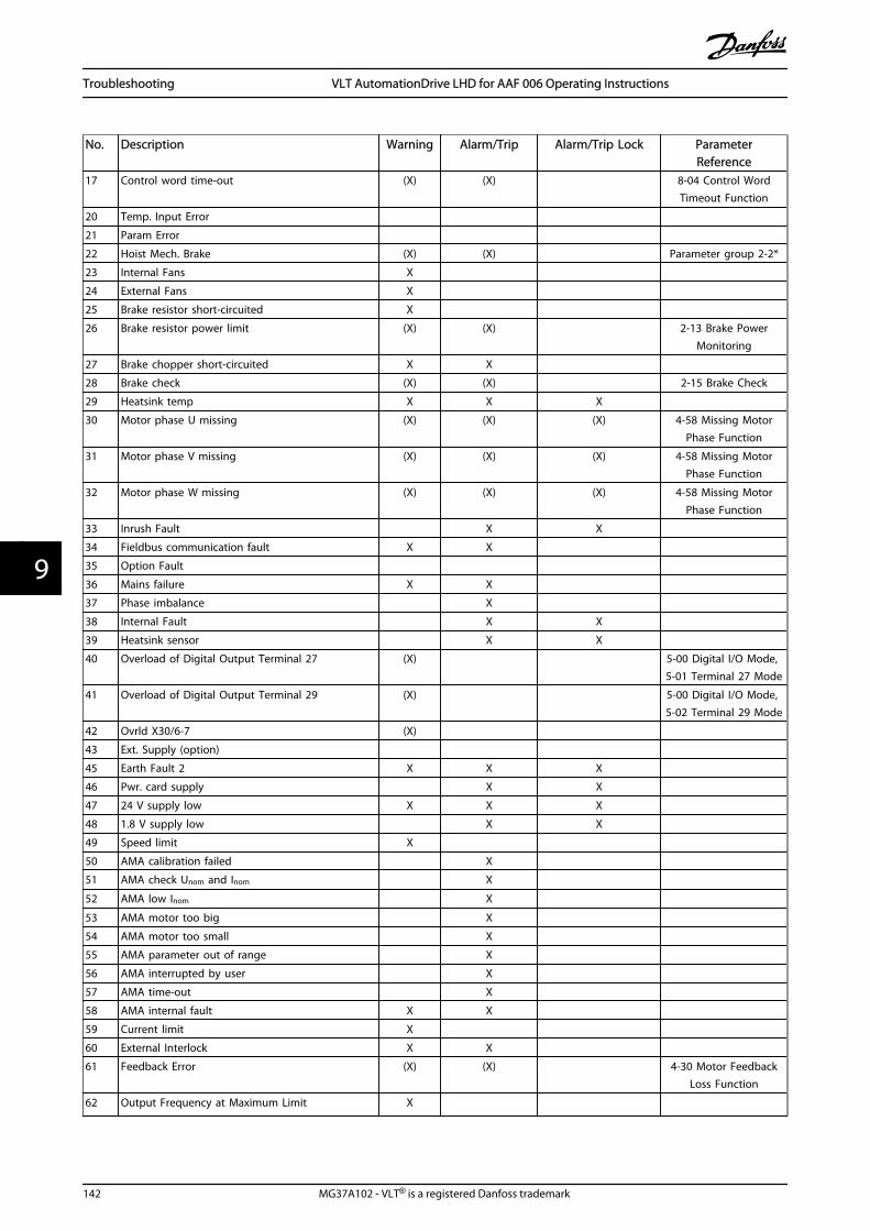
No. Description Warning Alarm/Trip Alarm/Trip Lock ParameterReference
17 Control word time-out (X) (X) 8-04 Control WordTimeout Function
20 Temp. Input Error
21 Param Error
22 Hoist Mech. Brake (X) (X) Parameter group 2-2*
23 Internal Fans X
24 External Fans X
25 Brake resistor short-circuited X
26 Brake resistor power limit (X) (X) 2-13 Brake PowerMonitoring
27 Brake chopper short-circuited X X
28 Brake check (X) (X) 2-15 Brake Check
29 Heatsink temp X X X
30 Motor phase U missing (X) (X) (X) 4-58 Missing MotorPhase Function
31 Motor phase V missing (X) (X) (X) 4-58 Missing MotorPhase Function
32 Motor phase W missing (X) (X) (X) 4-58 Missing MotorPhase Function
33 Inrush Fault X X
34 Fieldbus communication fault X X
35 Option Fault
36 Mains failure X X
37 Phase imbalance X
38 Internal Fault X X
39 Heatsink sensor X X
40 Overload of Digital Output Terminal 27 (X) 5-00 Digital I/O Mode, 5-01 Terminal 27 Mode
41 Overload of Digital Output Terminal 29 (X) 5-00 Digital I/O Mode, 5-02 Terminal 29 Mode
42 Ovrld X30/6-7 (X)
43 Ext. Supply (option)
45 Earth Fault 2 X X X
46 Pwr. card supply X X
47 24 V supply low X X X
48 1.8 V supply low X X
49 Speed limit X
50 AMA calibration failed X
51 AMA check Unom and Inom X
52 AMA low Inom X
53 AMA motor too big X
54 AMA motor too small X
55 AMA parameter out of range X
56 AMA interrupted by user X
57 AMA time-out X
58 AMA internal fault X X
59 Current limit X
60 External Interlock X X
61 Feedback Error (X) (X) 4-30 Motor FeedbackLoss Function
62 Output Frequency at Maximum Limit X
Troubleshooting VLT AutomationDrive LHD for AAF 006 Operating Instructions
142 MG37A102 - VLT® is a registered Danfoss trademark
99
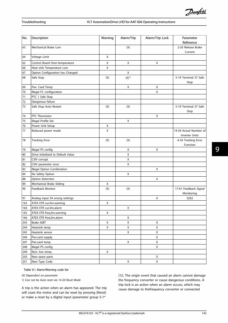
No. Description Warning Alarm/Trip Alarm/Trip Lock ParameterReference
63 Mechanical Brake Low (X) 2-20 Release BrakeCurrent
64 Voltage Limit X
65 Control Board Over-temperature X X X
66 Heat sink Temperature Low X
67 Option Configuration has Changed X
68 Safe Stop (X) (X)1) 5-19 Terminal 37 SafeStop
69 Pwr. Card Temp X X
70 Illegal FC configuration X
71 PTC 1 Safe Stop
72 Dangerous failure
73 Safe Stop Auto Restart (X) (X) 5-19 Terminal 37 SafeStop
74 PTC Thermistor X
75 Illegal Profile Sel. X
76 Power Unit Setup X
77 Reduced power mode X 14-59 Actual Number ofInverter Units
78 Tracking Error (X) (X) 4-34 Tracking ErrorFunction
79 Illegal PS config X X
80 Drive Initialized to Default Value X
81 CSIV corrupt X
82 CSIV parameter error X
83 Illegal Option Combination X
84 No Safety Option X
88 Option Detection X
89 Mechanical Brake Sliding X
90 Feedback Monitor (X) (X) 17-61 Feedback SignalMonitoring
91 Analog input 54 wrong settings X S202
163 ATEX ETR cur.lim.warning X
164 ATEX ETR cur.lim.alarm X
165 ATEX ETR freq.lim.warning X
166 ATEX ETR freq.lim.alarm X
243 Brake IGBT X X X
244 Heatsink temp X X X
245 Heatsink sensor X X
246 Pwr.card supply X
247 Pwr.card temp X X
248 Illegal PS config X
249 Rect. low temp. X
250 New spare parts X
251 New Type Code X X
Table 9.1 Alarm/Warning code list
(X) Dependent on parameter1) Can not be Auto reset via 14-20 Reset Mode
A trip is the action when an alarm has appeared. The tripwill coast the motor and can be reset by pressing [Reset]or make a reset by a digital input (parameter group 5-1*
[1]). The origin event that caused an alarm cannot damagethe frequency converter or cause dangerous conditions. Atrip lock is an action when an alarm occurs, which maycause damage to thefrequency converter or connected
Troubleshooting VLT AutomationDrive LHD for AAF 006 Operating Instructions
MG37A102 - VLT® is a registered Danfoss trademark 143
9 9

parts. A Trip Lock situation can only be reset by a powercycling.
LED indication
Warning yellow
Alarm flashing red
Trip locked yellow and red
Table 9.2
Bit Hex Dec Alarm Word Alarm Word 2 Warning Word WarningWord 2
ExtendedStatus Word
Alarm Word Extended Status Word
0 00000001 1 Brake Check (A28) ServiceTrip, Read/Write
Brake Check (W28) reserved Ramping
1 00000002 2 Heatsink temp.(A29)
ServiceTrip,(reserved)
Heatsink temp. (W29) reserved AMA Running
2 00000004 4 Earth Fault (A14) ServiceTrip,Typecode/Sparepart
Earth Fault (W14) reserved Start CW/CCWNOT start_possiblestart_possible isactive, when the DIselections [12] OR[13] are active andthe requesteddirection matches thereference sign
3 00000008 8 Ctrl.Card Temp(A65)
ServiceTrip,(reserved)
Ctrl.Card Temp (W65) reserved Slow Downslow down commandactive, e.g. via CTWbit 11 or DI
4 00000010 16 Ctrl. Word TO (A17) ServiceTrip,(reserved)
Ctrl. Word TO (W17) Catch Upcatch up commandactive, e.g. via CTWbit 12 or DI
5 00000020 32 Over Current (A13) reserved Over Current (W13) reserved Feedback Highfeedback > 4-57
6 00000040 64 Torque Limit (A12) reserved Torque Limit (W12) reserved Feedback Lowfeedback < 4-56
7 00000080 128 Motor Th Over(A11)
reserved Motor Th Over (W11) reserved Output Current Highcurrent > 4-51
8 00000100 256 Motor ETR Over(A10)
reserved Motor ETR Over (W10) reserved Output Current Lowcurrent < 4-50
9 00000200 512 Inverter Overld.(A9)
reserved Inverter Overld (W9) reserved Output Freq Highspeed > 4-53
10 00000400 1024 DC under Volt (A8) reserved DC under Volt (W8) Output Freq Lowspeed < 4-52
11 00000800 2048 DC over Volt (A7) reserved DC over Volt (W7) Brake Check OKbrake test NOT ok
12 00001000 4096 Short Circuit (A16) reserved DC Voltage Low (W6) reserved Braking MaxBrakePower >BrakePowerLimit(2-12)
13 00002000 8192 Inrush Fault (A33) reserved DC Voltage High (W5) Braking
14 00004000 16384 Mains ph. Loss (A4) reserved Mains ph. Loss (W4) Out of Speed Range
15 00008000 32768 AMA Not OK reserved No Motor (W3) OVC Active
16 00010000 65536 Live Zero Error (A2) reserved Live Zero Error (W2) AC Brake
Troubleshooting VLT AutomationDrive LHD for AAF 006 Operating Instructions
144 MG37A102 - VLT® is a registered Danfoss trademark
99
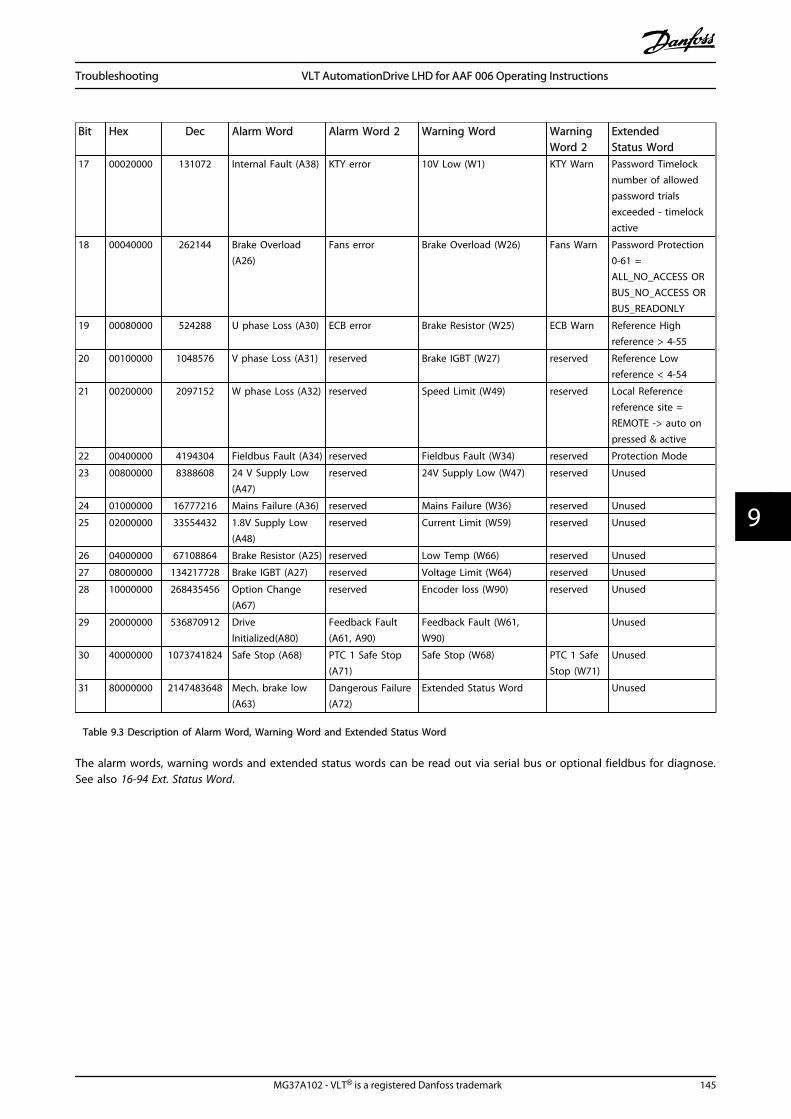
Bit Hex Dec Alarm Word Alarm Word 2 Warning Word WarningWord 2
ExtendedStatus Word
17 00020000 131072 Internal Fault (A38) KTY error 10V Low (W1) KTY Warn Password Timelocknumber of allowedpassword trialsexceeded - timelockactive
18 00040000 262144 Brake Overload(A26)
Fans error Brake Overload (W26) Fans Warn Password Protection0-61 =ALL_NO_ACCESS ORBUS_NO_ACCESS ORBUS_READONLY
19 00080000 524288 U phase Loss (A30) ECB error Brake Resistor (W25) ECB Warn Reference Highreference > 4-55
20 00100000 1048576 V phase Loss (A31) reserved Brake IGBT (W27) reserved Reference Lowreference < 4-54
21 00200000 2097152 W phase Loss (A32) reserved Speed Limit (W49) reserved Local Referencereference site =REMOTE -> auto onpressed & active
22 00400000 4194304 Fieldbus Fault (A34) reserved Fieldbus Fault (W34) reserved Protection Mode
23 00800000 8388608 24 V Supply Low(A47)
reserved 24V Supply Low (W47) reserved Unused
24 01000000 16777216 Mains Failure (A36) reserved Mains Failure (W36) reserved Unused
25 02000000 33554432 1.8V Supply Low(A48)
reserved Current Limit (W59) reserved Unused
26 04000000 67108864 Brake Resistor (A25) reserved Low Temp (W66) reserved Unused
27 08000000 134217728 Brake IGBT (A27) reserved Voltage Limit (W64) reserved Unused
28 10000000 268435456 Option Change(A67)
reserved Encoder loss (W90) reserved Unused
29 20000000 536870912 DriveInitialized(A80)
Feedback Fault(A61, A90)
Feedback Fault (W61,W90)
Unused
30 40000000 1073741824 Safe Stop (A68) PTC 1 Safe Stop(A71)
Safe Stop (W68) PTC 1 SafeStop (W71)
Unused
31 80000000 2147483648 Mech. brake low(A63)
Dangerous Failure(A72)
Extended Status Word Unused
Table 9.3 Description of Alarm Word, Warning Word and Extended Status Word
The alarm words, warning words and extended status words can be read out via serial bus or optional fieldbus for diagnose.See also 16-94 Ext. Status Word.
Troubleshooting VLT AutomationDrive LHD for AAF 006 Operating Instructions
MG37A102 - VLT® is a registered Danfoss trademark 145
9 9
9.1.2 Warnings/Alarm Messages -Frequency Converters
WARNING 1, 10 volts lowThe control card voltage is below 10 V from terminal 50.Remove some of the load from terminal 50, as the 10 Vsupply is overloaded. Max. 15 mA or minimum 590 Ω.
This condition can be caused by a short in a connectedpotentiometer or improper wiring of the potentiometer.
Troubleshooting: Remove the wiring from terminal 50. Ifthe warning clears, the problem is with the customerwiring. If the warning does not clear, replace the controlcard.
WARNING/ALARM 2, Live zero errorThis warning or alarm will only appear if programmed bythe user in 6-01 Live Zero Timeout Function. The signal onone of the analog inputs is less than 50% of the minimumvalue programmed for that input. This condition can becaused by broken wiring or faulty device sending thesignal.
Troubleshooting:Check connections on all the analog inputterminals. Control card terminals 53 and 54 forsignals, terminal 55 common. MCB 101 terminals11 and 12 for signals, terminal 10 common. MCB109 terminals 1, 3, 5 for signals, terminals 2, 4, 6common).
Check that the drive programming and switchsettings match the analog signal type.
Perform Input Terminal Signal Test.
WARNING/ALARM 3, No motorNo motor has been connected to the output of thefrequency converter. This warning or alarm will onlyappear if programmed by the user in 1-80 Function at Stop.
Troubleshooting: Check the connection between the driveand the motor.
WARNING/ALARM 4, Mains phase lossA phase is missing on the supply side, or the mainsvoltage imbalance is too high. This message also appearsfor a fault in the input rectifier on the frequency converter.Options are programmed at 14-12 Function at MainsImbalance.
Troubleshooting: Check the supply voltage and supplycurrents to the frequency converter
WARNING 5, DC link voltage highThe intermediate circuit voltage (DC) is higher than thehigh voltage warning limit. The limit is dependent on thedrive voltage rating. The frequency converter is still active.
WARNING 6, DC link voltage lowThe intermediate circuit voltage (DC) is lower than the lowvoltage warning limit. The limit is dependent on the drivevoltage rating. The frequency converter is still active.
WARNING/ALARM 7, DC overvoltageIf the intermediate circuit voltage exceeds the limit, thefrequency converter trips after a time.
Troubleshooting:Connect a brake resistor
Extend the ramp time
Change the ramp type
Activate functions in 2-10 Brake Function
Increase 14-26 Trip Delay at Inverter Fault
WARNING/ALARM 8, DC under voltageIf the intermediate circuit voltage (DC) drops below theunder voltage limit, the frequency converter checks if a 24V backup supply is connected. If no 24 V backup supply isconnected, the frequency converter trips after a fixed timedelay. The time delay varies with unit size.
Troubleshooting:Check that the supply voltage matches thefrequency converter voltage.
Perform Input voltage test
Perform soft charge and rectifier circuit test
WARNING/ALARM 9, Inverter overloadedThe frequency converter is about to cut out because of anoverload (too high current for too long). The counter forelectronic, thermal inverter protection gives a warning at98% and trips at 100%, while giving an alarm. Thefrequency converter cannot be reset until the counter isbelow 90%.The fault is that the frequency converter is overloaded bymore than 100% for too long.
Troubleshooting:Compare the output current shown on the LCPkeypad with the drive rated current.
Compare the output current shown on the LCPkeypad with measured motor current.
Display the Thermal Drive Load on the keypadand monitor the value. When running above thedrive continuous current rating, the countershould increase. When running below the drivecontinuous current rating, the counter shoulddecrease.
Note: See the derating section in the Design Guide formore details if a high switching frequency is required.
WARNING/ALARM 10, Motor overload temperatureAccording to the electronic thermal protection (ETR), themotor is too hot. Select whether the frequency convertergives a warning or an alarm when the counter reaches100% in 1-90 Motor Thermal Protection. The fault is that themotor is overloaded by more than 100% for too long.
Troubleshooting:Check if motor is over heating.
If the motor is mechanically overloaded
Troubleshooting VLT AutomationDrive LHD for AAF 006 Operating Instructions
146 MG37A102 - VLT® is a registered Danfoss trademark
99

That the motor 1-24 Motor Current is set correctly.
Motor data in 1-20 Motor Power [kW] through1-25 Motor Nominal Speed are set correctly.
The setting in 1-91 Motor External Fan.
Run AMA in 1-29 Automatic Motor Adaptation(AMA).
WARNING/ALARM 11, Motor thermistor over tempThe thermistor or the thermistor connection is discon-nected. Select whether the frequency converter gives awarning or an alarm when the counter reaches 100% in 1-90 Motor Thermal Protection.
Troubleshooting:Check if motor is over heating.
Check if the motor is mechanically overloaded.
Check that the thermistor is connected correctlybetween terminal 53 or 54 (analog voltage input)and terminal 50 (+10 V supply), or betweenterminal 18 or 19 (digital input PNP only) andterminal 50.
If a KTY sensor is used, check for correctconnection between terminal 54 and 55.
If using a thermal switch or thermistor, check theprogramming of 1-93 Thermistor Resource matchessensor wiring.
If using a KTY sensor, check the programming of1-95 KTY Sensor Type, 1-96 KTY ThermistorResource, and 1-97 KTY Threshold level matchsensor wiring.
WARNING/ALARM 12, Torque limitThe torque is higher than the value in 4-16 Torque LimitMotor Mode (in motor operation) or the torque is higherthan the value in 4-17 Torque Limit Generator Mode (inregenerative operation). 14-25 Trip Delay at Torque Limitcan be used to change this from a warning only conditionto a warning followed by an alarm.
WARNING/ALARM 13, Over CurrentThe inverter peak current limit (approx. 200% of the ratedcurrent) is exceeded. The warning lasts about 1.5 s, thenthe frequency converter trips and issues an alarm. Ifextended mechanical brake control is selected, trip can bereset externally.
Troubleshooting:This fault may be caused by shock loading or fastacceleration with high inertia loads.
Turn off the frequency converter. Check if themotor shaft can be turned.
Check that the motor size matches the frequencyconverter.
Incorrect motor data in 1-20 Motor Power [kW]through 1-25 Motor Nominal Speed.
ALARM 14, Earth (ground) faultThere is a discharge from the output phases to earth,either in the cable between the frequency converter andthe motor or in the motor itself.
Troubleshooting:Turn off the frequency converter and remove theearth fault.
Measure the resistance to ground of the motorleads and the motor with a megohmmeter tocheck for earth faults in the motor.
Perform current sensor test.
ALARM 15, Hardware mismatchA fitted option is not operational with the present controlboard hardware or software.
Record the value of the following parameters and contactyour Danfoss supplier:
15-40 FC Type
15-41 Power Section
15-42 Voltage
15-43 Software Version
15-45 Actual Typecode String
15-49 SW ID Control Card
15-50 SW ID Power Card
15-60 Option Mounted
15-61 Option SW Version
ALARM 16, Short circuitThere is short-circuiting in the motor or on the motorterminals.Turn off the frequency converter and remove the short-circuit.
WARNING/ALARM 17, Control word timeoutThere is no communication to the frequency converter.The warning will only be active when 8-04 Control WordTimeout Function is NOT set to OFF.If 8-04 Control Word Timeout Function is set to Stop andTrip, a warning appears and the frequency converter rampsdown until it trips, while giving an alarm.
Troubleshooting:Check connections on the serial communicationcable.
Increase 8-03 Control Word Timeout Time
Check operation of the communicationequipment.
Verify proper installation based on EMCrequirements.
WARNING 22, Hoist Mech. Brake:Report value will show what kind it is.0 = The torque ref. was not reached before timeout.1 = There was no brake feedback before timeout.
Troubleshooting VLT AutomationDrive LHD for AAF 006 Operating Instructions
MG37A102 - VLT® is a registered Danfoss trademark 147
9 9
WARNING 23, Internal fan faultThe fan warning function is an extra protection functionthat checks if the fan is running / mounted. The fanwarning can be disabled in 14-53 Fan Monitor ([0]Disabled).
For the D, E, and F Frame sizes, the regulated voltage tothe fans is monitored.
Troubleshooting:Check fan resistance.
Check soft charge fuses.
WARNING 24, External fan faultThe fan warning function is an extra protection functionthat checks if the fan is running / mounted. The fanwarning can be disabled in 14-53 Fan Monitor ([0]Disabled).
For the D, E, and F Frame sizes, the regulated voltage tothe fans is monitored.
Troubleshooting:Check fan resistance.
Check soft charge fuses.
WARNING 25, Brake resistor short circuitThe brake resistor is monitored during operation. If it shortcircuits, the brake function is disconnected and thewarning appears. The frequency converter still works, butwithout the brake function. Turn off the frequencyconverter and replace the brake resistor (see 2-15 BrakeCheck).
WARNING/ALARM 26, Brake resistor power limitThe power transmitted to the brake resistor is calculated:as a percentage, as a mean value over the last 120seconds, on the basis of the resistance value of the brakeresistor, and the intermediate circuit voltage. The warningis active when the dissipated braking power is higher than90%. If [2] Trip has been selected in 2-13 Brake PowerMonitoring, the frequency converter cuts out and issuesthis alarm, when the dissipated braking power is higherthan 100%.
CAUTIONThere is a risk of substantial power being transmitted tothe brake resistor if the brake transistor is short-circuited.
WARNING/ALARM 27, Brake chopper faultThe brake transistor is monitored during operation and if itshort-circuits, the brake function disconnects and issues awarning. The frequency converter is still able to run, butsince the brake transistor has short-circuited, substantialpower is transmitted to the brake resistor, even if it isinactive.Turn off the frequency converter and remove the brakeresistor.This alarm/ warning could also occur should the brakeresistor overheat. Terminal 104 to 106 are available asbrake resistor. Klixon inputs, see .
WARNING/ALARM 28, Brake check failedBrake resistor fault: the brake resistor is not connected ornot working.Check 2-15 Brake Check.
ALARM 29, Heatsink tempThe maximum temperature of the heatsink has beenexceeded. The temperature fault will not be reset until thetemperature falls below a defined heatsink temperature.The trip and reset point are different based on thefrequency converter power size.
Troubleshooting:Ambient temperature too high.
Too long motor cable.
Incorrect clearance above and below thefrequency converter.
Dirty heatsink.
Blocked air flow around the frequency converter.
Damaged heatsink fan.
For the D, E, and F Frame sizes, this alarm is based on thetemperature measured by the heatsink sensor mountedinside the IGBT modules. For the F Frame sizes, this alarmcan also be caused by the thermal sensor in the Rectifiermodule.
Troubleshooting:Check fan resistance.
Check soft charge fuses.
IGBT thermal sensor.
ALARM 30, Motor phase U missingMotor phase U between the frequency converter and themotor is missing.Turn off the frequency converter and check motor phaseU.
ALARM 31, Motor phase V missingMotor phase V between the frequency converter and themotor is missing.Turn off the frequency converter and check motor phase V.
ALARM 32, Motor phase W missingMotor phase W between the frequency converter and themotor is missing.Turn off the frequency converter and check motor phaseW.
ALARM 33, Inrush faultToo many power-ups have occurred within a short timeperiod. Let unit cool to operating temperature.
WARNING/ALARM 34, Fieldbus communication faultThe fieldbus on the communication option card is notworking.
Troubleshooting VLT AutomationDrive LHD for AAF 006 Operating Instructions
148 MG37A102 - VLT® is a registered Danfoss trademark
99
WARNING/ALARM 36, Mains failureThis warning/alarm is only active if the supply voltage tothe frequency converter is lost and 14-10 Mains Failure isNOT set to OFF. Check the fuses to the frequencyconverter.
ALARM 38, Internal faultIt may be necessary to contact your Danfoss supplier.Some typical alarm messages:
0 Serial port cannot be initialized. Serious hardwarefailure
256-258 Power EEPROM data is defect or too old
512 Control board EEPROM data is defect or too old
513 Communication time out reading EEPROM data
514 Communication time out reading EEPROM data
515 Application Orientated Control cannot recognize theEEPROM data
516 Cannot write to the EEPROM because a writecommand is on progress
517 Write command is under time out
518 Failure in the EEPROM
519 Missing or invalid Barcode data in EEPROM
783 Parameter value outside of min/max limits
1024-1279
A cantelegram that has to be sent, couldn't be sent
1281 Digital Signal Processor flash timeout
1282 Power micro software version mismatch
1283 Power EEPROM data version mismatch
1284 Cannot read Digital Signal Processor software version
1299 Option SW in slot A is too old
1300 Option SW in slot B is too old
1301 Option SW in slot C0 is too old
1302 Option SW in slot C1 is too old
1315 Option SW in slot A is not supported (not allowed)
1316 Option SW in slot B is not supported (not allowed)
1317 Option SW in slot C0 is not supported (not allowed)
1318 Option SW in slot C1 is not supported (not allowed)
1379 Option A did not respond when calculating PlatformVersion.
1380 Option B did not respond when calculating PlatformVersion.
1381 Option C0 did not respond when calculating PlatformVersion.
1382 Option C1 did not respond when calculating PlatformVersion.
1536 An exception in the Application Orientated Control isregistered. Debug information written in LCP
1792 DSP watchdog is active. Debugging of power partdata Motor Orientated Control data not transferredcorrectly
2049 Power data restarted
2064-2072
H081x: option in slot x has restarted
2080-2088
H082x: option in slot x has issued a powerup-wait
2096-2104
H083x: option in slot x has issued a legal powerup-wait
2304 Could not read any data from power EEPROM
2305 Missing SW version from power unit
2314 Missing power unit data from power unit
2315 Missing SW version from power unit
2316 Missing io_statepage from power unit
2324 Power card configuration is determined to beincorrect at power up
2325 A power card has stopped communicating whilemain power is applied
2326 Power card configuration is determined to beincorrect after the delay for power cards to register
2327 Too many power card locations have been registeredas present
2330 Power size information between the power cardsdoes not match
2561 No communication from DSP to ATACD
2562 No communication from ATACD to DSP (staterunning)
2816 Stack overflow Control board module
2817 Scheduler slow tasks
2818 Fast tasks
2819 Parameter thread
2820 LCP Stack overflow
2821 Serial port overflow
2822 USB port overflow
2836 cfListMempool to small
3072-5122
Parameter value is outside its limits
5123 Option in slot A: Hardware incompatible with Controlboard hardware
5124 Option in slot B: Hardware incompatible with Controlboard hardware
5125 Option in slot C0: Hardware incompatible withControl board hardware
5126 Option in slot C1: Hardware incompatible withControl board hardware
5376-6231
Out of memory
Table 9.4
ALARM 39, Heatsink sensorNo feedback from the heatsink temperature sensor.
The signal from the IGBT thermal sensor is not available onthe power card. The problem could be on the power card,on the gate drive card, or the ribbon cable between thepower card and gate drive card.
WARNING 40, Overload of Digital Output Terminal 27Check the load connected to terminal 27 or remove short-circuit connection. Check 5-00 Digital I/O Mode and5-01 Terminal 27 Mode.
Troubleshooting VLT AutomationDrive LHD for AAF 006 Operating Instructions
MG37A102 - VLT® is a registered Danfoss trademark 149
9 9

WARNING 41, Overload of Digital Output Terminal 29Check the load connected to terminal 29 or remove short-circuit connection. Check 5-00 Digital I/O Mode and 5-02 Terminal 29 Mode.
WARNING 42, Overload of Digital Output on X30/6 orOverload of Digital Output on X30/7For X30/6, check the load connected to X30/6 or removeshort-circuit connection. Check 5-32 Term X30/6 Digi Out(MCB 101).
For X30/7, check the load connected to X30/7 or removeshort-circuit connection. Check 5-33 Term X30/7 Digi Out(MCB 101).
ALARM 46, Power card supplyThe supply on the power card is out of range.
There are three power supplies generated by the switchmode power supply (SMPS) on the power card: 24 V, 5 V,±18 V. When powered with 24 V DC with the MCB 107option, only the 24 V and 5 V supplies are monitored.When powered with three phase mains voltage, all threesupplied are monitored.
WARNING 47, 24 V supply lowThe 24 V DC is measured on the control card. The external24 V DC backup power supply may be overloaded,otherwise contact your Danfoss supplier.
WARNING 48, 1.8 V supply lowThe 1.8 V DC supply used on the control card is outside ofallowable limits. The power supply is measured on thecontrol card.
WARNING 49, Speed limitThe speed is not within the specified range in 4-11 MotorSpeed Low Limit [RPM] and 4-13 Motor Speed High Limit[RPM].
ALARM 50, AMA calibration failedContact your Danfoss supplier.
ALARM 51, AMA check Unom and InomThe setting of motor voltage, motor current, and motorpower is presumably wrong. Check the settings.
ALARM 52, AMA low InomThe motor current is too low. Check the settings.
ALARM 53, AMA motor too bigThe motor is too big for the AMA to be carried out.
ALARM 54, AMA motor too smallThe motor is too small for the AMA to be carried out.
ALARM 55, AMA parameter out of rangeThe parameter values found from the motor are outsideacceptable range.
ALARM 56, AMA interrupted by userThe AMA has been interrupted by the user.
ALARM 57, AMA timeoutTry to start the AMA again a number of times, until theAMA is carried out. Note that repeated runs may heat themotor to a level where the resistance Rs and Rr areincreased. In most cases, however, this is not critical.
ALARM 58, AMA internal faultContact your Danfoss supplier.
WARNING 59, Current limitThe current is higher than the value in 4-18 Current Limit.
WARNING 60, External interlockExternal interlock has been activated. To resume normaloperation, apply 24 V DC to the terminal programmed forexternal interlock and reset the frequency converter (viaserial communication, digital I/O, or by pressing [Reset]).
WARNING 61, Tracking errorAn error has been detected between calculated motorspeed and speed measurement from feedback device. Thefunction for Warning/Alarm/Disable is set in 4-30 MotorFeedback Loss Function, error setting in 4-31 MotorFeedback Speed Error, and the allowed error time in4-32 Motor Feedback Loss Timeout. During a commissioningprocedure the function may be effective.
WARNING 62, Output frequency at maximum limitThe output frequency is higher than the value set in4-19 Max Output Frequency
WARNING 64, Voltage limitThe load and speed combination demands a motorvoltage higher than the actual DC link voltage.
WARNING/ALARM/TRIP 65, Control card over temperatureControl card over temperature: The cutout temperature ofthe control card is 80° C.
WARNING 66, Heatsink temperature lowThis warning is based on the temperature sensor in theIGBT module.
Troubleshooting:
The heatsink temperature measured as 0° C could indicatethat the temperature sensor is defective causing the fanspeed to increase to the maximum. If the sensor wirebetween the IGBT and the gate drive card is disconnected,this warning would result. Also, check the IGBT thermalsensor.
ALARM 67, Option module configuration has changedOne or more options have either been added or removedsince the last power-down.
ALARM 68, Safe stop activatedSafe stop has been activated. To resume normal operation,apply 24 V DC to terminal 37, then send a reset signal (viaBus, Digital I/O, or by pressing [Reset]. See 5-19 Terminal 37Safe Stop.
ALARM 69, Power card temperatureThe temperature sensor on the power card is either toohot or too cold.
Troubleshooting VLT AutomationDrive LHD for AAF 006 Operating Instructions
150 MG37A102 - VLT® is a registered Danfoss trademark
99

Troubleshooting:Check the operation of the door fans.
Check that the filters for the door fans are notblocked.
Check that the gland plate is properly installedon IP 21 and IP 54 (NEMA 1 and NEMA 12)frequency converters.
ALARM 70, Illegal FC ConfigurationActual combination of control board and power board isillegal.
WARNING/ALARM 71, PTC 1 safe stopSafe Stop has been activated from the MCB 112 PTCThermistor Card (motor too warm). Normal operation canbe resumed when the MCB 112 applies 24 V DC to T-37again (when the motor temperature reaches an acceptablelevel) and when the Digital Input from the MCB 112 isdeactivated. When that happens, a reset signal must be isbe sent (via serial communication, digital I/O, or bypressing [Reset] on the LCP). Note that if automatic restartis enabled, the motor may start when the fault is cleared.
ALARM 72, Dangerous failureSafe stop with trip lock. Unexpected signal levels on safestop and digital input from the MCB 112 PTC thermistorcard.
WARNING/ALARM 73, Safe stop auto restartSafe stopped. Note that with automatic restart enabled,the motor may start when the fault is cleared.
WARNING 76, Power Unit SetupThe required number of power units does not match thedetected number of active power units.
Troubleshooting:When replacing an F frame module this will occur if thepower specific data in the module power card does notmatch the rest of the frequency converter. Confirm thespare part and its power card are the correct part number.
WARNING 77, Reduced power mode:This warning indicates that the frequency converter isoperating in reduced power mode (i.e. less than theallowed number of inverter sections). This warning will begenerated on power cycle when the frequency converter isset to run with fewer inverters and will remain on.
ALARM 79, Illegal power section configurationThe scaling card is the incorrect part number or notinstalled. Also MK102 connector on the power card couldnot be installed.
ALARM 80, Drive initialized to default valueParameter settings are initialized to default settings after amanual reset.
WARNING 81, CSIV corrupt:CSIV file has syntax errors.
WARNING 82, CSIV parameter error:CSIV parameter error.
WARNING 85, Dang fail PB:Profibus/Profisafe Error.
ALARM 91, Analog input 54 wrong settingsSwitch S202 has to be set in position OFF (voltage input)when a KTY sensor is connected to analog input terminal54.
ALARM 243, Brake IGBTThis alarm is only for F Frame sizes. It is equivalent toAlarm 27. The report value in the alarm log indicateswhich power module generated the alarm:
1 = left most inverter module.
2 = middle inverter module in frame sizes F2 orF4.
2 = right inverter module in frame sizes F1 or F3 .
3 = right inverter module in frame sizes F2 or F4 .
5 = rectifier module.
ALARM 244, Heatsink temperatureThis alarm is only for F Frame. It is equivalent to Alarm 29.The report value in the alarm log indicates which powermodule generated the alarm:
1 = left most inverter module.
2 = middle inverter module in frame sizes F2 orF4.
2 = right inverter module in frame sizes F1 or F3.
3 = right inverter module in frame sizes F2 or F4.
5 = rectifier module.
ALARM 245, Heatsink sensorThis alarm is only for F Frame. It is equivalent to Alarm 39.The report value in the alarm log indicates which powermodule generated the alarm:
1 = left most inverter module.
2 = middle inverter module in frame sizes F2 orF4.
2 = right inverter module in frame sizes F1 or F3.
3 = right inverter module in frame sizes F2 or F4.
5 = rectifier module.
ALARM 246, Power card supplyThis alarm is only for F Frame. It is equivalent to Alarm 46.The report value in the alarm log indicates which powermodule generated the alarm:
1 = left most inverter module.
2 = middle inverter module in frame sizes F2 orF4.
2 = right inverter module in frame sizes F1 or F3.
3 = right inverter module in frame sizes F2 or F4.
5 = rectifier module.
Troubleshooting VLT AutomationDrive LHD for AAF 006 Operating Instructions
MG37A102 - VLT® is a registered Danfoss trademark 151
9 9
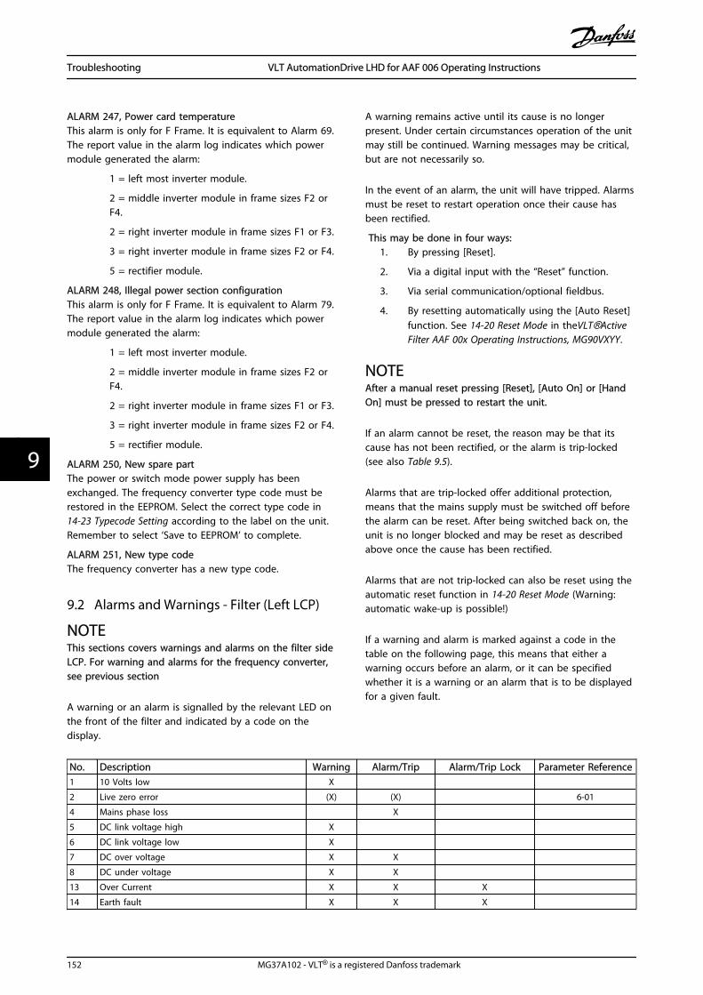
ALARM 247, Power card temperatureThis alarm is only for F Frame. It is equivalent to Alarm 69.The report value in the alarm log indicates which powermodule generated the alarm:
1 = left most inverter module.
2 = middle inverter module in frame sizes F2 orF4.
2 = right inverter module in frame sizes F1 or F3.
3 = right inverter module in frame sizes F2 or F4.
5 = rectifier module.
ALARM 248, Illegal power section configurationThis alarm is only for F Frame. It is equivalent to Alarm 79.The report value in the alarm log indicates which powermodule generated the alarm:
1 = left most inverter module.
2 = middle inverter module in frame sizes F2 orF4.
2 = right inverter module in frame sizes F1 or F3.
3 = right inverter module in frame sizes F2 or F4.
5 = rectifier module.
ALARM 250, New spare partThe power or switch mode power supply has beenexchanged. The frequency converter type code must berestored in the EEPROM. Select the correct type code in14-23 Typecode Setting according to the label on the unit.Remember to select ‘Save to EEPROM’ to complete.
ALARM 251, New type codeThe frequency converter has a new type code.
9.2 Alarms and Warnings - Filter (Left LCP)
NOTEThis sections covers warnings and alarms on the filter sideLCP. For warning and alarms for the frequency converter,see previous section
A warning or an alarm is signalled by the relevant LED onthe front of the filter and indicated by a code on thedisplay.
A warning remains active until its cause is no longerpresent. Under certain circumstances operation of the unitmay still be continued. Warning messages may be critical,but are not necessarily so.
In the event of an alarm, the unit will have tripped. Alarmsmust be reset to restart operation once their cause hasbeen rectified.
This may be done in four ways:1. By pressing [Reset].
2. Via a digital input with the “Reset” function.
3. Via serial communication/optional fieldbus.
4. By resetting automatically using the [Auto Reset]function. See 14-20 Reset Mode in theVLT®ActiveFilter AAF 00x Operating Instructions, MG90VXYY.
NOTEAfter a manual reset pressing [Reset], [Auto On] or [HandOn] must be pressed to restart the unit.
If an alarm cannot be reset, the reason may be that itscause has not been rectified, or the alarm is trip-locked(see also Table 9.5).
Alarms that are trip-locked offer additional protection,means that the mains supply must be switched off beforethe alarm can be reset. After being switched back on, theunit is no longer blocked and may be reset as describedabove once the cause has been rectified.
Alarms that are not trip-locked can also be reset using theautomatic reset function in 14-20 Reset Mode (Warning:automatic wake-up is possible!)
If a warning and alarm is marked against a code in thetable on the following page, this means that either awarning occurs before an alarm, or it can be specifiedwhether it is a warning or an alarm that is to be displayedfor a given fault.
No. Description Warning Alarm/Trip Alarm/Trip Lock Parameter Reference1 10 Volts low X
2 Live zero error (X) (X) 6-01
4 Mains phase loss X
5 DC link voltage high X
6 DC link voltage low X
7 DC over voltage X X
8 DC under voltage X X
13 Over Current X X X
14 Earth fault X X X
Troubleshooting VLT AutomationDrive LHD for AAF 006 Operating Instructions
152 MG37A102 - VLT® is a registered Danfoss trademark
99

No. Description Warning Alarm/Trip Alarm/Trip Lock Parameter Reference15 Hardware mismatch X X
16 Short Circuit X X
17 Control word timeout (X) (X) 8-04
23 Internal Fan Fault X
24 External Fan Fault X 14-53
29 Heatsink temp X X X
33 Inrush fault X X
34 Fieldbus fault X X
35 Option fault X X
38 Internal fault
39 Heatsink sensor X X
40 Overload of Digital Output Terminal 27 (X) 5-00, 5-01
41 Overload of Digital Output Terminal 29 (X) 5-00, 5-02
42 Overload of Digital Output On X30/6 (X) 5-32
42 Overload of Digital Output On X30/7 (X) 5-33
46 Pwr. card supply X X
47 24 V supply low X X X
48 1.8 V supply low X X
65 Control Board Over-temperature X X X
66 Heat sink Temperature Low X
67 Option Configuration has Changed X
68 Safe Stop Activated X1)
69 Pwr. Card Temp X X
70 Illegal FC configuration X
72 Dangerous Failure X1)
73 Safe Stop Auto Restart
76 Power Unit Setup X
79 Illegal PS config X X
80 Drive Initialised to Default Value X
244 Heatsink temp X X X
245 Heatsink sensor X X
246 Pwr.card supply X X
247 Pwr.card temp X X
248 Illegal PS config X X
250 New spare part X
251 New Type Code X X
300 Mains Cont. fault X
301 SC Cont. Fault X
302 Cap. Over Current X X
303 Cap. Earth Fault X X
304 DC Over Current X X
305 Mains Freq. Limit X
306 Compensation Limit X
308 Resistor temp X X
309 Mains Earth Fault X X
311 Switch. Freq. Limit X
312 CT Range X
314 Auto CT Interrupt X
315 Auto CT Error X
316 CT Location Error X
317 CT Polarity Error X
Troubleshooting VLT AutomationDrive LHD for AAF 006 Operating Instructions
MG37A102 - VLT® is a registered Danfoss trademark 153
9 9

No. Description Warning Alarm/Trip Alarm/Trip Lock Parameter Reference318 CT Ratio Error X
Table 9.5 Alarm/Warning code list
A trip is the action when an alarm has appeared. The tripwill coast the motor and can be reset by pressing [Reset]or make a reset by a digital input (Par. 5-1* [1]). The originevent that caused an alarm cannot damage the frequencyconverter or cause dangerous conditions. A trip lock is anaction when an alarm occurs, which may cause damage tofrequency converter or connected parts. A Trip Locksituation can only be reset by a power cycling.
LED indication
Warning yellow
Alarm flashing red
Trip locked yellow and red
Table 9.6
Alarm Word and Extended Status Word
Bit Hex Dec Alarm Word Warning Word Extended Status Word
0 00000001 1 Mains Cont. Fault Reserved Reserved
1 00000002 2 Heatsink Temp Heatsink Temp Auto CT Running
2 00000004 4 Earth Fault Earth Fault Reserved
3 00000008 8 Ctrl.Card Temp Ctrl.Card Temp Reserved
4 00000010 16 Ctrl. Word TO Ctrl. Word TO Reserved
5 00000020 32 Over Current Over Current Reserved
6 00000040 64 SC Cont. Fault Reserved Reserved
7 00000080 128 Cap. Over Current Cap. Over Current Reserved
8 00000100 256 Cap. Earth Fault Cap. Earth Fault Reserved
9 00000200 512 Inverter Overld. Inverter Overld. Reserved
10 00000400 1024 DC under Volt DC under Volt Reserved
11 00000800 2048 DC over Volt DC over Volt Reserved
12 00001000 4096 Short Circuit DC Voltage Low Reserved
13 00002000 8192 Inrush Fault DC Voltage High Reserved
14 00004000 16384 Mains ph. Loss Mains ph. Loss Reserved
15 00008000 32768 Auto CT Error Reserved Reserved
16 00010000 65536 Reserved Reserved Reserved
17 00020000 131072 Internal Fault 10V Low Password Time Lock
18 00040000 262144 DC Over Current DC Over Current Password Protection
19 00080000 524288 Resistor temp Resistor temp Reserved
20 00100000 1048576 Mains Earth Fault Mains Earth Fault Reserved
21 00200000 2097152 Switch. Freq. Limit Reserved Reserved
22 00400000 4194304 Fieldbus Fault Fieldbus Fault Reserved
23 00800000 8388608 24 V Supply Low 24V Supply Low Reserved
24 01000000 16777216 CT Range Reserved Reserved
25 02000000 33554432 1.8V Supply Low Reserved Reserved
26 04000000 67108864 Reserved Low Temp Reserved
27 08000000 134217728 Auto CT Interrupt Reserved Reserved
28 10000000 268435456 Option Change Reserved Reserved
29 20000000 536870912 Unit Initialized Unit Initialized Reserved
30 40000000 1073741824 Safe Stop Safe Stop Reserved
31 80000000 2147483648 Mains Freq. Limit Extended Status Word Reserved
Table 9.7 Description of Alarm Word, Warning Word and Extended Status Word
The alarm words, warning words and extended statuswords can be read out via serial bus or optional fieldbusfor diagnosis. See also 16-90 Alarm Word, 16-92 WarningWord and 16-94 Ext. Status Word. “Reserved” means that
the bit is not guaranteed to be any particular value.Reserved bits should not be used for any purpose.
Troubleshooting VLT AutomationDrive LHD for AAF 006 Operating Instructions
154 MG37A102 - VLT® is a registered Danfoss trademark
99

9.2.1 Fault Messages - Active Filter
WARNING 1, 10 volts lowThe control card voltage is below 10 V from terminal 50.Remove some of the load from terminal 50, as the 10 Vsupply is overloaded. Max. 15 mA or minimum 590 Ω.
WARNING/ALARM 2, Live zero errorThe signal on terminal 53 or 54 is less than 50% of thevalue set in parameters 6-10, 6-12, 6-20 or 6-22 respec-tively.
WARNING/ALARM 4, Mains phase lossA phase is missing on the supply side, or the mainsvoltage imbalance is too high.
WARNING 5, DC link voltage highThe intermediate circuit voltage (DC) is higher than thehigh voltage warning limit. The unit is still active.
WARNING 6, DC link voltage lowThe intermediate circuit voltage (DC) is below the under-voltage limit of the control system. The unit is still active.
WARNING/ALARM 7, DC overvoltageIf the intermediate circuit voltage exceeds the limit, theunit trips.
WARNING/ALARM 8, DC under voltageIf the intermediate circuit voltage (DC) drops below theunder voltage limit, the filter checks if a 24 V backupsupply is connected. If not, the unit trips. Check that themains voltage matches the nameplate specification.
WARNING/ALARM 13, Over Currentthe unit current limit has been exceeded.
ALARM 14, Earth (ground) faultThe sum current of the IGBT CTs does not equal zero.Check if the resistance of any phase to ground has a lowvalue. Make sure to check both before and after mainscontactor. Also make sure IGBT current transducers,connection cables, and connectors are ok.
ALARM 15, Incomp. HardwareA mounted option is not handled by the present ControlCard SW/HW.
ALARM 16, Short circuitThere is a short-circuit in the output. Turn off the unit andcorrect the error.
WARNING/ALARM 17, Control word timeoutThere is no communication to the unit.The warning will only be active when 8-04 Control WordTimeout Function is NOT set to OFF.Possible correction: Increase 8-03 Control Word TimeoutTime. Change 8-04 Control Word Timeout Function
WARNING 23, Internal fan faultInternal fans have failed due to defect hardware or fansnot mounted.
WARNING 24, External fan faultExternal fans have failed due to defect hardware or fansnot mounted.
ALARM 29, Heatsink tempThe maximum temperature of the heatsink has beenexceeded. The temperature fault will not be reset until thetemperature falls below a defined heatsink temperature.
ALARM 33, Inrush faultCheck whether a 24 V external DC supply has beenconnected.
WARNING/ALARM 34, Fieldbus communication faultThe fieldbus on the communication option card is notworking.
WARNING/ALARM 35, Option Fault:Contact your Danfoss supplier.
ALARM 38, Internal faultContact your Danfoss supplier.
ALARM 39, Heatsink sensorNo feedback from the heatsink temperature sensor.
WARNING 40, Overload of Digital Output Terminal 27Check the load connected to terminal 27 or remove short-circuit connection.
WARNING 41, Overload of Digital Output Terminal 29Check the load connected to terminal 29 or remove short-circuit connection.
WARNING 42, Overload of Digital Output on X30/6 orOverload of Digital Output on X30/7For X30/6, check the load connected to X30/6 or removeshort-circuit connection.
For X30/7, check the load connected to X30/7 or removeshort-circuit connection.
WARNING 43, Ext. Supply (option)The external 24 V DC supply voltage on the option is notvalid.
ALARM 46, Power card supplyThe supply on the power card is out of range.
WARNING 47, 24 V supply lowContact your Danfoss supplier.
WARNING 48, 1.8 V supply lowContact your Danfoss supplier.
WARNING/ALARM/TRIP 65, Control card over temperatureControl card over temperature: The cutout temperature ofthe control card is 80° C.
WARNING 66, Heatsink temperature lowThis warning is based on the temperature sensor in theIGBT module.
Troubleshooting:
The heatsink temperature measured as 0° C could indicatethat the temperature sensor is defective causing the fanspeed to increase to the maximum. If the sensor wirebetween the IGBT and the gate drive card is disconnected,this warning would result. Also, check the IGBT thermalsensor.
Troubleshooting VLT AutomationDrive LHD for AAF 006 Operating Instructions
MG37A102 - VLT® is a registered Danfoss trademark 155
9 9

ALARM 67, Option module configuration has changedOne or more options have either been added or removedsince the last power-down.
ALARM 68, Safe stop activatedSafe stop has been activated. To resume normal operation,apply 24 V DC to terminal 37, then send a reset signal (viaBus, Digital I/O, or by pressing [Reset]. See 5-19 Terminal 37Safe Stop.
ALARM 69, Power card temperatureThe temperature sensor on the power card is either toohot or too cold.
ALARM 70, Illegal FC ConfigurationActual combination of control board and power board isillegal.
WARNING 73, Safe stop auto restartSafe stopped. Note that with automatic restart enabled,the motor may start when the fault is cleared.
WARNING 77, Reduced power mode:This warning indicates that the frequency converter isoperating in reduced power mode (i.e. less than theallowed number of inverter sections). This warning will begenerated on power cycle when the frequency converter isset to run with fewer inverters and will remain on.
ALARM 79, Illegal power section configurationThe scaling card is the incorrect part number or notinstalled. Also MK102 connector on the power card couldnot be installed.
ALARM 80, Unit initialized to default valueParameter settings are initialized to default settings after amanual reset.
ALARM 244, Heatsink temperatureReport value indicates source of alarm (from left):1-4 Inverter5-8 Rectifier
ALARM 245, Heatsink sensorNo feedback from the heatsink sensor. Report valueindicates source of alarm (from left):1-4 Inverter5-8 Rectifier
ALARM 246, Power card supplyThe supply on the power card is out of range Report valueindicates source of alarm (from left):1-4 Inverter5-8 Rectifier
ALARM 247, Power card temperaturePower card over temperature Report value indicates sourceof alarm (from left):1-4 Inverter5-8 Rectifier
ALARM 248, Illegal power section configurationPower size configuration fault on the power card Reportvalue indicates source of alarm (from left):1-4 Inverter
5-8 Rectifier
ALARM 249, Rect. low temp.The temperature of the rectifier heat sink is too low. Thiscould indicate that the temperature sensor is defect.
ALARM 250, New spare partThe power or switch mode power supply has beenexchanged. The filter type code must be restored in theEEPROM. Select the correct type code in 14-23 TypecodeSetting according to the label on the unit. Remember toselect ‘Save to EEPROM’ to complete.
ALARM 251, New type codeThe filter has a new type code.
ALARM 300, Mains Cont. FaultThe feedback from the mains contactor did not match theexpected value within the allowed time frame. Contactyour Danfoss supplier.
ALARM 301, SC Cont. FaultThe feedback from the soft charge contactor did notmatch the expected value within the allowed time frame.Contact your Danfoss supplier.
ALARM 302, Cap. Over CurrentExcessive current was detected through the AC capacitors.Contact your Danfoss supplier.
ALARM 303, Cap. Earth FaultAn earth fault was detected through the AC capacitorcurrents. Contact your Danfoss supplier.
ALARM 304, DC Over CurrentExcessive current through the DC link capacitor bank wasdetected. Contact your Danfoss supplier.
ALARM 305, Mains Freq. LimitThe mains frequency was outside the limits. Verify that themains frequency is within product specification.
ALARM 306, Compensation LimitThe needed compensation current exceeds unit capability.Unit is running at full compensation.
ALARM 308, Resistor tempExcessive resistor heatsink temperature detected.
ALARM 309, Mains Earth FaultAn earth fault was detected in the mains currents. Checkthe mains for shorts and leakage current.
ALARM 310, RTDC Buffer FullContact your Danfoss supplier.
ALARM 311, Switch. Freq. LimitThe average switching frequency of the unit exceeded thelimit. Verify that 300-10 Active Filter Nominal Voltage and300-22 CT Nominal Voltage are set correctly. If so, contactyour Danfoss supplier.
ALARM 312, CT RangeCurrent transformer measurement limitation was detected.Verify that the CTs used are an appropriate ratio.
ALARM 314, Auto CT InterruptAuto CT detection was interrupted by the user.
Troubleshooting VLT AutomationDrive LHD for AAF 006 Operating Instructions
156 MG37A102 - VLT® is a registered Danfoss trademark
99

ALARM 315, Auto CT ErrorAn error was detected while performing auto CT detection.Contact your Danfoss supplier.
ALARM 316, CT Location ErrorThe Auto CT function could not determine the correctlocations of the CTs.
ALARM 317, CT Polarity ErrorThe Auto CT function could not determine the correctpolarity of the CTs.
ALARM 318, CT Ratio ErrorThe Auto CT function could not determine the correctprimary rating of the CTs.
Troubleshooting VLT AutomationDrive LHD for AAF 006 Operating Instructions
MG37A102 - VLT® is a registered Danfoss trademark 157
9 9
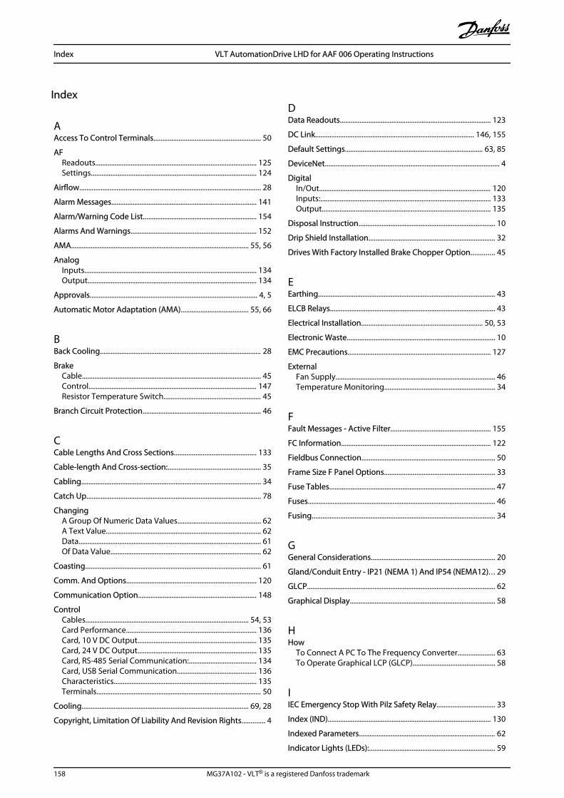
Index
AAccess To Control Terminals............................................................ 50
AFReadouts........................................................................................... 125Settings............................................................................................. 124
Airflow...................................................................................................... 28
Alarm Messages.................................................................................. 141
Alarm/Warning Code List................................................................ 154
Alarms And Warnings....................................................................... 152
AMA.................................................................................................... 55, 56
AnalogInputs................................................................................................. 134Output............................................................................................... 134
Approvals.............................................................................................. 4, 5
Automatic Motor Adaptation (AMA)...................................... 55, 66
BBack Cooling........................................................................................... 28
BrakeCable..................................................................................................... 45Control............................................................................................... 147Resistor Temperature Switch....................................................... 45
Branch Circuit Protection................................................................... 46
CCable Lengths And Cross Sections.............................................. 133
Cable-length And Cross-section:.................................................... 35
Cabling..................................................................................................... 34
Catch Up.................................................................................................. 78
ChangingA Group Of Numeric Data Values............................................... 62A Text Value....................................................................................... 62Data....................................................................................................... 61Of Data Value..................................................................................... 62
Coasting................................................................................................... 61
Comm. And Options......................................................................... 120
Communication Option................................................................... 148
ControlCables............................................................................................ 54, 53Card Performance......................................................................... 136Card, 10 V DC Output................................................................... 135Card, 24 V DC Output................................................................... 135Card, RS-485 Serial Communication:...................................... 134Card, USB Serial Communication............................................. 136Characteristics................................................................................ 135Terminals............................................................................................. 50
Cooling.............................................................................................. 69, 28
Copyright, Limitation Of Liability And Revision Rights............. 4
DData Readouts..................................................................................... 123
DC Link......................................................................................... 146, 155
Default Settings.............................................................................. 63, 85
DeviceNet.................................................................................................. 4
DigitalIn/Out................................................................................................. 120Inputs:................................................................................................ 133Output............................................................................................... 135
Disposal Instruction............................................................................. 10
Drip Shield Installation....................................................................... 32
Drives With Factory Installed Brake Chopper Option............. 45
EEarthing.................................................................................................... 43
ELCB Relays............................................................................................. 43
Electrical Installation.................................................................... 50, 53
Electronic Waste................................................................................... 10
EMC Precautions................................................................................ 127
ExternalFan Supply.......................................................................................... 46Temperature Monitoring.............................................................. 34
FFault Messages - Active Filter........................................................ 155
FC Information.................................................................................... 122
Fieldbus Connection........................................................................... 50
Frame Size F Panel Options.............................................................. 33
Fuse Tables............................................................................................. 47
Fuses.......................................................................................................... 46
Fusing....................................................................................................... 34
GGeneral Considerations...................................................................... 20
Gland/Conduit Entry - IP21 (NEMA 1) And IP54 (NEMA12).. . 29
GLCP.......................................................................................................... 62
Graphical Display.................................................................................. 58
HHow
To Connect A PC To The Frequency Converter..................... 63To Operate Graphical LCP (GLCP).............................................. 58
IIEC Emergency Stop With Pilz Safety Relay................................. 33
Index (IND)............................................................................................ 130
Indexed Parameters............................................................................. 62
Indicator Lights (LEDs):....................................................................... 59
Index VLT AutomationDrive LHD for AAF 006 Operating Instructions
158 MG37A102 - VLT® is a registered Danfoss trademark
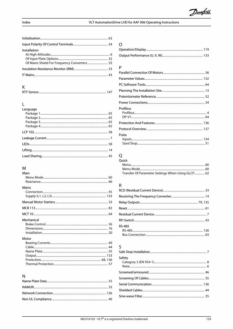
Initialisation............................................................................................ 63
Input Polarity Of Control Terminals............................................... 54
InstallationAt High Altitudes................................................................................ 6Of Input Plate Options................................................................... 32Of Mains Shield For Frequency Converters............................ 33
Insulation Resistance Monitor (IRM).............................................. 33
IT Mains.................................................................................................... 43
KKTY Sensor............................................................................................ 147
LLanguage
Package 1............................................................................................ 65Package 2............................................................................................ 65Package 3............................................................................................ 65Package 4............................................................................................ 65
LCP 102..................................................................................................... 58
Leakage Current...................................................................................... 7
LEDs........................................................................................................... 58
Lifting........................................................................................................ 14
Load Sharing.......................................................................................... 45
MMain
Menu Mode........................................................................................ 60Reactance........................................................................................... 66
MainsConnection......................................................................................... 45Supply (L1, L2, L3).......................................................................... 133
Manual Motor Starters........................................................................ 33
MCB 113................................................................................................... 82
MCT 10...................................................................................................... 64
MechanicalBrake Control..................................................................................... 56Dimensions........................................................................................ 16Installation.......................................................................................... 20
MotorBearing Currents.............................................................................. 49Cable..................................................................................................... 44Name Plate......................................................................................... 55Output............................................................................................... 133Protection.................................................................................. 68, 136Thermal Protection.......................................................................... 57
NName Plate Data................................................................................... 55
NAMUR..................................................................................................... 33
Network Connection......................................................................... 126
Non UL Compliance............................................................................. 46
OOperation/Display............................................................................. 119
Output Performance (U, V, W)....................................................... 133
PParallel Connection Of Motors......................................................... 56
Parameter Values............................................................................... 132
PC Software Tools................................................................................. 64
Planning The Installation Site.......................................................... 13
Potentiometer Reference.................................................................. 52
Power Connections.............................................................................. 34
ProfibusProfibus.................................................................................................. 4DP-V1.................................................................................................... 64
Protection And Features.................................................................. 136
Protocol Overview............................................................................. 127
PulseInputs................................................................................................. 134Start/Stop............................................................................................ 51
QQuick
Menu..................................................................................................... 60Menu Mode........................................................................................ 60Transfer Of Parameter Settings When Using GLCP.............. 62
RRCD (Residual Current Device)........................................................ 33
Receiving The Frequency Converter............................................. 14
Relay Outputs............................................................................... 79, 135
Reset.......................................................................................................... 61
Residual Current Device....................................................................... 7
RFI Switch................................................................................................ 43
RS-485RS-485................................................................................................ 126Bus Connection................................................................................. 63
SSafe Stop Installation............................................................................. 7
SafetyCategory 3 (EN 954-1)....................................................................... 8Note......................................................................................................... 6
Screened/armoured............................................................................ 46
Screening Of Cables:........................................................................... 35
Serial Communication...................................................................... 136
Shielded Cables..................................................................................... 44
Sine-wave Filter..................................................................................... 35
Index VLT AutomationDrive LHD for AAF 006 Operating Instructions
MG37A102 - VLT® is a registered Danfoss trademark 159

SpaceSpace.................................................................................................... 20Heaters And Thermostat............................................................... 33
Special Functions............................................................................... 121
Speed Up/Down................................................................................... 52
Start/Stop................................................................................................ 51
Stator Leakage Reactance................................................................. 66
StatusStatus.................................................................................................... 60Messages............................................................................................. 58
Step-by-Step.......................................................................................... 62
Stopping Category 0 (EN 60204-1)................................................... 8
Surroundings....................................................................................... 136
Switches S201, S202, And S801....................................................... 54
Switching Frequency:......................................................................... 35
Symbols...................................................................................................... 5
TTelegram Length (LGE).................................................................... 128
Terminal Locations - Frame Size D13............................................ 22
Thermistor............................................................................................... 68
TorqueTorque.................................................................................................. 43Characteristics................................................................................ 133For Terminals..................................................................................... 44
UUnpacking............................................................................................... 14
VVoltage
Level................................................................................................... 133Reference Via A Potentiometer................................................... 52
WWarning Against Unintended Start.................................................. 6
Warnings............................................................................................... 141
Wire Access............................................................................................. 21
Index VLT AutomationDrive LHD for AAF 006 Operating Instructions
160 MG37A102 - VLT® is a registered Danfoss trademark

www.danfoss.com/drives
*MG37A102*130R0401 MG37A102 Rev. 2012-03-01
