making an automated control system robocopaos.ro/wp-content/anale/tvol7nr1art.8.pdf · making an...
TRANSCRIPT

Annals of the Academy of Romanian Scientists
Online Edition Series on Engineering Sciences
ISSN 2066 – 8570 Volume 7, Number 1/2015 81
MAKING AN AUTOMATED CONTROL SYSTEM ROBOCOP
Ion CHIUŢĂ1, Gabriel Alexandru PETICĂ
2, Cătălina Cristina PETICĂ
3,
Alexandru Ionuţ CHIUŢĂ4
Rezumat. Am ales această lucrare, deoarece considerăm că în viitor totul va fi
automatizat pentru a uşura munca noastră. Aceasta lucrare se poate adresa în mod
special armatei, dar nu numai. În stadiul la care se găseşte, în prezent, robotul poate
căra greutăţi, dintr-un loc în altul. Desigur că se pot monta pe el diverse alte device-uri
(braţe), pentru a efectua şi alte operaţii, cum ar fi: vopsire, manipulare obiecte şi
dispozitive pirotehnice. Este o jucărie periculoasă, de aceea el se manevrează foarte
uşor, fiind foarte, foarte sensibil la comenzi. În prezent, eu împreună cu tatăl meu lucrăm
la un alt robot, mai puternic cu motor termic, cutie de viteze în 5 trepte automată, toate
roţile viratoare şi tracţiune 4x4.
Abstract. We have chosen this work because we believe that in the future everything will
be automated to facilitate the people’s work. This work can specifically address to the
military, but not only. In the current stage, the robot can carry weights from one place to
another. Of course, various other devices or arms can be mounted on it to perform other
tasks as well, such as painting, handling objects and pyrotechnic devices. It is a
dangerous toy, very easy to handle and very sensitive to operate. Currently, my father
and I work to another robot, more powerful, with combustion engine, 5-speed automatic
gearbox, all steering wheels and traction on all wheels.
Keywords: automation systems, robot, pyrotechnic devices, combustion engine
1. Chasses
The chassis was made of rectangular pipes of
15 mm × 15 mm × 3 mm [figure 1]. We chose this
rectangular pipe shape because it is light and easy to
maintain against the external agents, such as corrosion
(the enemy of all metals). The first step we did, it was
drawing a pattern and then we did start working on the
rectangular pipe. The entire frame has connections made
at 45° and the welds were carried out in argon gas.
Figure 1: rectangular pipes
1Prof. dr. ing., Preşedintele Secţiei de Ştiinţe Tehnice a AOSR.
2ing., Universitatea „Politehnica” din Bucureşti.
3drd. ing., Universitatea „Politehnica” din Bucureşti, Academia Oamenilor de Ştiinţă din România
4ş.l. dr. ing., Universitatea „Politehnica” din Bucureşti.

Ion Chiuţă, Gabriel Alexandru Petică, Cătălina Cristina Petică,
82 Alexandru Ionuţ Chiuţă, Mihai Şerban Sindile
The image below is the chassis [figure 2a)]. In the next step, we installed the
traction, which includes the engine, sprockets, chain, differential subassembly,
planetary shaft and bearings [figure 2b)]
Figure 2a) chassis Figure 2b) the traction
In the following we present the elements of which we have spoken above. Like
any machine, the main element is the engine. What is the engine? This is a
question that we all ask ourselves. The engine receives electricity and converts
into mechanical energy. This is the electric motor.
2. A little history about the DC motor
The DC motor was invented in 1873 by Zénobe Gramme by connecting a
DC generator to a like generator. Thus, it was observed that the machine rotates,
making conversion of electric energy absorbed from the generator. The DC motor
has on the stator the magnetic poles and concentrated polar coils which create the
excitation magnetic field. On the engine shaft a manifold is located which changes
the direction of current flow through the rotor winding, so that the magnetic field
excitation exerts continuously a force to the rotor.
Components of a motor:
1. motor shaft
2. stator
3. clamping screw
4. brushes holder
5. collector
6. carbon brushes
Figure 3: components of a motor
Making an automated control system Robocop 83
The current conductors of the rotor winding will have one or more pairs of
equivalent magnetic poles. The rotor moves in the excitation magnetic field until
the rotor poles align themselves right opposite to the stator poles. In the same
time, the collector changes the direction of the rotor current so that the polarity of
the rotor reverses and the rotor will continue moving to the next alignment of the
magnetic poles. The motor speed is proportional with the applied voltage to the
rotor winding and inversely with excitation magnetic field. The speed is adjusted
by varying the voltage applied to the motor up to the rated voltage. Higher speeds
are obtained by weakening the magnetic excitation field. Both methods target a
variable voltage that can be obtained using a DC generator, connecting a set of
resistors in the circuit or using the power electronics.
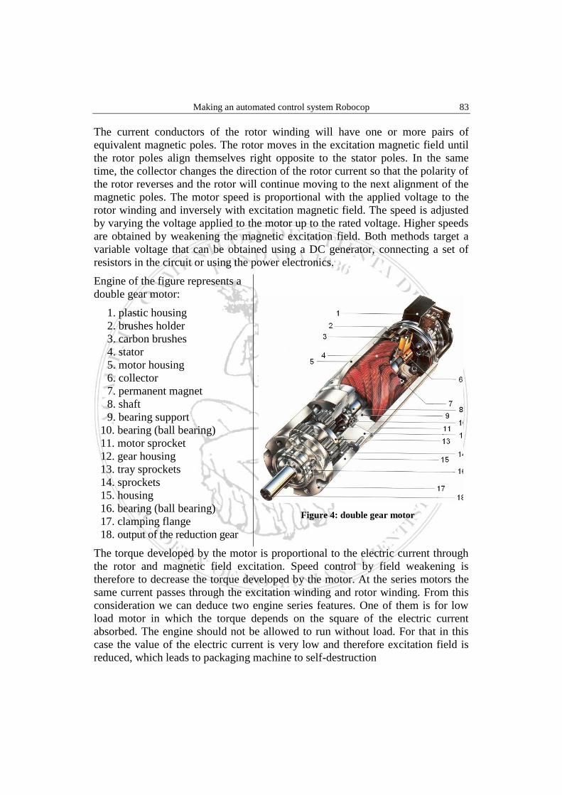
Engine of the figure represents a
double gear motor:
1. plastic housing
2. brushes holder
3. carbon brushes
4. stator
5. motor housing
6. collector
7. permanent magnet
8. shaft
9. bearing support
10. bearing (ball bearing)
11. motor sprocket
12. gear housing
13. tray sprockets
14. sprockets
15. housing
16. bearing (ball bearing)
17. clamping flange
18. output of the reduction gear
Figure 4: double gear motor
The torque developed by the motor is proportional to the electric current through
the rotor and magnetic field excitation. Speed control by field weakening is
therefore to decrease the torque developed by the motor. At the series motors the
same current passes through the excitation winding and rotor winding. From this
consideration we can deduce two engine series features. One of them is for low
load motor in which the torque depends on the square of the electric current
absorbed. The engine should not be allowed to run without load. For that in this
case the value of the electric current is very low and therefore excitation field is
reduced, which leads to packaging machine to self-destruction
Ion Chiuţă, Gabriel Alexandru Petică, Cătălina Cristina Petică,
84 Alexandru Ionuţ Chiuţă, Mihai Şerban Sindile
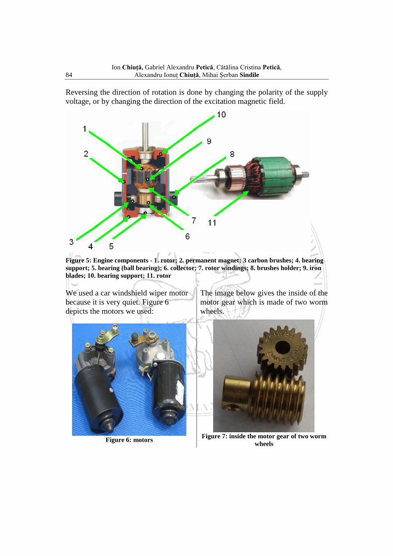
Reversing the direction of rotation is done by changing the polarity of the supply
voltage, or by changing the direction of the excitation magnetic field.
Figure 5: Engine components - 1. rotor; 2. permanent magnet; 3 carbon brushes; 4. bearing
support; 5. bearing (ball bearing); 6. collector; 7. rotor windings; 8. brushes holder; 9. iron
blades; 10. bearing support; 11. rotor
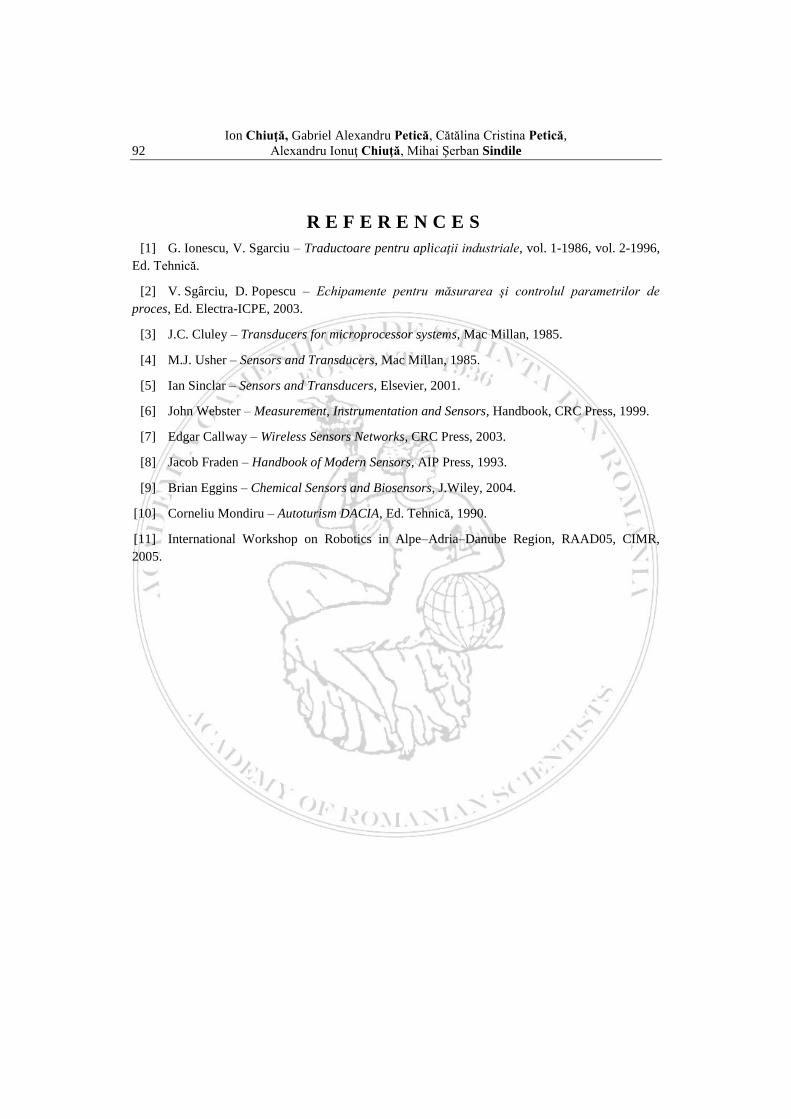
We used a car windshield wiper motor
because it is very quiet. Figure 6
depicts the motors we used:
The image below gives the inside of the
motor gear which is made of two worm
wheels.
Figure 6: motors
Figure 7: inside the motor gear of two worm
wheels

Making an automated control system Robocop 85
3. Sprockets and transmission chain
Traction is on the rear wheels and therefore the system
is provided with bigger wheels. The connection between
the motor and the planetary shaft is carried out by a
transmission chain and two sprockets. The driving wheel
is larger than the driven wheel and therefore it was
mounted on the motor shaft to earn a higher speed at the
wheels.
Figure 8: driving wheel
The driven wheel, being smaller, was mounted on a differential which is designed
to change the speed depending on the steering wheel. Another component which
belongs to the transmission is the differential. It allows the rotation at different
levels per minute of the left and right wheels. At curves, outer wheel is spinning
faster than the inner one to compensate the greater distance it needs to travel. The
picture below shows the differential subassembly:
A. differential housing
B. output shaft
C. worm gear
D. worm sprocket
E. synchronization sprockets
F. hypoid wheel (from engine)
G. output shaft
Figure 9: differential subassembly
The link between the two sprockets are
made using a transmission chain.
(Figure 10)
Figure 10: transmission chain

Ion Chiuţă, Gabriel Alexandru Petică, Cătălina Cristina Petică,
86 Alexandru Ionuţ Chiuţă, Mihai Şerban Sindile
4. Direction
Direction is another important element. The maximum slope is 15° and it was
made from a motor supplied with 6 V, the steering rods being adjustable.
Figure 11: the steering box
We chose to act directly by electric motor (servo motor), because it can be
controlled much smoother than other ordinary motor. Something that helps me a
lot is a position transducer, which it always indicates the angle at which the
wheels are tilted.
5. General structure of a transducer
“Sensor” is very popular in the US region, while the notion of “transducer” – is
commonly used in the European area. The word "sensor" is derived from the Latin
–“sentire”- meaning "to perceive", while the "transducer" in translation means
"to cross". A dictionary definition assigns the word "sensor" means "device that
detects a change in a physical stimulus and converts it into a signal that can be
measured or recorded", while the word "transducer" is the definition of "device
transferring power from one system to another in the same form or in a different
one". Sensitive boundary between the two notions: one can use the word "sensor"
for the sensing element itself and the word 'transducer' for the sensing element and
associated circuitry. Example: we may say that a thermistor is a "sensor", while a
thermistor plus a measuring resistive bridge (which converts the electrical
resistance variations in the voltage variations) is a "transducer". In this sense, all
transducers will contain a sensor but most of the sensors (but not all!) will be
transducers. In a general framework, a transducer is a device that converts a signal
of a certain physical nature in a corresponding signal having a different physical
nature. A transducer basically is a power converter in which the input always has
energy or power. However, the power (which by integration gives energy)
associated with the input signal must be large enough not to be disturbed by the
measuring transducer size. Or, the transducer must influence through its input
circuit negligibly the size measured (it says that the power taken from the size
measured should be below a certain value called the available power). Example:
measurement of a force using a strain gauge. Since there are six different classes
of signals - mechanical, thermal, magnetic, electrical, optical and chemical - we
can say that any device that converts signals from one class to another is
considered to be a transducer.

Making an automated control system Robocop 87
Mechanical
Mechanical
Termical Termical
INPUTS PROCESSING OUTPUTS
Magnetical Magnetical
Electrical Electrical
Optical TRANSDUCER Optical
Chemical Chemical
Figure 12: schematic transducer
Definition: transducer is a device that establishes correspondence between a
physical quantity (process parameter) varying in a certain defaulted range and a
calibrated electrical signal suitable to a measurement situation.
Figure 13: the transducer as component of the automated system
Considering the definition introduced at the beginning of the paragraph, there are
authors and even companies that use the concept of transducer for those elements
that convert primarily. The sensor is linked to the perception of measured values,
suggesting a similarity with human behavior in the manner of obtaining
information about physical quantities. Definition: sensor means assemblies of
sensing devices for determining a field of values for the physical quantity in a
similar manner to the human sensing organs.
6. Conclusion
The sensors allow obtaining images or maps of a scene through similar human
paths. This should be understood as a defined input, i.e. field values obtained by
T
X - INPUT
(tag)
Y - OUTPUT
(calibrated electrical
signal)
PROCESS
AUTOMATION
DEVICES
(Controllers, PC-s
etc.)

Ion Chiuţă, Gabriel Alexandru Petică, Cătălina Cristina Petică,
88 Alexandru Ionuţ Chiuţă, Mihai Şerban Sindile
sensors must be processed to more accurate picture in order to playback the
image. So, it has to have a similar representation to that formed in the human
thinking. In light of the definition, a sensor performs the same function as a
transducer, i.e. charge the state of a physical quantity which converts the electrical
signal.
Consequently, the functional structure of a sensor complies - in principle – with
the same pattern as a transducer. This explains why the two notions are frequently
used in explaining the functional principles for various constructions. However, at
least three characteristics define the sensors:
► miniaturization, which allows measurements of the investigated quantities;
► functional multiplication, meaning existing in the structure of a sensor of a
large number of sensitive devices fulfilling the same function, arranged in a linear
or matrix distribution;
► sensorial fusion, which involves the gathering of several sensors in a
unique configuration to provide the desired functionality;
► these features, together with the property of "imitation" of the human
senses, make the sensors to differentiate out of transducers. Illustration: the
phenomenon of piezoelectricity used in construction of the force transducers and
tactile sensors, as well;
► functional multiplication, specific to sensors, makes the local processing to
be different - even in principle – of those of transducers, something which leads to
a further differentiation of the two concepts.
We use differentially the two concepts considering the structural composition and
scope of the applications. Illustration: to control a robot arm one uses linear
displacement transducers (forward / reverse), rotation (left / right) and proximity
to sense the approach of a particular landmark. But also, a number of the sensors
such as visual sensors for recognition of the objects, effort (tactile) sensors for
clamping the parts, auditory sensors for recognizing the voice commands.
7. Place of the transducer in the automated systems
The two cases presented show:
● place of the sensor in the process automation as element located on the
information path;
● carry out its role of the measurement tasks;
Consequences:
● transducer has metrology features well established that guarantees the quality
measurement

Making an automated control system Robocop 89
● diversity of the process variables, that must be highlighted, lead to a variety
of the constructive principles used in the transducer input
● its output is restricted to electrical signals compatible to elements of
automation installation to which they are coupled.
Figure 14: position transducer used for “ROBOCOP”
8. Electronic subassembly
Electronic subassembly is the most complicated part of the robot. As the most
important component, we called the set of the several components working
"together", artificial brain. It includes a number of electronic assemblies each
designed to perform a specific function, such as:
- reception subassembly
- power supply
- sense exchangers
- high power inverters
- voltage stabilizers
Reception subassembly
The robot is controlled by a remote control and can reach a maximum distance up
to 4 km. The reception assembly is supplied with 4.8 V stabilized. The remote
control is proportional and allows a very smooth motor variation.
The receiver is fed to 4,8V generated by four rechargeable batteries of 1.2 V and
2700 mAh (NiMH) (see figure 15).
Being controlled at such a great distance, it was provided with a surveillance
camera wirelessly. All images are transmitted in real time.

Ion Chiuţă, Gabriel Alexandru Petică, Cătălina Cristina Petică,
90 Alexandru Ionuţ Chiuţă, Mihai Şerban Sindile
Figure 15: surveillance camera wirelessly and batteries group
Figure 16: schematic voltage stabilizer, which supplies the receiver
9. Power supply
All assemblies are supplied at different voltages, so voltage regulators have been
provided similarly to the above one, but working at different voltages. The entire
robot, fully mounted on the chassis, weighs about 20 kg.
All power supplies are generated by rechargeable batteries. The traction engine is
provided with 212 V/7 Ah (Pb) batteries and the steering engine has a battery of
6 V / 12 Ah (Pb). Two batteries of 12V/7Ah (Pb), shown below have been used to
supply the traction motor (figure 17).
Figure 17: batteries of 12V/7Ah (Pb) for the supply the traction motor

Making an automated control system Robocop 91
The battery is 6V/12Ah (Pb) and we used it to supply the power to the steering
motor.
Sense exchangers are needed to change the direction of the
motors. Large power exchangers increase or decrease the
motor speed. Figure 18 contains electronic components
printed circuit, a traction motor subassembly.
Figure 18: electronic components printed circuit
In this period, the robot has undergone a "radical" transformation: the maximum
steering angle was before 15° and now it is 45°. Modifications brought up:
- The machine has been "cut" into two parts, the whole front was removed;
- It was welded other profiles so that the robot allows a 45° angle;
We are working at another more refined robot, with thermal engine on gasoline.
This robot will be 44 (all driven wheels), all wheels will be turning wheels, 5-
speed automatic gearbox and reversing system.
Figure 19: Functional Assembly Robocop
Ion Chiuţă, Gabriel Alexandru Petică, Cătălina Cristina Petică,
92 Alexandru Ionuţ Chiuţă, Mihai Şerban Sindile
R E F E R E N C E S
[1] G. Ionescu, V. Sgarciu – Traductoare pentru aplicaţii industriale, vol. 1-1986, vol. 2-1996,
Ed. Tehnică.
[2] V. Sgârciu, D. Popescu – Echipamente pentru măsurarea şi controlul parametrilor de
proces, Ed. Electra-ICPE, 2003.
[3] J.C. Cluley – Transducers for microprocessor systems, Mac Millan, 1985.
[4] M.J. Usher – Sensors and Transducers, Mac Millan, 1985.
[5] Ian Sinclar – Sensors and Transducers, Elsevier, 2001.
[6] John Webster – Measurement, Instrumentation and Sensors, Handbook, CRC Press, 1999.
[7] Edgar Callway – Wireless Sensors Networks, CRC Press, 2003.
[8] Jacob Fraden – Handbook of Modern Sensors, AIP Press, 1993.
[9] Brian Eggins – Chemical Sensors and Biosensors, J.Wiley, 2004.
[10] Corneliu Mondiru – Autoturism DACIA, Ed. Tehnică, 1990.
[11] International Workshop on Robotics in Alpe–Adria–Danube Region, RAAD05, CIMR,
2005.