makani power, inc. - energykitesystems · makani power, inc. makani power is committed to working...
TRANSCRIPT

1
1 2 3
In operation, the wing flies in a circular path at an altitude of 400 m.
Before launch, and in unfavorable conditions, the wing is stowed at the top of the spar buoy.
The wing launches and lands by hovering like a helicopter.
Response to the Federal Aviation AuthorityDocket No.: FAA-2011-1279; Notice No. 11-07
Notification for Airborne Wind Energy Systems (AWES)
Makani Power, inC.Makani Power is committed to working with the FAA to create a safe and open NAS that allows for the operation of Airborne Wind Turbines (AWT). As a leader in the field of airborne wind energy, Makani is eager to begin collaborating with the FAA on regulation and safety procedures, further enabling the development of the AWT.
2.1 The Makani Power AWT
The AWT operates on many of the same principles as a conventional turbine blade but incorporates only the most effective part: the aerodynamically effective blade tips. In a conventional wind turbine, the last 25% of the blade is responsible for more than half of the energy production.
The Makani wing mimics the motion of these blade tips using only a fraction of the materi-als: there is no tower, hub, nacelle and only one blade. The wingspan of a Makani AWT is comparable in size to one blade of a similarly scaled traditional wind turbine.Power is generated by several turbines mounted on the wing. These turbines are small, lightweight and operate without gearboxes (direct drive) as they extract power from the high speed airflow moving across the wing.
The AWT is materials efficient: its wingspan is comparable in size to one blade of a similarly scaled turbine and there is no tower, hub, nacelle, or gearbox. The tensile based design of the Makani AWT further decreases mass by distributing aerodynamic forces across the wing with a bridle.
The Makani AWT is fully autonomous. Like an airplane, the path of the AWT is directed by flaps on the wing controlled by an onboard computer. The AWT has a proven ability to perform the modes of flight needed for complete autonomous operation. In field testing Makani has demonstrated: take-off, hover, transitioninto crosswind, crosswind power generation, transition out of crosswind, reeling in and perching.
Figure 1. Makani AWT flight modes.
2
2.2 The Advantages of the AWT
For the wind energy industry to flourish and to make low cost renewable energy a reality, three issues must be solved:
Consistency of generationMaterial efficiency Useable land
Makani’s AWT can overcome the limitations of conventional wind energy by reaching the stronger and steadier winds at altitude. In addition, the AWT achieves substantial improvements in low-wind performance because the entire span of the wing operates at the tip speed of a conventional turbine. This increases the power generation of each tur-bine and opens up more areas of economically viable wind resource. In the continental United States alone, AWTs can economically access over five times the land area available to conventional wind turbines. The AWT’s low mass means that it can also be sited far offshore in deep water, anchored by a floating platform.
2.3 The Makani Airframe
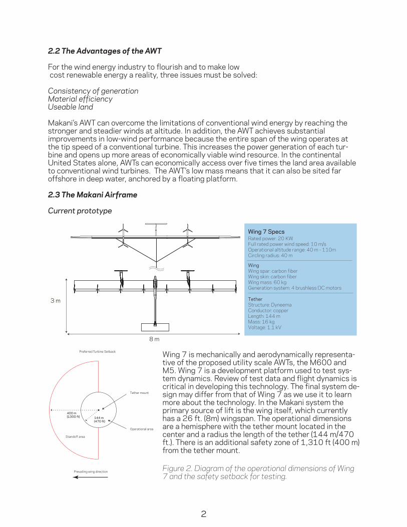
Current prototype
8 m
3 m
Wing 7 SpecsRated power: 20 KWFull rated power wind speed: 10 m/s
Wing mass: 60 kgGeneration system: 4 brushless DC motors
WingWing spar: carbon fiberWing skin: carbon fiber
Length: 144 m
Tether
Mass: 16 kg
Conductor: copperStructure: Dyneema
Voltage: 1.1 kV
Circling radius: 40 mOperational altitude range: 40 m - 110m
28 m
8 m
M600 SpecsRated power: 600 kWFull rated power wind speed: 9m/s
Wing mass: 1,050 kgGeneration system: 8 brushless DC motors
WingWing spar: carbon fiberWing skin: e-glass
Length: 440m
Tether
Mass: 250 kg
Conductor: aluminumStructure: pultruded carbon fiber
Voltage: 8 kV
Circling radius: 135 mOperational altitude range: 140m - 310m
65 m
15 m
M5 SpecsRated power: 5 MWFull rated power wind speed: 9 m/s
Wing mass: 9,900 kgGeneration system: 8 brushless DC motors
WingWing spar: carbon fiberWing skin: e-glass
Length: 1,060 m
Tether
Mass: 3,660 kg
Conductor: aluminumStructure: pultruded carbon fiber
Voltage: 8 kV
Circling radius: 265 mOperational altitude range: 350m - 650 m
Wing 7 is mechanically and aerodynamically representa-tive of the proposed utility scale AWTs, the M600 and M5. Wing 7 is a development platform used to test sys-tem dynamics. Review of test data and flight dynamics is critical in developing this technology. The final system de-sign may differ from that of Wing 7 as we use it to learn more about the technology. In the Makani system the primary source of lift is the wing itself, which currently has a 26 ft. (8m) wingspan. The operational dimensions are a hemisphere with the tether mount located in the center and a radius the length of the tether (144 m/470 ft.). There is an additional safety zone of 1,310 ft (400 m) from the tether mount.
400 m(1300 ft)
Tether mount
Prevailing wing direction
Operational area
Standoff area
144 m(470 ft)
Preferred Turbine Setback
Figure 2. Diagram of the operational dimensions of Wing 7 and the safety setback for testing.

3
Proposed Final Systems
The M600 is a 600 kW, utility scale device meant for onshore wind farm applications. The operational dimensions are a hemisphere with the tether mount located in the center and a radius the length of the tether (440 m/ 1,440 ft.). There is an additional safety zone of 5,000 ft. (1.5 km) from the tether mount.
The 5 MW, M5 is a utility scale device developed specifically for deep water offshore locations greater than 15 miles from shore. The operational dimensions are a hemisphere with the tether mount located in the center and a radius the length of the tether (1,060 m/3,480ft.). There is an additional safety zone of 5,000 ft. (1.5 km) from the tether mount.
8 m
3 m
Wing 7 SpecsRated power: 20 KWFull rated power wind speed: 10 m/s
Wing mass: 60 kgGeneration system: 4 brushless DC motors
WingWing spar: carbon fiberWing skin: carbon fiber
Length: 144 m
Tether
Mass: 16 kg
Conductor: copperStructure: Dyneema
Voltage: 1.1 kV
Circling radius: 40 mOperational altitude range: 40 m - 110m
28 m
8 m
M600 SpecsRated power: 600 kWFull rated power wind speed: 9m/s
Wing mass: 1,050 kgGeneration system: 8 brushless DC motors
WingWing spar: carbon fiberWing skin: e-glass
Length: 440m
Tether
Mass: 250 kg
Conductor: aluminumStructure: pultruded carbon fiber
Voltage: 8 kV
Circling radius: 135 mOperational altitude range: 140m - 310m
65 m
15 m
M5 SpecsRated power: 5 MWFull rated power wind speed: 9 m/s
Wing mass: 9,900 kgGeneration system: 8 brushless DC motors
WingWing spar: carbon fiberWing skin: e-glass
Length: 1,060 m
Tether
Mass: 3,660 kg
Conductor: aluminumStructure: pultruded carbon fiber
Voltage: 8 kV
Circling radius: 265 mOperational altitude range: 350m - 650 m
8 m
3 m
Wing 7 SpecsRated power: 20 KWFull rated power wind speed: 10 m/s
Wing mass: 60 kgGeneration system: 4 brushless DC motors
WingWing spar: carbon fiberWing skin: carbon fiber
Length: 144 m
Tether
Mass: 16 kg
Conductor: copperStructure: Dyneema
Voltage: 1.1 kV
Circling radius: 40 mOperational altitude range: 40 m - 110m
28 m
8 m
M600 SpecsRated power: 600 kWFull rated power wind speed: 9m/s
Wing mass: 1,050 kgGeneration system: 8 brushless DC motors
WingWing spar: carbon fiberWing skin: e-glass
Length: 440m
Tether
Mass: 250 kg
Conductor: aluminumStructure: pultruded carbon fiber
Voltage: 8 kV
Circling radius: 135 mOperational altitude range: 140m - 310m
65 m
15 m
M5 SpecsRated power: 5 MWFull rated power wind speed: 9 m/s
Wing mass: 9,900 kgGeneration system: 8 brushless DC motors
WingWing spar: carbon fiberWing skin: e-glass
Length: 1,060 m
Tether
Mass: 3,660 kg
Conductor: aluminumStructure: pultruded carbon fiber
Voltage: 8 kV
Circling radius: 265 mOperational altitude range: 350m - 650 m

4
Proposed Farm Layout
Safety Set Back Perimeter: AWTs will be spaced a distance of one tether length apart in a hexago-nal pattern. Safety setbacks will be based on the level of hardware value and damage probability. A setback of 5,000 ft. (1.5 km) from any trunk power lines and public roads should be used, while one tether length from any other turbine in the downwind half of the hemi-sphere is sufficient.
Sound Set Back Perimeter: 5,000 ft. (1.5 km) from the property perimeter.
2.4 Marking and Lighting
Current prototype
The current Makani Power prototype, Wing 7 cannot comply with the lighting requirements in Part 77 due to the mass and drag of the lights. If night flying was permitted the wing could be floodlit from the ground, similar to moored balloons and kites (AC 70/7460-1K chapter 11). However, floodlighting does not give good visibility at all angles. A better option would be to add LED aviation lights to the wing tips, similar to a light aircraft.
Wing 7 is currently painted orange and yellow, see the image below.
1.5 km(5,000 ft)
Tether mount
Prevailing wing direction
Operational area
Standoff area
440 m(1,440 ft)
Preferred Turbine Setback
Figure 3. Diagram of the operational dimensions of the M600 and the proposed setback for a single turbine. In a farm setup each turbine only needs to be a single tether lentgh 1,440 ft. (440 m) apart but there will be a setback around the entire farm of 5,000 ft. (1.5 km).
Figure 4. Wing 7 at Makani’s test site in Alameda,CA, January 2012. The wingtips and tail of Wing 7 are painted yellow on the starboard side and orange on the port side for visibility to the pilot, testing team and any possible bystanders.

5
Proposed Final Systems
Wing:Makani anticipates the use of onboard lighting that flashes at the top and bottom of each loop, emulating a stationary radio tower and making the obstacle conspicuous to pilots. The wings of both the M600 and the M5 can comply with the Part 77 lighting require-ments as written. However, the addition of lighter aviation grade lighting, such as the Flight Light L-864, would improve the performance of the wing. The wing itself will be painted white in a similar manner to wind turbine blades. This lighting and marking scheme would provide visibility similar to existing structures.
Tether:Tether drag is debilitating to the AWT’s performance and increasing tether drag will prevent the system from achieving the large reductions in cost of energy offered by the airborne approach. Tether marking also encumbers the tether and endangers the system during launching and landing. For these reasons, Makani proposes not marking or lighting the tether and instead marking both the wing and the ground station. As can be seen in the image below, the AWT tether is similar in length and spread to radio tower guy wires. Lighting the wing like a radio tower creates a comparable area of perceived, and therefore avoidable, risk around the system.
Wind Farm
In a farm setting, Makani proposes to light the wings in the manner of a traditional wind farm, with lights on the wings at the perimeter of the farm and on those on high spots.
2.5 Safety
Current Testing Safety
Pilot control: While the system is autonomous, a ground based pilot can override the controls at all times. Tether failure: The tether is built to a higher safety factor than the rest of the wing so that the tether would not be the first component to break. However, in the event of tether fail-ure, the pilot can land the wing.Testing location: Makani tests on unoccupied land where bystanders can be kept 1,300 ft (400 m) from the ground station, outside the operational zone and the safety buffer. NOTAMS are issued for every test.
Radio tower guy wirePerceived guy wire
Area outside perceived guy wire
Required lighting
Outer bounds of tether
Conventional Wind Turbine Airborne Wind Energy System Radio Tower
Figure 5. When lit Airborne Wind Turbines would resemble radio towers. The area outside of the perceived guy wire area is much smaller than that for conventional wind turbines, suggesting that pilots accustomed to the markings on radio towers would safely avoid AWTs marked in this fashion.

6
Final System Safety
Multiple layers of safety and redundancy have been integrated into the Makani Wing 7 prototype and the proposed utility scale systems. The Makani AWT is unique from other obstructions in that it can, in a matter of seconds, transition from circular flight to stationary hover and minutes later hover back to a groundstation at ground level. This enables single systems or farms of AWTs to react quickly to emergency situations.
System Failure: The structural health of the AWT is monitored by an independently pow-ered watchdog system that senses tether impedance and altitude. The watchdog system is active during crosswind flight, and if there is a structural or navigation failure, it activates a ballistic parachute [1]. The wing stays on the tether and is winched in after parachute deployment, remaining aloft even in low wind conditions.Tether Failure: The tether is designed to operate at a higher safety factor than the wing, and tether failure will be avoidable due to airborne and ground based force sensors that can detect failure in individual segments of the tether. However, if a full structural tether failure occurs, the onboard navigation system has backup battery power and can force the wing to land at a predetermined location within the operational area. In the event of both sensor and tether failure, the untethered aerodynamics of the wing dictate that it will come to the ground within the operational zone even in high-wind conditions.Aircraft: • Commercial aircraft: During cruise, commercial aircraft fly more than 20,000 feet
above the maximum altitude of an AWT array. AWT farms will be located far enough from airports to avoid any potential interaction.
• Small aircraft: AWTs will lit in a man-ner similar to radio towers, making them conspicuous to pilots. If a small aircraft is detected entering the array, the monitoring system will force the AWT array to transition into stationary hover within ten seconds. Systems can be retrieved to ground level within 5-10 minutes after this transition.• Elevation: Peak elevation is limited to the tether length. Even in the case of a tether failure during upward, high-speed crosswind flight, the kinetic energy of the untethered (unpowered) AWT is insufficient to overcome aerodynamic drag to exceed the tether elevation. The aerodynamics of the system dictate that the wing only gains energy from the wind by pulling against the tether.Lightning Strikes: Makani will follow stand-ard practices within the aviation and utility industries for surge protection, shield-ing and grounding. The wing will meet the lightning strike standard defined in military specification MIL-STD 464-A. Figure 6. Wing 7 flying at the Sherman Island, CA test site, September 2011. Makani’s Wing 7 is being developed with a Phase I ARPA-E grant awarded for transfor-mational energy research.

7
Bird Strikes: While bird strikes are unlikely due to the sparse presence of fauna at its flight altitude, the AWT is designed to withstand an average of 1.5 strikes every year [2]. The AWT’s rotor blades are built with a very high factor of safety and are designed to withstand strikes. In the event of a rotor failure, the 8-rotor AWT can suffer multiple rotor losses with-out compromising safe operations.
Wind Farm Safety
Several safeguards will be in place to ensure safety in a utility scale wind farm:• AWTs will be spaced a distance of one tether length apart in a hexagonal pattern• A Supervisory Control and Data Acquisition (SCADA) system will control the entire farm
and collect data on the health of the array• The array may be landed in its entirety at the discretion of the system operator through
the SCADA system in response to:• Extreme weather events• Grid requests• Ground or aviation requirements
• A standoff of 5,000 ft. (1.5km) will surround the entire farm• Wings may be automatically landed if an aircraft enters the standoff area around the
array. Within ten seconds the array can transition into stationary hover and within seven minutes all AWTs can return to their perches.
This operations strategy is similar to existing on and offshore wind farms.
2.6 Impacts to NAS Facilities
Induced Flow and Turbulence
Single AWT:A single Makani AWT will have a negligible wake effect because, in contrast to traditional
wind turbines, the Makani AWT slows a large volume of air a small amount. Successive wakes from a single AWT should not interact, suggesting that the empirical wake mod-els developed for com-mercial airline safety on takeoff and landing are suitable to describe AWT wakes.
Additionally, the down-wash from an AWT is at an angle of 90 degrees to vertical and interacts with conventional aircraft as an increase in horizontal turbulence. This is typi-cally much less significant than vertical turbulence and more easily rejected
Figure 7. A composite image of a single Wing 7 prototype dem-onstrating the flight path of the wing during crosswind flight, Sherman Island, CA, June 2011.
8
by aircraft penetrating the center of the AWT wake. The downwash from a typical AWT at its first power point, where the downwash per unit time is largest, is about 1/6th of wind speed (the first power point is typically 9-10 m/s), or 1.5 to 1.6 m/s. This is dramatically less than the typical gust profile seen at terrestrial wind sites.
Farm of AWTs:In a farm environment the wakes of each AWT should not interact due to the separation of systems and the rate of vorticity decay.
Like an aircraft, an AWT sheds counter-rotating vortices at each wingtip. In the region between the wakes, a downwash is created by the combination of superimposed convec-tions due to the two vortices. On either side of the vortices, the convections neutralize each other, resulting in a fast decay of any external wake. This is the steady-state convec-tion model of a wake. In reality, one vortex will convect the other. This leads to instability, in which vorticity transfer from one vortex to the other eventually destroys both vorticities.
In general, highly symmetric vortex pairs in the absence of ambient turbulence decay ex-ponentially with a time constant related to viscosity. In ambient turbulence, such as wind, increased eddy or transport viscosity results in increased energy transfer and creates asymmetries, which grow exponentially and destroy the vortex pair.
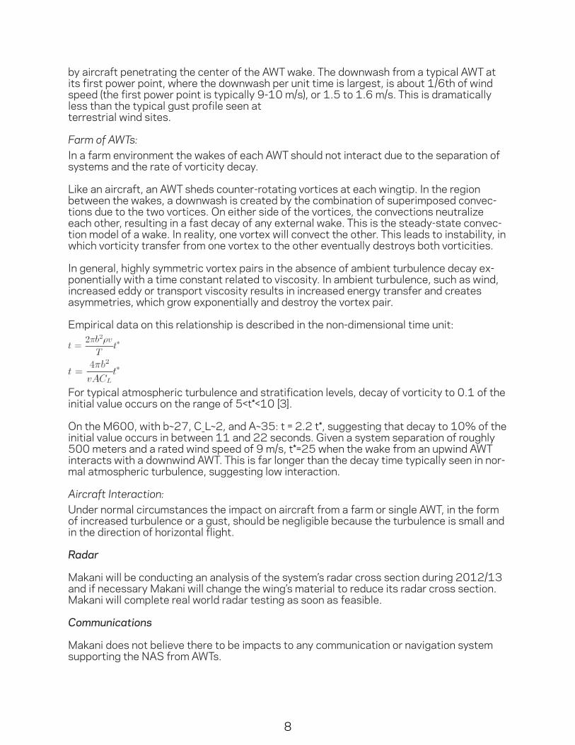
Empirical data on this relationship is described in the non-dimensional time unit:
For typical atmospheric turbulence and stratification levels, decay of vorticity to 0.1 of the initial value occurs on the range of 5<t*<10 [3].
On the M600, with b~27, C_L~2, and A~35: t = 2.2 t*, suggesting that decay to 10% of the initial value occurs in between 11 and 22 seconds. Given a system separation of roughly 500 meters and a rated wind speed of 9 m/s, t*=25 when the wake from an upwind AWT interacts with a downwind AWT. This is far longer than the decay time typically seen in nor-mal atmospheric turbulence, suggesting low interaction.
Aircraft Interaction:Under normal circumstances the impact on aircraft from a farm or single AWT, in the form of increased turbulence or a gust, should be negligible because the turbulence is small and in the direction of horizontal flight.
Radar
Makani will be conducting an analysis of the system’s radar cross section during 2012/13 and if necessary Makani will change the wing’s material to reduce its radar cross section. Makani will complete real world radar testing as soon as feasible.
Communications
Makani does not believe there to be impacts to any communication or navigation systemsupporting the NAS from AWTs.

9
Siting
AWTs have increased siting flexibility (as opposed to conventional wind turbines), allowing them to be sited away from NAS facilities.
2.7 Testing Needs
Current Testing
Makani will comply with all FAA requests:• Airborne operations of AWES should be temporary in nature for testing and data
collection purposes only• Single AWES devices only (e.g.—no “farms” or multiple simultaneous testing)• AWES should be limited to a single fixed location (e.g.—no mobile ground facilities• Testing is confined to heights at or below 499 feet above ground level (AGL)• Airborne flight testing of AWES will only occur during daylight hours • AWES will be made conspicuous to the flying public through NOTAMS.
Upcoming Testing Needs
To ensure the safety of AWTs, in depth reliability testing will need to be performed, starting within the next year.
Within the next year Makani will need to test:• At night• Over long periods of time (weeks, months)
Within the next two years Makani will need to test:• Up to 2,000 feet AGL• Multiple system “farm” environments
Figure 8. Makani’s testing team carries Wing 7 to the test site at Sherman Island, CA, June 2011. Makani Power is a leader in airborne wind energy technology and has a proven track record of technical accomplishments, including high speed, autono-mous flight; power genera-tion and fully autonomous flight using a sophisticated set of components designed and built by Makani.

10
2.8 References
1) BRS Aerospace, Parachute Specifications: accessed on January 7, 2010. http://www.brsparachutes.com/files/brspara¬chutes/files/BRS%206%20Specifications.pdf 2) Sovacool, BK. “Contextualizing Avian Mortality: A Preliminary Appraisal of Bird and Bat Fatalities from Wind, Fossil-Fuel, and Nuclear Electricity,” Energy Policy 37(6) (June, 2009): 2241-2248. 3) Holzapfel, F. “Probabilistic Two-Phase Wake Vortex Decay and Transport Model,” Journal of Aircraft, Volume 40 #2, 2003: 323-331