maintenance & service guide - gfk etilizecontent.etilize.com/user-manual/1024083241.pdftext set...
TRANSCRIPT
Maintenance & Service Guide
HP TouchSmart Elite 7320 All-in-One BusinessPC

© Copyright 2011, 2012 Hewlett-PackardDevelopment Company, L.P. Theinformation contained herein is subject tochange without notice.
Microsoft and Windows are trademarks ofMicrosoft Corporation in the U.S. and othercountries.
The only warranties for HP products andservices are set forth in the expresswarranty statements accompanying suchproducts and services. Nothing hereinshould be construed as constituting anadditional warranty. HP shall not be liablefor technical or editorial errors or omissionscontained herein.
This document contains proprietaryinformation that is protected by copyright.No part of this document may bephotocopied, reproduced, or translated toanother language without the prior writtenconsent of Hewlett-Packard Company.
Maintenance & Service Guide
HP TouchSmart Elite 7320 All-in-OneBusiness PC
Fourth Edition (December 2012)
First Edition (September 2011)
Document Part Number: 670575-004

About This Book
WARNING! Text set off in this manner indicates that failure to follow directions could result in bodilyharm or loss of life.
CAUTION: Text set off in this manner indicates that failure to follow directions could result indamage to equipment or loss of information.
NOTE: Text set off in this manner provides important supplemental information.
iii

Table of contents
1 Product Features ............................................................................................................................................ 1
Overview .............................................................................................................................................. 1
Front Components ................................................................................................................................ 3
Side Components ................................................................................................................................. 4
Rear Components ................................................................................................................................ 5
2 Installing and Customizing the Software ...................................................................................................... 6
Installing the Operating System ........................................................................................................... 6
Downloading Microsoft Windows Updates ........................................................................................... 6
Installing or Upgrading Device Drivers (Windows systems) ................................................................. 7
Accessing Disk Image (ISO) Files ........................................................................................................ 7
Protecting the Software ........................................................................................................................ 7
3 Computer Setup (F10) Utility ......................................................................................................................... 8
Computer Setup (F10) Utilities ............................................................................................................. 8
Using Computer Setup (F10) Utilities .................................................................................. 9
Computer Setup—File ....................................................................................................... 10
Computer Setup—Storage ................................................................................................ 11
Computer Setup—Security ................................................................................................ 13
Computer Setup—Power ................................................................................................... 16
Computer Setup—Advanced ............................................................................................. 17
4 Serial ATA (SATA) Drive Guidelines and Features .................................................................................... 18
SATA Hard Drives .............................................................................................................................. 18
SATA Hard Drive Cables .................................................................................................................... 18
SATA Data Cable .............................................................................................................. 18
SMART ATA Drives ............................................................................................................................ 19
Hard Drive Capacities ........................................................................................................................ 19
5 Routine Care and Disassembly Preparation .............................................................................................. 20
Electrostatic Discharge Information .................................................................................................... 20
v

Generating Static ............................................................................................................... 20
Preventing Electrostatic Damage to Equipment ................................................................ 21
Personal Grounding Methods and Equipment ................................................................... 21
Grounding the Work Area .................................................................................................. 22
Recommended Materials and Equipment .......................................................................... 22
Operating Guidelines .......................................................................................................................... 23
Routine Care ...................................................................................................................................... 23
General Cleaning Safety Precautions ................................................................................ 23
Cleaning the Computer Case ............................................................................................ 23
Cleaning the Keyboard ...................................................................................................... 24
Cleaning the Monitor .......................................................................................................... 24
Cleaning the Mouse ........................................................................................................... 25
Service Considerations ...................................................................................................................... 25
Tools and Software Requirements .................................................................................... 25
Screws ............................................................................................................................... 25
Cables and Connectors ..................................................................................................... 25
Hard Drives ........................................................................................................................ 26
Lithium Coin Cell Battery ................................................................................................... 26
6 Illustrated parts catalog ............................................................................................................................... 27
Computer major components ............................................................................................................. 27
Boards, memory, processors ............................................................................................................. 28
Mass storage devices ......................................................................................................................... 29
Cables ................................................................................................................................................ 30
Misc parts ........................................................................................................................................... 31
Keyboards (not illustrated) ................................................................................................................. 32
Sequential part number listing ............................................................................................................ 33
7 Removal and Replacement Procedures All-in One (AIO) Chassis ........................................................... 40
Preparing to Disassemble the Computer ........................................................................................... 40
Rear Cover ......................................................................................................................................... 41
Stand .................................................................................................................................................. 42
Memory Cover .................................................................................................................................... 43
Memory .............................................................................................................................................. 45
Optical Drive ....................................................................................................................................... 47
Hard Drive .......................................................................................................................................... 49
Converter Board ................................................................................................................................. 52
Touch Controller Board ...................................................................................................................... 54
Webcam Module ................................................................................................................................ 56
Speakers ............................................................................................................................................ 58
System Board Cover .......................................................................................................................... 60
vi

WLAN Module .................................................................................................................................... 62
TV Tuner Module ................................................................................................................................ 64
Heat sinks (Thermal Modules) ........................................................................................................... 66
Processor ........................................................................................................................................... 68
Graphics Card .................................................................................................................................... 70
Fan ..................................................................................................................................................... 72
VESA Cover with Kensington Lock Bracket ....................................................................................... 74
Optical and Hard Drive Cables and Connector .................................................................................. 76
Coaxal Cable Connector .................................................................................................................... 78
System Board ..................................................................................................................................... 80
Display Cable ..................................................................................................................................... 83
Front Bezel and Display Panel ........................................................................................................... 85
Cable Routing ..................................................................................................................................... 91
Appendix A Troubleshooting Without Diagnostics ...................................................................................... 92
Safety and Comfort ............................................................................................................................ 92
Before You Call for Technical Support ............................................................................................... 92
Helpful Hints ....................................................................................................................................... 93
Solving General Problems .................................................................................................................. 95
Solving Power Problems .................................................................................................................... 98
Solving Diskette Problems ................................................................................................................. 99
Solving Hard Drive Problems ........................................................................................................... 102
Solving Media Card Reader Problems ............................................................................................. 105
Solving Display Problems ................................................................................................................. 107
Solving Audio Problems ................................................................................................................... 111
Solving Printer Problems .................................................................................................................. 113
Solving Keyboard and Mouse Problems .......................................................................................... 114
Solving Hardware Installation Problems ........................................................................................... 116
Solving Network Problems ............................................................................................................... 117
Solving Memory Problems ............................................................................................................... 121
Solving Processor Problems ............................................................................................................ 122
Solving CD-ROM and DVD Problems .............................................................................................. 123
Solving USB Flash Drive Problems .................................................................................................. 125
Solving Front Panel Component Problems ...................................................................................... 126
Solving Internet Access Problems .................................................................................................... 126
Solving Software Problems .............................................................................................................. 129
Contacting Customer Support .......................................................................................................... 130
Appendix B POST Error Messages .............................................................................................................. 131
POST Numeric Codes and Text Messages ..................................................................................... 132
Interpreting POST Diagnostic Front Panel LEDs and Audible Codes .............................................. 139
vii

Appendix C Connector Pin Assignments .................................................................................................... 142
Ethernet BNC ................................................................................................................................... 142
USB .................................................................................................................................................. 142
Microphone ....................................................................................................................................... 142
Headphone ....................................................................................................................................... 143
Line-in Audio .................................................................................................................................... 143
Line-out Audio .................................................................................................................................. 143
Appendix D Power Cord Set Requirements ................................................................................................ 144
General Requirements ..................................................................................................................... 144
Japanese Power Cord Requirements .............................................................................................. 144
Country-Specific Requirements ........................................................................................................ 145
Appendix E Specifications ............................................................................................................................ 146
All-in One Models ............................................................................................................................. 146
Index ................................................................................................................................................................. 147
viii
1 Product Features
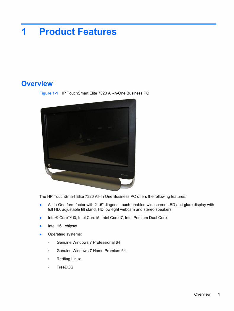
OverviewFigure 1-1 HP TouchSmart Elite 7320 All-in-One Business PC
The HP TouchSmart Elite 7320 All-In One Business PC offers the following features:
● All-in-One form factor with 21.5” diagonal touch-enabled widescreen LED anti-glare display withfull HD, adjustable tilt stand, HD low-light webcam and stereo speakers
● Intel® Core™ i3, Intel Core i5, Intel Core i7, Intel Pentium Dual Core
● Intel H61 chipset
● Operating systems:
◦ Genuine Windows 7 Professional 64
◦ Genuine Windows 7 Home Premium 64
◦ Redflag Linux
◦ FreeDOS
Overview 1

● Graphics:
◦ Integrated: Intel HD Graphics
◦ Discrete: NVIDIA GeForce 5xx (1GB); NVIDIA GeForce GT 5xx (2GB); AMD Radeon HD6450A (1GB); AMD Radeon HD 6550A (2GB)
NOTE: Discrete graphics not available in the Americas region.
● Integrated Realtek RTL8171EH Gigabit Ethernet Controller
● HP Wireless 802.11 b/g/n Mini Card (2x2)
● HP Wireless 802.11b/g/n Mini Card (2x2) with Bluetooth Combo
● (2) SODIMM slots, up to 8 GB DDR3 non-ECC SDRAM (2 X 4 GB)
● Hard drives:
◦ 250GB to 2TB SATA 6.0Gb/s (7200 rpm)
◦ 1.5TB to 2TB SATA 6.0Gb/s (5400 rpm)
◦ 250GB to 2TB SATA 3.0Gb/s (7200 rpm)
◦ 1.5TB to 2TB SATA 3.0Gb/s (5400 rpm)
● HP Slim Tray-load DVD Writer, HP Slim Tray-load Blu-ray Combo Writer
● Mini PCIe x1 slot
● (4) rear USB 2.0; (2) side USB 3.0; Stereo audio headphone jack; Stereo audio line out; Coaxialcables for tuner; IR blaster; Power connector; RJ-45 Ethernet; 6-in-1 Media Card Reader
● Integrated IDT 92HD91 with Beats Audio™ and high-performance stereo speakers
● Power:
◦ External 150W for UMA graphics cards
◦ External 180W for MXM graphics cards
NOTE: Discrete graphics not available in the Americas region.
2 Chapter 1 Product Features

Front ComponentsFigure 1-2 Front Components
Table 1-1 Front Components
Component Component
1 Dual microphone array 5 Stereo speakers
2 Fixed 2-MP HD low-light webcam 6 Adjustable tilt stand
3 Webcam LED indicator 7 HP Wireless Keyboard
4 21.5-inch touch-enabled diagonal widescreen LEDanti-glare display with full HD
8 HP Wireless Mouse
Front Components 3

Side ComponentsFigure 1-3 Side Components
Table 1-2 Side Components
Component Component
1 Optical Disk Drive 5 2 USB 2.0 ports
2 Hard Disk Drive LED Indicator 6 MIC Port
3 Media Card Reader LED Indicator 7 Headphone Port
4 6-in-1 Media Card Reader
4 Chapter 1 Product Features
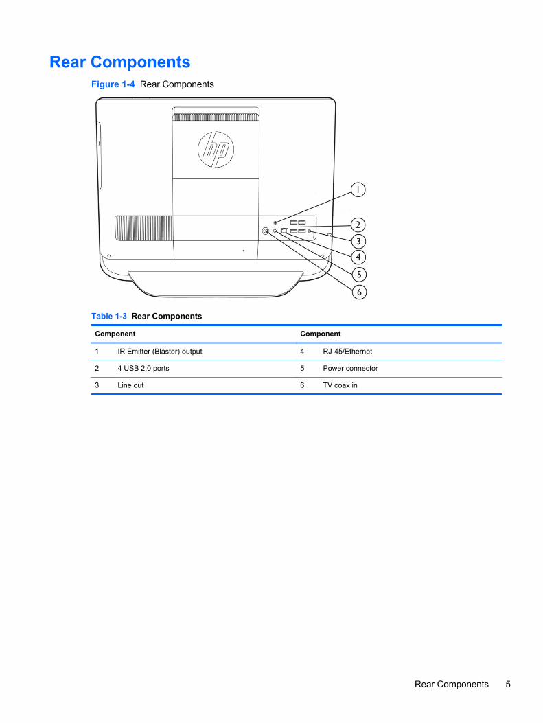
Rear ComponentsFigure 1-4 Rear Components
Table 1-3 Rear Components
Component Component
1 IR Emitter (Blaster) output 4 RJ-45/Ethernet
2 4 USB 2.0 ports 5 Power connector
3 Line out 6 TV coax in
Rear Components 5

2 Installing and Customizing theSoftware
If your computer was not shipped with a Microsoft operating system, some portions of thisdocumentation do not apply. Additional information is available in online help after you install theoperating system.
NOTE: If the computer was shipped with Windows 7 loaded, you will be prompted to register thecomputer with HP Total Care before installing the operating system. You will see a brief moviefollowed by an online registration form. Fill out the form, click the Begin button, and follow theinstructions on the screen.
CAUTION: Do not add optional hardware or third-party devices to the computer until the operatingsystem is successfully installed. Doing so may cause errors and prevent the operating system frominstalling properly.
NOTE: Be sure there is a 10.2-cm (4-inch) clearance at the back of the unit and above the monitorto permit the required airflow.
Installing the Operating SystemThe first time you turn on the computer, the operating system is installed automatically. This processtakes about 5 to 10 minutes, depending on which operating system is being installed. Carefully readand follow the instructions on the screen to complete the installation.
CAUTION: Once the automatic installation has begun, DO NOT TURN OFF THE COMPUTERUNTIL THE PROCESS IS COMPLETE. Turning off the computer during the installation process maydamage the software that runs the computer or prevent its proper installation.
NOTE: If the computer shipped with more than one operating system language on the hard drive,the installation process could take up to 60 minutes.
If your computer was not shipped with a Microsoft operating system, some portions of thisdocumentation do not apply. Additional information is available in online help after you install theoperating system.
Downloading Microsoft Windows Updates1. To set up your Internet connection, click Start > Internet Explorer and follow the instructions on
the screen.
2. Once an Internet connection has been established, click the Start button.
6 Chapter 2 Installing and Customizing the Software

3. Select the All Programs menu.
4. Click on the Windows Update link.
The Windows Update screen appears. Click view available updates and make sure all criticalupdates are selected. Click the Install button and follow the instructions on the screen.
It is recommended that you install all of the critical updates and service packs.
5. After the updates have been installed, Windows will prompt you to reboot the machine. Be sureto save any files or documents that you may have open before rebooting. Then select Yes toreboot the machine.
Installing or Upgrading Device Drivers (Windowssystems)
When installing optional hardware devices after the operating system installation is complete, youmust also install the drivers for each of the devices.
If prompted for the i386 directory, replace the path specification with C:\i386, or use the Browsebutton in the dialog box to locate the i386 folder. This action points the operating system to theappropriate drivers.
Obtain the latest support software, including support software for the operating system fromhttp://www.hp.com/support. Select your country and language, select Download drivers andsoftware (and firmware), enter the model number of the computer, and press Enter.
Accessing Disk Image (ISO) FilesThere are disk image files (ISO files) included on your PC that contain the installation software foradditional software. These CD image files are located in the folder C:\SWSetup\ISOs. Each .iso filecan be burned to CD media to create an installation CD. It is recommended that these disks becreated and the software installed in order to get the most from your PC. The software and image filenames are:
● Corel WinDVD SD and BD – installation software for WinDVD – used to play DVD movies
● HP Insight Diagnostics OR Vision Diagnostics – software to perform diagnostic activities on yourPC
Protecting the SoftwareTo protect the software from loss or damage, keep a backup copy of all system software,applications, and related files stored on the hard drive. Refer to the operating system or backup utilitydocumentation for instructions on making backup copies of your data files.
Installing or Upgrading Device Drivers (Windows systems) 7

3 Computer Setup (F10) Utility
Computer Setup (F10) UtilitiesUse Computer Setup (F10) Utility to do the following:
● Change factory default settings.
● Set the system date and time.
● Set, view, change, or verify the system configuration, including settings for processor, graphics,memory, audio, storage, communications, and input devices.
● Modify the boot order of bootable devices such as hard drives, optical drives, or USB flashmedia devices.
● Enable Quick Boot, which is faster than Full Boot but does not run all of the diagnostic tests runduring a Full Boot. You can set the system to:
❑ always Quick Boot (default);
❑ periodically Full Boot (from every 1 to 30 days); or
❑ always Full Boot.
● Select Post Messages Enabled or Disabled to change the display status of Power-On Self-Test(POST) messages. Post Messages Disabled suppresses most POST messages, such asmemory count, product name, and other non-error text messages. If a POST error occurs, theerror is displayed regardless of the mode selected. To manually switch to Post MessagesEnabled during POST, press any key (except F1 through F12).
● Establish an Ownership Tag, the text of which is displayed each time the system is turned on orrestarted.
● Enter the Asset Tag or property identification number assigned by the company to this computer.
● Enable the power-on password prompt during system restarts (warm boots) as well as duringpower-on.
● Establish a setup password that controls access to the Computer Setup (F10) Utility and thesettings described in this section.
● Secure integrated I/O functionality, including USB, audio, or embedded NIC, so that they cannotbe used until they are unsecured.
● Enable or disable removable media boot ability.
8 Chapter 3 Computer Setup (F10) Utility

● Solve system configuration errors detected but not automatically fixed during the Power-On Self-Test (POST).
● Replicate the system setup by saving system configuration information on a USB flash drive andrestoring it on one or more computers.
● Execute self-tests on a specified ATA hard drive (when supported by drive).
● Enable or disable DriveLock security (when supported by drive).
Using Computer Setup (F10) Utilities
Computer Setup can be accessed only by turning the computer on or restarting the system.To access the Computer Setup Utilities menu, complete the following steps:
1. Turn on or restart the computer.
2. Press Esc while the “Press the ESC key for Startup Menu” message is displayed at the bottomof the screen.
NOTE: If you do not press Esc at the appropriate time, you must restart the computer andagain press Esc when the monitor light turns green to access the utility.
3. Press F10 to enter Computer Setup.
4. A choice of five headings appears in the Computer Setup Utilities menu: File, Storage, Security,Power, and Advanced.
5. Use the arrow (left and right) keys to select the appropriate heading. Use the arrow (up anddown) keys to select the option you want, then press Enter. To return to the Computer SetupUtilities menu, press Esc.
6. To apply and save changes, select File > Save Changes and Exit.
● If you have made changes that you do not want applied, select Ignore Changes and Exit.
● To reset to factory settings or previously saved default settings (some models), selectApply Defaults and Exit. This option will restore the original factory system defaults.
CAUTION: Do NOT turn the computer power OFF while the BIOS is saving the Computer Setup(F10) changes because the CMOS could become corrupted. It is safe to turn off the computer onlyafter exiting the F10 Setup screen.
Computer Setup (F10) Utilities 9
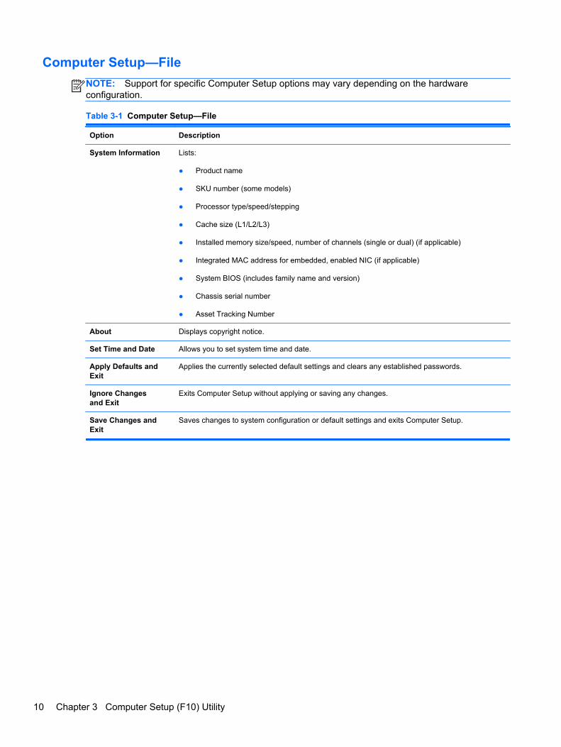
Computer Setup—File
NOTE: Support for specific Computer Setup options may vary depending on the hardwareconfiguration.
Table 3-1 Computer Setup—File
Option Description
System Information Lists:
● Product name
● SKU number (some models)
● Processor type/speed/stepping
● Cache size (L1/L2/L3)
● Installed memory size/speed, number of channels (single or dual) (if applicable)
● Integrated MAC address for embedded, enabled NIC (if applicable)
● System BIOS (includes family name and version)
● Chassis serial number
● Asset Tracking Number
About Displays copyright notice.
Set Time and Date Allows you to set system time and date.
Apply Defaults andExit
Applies the currently selected default settings and clears any established passwords.
Ignore Changesand Exit
Exits Computer Setup without applying or saving any changes.
Save Changes andExit
Saves changes to system configuration or default settings and exits Computer Setup.
10 Chapter 3 Computer Setup (F10) Utility

Computer Setup—Storage
NOTE: Support for specific Computer Setup options may vary depending on the hardwareconfiguration.
Table 3-2 Computer Setup—Storage
Option Description
Device Configuration Lists all installed BIOS-controlled storage devices.
When a device is selected, detailed information and options are displayed. The following optionsmay be presented:
Hard Disk: Size, model, firmware version, serial number.
Emulation type has the following choices:
● None (prevents BIOS data accesses and disables it as a boot device)
● Hard Disk (treated as a hard disk)
CD-ROM: Model, firmware version, serial number.
Storage Options SATA Emulation
Allows you to choose how the SATA controller and devices are accessed by the operatingsystem. There are two supported options: IDE and AHCI.
The default is set based on the Feature Byte code stored in the SMBIOS Type11/Feature Bytestring as follows:
Feature Byte Default
FBC_SATA_RAID RAID
FBC_SATA_AHCI AHCI
FBC_SATA_IDE IDE
Otherwise (none found) Platform-dependent - to be implemented by BIOS Integrator
IDE - This is the most backwards-compatible setting of the three options. Operating systemsusually do not require additional driver support in IDE mode.
AHCI (default option) - Allows operating systems with AHCI device drivers loaded to takeadvantage of more advanced features of the SATA controller.
Computer Setup (F10) Utilities 11
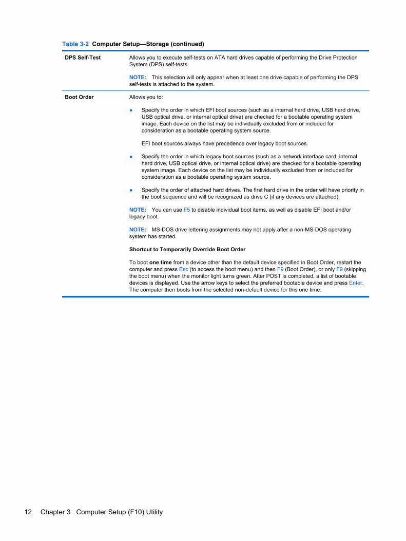
Table 3-2 Computer Setup—Storage (continued)
DPS Self-Test Allows you to execute self-tests on ATA hard drives capable of performing the Drive ProtectionSystem (DPS) self-tests.
NOTE: This selection will only appear when at least one drive capable of performing the DPSself-tests is attached to the system.
Boot Order Allows you to:
● Specify the order in which EFI boot sources (such as a internal hard drive, USB hard drive,USB optical drive, or internal optical drive) are checked for a bootable operating systemimage. Each device on the list may be individually excluded from or included forconsideration as a bootable operating system source.
EFI boot sources always have precedence over legacy boot sources.
● Specify the order in which legacy boot sources (such as a network interface card, internalhard drive, USB optical drive, or internal optical drive) are checked for a bootable operatingsystem image. Each device on the list may be individually excluded from or included forconsideration as a bootable operating system source.
● Specify the order of attached hard drives. The first hard drive in the order will have priority inthe boot sequence and will be recognized as drive C (if any devices are attached).
NOTE: You can use F5 to disable individual boot items, as well as disable EFI boot and/orlegacy boot.
NOTE: MS-DOS drive lettering assignments may not apply after a non-MS-DOS operatingsystem has started.
Shortcut to Temporarily Override Boot Order
To boot one time from a device other than the default device specified in Boot Order, restart thecomputer and press Esc (to access the boot menu) and then F9 (Boot Order), or only F9 (skippingthe boot menu) when the monitor light turns green. After POST is completed, a list of bootabledevices is displayed. Use the arrow keys to select the preferred bootable device and press Enter.The computer then boots from the selected non-default device for this one time.
12 Chapter 3 Computer Setup (F10) Utility

Computer Setup—Security
NOTE: Support for specific Computer Setup options may vary depending on the hardwareconfiguration.
Table 3-3 Computer Setup—Security
Option Description
Setup Password Allows you to set and enable a setup (administrator) password.
NOTE: If the setup password is set, it is required to change Computer Setup options, flash theROM, and make changes to certain plug and play settings under Windows.
See the Desktop Management Guide for more information.
Power-On Password Allows you to set and enable a power-on password. The power-on password prompt appearsafter a power cycle. If the user does not enter the correct power-on password, the unit will notboot.
NOTE: This password does not appear on warm boots , such as Ctrl+Alt+Delete or Restartfrom Windows, unless enabled in Password Options (see below).
See the Desktop Management Guide for more information.
Password Options
(Appears only if apower-on password orsetup password is set.)
Allows you to:
● Lock legacy resources (appears if a setup password is set). Default is enable.
● Enable/Disable Setup Browse Mode (appears if a setup password is set) (allows viewing, butnot changing, the F10 Setup Options without entering setup password). Default is enable.
● Specify whether the password is required for warm boot (Ctrl+Alt+Delete) (appears if apower-on password is set). Default is enable.
● Enable/disable network server mode (appears if a power-on password is set). Default isdisable.
Device Security Allows you to set Device Available/Device Hidden for:
● Embedded Security Device (some models)
● System Audio
● Network Controller (some models)
● SATA connectors/devices
USB Security Allows you to enable or disable groups of USB ports or individual USB ports. Default is deviceavailable.
● Front USB Ports
● Rear USB Ports
● internal USB Ports
Slot Security Allows you to disable or enable the PCI, PCI Express, and MiniCard slots (as applicable). Defaultis enable.
Network Boot Enables/disables the computer’s ability to boot from an operating system installed on a networkserver. (Feature available on NIC models only; the network controller must be either a PCIExpress expansion card or embedded on the system board.) Default is enable.
Computer Setup (F10) Utilities 13

Table 3-3 Computer Setup—Security (continued)
System IDs Allows you to view:
● Product Name
● Serial number
● Universal Unique Identifier (UUID) number. The UUID can only be updated if the currentchassis serial number is invalid. (These ID numbers are normally set in the factory and areused to uniquely identify the system.)
● SKU Number
● Family Name
● Asset tag (18-byte identifier), a property identification number assigned by the company tothe computer.
● Feature Byte
● Build ID
● Keyboard locale setting for System ID entry
System Security(some models: theseoptions are hardwaredependent)
Data Execution Prevention (enable/disable) - Helps prevent operating system security breaches.Default is enabled.
Virtualization Technology (VTx/VTd)(some models) (enable/disable) - Controls the virtualizationfeatures of the processor and DMA remapping features of the chipset. Changing this settingrequires turning the computer off and then back on. Default is disabled.
PAVP (Models with Blu-ray drives) (disabled/min/max) - PAVP enables the Protected Audio VideoPath in the Chipset. This may allow viewing of some protected high definition content that wouldotherwise be prohibited from playback. Selecting Max will assign 96 Megabytes of systemmemory exclusively to PAVP.
Intel TXT (LT) Support (some models) (enable/disable) - Controls the underlying processor andchipset features needed to support a virtual appliance. Changing this setting requires turning thecomputer off and then back on. Default is disabled. To enable this feature you must enable thefollowing features:
● Embedded Security Device Support
● Virtualization Technology
● Virtualization Technology Directed I/O
14 Chapter 3 Computer Setup (F10) Utility

Table 3-3 Computer Setup—Security (continued)
Embedded Security Device (some models) (enable/disable) - Permits activation and deactivationof the Embedded Security Device. Changing this setting requires turning the computer off andthen back on.
NOTE: To configure the Embedded Security Device, a Setup password must be set.
● Reset to Factory Settings (some models) (Do not reset/Reset) - Resetting to factory defaultswill erase all security keys. Changing this setting requires turning the computer off and thenback on. Default is Do not reset.
CAUTION: The embedded security device is a critical component of many securityschemes. Erasing the security keys will prevent access to data protected by the EmbeddedSecurity Device. Choosing Reset to Factory Settings may result in significant data loss.
OS management of Embedded Security Device (some models) (enable/disable) - This optionallows the user to limit operating system control of the Embedded Security Device. Changing thissetting requires turning the computer off and then back on. This option allows the user to limit OScontrol of the Embedded Security Device. Default is enable.
● Reset of Embedded Security Device through OS (some models) (enable/disable) - Thisoption allows the user to limit the operating system ability to request a Reset to FactorySettings of the Embedded Security Device. Changing this setting requires turning thecomputer off and then back on. Default is disable.
NOTE: To enable this option, a Setup password must be set.
DriveLock Security Allows you to assign or modify a master or user password for hard drives. When this feature isenabled, the user is prompted to provide one of the DriveLock passwords during POST. If neitheris successfully entered, the hard drive will remain inaccessible until one of the passwords issuccessfully provided during a subsequent cold-boot sequence.
NOTE: This selection will only appear when at least one drive that supports the DriveLockfeature is attached to the system.
Computer Setup (F10) Utilities 15

Computer Setup—Power
NOTE: Support for specific Computer Setup options may vary depending on the hardwareconfiguration.
Table 3-4 Computer Setup—Power
Option Description
Hardware PowerManagement
SATA Power Management – Enables or disables SATA bus and/or device power management.Default is enabled.
S5 Maximum Power Savings – Turns off power to all nonessential hardware when system is off tomeet EUP Lot 6 requirement of less than 1 Watt power usage. Default is enabled.
S5 Wake on LAN (enable/disable).
● To disable Wake on LAN during the off state (S5), use the arrow (left and right) keys toselect the Advanced > Device Options menu and set the S5 Wake on LAN feature toDisable. This obtains the lowest power consumption available on the computer during S5. Itdoes not affect the ability of the computer to Wake on LAN from suspend or hibernation, butwill prevent it from waking from S5 via the network. It does not affect operation of thenetwork connection while the computer is on.
● If a network connection is not required, completely disable the network controller (NIC) byusing the arrow (left and right) keys to select the Security > Device Security menu. Set theNetwork Controller option to Device Hidden. This prevents the network controller from beingused by the operating system and reduces the power used by the computer in S5.
Thermal Displays the CPU fan speed (RPMs).
16 Chapter 3 Computer Setup (F10) Utility

Computer Setup—Advanced
NOTE: Support for specific Computer Setup options may vary depending on the hardwareconfiguration.
Table 3-5 Computer Setup—Advanced
Option Heading
Power-On Options Allows you to set:
● POST messages (enable/disable). Default is disabled.
● After Power Loss (off/on/previous state). Default is Power off. Setting this option to:
◦ Power off—causes the computer to remain powered off when power is restored.
◦ Power on—causes the computer to power on automatically as soon as power isrestored.
◦ Previous state—causes the computer to power on automatically as soon as power isrestored, if it was on when power was lost.
NOTE: If you turn off power to the computer using the switch on a power strip, you will not beable to use the suspend/sleep feature or the Remote Management features.
● POST Delay (in seconds). Enabling this feature will add a user-specified delay to the POSTprocess. This delay is sometimes needed for hard disks on some PCI cards that spin up veryslowly, so slowly that they are not ready to boot by the time POST is finished. The POSTdelay also gives you more time to select F10 to enter Computer (F10) Setup. Default isNone.
BIOS Power-On Allows you to set the computer to turn on automatically at a time you specify.
Bus Options On some models, allows you to enable or disable:
● PCI SERR# Generation. Default is enable.
● PCI VGA Palette Snooping, which sets the VGA palette snooping bit in PCI configurationspace; only needed when more than one graphics controller is installed. Default is disable.
Device Options Allows you to set:
● Num Lock State at Power-On (off/on). Default is off.
● Multi-Processor (enable/disable). Use this option to disable multi-processor support underthe OS. Default is enabled.
● Hyper-threading (enable/disable) (some models). Use this option to disable processorhyperthreading.
● Integrated Video (enable/disable). Use this option to disable the integrated video controllerwhen another video controller is present in the system. Default is enabled.
● NIC PXE Option ROM Download (PXE, iSCSI, disabled). The BIOS contains an embeddedNIC option ROM to allow the unit to boot through the network to a PXE server. This istypically used to download a corporate image to a hard drive. The NIC option ROM takes upmemory space below 1MB commonly referred to as DOS Compatibility Hole (DCH) space.This space is limited. This F10 option will allow users to disable the downloading of thisembedded NIC option ROM thus giving more DCH space for additional PCI cards which mayneed option ROM space. The default will be to have the NIC option-ROM-enabled. Default isPXE.
Computer Setup (F10) Utilities 17

4 Serial ATA (SATA) Drive Guidelinesand Features
NOTE: HP only supports the use of SATA hard drives on these models of computer. No ParallelATA (PATA) drives are supported.
SATA Hard Drives
Serial ATA Hard Drive Characteristics
Number of pins/conductors in data cable 7/7
Number of pins in power cable 15
Maximum data cable length 39.37 in (100 cm)
Data interface voltage differential 400-700 mV
Drive voltages 3.3 V, 5 V, 12 V
Jumpers for configuring drive N/A
Data transfer rate 3.0 Gb/s
SATA Hard Drive Cables
SATA Data Cable
Always use an HP approved SATA 3.0 Gb/s cable as it is fully backwards compatible with the SATA1.5 Gb/s drives.
Current HP desktop products ship with SATA 3.0 Gb/s hard drives.
SATA data cables are susceptible to damage if overflexed. Never crease a SATA data cable andnever bend it tighter than a 30 mm (1.18 in) radius.
The SATA data cable is a thin, 7-pin cable designed to transmit data for only a single drive.
18 Chapter 4 Serial ATA (SATA) Drive Guidelines and Features

SMART ATA DrivesThe Self Monitoring Analysis and Recording Technology (SMART) ATA drives for the HP PersonalComputers have built-in drive failure prediction that warns the user or network administrator of animpending failure or crash of the hard drive. The SMART drive tracks fault prediction and failureindication parameters such as reallocated sector count, spin retry count, and calibration retry count. Ifthe drive determines that a failure is imminent, it generates a fault alert.
Hard Drive CapacitiesThe combination of the file system and the operating system used in the computer determines themaximum usable size of a drive partition. A drive partition is the largest segment of a drive that maybe properly accessed by the operating system. A single hard drive may therefore be subdivided into anumber of unique drive partitions in order to make use of all of its space.
Because of the differences in the way that drive sizes are calculated, the size reported by theoperating system may differ from that marked on the hard drive or listed in the computer specification.Drive size calculations by drive manufacturers are bytes to the base 10 while calculations byMicrosoft are bytes to the base 2.
Drive/Partition Capacity Limits
Maximum Size
File System Controller Type Operating System Partition Drive
FAT 32 ATA Windows 7 32 GB 2 TB
NTFS ATA Windows 7 2 TB 2 TB
SMART ATA Drives 19

5 Routine Care and DisassemblyPreparation
This chapter provides general service information for the computer. Adherence to the procedures andprecautions described in this chapter is essential for proper service.
CAUTION: When the computer is plugged into an AC power source, voltage is always applied tothe system board. You must disconnect the power cord from the power source before opening thecomputer to prevent system board or component damage.
Electrostatic Discharge InformationA sudden discharge of static electricity from your finger or other conductor can destroy static-sensitivedevices or microcircuitry. Often the spark is neither felt nor heard, but damage occurs. An electronicdevice exposed to electrostatic discharge (ESD) may not appear to be affected at all and can workperfectly throughout a normal cycle. The device may function normally for a while, but it has beendegraded in the internal layers, reducing its life expectancy.
Networks built into many integrated circuits provide some protection, but in many cases, thedischarge contains enough power to alter device parameters or melt silicon junctions.
Generating Static
The following table shows that:
● Different activities generate different amounts of static electricity.
● Static electricity increases as humidity decreases.
Relative Humidity
Event 55% 40% 10%
Walking across carpet
Walking across vinyl floor
Motions of bench worker
Removing DIPs* from plastic tube
7,500 V
3,000 V
400 V
400 V
15,000 V
5,000 V
800 V
700 V
35,000 V
12,000 V
6,000 V
2,000 V
20 Chapter 5 Routine Care and Disassembly Preparation

Removing DIPs* from vinyl tray
Removing DIPs* from Styrofoam
Removing bubble pack from PCB
Packing PCBs in foam-lined box
2,000 V
3,500 V
7,000 V
5,000 V
4,000 V
5,000 V
20,000 V
11,000 V
11,500 V
14,500 V
26,500 V
21,000 V
*These are then multi-packaged inside plastic tubes, trays, or Styrofoam.
NOTE: 700 volts can degrade a product.
Preventing Electrostatic Damage to Equipment
Many electronic components are sensitive to ESD. Circuitry design and structure determine thedegree of sensitivity. The following packaging and grounding precautions are necessary to preventdamage to electric components and accessories.
● To avoid hand contact, transport products in static-safe containers such as tubes, bags, orboxes.
● Protect all electrostatic parts and assemblies with conductive or approved containers orpackaging.
● Keep electrostatic sensitive parts in their containers until they arrive at static-free stations.
● Place items on a grounded surface before removing them from their container.
● Always be properly grounded when touching a sensitive component or assembly.
● Avoid contact with pins, leads, or circuitry.
● Place reusable electrostatic-sensitive parts from assemblies in protective packaging orconductive foam.
Personal Grounding Methods and Equipment
Use the following equipment to prevent static electricity damage to equipment:
● Wrist straps are flexible straps with a maximum of one-megohm ± 10% resistance in the groundcords. To provide proper ground, a strap must be worn snug against bare skin. The ground cordmust be connected and fit snugly into the banana plug connector on the grounding mat orworkstation.
● Heel straps/Toe straps/Boot straps can be used at standing workstations and are compatiblewith most types of shoes or boots. On conductive floors or dissipative floor mats, use them onboth feet with a maximum of one-megohm ± 10% resistance between the operator and ground.
Static Shielding Protection Levels
Method Voltage
Antistatic plastic
Carbon-loaded plastic
Metallized laminate
1,500
7,500
15,000
Electrostatic Discharge Information 21

Grounding the Work Area
To prevent static damage at the work area, use the following precautions:
● Cover the work surface with approved static-dissipative material. Provide a wrist strap connectedto the work surface and properly grounded tools and equipment.
● Use static-dissipative mats, foot straps, or air ionizers to give added protection.
● Handle electrostatic sensitive components, parts, and assemblies by the case or PCB laminate.Handle them only at static-free work areas.
● Turn off power and input signals before inserting and removing connectors or test equipment.
● Use fixtures made of static-safe materials when fixtures must directly contact dissipativesurfaces.
● Keep work area free of nonconductive materials such as ordinary plastic assembly aids andStyrofoam.
● Use field service tools, such as cutters, screwdrivers, and vacuums, that are conductive.
Recommended Materials and Equipment
Materials and equipment that are recommended for use in preventing static electricity include:
● Antistatic tape
● Antistatic smocks, aprons, or sleeve protectors
● Conductive bins and other assembly or soldering aids
● Conductive foam
● Conductive tabletop workstations with ground cord of one-megohm +/- 10% resistance
● Static-dissipative table or floor mats with hard tie to ground
● Field service kits
● Static awareness labels
● Wrist straps and footwear straps providing one-megohm +/- 10% resistance
● Material handling packages
● Conductive plastic bags
● Conductive plastic tubes
● Conductive tote boxes
● Opaque shielding bags
● Transparent metallized shielding bags
● Transparent shielding tubes
22 Chapter 5 Routine Care and Disassembly Preparation

Operating GuidelinesTo prevent overheating and to help prolong the life of the computer:
● Keep the computer away from excessive moisture, direct sunlight, and extremes of heat andcold.
● Operate the computer on a sturdy, level surface. Leave a 10.2-cm (4-inch) clearance on allvented sides of the computer and above the monitor to permit the required airflow.
● Never restrict the airflow into the computer by blocking any vents or air intakes. Do not place thekeyboard, with the keyboard feet down, directly against the front of the desktop unit as this alsorestricts airflow.
● Occasionally clean the air vents on all vented sides of the computer. Lint, dust, and other foreignmatter can block the vents and limit the airflow. Be sure to unplug the computer before cleaningthe air vents.
● Never operate the computer with the cover removed.
● Do not place computers so near each other that they are subject to each other’s re-circulated orpreheated air.
● Keep liquids away from the computer and keyboard.
● Never cover the ventilation slots on the monitor with any type of material.
● Install or enable power management functions of the operating system or other software,including sleep states.
Routine Care
General Cleaning Safety Precautions
1. Never use solvents or flammable solutions to clean the computer.
2. Never immerse any parts in water or cleaning solutions; apply any liquids to a clean cloth andthen use the cloth on the component.
3. Always unplug the computer when cleaning with liquids or damp cloths.
4. Always unplug the computer before cleaning the keyboard, mouse, or air vents.
5. Disconnect the keyboard before cleaning it.
6. Wear safety glasses equipped with side shields when cleaning the keyboard.
Cleaning the Computer Case
Follow all safety precautions in General Cleaning Safety Precautions on page 23 before cleaning thecomputer.
Operating Guidelines 23

To clean the computer case, follow the procedures described below:
● To remove light stains or dirt, use plain water with a clean, lint-free cloth or swab.
● For stronger stains, use a mild dishwashing liquid diluted with water. Rinse well by wiping it witha cloth or swab dampened with clear water.
● For stubborn stains, use isopropyl (rubbing) alcohol. No rinsing is needed as the alcohol willevaporate quickly and not leave a residue.
● After cleaning, always wipe the unit with a clean, lint-free cloth.
● Occasionally clean the air vents on the computer. Lint and other foreign matter can block thevents and limit the airflow.
Cleaning the Keyboard
Follow all safety precautions in General Cleaning Safety Precautions on page 23 before cleaning thekeyboard.
To clean the tops of the keys or the keyboard body, follow the procedures described in Cleaning theComputer Case on page 23.
When cleaning debris from under the keys, review all rules in General Cleaning Safety Precautionson page 23 before following these procedures:
CAUTION: Use safety glasses equipped with side shields before attempting to clean debris fromunder the keys.
● Visible debris underneath or between the keys may be removed by vacuuming or shaking.
● Canned, pressurized air may be used to clean debris from under the keys. Caution should beused as too much air pressure can dislodge lubricants applied under the wide keys.
● If you remove a key, use a specially designed key puller to prevent damage to the keys. Thistool is available through many electronic supply outlets.
CAUTION: Never remove a wide leveled key (like the space bar) from the keyboard. If thesekeys are improperly removed or installed, the keyboard may not function properly.
● Cleaning under a key may be done with a swab moistened with isopropyl alcohol and squeezedout. Be careful not to wipe away lubricants necessary for proper key functions. Use tweezers toremove any fibers or dirt in confined areas. Allow the parts to air dry before reassembly.
Cleaning the Monitor
● Wipe the monitor screen with a clean cloth moistened with water or with a towelette designed forcleaning monitors. Do not use sprays or aerosols directly on the screen; the liquid may seep intothe housing and damage a component. Never use solvents or flammable liquids on the monitor.
● To clean the monitor body follow the procedures in Cleaning the Computer Case on page 23.
24 Chapter 5 Routine Care and Disassembly Preparation
Cleaning the Mouse
Before cleaning the mouse, ensure that the power to the computer is turned off.
● Clean the mouse ball by first removing the retaining plate and the ball from the housing. Pull outany debris from the ball socket and wipe the ball with a clean, dry cloth before reassembly.
● To clean the mouse body, follow the procedures in Cleaning the Computer Case on page 23.
Service ConsiderationsListed below are some of the considerations that you should keep in mind during the disassembly andassembly of the computer.
Tools and Software Requirements
To service the computer, you need the following:
● Torx T-15 screwdriver (HP screwdriver with bits, PN 161946-001)
● Flat-bladed screwdriver (may sometimes be used in place of the Torx screwdriver)
● Phillips #2 screwdriver
● Diagnostics software
● HP tamper-resistant T-15 wrench (Smart Cover FailSafe Key, PN 166527-001) or HP tamper-resistant bits (Smart Cover FailSafe Key, PN 166527-002)
Screws
The screws used in the computer are not interchangeable. They may have standard or metric threadsand may be of different lengths. If an incorrect screw is used during the reassembly process, it candamage the unit. HP strongly recommends that all screws removed during disassembly be kept withthe part that was removed, then returned to their proper locations.
CAUTION: As each subassembly is removed from the computer, it should be placed away from thework area to prevent damage.
Cables and Connectors
Most cables used throughout the unit are flat, flexible cables. These cables must be handled withcare to avoid damage. Apply only the tension required to seat or unseat the cables during insertion orremoval from the connector. Handle cables by the connector whenever possible. In all cases, avoidbending or twisting the cables, and ensure that the cables are routed in such a way that they cannotbe caught or snagged by parts being removed or replaced.
CAUTION: When servicing this computer, ensure that cables are placed in their proper locationduring the reassembly process. Improper cable placement can damage the computer.
Service Considerations 25

Hard Drives
Handle hard drives as delicate, precision components, avoiding all physical shock and vibration. Thisapplies to failed drives as well as replacement spares.
● If a drive must be mailed, place the drive in a bubble-pack mailer or other suitable protectivepackaging and label the package “Fragile: Handle With Care.”
● Do not remove hard drives from the shipping package for storage. Keep hard drives in theirprotective packaging until they are actually mounted in the CPU.
● Avoid dropping drives from any height onto any surface.
● If you are inserting or removing a hard drive, turn off the computer. Do not remove a hard drivewhile the computer is on or in standby mode.
● Before handling a drive, ensure that you are discharged of static electricity. While handling adrive, avoid touching the connector. For more information about preventing electrostaticdamage, refer to Electrostatic Discharge Information on page 20
● Do not use excessive force when inserting a drive.
● Avoid exposing a hard drive to liquids, temperature extremes, or products that have magneticfields such as monitors or speakers.
Lithium Coin Cell Battery
The battery that comes with the computer provides power to the real-time clock and has a minimumlifetime of about three years.
See the appropriate removal and replacement chapter for the chassis you are working on in thisguide for instructions on the replacement procedures.
WARNING! This computer contains a lithium battery. There is a risk of fire and chemical burn if thebattery is handled improperly. Do not disassemble, crush, puncture, short external contacts, disposein water or fire, or expose it to temperatures higher than 140ºF (60ºC). Do not attempt to recharge thebattery.
NOTE: Batteries, battery packs, and accumulators should not be disposed of together with thegeneral household waste. In order to forward them to recycling or proper disposal, please use thepublic collection system or return them to HP, their authorized partners, or their agents.
26 Chapter 5 Routine Care and Disassembly Preparation

6 Illustrated parts catalog
Computer major components
Item Description Spare part number
(1) Front bezel 671590-001
(2) Rear cover 671589-001
(3) System board 671547-001
(4) Stand 671591-001
Display panels (21.5-inch, touch screen, includes bezel; not illustrated)
LGD 671571-001
Samsung 671573-001
AUO 671574-001
Computer major components 27

Boards, memory, processors
Item Description Spare part number
(1) Graphics cards (includes bracket; not available in the Americas region)
NOTE: The Americas region offers only integrated graphics; a discrete graphics optionis not available.
AMD Radeon HD 6450A 1GB DDR3 MXM 3.0A 671561-001
AMD Radeon HD 6450A 1GB DDR3 MXM 3.0A 671563-001
NVIDIA GeForce GT 5xx 1GB DDR3 MXM 3.0A 671564-001
NVIDIA GeForce GT 5xx 2GB DDR3 MXM 3.0A 671565-001
(2) Touch controller board 671570-001
(3) Converter 671569-001
(4) WLAN modules
802.11b/g/n (2x2) WLAN card 654602-001
HP WLAN combo 802.11b/g/n + Bluetooth 2.1 card 652279-001
802.11b/g/n (1x1) WLAN module 634906-001
(5) TV tuners
HP Digital TV Tuner Mini PCIe Card (includes TV tuner and hardware kit; non-BFR) 613990-001
HP Digital TV Tuner Mini PCIe Card (includes TV tuner and hardware kit; BFR) 621425-001
HP TV Tuner SW DVB-T Mini Card (for use in EMEA) 671566-001
28 Chapter 6 Illustrated parts catalog

Item Description Spare part number
(6) Webcam module 671583-001
Webcam lens cover 671585-001
Memory modules (PC3-10600, 1333-MHz; not illustrated)
4-GB 646801-001
593234-001
2-GB 646800-001
593233-001
1-GB 646808-001
Intel Core i7 processors (includes replacement thermal material; not illustrated)
● 2600S (2.8-GHz, 8-MB L3 cache) 638419-001
Intel Core i5 processors (includes replacement thermal material; not illustrated)
● 2500S (2.7-GHz, 6-MB L3 cache) 638420-001
● 2400S (2.5-GHz, 6-MB L3 cache) 640953-001
Intel Core i3 processors (includes replacement thermal material; not illustrated)
● 2120 (3.3-GHz, 3-MB L3 cache; not for use in Brazil) 638412-001
● 2105 (3.1-GHz, 3-MB L3 cache) 655970–001
● 2100 (3.1-GHz, 3-MB L3 cache) 638411-001
Intel Pentium Dual-Core processors (includes replacement thermal material; notillustrated)
● G850 (2.9-GHz, 3-MB L3 cache) 655973-001
● G840 (2.8-GHz, 3-MB L3 cache 655972-001
● G620 (2.6-GHz, 3-MB L3 cache) 655971-001
Mass storage devices
Item Description Spare part number
(1) Optical drives
HP SuperMulti DVD Writer Drive, 8x, LightScribe (includes bezel) 671555-001
HP SuperMulti DVD Writer Drive, 8x, LightScribe (does not include bezel) 619238-001
HP SuperMulti DVD Writer Drive, 8x, non-LightScribe (does not include bezel) 657959-001
HP Slim Slot Blu-ray Combo Drive, 4x (does not include bezel) 619239-001
(2) Hard drives
2-TB, 7200-rpm 613210-001
2-TB, 5400-rpm 616608-001
Mass storage devices 29
Item Description Spare part number
1.5-TB, 7200-rpm 613209-001
1.5-TB, 5400-rpm 652272-001
1-TB 621418-001
750-GB 632938-001
500-GB 621421-001
320-GB 621420-001
250-GB 621419-001
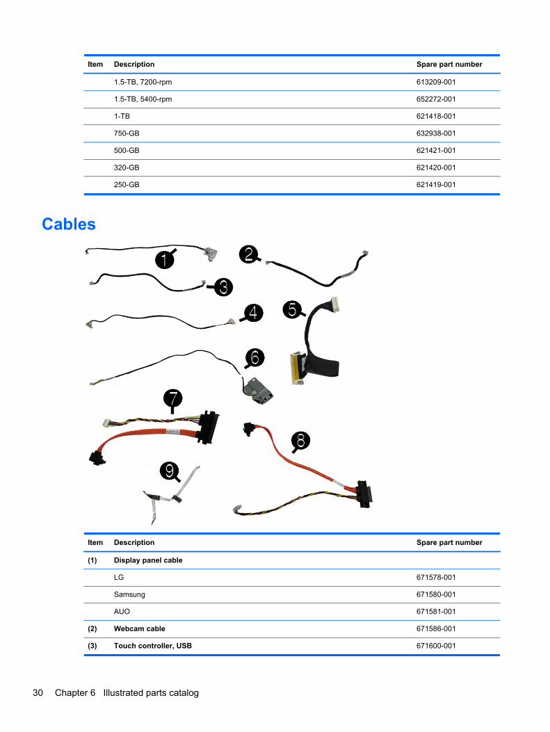
Cables
Item Description Spare part number
(1) Display panel cable
LG 671578-001
Samsung 671580-001
AUO 671581-001
(2) Webcam cable 671586-001
(3) Touch controller, USB 671600-001
30 Chapter 6 Illustrated parts catalog

Item Description Spare part number
(4) Converter 671599-001
(5) LVDS 671598-001
(6) Power button/LED 671597-001
(7) Hard drive 671595-001
(8) Optical drive 671596-001
(9) IR blaster cable (not illustrated) 671594-001
TV tuner connector, RF, NTSC, 40mm (not illustrated) 671593-001
TV tuner connector, RF, PAL, 40mm (not illustrated) 671601-001
Antenna for use with 2x2 WLAN module (not illustrated) 671559-001
Antenna for use with 1x1 WLAN module (not illustrated) 671560-001
Misc parts
Item Description Spare part number
(1) Fan 671582-001
(2) Speaker, left 671587-001
(3) Speaker, right 671588-001
(4) Thermal module (heat sink) for use with the graphics board 671562-001
(5) Thermal module (heat sink) for use with the processor 671548-001
Misc parts 31

Item Description Spare part number
Thermal pads (attach to middle frame under system board; not illustrated)
Thermal pad for use with the thermal module and processor 671549-001
Thermal pad for use with VCORE 671550-001
Thermal pad for use with VAXG 671551-001
Thermal pad for use with PCH/SB 671552-001
Thermal pad for use with memory modules 671553-001
Power supply, 180W, external (not illustrated) 613766-001
Mouse
USB, optical 596410-001
Wireless 625685-001
Hard drive cage (not illustrated) 671554-001
Hard drive rubber grommet (not illustrated) 663357-001
Optical drive dummy bezel (not illustrated) 671556-001
Optical drive bezel (not illustrated) 671557-001
Optical drive bracket (not illustrated) 671558-001
Label, rear I/O (NTSC/PAL) (not illustrated) 671592-001
Keyboards (not illustrated)NOTE: For a detailed list of keyboards and country codes, see Sequential part number listingon page 33.
Description Spare part number
USB, red 537924-xx1
USB 537924-xx1
USB, low cost 630886-xx1
Wireless 665719-xx1
USB, jade with Beats logo 655572-xx1
USB, jade 655571-xx1
32 Chapter 6 Illustrated parts catalog

Sequential part number listing
Spare partnumber
Description
537923-071 Keyboard, USB, red, for use in Spain
537924-001 Keyboard, USB for use in the United States
537924-031 Keyboard, USB for use in the United Kingdom
537924-041 Keyboard, USB for use in Germany
537924-051 Keyboard, USB for use in France
537924-061 Keyboard, USB for use in Italy
537924-071 Keyboard, USB for use in Spain
537924-081 Keyboard, USB for use in Denmark
537924-091 Keyboard, USB for use in Norway
537924-101 Keyboard, USB for use in Sweden
537924-111 Keyboard, USB for use in Switzerland
537924-121 Keyboard, USB for use in French Canada
537924-131 Keyboard, USB for use in Portugal
537924-141 Keyboard, USB for use in Turkey
537924-151 Keyboard, USB for use in Greece
537924-161 Keyboard, USB for use in Latin American Spanish
537924-171 Keyboard, USB for use in Saudi Arabia
537924-181 Keyboard, USB for use in Belgium
537924-201 Keyboard, USB for use in Brazil
537924-211 Keyboard, USB for use in Hungary
537924-221 Keyboard, USB for use in the Czech Republic
537924-231 Keyboard, USB for use in Slovakia
537924-241 Keyboard, USB for use in Poland
537924-251 Keyboard, USB for use in Russia
537924-261 Keyboard, USB for use in Bulgaria
537924-271 Keyboard, USB for use in Romania
537924-331 Keyboard, USB for use in the Netherlands
537924-351 Keyboard, USB for use in Finland
537924-B41 Keyboard, USB for use in BHCSY
537924-DE1 Keyboard, USB for use in French Arabic
537924-DH1 Keyboard, USB for use in Nordic
537924-L31 Keyboard, USB for use in International English
Sequential part number listing 33

Spare partnumber
Description
593233-001 Memory module, 2-GB (PC3-10600, 1333-MHz)
593234-001 Memory module, 4-GB (PC3-10600, 1333-MHz)
596410-001 Mouse, USB, optical
613209-001 Hard drive, 1.5-TB, 7200-rpm
613210-001 Hard drive, 2-TB, 7200-rpm
613766-001 Power supply, 180W, external
613990-001 HP Digital TV Tuner Mini PCIe Card (includes TV tuner and hardware kit; non-BFR)
616608-001 Hard drive, 2-TB, 5400-rpm
619238-001 HP SuperMulti DVD Writer Drive, 8x, LightScribe (does not include bezel)
619239-001 HP Slim Slot Blu-ray Combo Drive, 4x (does not include bezel)
621418-001 Hard drive, 1-TB
621419-001 Hard drive, 250-GB
621420-001 Hard drive, 320-GB
621421-001 Hard drive, 500-GB
621425-001 HP Digital TV Tuner Mini PCIe Card (includes TV tuner and hardware kit; BFR)
625685-001 Mouse, wireless
630886-DH1 Keyboard, USB, low cost for use in Nordic countries
632938-001 Hard drive, 750-GB
634906-001 802.11b/g/n (1x1) WLAN module
638411-001 Intel Core i3 processor, 2100 (3.1-GHz, 3-MB L3 cache)
638412-001 Intel Core i3 processor, 2120 (3.3-GHz, 3-MB L3 cache; not for use in Brazil)
638419-001 Intel Core i7 processor, 2600S (2.8-GHz, 8-MB L3 cache)
638420-001 Intel Core i5 processor, 2500S (2.7-GHz, 6-MB L3 cache)
640953-001 Intel Core i5 processor, 2400S (2.5-GHz, 6-MB L3 cache)
646800-001 Memory module, 2-GB (PC3-10600, 1333-MHz)
646801-001 Memory module, 4-GB (PC3-10600, 1333-MHz)
646808-001 Memory module, 1-GB (PC3-10600, 1333-MHz)
652272-001 Hard drive, 1.5-TB, 5400-rpm
652279-001 HP WLAN combo 802.11b/g/n + Bluetooth 2.1 card
654602-001 802.11b/g/n (2x2) WLAN card
655571-001 Keyboard, jade for use in the United States
655571-031 Keyboard, jade for use in the United Kingdom
655571-041 Keyboard, jade for use in Germany
655571-051 Keyboard, jade for use in France
34 Chapter 6 Illustrated parts catalog

Spare partnumber
Description
655571-061 Keyboard, jade for use in Italy
655571-071 Keyboard, jade for use in Spain
655571-081 Keyboard, jade for use in Denmark
655571-091 Keyboard, jade for use in Norway
655571-101 Keyboard, jade for use in Sweden
655571-111 Keyboard, jade for use in Switzerland
655571-121 Keyboard, jade for use in French Canada
655571-131 Keyboard, jade for use in Portugal
655571-141 Keyboard, jade for use in Turkey
655571-151 Keyboard, jade for use in Greece
655571-161 Keyboard, jade for use in Latin American Spanish
655571-171 Keyboard, jade for use in Saudi Arabia
655571-181 Keyboard, jade for use in Belgium
655571-201 Keyboard, jade for use in Brazil
655571-211 Keyboard, jade for use in Hungary
655571-221 Keyboard, jade for use in the Czech Republic
655571-231 Keyboard, jade for use in Slovakia
655571-241 Keyboard, jade for use in Poland
655571-251 Keyboard, jade for use in Russia
655571-261 Keyboard, jade for use in Bulgaria
655571-271 Keyboard, jade for use in Romania
655571-331 Keyboard, jade for use in the Netherlands
655571-351 Keyboard, jade for use in Finland
655571-B41 Keyboard, jade for use in BHCSY
655571-DE1 Keyboard, jade for use in French Arabic
655571-DH1 Keyboard, jade for use in Nordic
655571-L31 Keyboard, jade for use in International English
655572-001 Keyboard, jade with Beats logo for use in the United States
655572-031 Keyboard, jade with Beats logo for use in the United Kingdom
655572-041 Keyboard, jade with Beats logo for use in Germany
655572-051 Keyboard, jade with Beats logo for use in France
655572-061 Keyboard, jade with Beats logo for use in Italy
655572-071 Keyboard, jade with Beats logo for use in Spain
655572-081 Keyboard, jade with Beats logo for use in Denmark
Sequential part number listing 35

Spare partnumber
Description
655572-091 Keyboard, jade with Beats logo for use in Norway
655572-101 Keyboard, jade with Beats logo for use in Sweden
655572-111 Keyboard, jade with Beats logo for use in Switzerland
655572-121 Keyboard, jade with Beats logo for use in French Canada
655572-131 Keyboard, jade with Beats logo for use in Portugal
655572-141 Keyboard, jade with Beats logo for use in Turkey
655572-151 Keyboard, jade with Beats logo for use in Greece
655572-161 Keyboard, jade with Beats logo for use in Latin American Spanish
655572-171 Keyboard, jade with Beats logo for use in Saudi Arabia
655572-181 Keyboard, jade with Beats logo for use in Belgium
655572-201 Keyboard, jade with Beats logo for use in Brazil
655572-211 Keyboard, jade with Beats logo for use in Hungary
655572-221 Keyboard, jade with Beats logo for use in the Czech Republic
655572-231 Keyboard, jade with Beats logo for use in Slovakia
655572-241 Keyboard, jade with Beats logo for use in Poland
655572-251 Keyboard, jade with Beats logo for use in Russia
655572-261 Keyboard, jade with Beats logo for use in Bulgaria
655572-271 Keyboard, jade with Beats logo for use in Romania
655572-331 Keyboard, jade with Beats logo for use in the Netherlands
655572-351 Keyboard, jade with Beats logo for use in Finland
655572-B41 Keyboard, jade with Beats logo for use in BHCSY
655572-DE1 Keyboard, jade with Beats logo for use in French Arabic
655572-DH1 Keyboard, jade with Beats logo for use in Nordic
655572-L31 Keyboard, jade with Beats logo for use in International English
655970-001 Intel Core i3 processor, 2105 (3.1-GHz, 3-MB L3 cache)
655971-001 Intel Pentium Dual-Core processor, G620 (2.6-GHz, 3-MB L3 cache)
655972-001 Intel Pentium Dual-Core processor, G840 (2.8-GHz, 3-MB L3 cache
655973-001 Intel Pentium Dual-Core processor, G850 (2.9-GHz, 3-MB L3 cache)
657959-001 HP SuperMulti DVD Writer Drive, 8x, non-LightScribe (does not include bezel)
663357-001 Hard drive rubber grommet
665719-001 Keyboard, wireless for use in the United States
665719-031 Keyboard, wireless for use in the United Kingdom
665719-041 Keyboard, wireless for use in Germany
665719-051 Keyboard, wireless for use in France
36 Chapter 6 Illustrated parts catalog

Spare partnumber
Description
665719-061 Keyboard, wireless for use in Italy
665719-071 Keyboard, wireless for use in Spain
665719-081 Keyboard, wireless for use in Denmark
665719-091 Keyboard, wireless for use in Norway
665719-101 Keyboard, wireless for use in Sweden
665719-111 Keyboard, wireless for use in Switzerland
665719-121 Keyboard, wireless for use in French Canada
665719-131 Keyboard, wireless for use in Portugal
665719-141 Keyboard, wireless for use in Turkey
665719-151 Keyboard, wireless for use in Greece
665719-161 Keyboard, wireless for use in Latin American Spanish
665719-171 Keyboard, wireless for use in Saudi Arabia
665719-181 Keyboard, wireless for use in Belgium
665719-201 Keyboard, wireless for use in Brazil
665719-211 Keyboard, wireless for use in Hungary
665719-221 Keyboard, wireless for use in the Czech Republic
665719-231 Keyboard, wireless for use in Slovakia
665719-241 Keyboard, wireless for use in Poland
665719-251 Keyboard, wireless for use in Russia
665719-261 Keyboard, wireless for use in Bulgaria
665719-271 Keyboard, wireless for use in Romania
665719-331 Keyboard, wireless for use in the Netherlands
665719-351 Keyboard, wireless for use in Finland
665719-B41 Keyboard, wireless for use in BHCSY
665719-DE1 Keyboard, wireless for use in French Arabic
665719-DH1 Keyboard, wireless for use in Nordic
665719-L31 Keyboard, wireless for use in International English
671547-001 System board
671548-001 Thermal module (heat sink) for use with the processor
671549-001 Thermal pad for use with the thermal module and processor
671550-001 Thermal pad for use with VCORE
671551-001 Thermal pad for use with VAXG
671552-001 Thermal pad for use with PCH/SB
671553-001 Thermal pad for use with memory modules
Sequential part number listing 37

Spare partnumber
Description
671554-001 Hard drive cage
671555-001 HP SuperMulti DVD Writer Drive, 8x, LightScribe (includes bezel)
671556-001 Optical drive dummy bezel
671557-001 Optical drive bezel
671558-001 Optical drive bracket
671559-001 Antenna for use with 2x2 WLAN module
671560-001 Antenna for use with 1x1 WLAN module
671561-001 AMD Radeon HD 6450A 1GB DDR3 MXM 3.0A (includes bracket; not available in the Americas region)
671562-001 Thermal module (heat sink) for use with the graphics board
671563-001 AMD Radeon HD 6450A 1GB DDR3 MXM 3.0A (includes bracket; not available in the Americas region)
671564-001 NVIDIA GeForce GT 5xx 1GB DDR3 MXM 3.0A (includes bracket; not available in the Americas region)
671565-001 NVIDIA GeForce GT 5xx 2GB DDR3 MXM 3.0A (includes bracket; not available in the Americas region)
671566-001 HP TV Tuner SW DVB-T Mini Card (for use in EMEA)
671569-001 Converter
671570-001 Touch controller board
671571-001 Display panel, LGD (21.5-inch, touch screen, includes bezel)
671573-001 Display panel, Samsung (21.5-inch, touch screen, includes bezel)
671574-001 Display panel, AUO (21.5-inch, touch screen, includes bezel)
671578-001 Display panel cable - LG
671580-001 Display panel cable - Samsung
671581-001 Display panel cable - AUO
671582-001 Fan
671583-001 Webcam module
671585-001 Webcam lens cover
671586-001 Webcam cable
671587-001 Speaker, left
671588-001 Speaker, right
671589-001 Rear cover
671590-001 Front bezel
671591-001 Stand
671592-001 Label, rear I/O (NTSC/PAL)
671593-001 TV tuner connector, RF, NTSC, 40mm
671594-001 IR blaster cable
671595-001 Hard drive cable
38 Chapter 6 Illustrated parts catalog

Spare partnumber
Description
671596-001 Optical drive cable
671597-001 Power button/LED cable
671598-001 LVDS cable
671599-001 Converter cable
671600-001 Touch controller cable
671601-001 TV tuner, RF, PAL, 40mm
Sequential part number listing 39

7 Removal and Replacement ProceduresAll-in One (AIO) Chassis
The following sections provide information about disassembling various components of the computer.
Preparing to Disassemble the ComputerTo avoid injury and equipment damage, always complete the following steps in order, when openingthe HP Pro All-in-One.
1. Remove all media (CD, DVD, etc.) from the computer.
2. Shut down the computer.
3. After the system has completely shut down, disconnect the power adapter from the back of theHP Pro All-in-One.
4. Disconnect all other attached cables from the back of the computer.
5. Place the computer face down on a soft flat surface. HP recommends that you set down ablanket, towel, or other soft cloth to protect the screen surface from scratches or other damage.
WARNING! Beware of sharp edges inside the chassis.
40 Chapter 7 Removal and Replacement Procedures All-in One (AIO) Chassis

Rear Cover
Description Spare part number
Rear cover 671589-001
Remove the one main rear cover to access internal components
To remove the rear cover:
1. Prepare the computer for disassembly (see Preparing to Disassemble the Computeron page 40).
2. Open the VESA cover (1), and then loosen the 2 captive Phillips screws (2) that secure thecover to the computer.
NOTE: Some models may include a 3rd screw under the VESA cover.
Figure 7-1 Removing the rear cover
3. Lift the cover off the computer
To replace the rear cover, reverse the removal procedures.
Rear Cover 41

Stand
Description Spare part number
Stand 671591-001
The stand is secured with 8 screws.
To remove the stand:
1. Prepare the computer for disassembly (see Preparing to Disassemble the Computeron page 40).
2. Remove the rear cover (see Rear Cover on page 41).
3. To keep the stand from binding the screws, position the computer with the front facing downwardand the stand not touching the surface.
4. Remove the 8 Phillips screws (4 from each side) (1) that secure the stand to the computer.
5. Pull the stand down slightly, and then lift it off the computer (2).
Figure 7-2 Removing the stand
To replace the stand, reverse the removal procedures.
42 Chapter 7 Removal and Replacement Procedures All-in One (AIO) Chassis

Memory CoverTo remove the memory cover:
1. Prepare the computer for disassembly (see Preparing to Disassemble the Computeron page 40).
2. Remove the rear cover (see Rear Cover on page 41).
3. LIft the memory cover straight up and off the computer.
Figure 7-3 Removing the memory cover
Remove the memory cover to gain access to the following:
(1): Memory modules
(2): RTC battery
Memory Cover 43

(3): CMOS header/jumper
Figure 7-4 Memory cover components
A jumper settings table is printed on the sheet metal to the left of the memory cover.
Table 7-1 Jumper settings
2 4 Clear CMOS
4 6 Normal
1 3 Clear Password
3 5 Normal
The following table shows pin number locations for the header.
Table 7-2 Pin numbers
1 3 5
2 4 6
To replace the memory cover, reverse the removal procedures.
44 Chapter 7 Removal and Replacement Procedures All-in One (AIO) Chassis
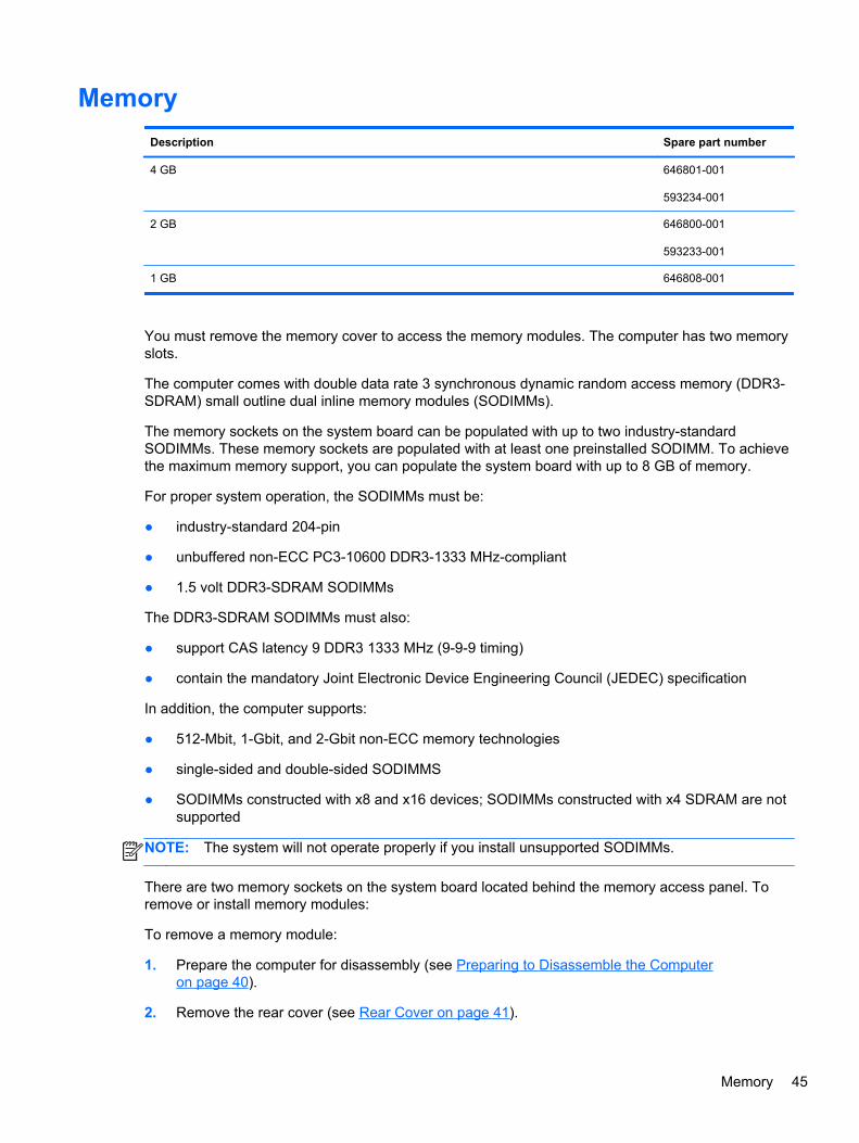
Memory
Description Spare part number
4 GB 646801-001
593234-001
2 GB 646800-001
593233-001
1 GB 646808-001
You must remove the memory cover to access the memory modules. The computer has two memoryslots.
The computer comes with double data rate 3 synchronous dynamic random access memory (DDR3-SDRAM) small outline dual inline memory modules (SODIMMs).
The memory sockets on the system board can be populated with up to two industry-standardSODIMMs. These memory sockets are populated with at least one preinstalled SODIMM. To achievethe maximum memory support, you can populate the system board with up to 8 GB of memory.
For proper system operation, the SODIMMs must be:
● industry-standard 204-pin
● unbuffered non-ECC PC3-10600 DDR3-1333 MHz-compliant
● 1.5 volt DDR3-SDRAM SODIMMs
The DDR3-SDRAM SODIMMs must also:
● support CAS latency 9 DDR3 1333 MHz (9-9-9 timing)
● contain the mandatory Joint Electronic Device Engineering Council (JEDEC) specification
In addition, the computer supports:
● 512-Mbit, 1-Gbit, and 2-Gbit non-ECC memory technologies
● single-sided and double-sided SODIMMS
● SODIMMs constructed with x8 and x16 devices; SODIMMs constructed with x4 SDRAM are notsupported
NOTE: The system will not operate properly if you install unsupported SODIMMs.
There are two memory sockets on the system board located behind the memory access panel. Toremove or install memory modules:
To remove a memory module:
1. Prepare the computer for disassembly (see Preparing to Disassemble the Computeron page 40).
2. Remove the rear cover (see Rear Cover on page 41).
Memory 45

3. Remove the memory cover (see Memory Cover on page 43).
4. To remove a memory module, press outward on the two latches on each side of the SODIMM(1), allow the module to lift up to about a 45-degree angle, and then pull the SODIMM out of thesocket (2).
Figure 7-5 Removing a memory module
The computer automatically recognizes the additional memory when you turn on the computer.
46 Chapter 7 Removal and Replacement Procedures All-in One (AIO) Chassis

Optical Drive
Description Spare part number
HP SuperMulti DVD Writer Drive, 8x, LightScribe (includes bezel) 671555-001
HP SuperMulti DVD Writer Drive, 8x, LightScribe (does not include bezel) 619238-001
HP SuperMulti DVD Writer Drive, 8x, non-LightScribe (does not include bezel) 657959-001
HP Slim Slot Blu-ray Combo Drive, 4x (does not include bezel) 619239-001
The optical drive is located on the left side of the computer (viewed from behind) under the inverterboard. It is secured with one screw.
Figure 7-6 Optical drive location
To remove the optical drive:
1. Prepare the computer for disassembly (see Preparing to Disassemble the Computeron page 40).
2. Remove the rear cover (see Rear Cover on page 41).
3. Loosen the Phillips screw (1) that secures the drive to the computer.
Optical Drive 47

4. Insert a screwdriver into the slot next to the drive bracket (2) and push the drive out of the bay,and then slide the drive out of the computer (3).
Figure 7-7 Removing the optical drive
5. If you need to remove the drive bracket from the drive, remove the two Torx screws (1) thatsecure the bracket to the drive, and then remove the bracket from the drive (2).
NOTE: Optical drive spare part kits do not include replacement brackets. Reuse the existingbracket.
Figure 7-8 Removing the optical drive bracket
To install an optical drive, reverse the removal procedures.
48 Chapter 7 Removal and Replacement Procedures All-in One (AIO) Chassis

Hard Drive
Description Spare part number
2-TB, 7200-rpm 613210-001
2-TB, 5400-rpm 616608-001
1.5-TB, 7200-rpm 613209-001
1.5-TB, 5400-rpm 652272-001
1-TB 621418-001
750-GB 632938-001
500-GB 621421-001
320-GB 621420-001
250-GB 621419-001
The hard drive is located on the left side of the computer (viewed from behind). The drive is securedwith one captive screw and is housed in a removable cage.
Figure 7-9 Hard drive location
1. Prepare the computer for disassembly (see Preparing to Disassemble the Computeron page 40).
2. Loosen the captive Phillips screw that secures the drive to the computer (1).
Hard Drive 49

3. Grasp the handle on top of the hard drive cage and slide the cage toward the outer edge of thecomputer (2), then lift the cage out of the computer (3).
Figure 7-10 Removing the hard drive cage
4. Remove the four Phillips mounting screws (1) that secure the drive to the cage. Do not removethe blue rubber grommets behind each screw. They must stay attached to the cage wheninstalling a new hard drive.
50 Chapter 7 Removal and Replacement Procedures All-in One (AIO) Chassis

5. Slide the hard drive out of the cage (2).
Figure 7-11 Removing the hard drive from the cage
NOTE: Be sure to correctly install the rubber grommets in the HDD cage. Incorrect installation canresult in hard drive installation problems.
To replace the hard drive, reverse the removal procedures.
Hard Drive 51

Converter Board
Description Spare part number
Converter board 671569-001
Converter cable 671599-001
The converter board is located on the left side of the computer. It is secured with 2 screws and has 2connectors.
Figure 7-12 converter board location
The backlight cable differs depending on the display panel vendor.
All display panel use the same converter board. You must properly set the jumper on the converterboard based on the vendor that produced the display panel.
CAUTION: Failure to properly set the converter board jumper can result in damage to the converterboard.
See the following image for display panel jumper settings. This information is also printed on thecomputer next to the converter board.
52 Chapter 7 Removal and Replacement Procedures All-in One (AIO) Chassis

Figure 7-13 Converter board jumper settings
To remove the converter board:
1. Prepare the computer for disassembly (see Preparing to Disassemble the Computeron page 40).
2. Remove the rear cover (see Rear Cover on page 41).
3. Disconnect the 2 cables from the board (1).
NOTE: Be careful not to damage the cables when disconnecting them from the board. Do notpull on the wires.
4. Remove the 2 Torx screws (2) that secure the board to the computer.
Figure 7-14 Removing the converter board
5. Lift the converter board from the computer.
To install the converter board, reverse the removal procedures.
Converter Board 53

Touch Controller Board
Description Spare part number
Touch controller board 671600-001
The touch controller board is located on the left side of the computer above the inverter board. It issecured with 1 screw and has 3 connectors.
Figure 7-15 Touch controller board location
To remove the touch screen board:
1. Prepare the computer for disassembly (see Preparing to Disassemble the Computeron page 40).
2. Remove the rear cover (see Rear Cover on page 41).
3. Disconnect the 3 cables from the board.
NOTE: The touch camera and FFC cables are marked with one dot and two dots to indicatethe camera position. Be sure to install the cables in the correct order – the cable with one dotconnects to the left side of the card; the cable with two dots connects to the right side of thecard.
54 Chapter 7 Removal and Replacement Procedures All-in One (AIO) Chassis

4. Remove the Torx screw that secures the board to the computer.
Figure 7-16 Removing the touch controller board
5. Lift the touch controller board from the computer.
To install the touch controller board, reverse the removal procedures.
Touch Controller Board 55

Webcam Module
Description Spare part number
Webcam module 671583-001
Webcam lens cover 671585-001
Webcam cable 671586-001
The webcam module is located at the top of the computer. It has one connector and is housed in abracket. The assembly is secured to the computer with 1 screw. The module is secured to the bracketwith 2 screws.
Figure 7-17 Webcam module location
To remove the webcam module:
1. Prepare the computer for disassembly (see Preparing to Disassemble the Computeron page 40).
2. Remove the rear cover (see Rear Cover on page 41).
56 Chapter 7 Removal and Replacement Procedures All-in One (AIO) Chassis

3. Remove the Torx screw (1) that secures the module to the computer, and lift the module fromthe computer as far as the cable allows (2).
Figure 7-18 Removing the webcam module assembly
4. Disconnect the cable from the module.
Figure 7-19 Disconnecting the webcam cable
5. Remove the two screws (1) that secure the module to the bracket, and then separate the modulefrom the bracket (2).
Figure 7-20 Removing the webcam module from the bracket
To install a webcam module, reverse the removal procedures.
Webcam Module 57

Speakers
Description Spare part number
Speaker, left 671587-001
Speaker, right 671588-001
The speakers are located at the bottom of the computer. Two separate speakers are each secured bytwo screws. The speakers are connected together by a cable and have one cable that routes to thesystem board connector.
Figure 7-21 Speaker location
To remove the speakers:
1. Prepare the computer for disassembly (see Preparing to Disassemble the Computeron page 40).
2. Remove the rear cover (see Rear Cover on page 41).
3. Remove two Phillips screws (1) that secure each speaker to the computer.
58 Chapter 7 Removal and Replacement Procedures All-in One (AIO) Chassis
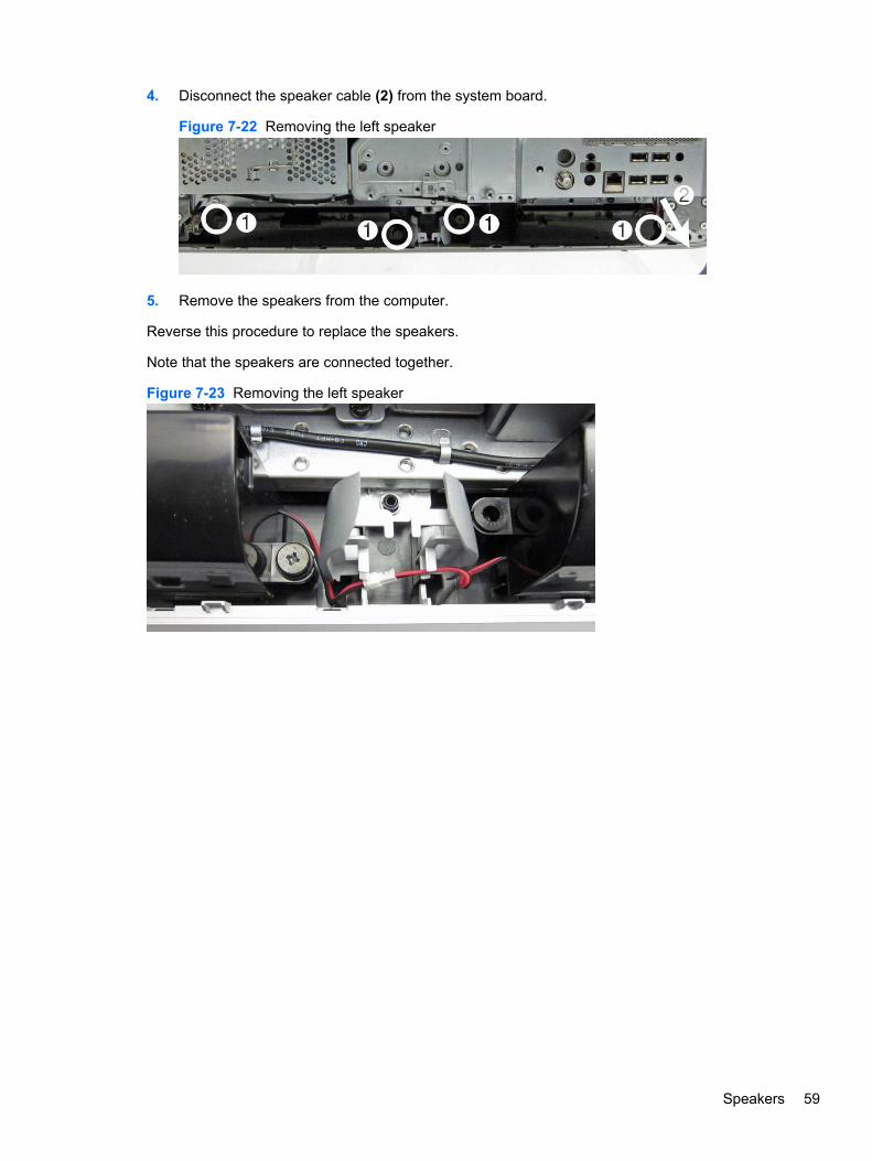
4. Disconnect the speaker cable (2) from the system board.
Figure 7-22 Removing the left speaker
5. Remove the speakers from the computer.
Reverse this procedure to replace the speakers.
Note that the speakers are connected together.
Figure 7-23 Removing the left speaker
Speakers 59

System Board CoverThe system board cover protects the system board. It is secured with four screws.
Figure 7-24 System board cover location
To remove the system board cover:
1. Prepare the computer for disassembly (see Preparing to Disassemble the Computeron page 40).
2. Remove the rear cover (see Rear Cover on page 41).
3. Remove the four Torx screws (1) that secure the cover to the computer.
60 Chapter 7 Removal and Replacement Procedures All-in One (AIO) Chassis

4. Lift the left side of the cover, and then rotate the cover up and off the computer (2).
Figure 7-25 Removing the system board cover
To install the system board cover, reverse the removal procedures.
System Board Cover 61

WLAN Module
Description Spare part number
802.11b/g/n (2x2) WLAN card 654602-001
HP WLAN combo 802.11b/g/n + Bluetooth 2.1 card 652279-001
802.11b/g/n (1x1) WLAN module 634906-001
The WLAN module is secured with 2 screws and has 1 connected antenna.
Figure 7-26 WLAN module location
To remove the WLAN module:
1. Prepare the computer for disassembly (see Preparing to Disassemble the Computeron page 40).
2. Remove the rear cover (see Rear Cover on page 41).
3. Remove the system board cover (see System Board Cover on page 60).
4. Disconnect the antenna cable from the module (1).
62 Chapter 7 Removal and Replacement Procedures All-in One (AIO) Chassis
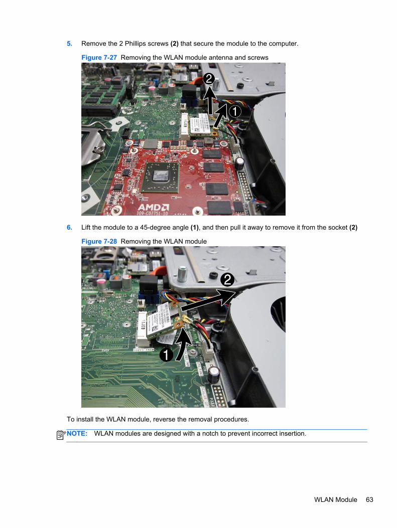
5. Remove the 2 Phillips screws (2) that secure the module to the computer.
Figure 7-27 Removing the WLAN module antenna and screws
6. Lift the module to a 45-degree angle (1), and then pull it away to remove it from the socket (2)
Figure 7-28 Removing the WLAN module
To install the WLAN module, reverse the removal procedures.
NOTE: WLAN modules are designed with a notch to prevent incorrect insertion.
WLAN Module 63

TV Tuner Module
Description Spare part number
HP Digital TV Tuner Mini PCIe Card (includes TV tuner and hardware kit; non-BFR) 613990-001
HP Digital TV Tuner Mini PCIe Card (includes TV tuner and hardware kit; BFR) 621425-001
HP TV Tuner SW DVB-T Mini Card for use in EMEA 671566-001
The TV tuner module is secured with 2 screws and has 1 connected antenna.
Figure 7-29 TV tuner module location
To remove the TV tuner module:
1. Prepare the computer for disassembly (see Preparing to Disassemble the Computeron page 40).
2. Remove the rear cover (see Rear Cover on page 41).
3. Remove the system board cover (see System Board Cover on page 60).
4. Disconnect the antenna cable from the module (1).
64 Chapter 7 Removal and Replacement Procedures All-in One (AIO) Chassis

5. Remove the 2 Phillips screws (2) that secure the module to the computer.
Figure 7-30 Removing the TV tuner module antenna and screws
6. Lift the module to a 45-degree angle (1), and then pull it away to remove it from the socket (2)
Figure 7-31 Removing the TV tuner module
To install the TV tuner module, reverse the removal procedures.
NOTE: TV tuner modules are designed with a notch to prevent incorrect insertion.
TV Tuner Module 65

Heat sinks (Thermal Modules)The computer has a heat sink for the processor (1) and a heat sink for the discrete graphics card(select models) (2). Each heat sink is secured with 4 captive screws and 1 non-captive screw. Youmust remove the processor heat sink before you can remove the graphics heat sink.
Figure 7-32 Heat sink location
To remove the heat sinks:
1. Prepare the computer for disassembly (see Preparing to Disassemble the Computeron page 40).
2. Remove the rear cover (see Rear Cover on page 41).
3. Remove the system board cover (see System Board Cover on page 60).
4. Loosen the 4 captive Torx screws (1) that secure the processor heat sink to the computer.
5. Remove the 1 non-captive Torx screw (2) that secures the heat sink to the computer.
66 Chapter 7 Removal and Replacement Procedures All-in One (AIO) Chassis

6. Lift the processor heat sink off the computer (3).
Figure 7-33 Removing the processor heat sink
7. If you need to remove the graphics heat sink, loosen the 4 captive Torx screws (1) that securethe heat sink to the computer.
8. Remove the 1 non-captive Torx screw (2) that secures the heat sink to the computer.
9. Lift the graphics heat sink off the computer (3).
Figure 7-34 Removing the graphics heat sink
To install the heat sinks, reverse the removal procedures.
Heat sinks (Thermal Modules) 67

Processor
Description Spare part number
Intel Core i7 processors
2600S (2.7 GHz, 8-MB L3 cache; not for Brazil) 638419-001
Intel Core i5 processors
2500S (2.7 GHz, 6-MB L3 cache) 638420-001
2400S (3.1-GHz, 6-MB L3 cache) 640953-001
Intel Core i3 processors
2120 (3.3 GHz, 3-MB L3 cache) 638412-001
2105 (3.1 GHz, 3-MB L3 cache) 655970-001
2100 (3.1 GHz, 3-MB L3 cache) 638411-001
Intel Pentium Dual-Core processors
G850 (2.9-GHz, 3-MB L3 cache) 655973-001
G840 (2.8-GHz, 3-MB L3 cache) 655972-001
G620 (2.6-GHz, 3-MB L3 cache) 655971-001
1. Prepare the computer for disassembly (see Preparing to Disassemble the Computeron page 40).
2. Remove the rear cover (see Rear Cover on page 41).
3. Remove the system board cover (see System Board Cover on page 60).
4. Remove the processor heat sink (see Heat sinks (Thermal Modules) on page 66).
68 Chapter 7 Removal and Replacement Procedures All-in One (AIO) Chassis

5. Rotate the locking lever to its full open position (1), raise and rotate the microprocessor retainerto its full open position (2), and then carefully lift the processor from the socket (3).
CAUTION: Do NOT handle the pins in the processor socket. These pins are very fragile andhandling them could cause irreparable damage. Once pins are damaged it may be necessary toreplace the system board.
CAUTION: The heat sink must be installed within 24 hours of installing the processor toprevent damage to the processor’s solder connections.
Figure 7-35 Removing an Intel processor
To install a new processor:
1. Place the processor in its socket.
2. Close the retainer.
3. Secure the locking lever.
If reusing the existing heat sink, go to step 4.
If using a new heat sink, go to step 7.
4. If reusing the existing heat sink, clean the bottom of the heat sink.
5. Apply the thermal material provided in the spares kit to the top of the processor and install theheat sink atop the processor.
6. Go to step 8.
7. If using a new heat sink, remove the protective covering from the bottom of the heat sink andplace it in position atop the processor.
8. Secure the heat sink to the system board and system board tray with the screws.
CAUTION: Heat sink retaining screws should be tightened in diagonally opposite pairs (as inan X) to evenly seat the heat sink on the processor. This is especially important as the pins onthe socket are very fragile and any damage to them may require replacing the system board.
Processor 69

NOTE: After installing a new processor onto the system board, always update the systemROM to ensure that the latest version of the BIOS is being used on the computer. The latestsystem ROM BIOS can be found on the Web at: http:\\h18000.www1.hp.com/support/files.
Graphics CardNOTE: The Americas region offers only integrated graphics; a discrete graphics option is notavailable.
Description Spare part number
AMD Radeon HD 6450A 1GB DDR3 MXM 3.0A (includes bracket; not available in the Americasregion)
671561-001
AMD Radeon HD 6550A 2GB DDR3 MXM 3.0A (includes bracket; not available in the Americasregion)
671563-001
NVIDIA GeForce GT 5xx 1GB DDR3 MXM 3.0A (includes bracket; not available in the Americasregion)
671564-001
NVIDIA GeForce GT 5xx 2GB DDR3 MXM 3.0A (includes bracket; not available in the Americasregion)
671565-001
The graphics card is located under its own heat sink on the upper left of the system board. To removeit, you have to first remove the processor heat sink, and then the graphics card heat sink.
Figure 7-36 Graphics card location
To remove the graphics card:
1. Prepare the computer for disassembly (see Preparing to Disassemble the Computeron page 40).
2. Remove the rear cover (see Rear Cover on page 41).
3. Remove the system board cover (see System Board Cover on page 60).
4. Remove the heat sinks (see Heat sinks (Thermal Modules) on page 66).
70 Chapter 7 Removal and Replacement Procedures All-in One (AIO) Chassis

5. Remove the 2 Phillips screws that secure the card to the system board.
Figure 7-37 Removing the graphics card
6. Lift the module to a 45-degree angle (1) , and then pull it away to remove it from the socket (2).
Figure 7-38 Removing the graphics card
To install the graphics card, reverse the removal procedures.
Graphics Card 71

Fan
Description Spare part number
Fan 671582-001
The fan is located in the middle of the computer. It is secured with 3 screws.
Figure 7-39 Fan location
To remove the fan:
1. Prepare the computer for disassembly (see Preparing to Disassemble the Computeron page 40).
2. Remove the rear cover (see Rear Cover on page 41).
3. Remove the system board cover (see System Board Cover on page 60).
4. Remove the 3 Torx screws (1) that secure the fan to the computer.
5. Disconnect the fan cable (2) from the system board connector.
72 Chapter 7 Removal and Replacement Procedures All-in One (AIO) Chassis
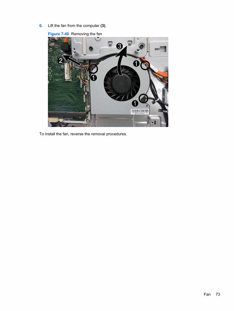
6. Lift the fan from the computer (3).
Figure 7-40 Removing the fan
To install the fan, reverse the removal procedures.
Fan 73

VESA Cover with Kensington Lock BracketThe square, metal VESA cover is located in the middle, bottom of the computer. It is secured with 4screws. The Kensington Lock bracket is permanently mounted to the VESA cover.
Figure 7-41 VESA cover with Kensington Lock bracket location
To remove the VESA cover:
1. Prepare the computer for disassembly (see Preparing to Disassemble the Computeron page 40).
2. Remove the rear cover (see Rear Cover on page 41).
3. Remove the system board cover (see System Board Cover on page 60).
74 Chapter 7 Removal and Replacement Procedures All-in One (AIO) Chassis

4. Remove the 4 Torx screws (1) that secure the cable cover to the computer.
NOTE: The Kensington lock bracket (2) is connected to the VESA cover. You cannot removethe bracket from the cover. You must replace the entire VESA cover to replace the KensingtonLock bracket.
Figure 7-42 Removing the VESA cover screws
5. Lift the cover off the computer.
Figure 7-43 Removing the VESA cover
To replace the VESA cover, reverse the removal procedures.
VESA Cover with Kensington Lock Bracket 75

Optical and Hard Drive Cables and Connector
Description Spare part number
Optical drive connector cable 671596-001
Hard drive connector cable 671595-001
Both the optical drive connector and the hard drive connector are secured with two screws and havetwo cables that connect to the system board. the cables are located under the square cover.
To remove the drive connectors:
1. Prepare the computer for disassembly (see Preparing to Disassemble the Computeron page 40).
2. Remove the rear cover (see Rear Cover on page 41).
3. Remove the optical drive (see Optical Drive on page 47).
4. Remove the hard drive (see Hard Drive on page 49).
5. Remove the square cover (see VESA Cover with Kensington Lock Bracket on page 74).
6. For the drive you want to remove, disconnect the power (1) and data (2) cables from the systemboard.
NOTE: Be careful not to damage the cables when disconnecting them from the board. Do notpull on the wires.
7. Remove the cables from the metal clips built into the computer (3).
8. Remove 2 Torx screws that secure the drive connector (4) to the computer.
76 Chapter 7 Removal and Replacement Procedures All-in One (AIO) Chassis
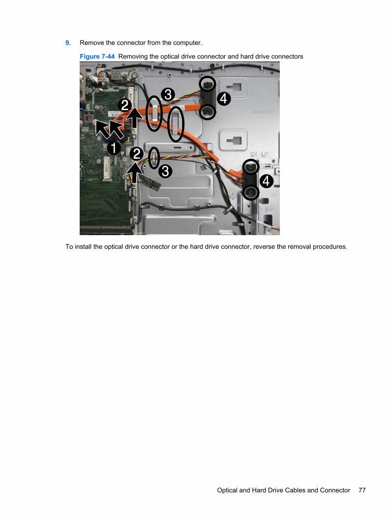
9. Remove the connector from the computer.
Figure 7-44 Removing the optical drive connector and hard drive connectors
To install the optical drive connector or the hard drive connector, reverse the removal procedures.
Optical and Hard Drive Cables and Connector 77
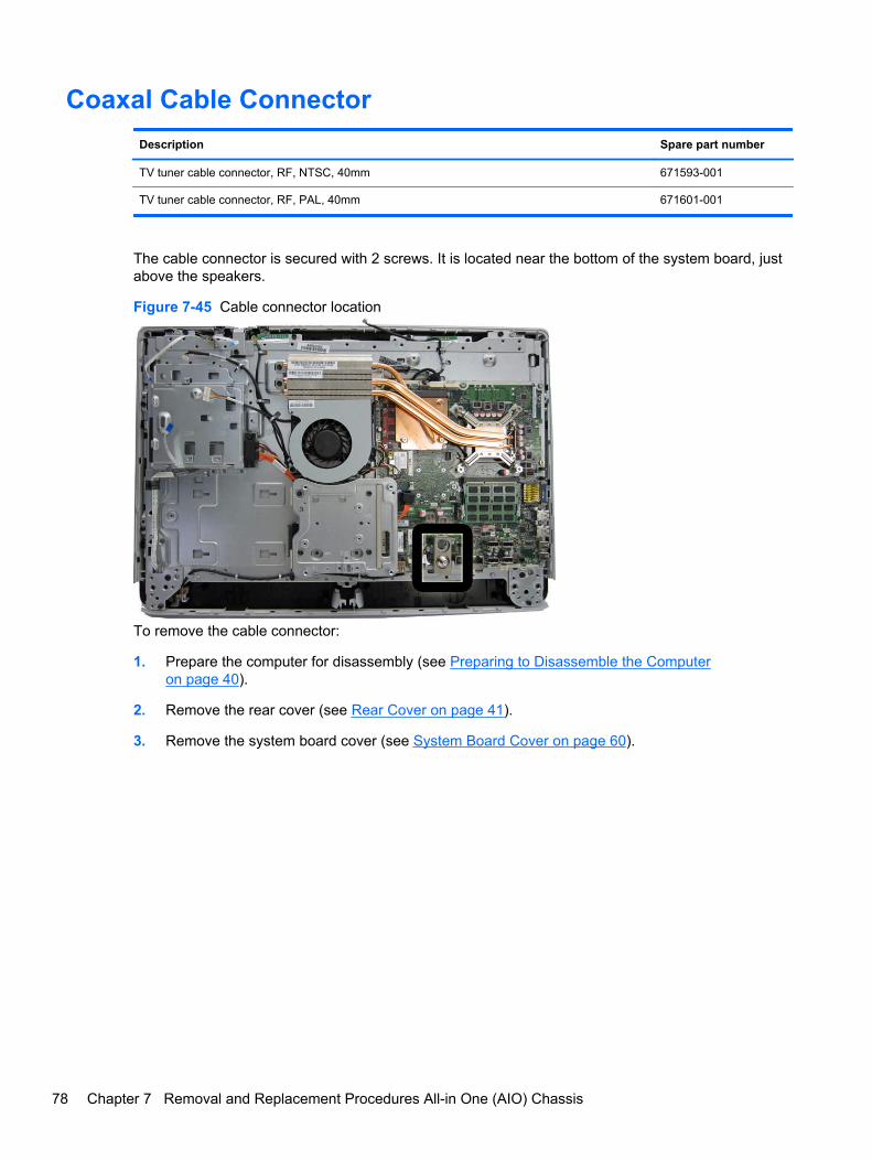
Coaxal Cable Connector
Description Spare part number
TV tuner cable connector, RF, NTSC, 40mm 671593-001
TV tuner cable connector, RF, PAL, 40mm 671601-001
The cable connector is secured with 2 screws. It is located near the bottom of the system board, justabove the speakers.
Figure 7-45 Cable connector location
To remove the cable connector:
1. Prepare the computer for disassembly (see Preparing to Disassemble the Computeron page 40).
2. Remove the rear cover (see Rear Cover on page 41).
3. Remove the system board cover (see System Board Cover on page 60).
78 Chapter 7 Removal and Replacement Procedures All-in One (AIO) Chassis

4. Remove the 2 Torx screws that secure the connector to the computer, and then lift the connectoroff the computer.
Figure 7-46 Removing the cable connector
To install the cable connector, reverse the removal procedures.
Coaxal Cable Connector 79

System Board
Description Spare part number
System board 671547-001
The system board is secured with nine screws.
Figure 7-47 System board location
To remove the system board:
1. Prepare the computer for disassembly (see Preparing to Disassemble the Computeron page 40).
2. Remove the rear cover (see Rear Cover on page 41).
3. Remove the system board cover (see System Board Cover on page 60).
4. Remove the heat sinks (see Heat sinks (Thermal Modules) on page 66).
5. Remove the coaxal cable connector (see Coaxal Cable Connector on page 78).
6. Remove the memory module (see Memory on page 45).
7. Remove the WLAN module (see WLAN Module on page 62).
8. Remove the TV tuner module (see TV Tuner Module on page 64).
9. Disconnect all cables from the system board, noting their location for reinstallation.
80 Chapter 7 Removal and Replacement Procedures All-in One (AIO) Chassis

10. Remove the 9 Torx screws (circled in image) that secure the system board to the computer.
Figure 7-48 Removing the system board
11. Lift the system board straight up and out of the computer.
System Board 81

12. Use the following image to determine the locations for required thermal pads under the systemboard.
Figure 7-49 Thermal pad locations
To install the system board, reverse the removal procedures.
82 Chapter 7 Removal and Replacement Procedures All-in One (AIO) Chassis

Display Cable
Description Spare part number
Display cable (LVDS) 671598-001
The display cable is located near the top of the system board. You can select from two differentmethods to remove the display cable:
● Detach the middle frame screws, lift the middle frame, and reach under to disconnect the cable.
For more information about removing the middle frame, see Front Bezel and Display Panelon page 85.
● Remove the system board to disconnect the display cable from the display panel (shown in thefollowing procedure).
Figure 7-50 Display cable location
To remove the display cable:
1. Prepare the computer for disassembly (see Preparing to Disassemble the Computeron page 40).
2. Remove the rear cover (see Rear Cover on page 41).
3. Remove the optical drive (see Optical Drive on page 47).
4. Remove the system board cover (see System Board Cover on page 60).
5. Remove the heat sinks (see Heat sinks (Thermal Modules) on page 66).
6. Remove the coaxal cable connector (see Coaxal Cable Connector on page 78).
7. Remove the system board (see System Board on page 80).
8. Press the latches on each side of the cable connector (1) to disengage the cable from theconnector.
Display Cable 83

9. Put the cable from the connector (2) to remove it.
Figure 7-51 Removing the display cable
To install the display cable, reverse the removal procedures.
84 Chapter 7 Removal and Replacement Procedures All-in One (AIO) Chassis

Front Bezel and Display Panel
Description Spare part number
21.5-inch, LGD 671571-001
21.5-inch, Samsung 671573-001
21.5-inch, AUO 671574-001
Front bezel 671590-001
The front bezel is located on the front of the computer. You do not have to disassemble most internalcomponents to remove the front bezel. After lifting the main computer assembly from the bezel, thedisplay panel remains attached. This procedure demonstrates removing the front bezel and displaypanel while keeping as much of the computer assembled as possible.
NOTE: You must calibrate the display panel after replacement. For calibration procedures, seehttp://thesml.hp.com/results.htm?SID=5146296&MEID=DA800C0B-C65E-454F-A8B4-17895E54764A.
To remove the front bezel:
1. Prepare the computer for disassembly (see Preparing to Disassemble the Computeron page 40).
2. Remove the rear cover (see Rear Cover on page 41).
3. Remove the optical drive (see Optical Drive on page 47).
4. Remove the speakers (see Speakers on page 58).
5. Remove the webcam (see Webcam Module on page 56).
6. Disconnect the flat ribbon cables from the touch controller board.
7. Disconnect the flat ribbon cable from the display that connects from the converter board.
8. Disconnect the logo cable from the bottom of the system board (1) and remove the cable fromthe clips (2) in the computer.
Figure 7-52 Disconnecting the logo cable
Front Bezel and Display Panel 85

9. Remove the power switch assembly by removing the screw and setting it aside.
Figure 7-53 Removing the power switch assembly
10. Remove the 16 Torx screws that secure the bezel to the computer, as follows:
● Left: 2 screws
Figure 7-54 Removing the middle frame screws – left
86 Chapter 7 Removal and Replacement Procedures All-in One (AIO) Chassis

● Right: 2 screws
Figure 7-55 Removing the middle frame screws – right
● Top: 4 screws
Figure 7-56 Removing the middle frame screws – top
Front Bezel and Display Panel 87

● Bottom: 8 screws
Figure 7-57 Removing the middle frame screws – bottom
11. Disengage the tabs that secure the bezel to the computer, as follows.
● Left: 2 tabs
● Right: 2 tabs
Figure 7-58 Middle frame tabs
12. As far as the display cable allows, separate the computer assembly from the display/bezelassembly.
CAUTION: Be careful not to separate the computer and panel too far before disconnecting thedisplay cable.
88 Chapter 7 Removal and Replacement Procedures All-in One (AIO) Chassis

13. Disconnect the display cable from the display panel by pressing in to the side tabs and pullingthe cable from the connector.
Figure 7-59 Disconnecting the display cable from the display panel
14. Remove the four Torx screws (1) that secure the display panel to the front bezel.
15. Disengage the tabs (2) that secure the display panel to the bezel, as follows.
● Left: 3 tabs
● Right: 3 tabs
● Top: 2 tabs
Figure 7-60 Removing the display panel from the front bezel
16. Lift the display panel off the front bezel.
Front Bezel and Display Panel 89

17. Remove the brackets from the top and bottom of the display panel by removing the 2 Torxscrews from each bracket, and then lifting each bracket off the panel.
NOTE: Display panel bracket location varies by vendor. Brackets are located on the top andbottom, or on the left and right, depending on vendor. These images show brackets on the topand bottom of the display panel.
Figure 7-61 Removing the brackets from the display panel
Figure 7-62 Display panel bracket location
To install the front bezel and display panel, reverse the removal procedures.
You must calibrate the display after replacement. For calibration procedures, seehttp://thesml.hp.com/results.htm?SID=5146296&MEID=DA800C0B-C65E-454F-A8B4-17895E54764A.
90 Chapter 7 Removal and Replacement Procedures All-in One (AIO) Chassis

Cable RoutingUse the following image as a reference for proper cable routing.
Figure 7-63 Cable routing
Cable Routing 91
A Troubleshooting Without Diagnostics
This chapter provides information on how to identify and correct minor problems, such as diskettedrive, hard drive, optical drive, graphics, audio, memory, and software problems. If you encounterproblems with the computer, refer to the tables in this chapter for probable causes and recommendedsolutions.
Safety and ComfortWARNING! Misuse of the computer or failure to establish a safe and comfortable work environmentmay result in discomfort or serious injury. Refer to the Safety & Comfort Guide at http://www.hp.com/ergo for more information on choosing a workspace and creating a safe and comfortable workenvironment. For more information, refer to the Safety & Regulatory Information guide.
Before You Call for Technical SupportIf you are having problems with the computer, try the appropriate solutions below to try to isolate theexact problem before calling for technical support.
● Run the HP diagnostic tool.
● Run the hard drive self-test in Computer Setup.
● Check the Power LED on the front of the computer to see if it is flashing red. The flashing lightsare error codes that will help you diagnose the problem. Refer to Appendix A, POST ErrorMessages on page 131 for more information.
● If the screen is blank, plug the monitor into a different video port on the computer if one isavailable. Or, replace the monitor with a monitor that you know is functioning properly.
● If you are working on a network, plug another computer with a different cable into the networkconnection. There may be a problem with the network plug or cable.
● If you recently added new hardware, remove the hardware and see if the computer functionsproperly.
● If you recently installed new software, uninstall the software and see if the computer functionsproperly.
● Boot the computer to the Safe Mode to see if it will boot without all of the drivers loaded. Whenbooting the operating system, use “Last Known Configuration.”
● Refer to the comprehensive online technical support at http://www.hp.com/support.
● Refer to Helpful Hints on page 93 in this guide.
92 Appendix A Troubleshooting Without Diagnostics

To assist you in resolving problems online, HP Instant Support Professional Edition provides you withself-solve diagnostics. If you need to contact HP support, use HP Instant Support ProfessionalEdition's online chat feature. Access HP Instant Support Professional Edition at: http://www.hp.com/go/ispe.
Access the Business Support Center (BSC) at http://www.hp.com/go/bizsupport for the latest onlinesupport information, software and drivers, proactive notification, and worldwide community of peersand HP experts.
If it becomes necessary to call for technical assistance, be prepared to do the following to ensure thatyour service call is handled properly:
● Be in front of your computer when you call.
● Write down the computer serial number, product ID number, and monitor serial number beforecalling.
● Spend time troubleshooting the problem with the service technician.
● Remove any hardware that was recently added to your system.
● Remove any software that was recently installed.
● Restore the system from the Recovery Disc Set that you created or restore the system to itsoriginal factory condition in HP Backup and Recovery Manager.
CAUTION: Restoring the system will erase all data on the hard drive. Be sure to back up all datafiles before running the restore process.
NOTE: For sales information and warranty upgrades (Care Packs), call your local authorizedservice provider or dealer.
Helpful HintsIf you encounter problems with the computer, monitor, or software, see the following list of generalsuggestions before taking further action:
● Check that the computer and monitor are plugged into a working electrical outlet.
● Check that the voltage select switch (some models) is set to the appropriate voltage for yourregion (115V or 230V).
● Check that the computer is turned on and the green power light is on.
● Check that the monitor is turned on and the green monitor light is on.
● Check the Power LED on the front of the computer to see if it is flashing red. The flashing lightsare error codes that will help you diagnose the problem. Refer to Appendix A, POST ErrorMessages on page 131 for more information.
● Turn up the brightness and contrast controls of the monitor if the monitor is dim.
● Press and hold any key. If the system beeps, then the keyboard should be operating correctly.
● Check all cable connections for loose connections or incorrect connections.
● Wake the computer by pressing any key on the keyboard or pressing the power button. If thesystem remains in suspend mode, shut down the computer by pressing and holding the power
Helpful Hints 93

button for at least four seconds then press the power button again to restart the computer. If thesystem will not shut down, unplug the power cord, wait a few seconds, then plug it in again. Thecomputer will restart if it is set to power on automatically as soon as power is restored inComputer Setup. If it does not restart, press the power button to start the computer.
● Reconfigure the computer after installing a non-plug and play expansion board or other option.See Solving Hardware Installation Problems on page 116 for instructions.
● Be sure that all the needed device drivers have been installed. For example, if you are using aprinter, you need a driver for that model printer.
● Remove all bootable media (diskette, CD, or USB device) from the system before turning it on.
● If you have installed an operating system other than the factory-installed operating system,check to be sure that it is supported on the system.
● If the system has multiple video sources (embedded, PCI, or PCI-Express adapters) installed(embedded video on some models only) and a single monitor, the monitor must be plugged intothe monitor connector on the source selected as the primary VGA adapter. During boot, theother monitor connectors are disabled and if the monitor is connected into these ports, themonitor will not function. You can select which source will be the default VGA source inComputer Setup.
CAUTION: When the computer is plugged into an AC power source, there is always voltage appliedto the system board. You must disconnect the power cord from the power source before opening thecomputer to prevent system board or component damage.
94 Appendix A Troubleshooting Without Diagnostics

Solving General ProblemsYou may be able to easily resolve the general problems described in this section. If a problempersists and you are unable to resolve it yourself or if you feel uncomfortable about performing theoperation, contact an authorized dealer or reseller.
WARNING! When the computer is plugged into an AC power source, voltage is always applied tothe system board. To reduce the risk of personal injury from electrical shock and/or hot surfaces, besure to disconnect the power cord from the wall outlet and allow the internal system components tocool before touching.
Table A-1 Solving General Problems
Computer appears locked up and will not turn off when the power button is pressed.
Cause Solution
Software control of the power switch is not functional. 1. Press and hold the power button for at least fourseconds until the computer turns off.
2. Disconnect the power cord from the electrical outlet.
Computer will not respond to USB keyboard or mouse.
Cause Solution
Computer is in standby mode. To resume from standby mode, press the power button orpress any key.
CAUTION: When attempting to resume from standbymode, do not hold down the power button for more than fourseconds. Otherwise, the computer will shut down and youwill lose any unsaved data.
System has locked up. Restart computer.
Computer date and time display is incorrect.
Cause Solution
RTC (real-time clock) battery may need to be replaced.
NOTE: Connecting the computer to a live AC outletprolongs the life of the RTC battery.
First, reset the date and time under Control Panel(Computer Setup can also be used to update the RTC dateand time). If the problem persists, replace the RTC battery.See the Removal and Replacement section for instructionson installing a new battery, or contact an authorized dealer orreseller for RTC battery replacement.
Cursor will not move using the arrow keys on the keypad.
Cause Solution
The Num Lock key may be on. Press the Num Lock key. The Num Lock light should not beon if you want to use the arrow keys. The Num Lock key canbe disabled (or enabled) in Computer Setup.
Solving General Problems 95

There is no sound or sound volume is too low.
Cause Solution
System volume may be set low or muted. 1. Check the F10 BIOS settings to make sure the internalsystem speaker is not muted (this setting does notaffect the external speakers).
2. Make sure the external speakers are properlyconnected and powered on and that the speakers'volume control is set correctly.
3. Use the system volume control available in theoperating system to make sure the speakers are notmuted or to increase the volume.
Poor performance is experienced.
Cause Solution
Processor is hot. 1. Make sure airflow to the computer is not blocked. Leavea 10.2-cm (4-inch) clearance on all vented sides of thecomputer and above the monitor to permit the requiredairflow.
2. Make sure fans are connected and working properly(some fans only operate when needed).
3. Make sure the processor heat sink is installed properly.
Hard drive is full. Transfer data from the hard drive to create more space onthe hard drive.
Low on memory. Add more memory.
Hard drive fragmented. Defragment hard drive.
Program previously accessed did not release reservedmemory back to the system.
Restart the computer.
Virus resident on the hard drive. Run virus protection program.
Too many applications running. 1. Close unnecessary applications to free up memory.
2. Add more memory. Some applications run in thebackground and can be closed by right-clicking on theircorresponding icons in the task tray. To prevent theseapplications from launching at startup, go to Start >Run (Windows XP) or Start > All Programs >Accessories > Run (Windows Vista and 7) and typemsconfig. On the Startup tab of the SystemConfiguration Utility, clear applications that you do notwant to launch automatically.
Some software applications, especially games, are stressfulon the graphics subsystem
1. Lower the display resolution for the current applicationor consult the documentation that came with theapplication for suggestions on how to improveperformance by adjusting parameters in the application.
2. Add more memory.
3. Upgrade the graphics solution.
Cause unknown. Restart the computer.
96 Appendix A Troubleshooting Without Diagnostics
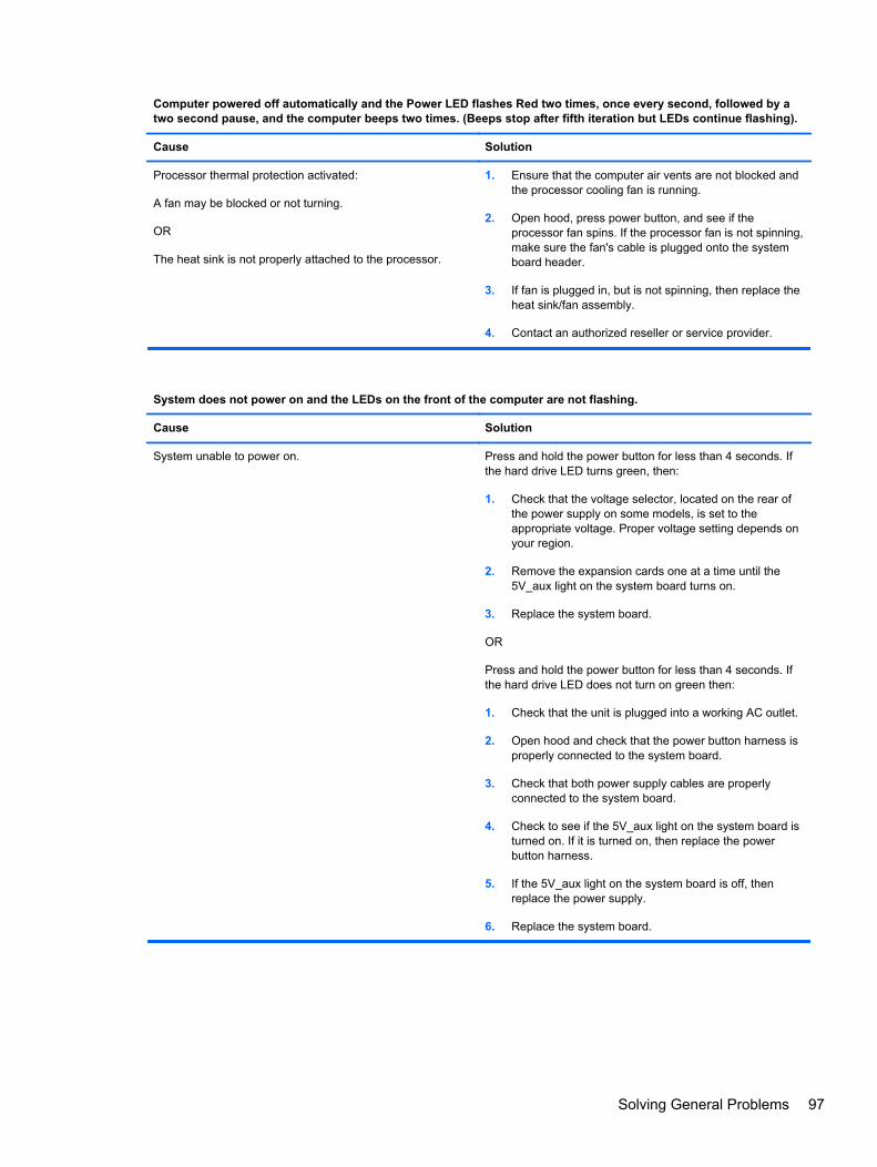
Computer powered off automatically and the Power LED flashes Red two times, once every second, followed by atwo second pause, and the computer beeps two times. (Beeps stop after fifth iteration but LEDs continue flashing).
Cause Solution
Processor thermal protection activated:
A fan may be blocked or not turning.
OR
The heat sink is not properly attached to the processor.
1. Ensure that the computer air vents are not blocked andthe processor cooling fan is running.
2. Open hood, press power button, and see if theprocessor fan spins. If the processor fan is not spinning,make sure the fan's cable is plugged onto the systemboard header.
3. If fan is plugged in, but is not spinning, then replace theheat sink/fan assembly.
4. Contact an authorized reseller or service provider.
System does not power on and the LEDs on the front of the computer are not flashing.
Cause Solution
System unable to power on. Press and hold the power button for less than 4 seconds. Ifthe hard drive LED turns green, then:
1. Check that the voltage selector, located on the rear ofthe power supply on some models, is set to theappropriate voltage. Proper voltage setting depends onyour region.
2. Remove the expansion cards one at a time until the5V_aux light on the system board turns on.
3. Replace the system board.
OR
Press and hold the power button for less than 4 seconds. Ifthe hard drive LED does not turn on green then:
1. Check that the unit is plugged into a working AC outlet.
2. Open hood and check that the power button harness isproperly connected to the system board.
3. Check that both power supply cables are properlyconnected to the system board.
4. Check to see if the 5V_aux light on the system board isturned on. If it is turned on, then replace the powerbutton harness.
5. If the 5V_aux light on the system board is off, thenreplace the power supply.
6. Replace the system board.
Solving General Problems 97
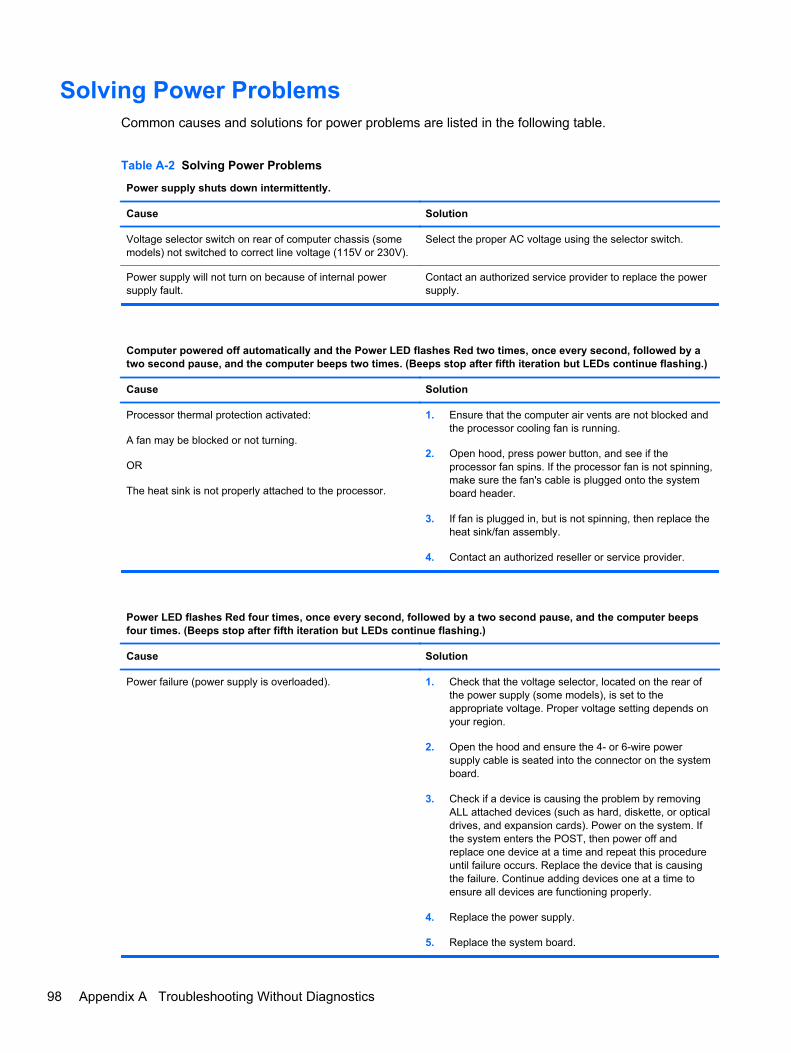
Solving Power ProblemsCommon causes and solutions for power problems are listed in the following table.
Table A-2 Solving Power Problems
Power supply shuts down intermittently.
Cause Solution
Voltage selector switch on rear of computer chassis (somemodels) not switched to correct line voltage (115V or 230V).
Select the proper AC voltage using the selector switch.
Power supply will not turn on because of internal powersupply fault.
Contact an authorized service provider to replace the powersupply.
Computer powered off automatically and the Power LED flashes Red two times, once every second, followed by atwo second pause, and the computer beeps two times. (Beeps stop after fifth iteration but LEDs continue flashing.)
Cause Solution
Processor thermal protection activated:
A fan may be blocked or not turning.
OR
The heat sink is not properly attached to the processor.
1. Ensure that the computer air vents are not blocked andthe processor cooling fan is running.
2. Open hood, press power button, and see if theprocessor fan spins. If the processor fan is not spinning,make sure the fan's cable is plugged onto the systemboard header.
3. If fan is plugged in, but is not spinning, then replace theheat sink/fan assembly.
4. Contact an authorized reseller or service provider.
Power LED flashes Red four times, once every second, followed by a two second pause, and the computer beepsfour times. (Beeps stop after fifth iteration but LEDs continue flashing.)
Cause Solution
Power failure (power supply is overloaded). 1. Check that the voltage selector, located on the rear ofthe power supply (some models), is set to theappropriate voltage. Proper voltage setting depends onyour region.
2. Open the hood and ensure the 4- or 6-wire powersupply cable is seated into the connector on the systemboard.
3. Check if a device is causing the problem by removingALL attached devices (such as hard, diskette, or opticaldrives, and expansion cards). Power on the system. Ifthe system enters the POST, then power off andreplace one device at a time and repeat this procedureuntil failure occurs. Replace the device that is causingthe failure. Continue adding devices one at a time toensure all devices are functioning properly.
4. Replace the power supply.
5. Replace the system board.
98 Appendix A Troubleshooting Without Diagnostics

Solving Diskette ProblemsCommon causes and solutions for diskette problems are listed in the following table.
NOTE: The computer does not support internal diskette drives. Only USB diskette drives aresupported.
NOTE: You may need to reconfigure the computer when you add or remove hardware, such as anadditional diskette drive. See Solving Hardware Installation Problems on page 116 for instructions.
Table A-3 Solving Diskette Problems
Diskette drive light stays on.
Cause Solution
Diskette is damaged. In Microsoft Windows XP, right-click Start, click Explore,and select a drive. Select File > Properties > Tools. UnderError-checking click Check Now.
In Microsoft Windows Vista and Windows 7, right-click Start,click Explore, and right-click on a drive. SelectProperties then select the Tools tab. Under Error-checkingclick Check Now.
Diskette is incorrectly inserted. Remove diskette and reinsert.
Drive cable is not properly connected. Reconnect drive cable. Ensure that all four pins on thediskette power cable are connected to the drive.
Drive not found.
Cause Solution
Cable is loose. Reseat diskette drive data and power cable.
Removable drive is not seated properly. Reseat the drive.
The device has been hidden in Computer Setup. Run the Computer Setup utility and ensure Device Availableis selected for the Legacy Diskette in Security > DeviceSecurity.
Diskette drive cannot write to a diskette.
Cause Solution
Diskette is not formatted. Format the diskette.
1. From Windows Explorer select the disk (A) drive.
2. Right-click the drive letter and select Format.
3. Select the desired options, and click Start to beginformatting the diskette.
Diskette is write-protected. Use another diskette or remove the write protection.
Writing to the wrong drive. Check the drive letter in the path statement.
Solving Diskette Problems 99

Table A-3 Solving Diskette Problems (continued)
Diskette drive cannot write to a diskette.
Cause Solution
Not enough space is left on the diskette. 1. Use another diskette.
2. Delete unneeded files from diskette.
Diskette is damaged. Replace the damaged disk.
Cannot format diskette.
Cause Solution
Invalid media reported. When formatting a disk in MS-DOS, you may need to specifydiskette capacity. For example, to format a 1.44-MB diskette,type the following command at the MS-DOS prompt:
FORMAT A: /F:1440
Disk may be write-protected. Open the locking device on the diskette.
Legacy diskette writes are disabled in Computer Setup. Enter Computer Setup and enable Legacy Diskette Write inStorage > Storage Options.
A problem has occurred with a disk transaction.
Cause Solution
The directory structure is bad, or there is a problem with afile.
In Microsoft Windows XP, right-click Start, click Explore,and select a drive. Select File > Properties > Tools. UnderError-checking, click Check Now.
In Microsoft Windows Vista or Windows 7, right-click Start,click Explore, and right-click on a drive. SelectProperties then select the Tools tab. Under Error-checkingclick Check Now.
Diskette drive cannot read a diskette.
Cause Solution
You are using the wrong diskette type for the drive type. Check the type of drive that you are using and use thecorrect diskette type.
You are reading the wrong drive. Check the drive letter in the path statement.
Diskette is damaged. Replace the diskette with a new one.
100 Appendix A Troubleshooting Without Diagnostics

“Invalid system disk” message is displayed.
Cause Solution
A diskette that does not contain the system files needed tostart the computer has been inserted in the drive.
When drive activity stops, remove the diskette and press theSpacebar. The computer should start up.
Diskette error has occurred. Restart the computer by pressing the power button.
Cannot Boot to Diskette.
Cause Solution
Diskette is not bootable. Replace with a bootable diskette.
Diskette boot has been disabled in Computer Setup. 1. Run Computer Setup and enable USB device inStorage > Boot Order.
2. Run Computer Setup and enable USB device inStorage > Storage Options > Removable MediaBoot.
NOTE: Both steps should be used as the RemovableMedia Boot function in Computer Setup overrides the BootOrder enable command.
Network server mode is enabled in Computer Setup. Run Computer Setup and disable Network Server Mode inSecurity > Password Options.
Solving Diskette Problems 101

Solving Hard Drive Problems
Table A-4 Solving Hard Drive Problems
Hard drive error occurs.
Cause Solution
Hard disk has bad sectors or has failed. 1. In Microsoft Windows XP, right-click Start, clickExplore, and select a drive. Select File > Properties >Tools. Under Error-checking, click Check Now.
In Microsoft Windows Vista or Windows 7, right-clickStart, click Explore, and right-click on a drive. SelectProperties then select the Tools tab. Under Error-checking click Check Now.
2. Use a utility to locate and block usage of bad sectors. Ifnecessary, reformat the hard disk.
Disk transaction problem.
Cause Solution
Either the directory structure is bad or there is a problem witha file.
In Microsoft Windows XP, right-click Start, click Explore,and select a drive. Select File > Properties > Tools. UnderError-checking, click Check Now.
In Microsoft Windows Vista or Windows 7, right-click Start,click Explore, and right-click on a drive. SelectProperties then select the Tools tab. Under Error-checkingclick Check Now.
Drive not found (identified).
Cause Solution
Cable could be loose. Check cable connections.
The system may not have automatically recognized a newlyinstalled device.
See reconfiguration directions in the Solving HardwareInstallation Problems on page 116 section. If the system stilldoes not recognize the new device, check to see if thedevice is listed within Computer Setup. If it is listed, theprobable cause is a driver problem. If it is not listed, theprobable cause is a hardware problem.
If this is a newly installed drive, run the Computer Setuputility and try adding a POST delay under Advanced >Power-On.
The device is attached to a SATA port that has been hiddenin Computer Setup.
Run the Computer Setup utility and ensure Device Availableis selected for the device's SATA port in Security > DeviceSecurity.
Drive responds slowly immediately after power-up. Run Computer Setup and increase the POST Delay inAdvanced > Power-On Options.
102 Appendix A Troubleshooting Without Diagnostics

Nonsystem disk/NTLDR missing message.
Cause Solution
The system is trying to start from a diskette that is notbootable.
Remove the diskette from the diskette drive.
The system is trying to start from the hard drive but the harddrive may have been damaged.
1. Insert a bootable diskette into the diskette drive andrestart the computer.
2. Check the hard drive format using fdisk: If NTFSformatting, use a third party reader to evaluate thedrive. If FAT32 formatting, the hard drive cannot beaccessed.
System files missing or not properly installed. 1. Insert a bootable diskette into the diskette drive andrestart the computer.
2. Check the hard drive format using Fdisk: If NFTFSformatting, use a third party reader to evaluate thedrive. If FAT32 formatting, the hard drive cannot beaccessed.
3. Install system files for the appropriate operating system.
Hard drive boot has been disabled in Computer Setup. Run the Computer Setup utility and enable the hard driveentry in the Storage > Boot Order list.
Bootable hard drive is not attached as first in a multi-harddrive configuration.
If attempting to boot from a hard drive, ensure it is attachedto the system board dark blue SATA connector.
Bootable hard drive's controller is not listed first in the BootOrder.
Run the Computer Setup utility and select Storage > BootOrder and ensure the bootable hard drive's controller islisted immediately under the Hard Drive entry.
Computer will not boot from hard drive.
Cause Solution
The device is attached to a SATA port that has been hiddenin Computer Setup.
Run the Computer Setup utility and ensure Device Availableis selected for the device's SATA port in Security > DeviceSecurity.
Boot order is not correct. Run the Computer Setup utility and change boot sequence inStorage > Boot Order.
Hard Drive's “Emulation Type” is set to “None.” Run the Computer Setup utility and change the “EmulationType” to “Hard Disk” in the device's details under Storage >Device Configuration.
Hard drive is damaged. Observe if the front panel Power LED is blinking RED and ifany beeps are heard. See Appendix A, POST ErrorMessages on page 131 to determine possible causes for theblinking red and beep codes.
See the Worldwide Limited Warranty for terms andconditions.
Solving Hard Drive Problems 103

Computer seems to be locked up.
Cause Solution
Program in use has stopped responding to commands. Attempt the normal Windows “Shut Down” procedure. If thisfails, press the power button for four or more seconds to turnoff the power. To restart the computer, press the powerbutton again.
The removable hard drive has no power to the hard drive enclosure.
Cause Solution
The lock on the enclosure is not turned to the “ON” position. Insert the key and turn the lock clockwise 90 degrees. Thegreen LED on the front of the enclosure should be on.
Power cable from the computer power supply to theenclosure frame is not properly connected.
Check the power supply to make sure it is properlyconnected to the rear of the enclosure frame.
The removable hard drive is not recognized by the computer.
Cause Solution
The removable hard drive carrier is not fully seated in theenclosure frame or the hard drive is not fully seated in thecarrier.
Push the carrier into the enclosure frame so that theconnector on the rear of the frame is properly seated. If thisdoes not solve the problem, turn off the computer, removethe carrier, and check to see if the connector on the harddrive is properly seated in the carrier.
The removable hard drive enclosure is beeping and the green LED is flashing.
Cause Solution
Fan failure alarm on the removable hard drive enclosure hasbeen activated.
Shut down the computer and contact HP for a replacementenclosure.
104 Appendix A Troubleshooting Without Diagnostics

Solving Media Card Reader Problems
Table A-5 Solving Media Card Reader Problems
Media card will not work in a digital camera after formatting it in Microsoft Windows XP or Microsoft Windows Vista.
Cause Solution
By default, Windows will format any media card with acapacity greater than 32MB with the FAT32 format. Mostdigital cameras use the FAT (FAT16 & FAT12) format andcan not operate with a FAT32 formatted card.
Either format the media card in the digital camera or selectFAT file system to format the media card in a computer withWindows.
A write-protected or locked error occurs when attempting to write to the media card.
Cause Solution
Media card is locked. Locking the media card is a safetyfeature that prevents writing to and deleting from an SD/Memory Stick/PRO card.
If using an SD card, make sure that the lock tab located onthe right of the SD card is not in the locked position. If usinga Memory Stick/PRO card, make sure that the lock tablocated on the bottom of the Memory Stick/PRO card is notin the locked position.
Can not write to the media card.
Cause Solution
The media card is a read-only memory (ROM) card. Check the manufacturer’s documentation included with yourcard to see if it writable. Refer to the previous section for alist of compatible cards.
Media card is locked. Locking the media card is a safetyfeature that prevents writing to and deleting from an SD/Memory Stick/PRO card.
If using an SD card, make sure that the lock tab located onthe right of the SD card is not in the locked position. If usinga Memory Stick/PRO card, make sure that the lock tablocated on the bottom of the Memory Stick/PRO card is notin the locked position.
Unable to access data on the media card after inserting it into a slot.
Cause Solution
The media card is not inserted properly, is inserted in thewrong slot, or is not supported.
Ensure that the card is inserted properly with the goldcontact on the correct side. The green LED will light ifinserted properly.
Solving Media Card Reader Problems 105

Do not know how to remove a media card correctly.
Cause Solution
The computer’s software is used to safely eject the card. Open My Computer (Windows XP) or Computer (WindowsVista/Windows 7), right-click on the corresponding drive icon,and select Eject. Then pull the card out of the slot.
NOTE: Never remove the card when the green LED isflashing
After installing the media card reader and booting to Windows, the reader and the inserted cards are not recognizedby the computer.
Cause Solution
The operating system needs time to recognize the device ifthe reader was just installed into the computer and you areturning the PC on for the first time.
Wait a few seconds so that the operating system canrecognize the reader and the available ports, and thenrecognize whatever media is inserted in the reader.
After inserting a media card in the reader, the computer attempts to boot from the media card.
Cause Solution
The inserted media card has boot capability. If you do not want to boot from the media card, remove itduring boot or do not select the option to boot from theinserted media card during the boot process.
106 Appendix A Troubleshooting Without Diagnostics
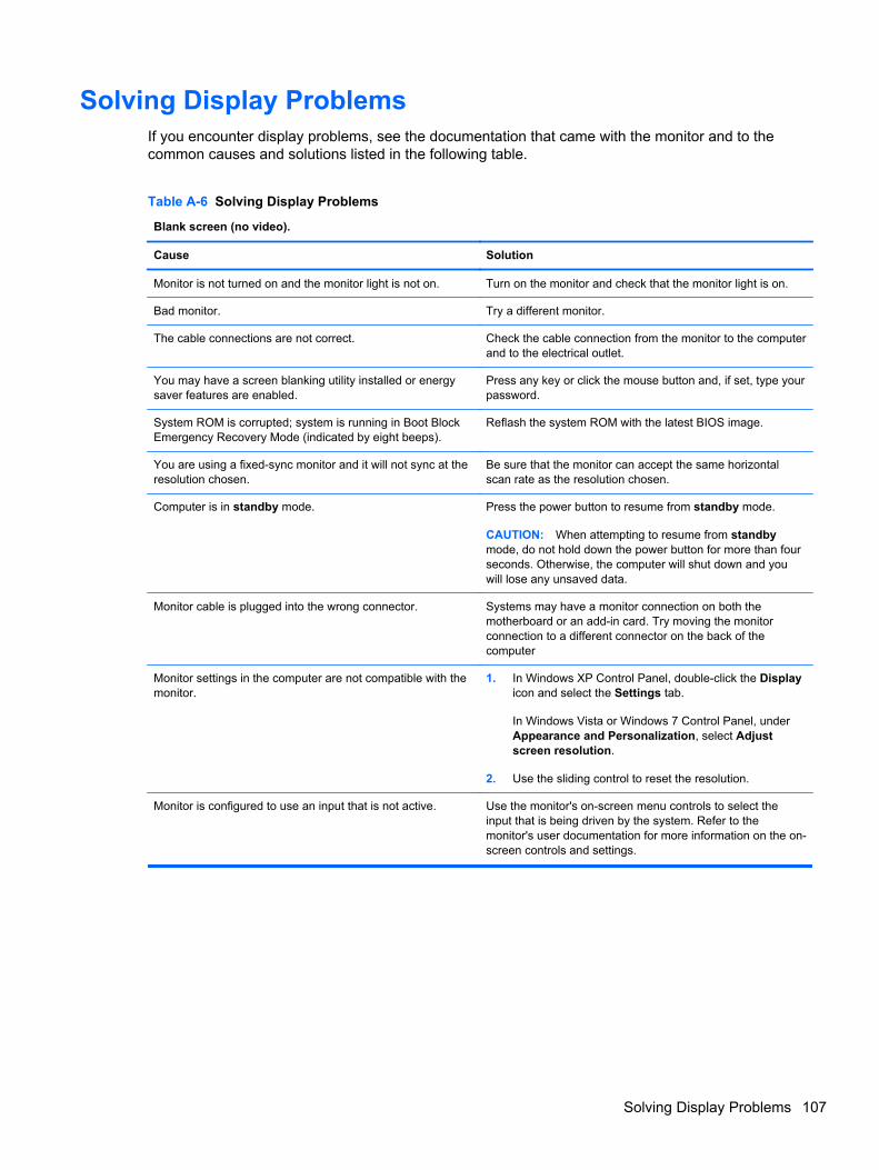
Solving Display ProblemsIf you encounter display problems, see the documentation that came with the monitor and to thecommon causes and solutions listed in the following table.
Table A-6 Solving Display Problems
Blank screen (no video).
Cause Solution
Monitor is not turned on and the monitor light is not on. Turn on the monitor and check that the monitor light is on.
Bad monitor. Try a different monitor.
The cable connections are not correct. Check the cable connection from the monitor to the computerand to the electrical outlet.
You may have a screen blanking utility installed or energysaver features are enabled.
Press any key or click the mouse button and, if set, type yourpassword.
System ROM is corrupted; system is running in Boot BlockEmergency Recovery Mode (indicated by eight beeps).
Reflash the system ROM with the latest BIOS image.
You are using a fixed-sync monitor and it will not sync at theresolution chosen.
Be sure that the monitor can accept the same horizontalscan rate as the resolution chosen.
Computer is in standby mode. Press the power button to resume from standby mode.
CAUTION: When attempting to resume from standbymode, do not hold down the power button for more than fourseconds. Otherwise, the computer will shut down and youwill lose any unsaved data.
Monitor cable is plugged into the wrong connector. Systems may have a monitor connection on both themotherboard or an add-in card. Try moving the monitorconnection to a different connector on the back of thecomputer
Monitor settings in the computer are not compatible with themonitor.
1. In Windows XP Control Panel, double-click the Displayicon and select the Settings tab.
In Windows Vista or Windows 7 Control Panel, underAppearance and Personalization, select Adjustscreen resolution.
2. Use the sliding control to reset the resolution.
Monitor is configured to use an input that is not active. Use the monitor's on-screen menu controls to select theinput that is being driven by the system. Refer to themonitor's user documentation for more information on the on-screen controls and settings.
Solving Display Problems 107

Blank screen and the power LED flashes Red five times, once every second, followed by a two second pause, andthe computer beeps five times. (Beeps stop after fifth iteration but LEDs continue flashing.)
Cause Solution
Pre-video memory error. 1. Reseat DIMMs. Power on the system.
2. Replace DIMMs one at a time to isolate the faultymodule.
3. Replace third-party memory with HP memory.
4. Replace the system board.
Blank screen and the power LED flashes Red six times, once every second, followed by a two second pause, andthe computer beeps six times. (Beeps stop after fifth iteration but LEDs continue flashing.)
Cause Solution
Pre-video graphics error. For systems with a graphics card:
1. Reseat the graphics card. Power on the system.
2. Replace the graphics card.
3. Replace the system board.
For systems with integrated graphics, replace the systemboard.
Blank screen and the power LED flashes Red seven times, once every second, followed by a two second pause, andthe computer beeps seven times. (Beeps stop after fifth iteration but LEDs continue flashing.)
Cause Solution
System board failure (ROM detected failure prior to video). Replace the system board.
Monitor does not function properly when used with energy saver features.
Cause Solution
Monitor without energy saver capabilities is being used withenergy saver features enabled.
Disable monitor energy saver feature.
Dim characters.
Cause Solution
The brightness and contrast controls are not set properly. Adjust the monitor brightness and contrast controls.
Cables are not properly connected. Check that the graphics cable is securely connected to thegraphics card and the monitor.
108 Appendix A Troubleshooting Without Diagnostics

Blurry video or requested resolution cannot be set.
Cause Solution
If the graphics controller was upgraded, the correct graphicsdrivers may not be loaded.
Install the video drivers included in the upgrade kit.
Monitor is not capable of displaying requested resolution. Change requested resolution.
Graphics card is bad. Replace the graphics card.
The picture is broken up, rolls, jitters, or flashes.
Cause Solution
The monitor connections may be incomplete or the monitormay be incorrectly adjusted.
1. Be sure the monitor cable is securely connected to thecomputer.
2. In a two-monitor system or if another monitor is in closeproximity, be sure the monitors are not interfering witheach other’s electromagnetic field by moving themapart.
3. Fluorescent lights or fans may be too close to themonitor.
Monitor needs to be degaussed. Degauss the monitor. Refer to the documentation that camewith the monitor for instructions.
Image is not centered.
Cause Solution
Position may need adjustment. Press the monitor's Menu button to access the OSD menu.Select ImageControl/ Horizontal Position or VerticalPosition to adjust the horizontal or vertical position of theimage.
“No Connection, Check Signal Cable” displays on screen.
Cause Solution
Monitor video cable is disconnected. Connect the video cable between the monitor and computer.
CAUTION: Ensure that the computer power is off whileconnecting the video cable.
“Out of Range” displays on screen.
Cause Solution
Video resolution and refresh rate are set higher than whatthe monitor supports.
Restart the computer and enter Safe Mode. Change thesettings to a supported setting then restart the computer sothat the new settings take effect.
Solving Display Problems 109

Vibrating or rattling noise coming from inside a CRT monitor when powered on.
Cause Solution
Monitor degaussing coil has been activated. None. It is normal for the degaussing coil to be activatedwhen the monitor is powered on.
Clicking noise coming from inside a CRT monitor.
Cause Solution
Electronic relays have been activated inside the monitor. None. It is normal for some monitors to make a clicking noisewhen turned on and off, when going in and out of standbymode, and when changing resolutions.
High pitched noise coming from inside a flat panel monitor.
Cause Solution
Brightness and/or contrast settings are too high. Lower brightness and/or contrast settings.
Fuzzy focus; streaking, ghosting, or shadowing effects; horizontal scrolling lines; faint vertical bars; or unable tocenter the picture on the screen (flat panel monitors using an analog VGA input connection only).
Cause Solution
Flat panel monitor’s internal digital conversion circuits maybe unable to correctly interpret the output synchronization ofthe graphics card.
1. Select the monitor’s Auto-Adjustment option in themonitor’s on-screen display menu.
2. Manually synchronize the Clock and Clock Phase on-screen display functions. To download a SoftPaq thatwill assist you with the synchronization, go to thefollowing Web site, select the appropriate monitor, anddownload either SP32347 or SP32202:http://www.hp.com/support
Graphics card is not seated properly or is bad. 1. Reseat the graphics card.
2. Replace the graphics card.
Certain typed symbols do not appear correct.
Cause Solution
The font you are using does not support that particularsymbol.
Use the Character Map to locate and select the appropriatesymbol. Click Start > All Programs > Accessories >System Tools > Character Map. You can copy the symbolfrom the Character Map into a document.
110 Appendix A Troubleshooting Without Diagnostics

Solving Audio ProblemsIf the computer has audio features and you encounter audio problems, see the common causes andsolutions listed in the following table.
Table A-7 Solving Audio Problems
Sound cuts in and out.
Cause Solution
Processor resources are being used by other openapplications.
Shut down all open processor-intensive applications.
Direct sound latency, common in many media playerapplications.
In Windows XP only:
1. From the Control Panel, select Sounds and AudioDevices.
2. On the Audio tab, select a device from the SoundPlayback list.
3. Click the Advanced button and select the Performancetab.
4. Set the Hardware acceleration slider to None and theSample rate conversion quality slider to Good andretest the audio.
5. Set the Hardware acceleration slider to Full and theSample rate conversion quality slider to Best andretest the audio.
Sound does not come out of the speaker or headphones.
Cause Solution
Software volume control is turned down or muted. Double-click the Speaker icon on the taskbar, then makesure that Mute is not selected and use the volume slider toadjust the volume.
Audio is hidden in Computer Setup. Enable the audio in Computer Setup: Security >Device Security > System Audio.
The external speakers are not turned on. Turn on the external speakers.
The audio device may be connected to the wrong jack. Ensure that the device is connected to the correct jack on thecomputer. The speakers should be plugged into the rear line-out jack and the headphones should be plugged into thefront headphone jack.
External speakers plugged into the wrong audio jack on arecently installed sound card.
See the sound card documentation for proper speakerconnection.
Digital CD audio is not enabled. Enable digital CD audio. In the Device Manager, right-clickon the CD/DVD device and select Properties. Make sureEnable digital CD audio for this CD-ROM device ischecked.
Headphones or devices connected to the line-out connectormute the internal speaker.
Turn on and use headphones or external speakers, ifconnected, or disconnect headphones or external speakers.
Solving Audio Problems 111
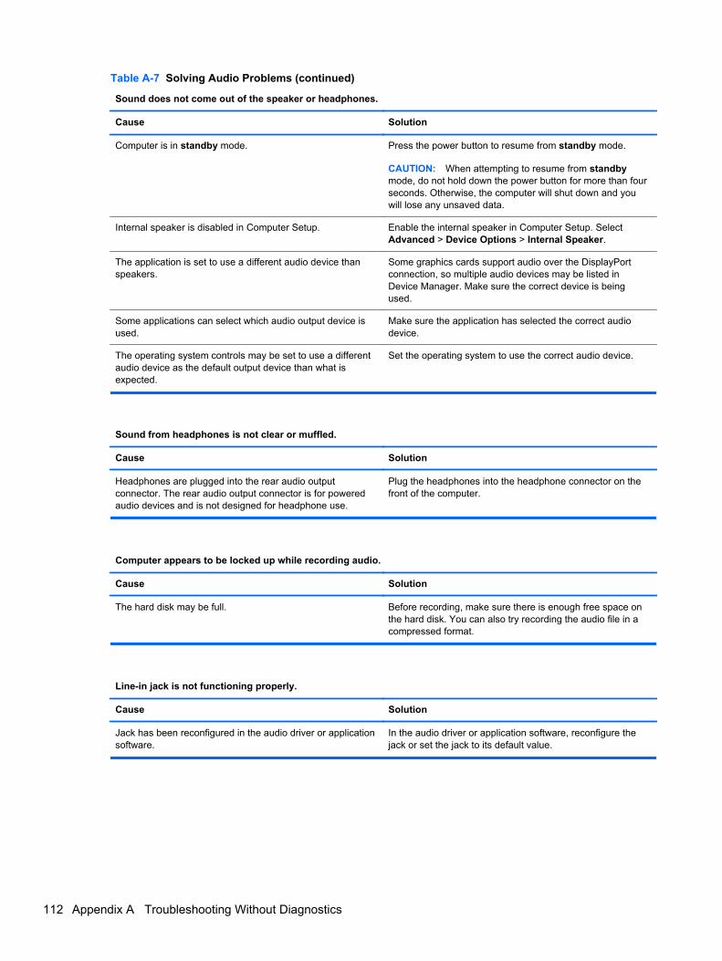
Table A-7 Solving Audio Problems (continued)
Sound does not come out of the speaker or headphones.
Cause Solution
Computer is in standby mode. Press the power button to resume from standby mode.
CAUTION: When attempting to resume from standbymode, do not hold down the power button for more than fourseconds. Otherwise, the computer will shut down and youwill lose any unsaved data.
Internal speaker is disabled in Computer Setup. Enable the internal speaker in Computer Setup. SelectAdvanced > Device Options > Internal Speaker.
The application is set to use a different audio device thanspeakers.
Some graphics cards support audio over the DisplayPortconnection, so multiple audio devices may be listed inDevice Manager. Make sure the correct device is beingused.
Some applications can select which audio output device isused.
Make sure the application has selected the correct audiodevice.
The operating system controls may be set to use a differentaudio device as the default output device than what isexpected.
Set the operating system to use the correct audio device.
Sound from headphones is not clear or muffled.
Cause Solution
Headphones are plugged into the rear audio outputconnector. The rear audio output connector is for poweredaudio devices and is not designed for headphone use.
Plug the headphones into the headphone connector on thefront of the computer.
Computer appears to be locked up while recording audio.
Cause Solution
The hard disk may be full. Before recording, make sure there is enough free space onthe hard disk. You can also try recording the audio file in acompressed format.
Line-in jack is not functioning properly.
Cause Solution
Jack has been reconfigured in the audio driver or applicationsoftware.
In the audio driver or application software, reconfigure thejack or set the jack to its default value.
112 Appendix A Troubleshooting Without Diagnostics

There is no sound or sound volume is too low.
Cause Solution
The application is set to use a different audio device thanspeakers.
Some graphics cards support audio over the DisplayPortconnection, so multiple audio devices may be listed inDevice Manager. Make sure the correct device is beingused.
Some applications can select which audio output device isused.
Make sure the application has selected the correct audiodevice.
The operating system controls may be set to use a differentaudio device as the default output device than what isexpected.
Set the operating system to use the correct audio device.
Solving Printer ProblemsIf you encounter printer problems, see the documentation that came with the printer and to thecommon causes and solutions listed in the following table.
Table A-8 Solving Printer Problems
Printer will not print.
Cause Solution
Printer is not turned on and online. Turn the printer on and make sure it is online.
The correct printer drivers for the application are notinstalled.
1. Install the correct printer driver for the application.
2. Try printing using the MS-DOS command:
DIR C:\ > [printer port]
where [printer port] is the address of the printer beingused. If the printer works, reload the printer driver.
If you are on a network, you may not have made theconnection to the printer.
Make the proper network connections to the printer.
Printer may have failed. Run printer self-test.
Printer will not turn on.
Cause Solution
The cables may not be connected properly. Reconnect all cables and check the power cord andelectrical outlet.
Printer prints garbled information.
Cause Solution
The correct printer driver for the application is not installed. Install the correct printer driver for the application.
Solving Printer Problems 113

Table A-8 Solving Printer Problems (continued)
Printer prints garbled information.
Cause Solution
The cables may not be connected properly. Reconnect all cables.
Printer memory may be overloaded. Reset the printer by turning it off for one minute, then turn itback on.
Printer is offline.
Cause Solution
The printer may be out of paper. Check the paper tray and refill it if it is empty. Select online.
Solving Keyboard and Mouse ProblemsIf you encounter keyboard or mouse problems, see the documentation that came with the equipmentand to the common causes and solutions listed in the following table.
Table A-9 Solving Keyboard Problems
Keyboard commands and typing are not recognized by the computer.
Cause Solution
Keyboard connector is not properly connected. 1. On the Windows XP Desktop, click Start > Shut Down.
On the Windows Vista or Windows 7 Desktop, clickStart, click the arrow on the lower right corner of theStart menu, then select Shut Down.
2. After the shutdown is complete, reconnect the keyboardto the back of the computer and restart the computer.
Program in use has stopped responding to commands. Shut down your computer using the mouse and then restartthe computer.
Keyboard needs repairs. See the Worldwide Limited Warranty for terms andconditions.
Computer is in standby mode. Press the power button to resume from standby mode.
CAUTION: When attempting to resume from standbymode, do not hold down the power button for more than fourseconds. Otherwise, the computer will shut down and youwill lose any unsaved data.
Cursor will not move using the arrow keys on the keypad.
Cause Solution
The Num Lock key may be on. Press the Num Lock key. The Num Lock light should not beon if you want to use the arrow keys. The Num Lock key canbe disabled (or enabled) in Computer Setup.
114 Appendix A Troubleshooting Without Diagnostics

Table A-10 Solving Mouse Problems
Mouse does not respond to movement or is too slow.
Cause Solution
Mouse connector is not properly plugged into the back of thecomputer.
Shut down the computer using the keyboard.
1. Press the Ctrl and Esc keys at the same time (or pressthe Windows logo key) to display the Start menu.
2. Use the arrow keys to select Shut Down and thenpress the Enter key.
3. After the shutdown is complete, plug the mouseconnector into the back of the computer (or thekeyboard) and restart.
Program in use has stopped responding to commands. Shut down the computer using the keyboard then restart thecomputer.
Mouse may need cleaning. Remove the roller ball cover on the mouse and clean theinternal components.
Mouse may need repair. See the Worldwide Limited Warranty for terms andconditions.
Computer is in standby mode. Press the power button to resume from standby mode.
CAUTION: When attempting to resume from standbymode, do not hold down the power button for more than fourseconds. Otherwise, the computer will shut down and youwill lose any unsaved data.
Mouse will only move vertically, horizontally, or movement is jerky.
Cause Solution
Mouse roller ball or the rotating encoder shafts that makecontact with the ball are dirty.
Remove roller ball cover from the bottom of the mouse andclean the internal components with a mouse cleaning kitavailable from most computer stores.
Solving Keyboard and Mouse Problems 115

Solving Hardware Installation ProblemsYou may need to reconfigure the computer when you add or remove hardware, such as an additionaldrive or expansion card. If you install a plug and play device, Windows automatically recognizes thedevice and configures the computer. If you install a non–plug and play device, you must reconfigurethe computer after completing installation of the new hardware. In Windows, use the Add HardwareWizard and follow the instructions that appear on the screen.
WARNING! When the computer is plugged into an AC power source, voltage is always applied tothe system board. To reduce the risk of personal injury from electrical shock and/or hot surfaces, besure to disconnect the power cord from the wall outlet and allow the internal system components tocool before touching.
Table A-11 Solving Hardware Installation Problems
A new device is not recognized as part of the system.
Cause Solution
Device is not seated or connected properly. Ensure that the device is properly and securely connectedand that pins in the connector are not bent down.
Cable(s) of new external device are loose or power cablesare unplugged.
Ensure that all cables are properly and securely connectedand that pins in the cable or connector are not bent down.
Power switch of new external device is not turned on. Turn off the computer, turn on the external device, then turnon the computer to integrate the device with the computersystem.
When the system advised you of changes to theconfiguration, you did not accept them.
Reboot the computer and follow the instructions foraccepting the changes.
A plug and play board may not automatically configure whenadded if the default configuration conflicts with other devices.
Use Windows Device Manager to deselect the automaticsettings for the board and choose a basic configuration thatdoes not cause a resource conflict. You can also useComputer Setup to reconfigure or disable devices to resolvethe resource conflict.
USB ports on the computer are disabled in Computer Setup. Run the Computer Setup utility and ensure that Deviceavailable is selected for appropriate USB ports underSecurity > USB Security.
Computer will not start.
Cause Solution
Wrong memory modules were used in the upgrade ormemory modules were installed in the wrong location.
1. Review the documentation that came with the system todetermine if you are using the correct memory modulesand to verify the proper installation.
NOTE: DIMM1 or XMM1 must always be installed.
2. Observe the beeps and LED lights on the front of thecomputer. Beeps and flashing LEDs are codes forspecific problems.
3. If you still cannot resolve the issue, contact CustomerSupport.
116 Appendix A Troubleshooting Without Diagnostics

Power LED flashes Red five times, once every second, followed by a two second pause, and the computer beepsfive times. (Beeps stop after fifth iteration but LEDs continue flashing.)
Cause Solution
Memory is installed incorrectly or is bad. CAUTION: To avoid damage to the DIMMs or the systemboard, you must unplug the computer power cord beforeattempting to reseat, install, or remove a DIMM module.
1. Reseat DIMMs. Power on the system.
2. Replace DIMMs one at a time to isolate the faultymodule.
NOTE: DIMM1 or XMM1 must always be installed.
3. Replace third-party memory with HP memory.
4. Replace the system board.
Power LED flashes Red six times, once every second, followed by a two second pause, and the computer beeps sixtimes. (Beeps stop after fifth iteration but LEDs continue flashing.)
Cause Solution
Graphics card is not seated properly or is bad, or systemboard is bad.
For systems with a graphics card:
1. Reseat the graphics card. Power on the system.
2. Replace the graphics card.
3. Replace the system board.
For systems with integrated graphics, replace the systemboard.
Power LED flashes Red ten times, once every second, followed by a two second pause, and the computer beeps tentimes. (Beeps stop after fifth iteration but LEDs continue flashing.)
Cause Solution
Bad option card. 1. Check each option card by removing the cards one attime (if multiple cards), then power on the system to seeif fault goes away.
2. Once bad card is identified, remove and replace badoption card.
3. Replace the system board.
Solving Network ProblemsSome common causes and solutions for network problems are listed in the following table. Theseguidelines do not discuss the process of debugging the network cabling.
Solving Network Problems 117

Table A-12 Solving Network Problems
Wake-on-LAN feature is not functioning.
Cause Solution
S5 Maximum Power Saving feature is enabled. Disable the S5 Maximum Power Saving option in ComputerSetup. Select Power > Hardware Power Management > S5Maximum Power Saving.
S5 Wake on LAN is disabled. : Enable the S5 Wake on LAN option in Computer Setup.Select Advanced > Device Options > S5 Wake on LAN.
Wake-on-LAN is not enabled. To enable Wake-on-LAN in Windows XP:
1. Select Start > Control Panel.
2. Double-click Network Connections.
3. Double-click Local Area Connection.
4. Click Properties.
5. Click Configure.
6. Click the Power Management tab, then select thecheck box to Allow this device to bring the computerout of standby.
To enable Wake-on-LAN in Windows Vista:
1. Select Start > Control Panel.
2. Under Network and Internet, select View networkstatus and tasks.
3. In the Tasks list, select Manage network connections.
4. Double-click Local Area Connection.
5. Click the Properties button.
6. Click the Configure button.
7. Click the Power Management tab, then select thecheck box to Allow this device to wake the computer.
To enable Wake-on-LAN in Windows 7:
1. Select Start > Control Panel.
2. Under Network and Internet, select View networkstatus and tasks.
3. Click Local Area Connection.
4. Click the Properties button.
5. Click the Configure button.
6. Click the Power Management tab, then select thecheck box to Allow this device to wake the computer.
118 Appendix A Troubleshooting Without Diagnostics

Network driver does not detect network controller.
Cause Solution
Network controller is disabled. 1. Run Computer Setup and enable network controller.
2. Enable the network controller in the operating systemvia Device Manager.
Incorrect network driver. Check the network controller documentation for the correctdriver or obtain the latest driver from the manufacturer’s Website.
Network status link light never flashes.
NOTE: The network status light is supposed to flash when there is network activity.
Cause Solution
No active network is detected. Check cabling and network equipment for proper connection.
Network controller is not set up properly. Check for the device status within Windows, such as DeviceManager for driver load and the Network Connections appletwithin Windows for link status.
Network controller is disabled. 1. Run Computer Setup and enable network controller.
2. Enable the network controller in the operating systemvia Device Manager.
Network driver is not properly loaded. Reinstall network drivers.
System cannot autosense the network. Disable auto-sensing capabilities and force the system intothe correct operating mode.
Diagnostics reports a failure.
Cause Solution
The cable is not securely connected. Ensure that the cable is securely attached to the networkconnector and that the other end of the cable is securelyattached to the correct device.
The cable is attached to the incorrect connector. Ensure that the cable is attached to the correct connector.
There is a problem with the cable or a device at the otherend of the cable.
Ensure that the cable and device at the other end areoperating correctly.
Network controller interrupt is shared with an expansionboard.
Under the Computer Setup Advanced menu, change theresource settings for the board.
The network controller is defective. Contact an authorized service provider.
Solving Network Problems 119

Diagnostics passes, but the computer does not communicate with the network.
Cause Solution
Network drivers are not loaded, or driver parameters do notmatch current configuration.
Make sure the network drivers are loaded and that the driverparameters match the configuration of the network controller.
Make sure the correct network client and protocol is installed.
The network controller is not configured for this computer. Select the Network icon in the Control Panel and configurethe network controller.
Network controller stopped working when an expansion board was added to the computer.
Cause Solution
Network controller interrupt is shared with an expansionboard.
Under the Computer Setup Advanced menu, change theresource settings for the board.
The network controller requires drivers. Verify that the drivers were not accidentally deleted when thedrivers for a new expansion board were installed.
The expansion board installed is a network card (NIC) andconflicts with the embedded NIC.
Under the Computer Setup Advanced menu, change theresource settings for the board.
Network controller stops working without apparent cause.
Cause Solution
The files containing the network drivers are corrupted. Reinstall the network drivers, using the Recovery Disc Setcreated from the hard drive's Recovery Partition.
The cable is not securely connected. Ensure that the cable is securely attached to the networkconnector and that the other end of the cable is securelyattached to the correct device.
The network controller is defective. Contact an authorized service provider.
New network card will not boot.
Cause Solution
New network card may be defective or may not meetindustry-standard specifications.
Install a working, industry-standard NIC, or change the bootsequence to boot from another source.
Cannot connect to network server when attempting Remote System Installation.
Cause Solution
The network controller is not configured properly. Verify Network Connectivity, that a DHCP Server is present,and that the Remote System Installation Server contains theNIC drivers for your NIC.
120 Appendix A Troubleshooting Without Diagnostics

System setup utility reports unprogrammed EEPROM.
Cause Solution
Unprogrammed EEPROM. Contact an authorized service provider.
Solving Memory ProblemsIf you encounter memory problems, some common causes and solutions are listed in the followingtable.
CAUTION: Power may still be supplied to the DIMMs when the computer is turned off (dependingon the Management Engine (ME) settings). To avoid damage to the DIMMs or the system board, youmust unplug the computer power cord before attempting to reseat, install, or remove a DIMM module.
For those systems that support ECC memory, HP does not support mixing ECC and non-ECCmemory. Otherwise, the computer will not boot the operating system.
NOTE: The memory count will be affected by configurations with the Management Engine (ME)enabled. The ME uses 8MB of system memory in single channel mode or 16MB of memory in dual-channel mode to download, decompress, and execute the ME firmware for Out-of-Band (OOB), third-party data storage, and other management functions.
Table A-13 Solving Memory Problems
System will not boot or does not function properly after installing additional memory modules.
Cause Solution
A memory module is not installed in the DIMM1 or XMM1socket.
Ensure that a memory module is installed in the DIMM1 orXMM1 socket on the system board. This socket must bepopulated with a memory module.
Memory module is not the correct type or speed grade forthe system or the new memory module is not seatedproperly.
Replace module with the correct industry-standard device forthe computer. On some models, ECC and non-ECC memorymodules cannot be mixed.
Out of memory error.
Cause Solution
Memory configuration may not be set up correctly. Use the Device Manager to check memory configuration.
You have run out of memory to run the application. Check the application documentation to determine thememory requirements.
Memory count during POST is wrong.
Cause Solution
The memory modules may not be installed correctly. Check that the memory modules have been installedcorrectly and that proper modules are used.
Integrated graphics may use system memory. No action required.
Solving Memory Problems 121

Insufficient memory error during operation.
Cause Solution
Too many Terminate and Stay Resident programs (TSRs)are installed.
Delete any TSRs that you do not need.
You have run out of memory for the application. Check the memory requirements for the application or addmore memory to the computer.
Power LED flashes Red five times, once every second, followed by a two second pause, and the computer beepsfive times. (Beeps stop after fifth iteration but LEDs continue flashing.)
Cause Solution
Memory is installed incorrectly or is bad. 1. Reseat DIMMs. Power on the system.
2. Replace DIMMs one at a time to isolate the faultymodule.
3. Replace third-party memory with HP memory.
4. Replace the system board.
Solving Processor ProblemsIf you encounter processor problems, common causes and solutions are listed in the following table.
Table A-14 Solving Processor Problems
Poor performance is experienced.
Cause Solution
Processor is hot. 1. Make sure the airflow to the computer is not blocked.
2. Make sure the fans are connected and working properly(some fans only operate when needed).
3. Make sure the processor heat sink is installed properly.
Power LED flashes Red three times, once every second, followed by a two second pause.
Cause Solution
Processor is not seated properly or not installed. 1. Check to see that the processor is present.
2. Reseat the processor.
122 Appendix A Troubleshooting Without Diagnostics

Power LED flashes Red eleven times, once every second, followed by a two second pause.
Cause Solution
The current processor does not support a feature previouslyenabled on this system.
1. Install a TXT capable processor.
2. Disable TXT in the Computer Setup (F10) utility.
3. Reinstall the original processor.
Solving CD-ROM and DVD ProblemsIf you encounter CD-ROM or DVD problems, see the common causes and solutions listed in thefollowing table or to the documentation that came with the optional device.
Table A-15 Solving CD-ROM and DVD Problems
System will not boot from CD-ROM or DVD drive.
Cause Solution
The device is attached to a SATA port that has been hiddenin the Computer Setup utility.
Run the Computer Setup utility and ensure Device Availableis selected for the device's SATA port in Security > DeviceSecurity.
Removable Media Boot is disabled in the Computer Setuputility.
Run the Computer Setup utility and enable booting toremovable media in Storage > Storage Options. EnsureCD-ROM is enabled in Storage > Boot Order.
Network Server Mode is enabled in Computer Setup. Run the Computer Setup utility and disable Network ServerMode in Security > Password Options.
Non-bootable CD in drive. Try a bootable CD in the drive.
Boot order not correct. Run the Computer Setup utility and change boot sequence inStorage > Boot Order.
Drive not found (identified).
Cause Solution
Cable could be loose. Check cable connections.
The system may not have automatically recognized a newlyinstalled device.
See reconfiguration directions in the Solving HardwareInstallation Problems on page 116 section. If the system stilldoes not recognize the new device, check to see if thedevice is listed within Computer Setup. If it is listed, theprobable cause is a driver problem. If it is not listed, theprobable cause is a hardware problem.
If this is a newly installed drive, run the Computer Setuputility and try adding a POST delay under Advanced >Power-On Options.
The device is attached to a SATA port that has been hiddenin Computer Setup.
Run the Computer Setup utility and ensure Device Availableis selected for the device's SATA port in Security > DeviceSecurity.
Drive responds slowly immediately after power-up. Run Computer Setup and increase the POST Delay inAdvanced > Power-On Options.
Solving CD-ROM and DVD Problems 123

CD-ROM or DVD devices are not detected or driver is not loaded.
Cause Solution
Drive is not connected properly or not properly configured. See the documentation that came with the optional device.
Movie will not play in the DVD drive.
Cause Solution
Movie may be regionalized for a different country. See the documentation that came with the DVD drive.
Decoder software is not installed. Install decoder software.
Damaged media. Replace media.
Movie rating locked out by parental lock. Use DVD software to remove parental lock.
Media installed upside down. Reinstall media.
Cannot eject compact disc (tray-load unit).
Cause Solution
Disc not properly seated in the drive. Turn off the computer and insert a thin metal rod into theemergency eject hole and push firmly. Slowly pull the trayout from the drive until the tray is fully extended, then removethe disc.
CD-ROM, CD-RW, DVD-ROM, or DVD-R/RW drive cannot read a disc or takes too long to start.
Cause Solution
Media has been inserted upside down. Re-insert the media with the label facing up.
The DVD-ROM drive takes longer to start because it has todetermine the type of media played, such as audio or video.
Wait at least 30 seconds to let the DVD-ROM drivedetermine the type of media being played. If the disc stilldoes not start, read the other solutions listed for this topic.
CD or DVD disc is dirty. Clean CD or DVD with a CD cleaning kit, available from mostcomputer stores.
Windows does not detect the CD-ROM or DVD-ROM drive. 1. Use Device Manager to remove or uninstall the device.
2. Restart the computer and let Windows detect the CD orDVD driver.
124 Appendix A Troubleshooting Without Diagnostics

Recording or copying CDs is difficult or impossible.
Cause Solution
Wrong or poor quality media type. 1. Try using a slower speed when recording.
2. Verify that you are using the correct media for the drive.
3. Try a different brand of media. Quality varies widelybetween manufacturers.
Solving USB Flash Drive ProblemsIf you encounter USB flash drive problems, common causes and solutions are listed in the followingtable.
Table A-16 Solving USB Flash Drive Problems
USB flash drive is not seen as a drive letter in Windows.
Cause Solution
The drive letter after the last physical drive is not available. Change the default drive letter for the flash drive in Windows.
USB flash drive not found (identified).
Cause Solution
The device is attached to a USB port that has been hidden inComputer Setup.
Run the Computer Setup utility and ensure that “Deviceavailable” is selected for “Front USB Ports” and “Rear USBPorts” under Security > Device Security.
The device was not properly seated before power-up. Ensure the device is fully inserted into the USB port beforeapplying power to the system
System will not boot from USB flash drive.
Cause Solution
Boot order is not correct. Run the Computer Setup utility and change boot sequence inStorage > Boot Order.
Removable Media Boot is disabled in the Computer Setuputility.
Run the Computer Setup utility and enable booting toremovable media in Storage > Storage Options. EnsureUSB is enabled in Storage > Boot Order.
The computer boots to DOS after making a bootable flash drive.
Cause Solution
Flash drive is bootable. Install the flash drive only after the operating system boots.
Solving USB Flash Drive Problems 125

Solving Front Panel Component ProblemsIf you encounter problems with devices connected to the front panel, refer to the common causes andsolutions listed in the following table.
Table A-17 Solving Front Panel Component Problems
A USB device, headphone, or microphone is not recognized by the computer.
Cause Solution
Device is not properly connected. 1. Turn off the computer.
2. Reconnect the device to the front of the computer andrestart the computer.
The device does not have power. If the USB device requires AC power, be sure one end isconnected to the device and one end is connected to a liveoutlet.
The correct device driver is not installed. 1. Install the correct driver for the device.
2. You might need to reboot the computer.
The cable from the device to the computer does not work. 1. If possible, replace the cable.
2. Restart the computer.
The device is not working. 1. Replace the device.
2. Restart the computer.
USB ports on the computer are disabled in Computer Setup. Run the Computer Setup utility and ensure that Deviceavailable is selected for appropriate USB ports underSecurity > USB Security.
Solving Internet Access ProblemsIf you encounter Internet access problems, consult your Internet Service Provider (ISP) or refer to thecommon causes and solutions listed in the following table.
Table A-18 Solving Internet Access Problems
Unable to connect to the Internet.
Cause Solution
Internet Service Provider (ISP) account is not set upproperly.
Verify Internet settings or contact your ISP for assistance.
Modem is not set up properly. Reconnect the modem. Verify the connections are correctusing the quick setup documentation.
Web browser is not set up properly. Verify that the Web browser is installed and set up to workwith your ISP.
Cable/DSL modem is not plugged in. Plug in cable/DSL modem. You should see a “power” LEDlight on the front of the cable/DSL modem.
126 Appendix A Troubleshooting Without Diagnostics

Table A-18 Solving Internet Access Problems (continued)
Unable to connect to the Internet.
Cause Solution
Cable/DSL service is not available or has been interrupteddue to bad weather.
Try connecting to the Internet at a later time or contact yourISP. (If the cable/DSL service is connected, the “cable” LEDlight on the front of the cable/DSL modem will be on.)
The CAT5 UTP cable is disconnected. Connect the CAT5 UTP cable between the cable modemand the computers’s RJ-45 connector. (If the connection isgood, the “PC” LED light on the front of the cable/DSLmodem will be on.)
IP address is not configured properly. Contact your ISP for the correct IP address.
Cookies are corrupted. (A “cookie” is a small piece ofinformation that a Web server can store temporarily with theWeb browser. This is useful for having the browserremember some specific information that the Web server canlater retrieve.)
Windows 7
1. Select Start > Control Panel.
2. Click Network and Internet.
3. Click Internet Options.
4. In the Browsing history section on the General tab,click the Delete button.
5. Select the Cookies check box and click the Deletebutton.
Windows Vista
1. Select Start > Control Panel.
2. Click Network and Internet.
3. Click Internet Options.
4. In the Browsing history section on the General tab,click the Delete button.
5. Click the Delete cookies button.
Windows XP
1. Select Start > Control Panel.
2. Double-click Internet Options.
3. On the General tab, click the Delete Cookies button.
Cannot automatically launch Internet programs.
Cause Solution
You must log on to your ISP before some programs will start. Log on to your ISP and launch the desired program.
Solving Internet Access Problems 127

Internet takes too long to download Web sites.
Cause Solution
Modem is not set up properly. Verify that the modem is connected and communicatingproperly.
Windows 7
1. Select Start > Control Panel.
2. Click on Hardware and Sound.
3. Click on Device Manager.
4. Double-click Modems.
5. Double-click Agere Systems PCI-SV92PP SoftModem.
6. On the General tab, click Diagnostics.
7. Click Query Modem. A “Success” response indicatesthe modem is connected and working properly.
Windows XP
1. Select Start > Control Panel.
2. Double-click System.
3. Click the Hardware tab.
4. In the Device Manager area, click the Device Managerbutton.
5. Double-click Modems.
6. Double-click Agere Systems PCI-SV92PP SoftModem.
7. On the General tab, click Diagnostics.
8. Click Query Modem. A “Success” response indicatesthe modem is connected and working properly.
Windows Vista
1. Select Start > Control Panel.
2. Click on System and Maintenance.
3. Click on System.
4. In the Tasks list, select Device Manager.
5. Double-click Modems.
6. Double-click Agere Systems PCI-SV92PP SoftModem.
7. On the General tab, click Diagnostics.
8. Click Query Modem. A “Success” response indicatesthe modem is connected and working properly.
128 Appendix A Troubleshooting Without Diagnostics
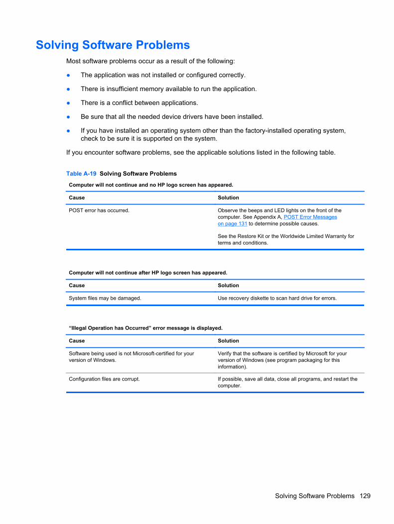
Solving Software ProblemsMost software problems occur as a result of the following:
● The application was not installed or configured correctly.
● There is insufficient memory available to run the application.
● There is a conflict between applications.
● Be sure that all the needed device drivers have been installed.
● If you have installed an operating system other than the factory-installed operating system,check to be sure it is supported on the system.
If you encounter software problems, see the applicable solutions listed in the following table.
Table A-19 Solving Software Problems
Computer will not continue and no HP logo screen has appeared.
Cause Solution
POST error has occurred. Observe the beeps and LED lights on the front of thecomputer. See Appendix A, POST Error Messageson page 131 to determine possible causes.
See the Restore Kit or the Worldwide Limited Warranty forterms and conditions.
Computer will not continue after HP logo screen has appeared.
Cause Solution
System files may be damaged. Use recovery diskette to scan hard drive for errors.
“Illegal Operation has Occurred” error message is displayed.
Cause Solution
Software being used is not Microsoft-certified for yourversion of Windows.
Verify that the software is certified by Microsoft for yourversion of Windows (see program packaging for thisinformation).
Configuration files are corrupt. If possible, save all data, close all programs, and restart thecomputer.
Solving Software Problems 129

Contacting Customer SupportFor help and service, contact an authorized reseller or dealer. To locate a reseller or dealer near you,visit http://www.hp.com.
NOTE: If you take the computer to an authorized reseller, dealer, or service provider for service,remember to provide the setup and power-on passwords if they are set.
Refer to the number listed in the warranty or in the Support Telephone Numbers guide for technicalassistance.
130 Appendix A Troubleshooting Without Diagnostics

B POST Error Messages
This appendix lists the error codes, error messages, and the various indicator light and audiblesequences that you may encounter during Power-On Self-Test (POST) or computer restart, theprobable source of the problem, and steps you can take to resolve the error condition.
POST Message Disabled suppresses most system messages during POST, such as memory countand non-error text messages. If a POST error occurs, the screen will display the error message. Tomanually switch to the POST Messages Enabled mode during POST, press any key (except F10,F11, or F12). The default mode is POST Message Disabled.
The speed at which the computer loads the operating system and the extent to which it is tested aredetermined by the POST mode selection.
Quick Boot is a fast startup process that does not run all of the system level tests, such as thememory test. Full Boot runs all of the ROM-based system tests and takes longer to complete.
Full Boot may also be enabled to run every 1 to 30 days on a regularly scheduled basis. To establishthe schedule, reconfigure the computer to the Full Boot Every x Days mode, using Computer Setup.
131

POST Numeric Codes and Text MessagesThis section covers those POST errors that have numeric codes associated with them. The sectionalso includes some text messages that may be encountered during POST.
NOTE: The computer will beep once after a POST text message is displayed on the screen.
Table B-1 Numeric Codes and Text Messages
Control panel message Description Recommended action
101-Option ROM Checksum Error System ROM or expansion board optionROM checksum.
1. Verify the correct ROM.
2. Flash the ROM if needed.
3. If an expansion board was recentlyadded, remove it to see if the problemremains.
4. Clear CMOS.
5. If the message disappears, there maybe a problem with the expansion card.
6. Replace the system board.
103-System Board Failure DMA or timers. 1. Clear CMOS.
2. Remove expansion boards.
3. Replace the system board.
110-Out of Memory Space for Option ROMs Recently added PCI expansion cardcontains an option ROM too large todownload during POST.
1. If a PCI expansion card was recentlyadded, remove it to see if the problemremains.
2. In Computer Setup, set Advanced >Device Options > NIC PXE OptionROM Download to DISABLE toprevent PXE option ROM for theinternal NIC from being downloadedduring POST to free more memory foran expansion card's option ROM.Internal PXE option ROM is used forbooting from the NIC to a PXE server.
162-System Options Not Set Configuration incorrect.
RTC (real-time clock) battery may need tobe replaced.
Run Computer Setup and check theconfiguration in Advanced > DeviceOptions.
Reset the date and time under ControlPanel. If the problem persists, replace theRTC battery. See the Hardware ReferenceGuide for instructions on installing a newbattery, or contact an authorized dealer orreseller for RTC battery replacement.
163-Time & Date Not Set Invalid time or date in configurationmemory.
RTC (real-time clock) battery may need tobe replaced.
Reset the date and time under ControlPanel (Computer Setup can also be used).If the problem persists, replace the RTCbattery. See the Hardware Reference Guidefor instructions on installing a new battery,or contact an authorized dealer or resellerfor RTC battery replacement.
132 Appendix B POST Error Messages

Table B-1 Numeric Codes and Text Messages (continued)
Control panel message Description Recommended action
164-MemorySize Error Memory amount has changed since the lastboot (memory added or removed).
Press the F1 key to save the memorychanges.
164-MemorySize Error Memory configuration incorrect. 1. Run Computer Setup or Windowsutilities.
2. Make sure the memory module(s) areinstalled properly.
3. If third-party memory has been added,test using HP-only memory.
4. Verify proper memory module type.
201-Memory Error RAM failure. 1. Ensure memory modules are correctlyinstalled.
2. Verify proper memory module type.
3. Remove and replace the identifiedfaulty memory module(s).
4. If the error persists after replacingmemory modules, replace the systemboard.
213-Incompatible Memory Module inMemory Socket(s) X, X, ...
A memory module in memory socketidentified in the error message is missingcritical SPD information, or is incompatiblewith the chipset.
1. Verify proper memory module type.
2. Try another memory socket.
3. Replace DIMM with a moduleconforming to the SPD standard.
214-DIMM Configuration Warning Populated DIMM Configuration is notoptimized.
Rearrange the DIMMs so that each channelhas the same amount of memory.
219-ECC Memory Module Detected ECCModules not supported on this Platform
Recently added memory module(s) supportECC memory error correction.
1. If additional memory was recentlyadded, remove it to see if the problemremains.
2. Check product documentation formemory support information.
301-Keyboard Error Keyboard failure. 1. Reconnect keyboard with computerturned off.
2. Check connector for bent or missingpins.
3. Ensure that none of the keys aredepressed.
4. Replace keyboard.
303-Keyboard Controller Error I/O board keyboard controller. 1. Reconnect keyboard with computerturned off.
2. Replace the system board.
POST Numeric Codes and Text Messages 133

Table B-1 Numeric Codes and Text Messages (continued)
Control panel message Description Recommended action
304-Keyboard or System Unit Error Keyboard failure. 1. Reconnect the keyboard with computerturned off.
2. Ensure that none of the keys aredepressed.
3. Replace the keyboard.
4. Replace the system board.
510-Flash Screen Image Corrupted Flash Screen image has errors. Reflash the system ROM with the latestBIOS image.
511-CPU Fan not Detected CPU fan is not connected or may havemalfunctioned.
1. Reseat CPU fan.
2. Reseat fan cable.
3. Replace CPU fan.
512-Rear Chassis Fan not Detected Rear chassis fan is not connected or mayhave malfunctioned.
1. Reseat rear chassis fan.
2. Reseat fan cable.
3. Replace rear chassis fan.
513-Front Chassis fan not detected Front chassis fan is not connected or mayhave malfunctioned.
1. Reseat front chassis fan.
2. Reseat fan cable.
3. Replace front chassis fan.
912-Computer Cover Has Been RemovedSince Last System Startup
Computer cover was removed since lastsystem startup.
No action required.
917-Front Audio Not Connected Front audio harness has been detached orunseated from motherboard.
Reconnect or replace front audio harness.
921-Device in PCI Express slot failed toinitialize
There is an incompatibility/problem with thisdevice and the system or PCI Express Linkcould not be retrained to an x1.
Try rebooting the system. If the errorreoccurs, the device may not work with thissystem
1720-SMART Hard Drive Detects ImminentFailure
Hard drive is about to fail. (Some harddrives have a hard drive firmware patch thatwill fix an erroneous error message.)
1. Determine if hard drive is giving correcterror message. Enter Computer Setupand run the Drive Protection Systemtest under Storage > DPS Self-test.
2. Apply hard drive firmware patchif applicable. (Available athttp://www.hp.com/support.)
3. Back up contents and replace harddrive.
1801-Microcode Patch Error Processor is not supported by ROM BIOS. 1. Upgrade BIOS to proper version.
2. Change the processor.
1802-Processor Not Supported Recently installed processor is notsupported by the system.
Install a processor supported by yoursystem.
134 Appendix B POST Error Messages

Table B-1 Numeric Codes and Text Messages (continued)
Control panel message Description Recommended action
1805-Ambient Temperature Previously OverLimit
This system was placed in a low powerstate to prevent damage due to excessiveenvironmental temperature.
Make sure the system meets the HPenclosure guidelines as listed in theQuickSpecs, including the following:
1. Clean the air vents on the front, back,or any other vented side of thecomputer.
2. Ensure that there is a 10.2 cm (4 in)clearance on all vented sides of thecomputer to permit the required airflow.
3. Ensure that computers are not so neareach other that they are subject toeach other's re-circulated or preheatedair.
4. If the computer is within an enclosure,ensure that there is proper intake andexhaust ventilation for the enclosure.
2200-PMM Allocation Error during MEBxDownload
Memory error during POST execution of theManagement Engine (ME) BIOS Extensionsoption ROM.
1. Reboot the computer.
2. Unplug the power cord, re-seat thememory modules, and reboot thecomputer.
3. If the memory configuration wasrecently changed, unplug thecomputer, restore the original memoryconfiguration, and reboot thecomputer.
4. If the error persists, replace the systemboard.
2201-MEBx Module did not checksumcorrectly
Memory error during POST execution of theManagement Engine (ME) BIOS Extensionsoption ROM.
1. Reboot the computer.
2. Unplug the power cord, re-seat thememory modules, and reboot thecomputer.
3. If the memory configuration wasrecently changed, unplug the powercord, restore the original memoryconfiguration, and reboot thecomputer.
4. If the error persists, replace the systemboard.
POST Numeric Codes and Text Messages 135

Table B-1 Numeric Codes and Text Messages (continued)
Control panel message Description Recommended action
2202-PMM Deallocation Error during MEBxcleanup
Memory error during POST execution of theManagement Engine (ME) BIOS Extensionsoption ROM.
1. Reboot the computer.
2. Unplug the power cord, re-seat thememory modules, and reboot thecomputer.
3. If the memory configuration wasrecently changed, unplug the powercord, restore the original memoryconfiguration, and reboot thecomputer.
4. If the error persists, replace the systemboard.
2211-Memory not configured correctly forproper MEBx execution
SODIMM1 is not installed. Make sure there is a memory module in theSODIMM1 socket and that it is properlyseated.
2212-USB Key Provisioning failure writing todevice
USB device used for USB key provisioningwill not allow BIOS to update provision fileproperly.
1. Try a different USB key device forprovisioning.
2. If the error persists, update to the latestBIOS version and ME firmwareversion.
3. If the error still persists, replace thesystem board.
2217-ME Firmware Version request failure ME firmware is not properly responding toBIOS query for version information.
1. Reboot the computer.
2. If the error persists, update to the latestBIOS version and ME firmwareversion.
3. If the error still persists, replace thesystem board.
2218-ME Firmware Version should beupdated
ME firmware must be updated to matchcurrent functionality contained in the systemBIOS.
1. Update to the latest ME firmwareversion.
2. If the error persists and system BIOShas been recently updated, restoreprevious system BIOS version.
3. If the error still persists, replace thesystem board.
2219-USB Key Provisioning file has invalidheader identifier
Provisioning file contained on the USB keyhas been corrupted or is not a valid versionfor the current ME firmware.
1. Recreate the provisioning file usingthird party management consolesoftware.
2. If the error persists and system BIOShas been recently updated, restoreprevious system BIOS version.Otherwise, update the ME firmwareversion.
3. If the error still persists, replace thesystem board.
136 Appendix B POST Error Messages

Table B-1 Numeric Codes and Text Messages (continued)
Control panel message Description Recommended action
2220-USB Key Provisioning file hasmismatch version
Provisioning file contained on the USB keyis not a valid version for the current MEfirmware.
1. Reboot the computer.
2. If the error persists and system BIOShas been recently updated, restoreprevious system BIOS version.Otherwise, update the ME firmwareversion.
3. If the error still persists, replace thesystem board.
2230-General error during MEBx execution Error occurred during MEBx executionwhich fails into the “General” grouping.Status information displayed along with theerror provides further clarity into the failure.MEBx handles transference of informationbetween the system BIOS and MEfirmware.
1. Reboot the computer.
2. If the error persists, update to the latestBIOS version and ME firmwareversion.
3. If the error still persists, replace thesystem board.
2231-ME error during MEBx execution Error occurred during MEBx executionwhich fails into “ME” grouping.
1. Reboot the computer.
2. If the error persists, update to the latestBIOS version and ME firmwareversion.
3. If the error still persists, replace thesystem board.
2232-AMT error during MEBx execution Error occurred during MEBx executionwhich fails into “AMT” grouping.
1. Reboot the computer.
2. If the error persists, update to the latestBIOS version and ME firmwareversion.
3. If the error still persists, replace thesystem board.
2233-HECI error during MEBx execution Error occurred during MEBx executionwhich fails into “MEI or HECI” grouping.
1. Reboot the computer.
2. If the error persists, update to the latestBIOS version and ME firmwareversion.
3. If the error still persists, replace thesystem board.
Invalid Electronic Serial Number Electronic serial number is missing. Enter the correct serial number in ComputerSetup.
POST Numeric Codes and Text Messages 137

Table B-1 Numeric Codes and Text Messages (continued)
Control panel message Description Recommended action
Network Server Mode Active and NoKeyboard Attached
Keyboard failure while Network ServerMode enabled.
1. Reconnect keyboard with computerturned off.
2. Check connector for bent or missingpins.
3. Ensure that none of the keys aredepressed.
4. Replace keyboard.
Parity Check 2 Parity RAM failure or a PCI/PCIe device isasserting a SERR#.
Run Computer Setup and Diagnosticutilities. To disable a PCI/PCIe device fromasserting a SERR#, run the ComputerSetup utility and select Advanced > BusOptions > SERR# Generation > Disable.
138 Appendix B POST Error Messages

Interpreting POST Diagnostic Front Panel LEDs andAudible Codes
This section covers the front panel LED codes as well as the audible codes that may occur before orduring POST that do not necessarily have an error code or text message associated with them.
WARNING! When the computer is plugged into an AC power source, voltage is always applied tothe system board. To reduce the risk of personal injury from electrical shock and/or hot surfaces, besure to disconnect the power cord from the wall outlet and allow the internal system components tocool before touching.
NOTE: If you see flashing LEDs on a PS/2 keyboard, look for flashing LEDs on the front panel ofthe computer and refer to the following table to determine the front panel LED codes.
Recommended actions in the following table are listed in the order in which they should beperformed.
Not all diagnostic lights and audible codes are available on all models.
Table B-2 Diagnostic Front Panel LEDs and Audible Codes
Activity Beeps Possible Cause Recommended Action
Green Power LED On. None Computer on. None
Green Power LED flashesevery two seconds.
None Computer in Suspend toRAM mode (some modelsonly) or normal Suspendmode.
None required. Press any key or move themouse to wake the computer.
Red Power LED flashes twotimes, once every second,followed by a two secondpause. Beeps stop after fifthiteration but LEDs continueuntil problem is solved.
2 Thermal protectionactivated:
Air flow is restricted, a fanmay not be functioning, orthe heatsink is notproperly attached.
1. Clean the air vents on the front, back, orany other vented side of the computer.
2. Ensure that there is a 10.2 cm (4 in)clearance on all vented sides of thecomputer to permit the required airflow.
3. Ensure that computers are not so neareach other that they are subject to eachother's re-circulated or preheated air.
4. If the computer is within an enclosure,ensure that there is proper intake andexhaust ventilation for the enclosure.
5. If a message appears on the screenindicating that a fan is not working, replacethe fan.
6. Ensure that the heat sink is properlyattached.
Red Power LED flashes threetimes, once every second,followed by a two secondpause. Beeps stop after fifthiteration but LEDs continueuntil problem is solved.
3 Processor not installed(not an indicator of badprocessor).
1. Check to see that the processor is present.
2. Reseat the processor.
Interpreting POST Diagnostic Front Panel LEDs and Audible Codes 139

Table B-2 Diagnostic Front Panel LEDs and Audible Codes (continued)
Activity Beeps Possible Cause Recommended Action
Red Power LED flashes fourtimes, once every second,followed by a two secondpause. Beeps stop after fifthiteration but LEDs continueuntil problem is solved.
4 Power failure (powersupply is overloaded).
1. Open the hood and ensure the 4 or 6-wirepower supply cable is seated into theconnector on the system board.
2. Check if a device is causing the problem byremoving ALL attached devices (such ashard, diskette, or optical drives, andexpansion cards). Power on the system. Ifthe system enters the POST, then power offand replace one device at a time andrepeat this procedure until failure occurs.Replace the device that is causing thefailure. Continue adding devices one at atime to ensure all devices are functioningproperly.
3. Replace the power supply.
4. Replace the system board.
Red Power LED flashes fivetimes, once every second,followed by a two secondpause. Beeps stop after fifthiteration but LEDs continueuntil problem is solved.
5 Pre-video memory error. CAUTION: To avoid damage to the DIMMs orthe system board, you must unplug the computerpower cord before attempting to reseat, install, orremove a DIMM module.
1. Reseat DIMMs.
2. Replace DIMMs one at a time to isolate thefaulty module.
3. Replace third-party memory with HPmemory.
4. Replace the system board.
Red Power LED flashes sixtimes, once every second,followed by a two secondpause. Beeps stop after fifthiteration but LEDs continueuntil problem is solved.
6 Pre-video graphics error. For systems with a graphics card:
1. Reseat the graphics card.
2. Replace the graphics card.
3. Replace the system board.
For systems with integrated graphics, replacethe system board.
Red Power LED flashesseven times, once everysecond, followed by a twosecond pause. Beeps stopafter fifth iteration but LEDscontinue until problem issolved.
7 System board failure(ROM detected failureprior to video).
Replace the system board.
Red Power LED flashes eighttimes, once every second,followed by a two secondpause. Beeps stop after fifthiteration but LEDs continueuntil problem is solved.
8 Invalid ROM based onbad checksum.
1. Reflash the system ROM with the latestBIOS image.
2. Replace the system board.
140 Appendix B POST Error Messages
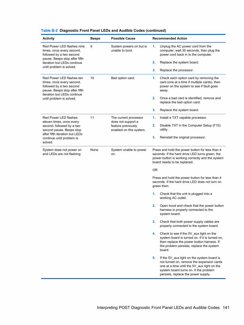
Table B-2 Diagnostic Front Panel LEDs and Audible Codes (continued)
Activity Beeps Possible Cause Recommended Action
Red Power LED flashes ninetimes, once every second,followed by a two secondpause. Beeps stop after fifthiteration but LEDs continueuntil problem is solved.
9 System powers on but isunable to boot.
1. Unplug the AC power cord from thecomputer, wait 30 seconds, then plug thepower cord back in to the computer.
2. Replace the system board.
3. Replace the processor.
Red Power LED flashes tentimes, once every second,followed by a two secondpause. Beeps stop after fifthiteration but LEDs continueuntil problem is solved.
10 Bad option card. 1. Check each option card by removing thecard (one at a time if multiple cards), thenpower on the system to see if fault goesaway.
2. Once a bad card is identified, remove andreplace the bad option card.
3. Replace the system board.
Red Power LED flasheseleven times, once everysecond, followed by a twosecond pause. Beeps stopafter fifth iteration but LEDscontinue until problem issolved.
11 The current processordoes not support afeature previouslyenabled on this system.
1. Install a TXT capable processor.
2. Disable TXT in the Computer Setup (F10)utility.
3. Reinstall the original processor.
System does not power onand LEDs are not flashing.
None System unable to poweron.
Press and hold the power button for less than 4seconds. If the hard drive LED turns green, thepower button is working correctly and the systemboard needs to be replaced.
OR
Press and hold the power button for less than 4seconds. If the hard drive LED does not turn ongreen then:
1. Check that the unit is plugged into aworking AC outlet.
2. Open hood and check that the power buttonharness is properly connected to thesystem board.
3. Check that both power supply cables areproperly connected to the system board.
4. Check to see if the 5V_aux light on thesystem board is turned on. If it is turned on,then replace the power button harness. Ifthe problem persists, replace the systemboard.
5. If the 5V_aux light on the system board isnot turned on, remove the expansion cardsone at a time until the 5V_aux light on thesystem board turns on. It the problempersists, replace the power supply.
Interpreting POST Diagnostic Front Panel LEDs and Audible Codes 141

C Connector Pin Assignments
This appendix contains the pin assignments for many computer and workstation connectors. Some ofthese connectors may not be used on the product being serviced.
Ethernet BNC
Connector and Icon Pin Signal
1
2
Data
Ground
USB
Connector and Icon Pin Signal
1
2
3
4
+5 VDC
- Data
+ Data
Ground
Microphone
Connector and Icon (1/8” miniphone) Pin Signal
1 (Tip)
2 (Ring)
3 (Shield)
Audio_left
Audio_Right
Ground
142 Appendix C Connector Pin Assignments

Headphone
Connector and Icon (1/8” miniphone) Pin Signal
1 (Tip)
2 (Ring)
3 (Shield)
Audio_left
Power_Right
Ground
Line-in Audio
Connector and Icon (1/8” miniphone) Pin Signal
1 (Tip)
2 (Ring)
3 (Shield)
Audio_In_Left
Audio_In_Right
Ground
Line-out Audio
Connector and Icon (1/8” miniphone) Pin Signal
1 (Tip)
2 (Ring)
3 (Shield)
Audio_Out_Left
Audio_Out_Right
Ground
Headphone 143

D Power Cord Set Requirements
The power supplies on some computers have external power switches. The voltage select switchfeature on the computer permits it to operate from any line voltage between 100-120 or 220-240 voltsAC. Power supplies on those computers that do not have external power switches are equipped withinternal switches that sense the incoming voltage and automatically switch to the proper voltage.
The power cord set received with the computer meets the requirements for use in the country whereyou purchased the equipment.
Power cord sets for use in other countries must meet the requirements of the country where you usethe computer.
General RequirementsThe requirements listed below are applicable to all countries:
1. The power cord must be approved by an acceptable accredited agency responsible forevaluation in the country where the power cord set will be installed.
2. The power cord set must have a minimum current capacity of 10A (7A Japan only) and anominal voltage rating of 125 or 250 volts AC, as required by each country’s power system.
3. The diameter of the wire must be a minimum of 0.75 mm2 or 18AWG, and the length of the cordmust be between 1.8 m (6 feet) and 3.6 m (12 feet).
The power cord should be routed so that it is not likely to be walked on or pinched by items placedupon it or against it. Particular attention should be paid to the plug, electrical outlet, and the pointwhere the cord exits from the product.
WARNING! Do not operate this product with a damaged power cord set. If the power cord set isdamaged in any manner, replace it immediately.
Japanese Power Cord RequirementsFor use in Japan, use only the power cord received with this product.
CAUTION: Do not use the power cord received with this product on any other products.
144 Appendix D Power Cord Set Requirements

Country-Specific RequirementsAdditional requirements specific to a country are shown in parentheses and explained below.
Country Accrediting Agency Country Accrediting Agency
Australia (1)
Austria (1)
Belgium (1)
Canada (2)
EANSW
OVE
CEBC
CSA
Italy (1)
Japan (3)
Norway (1)
Sweden (1)
IMQ
METI
NEMKO
SEMKO
Denmark (1)
Finland (1)
France (1)
Germany (1)
DEMKO
SETI
UTE
VDE
Switzerland (1)
United Kingdom (1)
United States (2)
SEV
BSI
UL
1. The flexible cord must be Type HO5VV-F, 3-conductor, 0.75mm2 conductor size. Power cord set fittings (appliancecoupler and wall plug) must bear the certification mark of the agency responsible for evaluation in the country where itwill be used.
2. The flexible cord must be Type SVT or equivalent, No. 18 AWG, 3-conductor. The wall plug must be a two-polegrounding type with a NEMA 5-15P (15A, 125V) or NEMA 6-15P (15A, 250V) configuration.
3. Appliance coupler, flexible cord, and wall plug must bear a “T” mark and registration number in accordance with theJapanese Dentori Law. Flexible cord must be Type VCT or VCTF, 3-conductor, 0.75 mm2 conductor size. Wall plugmust be a two-pole grounding type with a Japanese Industrial Standard C8303 (7A, 125V) configuration.
Country-Specific Requirements 145

E Specifications
All-in One ModelsTable E-1 Specifications
Desktop Dimensions (with stand)
Height
Width
Depth
17.22 in
21.64 in
8.09 in
43.75 cm
54.97 cm
20.54 cm
Approximate Weight
UMA
MXM
23.35 lbs
23.92 lbs
10.59 kg
10.85 kg
Temperature Range
Operating
Nonoperating
41° to 95°F
-22° to 149°F
5° to 35°C
-30° to 66°C
Relative Humidity (noncondensing)
Operating 15-80% at 79°F 15-80% at 26°C
Maximum Altitude (unpressurized)
Operating
Nonoperating
0 - 6,562 ft
0 - 15,000 ft
0 - 2000 m
4,572 m
Power Supply
Rated Voltage Range
Rated Line Frequency
100-240 V
50-60 Hz
100-240 V
50-60 Hz
Max Operating Power
UMA graphics
MXM graphics
<150 W
<180 W
<150 W
<180 W
Idle Operating Power Integrated graphics: 30 W Integrated graphics: 30 W
146 Appendix E Specifications
Index
Aantenna
spare part number 31antenna, spare part number 38audible codes 139audio problems 111
Bbattery
disposal 26beep codes 139booting options
Full Boot 131Quick Boot 131
Ccable connector
removing 78cable pinouts
SATA data 18cable routing
removing 91cables
antenna 31, 38converter 31, 39display panel 30, 38hard drive 31, 38LVDS 31, 39optical drive 31, 39power button/LED 31, 39spare part numbers 30touch controller 30, 39TV tuner 31TV tuner connector 38webcam 30, 38
cautionsAC power 20cables 25electrostatic discharge 20
keyboard cleaning 24keyboard keys 24
CD-ROM or DVD problems 123cleaning
computer 23mouse 25safety precautions 23
componentsfront 3rear 5side 4
computer cleaning 23connector pin assignments 142converter board
removing 52spare part number 28, 38
converter cablespare part number 31, 39
country power cord setrequirements 145
Customer Support 92, 130
Ddiskette problems 99display panel
removing 85spare part number 27, 38, 85
display panel cableremoving 83spare part number 30, 38
Eelectrostatic discharge (ESD) 20
preventing damage 21error
codes 131, 139messages 132
ethernetBNC pin assignments 142
Ffan
removing 72spare part number 31, 38
featuresoverview 1
flash drive problems 125flashing LEDs 139front bezel
removing 85spare part number 27, 38
front components 3front panel problems 126
Ggeneral problems 95graphics board
removing 70spare part number 28, 38
grounding methods 21
Hhard drive
proper handling 26removing 49SATA characteristics 18spare part number 29, 34
hard drive cablespare part number 31, 38
hard drive cage, spare partnumber 32, 38
hard drive connectorremoving 76
hard drive problems 102hard drive rubber grommet, spare
part number 32, 36hardware installation problems
116headphone pin assignments 143
Index 147

heat sinksremoving 66
helpful hints 93
IInternet access problems 126
KKensington Lock bracket
removing 74keyboard
cleaning 24keyboard problems 114keyboard, spare part number 32,
33, 34, 3634
Llabel, rear I/O, spare part
number 32, 38LEDs
blinking power 139blinking PS/2 keyboard 139
line-in audio pin assignments143
line-out audio pin assignments143
LVDS cable, spare part number31, 39
Mmass storage devices, spare part
numbers 29Media Card Reader problems
105memory cover
removing 43memory module
removing 45spare part number 29, 34
memory problems 121microphone pin assignments 142monitor problems 107mouse
cleaning 25mouse problems 114mouse, spare part number 32, 34
Nnetwork problems 117numeric error codes 132
Oopening the computer 40operating guidelines 23optical drive
removing 47spare part number 29, 34, 38
optical drive bezel, spare partnumber 32, 38
optical drive bracket, spare partnumber 32, 38
optical drive cablespare part number 31, 39
optical drive connectorremoving 76
optical drive dummy bezel, sparepart number 32, 38
optical drive problems 123overheating, prevention 23
PPOST error messages 131power button/LED cable
spare part number 31, 39power cord set requirements
country specific 145power problems 98power supply, spare part
number 32, 34power supply, specifications 146printer problems 113problems
audio 111CD-ROM or DVD 123diskette 99flash drive 125front panel 126general 95hard drive 102hardware installation 116Internet access 126keyboard 114Media Card Reader 105memory 121monitor 107mouse 114network 117power 98printer 113processor 122software 129
processorremoving 68spare part number 34, 36
processor problems 122
Rrear components 5rear cover
removing 41spare part number 27, 38
removal and replacementprocedures 76
All-in One chassis 40cable connector 78cable routing 91converter board 52display cable 83display panel 85fan 72front bezel 85graphics board 70hard drive 49hard drive connector 76heat sinks 66Kensington Lock bracket 74memory 45memory cover 43optical drive 47optical drive connector 76preparing to disassemble the
computer 40processor 68rear cover 41speakers 58stand 42system board 80system board cover 60thermal modules 66touch controller board 54TV tuner module 64VESA cover with Kensington
Lock bracket 74webcam module 56WLAN module 62
Ssafety and comfort 92safety precautions
cleaning 23
148 Index

SATAconnectors on system board
18data cable pinouts 18hard drive characteristics 18
screws, correct size 25service considerations 25side components 4software
problems 129servicing computer 25
spare part numbertamper-resistent wrench 25Torx T-15 screwdriver 25
speakersremoving 58spare part number 31, 38
specificationscomputer 146
standremoving 42spare part number 27, 38
static electricity 20system board
removing 80SATA connectors 18spare part number 27, 37
system board coverremoving 60
Ttamper-proof screws
tool 25temperature control 23thermal module
spare part number 31, 38thermal modules
removing 66thermal pad
spare part number 32, 37thermal pad, spare part number
37tools, servicing 25Torx T15 screwdriver 25touch controller board
removing 54spare part number 28, 38
touch controller cablespare part number 30, 39
TV tunerremoving 64spare part number 28, 34
TV tuner connectorspare part number 31, 38
UUSB pin assignments 142
Vventilation, proper 23VESA cover with Kensington Lock
bracketremoving 74
WWake-on-LAN feature 118webcam cable
spare part number 30, 38webcam module
removing 56spare part number 29, 38
WLAN moduleremoving 62spare part number 28, 34
Index 149