maintenance manual mm-0250 amboid rear differential carriergraphicvillage.org/meritor/mm0250.pdf ·...
TRANSCRIPT

Maintenance Manual MM-0250
Amboid Rear Differential CarrierRear/Rear Carrier on MT-40-143MA-N Tandem Drive AxlesRevised 08-10

Service Notes
Information contained in this publication was in effect at the time the publication was approved for printing and is subject to change without notice or liability. Meritor Heavy Vehicle Systems, LLC, reserves the right to revise the information presented or to discontinue the production of parts described at any time.
Meritor Maintenance Manual MM-0250 (Revised 08-10)
About This ManualThis manual provides instructions for the Meritor MT-40-143MA-N amboid rear/rear tandem axle.
Before You Begin1. Read and understand all instructions and procedures before
you begin to service components.
2. Read and observe all Warning and Caution hazard alert messages in this publication. They provide information that can help prevent serious personal injury, damage to components, or both.
3. Follow your company’s maintenance and service, installation, and diagnostics guidelines.
4. Use special tools when required to help avoid serious personal injury and damage to components.
Hazard Alert Messages and Torque Symbols
WARNINGA Warning alerts you to an instruction or procedure that you must follow exactly to avoid serious personal injury and damage to components.
CAUTIONA Caution alerts you to an instruction or procedure that you must follow exactly to avoid damage to components.
@ This symbol alerts you to tighten fasteners to a specified torque value.
How to Obtain Additional Maintenance and Service Information
On the WebVisit Literature on Demand at meritor.com to access and order product, service, aftermarket, and warranty literature for Meritor’s truck, trailer and specialty vehicle components.
Literature on Demand (LODonDVD)The LODonDVD contains product, service and warranty information for Meritor components. To order the DVD, visit Literature on Demand at meritor.com and specify TP-0742.
How to Obtain Tools and Supplies Specified in This ManualCall Meritor’s Commercial Vehicle Aftermarket at 888-725-9355 to obtain Meritor tools and supplies.

pg. pg.
Contents
1 Section 1: Exploded Views 2 Section 2: Introduction
OverviewAmboid Rear Differential Carrier
3 Section 3: DisassemblyRemovalDifferential Carrier from the Axle Housing
11 Section 4: Prepare Parts for AssemblyCleanClean Ground and Polished PartsClean Rough PartsClean Axle AssembliesClean, Dry and Inspect PartsDry Parts After CleaningCorrosion ProtectionPrevent Corrosion on Cleaned Parts
12 InspectionInspect Parts
13 RepairRepair or Replace the Parts
14 Repair Welding on Axle HousingsPrepare Parts for AssemblyPrepare the Axle
15 RemovalFasteners Secured with Adhesive
16 InstallationFastenersApplying Adhesive and Silicone Gasket MaterialMeritor Specification 2297-P-3994, Loctite® 680
Adhesive or Equivalent in the Bearing Bores Differential17 Applications
Loctite® 5699 Silicone Gasket Material, or Equivalent18 Identification
Gear Sets
20 Section 5: Assembly and InstallationAssemblyDrive PinionAdjusting the Drive Pinion Depth and Tapered Roller
Bearing Preload22 Determine the Correct Shim Pack Thickness
Installation23 Adjustment
Adjusting Pinion Bearing Preload24 Installing Multiple Lip Seals (MLS) on all Yoke Types26 Assembly
Assemble the Main Differential and Ring Gear Assembly30 Adjustment32 Ring Gear Tooth Contact Pattern, Backlash33 Specifications
Check Gear Set Tooth Contact Patterns, Backlash37 Installation
Install the Differential Carrier into the Axle Housing38 Install the Axle Shafts
39 Section 6: Lubrication41 Section 7: Specifications
Fasteners
46 Section 8: Vehicle Towing InstructionsRemovalBefore Towing or Drive-Away
47 InstallationAfter Towing or Drive-Away
48 Section 9: Special ToolsSpecial ToolsHow to Make a Yoke Bar
49 Carrier Repair Stand Specifications50 Specifications
Multiple Lip Seals (MLS) and Seal Drivers
1 Exploded Views
1 Exploded Views
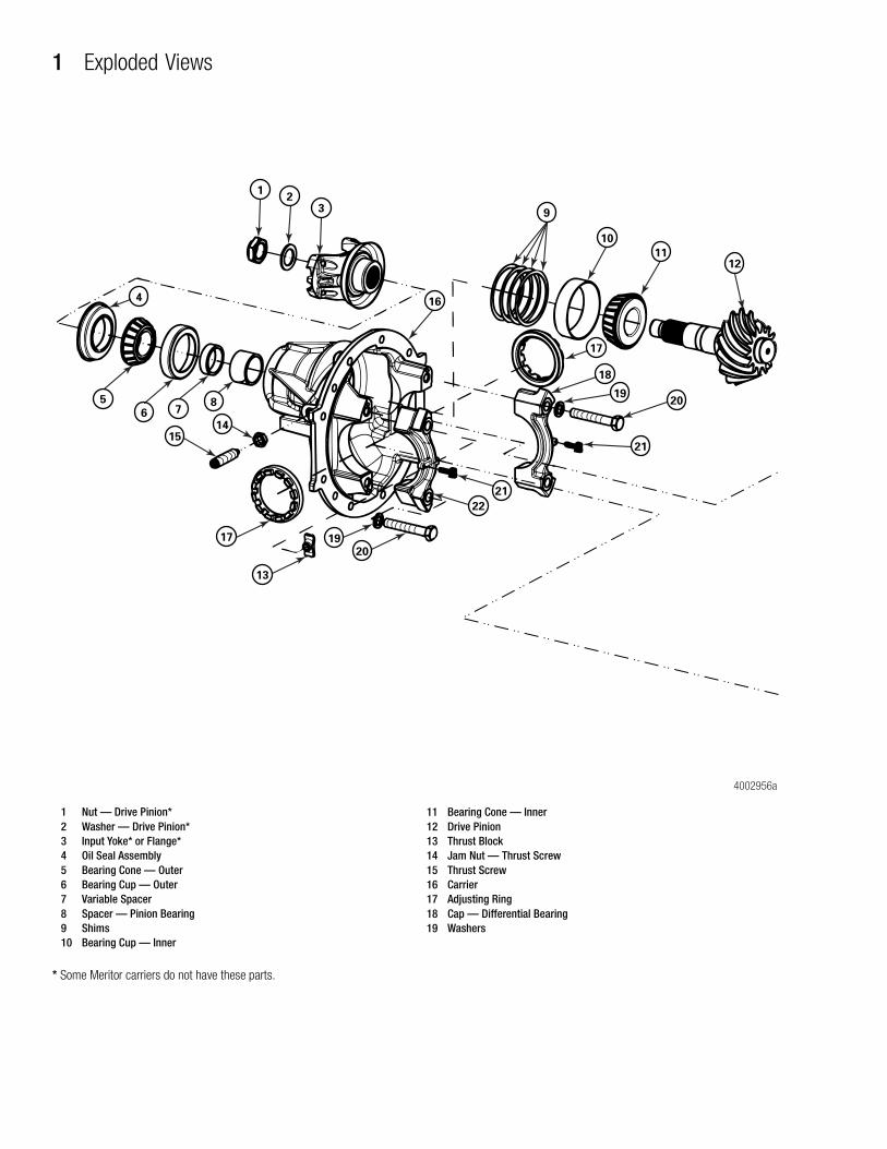
* Some Meritor carriers do not have these parts.
Figure 1.1
1 Nut — Drive Pinion*2 Washer — Drive Pinion*3 Input Yoke* or Flange*4 Oil Seal Assembly5 Bearing Cone — Outer6 Bearing Cup — Outer7 Variable Spacer8 Spacer — Pinion Bearing9 Shims10 Bearing Cup — Inner
11 Bearing Cone — Inner12 Drive Pinion13 Thrust Block14 Jam Nut — Thrust Screw15 Thrust Screw16 Carrier17 Adjusting Ring18 Cap — Differential Bearing19 Washers
4002956a
12
3 9
10
16
18
19
17
21
22
4
5
6 78
1415
17
13
1920
20
21
1112

1 Exploded Views
1Meritor Maintenance Manual MM-0250 (Revised 08-10)
* Some Meritor carriers do not have these parts.
Figure 1.2
20 Capscrew — Differential Bearing Cup21 Cotter Pin22 Cap — Differential Bearing Carrier23 Bearing Cup — Differential24 Bearing Cone — Differential25 Nuts* — Gear to Case26 Washer — Gear to Case27 Case — Differential Flange Half28 Ring Gear, Pinion Drive Gear29 Bolts — Gear to Case
30 Thrust Washers — Differential Side Gear31 Side Gear — Differential32 Pinions — Differential33 Thrust Washers — Differential Pinion34 Spider — Differential35 Case — Differential Plain Half36 Washer — Differential Case37 Bolts — Differential Case
4002956b
23
24
27
26
25
28
2933
32
34
30
31
33
32 31
30
35
24
23
36
37

2 Introduction
2 Meritor Maintenance Manual MM-0250 (Revised 08-10)
2 IntroductionOverview
Amboid Rear Differential CarrierThe Meritor single-reduction Amboid rear differential carrier is used on MT-40-143MA-N tandem drive axles. The Amboid design minimizes driveline angle configuration and places the drive pinion above the centerline, which helps to reduce vibration during operation.
The carrier is front-mounted into the axle housing and has an Amboid drive pinion and ring gear set.
All bearings in the carrier are tapered roller bearings.
When the carrier operates, there is normal differential action between the wheels at all times.
Figure 2.1
TAPEREDROLLERBEARINGS
TAPEREDROLLERBEARING
BEVELDIFFERENTIALGEARS
AXLEHOUSING
TAPEREDROLLER
BEARING
CARRIER
AMBOIDDRIVE
PINIONAND RING
GEAR
4000177b

3 Disassembly
3Meritor Maintenance Manual MM-0250 (Revised 08-10)
3 DisassemblyHazard Alert MessagesRead and observe all Caution and Warning safety alerts below and those that precede instructions or procedures you will perform.
WARNINGTo prevent serious eye injury, always wear safe eye protection when you perform vehicle maintenance or service.
Removal
Differential Carrier from the Axle Housing
WARNINGPark the vehicle on a level surface. Block the wheels to prevent the vehicle from moving. Support the vehicle with safety stands. Do not work under a vehicle supported only by jacks. Jacks can slip and fall over. Serious personal injury and damage to components can result.
1. Park the vehicle on a level surface and block the wheels to prevent the vehicle from moving.
2. Raise the end of the vehicle where the axle is mounted. Use a jack or other lifting tool, and place safety stands under each side of the axle.
3. Place jackstands under each spring seat of the axle to hold the vehicle in the raised position. Figure 3.1.
4. Remove the plug from the bottom of the axle housing and drain the lubricant from the assembly.
Figure 3.1
5. Disconnect the driveline universal joint from the pinion input yoke or flange on the carrier. Figure 3.2.
Figure 3.2
Figure 3.1
SAFETYSTANDS
1002983a
Figure 3.2
1 FULL-ROUND BEARING CUPS2 END YOKE3 YOKE SADDLE4 WELD YOKE5 BEARING STRAP6 CAPSCREWS7 EASY-SERVICE™ BEARING CUPS8 U-JOINT CROSS9 SLIP YOKE10 CAPSCREWS11 END YOKE12 WELD YOKE13 SLIP YOKE
14 U-JOINT CROSS15 CAPSCREWS16 END YOKE17 WELD YOKE18 SLIP YOKE19 U-JOINT CROSS20 CAPSCREWS21 END YOKE22 SLIP YOKE23 TUBING24 U-JOINT CROSS25 WELD YOKE
12
13
11
14
10
7
8
6
45
1
2
3
9
16
15
17
18
19
1002984b
EASY SERVICETM
WING SERIESPERMALUBETM
FULL-ROUND
“RPL” SERIES,PERMALUBETM
2324
22
2021
25

3 Disassembly
4 Meritor Maintenance Manual MM-0250 (Revised 08-10)
6. Remove the capscrews and washers or stud nuts and washers, if equipped, from the flanges of both axle shafts.
7. Loosen the tapered dowels, if equipped, in the axle flanges of both axle shafts using one of the following methods.
Brass Drift Method
WARNINGDo not strike the round driving lugs on the flange of an axle shaft. Pieces can break off and cause serious personal injury.
NOTE: You can use a 1-1/2-inch (38 mm) diameter brass hammer as a drift.
1. Hold a 1-1/2-inch (38 mm) diameter brass drift against the center of the axle shaft, inside the round driving lugs. Figure 3.3.
Figure 3.3
2. Use a 5-6 lb (2-3 kg) hammer to strike the end of the drift to loosen the axle shaft and tapered dowels.
3. Mark each axle shaft to identify it before you remove it from the axle assembly.
4. Remove the tapered dowels. Separate the axle shafts from the main axle hub assembly. Figure 3.4.
Figure 3.4
5. Install a cover over the open end of each axle assembly hub where an axle shaft was removed.
Air Hammer Vibration Method
CAUTIONDo not use a chisel or wedge to loosen the axle shaft and tapered dowels, which can damage the axle shaft, gasket and seal, and axle hub.
1. Use a round hammer bit and an air hammer to loosen the tapered dowels and axle shaft.
2. Place the round hammer bit against the axle shaft betweenthe hub studs. Operate the air hammer at alternate locations between the studs to loosen the tapered dowels and axle shaft from the hub. Figure 3.5.
Figure 3.5
Figure 3.3
BRASSHAMMER
DRIVINGLUGS 1003117b
Figure 3.4
Figure 3.5
AXLESHAFT
(FLANGE)
WASHER SHAFTHUBAXLE
GASKET STUD
STUDNUT
WASHER
TAPEREDDOWEL
CAPSCREW
1002986a
ROUND HAMMER BITBETWEEN HUB STUDS
1002987a

3 Disassembly
5Meritor Maintenance Manual MM-0250 (Revised 08-10)
3. Mark each axle shaft to identify it before you remove it from the axle assembly.
4. Remove the tapered dowels. Separate the axle shaft from the main axle hub assembly. Figure 3.4.
5. Install a cover over the open end of each axle assembly hub where an axle shaft was removed.
Carrier from the Axle
1. Place a hydraulic roller jack under the differential carrier to support the assembly. Figure 3.6.
Figure 3.6
2. Remove all but the top two carrier-to-housing capscrews or stud nuts and washers.
3. Loosen the top two carrier-to-housing fasteners, but leave them attached to the assembly. The fasteners will hold the carrier in the housing.
WARNINGUse a brass or synthetic mallet for assembly and disassembly procedures. Do not hit steel parts with a steel hammer. Pieces of a part can break off. Serious personal injury and damage to components can result.
4. Loosen the differential carrier in the axle housing. Use a leather mallet to hit the mounting flange of the carrier at several points.
5. After the carrier is loosened, remove the top two fasteners.
6. Carefully remove the carrier from the axle housing using the hydraulic roller jack. Use a pry bar that has a round end to help remove the carrier from the housing. Take care that you don’t damage the carrier or housing flange with the pry bar.
NOTE: A carrier stand is available from SPX Kent-Moore. To obtain this tool, refer to the Service Notes page on the front inside cover of this manual.
7. Use a lifting tool to lift the differential carrier by the input yoke or flange. Do not lift the carrier by hand. Place the assembly in a carrier stand. Figure 3.7. Refer to Section 9, Special Tools, to build a stand.
Figure 3.7
Differential and Ring Gear from the Carrier
1. Before you begin service procedures on the differential carrier, inspect the gear set for damage.
� If the gear set isn’t damaged: You can reuse thegear set.
� If the gear set is damaged: Replace it with a new gear set.
2. Measure and record gear set backlash. Figure 3.8. Refer to Step 1 through Step 4 under Ring Gear Tooth Contact Pattern, Backlash in Section 5 for instructions. Adjust backlash to the original dimension when you install the gear set into the carrier during assembly procedures.
Figure 3.6
WOODBLOCK
ROLLERJACK 1002709b
Figure 3.7
REPAIRSTAND
DIFFERENTIALCARRIER
1002710c

3 Disassembly
6 Meritor Maintenance Manual MM-0250 (Revised 08-10)
Figure 3.8
3. Loosen the jam nut on the thrust screw. Figure 3.9.
Figure 3.9
4. Rotate the differential carrier in the repair stand until the ring gear is at the TOP of the assembly.
5. Use a center punch and hammer to mark one carrier leg and bearing cap to correctly match the parts during carrier assembly. Figure 3.10.
Figure 3.10
6. Remove the cotter pins that secure the bearing adjusting rings in position. Use a small drift and hammer to remove the pins. Figure 3.11.
Figure 3.11
7. Remove the two capscrews and washers that secure the two bearing caps onto the carrier. Figure 3.12.
Figure 3.8
Figure 3.9
DIAL
INDICATOR
1002991a
4000166a
Figure 3.10
Figure 3.11
BEARINGCAP
CARRIERLEG
1002994a
MATCHMARKS
REMOVINGCOTTER
PIN
1002995b

3 Disassembly
7Meritor Maintenance Manual MM-0250 (Revised 08-10)
Figure 3.12
8. Remove the bearing caps and bearing adjusting rings from the carrier. Figure 3.13.
Figure 3.13
9. Use a lifting strap to lift the main differential and ring gear assembly from the carrier. Place the assembly onto a work bench. Figure 3.14.
Figure 3.14
10. Remove the thrust screw, jam nut and thrust block from the differential carrier. Figure 3.9 and Figure 3.15.
Figure 3.15
Disassemble the Differential and Ring Gear Assembly
NOTE: The marks on the plain and flange case halves will help you to match them correctly when you assemble the carrier.
1. If the match marks on the case halves of the differential assembly are not visible, mark each case half with a center punch and hammer. Figure 3.16.
Figure 3.16
2. Remove the capscrews and washers from the case halves.
Figure 3.12
Figure 3.13
Figure 3.14
BEARINGCAP
1002996a
BEARINGCAP BEARING
ADJUSTINGRING
1002997b
1002998a
Figure 3.15
Figure 3.16
THRUSTSCREW AND
JAM NUT
1002993d
THRUSTBLOCK
MATCH
MARKS1002999b

3 Disassembly
8 Meritor Maintenance Manual MM-0250 (Revised 08-10)
WARNINGUse a brass or synthetic mallet for assembly and disassembly procedures. Do not hit steel parts with a steel hammer. Pieces of a part can break off. Serious personal injury and damage to components can result.
3. Separate the case halves. If necessary, use a brass, plastic or leather mallet to loosen the parts.
4. Remove the differential spider, four pinion gears, two side gears and six thrust washers from the inside of the case halves. Figure 3.17.
� If you need to replace the ring gear: Remove the bolts, nuts and washers that secure the gear to the flange case half.
Figure 3.17
WARNINGObserve all warnings and cautions provided by the press manufacturer to avoid damage to components and serious personal injury.
5. Use a press to separate the case half and ring gear. Support the assembly under the ring gear with metal or wood blocks. Press the case half through the gear. Figure 3.18.
� If you need to replace the differential bearings: Use a bearing puller or press to remove the bearing cones from the case halves. Figure 3.19.
Figure 3.18
Figure 3.19
Drive Pinion from the Carrier
1. Fasten a flange bar to the input yoke or flange. When you remove the nut, the bar will hold the drive pinion in position. Refer to Section 9 for instructions to make a yoke bar. Figure 3.20.
2. Remove the nut and washer, if equipped, from the drive pinion. Figure 3.20.
3. Remove the yoke or flange bar.
Figure 3.17
THRUSTWASHER
SIDEGEAR
SPIDER,PINIONSANDTHRUSTWASHERS
1003000a
Figure 3.18
Figure 3.19
CASEHALF
PRESS
PLATE
1003002c
SUPPORTS
1002750a
PULLER
PRESS

3 Disassembly
9Meritor Maintenance Manual MM-0250 (Revised 08-10)
Figure 3.20
CAUTIONIf the yoke and flange are difficult to remove from the drive pinion during disassembly, use a puller. Do not use a hammer or mallet, which can damage components and affect driveline alignment and end play.
4. Remove the yoke or flange from the drive pinion. If the yoke or flange is tight on the pinion, use a puller. Figure 3.21.
Figure 3.21
NOTE: Always use a new oil seal during reassembly. Don’t reuse a seal that’s been removed.
5. Use appropriate prying tools to remove the unitized oil seal from the carrier. Place the blades of the prying tools under the flange to remove the oil seal. Figure 3.22.
Figure 3.22
WARNINGObserve all warnings and cautions provided by the press manufacturer to avoid damage to components and serious personal injury.
6. Place the carrier assembly in a press with the threaded end of the pinion shaft pointing UP. Figure 3.23.
Figure 3.23
7. Press the pinion shaft out of the outer bearing cone. Do not let the pinion shaft drop to the ground after being pressed out. Figure 3.23.
Figure 3.20
Figure 3.21
4000167a
FLANGE/YOKE
BAR
1003348b
YOKEPULLER
FLANGEPULLER
Figure 3.22
Figure 3.23
4000168a
4000169a

3 Disassembly
10 Meritor Maintenance Manual MM-0250 (Revised 08-10)
8. Remove the outer bearing cone from the carrier.
� If you need to replace the pinion bearings: Use a suitable puller to remove the inner and outer bearing cups from the carrier.
9. Remove the shims from the carrier.
� If the shims are in good condition: Keep the shims together for use when the carrier is assembled.
� If the shims are to be discarded because of damage: First measure the total thickness of the pack. Make a note of the dimension. You will need the dimension to calculate the depth of the drive pinion in the carrier when the gear set is installed.
10. Remove the bearing spacer and variable spacer from the pinion shaft. Figure 3.24.
� If you need to replace the pinion bearings: Use a press or bearing puller to remove the inner bearing cone from the drive pinion. The puller must fit under the inner race of the cone to remove the cone correctly without damage. Figure 3.25.
Figure 3.24
Figure 3.25
Figure 3.24
4000170a
SPACERS
Figure 3.25
SUPPORTS
INNERBEARING
CONE
PRESSDRIVEPINION
BEARINGPULLER
1003012d

4 Prepare Parts for Assembly
11Meritor Maintenance Manual MM-0250 (Revised 08-10)
4 Prepare Parts for AssemblyHazard Alert MessagesRead and observe all Caution and Warning safety alerts below and those that precede instructions or procedures you will perform.
WARNINGTo prevent serious eye injury, always wear safe eye protection when you perform vehicle maintenance or service.
Solvent cleaners can be flammable, poisonous and cause burns. Examples of solvent cleaners are carbon tetrachloride, and emulsion-type and petroleum-base cleaners. Read the manufacturer’s instructions before using a solvent cleaner, then carefully follow the instructions. Also follow the procedures below.
� Wear safe eye protection.
� Wear clothing that protects your skin.
� Work in a well-ventilated area.
� Do not use gasoline, or solvents that contain gasoline. Gasoline can explode.
� You must use hot solution tanks or alkaline solutions correctly. Read the manufacturer’s instructions before using hot solution tanks and alkaline solutions. Then carefully follow the instructions.
Clean
Clean Ground and Polished Parts1. Use a cleaning solvent to clean ground or polished parts or
surfaces. Kerosene or diesel fuel oil can be used for this purpose. DO NOT USE GASOLINE.
2. Use a tool with a flat blade if required, to remove sealant material from parts. Be careful not to damage the polished or smooth surfaces.
CAUTIONDo not use hot solution tanks or water and alkaline solutions to clean ground or polished parts. Damage to parts can result.
3. Do not clean ground or polished parts with water or steam. Do not immerse ground or polished parts in a hot solution tank or use strong alkaline solutions for cleaning, or the smooth sealing surface may be damaged.
Clean Rough Parts1. Clean rough parts with the same method as cleaning ground
and polished parts.
2. Rough parts can be cleaned in hot solution tanks with a weak or diluted alkaline solution.
3. Parts must remain in hot solution tanks until heated and completely cleaned.
4. Parts must be washed with water until all traces of the alkaline solution are removed.
Clean Axle Assemblies1. A complete axle assembly can be steam cleaned on the
outside to remove dirt.
2. Before the axle is steam cleaned, close or place a cover over all openings in the axle assembly. Examples of openings are breathers or vents in air chambers.
Clean, Dry and Inspect Parts
Dry Parts After Cleaning1. Parts must be dried immediately after cleaning and washing.
2. Dry the parts using soft, clean paper or cloth rags.
CAUTIONDamage to bearings can result when they are rotated and dried with compressed air.
3. Except for bearings, parts can be dried with compressed air.
Corrosion Protection
Prevent Corrosion on Cleaned Parts1. Apply axle lubricant to cleaned and dried parts that are not
damaged and are to be assembled.
2. To store parts, apply a special material that prevents corrosion to all surfaces. Wrap cleaned parts in a special paper that will protect the parts from moisture and prevent corrosion.

4 Prepare Parts for Assembly
12 Meritor Maintenance Manual MM-0250 (Revised 08-10)
Inspection
Inspect PartsIt is very important to inspect all parts carefully and completely before the axle or carrier is assembled. Check all parts for wear and replace damaged parts.
1. Inspect the cup, cone, rollers and cage of all tapered roller bearings in the assembly. If any of the following conditions exist, replace the bearing.
� The center of the large-diameter end of the rollers is worn level with or below the outer surface. Figure 4.1.
� The radius at the large-diameter end of the rollers is worn to a sharp edge. Figure 4.1.
� There is a visible roller groove in the cup or cone inner race surfaces. The groove can be seen at the small- or large-diameter end of both parts. Figure 4.2.
� There are deep cracks or breaks in the cup, cone inner race or roller surfaces. Figure 4.2.
� There are bright wear marks on the outer surface of the roller cage. Figure 4.3.
� There is damage on the rollers and on the surfaces of the cup and cone inner race that touch the rollers. Figure 4.4.
� There is damage on the cup and cone inner race surfaces that touch the rollers. Figure 4.5.
Figure 4.1
Figure 4.2
Figure 4.3
Figure 4.4
Figure 4.1
1003017b
WORN RADIUS
WORN SURFACE
Figure 4.2
Figure 4.3
Figure 4.4
1003018b
WEARGROOVES
CRACK
1003019aWEAR MARKS
1003020a
ETCHING AND PITTING

4 Prepare Parts for Assembly
13Meritor Maintenance Manual MM-0250 (Revised 08-10)
Figure 4.5
CAUTIONA drive pinion and ring gear is machined as a matched set. When you replace either a drive pinion or a ring gear, you must replace both parts as a matched set. Do not mix old and new parts. Damage to components can result.
2. Inspect pinions and gears for wear or damage. Replace gears that are worn or damaged.
CAUTIONA thrust washer, differential side gear and pinion gear are machined as a matched set. When you replace any of these parts, you must install a new matched set. Do not mix old and new parts. Damaged to components can result.
3. Inspect the following main differential assembly parts for wear or stress. Replace parts that are damaged. Figure 4.6.
� Inside surfaces of both case halves
� Both surfaces of all thrust washers
� The four trunnion ends of the spider
� Teeth and splines of both differential side gears
� Teeth and bore of all differential pinions
4. Inspect the axle shafts for wear and cracks at the flange, shaft and splines. Replace the axle shafts, if required.
Figure 4.6
Repair
Repair or Replace the Parts
NOTE: Threads must be without damage and clean so that accurate adjustments and correct torque values can be applied to fasteners and parts.
1. Replace any fastener if corners of the head are worn.
2. Replace the washers if damaged.
3. Replace the gaskets, oil seals or grease seals at the time of axle or carrier repair.
4. Clean the parts and apply new silicone gasket material where required when the axle or carrier is assembled. Figure 4.7.
Figure 4.7
Figure 4.5
1003021b
SPALLING AND FLAKING
Figure 4.6
Figure 4.7
Inspect inside surfaces.
Inspect.
SPIDER(CROSS)
Inspect.
Inspect.
PINION ANDTHRUST
WASHER
SIDE GEARAND THRUST
WASHER
1003022d
DIFFERENTIALCASE HALVES
DIFFERENTIALGEAR NEST ASSEMBLY
Remove siliconegasket from parts.
1003023a

4 Prepare Parts for Assembly
14 Meritor Maintenance Manual MM-0250 (Revised 08-10)
5. Remove nicks, marks and burrs from parts with machined or ground surfaces. Use a fine file, india stone, emery cloth or crocus cloth.
6. Clean and repair threads of fasteners and holes. Use a die, a tap of the correct size, or a fine file.
Repair Welding on Axle Housings
For Complete Welding Instructions on Meritor Drive Axle Housings
Refer to Maintenance Manual 8, Drive Axle Housings. To obtain this publication, refer to the Service Notes page on the front inside cover of this manual.
WARNINGWear safe clothing and eye protection when you use welding equipment. Welding equipment can burn you and cause serious personal injury. Follow the operating instructions and safety procedures recommended by the welding equipment manufacturers.
Axle weld locations and welding procedures must adhere to Meritor standards. Welding at locations other than those authorized by Meritor will void the warranty and can reduce axle beam fatigue life. Serious personal injury and damage to components can result.
Meritor permits drive axle housing assembly repair welding in the following locations only.
� Housing-to-cover weld joints
� Snorkel welds
� Housing seam welds between the suspension attaching brackets
� Bracket welding to the drive axle housing
Prepare Parts for Assembly
Prepare the Axle
WARNINGThe high temperature caused by the open flame from the cutting torch can ignite the oil in the axle housing and can cause serious personal injury.
1. Remove the oil drain plug from the bottom of the axle housing and drain the lubricant from the assembly.
CAUTIONRemove the differential carrier from the axle housing before you weld onto an axle. Do not weld onto an axle with the differential carrier installed. Electrical arcing and damage to components can result.
2. Remove the differential carrier from the axle housing. Refer to the correct Meritor carrier maintenance manual or the vehicle manufacturer’s instructions.
CAUTIONRemove the brake air chambers before you weld onto an axle. Do not expose a brake air chamber to more than 250°F (121°C). Damage to the air chamber can result.
3. Remove the wheel-end components and brake air chambers from the axle. Refer to the correct Meritor brake maintenance manual or the vehicle manufacturer’s instructions.
4. For housing-to-cover welds, clean the outside housing-to-cover weld area 2-3-inches (50.8-76.2 mm) past each end or side of the crack. Clean the inside area where the cover mates with the housing. Clean the area completely around the cover. Use a wire brush and a cleaning solvent that will remove dirt and grease from these areas. Figure 4.8.
Figure 4.8
Figure 4.8
Clean this area.4000309a

4 Prepare Parts for Assembly
15Meritor Maintenance Manual MM-0250 (Revised 08-10)
5. For suspension bracket welds, clean both lower and upper suspension brackets and the areas of the axle housing around each bracket. Use a wire brush and a cleaning solvent that will remove dirt and grease from these areas. Figure 4.9 and Figure 4.10.
Figure 4.9
Figure 4.10
WARNINGThe axle housing must be 70°F (21°C) or warmer before you weld onto the axle. Do not weld onto a cold axle or weld cold parts onto an axle. Cracks in the weld area, damage to components and serious personal injury can result.
6. Ensure that the axle housing temperature measures 70°F (21°C) or warmer.
� If the axle housing temperature measures less than 70°F (21°C): Store the axle in a heated room until the housing reaches the correct temperature.
7. Heat the damaged area to approximately 300°F (149°C) before you begin welding.
8. Use suitable weld wire electrodes when you weld. Suitable weld wire electrodes include either BS EN 499 – E 42 2 B 32 H5 or BS EN 440 – G 42 2 M GSi, American Welding Society equivalents E7018 and ER70S3, respectively.
9. For complete welding instruction, refer to Maintenance Manual 8. To obtain this publication, refer to the Service Notes page on the front inside cover of this manual.
Do Not Bend or Straighten a Damaged Drive Axle Housing
WARNINGReplace damaged or out-of-specification axle components. Do not bend, repair or recondition axle components by welding or heat-treating. A bent axle beam reduces axle strength, affects vehicle operation and voids Meritor’s warranty. Serious personal injury and damage to components can result.
Always replace a damaged drive axle housing. Do not bend or straighten a damaged housing, which can misalign or weaken it, and void the Meritor warranty.
Removal
Fasteners Secured with AdhesiveIf it’s difficult to remove fasteners secured with Dri-Loc, Meritor specification 2297-P-3994, Loctite 680 adhesive,or equivalent, use the following procedure.
CAUTIONWhen you remove fasteners secured with adhesive, slowly heat the fastener to 350°F (177°C). Do not exceed this temperature, or heat fasteners quickly. Damage to components can result.
1. Heat a fastener for three to five seconds only. Try to loosen the fastener with a wrench. Do not use an impact wrench or hit the fastener with a hammer.
2. Repeat Step 1 until you can remove the fastener.
Figure 4.9
Figure 4.10
Clean these areas.
4000310a
LOWER
BRACKET
Clean this area.
4000310a
Clean these areas.
UPPERBRACKET

4 Prepare Parts for Assembly
16 Meritor Maintenance Manual MM-0250 (Revised 08-10)
Installation
Fasteners
New Fasteners with Pre-Applied Adhesive
NOTE: No drying time is required for fasteners with pre-applied adhesive.
1. Use a wire brush to clean oil and dirt from threaded holes.
2. Install new fasteners with pre-applied adhesive to assemble parts. Do not apply adhesives or sealants to fasteners with pre-applied adhesive, or to fastener holes.
3. Tighten fasteners to the required torque value for that size fastener.
Original or Used Fasteners Using Meritor Liquid Adhesive 2297-P-3994, Loctite 680 Adhesive, or Equivalent
WARNINGTake care when you use Loctite adhesive to avoid serious personal injury. Read the manufacturer’s instructions before using this product. Follow the instructions carefully to prevent irritation to the eyes and skin.
1. Use a wire brush to clean the oil, dirt and old adhesive from all threads and threaded holes.
2. Apply four or five drops of Meritor liquid adhesive, Loctite 680 adhesive, or equivalent, inside each threaded hole or bore. Do not apply adhesive directly to fastener threads. Figure 4.11.
NOTE: There is no drying time required for Meritor specification 2297-C-7049 liquid adhesive, Loctite 680 adhesive, or equivalent.
3. Tighten the fasteners to the required torque value for thatsize fastener.
Figure 4.11
Applying Adhesive and Silicone Gasket Material
Meritor Specification 2297-P-3994, Loctite®
680 Adhesive, or Equivalent in the Bearing Bores Differential
NOTE: Use Meritor specification 2297-P-3994, Loctite 680 adhesive, or equivalent for all axles. To obtain this adhesive, refer to the Service Notes page on the front inside cover of this manual.
1. Clean the oil and dirt from the outer diameters of the bearing cups and bearing bores in the carrier and bearing caps. There is no special cleaning required.
2. Apply axle lubricant to the bearing cones and the inner diameters of the bearing cups of the main differential. Do not get oil on the outer diameter of the bearing cup and do not permit oil to drip on the bearing bores.
3. Apply a single continuous bead of adhesive to the bearing bores in the carrier and bearing caps. Apply the adhesive around the circumference of the smooth, ground surfaces only. Do not apply adhesive on the threaded areas. Figure 4.12.
Figure 4.11
1003025a
FOUR TOFIVE DROPS
ON BORETHREADS

4 Prepare Parts for Assembly
17Meritor Maintenance Manual MM-0250 (Revised 08-10)
Figure 4.12
NOTE: Meritor specification 2297-P-3994, Loctite 680 adhesive, or equivalent will dry in approximately two hours. Perform Step 4 and Step 5 within two hours from the time you apply the adhesive. If two hours have passed since application, clean the adhesive from the parts and apply new adhesive.
4. Install the main differential assembly, bearing cups and bearing caps into the carrier. Refer to Differential and Ring Gear Assembly and Figure 5.25 through Figure 5.28.
5. Adjust the preload of the differential bearings, backlash and tooth contact patterns of the gear set as required. Refer to Section 5.
Applications
Loctite® 5699 Silicone Gasket Material, or Equivalent� Loctite® 5699 silicone gasket material
� Loctite 18581 Ultra Grey adhesive/sealant
� Meritor gasket material/part number 2297-F-7052. To obtain this gasket material, refer to the Service Notes page on the front inside cover of this manual.
WARNINGWhen you apply some silicone gasket materials, a small amount of acid vapor is present. To prevent serious personal injury, ensure that the work area is well-ventilated. Read the manufacturer’s instructions before using a silicone gasket material, then carefully follow the instructions. If a silicone gasket material gets into your eyes, follow the manufacturer’s emergency procedures. Have your eyes checked by a physician as soon as possible.
NOTE: The following silicone gasket products or equivalent can be used for Meritor components:
1. Use a tool with a flat blade, if required, to remove all old gasket material from surfaces. Figure 4.13.
Figure 4.13
2. Use a cleaning solvent to clean the surfaces where you will apply silicone gasket material. Remove all oil, grease, dirt and moisture without damaging the mating surfaces. Figure 4.13.
3. Dry all surfaces.
Figure 4.12
ADHESIVE BEARINGCAP
CARRIERLEG
1003026a
Figure 4.13
1003027a
Remove oldsealant material.
HOUSING ANDCARRIER SHOWN

4 Prepare Parts for Assembly
18 Meritor Maintenance Manual MM-0250 (Revised 08-10)
CAUTIONApply silicone gasket material in a continuous 1/8-inch (3 mm) bead. If you use more than this amount, the gasket material can break off and plug lubrication passages. Damage to components can result.
4. Apply a 1/8-inch (3 mm) diameter continuous bead of the silicone gasket material around one surface. Also apply the gasket material around the edge of all fastener holes on that surface. Figure 4.14.
Figure 4.14
5. Assemble the components immediately to permit the silicone gasket material to compress evenly between the parts. Tighten fasteners to the required torque value for that size fastener. Refer to Table H in Section 7.
6. Wait 20 minutes before filling the assembly with the correct lubricant. Refer to Section 6.
Identification
Gear SetsRefer to the following examples for information on identifying gear sets with matched parts. Always check the match numbers to verify that the gear set you will install has matched parts. Figure 4.15.
Figure 4.15
Examples
Gear Set
Gear Set Tooth Combination Number
Figure 4.14
0.125" (3 MM)DIAMETER SILICONE
GASKET BEAD 1003028a
Figure 4.15
1 PART NUMBER, TOOTH COMBINATION NUMBER, GEAR SET MATCH NUMBER, PINION CONE VARIATION NUMBER
2 PART NUMBER, TOOTH COMBINATION NUMBER3 GEAR SET MATCH NUMBER, PINION CONE VARIATION NUMBER4 PART NUMBER, TOOTH COMBINATION NUMBER, GEAR SET MATCH
NUMBER5 PART NUMBER, TOOTH COMBINATION NUMBER GEAR SET MATCH
NUMBER
Part Number Location
Conventional ring gear
36786 On the front face or outer diameter
Conventional drive pinion
36787 At the end at threads
Gear Set TeethDrive Pinion Location
Ring GearLocation
5-37 = gear set has a five-tooth drive pinion and a 37-tooth ring gear
At the end at threads
On the front face or outer diameter
1003031b
ALTERNATE LOCATIONS

4 Prepare Parts for Assembly
19Meritor Maintenance Manual MM-0250 (Revised 08-10)
Gear Set Match Number
NOTE: Meritor drive pinions and ring gears are only available as matched sets. Each gear in a set has an alpha-numeric match number.
Pinion Cone Variation Number
NOTE: Don’t use the pinion cone variation number when you check for a matched gear set. Use this number when you adjust the pinion depth in the carrier. Refer to Section 5.
Match NumberDrive Pinion Location
Ring Gear Location
M29 At the end of thegear head
On the front face or outer diameter
Pinion Cone (PC) Variation Number
Drive Pinion Location
Ring Gear Location
PC+3 +2 +0.01 mm PC-5 –1 –0.02 mm
At the end of the pinon gear head
On the outer diameter

5 Assembly and Installation
20 Meritor Maintenance Manual MM-0250 (Revised 08-10)
5 Assembly and Installat ionHazard Alert MessagesRead and observe all Caution and Warning safety alerts below and those that precede instructions or procedures you will perform.
WARNINGTo prevent serious eye injury, always wear safe eye protection when you perform vehicle maintenance or service.
Observe all warnings and cautions provided by the press manufacturer to avoid damage to components and serious personal injury.
Assembly
Drive Pinion1. Place the drive pinion into a press with the gear head teeth
toward the bottom. Figure 5.1.
Figure 5.1
2. Press the inner bearing cone onto the shaft of the drive pinion, until the cone is flat against the gear head. Use a sleeve of the correct size against the bearing inner race.
3. Place the bearing spacer and variable spacer onto the pinion shaft against the inner bearing cone. Figure 5.2.
Figure 5.2
Adjusting the Drive Pinion Depth and Tapered Roller Bearing PreloadThe correct drive pinion depth adjustment and tapered bearing preload are critical to drive axle operation. Drive pinion teeth must mesh correctly with ring gear teeth, and preload on the tapered roller bearings must be correct.
The thickness of the pinion shim pack determines the depth of the drive pinion in the carrier case. Shims on the amboid carrier are located between the inner bearing cup and the carrier case. Figure 5.3.
Figure 5.3
When you add shims, the drive pinion head moves TOWARD the ring gear. When you remove shims, the drive pinion head moves AWAY from the ring gear.
Figure 5.1
SLEEVE
INNERBEARINGCONE
1003120b
Figure 5.2
Figure 5.3
4000170a
SPACERS
4005396a
SHIM LOCATIONS
SELECTIVESPACERLOCATIONS
CUP-TYPE DESIGN,AMBOID REAR
5 Assembly and Installation
21Meritor Maintenance Manual MM-0250 (Revised 08-10)
The thickness of the selective spacer between the outer bearing cone and the inner spacer determines the drive pinion bearing preload. You increase or decrease drive pinion bearing preload by installing a thicker or thinner selective spacer.
� Increase bearing preload = Install a thinner spacer
� Decrease bearing preload = Install a thicker spacer
If you change the depth of the drive pinion by adding or removing shims, you must also change the thickness of the spacer by the same amount to ensure that bearing preload remains unchanged.
Drive Pinion Cone (PC) Variation Numbers
Meritor assigns this number to a particular gear set after final machining. It represents the deviation from the designed nominal dimension and optimizes the tooth contact pattern. The PC number is hand-written on the ring gear.
PC Variation Number is a Plus (+)
A positive (+) number indicates the drive pinion must be positioned AWAY from the ring gear centerline to optimize the tooth contact pattern. Figure 5.4.
Figure 5.4
PC Variation Number is a Minus (−)
A negative (−) number designates that the drive pinion must be positioned CLOSER to the ring gear centerline to optimize the tooth contact pattern.
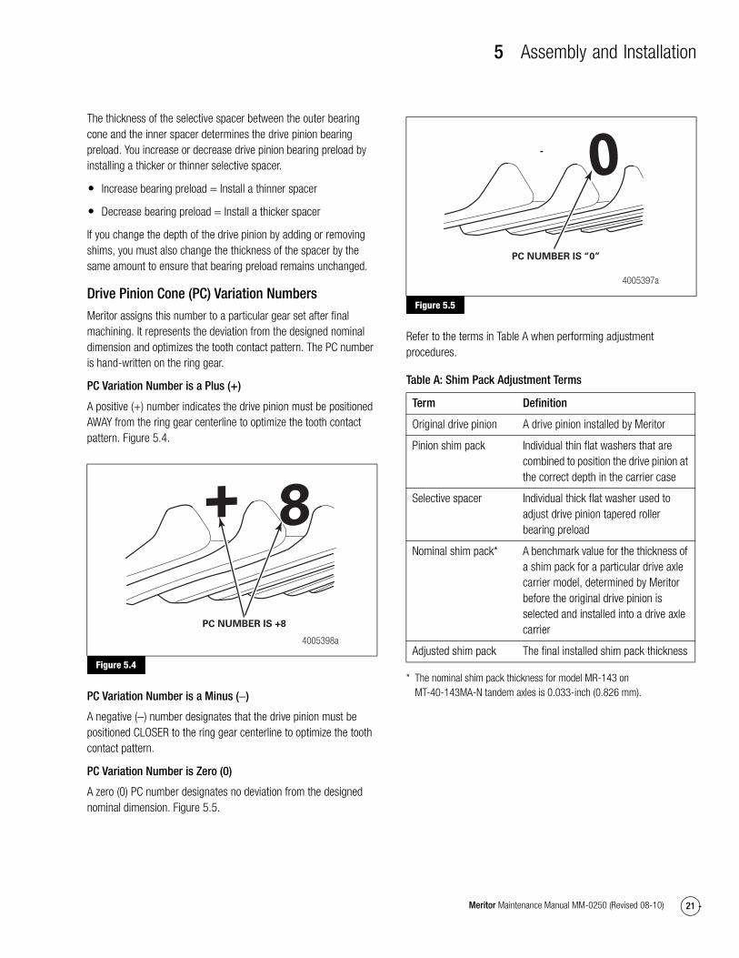
PC Variation Number is Zero (0)
A zero (0) PC number designates no deviation from the designed nominal dimension. Figure 5.5.
Figure 5.5
Refer to the terms in Table A when performing adjustment procedures.
Table A: Shim Pack Adjustment Terms
* The nominal shim pack thickness for model MR-143 on MT-40-143MA-N tandem axles is 0.033-inch (0.826 mm).
Figure 5.4
4005398a
PC NUMBER IS +8
Figure 5.5
Term Definition
Original drive pinion A drive pinion installed by Meritor
Pinion shim pack Individual thin flat washers that are combined to position the drive pinion at the correct depth in the carrier case
Selective spacer Individual thick flat washer used to adjust drive pinion tapered roller bearing preload
Nominal shim pack* A benchmark value for the thickness of a shim pack for a particular drive axle carrier model, determined by Meritor before the original drive pinion is selected and installed into a drive axle carrier
Adjusted shim pack The final installed shim pack thickness
4005397a
PC NUMBER IS “0”

5 Assembly and Installation
22 Meritor Maintenance Manual MM-0250 (Revised 08-10)
Determine the Correct Shim Pack ThicknessUse the applicable procedure to determine the correct shim pack thickness.
Installing the Original Drive Pinion and Ring Gear
1. Reinstall the original shim pack or a new shim pack of the same thickness as removed from the carrier.
� If the original shim pack thickness is unknown: Refer to the following steps.
A. If the PC variation number is readable on the original ring gear, refer to the Installing a New Drive Pinion and Ring Gear Set procedure in this section.
B. If the PC variation number is not readable, install the nominal shim pack thickness for the carrier.
2. Check the tooth contact pattern and adjust the shim pack as necessary to achieve the correct pattern.
Installing a New Drive Pinion and Ring Gear Set
1. Select the nominal shim pack thickness for the carrier.
2. Find the PC variation number for the drive pinion that’s written on the ring gear.
3. According to the PC variation number of the drive pinion, add or subtract the exact amount of shims to or from the shim pack to determine the adjusted shim pack for this carrier.
� If the PC variation number on the original drive pinion is plus (+): Subtract the PC variation number from the nominal shim pack thickness. Install this adjusted shim pack into the carrier.
Example: Model MR-143 has a nominal shim pack of 0.033-inch (0.826 mm). The new pinion PC variation number is +8 or 0.008-inch (0.203 mm). Subtract 0.008-inch (0.203 mm) from the nominal shim pack.
0.033″ − 0.008″ = 0.025″ New Shim Pack
� If the PC variation number on the original drive pinion is minus (−): Add the PC variation number to the nominal shim pack thickness. Install this adjusted shim pack intothe carrier.
Example: Model MR-143 has a nominal shim pack of 0.033-inch (0.826 mm). The new pinion PC variation number is −4 or 0.004-inch (0.102 mm). Subtract 0.004-inch (0.102 mm) from the nominal shim pack.
0.033″ − 0.004″ = 0.037″ New Shim Pack
� If the PC variation number on the drive pinion is zero (0): Install the nominal shim pack into the carrier.
4. Install the new drive pinion and ring gear, and check the tooth contact pattern.
Installation
Drive Pinion, Bearings and Shim Pack into the Carrier
NOTE: If a new drive pinion and ring gear set is installed, or if you have to adjust the depth of the drive pinion, calculate the thickness of the shim pack. Refer to Drive Pinion in this section.
1. Select the correct shim pack and install it into the carrier.
2. Apply axle lubricant to the pinion bearing cups and cones.
3. Position the inner bearing cup into the carrier. Figure 5.6. The bearing cup will hold the shims in place.
Figure 5.6
Figure 5.6
4000171b

5 Assembly and Installation
23Meritor Maintenance Manual MM-0250 (Revised 08-10)
WARNINGObserve all warnings and cautions provided by the press manufacturer to avoid damage to components and serious personal injury.
4. With a press or soft mallet and sleeve, drive the inner and outer bearing cups into the carrier. Use a sleeve that is the same size as the bearing cups. Press the bearing cups until they fit squarely in the bores.
5. Place the carrier into a press. Figure 5.7.
Figure 5.7
6. Install the pinion shaft assembly into the carrier. Seat the inner bearing cone fully against the inner bearing cup. Figure 5.7.
7. Support the pinion shaft with blocks of wood so that it remains fully seated in the carrier. Figure 5.7.
8. Install the outer bearing cone into the carrier. Figure 5.8.
Figure 5.8
9. Using a sleeve that is the same size as the bearing cone, press the bearing onto the pinion shaft until it is fully seated in the carrier. Figure 5.9.
Figure 5.9
Adjustment
Adjusting Pinion Bearing Preload
Table B: Specifications
CAUTIONDo not install tight-fitting yokes or flanges on the shafts using a hammer or mallet. A hammer or mallet will damage the yoke or flange.
NOTE: Use a press to install the yoke or flange.
1. Install the input yoke or flange, nut and washer, if equipped, onto the drive pinion. The yoke or flange must be seated against the outer bearing.
2. Fasten a yoke or flange bar to the input yoke or flange. The bar will hold the drive pinion in position when the nut is tightened.
3. Tighten the nut onto the drive pinion to the correct torque value. Refer to Table H in Section 7.
4. Remove the yoke or flange bar.
5. Attach a torque wrench onto the drive pinion nut. Rotate the drive pinion and read the value indicated on torque wrench.
Figure 5.7
Figure 5.8
4000172a
BLOCK OFWOODSUPPORTINGPINION
4000173a
Figure 5.9
New pinion bearings 20 to 50 lb-in (2.26 to 5.7 N�m)
Used pinion bearing in good condition
25 to 40 lb-in (2.8 to 4.5 N�m)
4000174a
SLEEVE

5 Assembly and Installation
24 Meritor Maintenance Manual MM-0250 (Revised 08-10)
6. If the preload or torque of the pinion bearings is not within specifications, remove the pinion assembly from the carrier. Increase or decrease preload as described below and repeat Step 1 through Step 5.
� To increase preload: Install a thinner bearing variable spacer.
� To decrease preload: Install a thicker bearing variable spacer.
Installing Multiple Lip Seals (MLS) on all Yoke Types1. Remove the replacement multiple lip seal from the package.
Figure 5.10.
Figure 5.10
CAUTIONIf a yoke is removed after it has been partially or fully installed, the multiple lip seal will be damaged. Remove and discard the original multiple lip seal and replace it with a new one.
If a yoke has been installed into the multiple lip seal and then removed, the inner sleeve of the seal will be damaged. Install a new seal.
2. Select the correct seal driver from Table C. Each seal driver is designed to correctly install a specific diameter seal. To determine the yoke seal diameter, measure the yoke journal. To obtain the Meritor seal driver KIT 4454, refer to the Service Notes page on the front inside cover of this manual.
3. Position the seal on the driver.
4. Install the rear-rear axle input seal. Hold the seal only on the outer diameter. Position the seal into the seal driver and align it with the rear-rear axle input bearing cage. Use a dead-blow hammer and the appropriate driver to install the seal into the bearing cage. Figure 5.11.
Figure 5.11
5. Use a feeler gauge to check the seal gap at all three axle positions. The seal is correctly installed if the gap is less than 0.005-inch (0.127 mm) around the circumference of the seal flange.
� If the gap is more than 0.005-inch (0.127 mm): Use a dead-blow hammer and the appropriate driver to completely install the seal.
Figure 5.10
4005523a
Figure 5.11
4004879a
REAR-REAR INPUT

5 Assembly and Installation
25Meritor Maintenance Manual MM-0250 (Revised 08-10)
Table C: Multiple Lip Seals and Seal Drivers*
Forward input and output seals must be serviced with the seal and sleeve. The service part number provides both when required.
If the Yoke or Inner Sleeve of the Multiple Lip Seal was Removed at Any Time During Installation
1. The original multiple lip seal will be damaged. Remove and discard the seal to prevent damage to components.
2. Install a new multiple lip seal.
Yoke
1. Before you install the yoke, lightly lubricate or coat the yoke seal journal with axle oil.
2. Align the yoke splines with the shaft splines. Slide the yoke over the shaft spline.
CAUTIONDo not use a hammer or mallet to install the yoke onto the input pinion shaft, which can damage the yoke or flange.
3. Install the input yoke flange onto the drive pinion shaft. The yoke or flange must be fully seated against the outer differential bearing before you tighten the nut.
4. Install the drive pinion nut, and washer if required onto the input pinion shaft and against the yoke collar. Use a flange or yoke bar to tighten the nut against the yoke collar to torque specifications. Figure 5.12. Refer to Table H in Section 7.
Figure 5.12
Single Models Tandem Models Axle Model and PositionSeal Service Part Number
Previous Seal Part Number Seal Drivers
Sleeve Drivers
MX-21-160
MX-23-160R
RF-16-145
RF-21-160
RF-22-166
RF-23-185
RS-17-145
RS-19-145
RS-21-145
RS-21-160
RS-23-160 /A
RS-23-161 /A
RS-25-160 /A
RS-23-186
RS-26-185
RS-30-185
RT-34-144 /P
RT-34-145 /P
MT-40-143
RT-40-145 /A /P
RT-40-149 /A /P
RT-44-145 /P
RT-40-160 /A /P
RT-40-169 /A /P
RT-46-160 /A /P
RT-46-169 /A /P
RT-46-164EH /P
RT-46-16HEH /P
RT-50-160 /P
RT-52-185*
RT-58-185*
14X/16X/18X/38X Forward-Rear Unit Input (FUI)
A1-1205X2728 A-1205R2592 2728T1 2728T2
14X/16X Forward-Rear Unit Output (FUO)
A1-1205Y2729 A-1205P2590 2729T1 2729T2
14X Rear-Rear Unit Input (RUI) A1-1205Z2730 A-1205N2588 2730T1 Not Required — Sleeve is unitized
16X/18X Rear-Rear Unit Input (RUI)
A1-1205A2731 A-1205Q2591 2731T1 Not Required — Sleeve is unitized
* Forward and rear input only.
Figure 5.12
4000167a
FLANGE/YOKE
BAR
5 Assembly and Installation
26 Meritor Maintenance Manual MM-0250 (Revised 08-10)
Assembly
Assemble the Main Differential and Ring Gear Assembly
CAUTIONDo not press a cold ring gear onto the flange case half. Damage to components can result.
1. Expand the ring gear by heating the gear in a tank of water to a temperature of 160°F-180°F (71°C-82°C) for 10 to15 minutes.
2. Use a lifting tool to lift the ring gear from the tank of water. Wear safe clothing and gloves for protection from injury when working with the hot ring gear.
3. Install the ring gear onto the flange case half immediately after the gear is heated.
� If the ring gear does not fit easily on the case half: Heat the gear again as described in Step 1.
4. Align the fastener holes of the ring gear and the flange case half. Rotate the ring gear as needed.
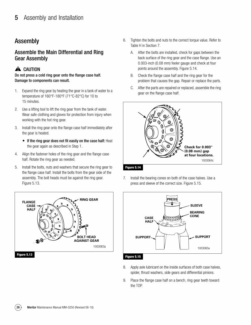
5. Install the bolts, nuts and washers that secure the ring gear to the flange case half. Install the bolts from the gear side of the assembly. The bolt heads must be against the ring gear. Figure 5.13.
Figure 5.13
6. Tighten the bolts and nuts to the correct torque value. Refer to Table H in Section 7.
A. After the bolts are installed, check for gaps between the back surface of the ring gear and the case flange. Use an 0.003-inch (0.08 mm) feeler gauge and check at four points around the assembly. Figure 5.14.
B. Check the flange case half and the ring gear for the problem that causes the gap. Repair or replace the parts.
C. After the parts are repaired or replaced, assemble the ring gear on the flange case half.
Figure 5.14
7. Install the bearing cones on both of the case halves. Use a press and sleeve of the correct size. Figure 5.15.
Figure 5.15
8. Apply axle lubricant on the inside surfaces of both case halves, spider, thrust washers, side gears and differential pinions.
9. Place the flange case half on a bench, ring gear teeth toward the TOP.
Figure 5.13
FLANGECASEHALF
RING GEAR
BOLT HEADAGAINST GEAR
1003063a
Figure 5.14
Figure 5.15
Check for 0.003"(0.08 mm) gapat four locations.
1003064c
CASEHALF
SUPPORTSUPPORT
PRESS
SLEEVE
BEARINGCONE
1003065a

5 Assembly and Installation
27Meritor Maintenance Manual MM-0250 (Revised 08-10)
10. Install one thrust washer and side gear into the flange case half. Figure 5.16.
Figure 5.16
11. Install the spider, differential pinions and thrust washers into the flange case half. Figure 5.17.
Figure 5.17
12. Install the second side gear and thrust washer over the spider and differential pinions. Figure 5.18.
Figure 5.18
13. Place the plain half of the differential case over the flange half and gears. Rotate the plain half as needed to align the match marks. Figure 5.18 and Figure 5.19.
Figure 5.19
14. Install Dri-Loc fasteners into the case halves. Refer toSection 4 and the following procedure.
A. Install four fasteners into the case halves, if required. The distance between the fasteners must be equal.
B. Tighten the fasteners to the correct torque value in a crisscross pattern. Refer to Figure 5.20 and Table H in Section 7.
C. Install the other fasteners into the case halves. Tighten the fasteners to the correct torque value. Refer to Table H in Section 7.
Figure 5.20
Figure 5.16
Figure 5.17
Figure 5.18
SIDEGEAR
THRUSTWASHER
FLANGECASE HALF
1003066a
SPIDER, PINIONAND THRUST WASHERS
1003067a
THRUSTWASHER
SIDE GEARPLAINCASE HALF
1003068a
Figure 5.19
Figure 5.20
PLAIN CASEHALF
MATCHMARKS
1003069a
2
12
7
395
111
8
410 6
13
14
15
16
1003070a
5 Assembly and Installation
28 Meritor Maintenance Manual MM-0250 (Revised 08-10)
15. Check the rotating resistance of the differential gears. Use the following procedure.
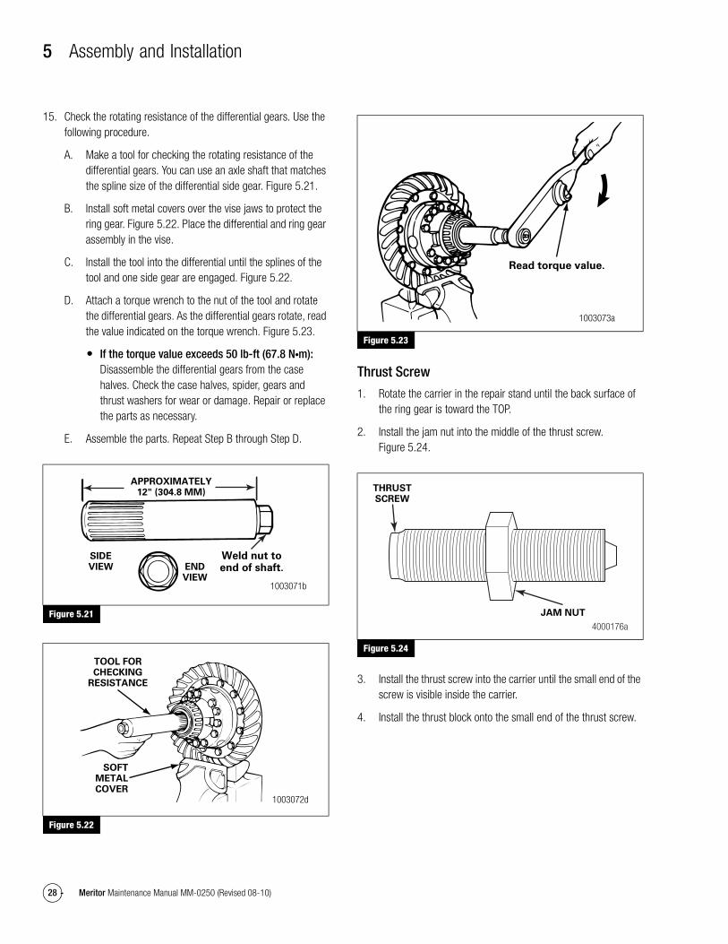
A. Make a tool for checking the rotating resistance of the differential gears. You can use an axle shaft that matches the spline size of the differential side gear. Figure 5.21.
B. Install soft metal covers over the vise jaws to protect the ring gear. Figure 5.22. Place the differential and ring gear assembly in the vise.
C. Install the tool into the differential until the splines of the tool and one side gear are engaged. Figure 5.22.
D. Attach a torque wrench to the nut of the tool and rotate the differential gears. As the differential gears rotate, read the value indicated on the torque wrench. Figure 5.23.
� If the torque value exceeds 50 lb-ft (67.8 N�m): Disassemble the differential gears from the case halves. Check the case halves, spider, gears and thrust washers for wear or damage. Repair or replace the parts as necessary.
E. Assemble the parts. Repeat Step B through Step D.
Figure 5.21
Figure 5.22
Figure 5.23
Thrust Screw
1. Rotate the carrier in the repair stand until the back surface of the ring gear is toward the TOP.
2. Install the jam nut into the middle of the thrust screw. Figure 5.24.
Figure 5.24
3. Install the thrust screw into the carrier until the small end of the screw is visible inside the carrier.
4. Install the thrust block onto the small end of the thrust screw.
Figure 5.21
Figure 5.22
APPROXIMATELY12" (304.8 MM)
SIDEVIEW
Weld nut toend of shaft.END
VIEW1003071b
TOOL FORCHECKING
RESISTANCE
SOFTMETALCOVER
1003072d
Figure 5.23
Figure 5.24
Read torque value.
1003073a
JAM NUT
4000176a
THRUSTSCREW

5 Assembly and Installation
29Meritor Maintenance Manual MM-0250 (Revised 08-10)
Differential and Ring Gear Assembly
1. Clean and dry the bearing cups and bores of the carrier legs and bearing caps.
2. Apply axle lubricant on the inner diameter of the bearing cups and on both bearing cones that are assembled on the case halves.
3. Apply Meritor specification 2297-P-3994, Loctite 680 adhesive, or equivalent into the bearing bores of the carrier legs and bearing caps. To obtain this adhesive, refer to the Service Notes page on the front inside cover of this manual. Don’t allow adhesive to contact adjusting ring threads. Refer to Section 4. Figure 5.25.
Figure 5.25
4. Install the bearing cups over the bearing cones that are assembled on the case halves. Figure 5.26.
Figure 5.26
5. Use lifting straps to lift the differential and ring gear assembly and install into the carrier. The bearing cups must be flat against the bores between the carrier legs. Figure 5.26.
6. Install both of the bearing adjusting rings into position between the carrier legs. Hand-tighten each adjusting ring against the bearing cup. Figure 5.27.
Figure 5.27
7. Install the bearing caps over the bearings and adjusting rings in the correct location as marked before removal. Figure 5.28.
Figure 5.28
Figure 5.25
Figure 5.26
ADHESIVE BEARINGCAP
CARRIERLEG
1003074a
BEARINGCUP
BEARINGCUP
LEGBORE
1003075a
Figure 5.27
Figure 5.28
ADJUSTINGRING
LEG
1003076a
BEARINGCAP
MATCHMARKS
1003077a

5 Assembly and Installation
30 Meritor Maintenance Manual MM-0250 (Revised 08-10)
WARNINGUse a brass or synthetic mallet for assembly and disassembly procedures. Do not hit steel parts with a steel hammer. Pieces of a part can break off. Serious personal injury and damage to components can result.
8. Seat each bearing cap with a leather, plastic or rubber mallet. The caps must fit easily against the bearings, adjusting rings and carrier. Do not force the bearing caps into position.
� If the bearing caps do not correctly fit into position: Check the match mark alignment between the caps and the carrier. Remove the caps. Repeat Step 6 through Step 8.
9. Install the capscrews and washers that secure the bearing caps to the carrier. Tighten the capscrews by hand four to six turns. Tighten the capscrews to the correct torque value. Refer to Table H in Section 7.
10. Do not install the cotter pins that secure the bearing adjusting rings. Adjust the preload of the differential bearings, the backlash of the gear, and check the tooth contact patterns.
Adjustment
Differential Bearing Preload
Use Method 1 or Method 2 below to adjust differential bearing preload.
Specifications
Method 1
1. Attach a dial indicator to the carrier mounting flange so that the pointer is against the ring gear’s back surface. Figure 5.29.
2. Use a T-bar wrench to loosen the bearing adjusting ring that’s opposite the ring gear. Figure 5.30. The dial indicator will show a small amount of end play.
Figure 5.29
Figure 5.30
3. Use one of the following procedures to move the differential and ring gear to the LEFT and RIGHT while you read the dial indicator.
A. Insert two pry bars between the bearing adjusting rings and the ends of the differential case. Figure 5.31. The pry bars must not touch the differential bearings.
B. Insert two pry bars between the differential case, or the ring gear and the carrier at locations other than specified in Step A. Figure 5.32. The pry bars must not touch the differential bearings.
Differential bearing preload all carrier models
15-35 lb-ft (1.7-3.9 N�m)
Expansion between bearing caps
0.002- to 0.009-inch (0.05-0.229 mm)
Figure 5.29
Figure 5.30
DIALINDICATOR
1003078c
"T" BARWRENCH
1003079b
ADJUSTINGRINGOPPOSITERING GEAR

5 Assembly and Installation
31Meritor Maintenance Manual MM-0250 (Revised 08-10)
Figure 5.31
Figure 5.32
4. Tighten the bearing adjusting ring until the dial indicator reads ZERO end play. Move the differential ring to the LEFT and RIGHT as needed. If necessary, repeat Step A or Step B.
5. Tighten each bearing adjusting ring one notch from ZERO.
6. Proceed to Check Ring Gear Runout, Radial Movement in this section.
Method 2
1. Hand-tighten both adjusting rings against the differential bearings.
2. Use a micrometer to measure the opposite surfaces of the bearing caps at X or Y. Figure 5.33 and Figure 5.34. Record the measurement.
Figure 5.33
Figure 5.34
3. Tighten each bearing adjusting ring one notch.
4. Measure the opposite surfaces of the bearing caps at X or Y again. Compare the measurement with the one you obtained in Step 2.
5. Subtract the measurement you obtained in Step 2 from the measurement in Step 4. The difference is the amount the bearing caps have expanded. Refer to the following example.
� If the measurement is 0.002-0.009-inch (0.05-0.229 mm): Proceed to Check Ring Gear Runout, Radial Movement in this section.
� If the measurement is not within the specification above: Repeat Step 3 and Step 4 as necessary.
Figure 5.31
Figure 5.32
1003080d
Pry bars mustnot touchbearings.
Pry bars mustnot touch bearings.
1003081c
Figure 5.33
Figure 5.34
1003082a
1003083a
MICROMETER

5 Assembly and Installation
32 Meritor Maintenance Manual MM-0250 (Revised 08-10)
Sample Differential Bearing Preload Calculation
Check Ring Gear Runout, Radial Movement
1. Attach a dial indicator onto the carrier’s mounting flange. Figure 5.35.
Figure 5.35
2. Adjust the dial indicator so that the pointer is against the back surface of the ring gear. Set the dial indicator to ZERO.
3. Rotate the differential and ring gear. Read the dial indicator. Runout must not exceed 0.008-inch (0.20 mm). Figure 5.35.
� If runout exceeds the specification above: Remove the differential and ring gear assembly from the carrier. Refer to Section 3, and Step 4 and Step 5 below.
4. Check the differential parts including the carrier for wear or damage. Repair or replace parts as necessary.
5. Install the differential and ring gear into the carrier. Refer to Differential and Ring Gear Assembly in this section.
6. Repeat the preload adjustment of the differential bearings.
Ring Gear Tooth Contact Pattern, BacklashUse the following procedure to adjust backlash.
1. Attach a dial indicator onto the carrier mounting flange. Figure 5.36.
2. Adjust the dial indicator so that the pointer is against the tooth surface. Figure 5.36.
Figure 5.36
3. Adjust the indicator dial to ZERO. Hold the drive pinion in position.
NOTE: When you adjust the backlash, only move the ring gear. Do not move the drive pinion.
4. After reading the dial indicator, rotate the differential and ring gear a small amount in both directions against the drive pinion teeth. Do not move the drive pinion.
� If the backlash reading is within specification: Check the tooth contact patterns.
� If the backlash reading is not within specifications: Adjust backlash as needed.
5. Loosen one bearing adjusting ring one notch, then tighten the opposite ring the same amount. Figure 5.37 and Figure 5.38.
A. To increase backlash: Move the ring gear away from the drive pinion. Figure 5.37.
B. To decrease backlash: Move the ring gear toward the drive pinion. Figure 5.38.
X or Y Measurement Before Tightening Adjusting Rings
X or Y Measurement After Tightening Adjusting Rings
Amount Bearing Caps Have Expanded
13.927-inch (353.74 mm)
13.936-inch (353.97 mm)
0.009-inch (0.23 mm)
Figure 5.35
Rotate ring gear.
DIALINDICATOR
1003084a
Figure 5.36
1001085a

5 Assembly and Installation
33Meritor Maintenance Manual MM-0250 (Revised 08-10)
Figure 5.37
Figure 5.38
6. Repeat Step 2 through Step 5 until the backlash is within specifications.
Specifications
Check Gear Set Tooth Contact Patterns, Backlash
Table D: Ring Gear Backlash Specifications
Old Gear Set
Adjust ring gear tooth contact patterns, backlash to the setting that was measured before the carrier was disassembled. Refer to the previous table for the correct specification
New Gear Set
Adjust ring gear tooth contact patterns, backlash to the correct specification from the previous table.
In the following procedures, movement of the contact pattern in the length of the tooth is indicated as toward the “heel” or “toe” of the ring gear. Figure 5.39.
Figure 5.39
Always check tooth contact patterns on the drive side of the gear teeth. The drive side is the concave side of the ring gear, unlike a conventional hypoid gear. Figure 5.41.
Gear Set Tooth Contact Patterns
1. Adjust the backlash of a new gear set to 0.012-inch (0.305 mm). Adjust the backlash of an old gear set to the setting that was measured before the carrier was disassembled. Refer to Ring Gear Tooth Contact Pattern, Backlash in this section.
2. Apply a marking compound to approximately 12 gear teeth of the ring gear. Rotate the ring gear so that the 12 gear teeth are next to the drive pinion. Figure 5.40.
Figure 5.40
Figure 5.37
Figure 5.38
Old gear set 0.008-0.018-inch (0.20-0.46 mm)
New gear set 0.012-inch (0.30 mm)
Tighten adjustingring this side.
Increase backlash.Loosen adjusting
ring this side.
1003087d
Loosen adjustingring this side.
Decrease backlash.
Tighten adjustingring this side.
1003088e
Figure 5.39
Figure 5.40
HEEL 1003090g
TOE
1001091a

5 Assembly and Installation
34 Meritor Maintenance Manual MM-0250 (Revised 08-10)
3. Rotate the ring gear FORWARD and BACKWARD so that the12 gear teeth go past the drive pinion six times to get the contact patterns. Repeat if needed to get a more clear pattern.
4. Look at the contact patterns on the ring gear teeth. Compare the patterns to Figure 5.41, Figure 5.42 and Figure 5.43.
The location of good hand-rolled contact patterns for new gear sets is from the central toe, center, to the central heel area of the gear tooth and in the center between the top and bottom of the tooth. Figure 5.41.
When the carrier is operated, a good hand-rolled pattern will extend approximately the full length of the gear tooth. The top of the pattern will be near the top of the gear tooth. Figure 5.44.
The location of a good hand-rolled contact pattern for an old gear set must match the wear pattern in the ring gear. The new contact pattern will be smaller in area than the old wear pattern.
A high-contact pattern indicates that the drive pinion was not installed deep enough into the carrier. A low-contact pattern indicates that the drive pinion was installed too deep in the carrier.
� If the contact patterns require adjustment: Continue by following Step 5 to move the contact patterns between the top and bottom of the gear teeth.
� If the contact patterns are in the center of the gear teeth: Proceed to Step 6.
Figure 5.41
Figure 5.42
Figure 5.43
Figure 5.44
Figure 5.41
4005527aGOOD HAND-ROLLED PATTERN
Figure 5.42
Figure 5.43
Figure 5.44
4005528aHIGH PATTERN
4005529aLOW PATTERN
1001095d
SATISFACTORY PATTERN IN OPERATION

5 Assembly and Installation
35Meritor Maintenance Manual MM-0250 (Revised 08-10)
5. Change the thickness of the shim pack under the bearing cage to move the contact patterns between the top and bottom of the gear teeth. Use the following procedure.
A. Remove the drive pinion and bearing cage from the carrier. Refer to Drive Pinion from the Carrier in Section 3.
B. To correct a high-contact pattern, increase the thickness of the shim pack under the bearing cage, which moves the drive pinion TOWARD the ring gear. Figure 5.42 and Figure 5.45.
To correct a low-contact pattern, decrease the thickness of shim pack under the bearing cage, which moves the drive pinion AWAY from the ring gear. Figure 5.46.
C. Install the drive pinion, bearing cage and shims into the carrier. The pinion cone number can be either 100ths of a millimeter or 1,000ths of an inch.
D. Repeat Step 2 through Step 5 until the contact patterns are in the center between the top and bottom of the gear teeth.
Figure 5.45
Figure 5.46
6. Adjust ring gear backlash within the correct specification to move the contact patterns to the correct location in the length of the gear teeth. Refer to Ring Gear Tooth Contact Pattern, Backlash in this section.
A. Increase backlash to move the contact patterns toward the toe of the ring gear teeth. Figure 5.47.
B. Decrease backlash to move the contact patterns toward the heel of the ring gear teeth. Figure 5.48.
C. Repeat Step 2 through Step 4 and Step 6 until the contact patterns are at the correct location in the length of the gear teeth.
Figure 5.47
Figure 5.48
Figure 5.45
Figure 5.46
1003102fIncrease shim pack.
1003101fDecrease shim pack.
Figure 5.47
Figure 5.48
Move pattern toward toe,tighten adjusting ring
this side.
Increase backlash.
Loosen adjusting ring.
1003103e
Move pattern toward heel,loosen adjusting
ring this side.
Decrease backlash.
Tighten adjusting ring.
1003104e

5 Assembly and Installation
36 Meritor Maintenance Manual MM-0250 (Revised 08-10)
7. Install the cotter pins between the lugs of the adjusting ring and through the boss of the bearing cap. Bend the two ends of the cotter key around the boss. Figure 5.49.
Figure 5.49
Thrust Screw
1. Install the thrust screw until the thrust block contacts the ring gear. Figure 5.50. Clearance between the thrust screw and the ring gear should be 0.025-0.045-inch (0.635-1.143 mm).
2. Loosen the thrust screw 1/2 turn or 180 degrees. Figure 5.51.
3. Tighten the jam nut to 100-200 lb-ft (136-272 N�m). @
Figure 5.50
Figure 5.51
Figure 5.49
Figure 5.50
COTTER PIN
1003105b
THRUSTSCREW AND
JAM NUT
1002993d
THRUSTBLOCK
Figure 5.51
4000166bLoosen thrust screw 1/2 turn.

5 Assembly and Installation
37Meritor Maintenance Manual MM-0250 (Revised 08-10)
Installation
Install the Differential Carrier into the Axle Housing
WARNINGSolvent cleaners can be flammable, poisonous and cause burns. Examples of solvent cleaners are carbon tetrachloride, and emulsion-type and petroleum-base cleaners. Read the manufacturer’s instructions before using a solvent cleaner, then carefully follow the instructions. Also follow the procedures below.
� Wear safe eye protection.
� Wear clothing that protects your skin.
� Work in a well-ventilated area.
� Do not use gasoline, or solvents that contain gasoline. Gasoline can explode.
� You must use hot solution tanks or alkaline solutions correctly. Read the manufacturer’s instructions before using hot solution tanks and alkaline solutions. Then carefully follow the instructions.
When you apply some silicone gasket materials, a small amount of acid vapor is present. To prevent serious personal injury, ensure that the work area is well-ventilated. Read the manufacturer’s instructions before using a silicone gasket material, then carefully follow the instructions. If a silicone gasket material gets into your eyes, follow the manufacturer’s emergency procedures. Have your eyes checked by a physician as soon as possible.
1. Clean the inside of axle housing and the carrier mounting surfaces. Use a cleaning solvent and rags to remove dirt. Blow dry the cleaned areas with air. Refer to Section 4.
2. Inspect the axle housing for damage. Repair or replace the axle housing. Refer to Section 4.
3. Check for loose studs in the mounting surface of the housing where the carrier fastens. Remove and clean the studs that are loose.
4. Apply Loctite 242 threadlocker, or equivalent, to the threaded holes and install the studs, if equipped, into axle housing. Refer to Section 4. To obtain this threadlocker, refer to the Service Notes page on the front inside cover of this manual. Tighten the studs to the correct torque value. Refer to Table H in Section 7.
5. Apply silicone gasket material to the mounting surface of the housing where the carrier fastens. Refer to Section 4. Figure 5.52.
Figure 5.52
6. Install the carrier into the axle housing. Use a hydraulic roller jack or a lifting tool.
CAUTIONDo not install the carriers using a hammer or mallet. A hammer or mallet will damage the mounting flange of the carrier and cause oil leaks.
7. Install the nuts and washers or capscrews and washers into the four corner locations around the carrier and axle housing. Hand-tighten the fasteners. Figure 5.53.
8. Carefully push the carrier into position. Tighten the four fasteners two or three turns each in a crisscross pattern. Figure 5.53.
Figure 5.52
1/8" (3.2 MM) DIA.SILICONE GASKET BEAD
1003110a

5 Assembly and Installation
38 Meritor Maintenance Manual MM-0250 (Revised 08-10)
Figure 5.53
9. Repeat Step 8 until the four fasteners are tightened to 150-230 lb-ft (203-312 N�m). @
10. Install the other fasteners and washers that hold the carrier in the axle housing. Tighten the fasteners to 150-230 lb-ft (203-312 N�m). @
11. Connect the driveline universal joint to the pinion input yoke or flange on the carrier.
12. Install the gaskets and axle shafts into the axle housing and carrier. The gasket and flange of the axle shafts must fit flat against the wheel hub. Figure 5.54.
Figure 5.54
Install the Axle Shafts
Straight Holes with Nuts and Hardened Washers
1. Clean the mating surfaces of the axle shaft and the wheel hub.
2. Apply a 1/8-inch (3 mm) diameter bead of silicone gasket material around the mating surface of the hub and around the edge of each fastener hole.
3. Install the gasket and the axle shaft into the housing. The gasket and the flange of the axle shaft must fit flat against the wheel hub. Figure 5.54.
NOTE: You can also install lock washers as an alternative.
4. Install the Grade 8 nuts and hardened washers on the stud. Tighten the stud nuts to the torque specified in Table H in Section 7.
Tapered Dowel with Hardened Washer and Hardened Nut
1. Clean the mating surfaces of the axle shaft and the wheel hub.
2. Apply a 1/8-inch (3 mm) diameter bead of silicone gasket material around the mating surface of the hub and around the edge of each fastener hole.
3. Install the gasket and the axle shaft into the housing. The gasket and the flange of the axle shaft must fit flat against the wheel hub. Figure 5.54.
4. Install solid tapered dowels over each stud and into the flange of the axle shaft. Use a punch or a drift and hammer, if necessary.
NOTE: You can also install lockwashers as an alternative.
5. Install the Grade 8 nuts and hardened washers on the stud. Tighten the stud nuts to the torque specified in Table H in Section 7.
Figure 5.53
Figure 5.54
1001105a
1003112a
TAPEREDDOWEL
GASKET
STUD
SHAFTHUBAXLE
AXLESHAFT ORFLANGE
WASHER
CAPSCREW
NON-TAPEREDDOWEL RETENTION
TAPERED DOWEL RETENTION
STUDNUT
WASHER

6 Lubrication
39Meritor Maintenance Manual MM-0250 (Revised 08-10)
6 LubricationNOTE: For complete information on lubricating drive axles and carriers, refer to Maintenance Manual 1, Preventive Maintenance and Lubrication. To obtain this publication, refer to the Service Notes page on the front inside cover of this manual.
Refer to Table E, Table F and Table G for information on lubricants, schedules and capacities. To obtain lubricants, refer to the Service Notes page on the front inside cover of this manual.
Table E: Lubricant Cross Reference, Viscosity and Temperature Chart
Table F: Oil Change Intervals and Specifications for All Rear Drive Axles
Meritor Lubricant Specification Description Cross Reference
Minimum Outside Temperature
Maximum Outside Temperature
O-76-A Hypoid Gear Oil GL-5, S.A.E. 85W/140 +10°F (–12.2°C) - - -**
O-76-B Hypoid Gear Oil GL-5, S.A.E. 80W/140 –15°F (–26.1°C) - - -**
O-76-D Hypoid Gear Oil GL-5, S.A.E. 80W/90 –15°F (–26.1°C) - - -**
O-76-E Hypoid Gear Oil GL-5, S.A.E. 75W/90 –40°F (–40°C) - - -**
O-76-J Hypoid Gear Oil GL-5, S.A.E. 75W –40°F (–40°C) +35°F (+1.6°C)
O-76-L Hypoid Gear Oil GL-5, S.A.E. 75W/140 –40°F (–40°C) - - -**
** There is no upper limit on these outside temperatures, but the axle sump temperature must never exceed 250°F (+121°C).
Vocation or Vehicle Operation Linehaul
Motorhome
City Delivery
Check Oil Level Every 25,000 miles (40 000 km) or the fleet maintenance interval (whichever comes first)
Every 10,000 miles (16 000 km), once a month or the fleet maintenance interval (whichever comes first)
Petroleum based oil change on axle WITH or WITHOUT pump and filter system
Every 100,000 miles (160 000 km) or annually, whichever comes first
Every 50,000 miles (80 000 km) or annually, whichever comes first
Synthetic oil change on axle WITHOUT pump and filter system*
Every 250,000 miles (400 000 km) or annually, whichever comes first
Every 100,000 miles (160 000 km) or annually, whichever comes first
Synthetic oil change on axle WITH pump and filter system*
Every 500,000 miles (800 000 km) Every 250,000 miles (400 000 km)
Filter change on axle with pump and filter system
Every 100,000 miles (160 000 km) Every 100,000 miles (160 000 km)
* This interval applies to approved semi-synthetic and full-synthetic oils only. For a list of approved extended-drain axle oils, refer to TP-9539, Approved Rear Drive Axle Lubricants. To obtain this publication, refer to the Service Notes page on the front inside cover of this manual.

6 Lubrication
40 Meritor Maintenance Manual MM-0250 (Revised 08-10)
Lubricant Capacities
Use the following lubricant capacities as a guide only. The capacities are measured with the drive pinion in the horizontal position. When the angle of the drive pinion changes, the lubricant capacity of the axle will change.
Table G: Lubricant Capacities
Axle Model
Capacity
U.S. Pints Liters
Forward Axle of Tandem
MT-40-143MA-N 30.2 14.3
Rear Axle of Tandem
MT-40-143MA-N 25.8 12.2

7 Specifications
41Meritor Maintenance Manual MM-0250 (Revised 08-10)
7 SpecificationsFastenersThe torque values in Table H are for fasteners that have a light application of oil on the threads.
� If the fasteners are dry: Increase the torque values by 10%.
� If the fasteners have a heavy application of oil on the threads: Decrease the torque values by 10%.
If you do not know the size of the fastener that is being installed, measure the fastener. Use the following procedure.
American Standard Fasteners
1. Measure the diameter of the threads in inches, dimension X. Figure 7.1.
2. Count the amount of threads there are in 1-inch. Figure 7.1.
3. Compare the size of the fastener measured to the list of fasteners in Table H to find the correct torque value.
Example
American Standard size fastener is 0.50-13.
� 0.50 is the diameter of the fastener in inches or dimension X.
� 13 is the amount of threads in 1-inch.
Metric Fasteners
1. Measure the diameter of the threads in millimeters (mm), dimension X. Figure 7.2.
2. Measure the distance of 10 threads, point to point in millimeters (mm), dimension Y. Make a note of dimension Y. Figure 7.2.
3. Divide the dimension Y by 10. The result will be the distance between two threads or pitch.
4. Compare the size of the fastener measured to the list of fasteners in Table H to find the correct torque value.
Figure 7.1
Figure 7.2
Examples
Fastener Type How to Measure
0.50-13
Standard American size (Figure 7.1)
0.50 = the diameter of the fastener in inches, dimension X
13 = the number of threads in one inch
M8 x 1.25
Metric (Figure 7.1)
M8 = the diameter in millimeters, dimension X
1.25 = the distance between two threads, pitch
Figure 7.1
Figure 7.2
AMOUNTOF THREADS
IN 1"
1"
X
1003113aX DIMENSION = EXAMPLE 1/2"
X
Y
1003114b
PITCH
X DIMENSION = EXAMPLE M8 OR 8 MMY DIMENSION = DISTANCE OF 10 THREADS

7 Specifications
42 Meritor Maintenance Manual MM-0250 (Revised 08-10)
Figure 7.3
4000262c
6
1
2
3
4
5
9
8
7
11
10

7 Specifications
43Meritor Maintenance Manual MM-0250 (Revised 08-10)
Table H: Torque Chart
* Some Meritor carriers do not have these parts.
Fastener Thread Size Torque Value lb-ft (N�m)
1. *Capscrew, Axle Shaft .31-24
.50-13
18-24
85-115
(24-33)
(115-156)
2. *Nut, Axle Shaft Stud Plain Nut
.44-20
.50-20
.56-18
.62-18
.75-16
Lock Nut
.44-20
.50-20
.56-18
.62-18
.75-16
50-75
75-115
110-165
150-230
310-400
40-65
65-100
100-145
130-190
270-350
(68-102)
(102-156)
(149-224)
(203-312)
(420-542)
(54-88)
(88-136)
(136-197)
(176-258)
(366-475)
3. Breather .38-18 20 minimum (27 minimum)
4. *Plug, Oil Fill, Housing .75-14 35 minimum (47.5 minimum)
5. *Plug, Heat Indicator .50-14 25 minimum (34 minimum)
6. Plug, Oil Drain .50-14 25 minimum (34 minimum)
7. Capscrew, Differential Case
Grade 12.9 Standard Hex Head
M12 x 1.75 95-115 (130-155)
8. *Nut, Ring Gear Bolt
Flange Head
Standard Hex Head M16 x 1.5 160-210 (220-290)
9. Capscrew, Bearing Cap M20 x 2.5 320-400 (430-540)
10. Jam Nut, Thrust Screw M22 x 1.5 100-200 (136-272)
11. Input Yoke-to-Input Shaft Nut M39 x 1.5 920-1130 (1250-1535)
— Capscrew, Carrier-to-Housing .62-11 150-230 (203-312)

7 Specifications
44 Meritor Maintenance Manual MM-0250 (Revised 08-10)
Table I: Drive Pinion Bearings — Preload
Table J: Drive Pinion — Depth in Carrier
Table K: Amboid Gear Set — Tooth Contact Patterns (Hand Rolled)
Table L: Main Differential Bearings — Preload
Table M: Main Differential Gears — Rotating Resistance
Specification New bearings 20 to 50 lb-in (2.26-5.7 N�m)
Used bearings 20 to 40 lb-in (2.8-4.5 N�m)
Adjustment Preload is controlled by the thickness of the spacer between bearings.
To increase preload, install a thinner spacer.
To decrease preload, install a thicker spacer.
Specification Install the correct amount of shims between the bearing cage and carrier. To calculate, use old shim pack thickness and new and old pinion cone numbers.
Adjustment Change the thickness of the shim pack to get a good gear tooth contact pattern.
Specification Conventional gear set Toward the toe of the gear tooth and in the center between the top and bottom of the tooth
Generoid gear set Between the center and toe of the tooth and in the center between the top and bottom of the tooth
Adjustment Tooth contact patterns are controlled by the thickness of the shim pack between the pinion bearing cage and carrier and by ring gear backlash
To move the contact pattern lower, decrease the thickness of the shim pack under the pinion bearing cage
To move the contact pattern higher, increase the thickness of the shim pack under the pinion bearing cage
To move the contact pattern toward the toe of the tooth, decrease backlash of the ring gear
To move the contact pattern toward the heel of the tooth, increase backlash of the ring gear
Specification 15-35 lb-in (1.7-3.9 N�m)
Expansion between bearing caps 0.002-0.009-inch (0.050-0.229 mm)
Adjustment Preload is controlled by tightening both adjusting rings after ZERO end play is reached.
Specification 50 lb-ft (68 N�m), applied to one side gear

7 Specifications
45Meritor Maintenance Manual MM-0250 (Revised 08-10)
Table N: Ring Gear — Backlash
Table O: Ring Gear — Runout
Specification 0.008-0.018-inch (0.20-0.46 mm) for an old gear set
0.012-inch (0.30 mm) for a new gear set
Adjustment Backlash is controlled by the position of the ring gear. Change backlash within specifications to get a good tooth contact pattern.
To increase backlash, move the ring gear away from the drive pinion.
To decrease backlash, move the ring gear toward the drive pinion.
Specification 0.008-inch (0.20 mm) maximum
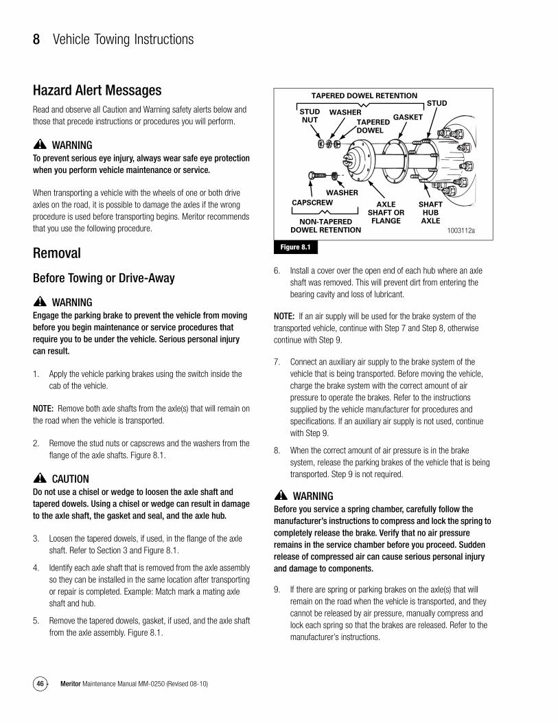
8 Vehicle Towing Instructions
46 Meritor Maintenance Manual MM-0250 (Revised 08-10)
8 Vehicle Towing InstructionsHazard Alert MessagesRead and observe all Caution and Warning safety alerts below and those that precede instructions or procedures you will perform.
WARNINGTo prevent serious eye injury, always wear safe eye protection when you perform vehicle maintenance or service.
When transporting a vehicle with the wheels of one or both drive axles on the road, it is possible to damage the axles if the wrong procedure is used before transporting begins. Meritor recommends that you use the following procedure.
Removal
Before Towing or Drive-Away
WARNINGEngage the parking brake to prevent the vehicle from moving before you begin maintenance or service procedures that require you to be under the vehicle. Serious personal injury can result.
1. Apply the vehicle parking brakes using the switch inside the cab of the vehicle.
NOTE: Remove both axle shafts from the axle(s) that will remain on the road when the vehicle is transported.
2. Remove the stud nuts or capscrews and the washers from the flange of the axle shafts. Figure 8.1.
CAUTIONDo not use a chisel or wedge to loosen the axle shaft and tapered dowels. Using a chisel or wedge can result in damage to the axle shaft, the gasket and seal, and the axle hub.
3. Loosen the tapered dowels, if used, in the flange of the axle shaft. Refer to Section 3 and Figure 8.1.
4. Identify each axle shaft that is removed from the axle assembly so they can be installed in the same location after transporting or repair is completed. Example: Match mark a mating axle shaft and hub.
5. Remove the tapered dowels, gasket, if used, and the axle shaft from the axle assembly. Figure 8.1.
Figure 8.1
6. Install a cover over the open end of each hub where an axle shaft was removed. This will prevent dirt from entering the bearing cavity and loss of lubricant.
NOTE: If an air supply will be used for the brake system of the transported vehicle, continue with Step 7 and Step 8, otherwise continue with Step 9.
7. Connect an auxiliary air supply to the brake system of the vehicle that is being transported. Before moving the vehicle, charge the brake system with the correct amount of air pressure to operate the brakes. Refer to the instructions supplied by the vehicle manufacturer for procedures and specifications. If an auxiliary air supply is not used, continue with Step 9.
8. When the correct amount of air pressure is in the brake system, release the parking brakes of the vehicle that is being transported. Step 9 is not required.
WARNINGBefore you service a spring chamber, carefully follow the manufacturer’s instructions to compress and lock the spring to completely release the brake. Verify that no air pressure remains in the service chamber before you proceed. Sudden release of compressed air can cause serious personal injury and damage to components.
9. If there are spring or parking brakes on the axle(s) that will remain on the road when the vehicle is transported, and they cannot be released by air pressure, manually compress and lock each spring so that the brakes are released. Refer to the manufacturer’s instructions.
Figure 8.1
1003112a
TAPEREDDOWEL
GASKET
STUD
SHAFTHUBAXLE
AXLESHAFT ORFLANGE
WASHER
CAPSCREW
NON-TAPEREDDOWEL RETENTION
TAPERED DOWEL RETENTION
STUDNUT
WASHER
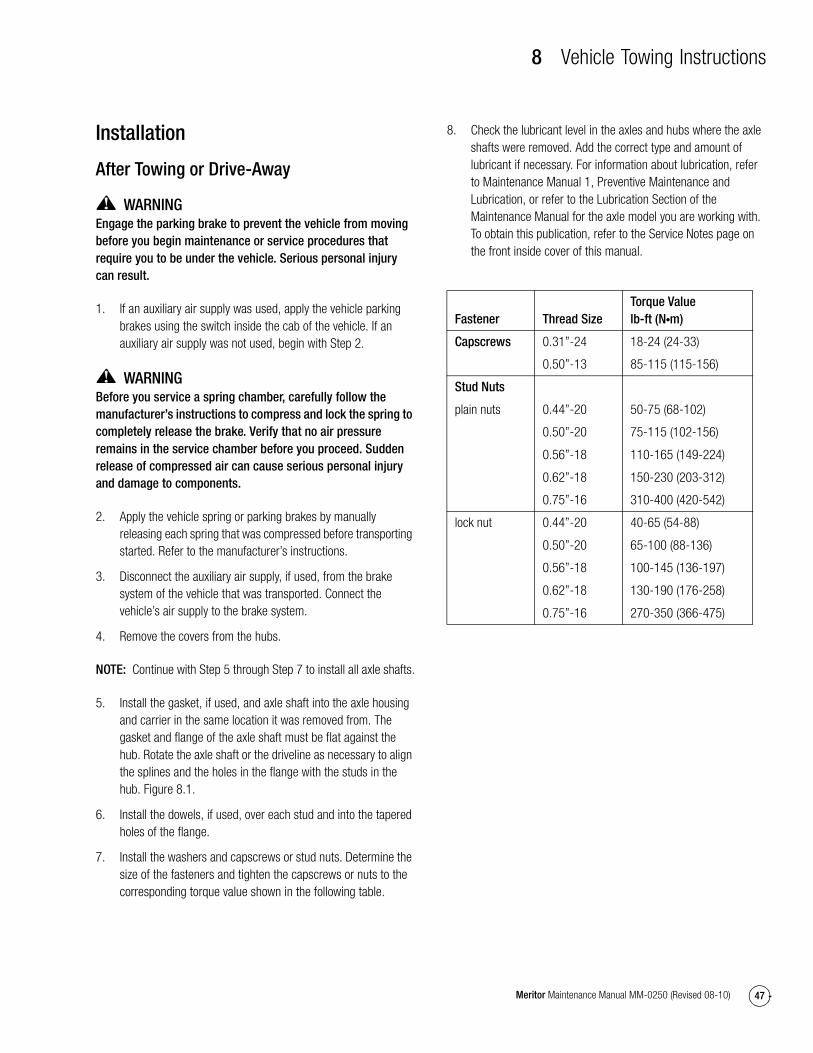
8 Vehicle Towing Instructions
47Meritor Maintenance Manual MM-0250 (Revised 08-10)
Installation
After Towing or Drive-Away
WARNINGEngage the parking brake to prevent the vehicle from moving before you begin maintenance or service procedures that require you to be under the vehicle. Serious personal injury can result.
1. If an auxiliary air supply was used, apply the vehicle parking brakes using the switch inside the cab of the vehicle. If an auxiliary air supply was not used, begin with Step 2.
WARNINGBefore you service a spring chamber, carefully follow the manufacturer’s instructions to compress and lock the spring to completely release the brake. Verify that no air pressure remains in the service chamber before you proceed. Sudden release of compressed air can cause serious personal injury and damage to components.
2. Apply the vehicle spring or parking brakes by manually releasing each spring that was compressed before transporting started. Refer to the manufacturer’s instructions.
3. Disconnect the auxiliary air supply, if used, from the brake system of the vehicle that was transported. Connect the vehicle’s air supply to the brake system.
4. Remove the covers from the hubs.
NOTE: Continue with Step 5 through Step 7 to install all axle shafts.
5. Install the gasket, if used, and axle shaft into the axle housing and carrier in the same location it was removed from. The gasket and flange of the axle shaft must be flat against the hub. Rotate the axle shaft or the driveline as necessary to align the splines and the holes in the flange with the studs in the hub. Figure 8.1.
6. Install the dowels, if used, over each stud and into the tapered holes of the flange.
7. Install the washers and capscrews or stud nuts. Determine the size of the fasteners and tighten the capscrews or nuts to the corresponding torque value shown in the following table.
8. Check the lubricant level in the axles and hubs where the axle shafts were removed. Add the correct type and amount of lubricant if necessary. For information about lubrication, refer to Maintenance Manual 1, Preventive Maintenance and Lubrication, or refer to the Lubrication Section of the Maintenance Manual for the axle model you are working with. To obtain this publication, refer to the Service Notes page on the front inside cover of this manual.
Fastener Thread SizeTorque Valuelb-ft (N�m)
Capscrews 0.31”-24
0.50”-13
18-24 (24-33)
85-115 (115-156)
Stud Nuts
plain nuts 0.44”-20
0.50”-20
0.56”-18
0.62”-18
0.75”-16
50-75 (68-102)
75-115 (102-156)
110-165 (149-224)
150-230 (203-312)
310-400 (420-542)
lock nut 0.44”-20
0.50”-20
0.56”-18
0.62”-18
0.75”-16
40-65 (54-88)
65-100 (88-136)
100-145 (136-197)
130-190 (176-258)
270-350 (366-475)
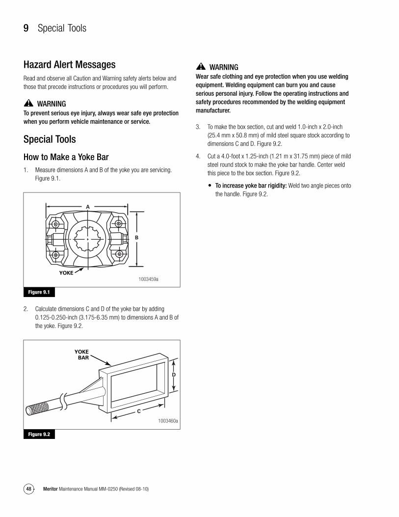
9 Special Tools
48 Meritor Maintenance Manual MM-0250 (Revised 08-10)
9 Special ToolsHazard Alert MessagesRead and observe all Caution and Warning safety alerts below and those that precede instructions or procedures you will perform.
WARNINGTo prevent serious eye injury, always wear safe eye protection when you perform vehicle maintenance or service.
Special Tools
How to Make a Yoke Bar1. Measure dimensions A and B of the yoke you are servicing.
Figure 9.1.
Figure 9.1
2. Calculate dimensions C and D of the yoke bar by adding 0.125-0.250-inch (3.175-6.35 mm) to dimensions A and B of the yoke. Figure 9.2.
Figure 9.2
WARNINGWear safe clothing and eye protection when you use welding equipment. Welding equipment can burn you and cause serious personal injury. Follow the operating instructions and safety procedures recommended by the welding equipment manufacturer.
3. To make the box section, cut and weld 1.0-inch x 2.0-inch (25.4 mm x 50.8 mm) of mild steel square stock according to dimensions C and D. Figure 9.2.
4. Cut a 4.0-foot x 1.25-inch (1.21 m x 31.75 mm) piece of mild steel round stock to make the yoke bar handle. Center weld this piece to the box section. Figure 9.2.
� To increase yoke bar rigidity: Weld two angle pieces onto the handle. Figure 9.2.Figure 9.1
Figure 9.2
A
B
YOKE
1003459a
C
D
YOKEBAR
1003460a

9 Special Tools
49Meritor Maintenance Manual MM-0250 (Revised 08-10)
Carrier Repair Stand Specifications
Refer to the Service Notes page on the front inside cover of this manual to obtain this repair stand.
Figure 9.3
1002990a
HANDLE 7" LONG
WITH SLOT IN
ONE END TO FIT
CLAMP SCREW
PLATES 8" LONG x 3/4"
THICK x 1-1/4" WIDE WITH
A TONGUE TO FIT SLOT IN
BAR WELD PLATES TO BAR
WELD ALL AROUND
AFTER PRESSING
PLUG IN PIPE
BAR 2" DIAMETER x 9"
LONG WITH ONE END
SLOTTED TO FIT PLATE
SHAPE AND SIZE
OF HOLES TO FIT
CARRIER
WELD
CHAMFER END
OF PIPE FOR
WELDING
23-1/2" CENTER
TO CENTER OF PIPE
PLUG 4" DIAMETER x 7" LONG
WITH ONE END TURNED 3" LONG
TO FIT PIPE. DRILL 2" HOLE AND
MILL 3/16" WIDE SLOT 2" FROM TOP
4" DIAMETER
PIPE
DRILL 3/8" HOLE
THROUGH HANDLE
AND SCREW
SCREW 3-1/2" LONG
x 5/8" DIAMETER WITH
FLATS ON END TO FIT
HANDLE AND 2-1/2" LENGTH
OF THREAD ON OTHER END

9 Special Tools
50 Meritor Maintenance Manual MM-0250 (Revised 08-10)
Specifications
Multiple Lip Seals (MLS) and Seal DriversRefer to Table P for information on multiple lip seals and seal drivers. To obtain Meritor seal driver KIT 4454, refer to the Service Notes page on the front inside cover of this manual.
Table P: Multiple Lip Seals and Seal Drivers*
Forward input and output seals must be serviced with the seal and sleeve. The service part number provides both when required.
Single Models Tandem Models Axle Model and PositionSeal Service Part Number
Previous Seal Part Number
Seal Drivers Sleeve Drivers
MX-21-160
MX-23-160R
RF-16-145
RF-21-160
RF-22-166
RF-23-185
RS-17-145
RS-19-145
RS-21-145
RS-21-160
RS-23-160 /A
RS-23-161 /A
RS-25-160 /A
RS-23-186
RS-26-185
RS-30-185
RT-34-144 /P
RT-34-145 /P
MT-40-143
RT-40-145 /A /P
RT-40-149 /A /P
RT-44-145 /P
RT-40-160 /A /P
RT-40-169 /A /P
RT-46-160 /A /P
RT-46-169 /A /P
RT-46-164EH /P
RT-46-16HEH /P
RT-50-160 /P
RT-52-185*
RT-58-185*
14X/16X/18X/38X Forward-Rear Unit Input (FUI)
A1-1205X2728 A-1205R2592 2728T1 2728T2
14X/16X Forward-Rear Unit Output (FUO)
A1-1205Y2729 A-1205P2590 2729T1 2729T2
14X Rear-Rear Unit Input (RUI)
A1-1205Z2730 A-1205N2588 2730T1 Not Required — Sleeve is unitized
16X/18X Rear-Rear Unit Input (RUI)
A1-1205A2731 A-1205Q2591 2731T1 Not Required — Sleeve is unitized
* Forward and rear input only.

Meritor Heavy Vehicle Systems, LLC2135 West Maple Road Printed in USATroy, MI 48084 USA866-OnTrac1 (668-7221) Copyright 2010 Revised 08-10meritor.com Meritor, Inc. Maintenance Manual MM-0250 (16579)