maintenance instructions paco instant...
TRANSCRIPT

INSTALLATION, OPERATION ANDMAINTENANCE INSTRUCTIONS
IMPORTANT! Read all instructions in this manual before operating pump. As a result of constant product improvement program, product changes may occur. As such Grundfos CBS, Inc. reserves the right to change product without prior written notifi cation.
Form No. 108037-Rev. J
Series: PIP500B PIP501B PIP520B PIP521B PIP502B PIP522B PIP523B PIP503B PIP524B PIP525B
PACO INSTANT PUMPSSubmersible Non-Clog Pumps
D4d.1c
4/06
Supersedes 7/05
PUMPSPACO®

2
Please Read This Before Installing Or Operating Pump.
This information is provided for SAFETY and to PREVENT
EQUIPMENT PROBLEMS. To help recognize this information,
observe the following symbols:
IMPORTANT! Warns about hazards that can result
in personal injury orIndicates factors concerned with
assembly, installation, operation, or maintenance which
could result in damage to the machine or equipment if
ignored.
CAUTION! Warns about hazards that can or will cause minor
personal injury or property damage if ignored. Used with symbols
below.
WARNING! Warns about hazards that can or will cause serious
personal injury, death, or major property damage if ignored. Used
with symbols below.
Only qualifi ed personnel should install, operate and repair
pump. Any wiring of pumps should be performed by a qualifi ed
electrician.
WARNING ! To reduce risk of electrical shock, pumps
and control panels must be properly grounded in
accordance with the National Electric Code (NEC) or
the Canadian Electrical Code (CEC) and all applicable
state, province, local codes and ordinances. Improper
grounding voids warranty.
WARNING! To reduce risk of electrical shock, always
disconnect the pump from the power source before
handling or servicing. Lock out power and tag.
WARNING! Operation against a closed
discharge valve will cause premature bearing
and seal failure on any pump, and on end
suction and self priming pump the heat build
may cause the generation of steam with resulting dangerous
pressures. It is recommended that a high case temperature
switch or pressure relief valve be installed on the pump body.
CAUTION ! Never operate a pump with a plug-in type
power cord without a ground fault circuit interrupter.
CAUTION ! Pumps build up heat and pressure
during operation-allow time for pumps to cool
before handling or servicing.
WARNING ! Do not pump hazardous materials
(fl ammable, caustic, etc.) unless the pump is specifi cally
designed and designated to handle them.
CAUTION ! Do not block or restrict discharge hose, as
discharge hose may whip under pressure.
WARNING ! Do not wear loose clothing that may
become entangled in moving parts.
WARNING ! Keep clear of suction and discharge
openings. DO NOT insert fi ngers in pump with power
connected.
Always wear eye protection when working on pumps.
Make sure lifting handles are securely fastened each
time before lifting. DO NOT operate pump without safety
devices in place. Always replace safety devices that
have been removed during service or repair. Secure the
pump in its operating position so it can not tip over, fall
or slide.
DO NOT exceed manufacturers recommendation for
maximum performance, as this could cause the motor
to overheat.
DO NOT remove cord and strain relief. DO NOT connect
conduit to pump.
WARNING ! Cable should be protected at all times to
avoid punctures, cut, bruises and abrasions. Inspect
frequently. Never handle connected power cords with
wet hands.
WARNING ! To reduce risk of electrical shock, all wiring
and junction connections should be made per the NEC
or CEC and applicable state or province and local
codes. Requirements may vary depending on usage
and location.
WARNING! Submersible Pumps are not approved for
use in swimming pools, recreational water installations
decorative fountains or any installation where human
contact with the pumped fl uid is common.
WARNING! Products returned must be cleaned,
sanitized, or decontaminated as necessary prior to
shipment, to insure that employees will not be exposed
to health hazards in handling said material. All Applicable
Laws And Regulations Shall Apply.
Bronze/brass and bronze/brass fi tted pumps may
contain lead levels higher than considered safe for
potable water systems. Lead is known to cause cancer
and birth defects or other reproductive harm. Various
government agencies have determined that leaded
copper alloys should not be used in potable water
applications. For non-leaded copper alloy materials of
construction, please contact factory.
PACO® Pumps is not responsible for losses, injury, or
death resulting from a failure to observe these safety
precautions, misuse or abuse of pumps or equipment.
SAFETY FIRST!
Hazardous fl uids can cause fi re or explo-sions, burnes or death could result.
Extremely hot - Severe burnes can occur on contact.
Biohazard can cause serious personal injury.
Hazardous fl uids can Hazard-ous pressure, eruptions or ex-plosions could cause personal injury or property damage.
Rotating machineryAmputation or severe laceration can result.
Hazardous voltage can shock, burn or cause death.
Other brand and product names are trademarks or registered trademarks of their respective holders.
2000, 2001, 2002, 5/05, 7/05, 4/06 Alteration Rights Reserved

3
DISCHARGE ....................... 3” NPT, Female, Vertical
LIQUID TEMPERATURE .... 104°F (40°C) Continuous
VOLUTE .............................. Cast Iron ASTM A-48, Class 30
MOTOR HOUSING ............. Cast Iron ASTM A-48, Class 30
SEAL PLATE ...................... Cast Iron ASTM A-48, Class 30
IMPELLER:
Design ............ 2 vane, Open with pump out vanes
on back side. Balanced, ISO G6.3
Material ........... Cast Iron ASTM A-48, Class 30
SHAFT ................................. 416 Stainless Steel
O-RINGS ............................. Buna-N
HARDWARE ....................... 300 Series Stainless Steel
PAINT .................................. Air dry enamel
SEAL Design ............. Single Mechanical
Material ........... Rotating Face - Carbon
Stationary Face - Ceramic
Elastomer - Buna-N
Hardware - 300 series stainless steel
CORD ENTRY ..................... 15Ft. (4.5m) Cord. Plug on 120 Volt,
Quick Connect, Custom Molded for
sealing and strain relief
UPPER BEARING:
Design ............. Single Row, Ball, Oil Lubricated
Load ................ Radial
LOWER BEARING:
Design ............. Single Row, Ball, Oil Lubricated
Load ................ Radial & Thrust
MOTOR: Design ............. NEMA L - Single Phase, NEMA B
Three Phase Torque Curve. Oil Filled
Squirrel Cage Induction
Insulation ........ Class B
SINGLE PHASE .................. Permanent Split Capacitor (PSC)
Includes Overload Protection in Motor
THREE PHASE ................... Tri Voltage 200-240/480. Requires
Overload Protection to be Included in
Control Panel
PUMP SPECIFICATIONS:
inches
(mm)
FIGURE 1
PUMP MODEL NO.
PUMP SERIAL NO.
MODEL NO
HP VOLT/PH Hz RPM(Nom)
NEMASTARTCODE
FULLLOADAMPS
LOCKEDROTORAMPS
CORDSIZE
CORDTYPE
CORDSIZE
WINDING RESISTANCEEmersonMain-Start
FranklinMain-Start
G.E.Main-Start
PIP500B 0.5 120/1 60 1750 F 11.6 21.3 14/3 SJTOW 0.375 ----- ------ 1.51-16.1
PIP501B 0.5 240/1 60 1750 J 5.9 14.9 14/3 SOW 0.530 3.38-9.30 ----- 5.69-18.74
PIP520B 0.5 200-240/3 60 1750 H/L 3.2/3.0 9.8/11.0 14/4 SOW 0.570 10.2 13.0 -----
PIP521B 0.5 480/3 60 1750 K 1.5 5.3 14/4 SOW 0.570 40.8 52.0 -----
PIP502B 0.75 200-240/1 60 1750 G/K 7.4/7.0 21.5/25.8 14/3 SOW 0.530 1.86-10.2 ----- 2.74-10.56
PIP522B 0.75 200-240/3 60 1750 H/K 4.8/4.5 13.7/15.4 14/4 SOW 0.570 ----- 5.49 6.28
PIP523B 0.75 480/3 60 1750 K 2.2 7.7 14/4 SOW 0.570 ----- 21.96 24.51
PIP503B 1.0 200-240/1 60 1750 D/G 8.8/8.3 21.5/25.8 14/3 SOW 0.530 1.86-10.2 ----- 2.74-10.56
PIP524B 1.0 200-240/3 60 1750 E/H 5.14/4.9 13.7/15.4 14/4 SOW 0.570 ----- 5.49 6.28
Winding Resistance ± 5%. Pump rated for operation at ± 10% voltage at motor.
4
SECTION B: GENERAL INFORMATION
B-1) To The Purchaser:
Your new Submersible Pump is constructed of the best
available materials and is designed to give you many years
of service with a minimum of attention.
This manual will provide helpful information concerning
installation, maintenance, and proper service guidelines.
Check local codes and requirements before installation.
Servicing should be performed by knowledgeable pump
service contractors or authorized service stations. The pump
is packaged ready for installation and no connections or
adjustments are necessary except for attaching discharge
piping and connecting service cord.
B-2) Receiving:
Upon receiving the pump, it should be inspected for
damage or shortages. If damage has occurred, fi le a claim
immediately with the company that delivered the pump. If
the manual is removed from the crating, DO NOT lose or
misplace.
SECTION C: INSTALLATION
C-1) Location:
These pumping units are self-contained and are recommended
for use in a sump, lift station or basin. The sump, lift station or
basin shall be vented in accordance with local plumbing codes.
This pump is designed to pump sewage, effl uent, or other
nonexplosive or noncorrosive wastewater. and shall
NOT be installed in locations classifi ed as hazardous in
accordance with the National Electrical Code (NEC), ANSI/
NFPA 70 or the Canadian Electrical Code (CEC).
Never install the pump in a trench, ditch or hole with a dirt
bottom; the legs will sink into the dirt and the suction will
become plugged.
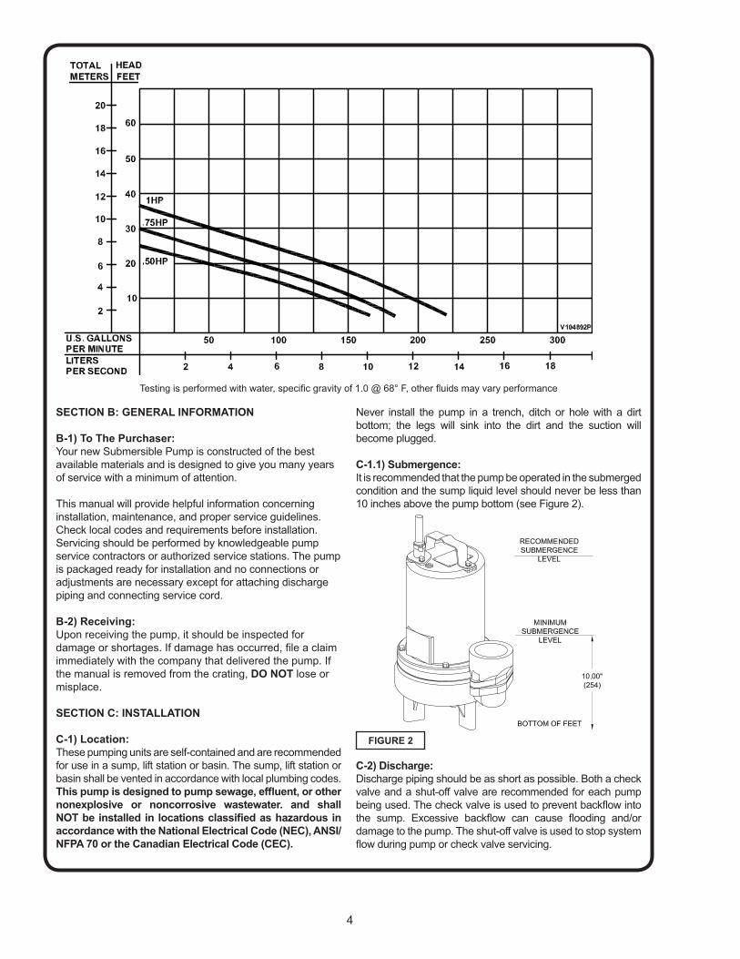
C-1.1) Submergence:
It is recommended that the pump be operated in the submerged
condition and the sump liquid level should never be less than
10 inches above the pump bottom (see Figure 2).
C-2) Discharge:
Discharge piping should be as short as possible. Both a check
valve and a shut-off valve are recommended for each pump
being used. The check valve is used to prevent backfl ow into
the sump. Excessive backfl ow can cause fl ooding and/or
damage to the pump. The shut-off valve is used to stop system
fl ow during pump or check valve servicing.
FIGURE 2
Testing is performed with water, specifi c gravity of 1.0 @ 68° F, other fl uids may vary performance

5
C-3) Liquid Level Controls (Not Included with Pump):
The level controls are to be supported by a mounting bracket
that is attached to the sump wall, cover or junction box. Be
certain that the level controls cannot hang up or foul in it’s
swing and that the pump is completely submerged when the
level control is in the “Off” mode.
Figure 3 shows a typical connection for 120 volt pumps
with piggy-back plug and a wide angle fl oat. For manual
and automatic operations.
Automatic - Plug fl oat cord into outlet, then plug
pump cord into fl oat cord.
Manual - Plug pump cord directly into outlet.
C-4) Electrical Connections:
An acceptable motor control switch shall be provided at
the time of installation.
C-4.1) Power Cable:
The cord assembly mounted to the pump must not be
modifi ed in any way except for shortening to a specifi c
application. Any splice between the pump and the control
panel must be made in accordance with all applicable
electric codes. It is recommended that a junction box, if
used, be mounted outside the sump or be of at least Nema
4 (EEMAC-4) construction if located within the wet well.
Do not use the power cable to lift pump. NOTE: The
white wire is NOT a neutral or ground lead, but a power
carrying conductor.
C-4.2) Overload Protection :
Single Phase - The type of in-winding overload protector
used is referred to as an inherent overheating protector
and operates on the combined effect of temperature and
current. This means that the overload protector will trip out
and shut the pump off if the windings become too hot, or
the load current passing through them becomes too high. It
will then automatically reset and start the pump up after the
motor cools to a safe temperature.
In the event of an overload, the source of this condition
should be determined and rectifi ed immediately. DO NOT
LET THE PUMP CYCLE OR RUN IF AN OVERLOAD
CONDITION OCCURS !
If current through the temperature sensor exceeds the
values listed, an intermediate control circuit relay must
be used to reduce the current or the sensor will not work
properly.
TEMPERATURE SENSOR ELECTRICAL RATINGS
Volts Continuous
Amperes
Inrush
Amperes
110-120 3.00 30.0
220-240 1.50 15.0
440-480 0.75 7.50
C-4.3) Wire Size:
Consult a qualifi ed electrician for proper wire size if
additional power cable length is required. See table on page
3 for electrical information.
SECTION: D START-UP OPERATION
D-1) Check Voltage and Phase:
Before operating pump, compare the voltage and phase
information stamped on the pump’s identifi cation plate to
the available power.
D-2) Check Pump Rotation:Before putting pump into service for the fi rst time, the motor rotation must be checked. Improper motor rotation can result in poor pump performance and can damage the motor and/or pump. To check the rotation, suspend the pump freely, momentarily apply power and observe the “kickback”. “Kickback” should always be in a counter-clockwise direction as viewed from the top of the pump motor housing.
D-2.1) Incorrect Rotation for Three-Phase Pumps:In the event that the rotation is incorrect for a three-phase installation, interchange any two power cable leads at the control box. DO NOT change leads in the cable housing in the motor. Recheck the “kickback” rotation again by momentarily applying power.
D-2.2) Incorrect Rotation for Single-Phase Pumps:In the unlikely event that the rotation is incorrect for a single phase pump, contact a PACO PUMPS Service Center.
D-3) Identifi cation Plate:Record the numbers from the pump’s identifi cation plate for future reference.
D-4) Insulation Test:Before the pump is put into service, an insulation (megger) test should be performed on the motor. The resistance values (ohms) as well as the voltage (volts) and current (amps) should be recorded.
D-5) Pump-Down Test:After the pump has been properly wired and lowered into the basin, sump or lift station, it is advisable to check the system by fi lling with liquid and allowing the pump to operate
through it’s pumping cycle. The time needed to empty the
system, or pump-down time along with the volume of water,
should be recorded.
FIGURE 3
Automatic
Manual

6
ECTION E: PREVENTATIVE MAINTENANCE
As the motor is oil fi lled, no lubrication or other maintenance
is required, and generally will give very reliable service and
can be expected to operate for years on normal sewage
pumping without failing. However as with any mechanical
piece of equipment a preventive maintenance program
is recommended and suggested to include the following
checks:
1) Inspect motor chamber for oil level and contamination
and repair as required per section F-1.
2) Inspect impeller and body for excessive build-up or
clogging and repair as required per section F-2.
3) Inspect motor and bearings and replace as required
per section F-3.
4) Inspect seal for wear or leakage and repair as
required per section F-4.
SECTION F: SERVICE AND REPAIR
NOTE: All item numbers in ( ) refer to Figure 15.
F-1) Lubrication:
Anytime the pump is removed from operation, the cooling
oil in the motor housing (5) should be checked visually for
oil level and contamination.
F-1.1) Checking Oil:
Motor Housing- To check oil, set unit upright. Remove pipe
plug (27) from housing (5). With a fl ashlight, visually inspect
the oil in the motor housing (5) to make sure it is clean
and clear, light amber in color and free from suspended
particles. Milky white oil indicates the presence of water.
Oil level should be just above the motor when pump is in
vertical position.
F-1.2) Testing Oil:
1.) Place pump on it’s side, remove pipe plug (27), from
motor housing (5) and drain oil into a clean, dry
container.
2.) Check oil for contamination using an oil tester with a
range to 30 Kilovolts breakdown.
3.) If oil is found to be clean and uncontaminated
(measuring above 15 KV. breakdown), refi ll the motor
housing as per section F-1.4.
4.) If oil is found to be dirty or contaminated (or measures
below 15 KV. breakdown), the the pump must be
carefully inspected for leaks at the shaft seal (24),
cable assembly (13), square ring (23) and pipe plug
(27), before refi lling with oil. To locate the leak, perform
a pressure test as per section F-1.3. After leak is
repaired, dispose of old oil properly, and refi ll with new
oil as per section F-1.4.
F-1.3) Pressure Test:
Pumps that have been disassembled, Motor Housing:
If the pump has been disassembled, the oil should be drained
before a pressure test, as described in section F-1.1. Remove
pipe plug (27) from motor housing (5). Apply pipe sealant to
pressure gauge assembly and tighten into hole
(See Figure 4).
Pressurize motor housing to 10 P.S.I. Use soap solution
around the sealed areas and inspect joints for “air
bubbles”. If, after fi ve minutes, the pressure is still holding
constant, and no “bubbles” are observed, slowly bleed the
pressure and remove the gauge assembly. Replace oil as
described in section F-1.4. If the pressure does not hold,
then the leak must be located and repaired.
CAUTION ! - Pressure builds up extremely fast, increase pressure by “TAPPING” air nozzle. Too much pressure will damage seal. DO NOT exceed 10 P.S.I.
Pumps that have NOT been disassembled, Motor Housing:
The pressure test may be done with the oil at its normal
level. Remove pipe plug (27) from motor housing (5). Apply
pipe sealant to pressure gauge assembly and tighten into
hole (see Figure 4). Pressurize motor housing to 10 P.S.I.
Use soap solution around the sealed areas above the oil
level and inspect joints for “air bubbles”. For sealed areas
below the oil level, leaks will seep oil.
If, after fi ve minutes, the pressure is still holding constant,
and no “bubbles”/oil seepage is observed, slowly bleed the
pressure and remove the gauge assembly. If the pressure
does not hold, then the leak must be located and repaired.
F-1.4) Replacing Oil:
Motor Housing - Set unit upright and refi ll with new cooling
oil as per Table 1 (see parts list for amount). Fill to just above
motor as an air space must remain in the top of the motor
housing to compensate for oil expansion. Apply pipe thread
compound to threads of pipe plug (27) then assemble to
motor housing (5).
IMPORTANT! - For single phase units, oil level should be below capacitor.
FIGURE 4
Remove
Plug
Pressure Gauge Assembly � 10 PSI
AIR
7
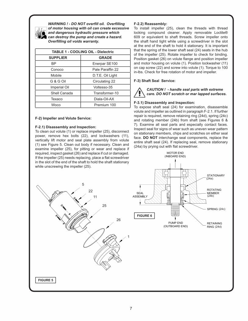
WARNING ! - DO NOT overfi ll oil. Overfi lling of motor housing with oil can create excessive and dangerous hydraulic pressure which can destroy the pump and create a hazard. Overfi lling oil voids warranty.
TABLE 1 - COOLING OIL - Dielectric
SUPPLIER GRADE
BP Enerpar SE100
Conoco Pale Paraffi n 22
Mobile D.T.E. Oil Light
G & G Oil Circulating 22
Imperial Oil Voltesso-35
Shell Canada Transformer-10
Texaco Diala-Oil-AX
Woco Premium 100
F-2) Impeller and Volute Service:
F-2.1) Disassembly and Inspection:
To clean out volute (1) or replace impeller (25), disconnect
power, remove hex bolts (22), and lockwashers (11),
vertically lift motor and seal plate assembly from volute
(1) see Figure 5. Clean out body if necessary. Clean and
examine impeller (25), for pitting or wear and replace if
required, inspect gasket (26) and replace if cut or damaged.
If the impeller (25) needs replacing, place a fl at screwdriver
in the slot of the end of the shaft to hold the shaft stationary
while unscrewing the impeller (25).
F-2.2) Reassembly:
To install impeller (25), clean the threads with thread
locking compound cleaner. Apply removable Loctite®
609 or equivalent to shaft threads. Screw impeller onto
the shaft hand tight while using a screwdriver in the slot
at the end of the shaft to hold it stationary. It is important
that the spring of the lower shaft seal (24) seats in the hub
of the impeller (25). Rotate impeller to check for binding.
Position gasket (26) on volute fl ange and position impeller
and motor housing on volute (1). Position lockwasher (11)
on cap screw (22) and screw into volute (1). Torque to 100
in-lbs. Check for free rotation of motor and impeller.
F-3) Shaft Seal Service:
CAUTION ! - handle seal parts with extreme care. DO NOT scratch or mar lapped surfaces.
F-3.1) Disassembly and Inspection:
To expose shaft seal (24) for examination, disassemble
volute and impeller as outlined in paragraph F-2.1. If further
repair is required, remove retaining ring (24d), spring (24c)
and rotating member (24b) from shaft (see Figures 6 &
7). Examine all seal parts and especially contact faces.
Inspect seal for signs of wear such as uneven wear pattern
on stationary members, chips and scratches on either seal
face. DO NOT interchange seal components, replace the
entire shaft seal (24). If replacing seal, remove stationary
(24a) by prying out with fl at screwdriver.
FIGURE 5
5
22
11
25
26
1
FIGURE 6
(24a)
(24b)
(24c)
(24d)
8
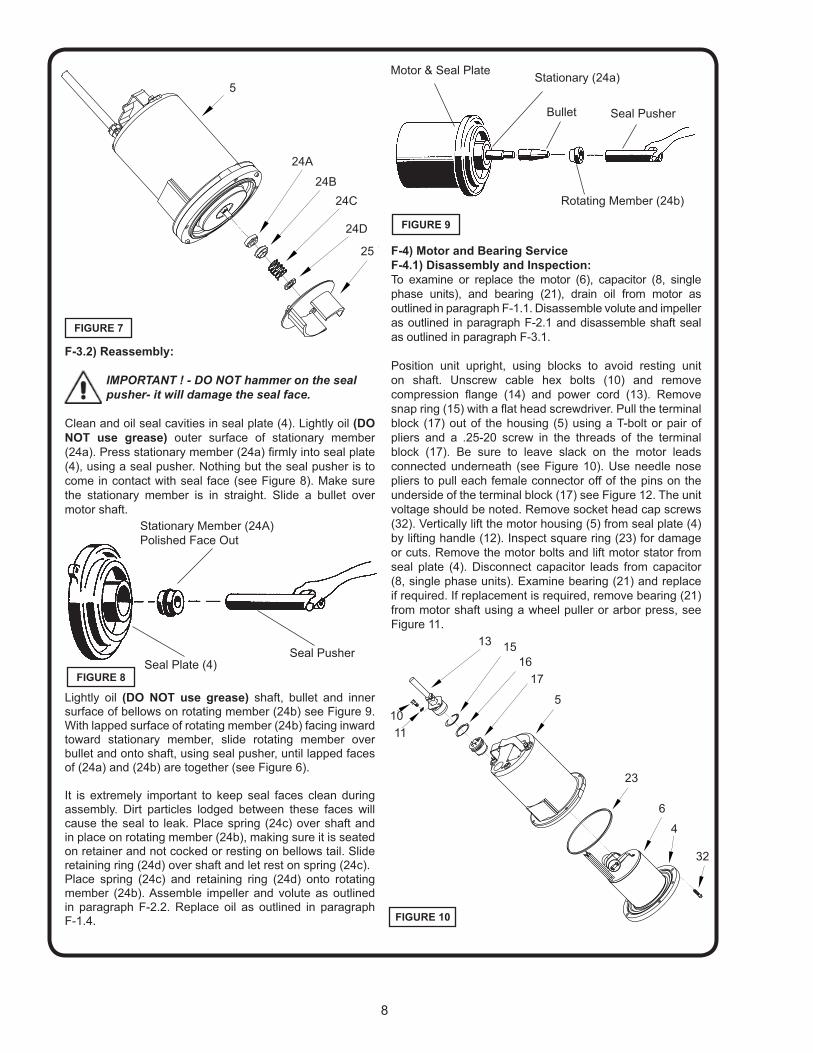
F-3.2) Reassembly:
IMPORTANT ! - DO NOT hammer on the seal pusher- it will damage the seal face.
Clean and oil seal cavities in seal plate (4). Lightly oil (DO
NOT use grease) outer surface of stationary member
(24a). Press stationary member (24a) fi rmly into seal plate
(4), using a seal pusher. Nothing but the seal pusher is to
come in contact with seal face (see Figure 8). Make sure
the stationary member is in straight. Slide a bullet over
motor shaft.
Lightly oil (DO NOT use grease) shaft, bullet and inner surface of bellows on rotating member (24b) see Figure 9. With lapped surface of rotating member (24b) facing inward toward stationary member, slide rotating member over bullet and onto shaft, using seal pusher, until lapped faces of (24a) and (24b) are together (see Figure 6).
It is extremely important to keep seal faces clean during assembly. Dirt particles lodged between these faces will cause the seal to leak. Place spring (24c) over shaft and in place on rotating member (24b), making sure it is seated on retainer and not cocked or resting on bellows tail. Slide retaining ring (24d) over shaft and let rest on spring (24c). Place spring (24c) and retaining ring (24d) onto rotating member (24b). Assemble impeller and volute as outlined in paragraph F-2.2. Replace oil as outlined in paragraph F-1.4.
F-4) Motor and Bearing Service
F-4.1) Disassembly and Inspection:
To examine or replace the motor (6), capacitor (8, single
phase units), and bearing (21), drain oil from motor as
outlined in paragraph F-1.1. Disassemble volute and impeller
as outlined in paragraph F-2.1 and disassemble shaft seal
as outlined in paragraph F-3.1.
Position unit upright, using blocks to avoid resting unit
on shaft. Unscrew cable hex bolts (10) and remove
compression fl ange (14) and power cord (13). Remove
snap ring (15) with a fl at head screwdriver. Pull the terminal
block (17) out of the housing (5) using a T-bolt or pair of
pliers and a .25-20 screw in the threads of the terminal
block (17). Be sure to leave slack on the motor leads
connected underneath (see Figure 10). Use needle nose
pliers to pull each female connector off of the pins on the
underside of the terminal block (17) see Figure 12. The unit
voltage should be noted. Remove socket head cap screws
(32). Vertically lift the motor housing (5) from seal plate (4)
by lifting handle (12). Inspect square ring (23) for damage
or cuts. Remove the motor bolts and lift motor stator from
seal plate (4). Disconnect capacitor leads from capacitor
(8, single phase units). Examine bearing (21) and replace
if required. If replacement is required, remove bearing (21)
from motor shaft using a wheel puller or arbor press, see
Figure 11.
Seal PusherSeal Plate (4)
Stationary Member (24A)
Polished Face Out
Rotating Member (24b)
Motor & Seal Plate
Bullet Seal Pusher
Stationary (24a)
FIGURE 8
FIGURE 9
5
24C
24B
25
24A
FIGURE 7
24D
FIGURE 10
6
23
32
5
4
17
16
1513
11
10

9
Check motor capacitor (8, single phase units) with an
Ohm meter by fi rst grounding the capacitor by placing a
screwdriver across both terminals and then removing
screwdriver. Connect Ohm meter (set on high scale) to
terminals. If needle moves to infi nity (∞) then drifts back,
the capacitor is good. If needle does not move or moves to
infi nity (∞) and does not drift back, replace capacitor (8).
Inspect motor winding for shorts and check resistance
values. Check rotor for wear. If rotor or the stator windings
are defective, the complete motor must be replaced.
IMPORTANT! - all parts must be clean before reassembly.
F-4.2) Reassembly:
Bearings - When replacing bearing, be careful not
to damage the rotor or shaft threads. Clean the shaft
thoroughly. Press bearing (21) on the motor shaft, position
squarely onto the shaft applying force to the inner race of
the bearing only, until bearing seats against the retaining
ring (20).
Motor - Slide lower bearing (21) and motor shaft squarely
into the seal plate (4) until bearing seats on the bottom.
Place stator over rotor, lining up motor bolts with holes in
seal plate (4). Position capacitor (8, single phase units) so
that it will lay on the opposite side of the cable entry boss of
the motor housing (5). Reconnect capacitor leads. Torque
motor tie bolts to 17 in-lbs. Set square ring (23) in grove on
seal plate (4).
F-4.3) Wiring Connections:
Check power cable (13) for cracks or damage and replace if
required (see Figure 12). Make internal wiring connections
which are independent of the terminal block as shown,
using connectors (36) as required. Do not use wire nuts.
Slip motor leads and groud wire through fi berglass sleeve.
Lower motor housing (5) down onto seal plate (4) while
aligning holes and stringing motor leads through the cord
entry bore. (Slipping cord inside a 1 ft. length of .5” conduit
makes this easier). Place socket head cap screws (32)
through seal plate (4) into motor housing (5) and torque
to 60 in-lbs. Reconnect motor and leads to the underside
of the terminal block (17), as shown in Figures 12 & 13.
Note that the pins are numbered underneath the terminal
block. Place o-ring (16) into groove in terminal block and
lubricate with dielectric oil. Press the terminal block (17)
into the housing so it seats completely below the snap ring
groove. Place snap ring (15) into groove in cord entry bore
of housing.
F-4.4) Cord Assemblies:
Power Cord - Refi ll the cooling oil as outlined in paragraph
F-1.3. Make wire connections as outlined in paragraph
F-4.3. Insert female end of cord plug into housing bore
aligning timing mark with hole in terminal block (17) see
Figure 14. Compress cord plug with compression fl ange
(14) by tightening hex bolts (10) into the housing (5).
Torque to 132 in-lbs.
Lockwasher (11)
Cap Screw (10)
Power Cord (13)
FIGURE 11
24A
4
6B
21
20
6A
89
FIGURE 12
FIGURE 14
Compression Flange (14)
Snap Ring (15)
O-ring (16)
Terminal Block (17)

10
SECTION: G REPLACEMENT PARTS
G-1) Ordering Replacement Parts:
When ordering replacement parts, ALWAYS furnish the
1. Pump serial number and date code,
2. Pump model number,
3. Pump Component number.
FIGURE 13

11
TROUBLE SHOOTINGCAUTION ! Always disconnect the pump from the electrical power source before handling.
If the system fails to operate properly, carefully read instructions and perform maintenance recommendations.
If operating problems persist, the following chart may be of assistance in identifying and correcting them:
MATCH “CAUSE” NUMBER WITH CORRELATING “CORRECTION” NUMBER.
NOTE: Not all problems and corrections will apply to each pump model.
PROBLEM CAUSE CORRECTIONPump will not run 1. Poor electrical connection, blown fuse,
tripped breaker or other interruption of power,
improper power supply.
2. Motor or switch inoperative (to isolate
cause, go to manual operation of pump).
2a. Float movement restricted.
2b. Switch will not activate pump or is defec-
tive.
3. Insuffi cient liquid level.
1. Check all electrical connections for
security. Have electrician measure current
in motor leads, if current is within ±20%
of locked rotor Amps, impeller is probably
locked. If current is 0, overload may be
tripped. Remove power, allow pump to cool,
then recheck current.
2a. Reposition pump or clean basin as
required to provide adequate clearance for
fl oat.
2b. Disconnect level control. Set ohmmeter
for a low range, such as 100 ohms full scale
and connect to level control leads. Actuate
level control manually and check to see that
ohmmeter shows zero ohms for closed switch
and full scale for open switch. (Float Switch).
3. Make sure liquid level is at least equal to
suggested turn-on point.
4. Recheck all sizing calculations to
determine proper pump size.
5. Check discharge line for restrictions,
including ice if line passes through or into
cold areas.
6. Remove and examine check valve for
proper installation and freedom of operation.
7. Open valve.
8. Check cutter for freedom of operation,
security and condition. Clean cutter and inlet
of any obstruction.
9. Loosen union slightly to allow trapped air
to escape.Verify that turn-off level of switch
is set so that the suction is always fl ooded.
Clean vent hole.
10. Remove & examine for damage. Replace
pump stator if required.
11. Repair fi xtures as required to eliminate
leakage.
12. Check pump temperature limits & fl uid
temperature.
13. Replace portion of discharge pipe with
fl exible connector.
14. Turn to automatic position.
15. Check for leaks around basin inlet and
outlets.
Pump will not turn off 2a. Float movement restricted.
2b. Switch will not activate pump or is defec-
tive.
4. Excessive infl ow or pump not properly sized
for application.
9. Pump may be airlocked.
14. H-O-A switch on panel is in “HAND” posi-
tion
Pump hums but does not run 1. Incorrect voltage
8. Cutter jammed or loose on shaft, worn or
damaged, inlet plugged.
Pump delivers insuffi cient capacity 1. Incorrect voltage.
4. Excessive infl ow or pump not properly sized
for application.
5. Discharge restricted.
6. Check valve stuck closed or installed
backwards.
7. Shut-off valve closed.
8. Cutter jammed or loose on shaft, worn or
damaged, inlet plugged.
9. Pump may be airlocked.
10. Pump stator damaged/torn.
Pump cycles too frequently or runs
periodically when fi xtures are not in use
6. Check valve stuck closed or installed
backwards.
11. Fixtures are leaking.
15. Ground water entering basin.
Pump shuts off and turns on indepen-
dent of switch, (trips thermal overload
protector). CAUTION! Pump may start
unexpectedly. Disconnect power supply.
1. Incorrect voltage.
4. Excessive infl ow or pump not properly sized
for application.
8. Cutter jammed, loose on shaft, worn or
damaged, inlet plugged.
12. Excessive water temperature.
Pump operates noisily or vibrates
excessively
4. Operating at too high a pressure.
5. Discharge restricted.
8. Cutter broken.
13. Piping attachments to buiding structure too
rigid or too loose.

12
FIGURE 15
13
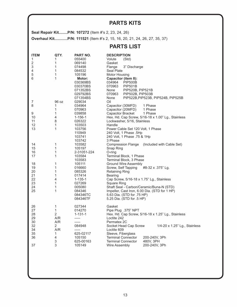
PARTS KITS
Seal Repair Kit........P/N: 107272 (Item #’s 2, 23, 24, 26)
Overhaul Kit............P/N: 111521 (Item #’s 2, 15, 16, 20, 21, 24, 26, 27, 35, 37)
PARTS LIST
ITEM QTY. PART NO. DESCRIPTION1 1 055400 Volute (Std)2 1 069140 Gasket3 1 074498 Flange 3” Discharge 4 1 084532 Seal Plate5 1 105196 Motor Housing6 1 Motor: Capacitor (item 8): 030369BS 034964 PIP500B 030370BS 070963 PIP501B 071352BS None PIP520B, PIP521B 029792BS 070963 PIP502B, PIP503B 071354BS None PIP522B,PIP523B, PIP524B, PIP525B7 96 oz 029034 Oil8 1 034964 Capacitor (30MFD) 1 Phase 1 070963 Capacitor (20MFD) 1 Phase9 1 039858 Capacitor Bracket 1 Phase10 4 1-156-1 Hex. Hd. Cap Screw, 5/16-18 x 1.00” Lg., Stainless11 8 026322 Lockwasher, 5/16, Stainless12 1 103503 Handle13 1 103756 Power Cable Set 120 Volt, 1 Phase 110949 240 Volt, 1 Phase .5Hp 103741 240 Volt, 1 Phase .75 & 1Hp 103742 3 Phase14 1 103582 Compression Flange (Included with Cable Set)15 1 105197 Snap Ring 16 1 2-31051-224 O-ring17 1 103584 Terminal Block, 1 Phase 103583 Terminal Block, 3 Phase18 1 105111 Ground Wire Assembly19 1 016660 Screw, Self Tapping #8-32 x .375” Lg.20 1 085326 Retaining Ring21 1 017414 Bearing22 4 1-135-1 Cap Screw, 5/16-18 x 1.75” Lg., Stainless23 1 027269 Square Ring24 1 005080 Shaft Seal - Carbon/Ceramic/Buna-N (STD)25 1 084346 Impeller, Cast Iron, 6.00 Dia. (STD for 1 HP) 084346TC 5.63 Dia. (STD for .75 HP) 084346TF 5.25 Dia. (STD for .5 HP)
26 1 027344 Gasket27 1 014270 Pipe Plug .375” NPT28 2 1-131-1 Hex. Hd. Cap Screw, 5/16-18 x 1.25” Lg., Stainless29 A/R ----- Loctite 24230 A/R ----- Permatex 2C32 2 084948 Socket Head Cap Screw 1/4-20 x 1.25” Lg., Stainless34 A/R ----- Loctite 60935 1 625-02117 Sleeve, Fiberglass36 4 105150 Terminal Connector 200-240V, 3Ph 3 625-00163 Terminal Connector 480V, 3PH37 3 105149 Wire Assembly 200-240V, 3Ph

14
Notes

15
Notes

D4d.1c
4/06
Supersedes 7/05
SP00D4d1c. Copyright © Grundfos CBS, Inc.
Check our worldwide offi ces at
www.paco-pumps.com
PUMPSPACO®