maintenance and repair manual - powerex · pdf filethis maintenance and repair manual covers...
TRANSCRIPT
MAINTENANCEAND
REPAIR MANUAL
SECOSV 1010, SV 1016, SV 1025 and SV 1040
C Version


Page
INTRODUCTION 2
General 2
Power Requirements 2
2.0 SERVICE AND PARTS 3
3.0 MAINTENANCE 3
3.1 Inlet Filter 3
3.2 Vacuum Relief Valve 3
3.3 Vane Inspection 3
4.0 DISASSEMBLY 3
4.1 Tools 3
4.2 Plastic Filter Cover and Filter Housing 4
4.3 Endplate, Opposite Motor Side 4
4.4 Vanes 4
4.5 Motor Cover, Plastic 4
4.6 Cylinder 4
4.7 Rotor 5
5.0 CLEANING AND INSPECTION 5
5.1 General 5
5.2 Filter Housing 5
5.3 Endplates 5
5.4 Rotor 5
6.0 ASSEMBLY 5
6.1 Rotor 5
6.2 Cylinder 6
6.3 Motor Cover, Plastic 6
6.4 Vanes 7
6.5 Endplate, Opposite Motor Side 7
6.6 Filter Cover and Plastic Cover 7
7.0 LIMITED STANDARD WARRANTY 8
Clearances and Technical Data Chart 8
Parts List 9
Assembly Drawing 10
Busch, Inc. Factory Service Centers 11
1
TABLE OF CONTENTS
We reserve the right to change the product at any time without any form of notification. The information in this pub-
lication is accurate to the best of our ability at the time of printing. Busch, Inc. will not be responsible for errors
encountered when attempting to perform tasks outlined in this publication which is copyright protected.

INTRODUCTION
This Maintenance and Repair Manual covers the Seco
Series vacuum pumps models SV 1010 C, SV 1016 C,
SV 1025 C and SV 1040 C (see Fig. 1). The Busch
Seco SV pump is an oil-free single-stage, rotary dry
vane vacuum pump.
General
All Seco SV single-stage, rotary vane pumps are direct-
driven, air-cooled, dry vane, positive displacement
pumps. They consist of a rotor mounted concentrically
on the drive shaft and positioned eccentrically in a cylin-
drical stator (see Fig. 2). The rotor has radially sliding
vanes that divide the pump chamber into sections. The
vane contact with the pump cylinder is maintained by
centrifugal force. The vanes are self-lubricating and
operate oil-free.
Power Requirements
ALL ELECTRICAL CONNECTIONS SHOULD BE
MADE BY A QUALIFIED, COMPETENT ELECTRICIAN
IN ACCORDANCE WITH ALL LOCAL AND NATIONAL
CODES!
For a copy of commonly used three phase and single
phase motor connections, see Fig. 3, 4 and 5.
2
Fig. 1 - Seco 1025 C Pump
1 2 3
1 - Gas Inlet
2 - Gas outlet (optional)
3 - Standard gas outlet w/discharge silencer valve
4 - Vacuum relief valve
4
CAUTION: Do not allow any oil, grease, liq-uid or vapor to enter the pump.
Fig. 5 - AEG Motor 115V, 1 Phase
Fig. 4 - AEG Motor 460V, 3 Phase
Fig. 3 - AEFG Motor 230V, 3 Phase
Fig. 2 - Pumping Cycles
Exhaust
Area
Intake
Area
Compression
Area
Rotation

The motor must be connected in accordance with the
electrical codes using a fused switch to protect the
motor against electrical or mechanical overloads. The
motor starter has to be set consistent with the motor
current, listed on the nameplate. For other voltage
requirements, contact the factory for motor and/or
starter information.
Correct direction of rotation is marked by an arrow on
the housing and is clockwise when looking at the motor
from the motor’s fan side.
Observe the motor fan and jog the motor briefly to make
sure it is rotating clockwise. If the motor is rotating
backwards, correct as follows:
On 3 phase motors, reverse any two leads of the three
at the power connection.
Single-phase motors are normally prewired for the cor-
rect direction. In cases where the motor is wired bi-
directional, see the schematic on the underside of the
terminal box cover for the correct direction.
2.0 SERVICE AND PARTS
Following the instructions in this manual, the technician
can completely service and repair the Seco SV pump.
A complete inventory of spare parts is maintained at
Busch, Inc. at all times. Parts will be shipped immedi-
ately upon request.
The pumps may also be shipped to the Virginia Beach,
Virginia factory or nearest authorized service center for
repair. For the location of the nearest authorized serv-
ice center, contact Busch, Inc. in Virginia Beach,
Virginia.
Busch, Inc. maintains an excellent repair department
staffed by factory-trained technicians who specialize
solely in Busch products.
3.0 MAINTENANCE
The required periodic maintenance on the Seco SV
pumps is very low. To prevent premature wear and to
insure optimum performance, it is recommended that
the following steps be performed:
3.1 Inlet Filter
The inlet filter element (Ref. 27) is located inside the fil-
ter cover (Ref. 24) at the front of the pump. Access to
the filter can be gained by removing the two socket
head cap screws (Ref. 72) retaining the outer plastic
cover (Ref. 70) and the three socket head cap screws
and copper washers (Ref. 28/29) retaining the filter
cover.
The filter cartridge should be cleaned on a weekly
basis, depending on the amount of foreign particles to
which the pump is exposed.
When cleaning the inlet filters be careful not to knock
any foreign particles that have collected inside the
housing into the pump. Replace the element if it is
extremely dirty or has been subjected to moisture, oil or
grease.
3.2 Vacuum Relief Valve
A vacuum relief valve comes installed on the most cur-
rent models. It is designed to allow a continuous flow
of air through the pump to maximize vane life. This
valve should be field adjusted to slightly exceed the
vacuum level required for the specific application.
3.3 Vane Inspection
Vane wear should be checked every six months or
more often when the pump is subjected to severe oper-
ating conditions. Vane wear can be checked (see Fig.
6) by following the first three steps of the disassembly
procedure. See the values below for wear tolerances:
Pump Model Minimum Width of Vane
SV1010 27 mm / 1.063 inch
SV1016 27 mm / 1.063 inch
SV1025 33 mm / 1.339 inch
SV1040 33 mm / 1.339 inch
4.0 DISASSEMBLY
4.1 Tools
To completely disassemble/assemble the Seco pumps,
the following tools are recommended:
CAUTION: After electrical connection hasbeen made, the rotation of the motor mustbe checked.
3
Fig. 6 - Measuring Vane Width
Allen wrenches: 5 mm
Open end wrench: 10 mm
Soft hammer: med. size, plastic or rubber
Gear puller - push-pull type
Motor shaft support tool (see Fig. 13)
Socket set with 10 mm socket
Feeler blades: .06 mm, .07 mm, .09 mm
Emery cloth: 180 grit
Flat honing stone
Cleaning agent: acetone or similar
4.2 Plastic Filter Cover and Filter Housing
Remove the plastic cover (Ref. 70) by removing the two
socket head cap screws (Ref. 72) and rubber feet (Ref.
71).
Remove the three hex head bolts and copper washers
(Ref. 28/29) and pull the filter housing (Ref. 24) off the
pump.
Pry the filter housing gasket (Ref. 22) from the opposite
motor side endplate (Ref. 18) and discard the gasket.
4.3 Endplate, Opposite Motor Side
Use an Allen wrench to unscrew the four socket head
cap screws (Ref. 19) retaining the endplate (Ref. 18).
Set the endplate aside (see Fig. 7).
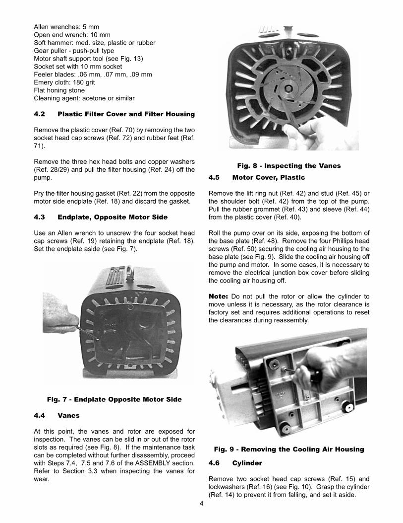
4.4 Vanes
At this point, the vanes and rotor are exposed for
inspection. The vanes can be slid in or out of the rotor
slots as required (see Fig. 8). If the maintenance task
can be completed without further disassembly, proceed
with Steps 7.4, 7.5 and 7.6 of the ASSEMBLY section.
Refer to Section 3.3 when inspecting the vanes for
wear.
4.5 Motor Cover, Plastic
Remove the lift ring nut (Ref. 42) and stud (Ref. 45) or
the shoulder bolt (Ref. 42) from the top of the pump.
Pull the rubber grommet (Ref. 43) and sleeve (Ref. 44)
from the plastic cover (Ref. 40).
Roll the pump over on its side, exposing the bottom of
the base plate (Ref. 48). Remove the four Phillips head
screws (Ref. 50) securing the cooling air housing to the
base plate (see Fig. 9). Slide the cooling air housing off
the pump and motor. In some cases, it is necessary to
remove the electrical junction box cover before sliding
the cooling air housing off.
Note: Do not pull the rotor or allow the cylinder to
move unless it is necessary, as the rotor clearance is
factory set and requires additional operations to reset
the clearances during reassembly.
4.6 Cylinder
Remove two socket head cap screws (Ref. 15) and
lockwashers (Ref. 16) (see Fig. 10). Grasp the cylinder
(Ref. 14) to prevent it from falling, and set it aside.
4
Fig. 7 - Endplate Opposite Motor Side
Fig. 8 - Inspecting the Vanes
Fig. 9 - Removing the Cooling Air Housing

Note: The heads of the screws are located down
inside the cylinder cavity.
4.7 Rotor
To remove the rotor (Ref. 5), screw a 5 mm cap screw
into a threaded hole in the face of the rotor. Use a long
bar or screwdriver between the cap screw and socket to
prevent the rotor (Ref. 5) from turning while you
unscrew the M6 cap screw (see Fig. 11). Set the cap
screw, lockwasher (Ref. 10) and tightening disk (Ref. 8)
aside.
Install a bar puller on the rotor (see Fig. 12). Advance
the puller until the rotor is loose on the shaft and can be
removed from the shaft.
5.0 CLEANING AND INSPECTION
5.1 General
Use compressed air to blow off all parts. When neces-
sary, soak the parts in a degreasing solution, agitate
and scrub to remove any grimy residue, and then rinse
and blow dry.
Clean off any surface scale.
Inspect the sealing surfaces. Use a honing stone to
polish out nicks and scratches.
5.2 Filter Housing
Use compressed air to blow off the filter element (Ref.
27). Do not damage the pleats. If the element materi-
al looks clogged, replace it. Inspect the filter spring for
corrosion or damage. Check the silencer valve (Ref.
32) for operation and build-up of residue. Check the
vacuum relief valve for any build up of dust or particu-
late.
5.3 Endplates
Clean the intake and exhaust cavities in the endplate
(Ref. 18).
5.4 Rotor
Clean the vane slots. Check the vane movement in the
slots. The vanes must drop freely in the slots.
6.0 ASSEMBLY
6.1 Rotor
Set the motor up on end with the fan side of the shaft
Fig 10 - Cylinder Removal
Screws
5
CAUTION: Do not pull the rotor from themotor shaft by exerting force on any sur-face other than the rotor and the end of theshaft. Alternate methods could damage themotor bearings.
Fig. 11 - Rotor Locking Screw
Fig. 12 - Rotor Removal
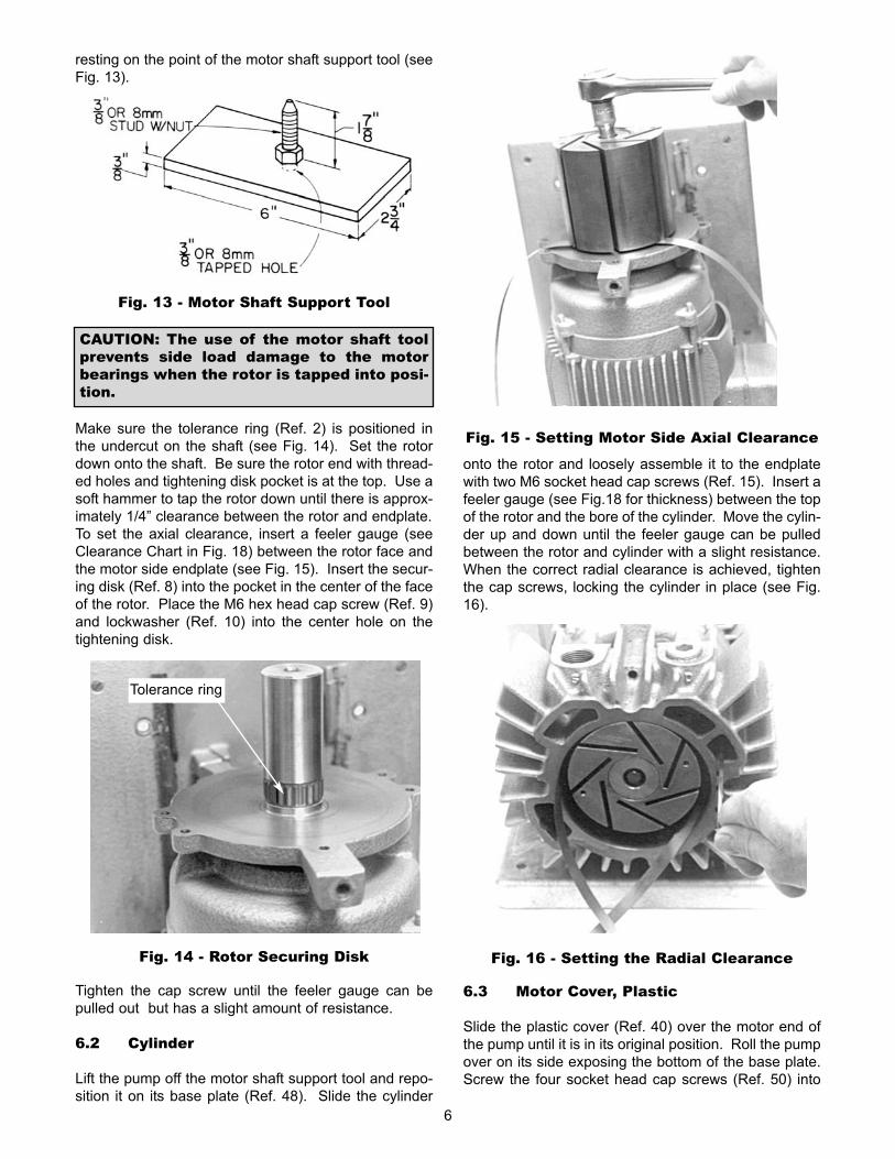
resting on the point of the motor shaft support tool (see
Fig. 13).
Make sure the tolerance ring (Ref. 2) is positioned in
the undercut on the shaft (see Fig. 14). Set the rotor
down onto the shaft. Be sure the rotor end with thread-
ed holes and tightening disk pocket is at the top. Use a
soft hammer to tap the rotor down until there is approx-
imately 1/4” clearance between the rotor and endplate.
To set the axial clearance, insert a feeler gauge (see
Clearance Chart in Fig. 18) between the rotor face and
the motor side endplate (see Fig. 15). Insert the secur-
ing disk (Ref. 8) into the pocket in the center of the face
of the rotor. Place the M6 hex head cap screw (Ref. 9)
and lockwasher (Ref. 10) into the center hole on the
tightening disk.
Tighten the cap screw until the feeler gauge can be
pulled out but has a slight amount of resistance.
6.2 Cylinder
Lift the pump off the motor shaft support tool and repo-
sition it on its base plate (Ref. 48). Slide the cylinder
onto the rotor and loosely assemble it to the endplate
with two M6 socket head cap screws (Ref. 15). Insert a
feeler gauge (see Fig.18 for thickness) between the top
of the rotor and the bore of the cylinder. Move the cylin-
der up and down until the feeler gauge can be pulled
between the rotor and cylinder with a slight resistance.
When the correct radial clearance is achieved, tighten
the cap screws, locking the cylinder in place (see Fig.
16).
6.3 Motor Cover, Plastic
Slide the plastic cover (Ref. 40) over the motor end of
the pump until it is in its original position. Roll the pump
over on its side exposing the bottom of the base plate.
Screw the four socket head cap screws (Ref. 50) into
Fig. 13 - Motor Shaft Support Tool
CAUTION: The use of the motor shaft toolprevents side load damage to the motorbearings when the rotor is tapped into posi-tion.
Tolerance ring
Fig. 14 - Rotor Securing Disk
Fig. 15 - Setting Motor Side Axial Clearance
Fig. 16 - Setting the Radial Clearance
6

the base plate, through the two rubber gaskets (Ref. 47)
and into the plastic cover. Roll the pump onto its base
plate and replace the electrical junction box cover.
Insert the rubber bushing (Ref. 43), spacer (Ref. 46)
and sleeve into the top of the plastic cover. On the
SV1010 and SV1016, screw the socket head cap screw
(Ref. 42) into the pump. On the SV1025 and SV1040,
screw the stud (Ref. 45) and eye bolt (Ref. 42) into the
pump (see Fig. 17).
6.4 Vanes
Slide the vanes (Ref. 6) into the vane slots. Make sure
the radius edge is matched to the contour of the cylin-
der bore (see Fig. 2).
6.5 Endplate, Opposite Motor Side
Install the opposite motor side endplate (Ref. 18) to the
cylinder. Secure with four M6 socket head cap screws
and lockwashers (Ref.19/20).
6.6 Filter Cover and Plastic Cover
Install a new filter cover gasket (Ref. 22). Do not use
the old gasket as it does not seal well when reused.
Position the filter element (Ref. 27), retaining spring
(Ref. 25) and filter cover (Ref. 24) in place and secure
with three socket head cap screws and copper washers
(Ref. 28/29).
Position the two rubber feet (Ref. 71) against the filter
cover and slide the plastic cover (Ref. 70) over the filter
cover, sandwiching the rubber feet between the filter
cover and plastic cover while tightening the two socket
head cap screws.
7.0 LIMITED STANDARD WARRANTY
Busch, Inc. warrants that all products furnished by it are
free from defects in material and workmanship at the
time of shipment for a period of 18 months from the
date of shipment, or 12 months from the date of instal-
lation, whichever occurs first. Claims must be made
during that period and are limited to the replacement or
repair of parts claimed to be defective.
In the case of components purchased by Busch, Inc.,
such as starters, controls, mechanical seals, motors,
couplings, etc., the warranty of that manufacturer will be
extended to the purchaser in lieu of any warranty by
Busch, Inc. The replacement of wear items including,
but not limited to, seals, bearings, couplings, exhaust
cover gaskets, etc., made in connection with normal
service, are not covered by this Warranty.
The Limited Standard Warranty is valid only when the
product has been properly installed, used in a normal
manner, and serviced according to the operating man-
ual. This warranty shall not extend to products that
have been misused, neglected, altered, or repaired
without factory authorization during the warranty period.
We highly recommend the use of Busch parts to
achieve documented performance and efficient opera-
tion. The use of parts other than Busch could limit the
life expectancy of the equipment and could void any
warranties if they are the cause of any damage.
Operating conditions beyond our control such as
improper voltage, excessive ambient temperatures, or
other conditions that would affect the performance or
life of the product will also cause the warranty to
become void.
Permission to return parts for warranty repair must be
obtained, and all returns must be prepaid to the factory.
If, after examination, the product or part is found to be
defective, it will be repaired or replaced on a no-charge
basis and returned, FOB the factory. If it is determined
that the Warranty has not been breached by Busch,
Inc., then the usual charges for repair or replacement
will be made, FOB the factory. Parts or products that
are obsolete or those made to special order are not
returnable.
This Limited Standard Warranty applies only to the
above and is for the period set forth. Busch, Inc.'s max-
imum liability shall not, in any case, exceed the contract
price for the product, part, or component claimed to be
defective; and Busch, Inc. assumes no liability for any
special, indirect, or consequential damages arising
from defective equipment.
THERE ARE NO WARRANTIES IMPLIED OREXPRESSED THAT EXTEND BEYOND THOSECONTAINED IN THIS LIMITED STANDARDWARRANTY.
Note: For extended warranties on your new equipment
contact Busch Headquarters at 1-800-USA-PUMP.
7
Fig. 17 - Lift Ring

Clearances Chart
Note: All dimensions are in millimeters
Technical Data Chart
Fig. 18 - Clearances and Technical Data8

9
Ref. Description Qty.No.
1 Motor 1
2 Tolerance ring 1
5 Rotor 1
6 Vane 7
8 Alignment disk 1
9 Hex head cap screw 1
10 Lock washer 1
13 Plug 1
14 Cylinder 1
15 Socket head cap screw 2
16 Lock washer 2
17 Plug 1
18 Endplate 1
19 Socket head cap screw 4
20 Lock washer 4
22 Filter cover gasket 1
24 Filter cover 1
25 Spring for retaining filter 1
27 Filter cartridge 1
28 Socket head cap screw 3
29 Copper gasket 3
30 Socket head plug 1
32 Silencer valve 1
39 Cooling fan 1
40 Plastic cover for motor 1
Ref. Description Qty.No.
42* Eye bolt 1
42** Skt. hd. cap screw 1
43 Rubber lifting eye bushing 1
44 Washer 1
45 Stud (SV1025/SV1040 only) 1
46 Lifting eye spacer 1
47 Rubber mounting gasket 2
48 Base plate 1
49 Threaded insert for base 4
50 Socket head cap screw 4
51 Flat washer 4
54 Socket head cap screw 2
55 Flat washer 2
58 Rubber foot 4
59 Foot sleeve 4
61 Blind plug 1
62 Nameplate 1
63 Nameplate screw 2
70 Plastic cover for filter cover 1
71 Rubber foot 2
72 Socket head cap screw 2
* For the SV1025 and SV1040 only
** For the SV1010 and SV1016 only
Parts List

SV
1025 C
Show
n
Note
: V
acuum
relie
f valv
e n
ot
show
n
Fig. 19 - Assembly Drawing10

11
Busch Inc. Factory Service Centers
California Illinois
13826 Struikman Road 430 Windy Point Drive
Cerritos, CA 90703 Glendale Heights, IL 60139
Phone (562) 926-8422 Phone (630) 545-1310
Fax (562) 926-7262 Fax (630) 545-1384
[email protected] [email protected]
New Jersey Puerto Rico
39 Davis Street 420 E Street, Suite 4
South Plainfield, NJ 07080 Minillas Industrial Park
Phone (908) 561-3233 Bayamon, PR 00959-1901
Fax (908) 561-3909 Phone (787) 798-5045
[email protected] Fax (787) 798-5033
Texas Virginia
15411 Vantage Pkwy W., Suite 216 516 Viking Drive
Houston, TX 77032 Virginia Beach, VA 23452
Phone (281) 449-2381 Phone (757) 463-7800
Fax (281) 449-2383 Fax (757) 463-7407


P/N 0872.915.364
Revision 01/06
Busch, Inc.
516 Viking Drive
Virginia Beach, Virginia 23452
Phone: (757) 463-7800
FAX: (757) 463-7407