mainframe application program planning and design
TRANSCRIPT

MAINFRAME
APPLICATION PROGRAM PLANNING AND DESIGN
March 2006

Number: 11.01 Effective: 03/03/2006
Mainframe Program Planning and Design Page i Rel: March 03, 2006
TABLE OF CONTENTS
1 INTRODUCTION .................................................................................................................................................. 1 1.1 PURPOSE .................................................................................................................................................. 1 1.2 SCOPE ...................................................................................................................................................... 1 1.3 APPLICABILITY .......................................................................................................................................... 2 1.4 REFERENCE .............................................................................................................................................. 2 1.5 SUGGESTIONS AND COMMENTS ................................................................................................................. 2
2 PROGRAM PLANNING ....................................................................................................................................... 3 2.1 PROGRAM SPECIFICATION FORMS ............................................................................................................. 4 2.2 NAMING CONVENTIONS ............................................................................................................................. 5 2.3 PAGE SIZE VERIFICATION .......................................................................................................................... 5 2.4 CONSOLE MESSAGE ................................................................................................................................. 5 2.5 JOB RE-EXECUTION CAPABILITIES ............................................................................................................ 6
2.5.1 AUTOMATIC JOB RERUN .............................................................................................................. 6 2.5.2 JOB STREAM RESTART ................................................................................................................ 6
2.6 DIRECT ACCESS STORAGE DEVICE ........................................................................................................... 6 2.6.1 REQUESTING DIRECT ACCESS STORAGE ..................................................................................... 7 2.6.2 PERMANENT DATA SETS .............................................................................................................. 7 2.6.3 TEMPORARY DATA SETS.............................................................................................................. 7
2.7 MAGNETIC (REEL OR CARTRIDGE) TAPE ................................................................................................... 7 2.7.1 REQUESTING MAGNETIC REEL/CARTRIDGE TAPE ......................................................................... 8 2.7.2 MAGNETIC TAPE JOB SUBMISSION PROCEDURES ......................................................................... 8 2.7.3 STORING MAGNETIC REEL/CARTRIDGE TAPE ............................................................................... 8
2.8 GENERATION DATA GROUP ....................................................................................................................... 9 2.9 COMPUTER OPERATING SYSTEM PROCEDURES ......................................................................................... 9
2.9.1 CATALOGUED PROCEDURES ........................................................................................................ 9 2.9.2 COBOL FOR MVS PROCEDURES .............................................................................................. 10 2.9.3 COBOL WITH CICS PROCEDURES ............................................................................................ 10 2.9.4 PL/I PROCEDURES .................................................................................................................... 10 2.9.5 IN-STREAM PROCEDURES .......................................................................................................... 10
2.10 DATA FLOW DIAGRAM ............................................................................................................................. 11 2.11 ACCESS DATA RESOURCE ...................................................................................................................... 12
3 PROGRAM DESIGN .......................................................................................................................................... 12 3.1 PROGRAM STRUCTURE ........................................................................................................................... 13 3.2 PROGRAM FUNCTION STRUCTURE CHART ............................................................................................... 13 3.3 STRUCTURED PROGRAMMING ................................................................................................................. 14
3.3.1 PROGRAM DESIGN ITERATION VARIATION ................................................................................... 16 3.3.2 CASE LOGIC SELECTION STRUCTURES ..................................................................................... 17 3.3.3 “GO TO” STATEMENTS AND LABELS .......................................................................................... 17 3.3.4 PROGRAM FUNCTION SEGMENTATION ........................................................................................ 18 3.3.5 PROGRAM CODE INDENTATION .................................................................................................. 19 3.3.6 ESTABLISH INDENTATION CONVENTIONS .................................................................................... 20
3.4 FLOWCHART LOGIC ................................................................................................................................. 20 3.5 PSUEDO-CODE LOGIC ............................................................................................................................. 20 3.6 EFFICIENCY CONSIDERATIONS ................................................................................................................. 21 3.7 FINE TUNE PROGRAM .............................................................................................................................. 21 3.8 REFERENCES .......................................................................................................................................... 22
Number: 11.01 Effective: 03/03/2006
Mainframe Program Planning and Design Page ii Rel: March 03, 2006
4 PROGRAMMING AND TESTING ...................................................................................................................... 22 4.1 PROGRAMMING LANGUAGES ................................................................................................................... 23 4.2 UTILITY SOFTWARE ................................................................................................................................. 23 4.3 PROGRAMMER PRODUCTIVITY TOOLS ..................................................................................................... 23 4.4 PROGRAM TESTING ................................................................................................................................. 23 4.5 PROGRAM DOCUMENTATION ................................................................................................................... 24
5 PROGRAM IMPLEMENTATION ....................................................................................................................... 25 5.1 SOURCE PROGRAM STORAGE ................................................................................................................. 25 5.2 LOAD MODULE PROGRAM STORAGE ....................................................................................................... 25 5.3 CONVERT FROM TEST TO PRODUCTION ................................................................................................... 25 5.4 USER DOCUMENTATION .......................................................................................................................... 25 5.5 OPERATIONS DOCUMENTATION ............................................................................................................... 25 5.6 SCHEDULE TEST JOB .............................................................................................................................. 26 5.7 PRODUCTION JOB STREAM ..................................................................................................................... 26
5.7.1 FROM TEST TO PRODUCTION ............................................................................................... 26 5.7.2 RELEASE EDPD.LINKLIBT SPACE ........................................................................................... 26
6. APPENDIX
Structured Program Development Convert Data-Flow-Diagram To Pseudo-Code
Number: 11.01 Effective: 03/03/2006
Department of Accounting and General Services Information and Communication Services Division Information Technology Standards
Mainframe Program Planning and Design Page 1 Rel: March 03, 2006 (draft#5)
1 INTRODUCTION This document contains the State of Hawaii Executive Branch of government’s established standards, conventions, procedures and guidance for the Data Processing Systems Analyst (DPSA) who must analyze, design and develop application system and application design specifications. This document is also useful for the computer programmer (CP) who needs to construct application programs from the application system design specifications. Consistent standardized central-site mainframe-based application program planning and design processes, specifications and conventions will provide the project DPSA with a predictable and uniform approach for planning, designing, and setting up application resources, specifications, and information.
1.1 Purpose This document provides a common basis for planning, organizing, developing, coordinating, and designing standardized application program resources, environments and specifications. It presents the State of Hawaii conventions and guidance for data processing personnel who must develop applications systems, or work with application program specifications stored in any State of Hawaii Executive Branch main-frame computer host system. 1.2 Scope The scope of this document is limited to the identification, procurement, and scheduling of resources and forms that should be considered during the planning and development of: a. Computer stored application system design and program specifications,
and b. Supplemental data and information resources needed for the development
of application specifications. This document will provide a general description of when and how to present information required for enabling application program documentation. This document does not address the actual processes and procedures for application systems analysis, design, development, construction, testing, installation, migration, or implementation.

Number: 11.01 Effective: 03/03/2006
Department of Accounting and General Services Information and Communication Services Division Information Technology Standards
Mainframe Program Planning and Design Page 2 Rel: March 03, 2006 (draft#5)
1.3 Applicability This document represents the State of Hawaii Executive Branch’s standards, conventions, and guidelines for the planning, development, and designing of resources and environment for an application system. This document is intended to be used by both State agencies with data processing personnel and vendors and contractors working for the State of Hawaii. Because this document is intended to be used by application development personnel during the planning, development, and designing of applications in different programming languages, words such as “should,” “avoid,” “minimize,” “try,” or “encouraged” were included in the text. These permissive words are intended to provide guidance for people who are enhancing existing programs and systems. But for any new application, or for major revisions, these words shall be interpreted in their absolute sense of “will,” “do not,” or “shall.” 1.4 Reference Throughout this document, the phrase “Standards Document 07.05” will refer to the statewide information technology (IT) standards “Operations Production Job Documentation” document. The term “Production Services Branch” or “PSB” refers to the Department of Accounting and General Services (DAGS) Information and Communication Services Division (ICSD) central site computer operational “Production Services Branch.” And the term “Applications Branch” refers to the DAGS ICSD Client Services Branch (CSB). 1.5 Suggestions and Comments Any State of Hawaii Information Technology (IT) Standards document, reference manual or users guide mentioned in this document are available through the departmental user agency data processing coordinator (DP Coordinator). Many IT Standards documents may also be accessible on-line via the Internet by clicking on Information Technology Standards in the left side-bar of the ICSD home page at:
http://www.hawaii.gov/icsd/

Number: 11.01 Effective: 03/03/2006
Department of Accounting and General Services Information and Communication Services Division Information Technology Standards
Mainframe Program Planning and Design Page 3 Rel: March 03, 2006 (draft#5)
Fillable Statewide Forms are also available via the State of Hawaii web page by first clicking on Government in Hawaii followed by clicking on Forms Central. Any comment, recommendation, proposal, or suggestion regarding the contents or presentation of this IT Standards document may be sent either via internet email to [email protected], or in writing to:
Information and Communication Services Division Project Planning and Management Office 1151 Punchbowl Street, B10 Honolulu, Hawaii 96813-3024
2 PROGRAM PLANNING The data processing systems analyst (DPSA) for an application system or project is responsible for providing the computer programmer with the application design forms, charts, tables and other support documentation necessary for the successful development, construction, testing, and/or integration of computer programs for an application system. When planning for the implementation of an application system, it is important to have a detail system data-flow diagram that shows the relative position of data and/or information moving in and out of each application program function needed to satisfy the requested application system requirements. The overall system data-flow diagram identifies and specifies the required input data and the required output information from each application program function in the application system. This overview system data-flow diagram should be carefully reviewed and discussed by members of the application project team and the requesting user before developing the designed program functions. This will familiarize the assigned systems analysts and computer programmers with the processing environment that the programs will be required to function in. This overview system data-flow diagram shows all the identified and specified programs, input data files, tables, output files, reports, interfaces both to and from the custom programs in the system, and interfacing operating system utilities, or any other supporting software. For each input entity in the system data-flow diagram related to each program, it is

Number: 11.01 Effective: 03/03/2006
Department of Accounting and General Services Information and Communication Services Division Information Technology Standards
Mainframe Program Planning and Design Page 4 Rel: March 03, 2006 (draft#5)
necessary to review the detailed field descriptions, characteristics and attributes of fields, records and tables. It is also necessary to review the detailed data element layout and definitions for any file, record, transaction, parameter, and any control statement entered or generated for each program that are specified on the program specification forms.
2.1 Program Specification Forms The State of Hawaii Executive Branch has many forms for the DPSA to use in developing detailed system’s external and internal application system specifications. The state has adopted an application system development methodology, named SDM/Structured. This methodology identifies eight different phases to be considered and used during the actual development of any application system for the State of Hawaii. The application systems development phases (in order for consideration) are: a. SRD: System Requirements Definition, b. SDA: System Design Alternatives, c. SES: System External Specifications, d. SIS: System Internal Specifications, e. CON: Constructing Programs, f. TST: Test and Debug Programs, g. CNV: Convert and/or Migrate System, h. IMPL: Implement and Install System, and i. POST: Post-Implementation Review/Assessment. This document assumes that the detail specifications for the requested application system has been defined in such detail, whereby the needs, scope, constraints, conceptualizations, and alternatives have been documented and agreeded upon between the application requester and the mainframe computer system implementation team-leader. This document focuses on the methodology’s SES (systems external specifications) phase, and the SIS (systems internal specifications) phase. This document will only briefly touch on the application construction, testing, conversion, and implementation phases. This document may briefly discuss or describe the appropriate use of statewide
Number: 11.01 Effective: 03/03/2006
Department of Accounting and General Services Information and Communication Services Division Information Technology Standards
Mainframe Program Planning and Design Page 5 Rel: March 03, 2006 (draft#5)
standardized forms that were selected and designed for use during the SES and SIS phases. The selection of a form is determined by the unique criteria and situations of the system and the program. The Internet forms found at http://www4.hawaii.gov/StateForms/ that must be used to document and describe applications developed for the State of Hawaii Executive Branch are: a. ICSD-101 ICSD S/1 Request for Service b. ICSD-120 File Description c. ICSD-121 Data Set Description Sheet d. ICSD-123 Program Specification e. ICSD-137 Operations Documentation Checklist f. ICSD-145 Specifications for Xerox Electronic Printing System g. ICSD-186 Control Statement Layout h. SDM-1100 SDM/Structured General Documentation Form i. SDM-1101 SDM/Structured Chart or Table Form j. SDM-1886 SDM/Structured Production Schedule k. SDM-1890 SDM/Structured File Retention & Disposition l. SDM-1895 SDM/Structured Job Instructions m. SDM-1897 SDM/Structured ReRun/ReStart Procedures 2.2 Naming Conventions Any job name, step name, data set name, source module, load module, include module, and program name must conform to the established naming conventions found in the State’s “Job Control Language Standards,” information technology (IT) standards document 11.02. 2.3 Page Size Verification A line-counting feature should be designed to control the page layout of printed reports. For COBOL programs, DO NOT use the Report Writer facility, instead, use the standard COBOL command “C01”, Top-of-Page, special name to control the page size. And for PL/I programs, the ENDPAGE conditional control block should be used for page control. 2.4 Console Message The only text that a program may send to the computer operator’s console must

Number: 11.01 Effective: 03/03/2006
Department of Accounting and General Services Information and Communication Services Division Information Technology Standards
Mainframe Program Planning and Design Page 6 Rel: March 03, 2006 (draft#5)
be related to the status of a program’s execution. Any other text to be sent to the operator’s console must be approved by the ICSD Production Services Branch (PSB) Manager. 2.5 Job Re-Execution Capabilities As much as possible, application job streams will be designed so that they can be resubmitted by the ICSD PSB control clerk. If the job stream cannot be resubmitted at any time, the aborted job stream will be returned to the submitter without any action by ICSD PSB. For jobs that can be restarted at a step after the first job step, restart points must be documented in detail in the production job operation’s documentation. Any recovery procedure to be followed by the ICSD PSB control clerk before a job can be resubmitted must be explicitly defined in the production job operation’s documentation.
2.5.1 Automatic Job Rerun Jobs that can be rerun at any time must not alter the computer operating system catalog. These jobs are typically edit, query, extract, or reports only runs. 2.5.2 Job Stream Restart There are two ways to define a restart for a job stream: a. RESTART parameter in the JOB statement to resume a job
execution at the beginning of a job step, which is the preferred method, and
b. Resume a job at CHECKPOINTS to restart in mid-job step is not
recommended. If printed output should not be recreated or regenerated; or if output data is critical to the restart procedure, the output report-or-data should be written to a temporary disk storage data set, and the report-printed or data-saved at the end of the job stream.
2.6 Direct Access Storage Device Direct access storage device (DASD) is a necessary resource for the storage

Number: 11.01 Effective: 03/03/2006
Department of Accounting and General Services Information and Communication Services Division Information Technology Standards
Mainframe Program Planning and Design Page 7 Rel: March 03, 2006 (draft#5)
and retrieval of an organization’s data and information. ICSD has a limited number of data storage devices that must be shared by all Executive Branch agencies.
2.6.1 Requesting Direct Access Storage The ICSD Systems Services Branch (SSB) is responsible for managing the State of Hawaii Executive Branch’s limited direct access storage devices. The ICSD SSB is responsible for allocating and making available any permanent (“Production”) or temporary (“Test”) direct access storage for applications on shared storage devices. The application program’s DPSA is responsible for filling out form ICSD T-121, “Data Set Description Sheet,” and sending it to ICSD SSB to request direct access storage space allocation for any permanent disk storage area needed for an application. 2.6.2 Permanent Data Sets All permanent or production applications will have their data stored on shared storage devices that are managed and controlled by ICSD SSB. The back-up and maintenance of permanent application data sets are determined by the agency owner of the data. The data owner is responsible for determining how often and who runs the backup jobs for their application systems. 2.6.3 Temporary Data Sets Temporary data set space will be purged on a regular basis, usually three weeks after its creation. For a program that requires data to be saved during the development and testing processes, the computer programmer should allocate data set space on temporary DASD by using the JCL parameter: “UNIT=3390,VOL=SER=XNZ001”. Should a program require large amounts of storage, that is, in excess of four cylinders, the project DPSA must make arrangements with ICSD SSB.
2.7 Magnetic (Reel or Cartridge) Tape

Number: 11.01 Effective: 03/03/2006
Department of Accounting and General Services Information and Communication Services Division Information Technology Standards
Mainframe Program Planning and Design Page 8 Rel: March 03, 2006 (draft#5)
Magnetic (reel or cartridge) tape media storage devices may be used for the storage and retrieval of an organization’s data, or for the long-term archival storage of data. There are a limited number of drives for magnetic (reel or cartridge) tapes at the DAGS ICSD central computing site that must be shared by all user agencies. Any job requesting a magnetic reel tape drive must have the prior approval of the ICSD PSB Scheduler. Any job that needs more than three (3) tape drives must have the prior approval of the ICSD PSB Scheduler.
2.7.1 Requesting Magnetic Reel/Cartridge Tape The project DPSA must refer to the “Production Job Operations Documentation,” IT standards document 07.05 and to the “Tape Library Management Services (TLMS)” IT standards document for the appropriate forms and procedures to request magnetic tape media for any tape-oriented system. 2.7.2 Magnetic Tape Job Submission Procedures Any test job requesting reel/cartridge tape mounts must use a special job class code. The appropriate job execution class code for the job statement may be found in the “Job Control Language (JCL) IT standards document 11.02. Any test job requiring reel/cartridge user tape mounts must be submitted to the ICSD PSB scheduling and control unit in an appropriate pouch with an ICSD Job Route card secured to the outside of the pouch. 2.7.3 Storing Magnetic Reel/Cartridge Tape ICSD PSB has very limited space for the storage of magnetic tape media. Tape reels may be stored in the ICSD PSB tape library, and tape cartridges may be stored in the TLMS silo. Only jobs that require frequent access to reel or cartridge tapes may be stored in ICSD PSB areas. The project manager must ask the ICSD PSB Supervisor for space on the tape racks or silo. The storage and security of the magnetic tape reel or cartridge that are not stored at ICSD PSB are the responsibility of the user agency.

Number: 11.01 Effective: 03/03/2006
Department of Accounting and General Services Information and Communication Services Division Information Technology Standards
Mainframe Program Planning and Design Page 9 Rel: March 03, 2006 (draft#5)
2.8 Generation Data Group A generation data group of magnetic tape cartridges that are under the control of the tape library management system (TLMS) is highly recommended for application systems. The generation data group provides a very good mechanism for data auditing, history, backup, and recovery for the application system. Procedures for establishing a generation data group may be found in the State information technology standards document 11.02 Job Control Language (JCL). 2.9 Computer Operating System Procedures The system developer communicates with the computer operating system, computer job scheduler, and computer programs through job control language (JCL) statements. The State’s central computer has operating system program utility procedures that can compile, load, link-edit and execute application programs in various application program languages so that they are understandable to the mainframe computer operating system. The common ICSD supported utility procedures are stored and cataloged in the library partitioned data set, “EDPD.PROCLIBU”. These catalogued program language procedures may be used to compile, debug, link-edit, and execute application programs in either the batch or on-line environment. There is a listing of the available operating system utility “PROCs” in the JCL, IT standards document 11.02.
2.9.1 Catalogued Procedures The default parameters for the cataloged procedures for supported programming languages were established by ICSD SSB: a. to provide optimal effective controls for the computer job scheduler to
regulate the execution of job steps, b. to retrieve and determine the disposition of data set allocating
resources, and c. to communicate consistently and effectively with computer operators
and computer programmers.

Number: 11.01 Effective: 03/03/2006
Department of Accounting and General Services Information and Communication Services Division Information Technology Standards
Mainframe Program Planning and Design Page 10 Rel: March 03, 2006 (draft#5)
2.9.2 COBOL for MVS Procedures ICSD SSB has established cataloged procedures to be used for applications in a COBOL for MVS environment. ICSD SSB has also included procedures to support initial syntax checking; logic checking; and test and production procedures to support the CICS (controlled interactive command systems) environment. Names of the procedures and their functions are presented in the “COBOL for MVS Standards and Conventions,” IT standards document 11.10. ICSD also has procedures that use software product from Computer Associates, the CA-OPTIMIZER. These procedures should be used to debug and test the logic of the COBOL application program. The names of these procedures and their functions are presented in the “COBOL CA-Optimizer Procedures,” IT standards document 11.01.06. 2.9.3 COBOL with CICS Procedures COBOL programs developed for interactive applications using IBM CICS may be processed via cataloged utility procedures. The names of these procedures and their functions are presented in the “COBOL for MVS Standards and Conventions,” IT standards document 11.10. 2.9.4 PL/I Procedures ICSD has cataloged utility procedures for applications developed in an IBM PL/I environment. These procedures are for the users of the IBM OS PL/I Level F and IBM OS PL/I Optimizing Compiler. These versions of the IBM OS PL/I Compiler installed at ICSD are not supported by IBM and are available to users on an as-is basis. The names of these procedures and their functions are presented in the “PL/I Standards and Conventions,” IT standards document 11.16. 2.9.5 In-Stream Procedures

Number: 11.01 Effective: 03/03/2006
Department of Accounting and General Services Information and Communication Services Division Information Technology Standards
Mainframe Program Planning and Design Page 11 Rel: March 03, 2006 (draft#5)
In-stream procedures are used like system cataloged procedures. The difference is that cataloged procedures are members of a partitioned data set, and the statements for the in-stream procedure are placed in the job input stream after the JOB statement. In-stream procedure specifications should be used to test proposed production job streams. They may also be used for limited-use utility procedures. Tested in-stream procedures may be cataloged in the partitioned data set (library) established for an agency, or in the shared “EDPD.PROCLIBA” library for use at a later time in production job streams. Any control statement needed for any catalogued procedures must already exist, and may be cataloged in a partitioned data set established for an agency, or catalogued in “EDPD.PARMLIB” for use at a later time. The JCL standards document 11.02 has a more in-depth discussion on the topic “Using In-Stream and Cataloged Procedures.”
2.10 Data Flow Diagram The data flow diagram (DFD) is a graphical technique for defining the data elements and the flow of the data elements into and out of the transformation processes (programs) that make up the application system. Any data element or entity identified as necessary for entering and/or exiting a transformation process for the system, to provide information, must be catalogued in a data dictionary associated with the application system. The DFD is a network of graphical symbols that shows the flow of data elements, stores of grouped data, data process transformations, and data source and/or destinations. The goal of the DFD is to serve as a visual model (or prototype) to demonstrate understanding of terms, processes, and procedures for clearer understanding between both the user requester and the technical systems developer. The DFD is a logical representation of WHAT a proposed system or program would do, and not a physical model of HOW nor WHEN the system or program would do it. The DFD is not an information tool for specifying process sequences nor for defining branch logic events controls.

Number: 11.01 Effective: 03/03/2006
Department of Accounting and General Services Information and Communication Services Division Information Technology Standards
Mainframe Program Planning and Design Page 12 Rel: March 03, 2006 (draft#5)
The DFD model uses four basic symbols: a. a square (to identify an external entity or influencing system or variable); b. an arrow (to show the direction of the flow of data); c. a rectangle (to identify a data store, table, or file); and d. a circle (to describe a transformation process). 2.11 Access Data Resource The project manager is responsible for verifying that any person who is to develop, support, service and/or maintain the application system has the appropriate and necessary access rights. Typical resources that these people should have defined access privileges are: a. Project management system (PMS) codes b. Mainframe on-line time share option (TSO) c. Mainframe project CICS-region, data-base and data dictionary d. Mainframe information management problem tracking (InfoSys) software It is the project manager DPSA who is responsible for contacting ICSD SSB when anyone on the project team does not have the sufficient access rights to participate in the application system development, maintenance, service and support.
3 PROGRAM DESIGN The program design provides for the visualization of all the pertinent logic. It identifies functions, processes and information related to each application in a system. All structures, operations, and processes identified and described in the design should be incorporated into the relevant program. The application program’s identifying name should be an eight character variable that conforms to the naming conventions described in the “Job Control Language (JCL),” IT standards document 11.02. The constructed program source code should be self-documenting, readable, and easy to modify or maintain by program maintenance personnel. To accomplish this, program labels, paragraphs, or variables must be consistent in structure, order, syntax, spelling and meaningful enough to document the program’s purpose, function, and logic.
Number: 11.01 Effective: 03/03/2006
Department of Accounting and General Services Information and Communication Services Division Information Technology Standards
Mainframe Program Planning and Design Page 13 Rel: March 03, 2006 (draft#5)
3.1 Program Structure The program’s logical design will follow structured programming techniques. Structured programming is a style of programming in which the structure of a program is made as clear as possible by the use of only three control logic structures: a. Sequences b. Selections c. Iterations These control logic structures may be combined to produce programs that handle information-processing tasks of varying complexities. 3.2 Program Function Structure Chart The hierarchical flow of the processes that a structured program should accomplish must be drawn so that data that flows through the program processing functions can be traced in sequence, from top to bottom, without “skipping around.” It is easier to comprehend the program logic functions when all processing statements that may influence data flow, manipulation, or actions are physically close to each other. Top-down ease of readability is accomplished when these functional modules are developed by using only the previously defined control logic structures. An example of a hierarchical structured chart is shown in Figure 1. Top-down program development is strongly recommended. This involves sketching a general flow of procedures, then iteratively write and test the hierarchical-level groups of functions. The top-down approach gives the critical top segments the most testing and provides earlier warning of problems that may occur when all of the segments are integrated into the program. The inputs and outputs are listed and the processing related to them are specified. The hierarchical chart shows the functions and sub-functions and their interrelationships.

Number: 11.01 Effective: 03/03/2006
Department of Accounting and General Services Information and Communication Services Division Information Technology Standards
Figure 1. Hierarchical structured chart
3.3 Structured Programming As stated in above section, all programs must be designed and written to use only the control logic structures of sequence, selection, and iteration. The program’s logic and organization must be developed to satisfy two criteria. a. The first is that a structured program must be organized into logical
segments, modules, or procedures. Each segment must have exactly one entry point and exactly one exit point for program control.
Mainframe Program Planning and Design Page 14 Rel: March 03, 2006 (draft#5)

Number: 11.01 Effective: 03/03/2006
Department of Accounting and General Services Information and Communication Services Division Information Technology Standards
b. The second is that there must be a logical path from each entry point to its exit point that flows through each program control logic construct.
The three control logic constructs are defined as follows: a. Sequences are statements that are executed in the order in which they
appear in the program. The boxes in the following figure are labeled “A” and “B.” These function boxes may contain anything from a single statement up to complete processing modules.
Figure 2. The sequence construct
b. Selection is a group of statements that allows for a choice between two
actions based on a predicate. In Figure 3, “P” is the predicate or conditional statement. This is the IF-THEN-ELSE structure.
Figure 3. The selection construct c. The iteration is a control mechanism that is used for the repeated execution
of code while a condition is true (also called loop control). As shown in the following figure, “P” is the predicate or conditional in a decision diamond and “A” is the controlled code in a function box.
Mainframe Program Planning and Design Page 15 Rel: March 03, 2006 (draft#5)
Number: 11.01 Effective: 03/03/2006
Department of Accounting and General Services Information and Communication Services Division Information Technology Standards
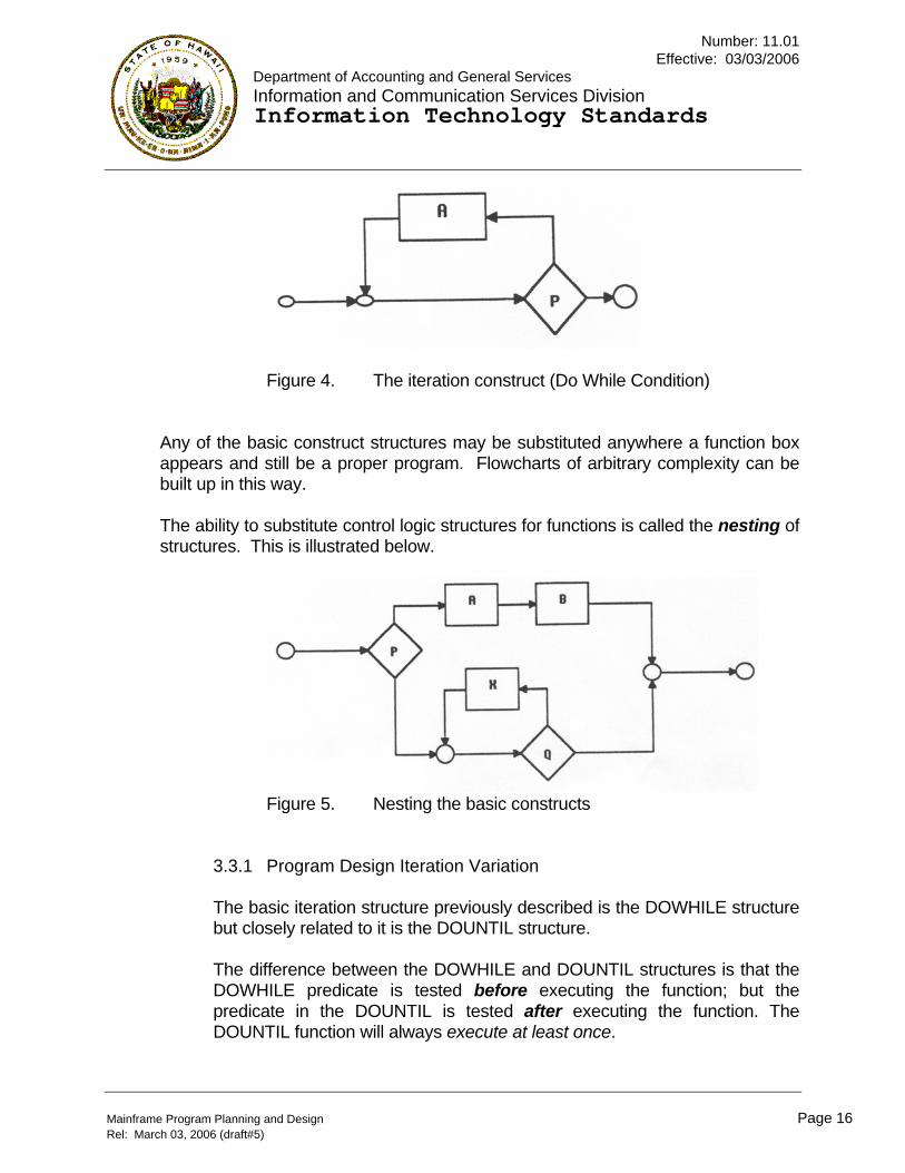
Figure 4. The iteration construct (Do While Condition) Any of the basic construct structures may be substituted anywhere a function box appears and still be a proper program. Flowcharts of arbitrary complexity can be built up in this way. The ability to substitute control logic structures for functions is called the nesting of structures. This is illustrated below.
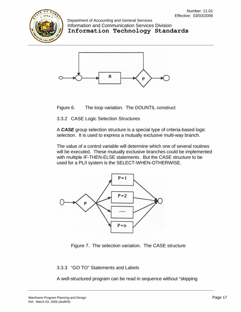
Figure 5. Nesting the basic constructs
3.3.1 Program Design Iteration Variation The basic iteration structure previously described is the DOWHILE structure but closely related to it is the DOUNTIL structure. The difference between the DOWHILE and DOUNTIL structures is that the DOWHILE predicate is tested before executing the function; but the predicate in the DOUNTIL is tested after executing the function. The DOUNTIL function will always execute at least once.
Mainframe Program Planning and Design Page 16 Rel: March 03, 2006 (draft#5)
Number: 11.01 Effective: 03/03/2006
Department of Accounting and General Services Information and Communication Services Division Information Technology Standards
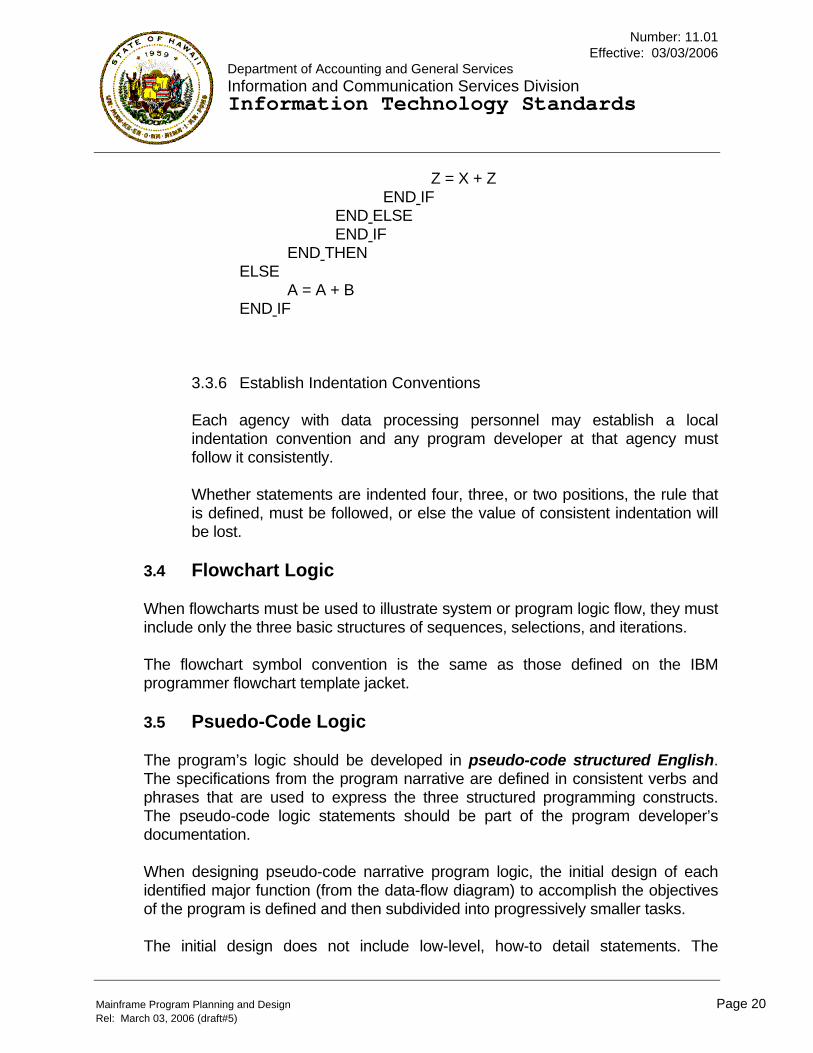
Figure 6. The loop variation. The DOUNTIL construct 3.3.2 CASE Logic Selection Structures A CASE group selection structure is a special type of criteria-based logic selection. It is used to express a mutually exclusive multi-way branch. The value of a control variable will determine which one of several routines will be executed. These mutually exclusive branches could be implemented with multiple IF-THEN-ELSE statements. But the CASE structure to be used for a PL/I system is the SELECT-WHEN-OTHERWISE.
Figure 7. The selection variation. The CASE structure
3.3.3 “GO TO” Statements and Labels A well-structured program can be read in sequence without “skipping
Mainframe Program Planning and Design Page 17 Rel: March 03, 2006 (draft#5)

Number: 11.01 Effective: 03/03/2006
Department of Accounting and General Services Information and Communication Services Division Information Technology Standards
Mainframe Program Planning and Design Page 18 Rel: March 03, 2006 (draft#5)
around.” “GO TO” is not a standard control logic structure. No special effort is required to eliminate “GO TO.” No extra effort is required to “avoid” them. “GO TO” will not occur when the standard control logic structures are used. There are uncommon situations where the use of GO TO may improve readability, such as exception conditions to abort the processing of a function. Do not use varying label variables. Variable label names may result in a segment or procedure’s label name to change. 3.3.4 Program Function Segmentation Easy program readability minimizes the turning of many pages to understand how something works. A program function segment should be kept to a page of code. Programs should be developed in logical features (segments) such as initialization, house-keeping, data manipulation, main-line processes and sub-processes, Input/Output, and summarization. The selected label name for these segments will have numerical prefixes so that the external reference list generated by the compilers to list the label names in a structured sequence would document the logical flow of the segments. This range of prefixes has been standardized for COBOL and can be found in the “COBOL for MVS Standards and Conventions,” IT standards document 11.10. The characteristics of good program segmentation are: a. The program is divided into separate functional pieces that relate to
each other in a functional, top-down hierarchical manner. Segments at the top of the hierarchy should contain high-level control function perform-statements.
b. A well-designed segment carries out only functions and processes
that are closely related to each other.

Number: 11.01 Effective: 03/03/2006
Department of Accounting and General Services Information and Communication Services Division Information Technology Standards
Mainframe Program Planning and Design Page 19 Rel: March 03, 2006 (draft#5)
c. An identified segment communicates with other segments in controlled predictable ways. For example in PL/I systems, each segment consists of logical procedure statements, and the only communication between segments would be through global or local parameter lists.
3.3.5 Program Code Indentation Consistent indentation enhances readability so that the finished program exhibits, in a pictorial way, the relationships among statements indented by a consistent amount of spaces to show the scope of control. In pseudo-code process statements and actual language code, the processing associated with IF-THEN-ELSE will be indented right of the IF-THEN-ELSE clause. The THEN and ELSE word would be alone on a line. The code controlled by a group or a block of codes should be indented to visually isolate the group of statements to be processed within the group or block. Paragraph or label names will be left justified on a line by themselves. Consistent indentation makes it easier to understand, to verify, and to check the logic for correctness. An example of logical nesting of the IF-THEN-ELSE with consistent indentation is shown below:
IF CONDITION P IS TRUE THEN DO B = A + B IF CONDITION Q IS TRUE THEN C = 12 ELSE DO C = 36 IF CONDITION R IS TRUE THEN Y = X + Y ELSE
Number: 11.01 Effective: 03/03/2006
Department of Accounting and General Services Information and Communication Services Division Information Technology Standards
Mainframe Program Planning and Design Page 20 Rel: March 03, 2006 (draft#5)
Z = X + Z END IF END ELSE END IF END THEN ELSE A = A + B END IF
3.3.6 Establish Indentation Conventions Each agency with data processing personnel may establish a local indentation convention and any program developer at that agency must follow it consistently. Whether statements are indented four, three, or two positions, the rule that is defined, must be followed, or else the value of consistent indentation will be lost.
3.4 Flowchart Logic When flowcharts must be used to illustrate system or program logic flow, they must include only the three basic structures of sequences, selections, and iterations. The flowchart symbol convention is the same as those defined on the IBM programmer flowchart template jacket. 3.5 Psuedo-Code Logic The program’s logic should be developed in pseudo-code structured English. The specifications from the program narrative are defined in consistent verbs and phrases that are used to express the three structured programming constructs. The pseudo-code logic statements should be part of the program developer’s documentation. When designing pseudo-code narrative program logic, the initial design of each identified major function (from the data-flow diagram) to accomplish the objectives of the program is defined and then subdivided into progressively smaller tasks. The initial design does not include low-level, how-to detail statements. The
Number: 11.01 Effective: 03/03/2006
Department of Accounting and General Services Information and Communication Services Division Information Technology Standards
Mainframe Program Planning and Design Page 21 Rel: March 03, 2006 (draft#5)
program developer manages complexity by iteratively evolving the problem solution one hierarchical level of detail at a time. The basic idea is to begin with a top-level logic, attach functional processes with a little detail, then fill in the successive levels, refining and expanding the original plans until the design is complete. An example of the evolution of program development from data flow to structure chart, and then to the first level of pseudo-code is shown in the Appendix. The basic control logic structures and indentation in pseudo-code are used in a carefully controlled way. Pseudo-code uses statements similar to programming statements but they are not bound by formal syntactical rules. Pseudo-code is used to spell out detailed design logic. Because of these similarities the translation from pseudo-code functional statements to the programming language statements should be straightforward. Meaningful data, procedure, or label names in the form of an action word plus a qualified object are used to identify the purpose or function of the data or processing procedures and program elements. Program statements implementing control logic structures are indented to show the scope of influence of the structures. 3.6 Efficiency Considerations A “highly efficient” program source code that is very complex and difficult to maintain is not really efficient, in the context of total cost of the application system. Emphasis must be placed on program readability, maintainability, scalability, and effectiveness as well as computer efficiency. 3.7 Fine tune Program Fine tuning a program may become necessary to optimize the use of the computer processing unit (CPU). One way to minimize the job’s execution time would be to identify those portions of the program that are most heavily used, concentrate application development on those few segments, and place these segments close to the start of the mainline processes of the procedure division. Code the one-time, initialization or infrequently “called” procedures to be performed as in-line paragraph called processes.

Number: 11.01 Effective: 03/03/2006
Department of Accounting and General Services Information and Communication Services Division Information Technology Standards
Mainframe Program Planning and Design Page 22 Rel: March 03, 2006 (draft#5)
The short, heavily used loops can be optimized by moving statements that are not directly affected by the loop outside of the repeated iterative loop. Do not use the program language compiler for numeric data conversions. Keep the logical construct specifications of the Input/Output (I/O) verbs down to a bare minimum, ideally, code only one Input and one output statement per data file. If excessive paging in a virtual storage system is a problem, place procedures that are used together close to each other so their load modules should be placed in the same virtual page. 3.8 References In addition to this discussion on Structured Programming, a similar discussion may be found in the SDM/Structured systems development methodology’s SIS (systems internal specifications) manual.
4 PROGRAMMING AND TESTING The State of Hawaii Executive Branch’s established programming language standards and conventions are to be followed during the design and development of program code for any application program. Each agency DP coordinator has a copy of the IT standards for the languages supported at ICSD. By following these standards, the programs within application systems should then be uniform and consistent in organization, structure, style, and content. The project DPSA is responsible for establishing common shared application subroutines for coders to standardize the common processes within the application system. The developed program code should be self-documenting, readable, and easy to modify, maintain, and update by other maintenance programming personnel. The project DPSA is responsible for developing the system test plan and strategy for application program integration for the system. For the continuity and integrity of the application system throughout its lifetime, the
Number: 11.01 Effective: 03/03/2006
Department of Accounting and General Services Information and Communication Services Division Information Technology Standards
Mainframe Program Planning and Design Page 23 Rel: March 03, 2006 (draft#5)
computer programmer should develop a permanent set of data that would test all logic branches in the program. The benchmark data set should reside in a library of test data sets. This data should be reapplied to the program whenever the program is enhanced or modified.
4.1 Programming Languages
The State’s Executive Branch has standardized on COBOL For MVS. Programs may be developed in PL/I, FORTRAN, or Basic Assembler Language only when there is a need for compatibility with existing software or if the application is only suited for these languages. The State supported data base languages are ADABAS and NATURAL on the IBM. On-line IBM-based applications may be created with CICS. The computer programmer may recommend an application programming language, but the project system analyst is responsible for the final determination of the program’s language. All of State supported program languages have a statewide standards document that the agency DP Coordinator has on file. 4.2 Utility Software Utility software are general-purpose programs to perform commonly executed functions. Some utilities available at ICSD include EasyTrieve Plus, IBM/ISPF, FDR (Fast Dump Restore), PANVALET, and CA-SORT. A listing and description of utility software that are available at ICSD may be found in standards document 04.01. 4.3 Programmer Productivity Tools ICSD supports several application development tools. A productivity software product from Computer Associates named CA-Optimizer can be used to improve COBOL-For-MVS program development and testing time. 4.4 Program Testing Program testing procedures initially begins with desk checking of the language code for spelling errors.

Number: 11.01 Effective: 03/03/2006
Department of Accounting and General Services Information and Communication Services Division Information Technology Standards
Mainframe Program Planning and Design Page 24 Rel: March 03, 2006 (draft#5)
The second level of testing is the execution of the program with the language compiler to achieve a syntactically correct program. The third level of testing is to check the logic of the program so that the program does what it was intended to do in the simplest and most efficient manner, and that all logical paths are tested out. The State has software products that are capable of creating test data. The reference manual and supporting documentation to use utilities is available in standards attachments – Vendor Materials. The IBM System Utilities manuals for generating test data can be acquired by the DP Coordinator for each Executive Branch department through their IBM marketing representative. 4.5 Program Documentation Program documentation for production application systems must be standardized to minimize any need for intervention between the person who developed the program and the person who will be maintaining the program. In a central application production library, the program developer should consider supplementing the self-documented program source code with: a. The overall application system flowchart that shows the placement of the
program in the system. b. A copy of the operations production schedule that shows when the program
should be submitted for execution. c. The permanent data set names associated with data to be used in the
program, the sample list of typical records in the data sets, and sample of report listings that should be generated by the program, and the listing of benchmarking test data sets (with their DSNAME’s).
d. A listing of the application defined cataloged procedures used in the
production job stream, that are stored in a JCL member library like “EDPD.PROCLIBA”.
e. A listing of JCL control parameters or control statement members stored in
a parameter library like “EDPD.PARMLIB.”

Number: 11.01 Effective: 03/03/2006
Department of Accounting and General Services Information and Communication Services Division Information Technology Standards
Mainframe Program Planning and Design Page 25 Rel: March 03, 2006 (draft#5)
f. A listing of the sample execution run of the program and sample output
reports. 5 PROGRAM IMPLEMENTATION The implementation of a production program must be preceded by conversion procedures developed by the project system analyst. The conversion procedures should include a phase to train the users of the program and steps to migrate the users operations to implement and use the program.
5.1 Source Program Storage All source code to run on the IBM systems will be stored in PANVALET files. During the testing mode, they will be stored in the data set “EDPD.PANVTEST.” During the production mode, they should be stored in the data set “EDPD.PANVPROD.” The execution procedures can be found in the “PANVALET User’s Guide,” IT standards document 11.04.01. 5.2 Load Module Program Storage
All load modules for test programs on the IBM mainframe systems will be stored on the ICSD system data set “EDPD.LINKLIBT.” All load modules for production programs will be stored on the ICSD system data set “EDPD.LINKLIBP.” 5.3 Convert from Test to Production Before an application system is turned over to ICSD-PSB (production services branch) as a tested and completed assignment, the computer programmer should refer to IT standards document 07.05 Production Job Documentation, to find out the processes, procedures and documentation that must be completed to convert the project from test to production. 5.4 User Documentation The recommended contents of the User’s Documentation may be found in SDM/Structured, Implementation Phase. In most cases, the project group that developed the application is responsible for developing the user’s documentation. 5.5 Operations Documentation
Number: 11.01 Effective: 03/03/2006
Department of Accounting and General Services Information and Communication Services Division Information Technology Standards
Mainframe Program Planning and Design Page 26 Rel: March 03, 2006 (draft#5)
In most cases, the project group that develops the application is responsible for developing the operation’s documentation. The description and contents of the required documents for the “Operation’s Documentation” is found in the “Production Job Documentation,” IT standards document 07.05. 5.6 Schedule Test Job The programmer is usually responsible for scheduling computer resources, time for test jobs, and for coordinating the program’s operational needs with the ICSD-PSB Scheduler. But for very large or special resource requirements, the project manager should coordinate the test job scheduling. 5.7 Production Job Stream Once tested to the satisfaction of the requesting agency, the regular submission of the system’s job control and procedures stream should either be transferred from the applications development staff to the user, or transferred from the applications development staff to the ICSD-PSB. A cataloged job control production stream must be created and placed in the ICSD-PSB library, “EDPD.PROCLIBA”. or in the User Agency’s production procedure library. Before control of any IBM mainframe-based application is transferred from the applications staff, the programmer must transfer all load modules from the test development library, “EDPD.LINKLIBT,” to the production library. This production library is usually “EDPD.LINKLIBP,” but it may be an agency-assigned partitioned data set. The programmer will transfer IBM mainframe based application load modules through TSO using ISPF.
5.7.1 From TEST to PRODUCTION Any application system to be submitted by ICSD PSB Control should have the final program load modules reside in the applications production library designated by the ICSD Systems Services Branch. This is usually “EDPD.LINKLIBP.” The computer programmer is responsible for the final MOVE or temporary COPY of the application program load modules from the test library “EDPD.LINKLIBT” to the production library “EDPD.LINKLIBP”. 5.7.2 Release EDPD.LINKLIBT Space

Number: 11.01 Effective: 03/03/2006
Department of Accounting and General Services Information and Communication Services Division Information Technology Standards
Mainframe Program Planning and Design Page 27 Rel: March 03, 2006 (draft#5)
The physical transfer (move) of the application load modules from the test library to the production library occurs immediately when the ICSD PSB control clerk submits and executes the transfer job. But the physical delete (removal) of the application load modules from the test library “EDPD.LINKLIBT” is actually done only once a day, when the computer operating system is backed-up. The operating system DASD back-up jobs are usually executed by ICSD PSB very early on the morning after the transfer job was submitted.

Number: 11.01 Effective: 03/03/2006
Department of Accounting and General Services Information and Communication Services Division Information Technology Standards
Mainframe Program Planning and Design Page 28 Rel: March 03, 2006 (draft#5)
APPENDIX

Number: 11.01 Effective: 03/03/2006
Department of Accounting and General Services Information and Communication Services Division Information Technology Standards
Structured Program Development
This example illustrates the transitions from a data flow diagram to a hierarchical structured chart and to the initial pseudo-code of the program logic. This pseudo-code is the foundation for the program to be developed. The details for the program comes from expanding the application specifications into detailed procedural steps. A definition for the special characters on the data flow diagram are: (+) Identifies mutually exclusive processes. (*) Identifies multiple paths that must be processed.
Hypothetical Data Flow Diagram
Mainframe Program Planning and Design Page 29 Rel: March 03, 2006 (draft#5)

Number: 11.01 Effective: 03/03/2006
Department of Accounting and General Services Information and Communication Services Division Information Technology Standards
Hypothetical Program Hierarchical Structure Chart
Mainframe Program Planning and Design Page 30 Rel: March 03, 2006 (draft#5)

Number: 11.01 Effective: 03/03/2006
Department of Accounting and General Services Information and Communication Services Division Information Technology Standards
Convert Data-Flow-Diagram To Pseudo-Code The first level of pseudo-code logic is developed by reading the functional modules on the previous hierarchical structure chart from left to right and top to bottom. The functional modules had been identified from the data flow diagram. The next level of the pseudo-code evolution is the systematic expansion of these functional modules with general processing steps identified from the application specifications or with dummy modules if the processes are still being defined. The final version of pseudo-code is converted to a programming language and testing is done after each increment of the functional module expansions is developed. Pseudo-Code created from Program Hierarchical Structure Chart developed by iteratively evolving and expanding the processing logic. Pseudo-code logic development is an iterative process with more detailed processing statements specified at the next level
Mainframe Program Planning and Design Page 31 Rel: March 03, 2006 (draft#5)

Number: 11.01 Effective: 03/03/2006
Department of Accounting and General Services Information and Communication Services Division Information Technology Standards
Mainframe Program Planning and Design Page 32 Rel: March 03, 2006 (draft#5)
of the pseudo-code.
ASSUME THERE-ARE-SOME-RECORDS AND GET-THE-FIRST-RECORD RUN 200-PROCESS-A-RECORD ROUTINE WHILE THERE-ARE-MORE-RECORDS START THE 200-PROCESS-A-RECORD ROUTINE WHEN THERE-ARE-NO-MORE-RECORDS THEN STOP-THE-JOB OR ELSE, DO THE FOLLOWING: RUN 600-MANIPULATE-THE-DATA RUN 700-PUT-OUT-A-RECORD RUN 500-GET-GOOD-DATA ROUTINE END THE 200-PROCESS-A-REC0RD ROUTINE START THE 500-GET-GOOD-DATA ROUTINE RUN 900-READ-A-RECORD ROUTINE RUN 510-EDIT-DATA-ELEMENTS ROUTINE WHEN BAD-DATA-FOUND THEN RUN 930-DISPLAY-BAD-DATA ROUTINE OR ELSE, DO THE FOLLOWING: END THE 500-GET-GOOD-DATA ROUTINE START THE 700-PUT-OUT-A-RECORD ROUTINE RUN 710-BUILD-NEW-RECORD RUN 940-WRITE-A-NEW-RECORD RUN 950-DISPLAY-IMAGE-OF-NEW-DATA END THE 700-PUT-OUT-A-RECORD ROUTINE