mail to: visit our web site: ship to:
TRANSCRIPT

1© Copyright 2006 Zoeller Co. All rights reserved.
Model Number: ______________ Date Code: _______________
Simplex Duplex
Packaged System Field Assembled System
Job Name: ____________________________________________
Distributor: ____________________________________________
Date of Purchase: _________ Zoeller S/O No.: ______________
Contractor: ____________________________________________
Date of Installation: ____________________________________
System Readings During Start-up: Voltage _____ Amps _____
OWNER’S MANUALMODELS 840 & 841 SUBMERSIBLE GRINDER UNITS
aid in the own er ship of a Zoeller submersible wastewater prod uct. Please read and re view this manual before install-ing the prod uct. Follow the steps in this manual for a proper start-up. Many items con tained with in, when fol lowed cor rect ly, will not only ensure a long and prob lem-free life for the pump, but also save time and money during installation. Ref er ence FM1308 for re place ment parts on 840 Series Grind er Pumps or FM2180 for model 841 parts. Should fur ther as sis tance be necessary please call our Tech ni cal Ser vice De part ment at 1-800-928-PUMP (7867).
Owner’s Information
Safety InstructionsTO AVOID SERIOUS OR FATAL PERSONAL INJURY OR MA- JOR PROPERTY DAMAGE, READ AND FOLLOW ALL SAFETY INSTRUCTIONS IN THIS MANUAL AND ON THE PUMP.
THIS MANUAL IS INTENDED TO ASSIST IN THE IN STAL LA TION AND OPERATION OF THIS UNIT AND MUST BE KEPT WITH THE PUMP.
This is a SAFETY ALERT SYMBOL.When you see this symbol on the pump or in the man u al, look for one of the following signal words and be alert to the potential for personal injury or property damage.Warns of hazards that WILL cause serious personal injury, death or major property damage.Warns of hazards that CAN cause serious personal injury, death or major property damage.Warns of hazards that CAN cause personal injury or prop er ty damage.INDICATES SPECIAL INSTRUCTIONS WHICH ARE VERY IMPORTANT AND MUST BE FOLLOWED.
THOROUGHLY REVIEW ALL INSTRUCTIONS AND WARNINGS PRIOR TO PERFORMING ANY WORK ON THIS PUMP.
MAINTAIN ALL SAFETY DECALS.
PUMPS WITH THE “UL” MARK AND PUMPS WITH THE “US” MARK ARE TESTED TO UL STANDARD UL778. CSA CERTIFIED PUMPS ARE CERTIFIED TO CSA STANDARD C22.2 NO. 108.
Table of ContentsSafety Instructions ....................................................................... 1Limited Warranty and Application .............................................. 2Preinstallation Checklist .............................................................. 3General Information ..................................................................... 4Pump Wiring Instructions ............................................................ 5Typical Indoor Prepackaged System .......................................... 6Indoor Prepackaged Installation Instructions ........................... 7Typical Outdoor Prepackaged System ....................................... 8Outdoor Prepackaged Installation Instructions ........................ 9Operation ..................................................................................... 10Cutter Maintenance .................................................................... 11Service Checklist ........................................................................ 12
REFER TO WARRANTY ON PAGE 2.
SECTION: 6.10.021 FM2168
0906Supersedes
0206
NOTICE TO INSTALLER: Instructions must remain with installation.
Product information presented here re fl ects con di tions at time of publication. Consult factory re gard ing dis crep an cies or in con sis ten cies. MAIL TO: P.O. BOX 16347 • Louisville, KY 40256-0347
SHIP TO: 3649 Cane Run Road • Louisville, KY 40211-1961(502) 778-2731 • 1 (800) 928-PUMP • FAX (502) 774-3624
Congratulations on the purchase of a Zoeller submers-ible grinder pump. For over sixty years the name Zoeller has rep re sent ed the standard for sub mers ible de w a ter ing and sew age pumps. The same high quality work man ship and easy main te nance design has been in cor po rat ed into this line of heavy-duty sub mers ible grinder pumps. This Zoeller pump will pro vide years of trou ble-free service when installed ac cord ing to the manufacturer’s recommendations. This manual in cor po rates the in stal la tion, operation,maintenance, and service instructions into one doc u ment to
visit our web site:www.zoeller.com

2© Copyright 2006 Zoeller Co. All rights reserved.
LIMITED WARRANTY
APPLICATIONS1. Zoeller Grinder Pumps are designed for grind ing and
pumping sanitary sewage from sub mers ible lift stations. The pump is in tend ed to grind and pump reasonable quan ti ties of items normally found in sanitary sewage applications.
2. Zoeller 840 and 841 Grinder Pumps can be installed in new applications or as a direct replacement for any grinder application of like size and capacity. Some rail system retrofi t kits are available.
3. The 840 and 841 can be installed in a Prepackaged Job Ready System or may be used in a Field Assembled basin package. Pages 6 and 8 show a couple of Pre- pack aged Systems. Field Assembled Systems are dis cussed on pages 3 and 4.
4. Zoeller 840 and 841 Grinder Pumps can be retrofi tted to ex ist ing positive displacement pump installations.
wash towels or feminine sanitary products, etc. in all ap-plications other than in raw sewage pumping applications. The warranty set out in the paragraph above is in lieu of all other warranties expressed or implied; and we do not authorize any representative or other person to assume for us any other liability in connection with our products.
Contact Manufacturer at, 3649 Cane Run Road, Lou is ville, Ken tucky 40211, Attention: Cus tom er Ser vice De part ment to obtain any need ed repair or re place ment of part(s) or additional in for ma tion pertaining to our warranty.
MANUFACTURER EXPRESSLY DIS CLAIMS LI A BIL I TY FOR SPE CIAL, CON SE QUEN TIAL OR IN CI DEN TAL DAM AG ES OR BREACH OF EX PRESSED OR IMPLIED WARRANTY; AND ANY IMPLIED WAR RAN TY OF FIT- NESS FOR A PAR TIC U LAR PUR POSE AND OF MER- CHANT ABIL I TY SHALL BE LIM IT ED TO THE DU RA TION OF THE EX PRESSED WAR RAN TY.
Some states do not allow limitations on the duration of an implied warranty, so the above limitation may not apply to you. Some states do not allow the exclusion or limitation of incidental or con se quen tial dam ag es, so the above lim i -ta tion or exclusion may not apply to you.
This warranty gives you specifi c legal rights and you may also have other rights which vary from state to state.
Recommended Limits of Application 800 Series Grinder PumpsThese recommended application limits are for pump stations pumping to a gravity main. Low-pressure pipe systems should be designed with a pump located at each house. For applications where a lift station would handle between 15 and 60 homes, consider the 71 Series grinder pump, which is available through Zoeller Engineered Products. For applications where a lift station would handle more than 60 homes, a solids handling type pump should be considered.
*Zoeller Company does not recommend a simplex station on anything over two homes in order to maintain continuous service during unusual conditions.
Simplex Station Duplex StationModel HP Homes GPD Homes GPD
820 2 1 400 2 800840 w/o Reversing Control 2 2* 800 10 4,000840 w/ Reversing Control 2 2* 800 15 6,000841 3 2* 800 10 4,000
Manufacturer warrants, to the purchaser and subsequent owner during the warranty period, every new product to be free from defects in material and workmanship under normal use and service, when properly used and maintained, for a period of one year from date of purchase by the end user, or 18 months from date of original manufacture of the product, whichever comes fi rst. Parts that fail within the warranty period, one year from date of purchase by the end user, or 18 months from the date of original manufacture of the product, whichever comes fi rst, that inspections determine to be defective in material or workmanship, will be repaired, replaced or remanufactured at Manufacturer's option, pro-vided however, that by so doing we will not be obligated to replace an entire assembly, the entire mechanism or the complete unit. No allowance will be made for shipping charges, damages, labor or other charges that may occur due to product failure, repair or replacement.
This warranty does not apply to and there shall be no warranty for any material or product that has been disas-sembled without prior approval of Manufacturer, subjected to misuse, misapplication, neglect, alteration, accident or act of God; that has not been installed, operated or maintained in accordance with Manufacturer's installation instructions; that has been exposed to outside substances including but not limited to the following: sand, gravel, cement, mud, tar, hydrocarbons, hydrocarbon derivatives (oil, gasoline, solvents, etc.), or other abrasive or corrosive substances,

3© Copyright 2006 Zoeller Co. All rights reserved.
Preinstallation Checklist1. Inspect your grinder pump. If the unit has been damaged in
shipment, contact your dealer before installing. Do Not remove the test plug in the cover nor the motor housing.
2. Carefully read all literature to familiarize yourself with details re gard ing in stal la tion and use. Retain materials for future refer-ence.
1. Make sure pump connection con tains a ground ter mi nal. The power cord on all Zoeller Grind er Pumps con tains a green con duc tor for grounding to help protect you against the pos si bil i ty of electric shock.
2. Make certain the electrical service is within reach of the power supply cord.
3. Make sure any panels and branch circuits are equipped with proper size fuses and circuit break ers. An in de pen dent pow er circuit is rec om mend ed, sized ac cord ing to the National Elec tri cal Code, for the current shown on the grinder pump name plate.
4. For your protection, always dis con nect the pow er source to the grinder pump before han dling. All grinder pumps must be prop er ly ground ed and wired in ac cor dance with the “Na tion al Elec tri cal Codes” and all local codes and ordinances.
5. Installation of electrical hardware and checking of control pan els and circuits should be performed by a qualifi ed li censed electrician.
6. Risk of electrical shock - These pumps have not been in ves ti gat ed for use in swimming pool areas.
7. According to the state of California (Prop 65), this product contains chemicals known to the state of California to cause can cer and birth defects or other reproductive harm.
1. Make sure the power source is capable of handling the electrical re quire ments of the grinder pump, as indicated on the nameplate.
2. A dis con nect switch should be installed ahead of the pump.
3. The Grinder pumps are operated by control panels with vari-able level fl oat control switches. It is the re spon si bil i ty of the in stall ing party to see that fl oat control switches will not hang up on the grinder pump or other pit peculiarities and are secured so that the grinder pump will shut off. It is rec om mend ed to use rigid pipe and fi ttings and the pit be 24" in diameter for simplex sys tems and 36" in di am e ter for duplex systems or larger.
4. Grinder installations should be checked yearly for debris and/or build up which may interfere with the “ON” or “OFF” positions of variable lev el fl oat control switches. Repair and service, other than cutter as sem bly main te nance, should be per formed by Zoeller authorized service stations only.
5. Maximum operating tem per a ture must not ex ceed 130°F,(54°C).
6. Pump and fl oat switch electrical connections must be properly installed and protected from submergence.
7. Junction box conduit must be installed with watertight connection.Do not attempt to turn star cutter lo cat ed
on bottom of the unit with fi ngers. Use a wrench when check ing or re mov ing star cutter.
SEE BELOW FOR LIST OF WARNINGS SEE BELOW FOR LIST OF CAUTIONS
Electrical Data
AmpsKVACode
WindingResistanceLine-to-LineModel BHP RPM Voltage Phase Hertz Full Load In Air Shut Off Locked
RotorI840 2 3450 200 1 60 20.0 6.6 12.1 60 H 1.0 / 1.5E840 2 3450 230 1 60 17.2 4.0 10.9 56 F 1.3 / 4.0J840 2 3450 200 3 60 12.3 3.7 7.7 54 L 1.9F840 2 3450 230 3 60 10.8 3.3 6.9 42 K 2.4G840 2 3450 460 3 60 5.5 1.6 3.5 21 K 9.7
BA840 2 3450 575 3 60 4.5 1.0 2.5 11 F 15.3I841 3 3450 200 1 60 20.0 6.6 12.1 60 H 1.0 / 1.5E841 3 3450 230 1 60 17.2 4.0 10.9 56 F 1.3 / 4.0J841 3 3450 200 3 60 12.3 3.7 7.7 54 L 1.9F841 3 3450 230 3 60 10.8 3.3 6.9 42 K 2.4G841 3 3450 460 3 60 5.5 1.6 3.5 21 K 9.7
BA841 3 3450 575 3 60 4.5 1.0 2.5 11 F 15.3
4© Copyright 2006 Zoeller Co. All rights reserved.
General Information
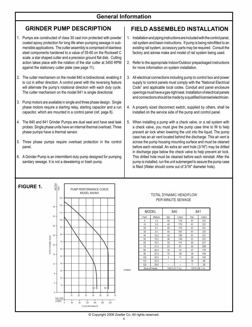
GRINDER PUMP DESCRIPTION1. Pumps are constructed of class 30 cast iron protected with pow der
coat ed epoxy protection for long life when pump ing sewage in sub-mersible ap pli ca tions. The cut ter as sem bly is comprised of stain less steel com po nents hard ened to a value of 55-60 on the Rockwell C scale; a star shaped cutter and a pre ci sion ground fl at disk. Cutting action takes place with the rotation of the star cutter at 3450 RPM against the stationary cutter plate (see page 11).
2. The cutter mechanism on the model 840 is bidirectional, enabling it to cut in either direction. A control panel with the reversing feature will alternate the pump’s ro ta tion al di rec tion with each duty cycle. The cutter mechanism on the model 841 is single directional.
3. Pump motors are available in single and three phase design. Single phase motors require a starting relay, starting capacitor and a run capacitor, which are mounted in a control panel (ref. page 8).
4. The 840 and 841 Grinder Pumps are dual seal and have seal leak probes. Single phase units have an internal thermal overload. Three phase pumps have a thermal sensor.
5. Three phase pumps require overload protection in the control panel.
6. A Grinder Pump is an intermittent duty pump designed for pumping sanitary sewage. It is not a dewatering or trash pump.
FIELD ASSEMBLED INSTALLATION1. Installation and piping instructions are in clud ed with the control panel,
rail system and basin in struc tions. If pump is being retrofi tted to an ex ist ing rail system, accessory parts may be re quired. Consult the factory and advise make and model of rail system being used.
2. Refer to the appropriate Indoor/Outdoor pre pack aged instructions for more information on system in stal la tion.
3. All electrical connections including pump to con trol box and power supply to control pan els must comply with the “National Electrical Code” and applicable local codes. Conduit and panel enclosure openings must have a gas-tight seal. Installation of elec tri cal panels and con nec tions should be made by a qual i fi ed licensed electrician.
4. A properly sized disconnect switch, supplied by others, shall be installed on the service side of the pump and control panel.
5. When installing a pump with a check valve, or a rail system with a check valve, you must give the pump case time to fi ll to help prevent air lock when lowering the unit into the liquid. The pump case has an air vent located behind the discharge. This air vent is across the pump housing mount ing surface and must be cleaned before each re in stall. An extra air vent hole (3/16") may be drilled in dis charge pipe below the check valve to help prevent air lock. This drilled hole must be cleaned before each re in stall. After the pump is installed, run the unit submerged to assure the pump case is fi lled (Water should come out of 3/16" di am e ter hole).
FIGURE 1.
016532
PUMP PERFORMANCE CURVE
MODEL 840/841
0 40 80 120 160 200 240
70605040302010
0
104
8
12
16
20
130
70
60
50
40
30
20
FLOW PER MINUTE
GALLONS
LITERS
TO
TAL
DY
NA
MIC
HE
AD
80
9028
24
ME
TE
RS
FE
ET
100
110
120
32
36
840 841
TOTAL DYNAMIC HEAD/FLOW
PER MINUTE SEWAGE
MODEL
Feet
Shut-off Head:
840
Meters Gal. Liters
5
10
20
30 9.1
6.1
3.0
1.5
44
45
167
170
104 ft (31.7 m)
60
50
40
90
80
70
110
100
120
12.2
15.2
18.3
21.3
24.4
27.4
30.5
33.5
36.6
42
36
30 114
136
159
23
16
10 38
61
87
3
--
-- --
--
11
125 ft (38.1 m)
14438
18
7
28 106
68
26
61
55
47
60
61
61
61
231
208
178
227
231
231
231
841
Gal.
61
61
231
231
Liters
45 170
45 170

5© Copyright 2006 Zoeller Co. All rights reserved.
MOISTURE SENSOR
L1 L2 L3
POWER CABLE
CONTACTORT1 T2 T3
208V/230/460V
3ø POWER
SENSOR CABLE
THERMAL SENSOR
OR
AN
GE
BLA
CK
RE
D
WH
ITE
GR
EE
N
(18-4 OR 18-5)
BEFORE 6/2000NORMALLY OPEN
330K OHMS RESISTANCE
NORMALLY CLOSED
Pump Wiring Instructions
FOR YOUR PROTECTION, ALWAYS DISCONNECT THE PUMP FROM ITS POWER SOURCE BEFORE HANDLING. All electrical connections must be wired and grounded in accordance with the National Electrical Code and all applicable
local codes and or di nanc es. “Risk of electrical shock” Do not remove the power supply cord and strain relief or connect conduit directly to pump.
Installation and checking of electrical circuits and hardware should be performed by a qualifi ed licensed electrician.
FIGURE 2.LEAD IDENTIFICATION WIRING DIAGRAM
SINGLE PHASE-2HPMODEL 840
SK1367 009048
THREE PHASEMODELS 840 & 841
FIGURE 4.
FIGURE 3.
L1START RELAY
START CAPACITOR
GREE
N
RED
WHI
TE
BLAC
K
BLUE
ORAN
GE
MOISTURESENSORTERMINALS
WHI
TE
BLAC
K
14-618-2
REVERSE MOTOR ROTATION BY INTERCHANGINGORANGE WIRE WITH RED WIRE.
L2
RUN CAPACITOR
GROUND SCREW
2
1
5
2
1
5
PUMP
START RELAY
START CAPACITORRUN CAPACITOR
RED
WHITE
ORANGE
BLACK
MAIN START
PROTECTOR
BLAC
K
WHI
TE
L1 L2
T2T1
230V ACOR
208V AC
CONTACTOR
BLUE
SINGLE PHASEMODEL 841LEAD IDENTIFICATION WIRING DIAGRAM
WIRING DIAGRAMLEAD IDENTIFICATION
14-4
18-4
L1 L2 L3
T1 T2 T3
BLA
CK
RE
D
GR
EE
N
POWERCORD
MAGNETICSTARTER
CORDSENSOR
WH
ITE
BLACKORANGE
RE
D
WH
ITE
MOISTURESENSOR
TERMINALS
SENSORTERMINALS
TEMPERATURE
OR
18-5
GR
EE
N
START RELAY
START CAPACITOR
MOISTURESENSORTERMINALS
BLAC
K
WHI
TE
L1 L2
RUN CAPACITOR
GROUND SCREW
BLAC
K
WHI
TE
RED
GREE
N
18-2 14-4
2
1
5
SK1368 SK1370
SK2399
RUN CAPACITOR START CAPACITOR
T1
BLAC
K
WHI
TE
T2
START RELAY
L1 L2
208V ACOR
230V AC
CONTACTOR
YELL
OW
MAIN WINDING
AUXILIARY WINDING
OVERLOAD
BLUE
5
5
ORAN
GE
WHI
TE
RED
BLAC
K
43
43
21
21
GREE
N
WHI
TE
BLAC
K
RED
MOTORCHAMBER
COVERCHAMBER
2
1
5
SK2400

6© Copyright 2006 Zoeller Co. All rights reserved.
All installations must comply with all applicable electrical and plumbing codes, including but not limited to the Na tion al Electrical Code, local, regional and/or state plumbing codes, etc.
Indoor Prepackaged SystemFIGURE 5.
VARIABLE LEVEL FLOAT SWITCHES
MOISTURE SENSOR CORD
3" GROMMET SEAL
10" X 1/4" STEEL
16" X 1/4" STEEL
5/16" 304 STAINLESS STEEL
24" X 1/4" STEEL
TO CONTROL PANEL
CORD SEAL
INSPECTION PLATE
BASIN COVER
PUMP PLATE
LIFTING U-BOLT
PUMP POWER CORD
(VENT CONNECTION)
24" NOMINAL
OFF
ONALARM
36"
TO CONTROL PANEL 1 1/4" PVC SLIP X SLIPBALL VALVE
1 1/4" FEMALE NPTCAST IRON CHECK VALVE
1 1/4" X 32"GALVANIZED PIPE
1 1/2" X 8"GALVANIZED PIPE
1 1/4" GROMMET SEAL
4" FIBERGLASS HUB
CAST IRON ADAPTERS
(FIELD INSTALLED)
(FIELD INSTALLED)
230V, 1PHGRINDER PUMP
(FIELD INSTALLED)
CONTROL PANEL(FIELD INSTALLED)
W/RUBBER INSERT
SK1695A
SK1695B

7© Copyright 2006 Zoeller Co. All rights reserved.
Indoor Prepackaged System Installation Instructions
This set of instructions is for factory pre pack aged indoor systems only. If your sys tem is a fi eld as sem bled indoor system, use these in struc tions as a guideline. If your system is an out door system then go to the next section in this manual that covers outdoor systems.
1. Indoor grinder pump systems are for installing at grade in an indoor application only. If you will be in stall ing this system outside next to the res i dence then you will need an outdoor sys tem. DO NOT INSTALL THE INDOOR SYSTEM OUTDOORS.
2. Review the drawing in Fig. 5 on page 6 and the actual sys tem to be come familiar with the com po -nents in the grind er pump sys tem. Review where the unit will be in stalled. Determine where the pow er feed, inlet pipe, discharge pipe and vent will be located.
3. Remove the unit from the packing. Indoor pre- pack aged systems are preassembled at the Zoeller Com pa ny and require a minimum of fi eld as sem bly work. All work inside the basin can be per formed via the inspection port. There should be no reason to re move the cover from the basin. Pump and fl oat switch es are already set inside the basin.
4. Remove the inspection plate from the cover. All fl oats are set and tethered for proper op er a tion from the factory. Verify that where the fl oat switch es are set will work for your application. Verifying that the fl oat switches are set prop er ly and will not hang up inside the ba sin is the re spon si bil i ty of the in stall ing con trac tor. Float switches are tied in place for ship ping purposes. Cut the cable tie around each fl oat switch bulb or the unit will not op er ate prop er ly.
5. Dig a hole for the basin. The basin should be lo cat ed in a very low traffi c area within 15' of the pow er dis con nect. The hole should be at least 8" larg er in di am e ter than the basin in order to leave 4" of backfi ll all the way around the pe rim e ter. A min i mum of 4" of compacted subbase is also re quired. Backfi ll and sub base should be 1/8" to3/4" pea gravel or 1/8" to 1/2" crushed stone. Also ref er ence the basin installation in struc tions in clud ed with the unit.
6. The 4" inlet hub should be located between the top lip of the basin and the alarm fl oat “on” level with a min i mum distance of 10 inches between the fl oor of the basin and hub. Determine the location of the inlet hub based upon your inlet pipe ar range ment. The inlet hub must be used with 4" pipe. It is best to in stall the inlet on the side of the basin opposite the fl oat switch es. To install, use a 4" hole saw to drill into the side of the basin at the cor rect elevation. Center the hub inner di am e ter with the hole in the basin. Attach the hub to the side of the basin using the sealant and hard ware pro vid ed.
7. Set the basin in the hole and connect the 4" in let pipe. Caulk or gasket the inlet hub to pipe. Back-fi ll around the ba sin with spec i fi ed me dia. Care should be taken not to damage com po nents or leave voids when back fi ll ing. Fin ish grade of fl oor should be poured in place around the top 6" of the basin as sem bly.
8. Connect the discharge pipe, valves and vent ac- cord ing to all applicable National, State and Lo cal plumb ing codes.
9. Mount the control panel on the wall within 15' of the sys tem. Connect the fl oat switch and pump cords.
10. Clean any debris out of the basin. Fill the basin with water and check the system for proper op er a tion.
11. Record system start-up data for future reference.
12. Seal and secure the inspection plate to the lid us ing the proper bolts and sealant. Pouring con crete around the system can now be com plet ed.

8© Copyright 2006 Zoeller Co. All rights reserved.
Typical Outdoor Grinder Pumping System Installation
All installations must comply with all applicable electrical and plumbing codes, including but not limited to the Na tion al Electrical Code, local, regional and/or state plumbing codes, etc.
FIGURE 6.
24" MIN.
WATERTIGHT
HIGH LEVEL
1 1/4" FEMALE NPT
1 1/4" GALVANIZEDDISCHARGE PIPE
FIBERGLASS
4" RUBBER INLET PIPE SEAL
FIBERGLASS
1 1/4" NPT BRASSDISCONNECT FITTING
1 1/2" SQ. GUIDE RAIL304 STAINLESS STEEL 16 GA.
PUMP CONTROL"ON" FLOAT
"OFF" FLOATPUMP CONTROL
3/8" X 1' 416 STAINLESS
1/8" 302 STAINLESSNEMA 4X J-BOX
ANTI-FLOTATION FLANGE
ALARM FLOAT
SOLID
STAINLESS STEEL FLOAT HOOK
STEEL LIFTING CABLE
STEEL PULL ROD
1 1/4" PVC SCH 40PIPE AND FITTINGS
1 1/4" PVC SLIP X SLIPBALL VALVE
1 1/4"DISCHARGE FITTING
CAST IRON CHECK VALVE
COVER
(FIELD INSTALLED)
60"*
OTHER BASIN SIZES ARE READILY AVAILABLE.
*
(FIELD INSTALLED)CONTROL PANEL
FIBERGLASS BASIN
18" MIN. OR PER STATEAND LOCAL CODES
TO CONTROL PANEL
SK1665

9© Copyright 2006 Zoeller Co. All rights reserved.
Outdoor Prepackaged System Installation Instructions
1. Review the drawing in Fig. 6 on page 8 and the actual sys tem to be come fa mil iar with the components in the pack- aged grind er pump sys tem. Re view where the unit will be in stalled. Determine where the power feed, inlet pipe, and discharge pipe will be located.
2. Remove the unit from packing. Prepackaged outdoor sys tems are preassembled at the Zoeller Company and re quire a min i mum of fi eld assembly work. Float switches are set and teth ered for proper operation from the Fac to ry. The alarm switch should be lo cat ed 2" above the pump “on” level. Three fl oat sys tems used with a control panel are placed at 27", 24", and 15" from the bot tom of the ba sin. Four fl oat sys tems used with a control panel are placed at 30", 27", 24", and 15" from the bottom of the basin. If the invert location is at or below the level of the fl oat switches, contact the factory.
3. Float switches are tied in place for shipping purposes on all model prepackaged systems. Cut the cable tie around each fl oat switch bulb or the unit will not operate properly. Ver i fy that where the fl oat switches are set will work for your ap pli ca tion. Verifying that the fl oat switches are set prop er ly and will not hang up inside the basin is the re spon si bil i ty of the installing contractor.
4. Dig a hole for the basin. The hole should be at least 24" larger in diameter than the basin diameter to provide 12" of backfi ll all around and deep enough to provide either 12" of com pact ed backfi ll or 6" when a concrete pad is required. En sure the removable cover extends above the fi nished grade line and the grade slopes away from the unit. Backfi ll and subbase should be 1/8"–3/4" pea gravel or 1/8"–1/2" crushed stone. (Ref er ence basin installation in struc tions included with unit)
5. Note: Care must be taken when excavating in order to avoid underground utilities and disturbance of ex ist ing struc ture foun da tions. The hole should be located at least ten feet from adjacent structures. Ad- di tion al dis tance may be required to suffi ciently locate the basin outside of the load ing area of the adjacent structures.
6. The location of the inlet hub is determined by the depth of the inlet pipe. The inlet hub must be used with 4" pipe. It is best to in stall the inlet on the side of the basin op po site the fl oat switch es. To install, use a 4" hole saw to drill into the side of the basin at the cor rect el e va tion. Center the hub inner di am e ter with the hole in the basin. Attach the
hub to the side of the basin using the sealant and hard ware pro vid ed.
7. The bottom of the ex ca va tion can now be back fi lled and
com pact ed. Set basin in hole and connect the 4" inlet pipe to the inlet hub.
8. The discharge piping is connected to the 1¼" threaded fi tting located in the basin sidewall.
9. On basin depths of 72" and greater, the system’s disconnect assembly is shipped loose and must be screwed into the discharge piping. Apply pipe dope to threaded connection.
10. Connect pull rod to Pump assembly. Connect lift cable to top of pump. Lower the pump into basin ensuring the dis charge pipe brack et slides into the dis con nect fi tting.
11. Pouring a concrete anchor around system can now be com plet ed. Basin should be fi lled with water when pour-ing concrete to min i mize movement of the system. Back fi ll around basin with spec i fi ed media. Care should be used to avoid damaging com po nents or leaving voids when back fi lling. Refer to Basin installation ref er ence guide on more specifi c requirements.
12. Note: The grinder basin is a sewage holding tank. Vent connection should be installed in accordance with all national, state and local plumbing codes.
13. Dig a trench for the electrical conduit. Trench should be lo cat ed at least 18" deep and follow all applicable NEC codes. Con nect elec tri cal wiring to Junction box ac cord ing to wiring in struc tions included in this man u al and wiring diagram in box. Use the included sealant when clos ing Junction box.
14. Mount the control panel within sight of the system. Connect fl oat switches and pump cords according to the “Pump Wir ing In struc tions” found later in this manual and located inside the panel enclosure.
15. Remove any debris from the basin. Using clean water, check the system for proper operation.
16. Seal and secure the lid using the proper bolts and sealant when using a lid without a formed gasket.
17. Test system for leaks and proper pump operation.
18. Record system start up data for future reference.
This set of instructions is for factory prepackaged outdoor grinder systems only. If this is a fi eld as sem bled outdoor sys tem you can use these in struc tions as a guideline. If this is an indoor system then go to the pre vi ous section in this manual that cov ers indoor systems.

10© Copyright 2006 Zoeller Co. All rights reserved.
Operation
GENERALZoeller pumps are lubricated and tested at the factory prior to shipment and require minimum pre-start-up maintenance.
Maximum operating temperature of pump liquid for grinder pumps must not exceed 130°F (54°C).
These units are not designed to handle liquids other than sanitary sewage. If pump is used to dewater areas with contaminated liquids with heavy or abrasive ma te ri als, the warranty will be void ed.
NAMEPLATE DATAThe nameplate, located on the side of the pump, indicates spe cifi c in for ma tion about the construction of the pump. The model num ber and date code information should be recorded on the front page in the “Owner’s Information” section of this manual.
SHORT TERM STORAGEWhen not in use, the pump should be stored and the following is ad vised:
• Store pump inside whenever possible or cover with some type of protective cov er ing.
• Tape or seal in plastic bag the terminal ends of wire leads.• Spray coat unpainted surfaces with rust inhibiting oil.• The impeller should be rotated every six months in order to
keep the seals lubricated and not develop a permanent set.
If panel is to be stored, the following is advised:
• Store the panel inside whenever possible and leave in the ship ping box.
• All openings shall be sealed.• Store in an upright position.• Do not stack anything on top of panel.
START-UP PROCEDUREBefore placing the equipment into operation the following should be checked:
• Clean pit.• Pump, fl oat switches and electrical cables are dry and properly
installed.• Electrical boxes dry and securely installed.• Floats positioned properly.• Discharge valves open.• 3/16" vent hole drilled in pipe between check valve and
pump.
Once the above has been verifi ed proceed with the following checks:
• Pump power cables and control fl oats properly installed and voltage verifi ed.
• Conduit connections to panel are properly sealed.• After installing the pump into the containment area, with ad e -
quate sub mer gence, open the discharge valve fully. Start the unit using manual controls. If fl ow is appreciably less than rated performance, pump may be air locked. To expel trapped air, jog the unit several times, using the manual controls.
• Have a qualifi ed electrician take voltage and current mea- sure ments with the pump running. Record these readings in the space provided in the “Own er’s In for ma tion” section on page 1 of this manual for future reference.
ADJUSTMENT PROCEDUREPumps: No adjustments are required.Floats: Refer to the system drawing or to the panel wiring
sche mat ic for the desired lo ca tion of each fl oat switch setting.
Valves: Discharge valves should be placed in the fully open po si tion. Sys tems should not be operated for extended periods of time with the dis charge valves partially closed due to damaging the valve.
SHUTDOWN PROCEDURESIf a system is shutdown for more than six months, the following is rec om mend ed:
Pumps: If pit is to remain dry, then the pump can remain in the pit. With the pump in the pit, it should be operated for fi ve minutes once every three months. If the pit is to remain wet, the pump should be removed and stored as noted above.
Panels: The panel should have all openings sealed to prevent mois ture and dust from entering the enclosure. Prior to re start ing sys tem, the panel should be inspected for pres-ence of mois ture and any loose con nec tions.
Valves: Consult the valve/actuator supplier for information con cern ing these systems components.

11© Copyright 2006 Zoeller Co. All rights reserved.
Cutter Maintenance
To remove star cutter: Remove guard ring then heat the cen ter bolt to 350°F to loos en Loctite® thread seal ant.
Grind the Star Cutter and Disc seen here to a 32 microfi nish. Sur fac es must be fl at to within 0.001" T.I.R. Gap must be be tween 0.004" and 0.008" on these parts.
1. All power circuits must be dis con nect ed and locked out before any attempts are made at servicing. The star cutter and disc can be removed and sharp ened by grinding the cut- ting faces. Both star cutter and disc must be re moved from the pump. Removal of these parts can be ac com plished in the fi eld by removing pump from the sump and po si tion ing hor i zon tal ly to access the intake of the pump. If seals or other repairs are required, the pump must be totally removed and serviced in a shop by a qualifi ed pump technician or au tho rized service center.
2. Remove the three countersunk screws on the plastic guard ring and remove the ring.
3. Thoroughly clean the star cutter and disc assembly. Tilt pump back to the vertical po si tion to make certain the end play has been removed. Check and record the clearance be tween the star cutter and disc with a feeler gage. The correct running clear ance is between 0.004" and 0.008".
4. With pump in horizontal position, heat the hex head bolt in the center of the star cutter with a propane torch. The bolt must be heated to 350°F to soften the thread lock sealer on the bolt for ease of removal. Remove the bolt by turning in a coun ter clock wise rotation. It will be necessary to use a wood block to prevent the star cutter from turning while re mov ing the bolt. Pull star cutter from the shaft and remove the spacer shims located behind the star cutter.
5. Remove the three cap screws holding the disc and remove disc from the pump.
6. The disc and star cutter can be replaced with new service parts or resurfaced by grinding. Re sur fac ing is ac com plished by surface grinding both disc and star cutter to a 32 micro fi nish. Do not attempt grinding in the fi eld. Send parts to a qualifi ed machine shop or return to the factory for repair. The disc, star cutter and shims are a matched set. Keep parts together. Measure disc before and after re sur fac ing with micrometer and record measurements.
7. After resurfacing, the disc and star cutter must be fl at within 0.001". If the disc has been surface ground, it will be neces-sary to remove shims to com pen sate for the ma te ri al removed from the disc. As a starting point, remove shims of the same thickness as the amount machined from the cutter disc (step 6 above). Final running clearance must be between 0.004" and 0.008". Be sure pump is in vertical position and all end play has been removed before mea sur ing.
8. Clean bottom of pump where disc is located and replace disc and retainer screws. Torque to 63-67 in-lbs. Replace star cutter with the correct shims. Install washer and torque hex head bolt to 71-75 in-lbs. apply Loctite 262 thread-lock sealant or equal to bolt threads prior to insertion. Check running clearance with pump in vertical po si tion to re move end play. Clear ance must be between 0.004" and 0.008" to obtain effi cient grinding when pump is put back in service.
9. Replace plastic guard ring and its three screws.
10. Check the oil in the motor housing before reinstalling. Con tact the factory if the oil has a milky appearance or burnt smell. The level should be even with the fi ll plug when pump is in the upright position. Add oil if re quired. Use insulating oil sup plied by the factory.
FIGURE 7.
(Model 840 components shown)

12© Copyright 2006 Zoeller Co. All rights reserved.
General Maintenance Repair and service should be performed by a Zoeller
Pump Company Authorized Service Station only.
SAFETY PROCEDURES For your protection, always disconnect pump
and pan el from its power source before handling.
Never enter the basin until it has been properly vented and tested. Any person entering a basin should be wear- ing a harness with safety rope extending to the surface so that
they can be pulled out in case of as phyx i a tion. Sewage water gives off methane and hydrogen sulfi de gases, both of which can be highly poi son ous.
Installation and checking of electrical circuits and hardware should be per formed by a qualifi ed electrician.
Pump is never to be lifted by power cord.
Unit must be cleaned and disinfected, inside the pumping chamber and all exterior surfaces, prior to ser vic ing.
GENERAL SYSTEM INSPECTIONBefore the system is placed into operation, it should be inspected by a qualifi ed tech ni cian.
Wiring and grounding must be in accordance with the National Electrical Code and all applicable local codes and ordinances.
LUBRICATION PROCEDURESNo lubrication is required.If pumps are to be stored for more than six months, refer to short term storage procedure in the Operation section.PREVENTIVE MAINTENANCEPreventive maintenance is recommended to ensure a long service life from the product. Provided is a suggested main te nance schedule.Every month:• Check for proper and unobstructed fl oat operation.• Listen for proper check valve operation.Every 3 months:• Inspect and test system for proper operations.
Service Checklist Electrical precautions. Before servicing a grind er pump, always shut off the main power circuit. Make sure you are wear-ing insulated protective sole shoes and not stand ing in water. Under fl ooded conditions, con tact your local electric company or a qualifi ed licensed electrician for dis con nect ing electrical service to the pump prior to re mov al. Grinder pumps contain oil which becomes pressurized and hot under operating conditions. Allow 2½ hours after shut down before servicing pump.
Common Causes
Blown panel or circuit breaker fuse, low voltage, thermal overload open, defective ca-pacitor circuit, cutter or im pel ler clogged, fl oat switch held down or de fec tive, incorrect wiring in control panel, water in cap assembly.
Incorrect voltage, impeller or cutter blocked, negative head (dis charge lower than intake of pump). Defective “off” fl oat. Pump runs con tin u ous ly at low water level. Low oil level in motor shell.
Air lock, debris under fl oat assembly, defective switch, in com ing sewage exceeds ca pac i ty of pump.
Intake clogged with grease or sludge, pump air locked (clear vent hole), low or in cor rect voltage, clogged dis charge line, operating near shut-off head.
Check valve stuck open or defective. Sump pit too small to handle incoming sewage. Level control out of adjustment. Thermal overload tripping.
High water in pit. Check pump for clogging, or overload trip. On single phase pumps, check the start capacitor in the control panel. See “A” and “D” above.
Break up solids and run pump with water running into the pit. Allow level to lower to the pump intake. Continue until solids are cleared from the pit.Do not drain kitchen grease down the sink.
Condition
A. Pump will not start or run.
B. Motor overheats and trips on overload.
C. Pump will not shut off.
D. Pump operates but delivers little or no water.
E. Pump starts and stops too often.
F. Large red fl ashing light comes on at control box.
G. Grease and solids accumulate in pit around pump.
MAIL TO: P.O. BOX 16347Louisville, KY 40256-0347
SHIP TO: 3649 Cane Run RoadLouisville, KY 40211-1961
(502) 778-2731 • 1 (800) 928-PUMPFAX (502) 774-3624
Manufacturers of . .
www.zoeller.com