magx1 manual -1- v7 03-06-2009,...
TRANSCRIPT


MagX1 Manual -1- V7 03-06-2009, Modbus
List of Contents
01. Introduction 02
1.1. Operating Principle 02
1.2. Applications 02
1.3. Safety Instructions 02
1.4. Unpacking the flowmeter 02
02. Installation 03
2.1. Remote or Compact? 03
2.2. Sensor Installation 04
2.3. Dry Liner 05
2.4. Installation of the Transmitter 05
2.5. Module Installation 07
2.6. Cables connections 09
2.7. Potting the remote sensor terminal box 09
03. MagX1 Transmitter Unit 11
3.1. Main Screen 11
3.2. Flowmeter Menu 12
3.3. Info Menu 12
3.4. Flow Statistic Menu 13
3.5. Display Menu 17
3.6. User Settings Menu 19
3.7. Service Settings Menu 31
3.8. Factory Settings Menu 32
3.9. Authorize Menu 33
04. Power Supply Module 34
05. RS232 Module 35
06. Real-Time Clock Module 36
07. USB Module 37
08. Frequency Output Module 38
09. Memory Module 39
10. RS485 Module 40
11. Current Loop Output Module 41
12. Binary Output Module 42
13. Voltage Output Module 43
14. TCP/IP Module 44
15. BLUETOOTH Module 45
16. GPRS Module 46
17. Module Positioning 47
18. Liner and Electrode Selection 47
19. Flowmeter Dimensions 48
20. How to order your MagX1 49
21. MagX1 Error Code Table 49
22. Compatibility Table 50
23. CE and Conformity 50
24. Warranty 51
MagX1 Manual -2- V7 03-06-2009, Modbus
B
v
U
1. Introduction
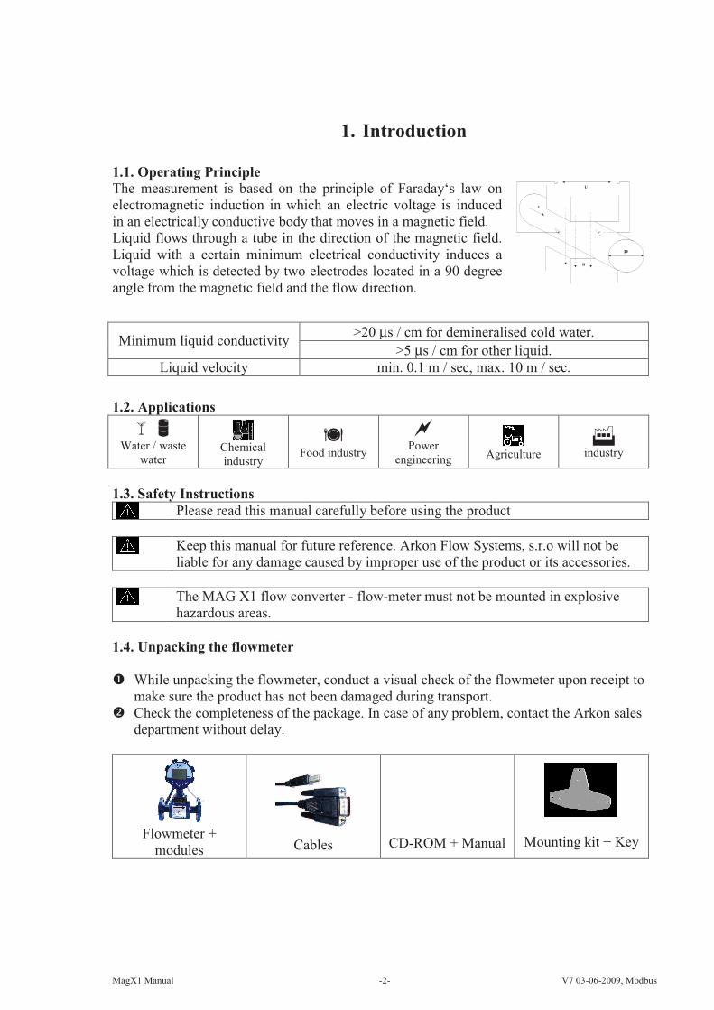
1.1. Operating Principle
The measurement is based on the principle of Faraday‘s law on
electromagnetic induction in which an electric voltage is induced
in an electrically conductive body that moves in a magnetic field.
Liquid flows through a tube in the direction of the magnetic field.
Liquid with a certain minimum electrical conductivity induces a
voltage which is detected by two electrodes located in a 90 degree
angle from the magnetic field and the flow direction.
1.2. Applications
Water / waste
water Chemical
industry
Food industry
Power
engineering Agriculture
industry
1.3. Safety Instructions
Please read this manual carefully before using the product
Keep this manual for future reference. Arkon Flow Systems, s.r.o will not be
liable for any damage caused by improper use of the product or its accessories.
The MAG X1 flow converter - flow-meter must not be mounted in explosive
hazardous areas.
1.4. Unpacking the flowmeter
While unpacking the flowmeter, conduct a visual check of the flowmeter upon receipt to
make sure the product has not been damaged during transport.
Check the completeness of the package. In case of any problem, contact the Arkon sales
department without delay.
Flowmeter +
modules Cables CD-ROM + Manual Mounting kit + Key
Minimum liquid conductivity >20 µs / cm for demineralised cold water.
>5 µs / cm for other liquid.
Liquid velocity min. 0.1 m / sec, max. 10 m / sec.

MagX1 Manual -3- V7 03-06-2009, Modbus
2. Installation
2.1. Remote or Compact?
Any MagX1 flowmeter can be delivered in two versions; Compact or Remote. The compact
version has the transmitter unit connected directly to the sensor body. This version does not
require any further mounting or installation of the transmitter.
The remote version has a separated transmitter. It is connected to the sensor with a cable. The
cable entry into the sensor is protected by a junction box, which can be potted to IP68 (page 7).
The cable entry on the transmitter side is through a M16x1,5 gland.
The cable type used for the connection between sensor and transmitter for remote versions:
UNITRONIC® LiYCY (TP) 0035 830, 2x2x0,5
The MagX1 is equipped with an electronic board located inside the sensor neck. This board
sends a digital signal to the transmitter, unlike traditional flowmeters, which send an analogue
signal. This allows the MagX1 to carry its signal over much longer distances than conventional
flowmeters; up to 500m is possible.

MagX1 Manual -4- V7 03-06-2009, Modbus
>5
m
2.2. Sensor installation
Sensor dimensions can be found on page 47
Proper sensor installation is extremely important in order for your flowmeter to work correctly.
Below, you will find minimum sensor installation requirements that need to be respected at all
time.
Sensor installation requirements
All MagX1 sensors are supplied with a built in earthing electrode which is sufficient for all
applications with metal pipes and tanks. However on applications where all pipes and
tanks are manufactured from plastic, it is recommended that earthing rings are also
installed to ensure the maximum resistance of the sensor to earth is <1 ohm.
Sensor grounding with earthing rings
5xDN 3xDN 5xDN
3xDN
8°
Steel Pipe Plastic Pipe

MagX1 Manual -5- V7 03-06-2009, Modbus
2.3. Dry liner
Flowmeters with a Hard Rubber liner can show incorrect readings during the first 2-3 days after
installation. This is due to the fact that the time needed for transport and the time before
installation is long enough for the liner to dry out , and thus it changes shape/size. This change,
in effect, affects reading accuracy. Simply be keeping the meter wet, this problem solve itself
within 2-3 days and no other action is required at all.
2.4. Installation of the transmitter
In case of a compact flowmeter version, the transmitter will need no
further installation, and should be ready for use.
In case of a remote version, the following 4 steps are necessary.
Mount the transmitter to a wall, panel, or DIN-rail.
Wall mounting:
DIN-rail mounting:
Panel mounting:
The electronics have to be
protected against direct
sunlight and high
temperatures!
The transmitter housing
should be exposed to
minimal mechanical
strain only (max. 1kg)!
MagX1 Manual -6- V7 03-06-2009, Modbus
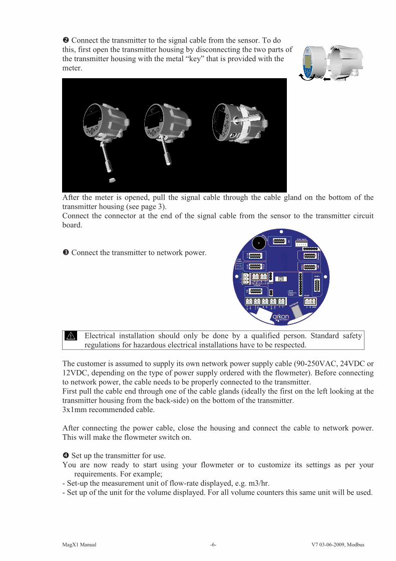
Connect the transmitter to the signal cable from the sensor. To do
this, first open the transmitter housing by disconnecting the two parts of
the transmitter housing with the metal “key” that is provided with the
meter.
After the meter is opened, pull the signal cable through the cable gland on the bottom of the
transmitter housing (see page 3).
Connect the connector at the end of the signal cable from the sensor to the transmitter circuit
board.
Connect the transmitter to network power.
Electrical installation should only be done by a qualified person. Standard safety
regulations for hazardous electrical installations have to be respected.
The customer is assumed to supply its own network power supply cable (90-250VAC, 24VDC or
12VDC, depending on the type of power supply ordered with the flowmeter). Before connecting
to network power, the cable needs to be properly connected to the transmitter.
First pull the cable end through one of the cable glands (ideally the first on the left looking at the
transmitter housing from the back-side) on the bottom of the transmitter.
3x1mm recommended cable.
After connecting the power cable, close the housing and connect the cable to network power.
This will make the flowmeter switch on.
Set up the transmitter for use.
You are now ready to start using your flowmeter or to customize its settings as per your
requirements. For example;
- Set-up the measurement unit of flow-rate displayed, e.g. m3/hr.
- Set up of the unit for the volume displayed. For all volume counters this same unit will be used.
MagX1 Manual -7- V7 03-06-2009, Modbus
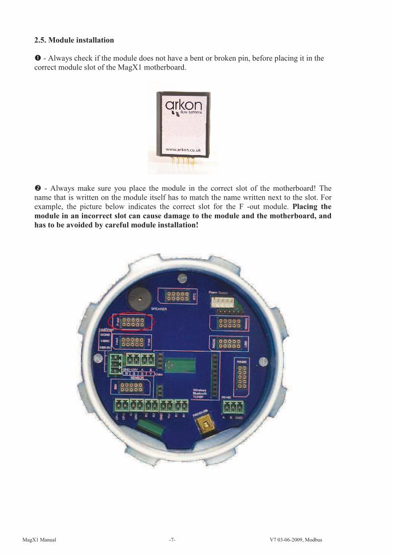
2.5. Module installation
- Always check if the module does not have a bent or broken pin, before placing it in the
correct module slot of the MagX1 motherboard.
- Always make sure you place the module in the correct slot of the motherboard! The
name that is written on the module itself has to match the name written next to the slot. For
example, the picture below indicates the correct slot for the F -out module. Placing the
module in an incorrect slot can cause damage to the module and the motherboard, and
has to be avoided by careful module installation!

MagX1 Manual -8- V7 03-06-2009, Modbus
- Check whether you are placing the module in the correct position. It does matter how you
turn the module to fit the slot! The white line around the actual slot on the motherboard
indicates the correct position of installation. The bevelled corner should be your point of
orientation (note the picture below).
- Now you can place the module in its slot:
These are examples of incorrect installations:
Example one: The F-out Module is placed in a different slot
Example two: The F-out Module is placed in the incorrect slot, and with the bevelled corner in
the wrong direction.
Any connection or disconnection of any module has to be done with network power
to the meter switched off.

MagX1 Manual -9- V7 03-06-2009, Modbus
2.6. Cables connections
The following diagram shows the connections of the cables between sensor and
transmitter.
2.7. Potting the remote sensor terminal box
To guarantee IP68 protection of the sensor, it is necessary to pot the sensor terminal box
properly. The proper way to do this is described below:
Plug the connectors into the sensor (white and green wire adjacent).
Screw the small terminal box to the sensor neck (4 screws).
Fill the terminal box completely with silicone, by squeezing it through the opening on
top of the box.
Close the small terminal box with the sealing screw.

MagX1 Manual -10- V7 03-06-2009, Modbus
Remote sensor with terminal box Preparing connections
Screw the sensor neck and box together Opening for terminal box potting
Completely filled terminal box Close the terminal box with the sealing screw

MagX1 Manual -11- V7 03-06-2009, Modbus
Module Name: Module Short Name: Symbol: Ordering Code:
MagX1
Transmitter UnitTransmitter “MagX1
Transmitter Unit”
The MagX1 Transmitter unit is the main part of the flowmeter. It consists of the MagX1
motherboard, a graphical display, touch-button controls and a transmitter housing.
Through the display and with help of the push buttons, you can go through the various menu’s
for data reading, configuration and setup of your flowmeter.
The following symbols are used in this manual and on the
flowmeter display.
ENTER UP
Esc LEFT
Back Menu
DOWN Selection
menu
RIGHT
Touch-buttons are working on capacitance principle therefore any conductive material close to
button's area will cause button press. Even water can do it so its strongly recommended to use
keylock when any presence of water is expected. 30 seconds after turning the flowmeter on,
touch-buttons autocalibration is started so function of the touch-buttons may be unstable.
The MagX1 transmitter has a keylock possibility. You can lock touch-
buttons by touching both the Esc and Enter together for longer than 1sec.
This will lock the flowmeter and there will be a lock symbol on display.
Touching the buttons will have no effect on flowmeters function. To
unlock buttons touch Esc and Enter together again. If flowmeter is in cleaning electrode there is
a lightning symbol on display.
Upon starting the flowmeter, you will automatically see the main screen of the menu.
3.1. Main screen
Total Volume
This is the total volume counter; the sum of all historical flows for a
particular flowmeter. The user is not able to zero this counter without
use of the service password. Direction of flow is ignored for this
counter (negative flow is calculated the same way as positive flow).
Positive Volume
This counter is only credited when the measured medium is flowing in
the chosen positive direction. In case the flow is 0, or if it is flowing in
the opposite (negative) direction, the number on the counter remains
the same.
Negative Volume
This counter works the same way as the positive volume counter, yet
in the opposite direction. In case the flow is 0, or flowing in the
designated positive direction, the number on this counter will remain
the same.

MagX1 Manual -12- V7 03-06-2009, Modbus
Auxiliary Volume
This is a 2nd
total volume counter. It works the same as the Total
Volume counter, yet with the only difference being that it can be reset
to 0 at any time, with User Settings password. Temperature
This item is a temperature indication for the measured medium.
You can cycle through these 5 indication screens by pressing the buttons on the transmitter.
It is possible to change the number of digits of the values displayed in the main screen:
decimal numbers -->
By using the buttons.
3.2. Flowmeter Menu
After pressing the button you get to into the root-menu.
From here, you can chose any of the sub-menu’s displayed in
the picture on the right.
Navigate with and select your choice with .
3.3. Info Menu
Date This item shows the current date according to
the transmitter’s setup if the Real-Time
Clock module is installed. It can be changed
in the User Settings menu.
Flow statistic This item gives flow statistics for a given
period of time. Data is taken from the
Memory module, which needs to be installed
for this function to work. More details on
page 36.
Unit No. Displays the serial number of the
motherboard. This number is allocated
during production by the manufacturer.
Sensor Unit
No.
Displays the serial number of the sensor.
This number is allocated during production
by the manufacturer.
Error (min) The number of minutes the device was not
measuring because of errors.
OK (min) The number of minutes that the device
measured correctly.
MagX1 Manual -13- V7 03-06-2009, Modbus
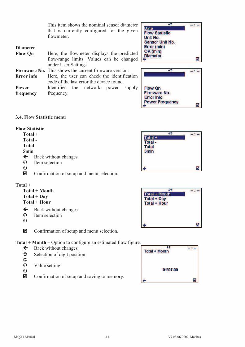
Diameter
This item shows the nominal sensor diameter
that is currently configured for the given
flowmeter.
Flow Qn Here, the flowmeter displays the predicted
flow-range limits. Values can be changed
under User Settings.
Firmware No. This shows the current firmware version.
Error info Here, the user can check the identification
code of the last error the device found.
Power
frequency
Identifies the network power supply
frequency.
3.4. Flow Statistic menu
Flow Statistic
Total +
Total -
Total
5min
Back without changes
Item selection
Confirmation of setup and menu selection.
Total +
Total + Month
Total + Day
Total + Hour
Back without changes
Item selection
Confirmation of setup and menu selection.
Total + Month – Option to configure an estimated flow figure.
Back without changes
Selection of digit position
Value setting
Confirmation of setup and saving to memory.

MagX1 Manual -14- V7 03-06-2009, Modbus
Statistics window
Back to menu
Scrolling through statistics
Total + Day - Option to configure an estimated flow figure.
Back without changes
Selection of digit position
Value setting
Confirmation of setup and saving to memory.
Statistics window
Back to menu
Scrolling through statistics
Total + Hour - Option to configure an estimated flow figure.
Back without changes
Selection of digit position
Value setting
Confirmation of setup and saving to memory.
Statistics window
Back to menu
Scrolling through statistics
Total -
Total - Month
Total - Day
Total - Hour
Back without changes
Item selection
Confirmation of setup and menu selection.

MagX1 Manual -15- V7 03-06-2009, Modbus
Total - Month - Option to configure an estimated flow figure.
Back without changes
Selection of digit position
Value setting
Confirmation of setup and saving to memory.
Statistics window
Back to menu
Scrolling through statistics
Total - Day - Option to configure an estimated flow figure.
Back without changes
Selection of digit position
Value setting
Confirmation of setup and saving to memory.
Statistics window
Back to menu
Scrolling through statistics
Total - Hour - Option to configure an estimated flow figure.
Back without changes
Selection of digit position
Value setting
Confirmation of setup and saving to memory.
Statistics window
Back to menu
Scrolling through statistics

MagX1 Manual -16- V7 03-06-2009, Modbus
Total
Total Month
Total Day
Total Hour
Back without changes
Item selection
Confirmation of setup and menu selection.
Total Month - Option to configure an estimated flow figure.
Back without changes
Item selection
Value setting
Confirmation of setup and menu selection.
Statistics window
Back to menu
Scrolling through statistics
Total Day - Option to configure an estimated flow figure.
Back without changes
Selection of digit position
Value setting
Confirmation of setup and saving to memory.
Statistics window
Back to menu
Scrolling through statistics
Total - Hour - Option to configure an estimated flow figure.
Back without changes
Selection of digit position
Value setting
Confirmation of setup and saving to memory.

MagX1 Manual -17- V7 03-06-2009, Modbus
Statistics window
Back to menu
Scrolling through statistics
3.5. Display menu
Unit Flow
Setup of the displayed measurement unit for current
flow.
UKG / min UK gallon per minute
USG / min US gallon per minute
m3 / h Cubic meters per hour
l / min Litres per minute
l / s Litres per second
(item selection confirm , selection identification back )
Unit volume
Setup of the displayed measurement unit for total flow.
UKG UK gallon
USG US gallon
m3 Cubic meter
l Litre
(item selection confirm , selection identification back )
5 min - Option to configure an estimated flow figure. Back without changes
Selection of digit position
Value setting
Confirmation of setup and saving to memory.
Statistics window
Back to menu
Scrolling through statistics

MagX1 Manual -18- V7 03-06-2009, Modbus
Unit temperature
Setup of the displayed measurement unit of
temperature indication.
C Degrees Celsius
F Degrees Fahrenheit
(item selection confirm , selection identification back )
Contrast
Contrast of the display setup.
Possible range: 0 – 100 %
Back with no change
Selection of digit position
Value setting
Confirmation of setup and saving to memory.
Language
Menu language setup.
ENG English
SPA Spanish
(item selection confirm , selection identification back )

MagX1 Manual -19- V7 03-06-2009, Modbus
3.6. User Settings Menu
To enter the User Settings menu, it is necessary to enter the user password. The default
factory setting is 1111. See page 27 for user password settings.
After entering the correct User Password, you get into
the User Settings Menu. By selecting your choice, you
can make changes to specific settings.
Measurement
This option allows for selecting flow measurement to be on or
off.
RUN The device is measuring, the totalisers are active.
STOP The display will show a value, yet the totalisers
are off.
(item selection confirm , selection identification back )
MagX1 Manual -20- V7 03-06-2009, Modbus
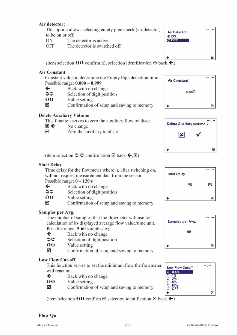
Air detector:
This option allows selecting empty pipe check (air detector)
to be on or off.
ON The detector is active
OFF The detector is switched off
(item selection confirm , selection identification back )
Air Constant
Constant value to determine the Empty Pipe detection limit.
Possible range: 0.000 – 0.999
Back with no change
Selection of digit position
Value setting
Confirmation of setup and saving to memory.
Delete Auxiliary Volume
This function serves to zero the auxiliary flow totaliser.
No change
Zero the auxiliary totaliser
(item selection confirmation back ,)
Start Delay
Time delay for the flowmeter where it, after switching on,
will not request measurement data from the sensor.
Possible range: 0 – 120 s
Back with no change
Selection of digit position
Value setting
Confirmation of setup and saving to memory.
Samples per Avg.
The number of samples that the flowmeter will use for
calculation of its displayed average flow value/time unit.
Possible range: 5-60 samples/avg
Back with no change
Selection of digit position
Value setting
Confirmation of setup and saving to memory.
Low Flow Cut-off
This function serves to set the minimum flow the flowmeter
will react on.
Back with no change
Value setting
Confirmation of setup and saving to memory.
(item selection confirm selection identification back )
Flow Qn

MagX1 Manual -21- V7 03-06-2009, Modbus
This function serves to setup the expected flow-rate.
Possible range: 0 – 10000 l/s
Back with no change
Selection of digit position
Value setting
Confirmation of setup and saving to memory.
Invert Flow
This function serves to change the definition of flow
direction.
Back with no change
Choice selection
Confirmation of setup and saving to memory.
Current Loop
Settings Signal
Direct Driving
Back with no change
Item selection
Confirmation of setup and saving to memory.
Settings Signal
This function serves to select which signal the output
should be giving.
Back with no change
Choice selection
Confirmation of setup and saving to
memory.
Flow + Output: 10mA for any positive flow.
Flow - Output: 10mA for any negative flow.
Error Output: 10mA, for any error identified by
the device. The signal can be cancelled
by pressing any push button on the
flowmeter.
Air Detect Output: 10mA, during air detection
(empty pipe).
Fixed Output: fixed output of 10mA
Direct Driving Output: Direct Driving – setup is below
OFF Output: fixed output of 4mA

MagX1 Manual -22- V7 03-06-2009, Modbus
Direct Driving
This function serves to set flow values in relation to current
output. Possible range: 0.000 – 10000 l/s, 4 – 20mA
Back with no change
Selection of digit position
Change of value
Confirmation of setup and saving to memory.
Flow
min.-max
Setup of measurement flow-range (only positive values)
Current
min.-max
Setup of the current output range, corresponding to the actual flow-rate
within the given range.
When changing an item for the current
loop output, all settings for the voltage output
are to be changed, to make sure there will be no
signal conflict at the output port. The output that
is not used has to be switched off (Settings –
Signal – OFF).
Calibration
This function serves to modify current loop output signal.
Possible range: 4 – 20mA, 0.5000 – 1.5000
Back with no change
Selection of digit position
Change of value
Confirmation of setup and saving to
memory.
Calibration
point 1,2
Setup of calibration point 1, 2. First point must be less than second point.
Calibration
constant 1,2
Setup of calibration constant for first and for second calibration point.
Formula for calibration constant calculation:
Expected value: 6 mA, Measured value: 6.1 mA
Calibration point one: 6mA
Calibration constant one = = 0.9836
Expected value: 18 mA, Measured value: 17.9 mA
Calibration point two: 18mA
Calibration constant two = = 1.0056
Voltage Output
Settings Signal
Direct Driving
Back with no change
Item selection
Confirmation of setup and saving to
memory.
min max
max
min
Flow
Current
6
6.1
18
17.9min max
max
min
Flow
Current before
after

MagX1 Manual -23- V7 03-06-2009, Modbus
Settings Signal
This function serves to select which signal the output
should be giving.
Back with no change
Item selection
Confirmation of setup and saving to
memory.
Flow + Output: 5V for any positive flow.
Flow - Output: 5V for any negative flow.
Error Output: 5V, for any error identified by
the device. The signal can be cancelled
by pressing any push button on the
flowmeter.
Air Detect Output: 5V, during air detection (empty pipe).
Fixed Fixed output of 5V
Direct Driving Output: Direct Driving – setup is below
OFF Output is OFF (0V).
Direct Driving
This function serves to set flow values in relation to voltage
output. Possible range: 0.000 – 10000 l/s, 0 – 10V
Back with no change
Selection of digit position
Change of value
Confirmation of setup and saving to
memory.
Flow
min.-max
Setup of measurement flow-range (only positive values)
Voltage min.-
max
Setup of the voltage output range, corresponding to the actual flow-
rate within the given range.
• When changing an item for the Voltage output,
all settings for the current output are to be changed, to
make sure there will be no signal conflict at the
output port. The output that is not used has to be
switched off (Settings – Signal – OFF).
Relay 1
Settings Signal
Comparator
Back with no change
Item selection
Confirmation of setup and saving to
memory.
min max
max
min
Flow
Voltage
MagX1 Manual -24- V7 03-06-2009, Modbus
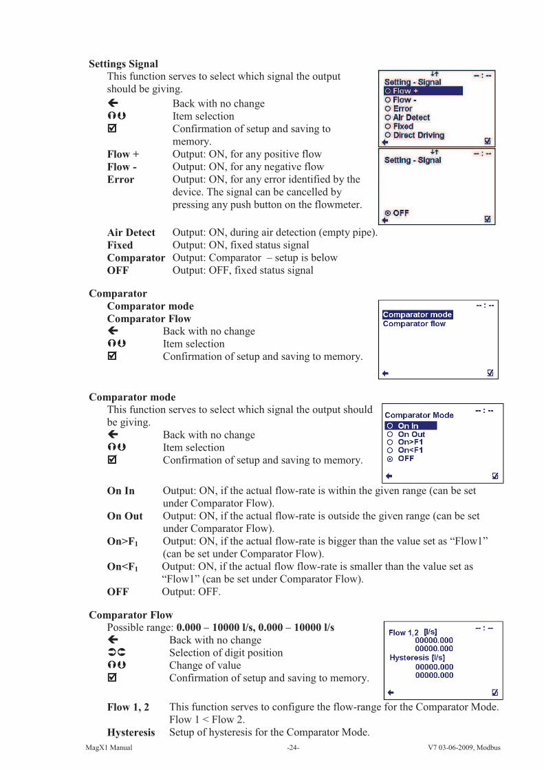
Settings Signal
This function serves to select which signal the output
should be giving.
Back with no change
Item selection
Confirmation of setup and saving to
memory.
Flow + Output: ON, for any positive flow
Flow - Output: ON, for any negative flow
Error Output: ON, for any error identified by the
device. The signal can be cancelled by
pressing any push button on the flowmeter.
Air Detect Output: ON, during air detection (empty pipe).
Fixed Output: ON, fixed status signal
Comparator Output: Comparator – setup is below
OFF Output: OFF, fixed status signal
Comparator
Comparator mode
Comparator Flow
Back with no change
Item selection
Confirmation of setup and saving to memory.
Comparator mode
This function serves to select which signal the output should
be giving.
Back with no change
Item selection
Confirmation of setup and saving to memory.
On In Output: ON, if the actual flow-rate is within the given range (can be set
under Comparator Flow).
On Out Output: ON, if the actual flow-rate is outside the given range (can be set
under Comparator Flow).
On>F1 Output: ON, if the actual flow-rate is bigger than the value set as “Flow1”
(can be set under Comparator Flow).
On<F1 Output: ON, if the actual flow flow-rate is smaller than the value set as
“Flow1” (can be set under Comparator Flow).
OFF Output: OFF.
Comparator Flow
Possible range: 0.000 – 10000 l/s, 0.000 – 10000 l/s
Back with no change
Selection of digit position
Change of value
Confirmation of setup and saving to memory.
Flow 1, 2 This function serves to configure the flow-range for the Comparator Mode.
Flow 1 < Flow 2.
Hysteresis Setup of hysteresis for the Comparator Mode.

MagX1 Manual -25- V7 03-06-2009, Modbus
When configuring Relay 1, the following is valid::
Settings - Signal or Comparator mode. Any unused setting needs to be OFF. To switch off
Relay 1, both options need to be OFF. When configuring Settings – Signal to any other value
than OFF, the Comparator Mode setting is automatically changed to OFF.
On In:
On Out:
On > F1:
On < F1:
Relay 2
Litres/1(Q+)
Litres/1(Q-)
Dosing
Back with no change
Item selection
Confirmation of setup and saving to memory.
Litres/1 (Q+)
This function serves to configure the positive flow volume
after which a 1s output pulse is generated through Relay 2.
In case of a power failure, the output will start counting
volume from 0. Possible range: 0.000 – 99999 l
Back with no change
Selection of digit position
Change of value
Confirmation of setup and saving to memory.
ON
OFF
F1 F1 + H1 F2F2 – H2
ON
OFF
F1 F1 + H1
ON
OFF
F1 F1 + H1
ON
OFF
F1 F1 + H1 F2 – H2 F2
MagX1 Manual -26- V7 03-06-2009, Modbus
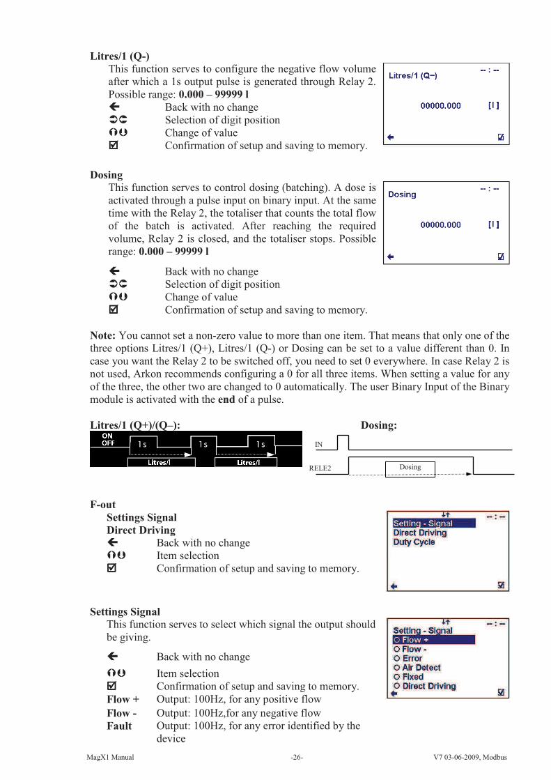
Litres/1 (Q-)
This function serves to configure the negative flow volume
after which a 1s output pulse is generated through Relay 2.
Possible range: 0.000 – 99999 l
Back with no change
Selection of digit position
Change of value
Confirmation of setup and saving to memory.
Dosing
This function serves to control dosing (batching). A dose is
activated through a pulse input on binary input. At the same
time with the Relay 2, the totaliser that counts the total flow
of the batch is activated. After reaching the required
volume, Relay 2 is closed, and the totaliser stops. Possible
range: 0.000 – 99999 l
Back with no change
Selection of digit position
Change of value
Confirmation of setup and saving to memory.
Note: You cannot set a non-zero value to more than one item. That means that only one of the
three options Litres/1 (Q+), Litres/1 (Q-) or Dosing can be set to a value different than 0. In
case you want the Relay 2 to be switched off, you need to set 0 everywhere. In case Relay 2 is
not used, Arkon recommends configuring a 0 for all three items. When setting a value for any
of the three, the other two are changed to 0 automatically. The user Binary Input of the Binary
module is activated with the end of a pulse.
Litres/1 (Q+)/(Q–): Dosing:
F-out
Settings Signal
Direct Driving
Back with no change
Item selection
Confirmation of setup and saving to memory.
Settings Signal
This function serves to select which signal the output should
be giving.
Back with no change
Item selection
Confirmation of setup and saving to memory.
Flow + Output: 100Hz, for any positive flow
Flow - Output: 100Hz,for any negative flow
Fault Output: 100Hz, for any error identified by the
device
IN
RELE2 Dosing

MagX1 Manual -27- V7 03-06-2009, Modbus
Air
Detect
Output: 100Hz, during air detection (empty pipe).
Fixed Output: 100Hz fixed output
OFF Output: OFF
Direct Driving
This function serves to set flow values in relation to
frequency output. Possible range:
0.000 – 10000 l/s, 0 – 1000 Hz
Back with no change
Change of value
Selection of digit position
Confirmation of setup and saving to memory.
Flow min. - max. Setup of the active flow-range for the Frequency output module.
F min. - max Configuration of the Frequency output range, corresponding to the
actual flow-rate within the given range.
Minimal frequency 2 Hz
Duty Cycle
Function to set duty cycle of the Frequency output.
Percentage of high level.
Possible range: 1 – 99 %
Back with no change
Selection of digit position
Change of value
Confirmation of setup and saving to memory.
Speaker output
This function serves to select which signal the output should
be giving.
Back with no change
Item selection
Confirmation of setup and saving to memory.
Flow +/- Sound signal when flow direction changes
Fault Sound signal for any error identified by the device. This signal is active until
stopped by pressing any push button on the flowmeter.
Air detect Sound signal during air detection (empty pipe).
Fixed Constant sound signal
OFF Sound signalling switched off.
min max
max
min
Flow
F [Hz]

MagX1 Manual -28- V7 03-06-2009, Modbus
Load Default Settings
This function will load default factory settings.
Back with no change
Loads default settings
(item selection confirm , back )
Date Setting
Function to set date.
Back with no change
Change of value
Selection of digit position
Confirmation of setup and saving to memory.
Date
format.
DD\MM\YY
Time Setting
This function serves to set current time
Back with no change
Change of value
Selection of digit position
Confirmation of setup and saving to memory.
Time
format.
HH:MM
Password Setup
This function serves to setup the flowmeter user password.
Possible range: 0000 – 9999
Back with no change
Change of value
Selection of digit position
Confirmation of setup and saving to memory.
Modbus
Slave Address
Baud Rate
Parity
Interframe Spacing
Response Delay
Back with no change
Item selection
Confirmation
Slave Address
Modbus device address (Factory settings: 1)
Back with no change
Selection of digit position
Change of value
Confirmation of setup and saving to memory.

MagX1 Manual -29- V7 03-06-2009, Modbus
Baud Rate
Setup communication speed (Factory settings: 9600)
Back with no change
Value setting
Confirmation of setup and saving to memory.
(item selection confirm selection identification back )
Parity
Setup communication parameters (Factory settings: Even, 1
stopbit)
Back with no change
Value setting Confirmation of setup and saving to memory.
(item selection confirm selection identification back )
Interframe Spacing
The minimum interframe space between two MODBUS
RTU messages in sequence (specified as 3.5 characters) is
configurable. Possible range: 3.5 – 25.0
Back with no change
Selection of digit position
Change of value
Confirmation of setup and saving to memory.
Response Delay
The minimum time from when a slave receives a request
and until it returns a response. This makes it possible to
send data to slow masters without overwhelming its
receiver. (Factory setting: 50) Possible range: 0 – 255 ms
Back with no change
Selection of digit position
Change of value
Confirmation of setup and saving to memory.
Electrode Cleaning
Power
Clean Time
Start Now
Back with no change
Item selection
Confirmation
MagX1 Manual -30- V7 03-06-2009, Modbus
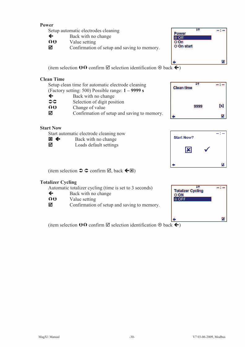
Power
Setup automatic electrodes cleaning
Back with no change
Value setting
Confirmation of setup and saving to memory.
(item selection confirm selection identification back )
Clean Time
Setup clean time for automatic electrode cleaning
(Factory setting: 500) Possible range: 1 – 9999 s
Back with no change
Selection of digit position
Change of value
Confirmation of setup and saving to memory.
Start Now
Start automatic electrode cleaning now
Back with no change
Loads default settings
(item selection confirm , back )
Totalizer Cycling
Automatic totalizer cycling (time is set to 3 seconds)
Back with no change
Value setting
Confirmation of setup and saving to memory.
(item selection confirm selection identification back )

MagX1 Manual -31- V7 03-06-2009, Modbus
3.7. Service Settings Menu
To enter this part of the menu, it is necessary to enter the Service Password.
Error delete:
This option serves to zero the totaliser for number of minutes
the flowmeter signalised an error.
Item selection
No change
Resets error minute totaliser
OK delete
This option serves to zero the totaliser for number of minutes
of operation.
Item selection
No change
Resets error minute totaliser
Delete volume –
Option to zero the totaliser for negative flow.
Item selection
Confirmation
Back without change
Delete volume +
Option to zero the totaliser for positive flow.
Item selection
Confirmation
Back without change

MagX1 Manual -32- V7 03-06-2009, Modbus
Delete volume total
Option to zero the totaliser for total flow.
Item selection
Confirmation
Back without change
Datalogger delete:
This function serves to erase the memory chip of the memory
module, which holds a list of measured values.
No change
Delete all memory values
(item selection confirmation back ,)
Flow Simulation
Switching on/off the flow simulation status
ON Flow Simulatin status is ON
OFF Flow Simulatin status is OFF
Item selection
Confirmation
(selection identification , back )
Simulated Flow
Simulation flow percentage of Flow Qn
(Factory setting: 50) Possible range: 0 – 100 %
Back with no change
Selection of digit position
Change of value
Confirmation of setup and saving to memory.
3.8. Factory Settings Menu
To enter this part of the menu, it is necessary to enter the Factory Password.
This function is only available to Arkon staff in the Arkon workshop

MagX1 Manual -33- V7 03-06-2009, Modbus
3.9. Authorize Menu
To enter this part of the menu, it is necessary to enter the Autorize Password.
This function is only available to Arkon staff in the Arkon workshop.
Authorize - Password Setup
Here, it is possible to change a forgotten user password. It
is necessary to call the Arkon sales office and provide the
serial number. The authorisation number is provided based
on this serial number.
Item selection
Confirmation
Back without change
Enter value between 0000 and 9999.
MagX1 Manual -34- V7 03-06-2009, Modbus
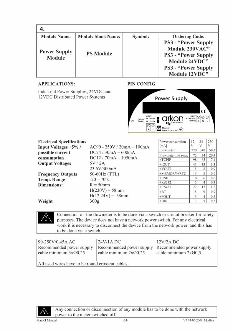
Module Name: Module Short Name: Symbol: Ordering Code:
Power Supply
Module PS Module
PS3 - “Power Supply
Module 230VAC”
PS3 - “Power Supply
Module 24VDC”
PS3 - “Power Supply
Module 12VDC”
APPLICATIONS: PIN CONFIG
Industrial Power Supplies, 24VDC and
12VDC Distributed Power Systems
Electrical Specifications Power consumtion
[mA]
12
V
24
V
230
V
Flowmeter 770 340 50,3
Flowmeter, no sens. 73 34 20,4
+TCPIP 98 65 17,1
+IOUT 41 33 3,3
+VOUT 15 8 0,9
+MEMORY+RTC 15 8 0,9
+USB 10 6 0,6
+RS232 5 4 0,3
+RS485 22 17 1,8
+BT 15 9 0,9
+FOUT 5 4 0,5
+BIN 7 5 0,5
Input Voltages ±5% /
possible current
consumption
AC90 - 250V / 20mA – 100mA
DC24 / 30mA – 600mA
DC12 / 70mA – 1050mA
Output Voltages 5V / 2A
23.6V/300mA
Frequency Outputs 50-60Hz (TTL)
Temp. Range -20 – 70°C
Dimensions: R = 50mm
H(230V) = 58mm
H(12,24V) = 58mm
Weight 300g
Connection of the flowmeter is to be done via a switch or circuit breaker for safety
purposes. The device does not have a network power switch. For any electrical
work it is necessary to disconnect the device from the network power, and this has
to be done via a switch.
90-250V/0,45A AC
Recommended power supply
cable minimum 3xØ0,25
24V/1A DC
Recommended power supply
cable minimum 2xØ0,25
12V/2A DC
Recommended power supply
cable minimum 2xØ0,5
All used wires have to be round crosscut cables.
Any connection or disconnection of any module has to be done with the network
power to the meter switched off.
MagX1 Manual -35- V7 03-06-2009, Modbus
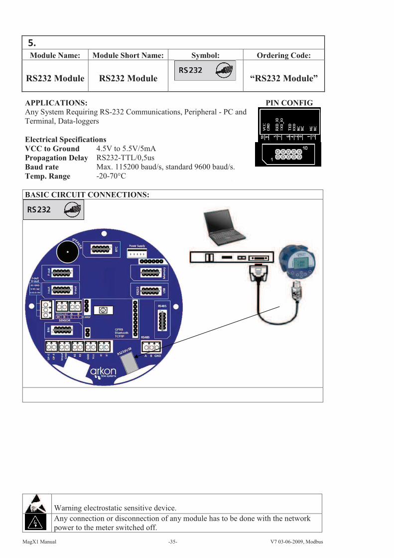
Module Name: Module Short Name: Symbol: Ordering Code:
RS232 Module RS232 Module “RS232 Module”
APPLICATIONS: PIN CONFIG
Any System Requiring RS-232 Communications, Peripheral - PC and
Terminal, Data-loggers
Electrical Specifications
VCC to Ground 4.5V to 5.5V/5mA
Propagation Delay RS232-TTL/0,5us
Baud rate Max. 115200 baud/s, standard 9600 baud/s.
Temp. Range -20-70°C
BASIC CIRCUIT CONNECTIONS:
Warning electrostatic sensitive device.
Any connection or disconnection of any module has to be done with the network
power to the meter switched off.

MagX1 Manual -36- V7 03-06-2009, Modbus
Module Name: Module Short Name: Symbol: Ordering Code:
Real-Time
Clock Module RTC Module “Real-Time Clock
Module”
APPLICATIONS: PIN CONFIG
Real-Time Clock Counts Seconds, Minutes, Hours, Date of the Month,
Month, Day of the Week, and Year with leap-year compensation valid
Up to 2100, Data-loggers
Electrical Specifications
VCC to Ground 2V to 5.5V/0.5mA, 1.3mA
CLK Frequency Vcc=2V-Max. 0.5 MHz
Vcc=5V- Max. 2.0 MHz
Temp. Range -20-70°C
BASIC CIRCUIT CONNECTIONS:
This module is prerequisite when using the Memory (data-logger) module.
Warning electrostatic sensitive device.
Any connection or disconnection of any module has to be done with the network
power to the meter switched off.

MagX1 Manual -37- V7 03-06-2009, Modbus
Module Name: Module Short Name: Symbol: Ordering Code:
USB Module USB Module “USB Module”
APPLICATIONS: PIN CONFIG
Any System Requiring, USB Communications, Peripheral - PC and
Terminal, Data-loggers. USB 1.1 and USB 2.0 compatible
Electrical Specifications
VCC to Ground 4.35V to 5.25V/25mA
Baud rate Max. 115200 baud/s,
standard 9600 baud/s.
Temp. Range -20-70°C
BASIC CIRCUIT CONNECTIONS:
VIRTUAL COM PORT (VCP) DRIVERS:
http://www.ftdichip.com/Drivers/VCP.htm
Driver installation guide: http://www.ftdichip.com/Documents/InstallGuides.htm
Warning electrostatic sensitive device.
Any connection or disconnection of any module has to be done with the network
power to the meter switched off.

MagX1 Manual -38- V7 03-06-2009, Modbus
Module Name: Module Short Name: Symbol: Ordering Code:
Frequency
Output ModuleFreq-Out Module “Frequency
Output Module”
APPLICATIONS: PIN CONFIG
Industrial Automation, Industrial process, Control, Test Systems, Smart
Transmitter
Electrical Specifications
VCC to Ground 4.5V to 5.5V/25mA
VOPK Typ. 5V, Max. 48V
IOPK Max. 50mA
Frequency out
Duty Cycle
2 Hz – 1000 Hz
1 – 99 %
Temp. Range -20-70°C
BASIC CIRCUIT CONNECTIONS
Optimal resistance of the collectors in relation to the maximum
frequency 12kHz.
VCC R1
5 V 1k8
12 V 3k3
24 V 6k8
Duty cycle can be changed in User Settings – F-Out – Duty Cycle (1 - 99 %)
Warning electrostatic sensitive device.
Any connection or disconnection of any module has to be done with the network
power to the meter switched off.

MagX1 Manual -39- V7 03-06-2009, Modbus
Module Name: Module Short Name: Symbol: Ordering Code:
Memory Module Memory Module
“Memory
Module”
BASIC CIRCUIT CONNECTIONS:
For proper functioning of this module, the
Real-Time Clock (RTC) Module is
prerequisite.
Important: Before you save your first data, you need to
set the correct time and date; else all saved
data will be without proper time reference!
To be able to do this, you also need to use the
MagX1 RTC (Real-Time Clock) Module.
(page 32)
These values can be uploaded to a PC with the help of special software, which is supplied
together with the configuration SW and the manual.
If capacity runs out before all data is deleted from memory, then the module will
automatically overwrite the oldest values with new ones! In case memory is used, it has to be
“cleaned” at least once every year (Datalogger Delete function), else older data will be lost.
The Memory Module has sufficient capacity for storing flow-data for a 12-month operation
period without overwriting older data.
Save intervals:
- 5-minute interval record of flow averages (8928 samples in 1 month)
- 1-hour interval record of total flow (744 samples in 1 month)
- 24-hour interval record of total flow (31 samples in 1 month)
- Monthly interval record of total flow (1 sample in 1 month)
You can view this data in menu 1.2. Flow Statistics (3.4. Flow statistic menu; page 13)
Warning electrostatic sensitive device.
Any connection or disconnection of any module has to be done with the network
power to the meter switched off.
APPLICATIONS: PIN CONFIG
Data-loggers, Memory capacity is 1 MB (megabyte)
Electrical Specifications
VCC to Ground 3.2V to 5V/2-15mA
Max frequency SCK 20MHz
Temp. Range -20-70°C
5.0V-tolerant Inputs: SI, SCK, CS, RES., WP Pins

MagX1 Manual -40- V7 03-06-2009, Modbus
Module Name: Module Short Name: Symbol: Ordering Code:
RS485 Module RS485 Module “RS485 Module”
APPLICATIONS: PIN CONFIG
Industrial Automation, Industrial Process Control, Peripheral - PC and
Terminal, Data-loggers
Electrical Specifications
VCC to Ground 4.5V to 5.5V / 55mA
Baud rate Max. 115200 baud/s
Temp. Range -20-70°C
BASIC CIRCUIT CONNECTIONS:
Multi-Node Network with End Termination Using
Module RS485
For computers that do not have an RS485 port, we can provide an RS485 to RS232 or an RS485 to
USB convertor. Please contact the Arkon sales office for details.
Terminator Rt with resistance 100ΩΩΩΩ should be connect to the end of line RS-485.
Warning electrostatic sensitive device.
Any connection or disconnection of any module has to be done with the network
power to the meter switched off.
MagX1 Manual -41- V7 03-06-2009, Modbus
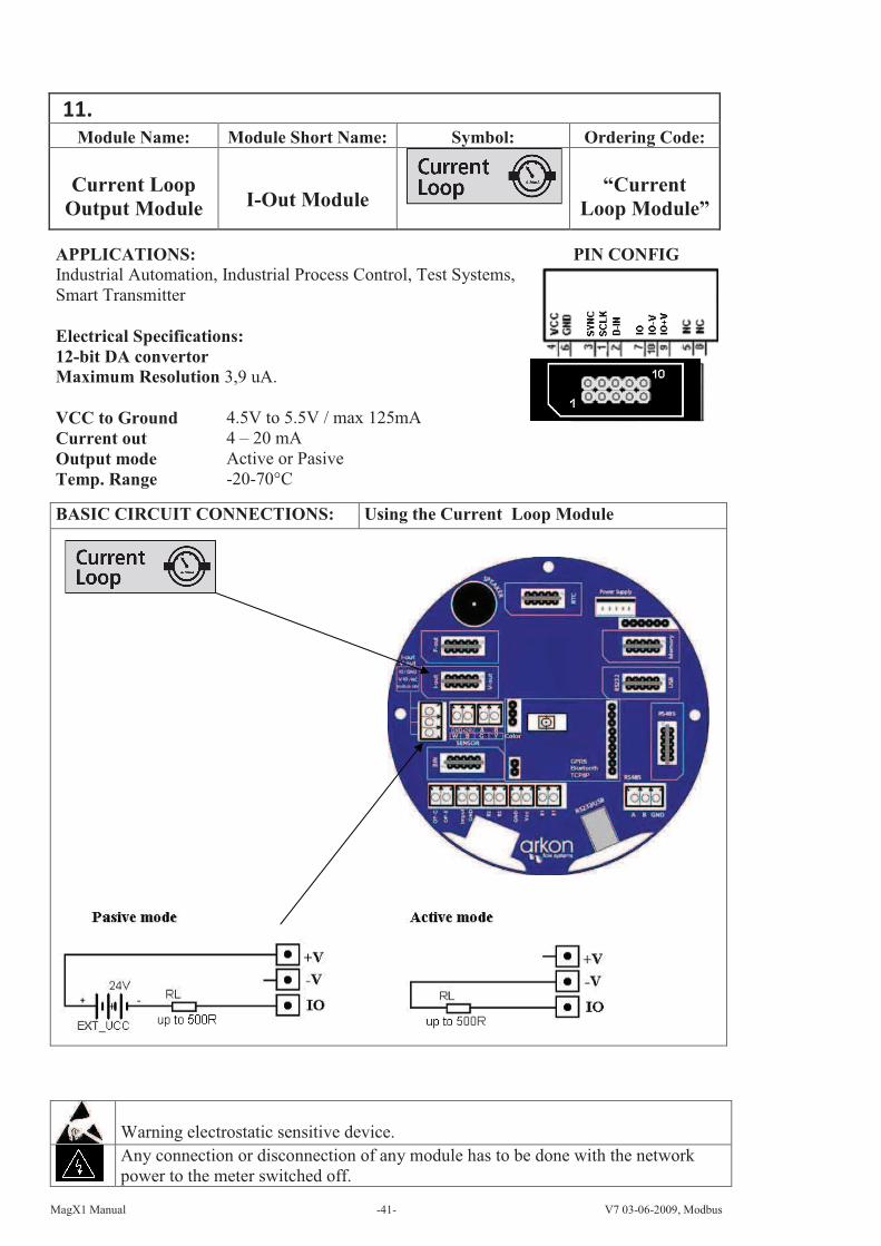
Module Name: Module Short Name: Symbol: Ordering Code:
Current Loop
Output Module I-Out Module “Current
Loop Module”
APPLICATIONS: PIN CONFIG
Industrial Automation, Industrial Process Control, Test Systems,
Smart Transmitter
Electrical Specifications:
12-bit DA convertor
Maximum Resolution 3,9 uA.
VCC to Ground 4.5V to 5.5V / max 125mA
Current out 4 – 20 mA
Output mode Active or Pasive
Temp. Range -20-70°C
BASIC CIRCUIT CONNECTIONS: Using the Current Loop Module
Warning electrostatic sensitive device.
Any connection or disconnection of any module has to be done with the network
power to the meter switched off.

MagX1 Manual -42- V7 03-06-2009, Modbus
Module Name: Module Short Name: Symbol: Ordering Code:
Binary In- and
Output Module BIN Module
“Binary
Module”
APPLICATIONS: PIN CONFIG
Industrial Automation, Industrial Process Control, Test
Systems, Smart Transmitter
Electrical Specifications
VCC to Ground 4.5V to 14V / 25mA
Input Max. 14V, Typ. 5V, Min. 1.6V
Switching Outputs Max. 200mA
Temp. Range -20-70°C
Output frequency Max 1 puls per second
BASIC CIRCUIT CONNECTIONS: Using the Binary Module:
Recommended connections:
Warning electrostatic sensitive device.
Any connection or disconnection of any module has to be done with the network
power to the meter switched off.
MagX1 Manual -43- V7 03-06-2009, Modbus
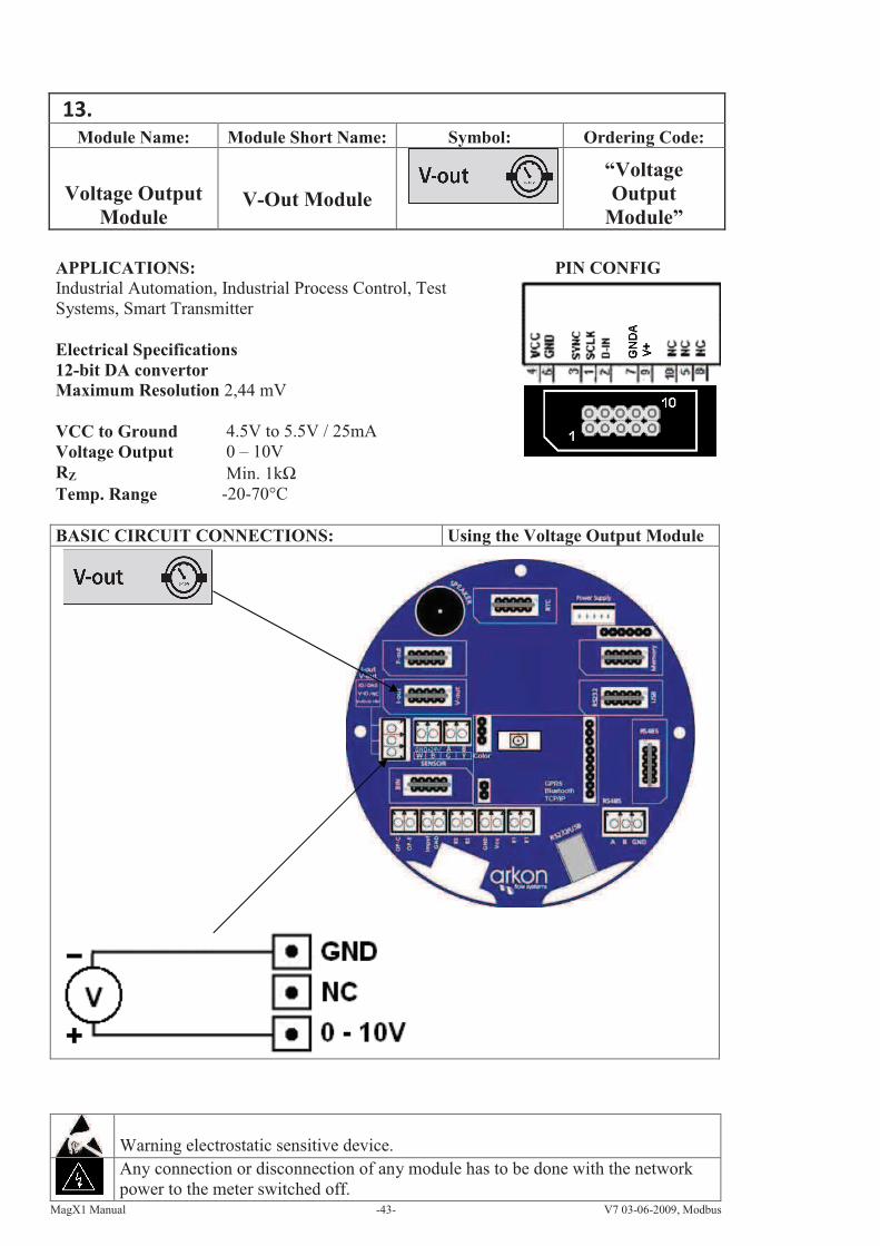
Module Name: Module Short Name: Symbol: Ordering Code:
Voltage Output
Module V-Out Module
“Voltage
Output
Module”
APPLICATIONS: PIN CONFIG
Industrial Automation, Industrial Process Control, Test
Systems, Smart Transmitter
Electrical Specifications
12-bit DA convertor
Maximum Resolution 2,44 mV
VCC to Ground 4.5V to 5.5V / 25mA
Voltage Output 0 – 10V
RZ Min. 1kΩ
Temp. Range -20-70°C
BASIC CIRCUIT CONNECTIONS: Using the Voltage Output Module
Warning electrostatic sensitive device.
Any connection or disconnection of any module has to be done with the network
power to the meter switched off.
MagX1 Manual -44- V7 03-06-2009, Modbus
Module Name: Module Short Name: Symbol: Ordering Code:
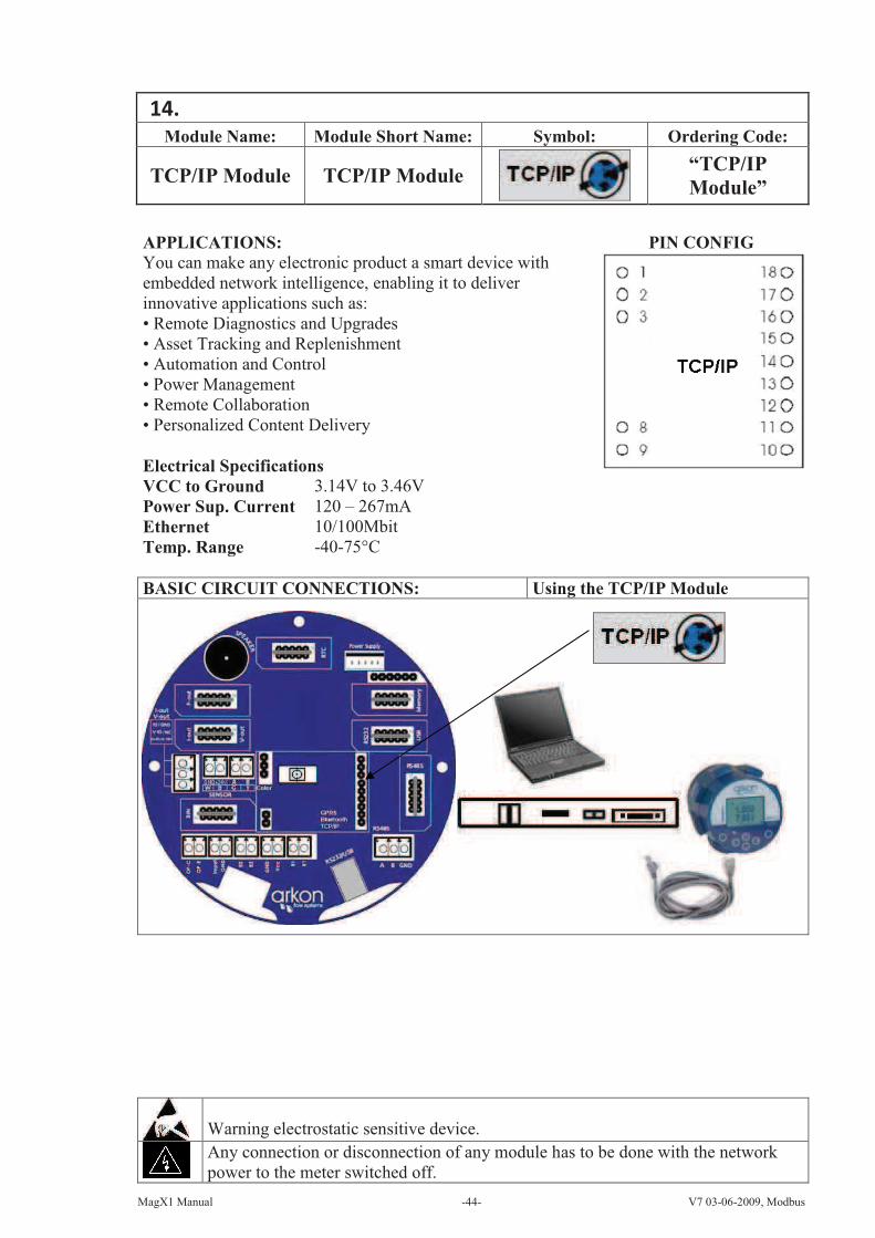
TCP/IP Module TCP/IP Module “TCP/IP
Module”
APPLICATIONS: PIN CONFIG
You can make any electronic product a smart device with
embedded network intelligence, enabling it to deliver
innovative applications such as:
• Remote Diagnostics and Upgrades
• Asset Tracking and Replenishment
• Automation and Control
• Power Management
• Remote Collaboration
• Personalized Content Delivery
Electrical Specifications
VCC to Ground 3.14V to 3.46V
Power Sup. Current 120 – 267mA
Ethernet 10/100Mbit
Temp. Range -40-75°C
BASIC CIRCUIT CONNECTIONS: Using the TCP/IP Module
Warning electrostatic sensitive device.
Any connection or disconnection of any module has to be done with the network
power to the meter switched off.

MagX1 Manual -45- V7 03-06-2009, Modbus
Module Name: Module Short Name: Symbol: Ordering Code:
BLUETOOTH
Module BT Module
“BLUETOOTH
Module”
APPLICATIONS: PIN CONFIG
Wireless control of and communication between transmitter
and PC or PLC systems
Any System Requiring BlueTooth Communications
Electrical Specifications
VCC to Ground 3.6V to 6.0V
Power Sup. Current 120mA
Baud Rate Max. 460.8 Kbaud/s
Carrier Frequency 2.402 – 2.480 GHz
Range 100m (class 1)
Temp. Range –10 - +70°C
BASIC CIRCUIT CONNECTIONS: Using the TCP/IP Module
Warning!: There is a condition that must be fulfilled for the Bluetooth module to be able to
operate correctly: line speed of the communication protocol MODBUS must be set up on
19200Bd, Parity none, 1 stop bit. If there is a different setting the communication will not
work. You can find the setting in the following MagX1 flow meter menu: "Menu /
User settings / Modbus / Baud rate" and "Menu / User settings / Modbus / Parity".
Warning electrostatic sensitive device.
Any connection or disconnection of any module has to be done with the network
power to the meter switched off.
MagX1 Manual -46- V7 03-06-2009, Modbus
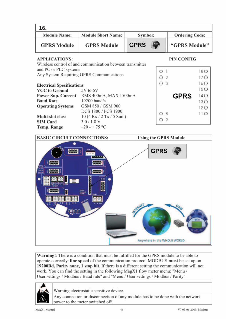
Module Name: Module Short Name: Symbol: Ordering Code:
GPRS Module GPRS Module “GPRS Module”
APPLICATIONS: PIN CONFIG
Wireless control of and communication between transmitter
and PC or PLC systems
Any System Requiring GPRS Communications
Electrical Specifications
VCC to Ground 5V to 6V
Power Sup. Current RMS 400mA, MAX 1500mA
Baud Rate 19200 baud/s
Operating Systems GSM 850 / GSM 900
DCS 1800 / PCS 1900
Multi-slot class 10 (4 Rx / 2 Tx / 5 Sum)
SIM Card 3.0 / 1.8 V
Temp. Range –20 - + 75 °C
BASIC CIRCUIT CONNECTIONS: Using the GPRS Module
Warning electrostatic sensitive device.
Any connection or disconnection of any module has to be done with the network
power to the meter switched off.
Warning!: There is a condition that must be fulfilled for the GPRS module to be able to
operate correctly: line speed of the communication protocol MODBUS must be set up on
19200Bd, Parity none, 1 stop bit. If there is a different setting the communication will not
work. You can find the setting in the following MagX1 flow meter menu: "Menu /
User settings / Modbus / Baud rate" and "Menu / User settings / Modbus / Parity".

MagX1 Manual -47- V7 03-06-2009, Modbus
17. Module positioning.
Individual module installation is straightforward thanks to a plug-and-play system. Yet, some
caution is required when selecting the correct installation slot according to the picture below.
18. Liner and electrode selection.
Liner and electrode material selection are an important issue when choosing your flowmeter. The
tables below serve to give you an idea of general material compatibility. If you are not sure about
suitability of liner/electrode material for a particular medium, please contact the Arkon sales
department for further assistance, and the site where the flowmeter is to be used for what
materials are acceptable for the process media. Arkon can only recommend materials, we cannot
guarantee them.
Liner Selection:
Hard Rubber Drinking water and wastewater 0 - 70°C
Soft Rubber Water with abrasive particles 0 - 70°C
Teflon Chemicals and food industries 0 - 130°C
Electrode selection:
Stainless Steel General purpose, sewage, water
Hastelloy Seawater, Chemicals
Titanium Aggressive chemicals
Platinum Aggressive chemicals

MagX1 Manual -48- V7 03-06-2009, Modbus
19. Flowmeter Dimensions
DN/PN16 A
[mm] D4
[mm] L3
[mm] DN/PN16 A
[mm] D4
[mm] L3
[mm]
10 279 90 200 10 185 90 200
15 284 95 200 15 190 95 200
20 291 105 200 20 197 105 200
25 300 115 200 25 205 115 200
32 315 140 200 32 221 140 200
40 324 150 200 40 230 150 200
50 338 165 200 50 244 165 200
65 358 185 200 65 264 185 200
80 376 200 200 80 282 200 200
100 396 220 250 100 302 220 250
125 424 250 250 125 330 250 250
150 455 285 300 150 361 285 300
200 514 340 350 200 420 340 350
250 586 405 450 250 492 405 450
300 644 460 500 300 550 460 500
350 705 520 543 350 610 520 543
400 760 580 593 400 665 580 593
450 805 615 593 450 710 615 593
500 885 715 593 500 790 715 593
600 1000 840 597 600 908 840 597
Tolerance of built-in length and height for DIN and ANSI type sensors:
DN 10 – DN 150 A/L ± 1 mm
DN 200 – DN 1000 A/L ± 2 mm
Tolerance of inside diameter:
DN 10 – DN 1000 max. 5%.

MagX1 Manual -49- V7 03-06-2009, Modbus
20. How to order your MagX1
In case you are interested in purchasing a MagX1 flowmeter, you can either contact the Arkon
Sales Department and request a quote to serve as a basis for ordering, or you can use the Arkon
price-list as an easy order form. Due to the design of the MagX1, no single ordering code exists;
all modules you would like to add to your order have to be added individually. Only the MagX1
sensor has its own ordering code:
21. MagX1 Error Code Table
Error Code Error Description
000 Empty Pipe! (Air Detect)
001 Memory Module Not Responding
002 RTC Module Not Responding
003 Sensor Not Responding
004 – 008 GPRS Module – communication error
009 GPRS Module – missing SIM card or wrong PIN code
010 GPRS Module – no GSM signal
011 GPRS Module – Dial up error
012 GPRS Module – Unknown IP address
013 - 014 GPRS Module – Online data mode error
Example of an error warning on the MagX1 display:

MagX1 Manual -50- V7 03-06-2009, Modbus
22. Sensor and transmitter versions and compatibility.
It is possible to check the version of each MagX1 in info menu> Firmware No. (see point 3.3).
When changing the communication module, please check the firmware version to know if they
are compatible.
Firmware version also determines if the unit includes automatic electrodes cleaning or
MODBUS communication and if it is compatible with Bluetooth module.
MagX1 offers the option of updating the firmware version using RS232 communication module,
using MagX1 firmware updater software. That is available from Firmware version v.1.12 or
superior.
The following table shows compatibilities between different versions.
FW MB Buttons F-OUT
[Hz]
Sensor
module
UP
Sensor
module
DOWN
Automatic
electrode
cleaning
BlueTooth
module
MODBUS
PC
Power
Supply
FW
update
v.1.05 v.4 mechanical 250 - 10000 v.6 v.6 no no no PS2_4 no
v.1.06 v.4 mechanical 250 - 10000 v.6 v.6 no no no PS2_4 no
v.1.07 v.4 mechanical 250 - 10000 v.6 v.6 no no no PS2_4 no
v.1.10 v.4 mechanical 250 - 10000 v.6 v.6 no no yes PS2_4 no
v.1.11 v.4 mechanical 250 - 10000 v.6 v.6 no no yes PS2_4 no
v.1.12 v.4 mechanical 250 - 10000 v.7 v.6 no no yes PS2_4 yes
v.2.01 v.6 touch 2 - 1000 v.7 v.7 yes yes yes PS2_5,
PS3
yes
v2.02 v.6 touch 2 - 1000 v.7 v.7 yes yes yes PS2_5,
PS3
yes
v2.03 v.6 touch 2 - 1000 v.7 v.7 yes yes yes PS2_5,
PS3
yes
23. CE and Conformity
The MagX1 Electromagnetic flowmeter is manufactured conform CE requirements.
Conformity
requirements
EN 61010-1 : 2003
EN 61000-3-2:2000, A1:2001, A2:2004
EN 61000-3-3:1995, Cor. 1:1997, A1:2001
EN 61326:1997 + A1:1998, cor. 1:1998 + A2:2001 + A3:2001, Table A.1
EN 61326:1997 + A1:1998 + Cor:1998 + A2:2001, + A3:2003, Class A
MagX1 Manual -51- V7 03-06-2009, Modbus
24. Warranty
The warranty conditions are covered by Arkon Flow Systems, s.r.o. Terms & Conditions of Sale
and by Arkon Flow Systems, s.r.o Return Regulations and Warranty Conditions. The Arkon
Flow Systems, s.r.o Terms & Conditions of Sale and the Arkon Flow Systems, s.r.o Return
Regulations and Warranty Conditions are an integral part of the Resellers contract and of any
Order Confirmation. Please see your Resellers contract or www.arkon.co.uk; Support section.
The Warranty sheet is part of the Packing note of any new goods sent. For the claim or return
procedure, please consult our web site www.arkon.co.uk or call the Arkon Flow Systems, s.r.o
sales office.
Contact:
Technical support: [email protected]
Windows life messenger: [email protected]
Office hours:
8:30 – 18:30 (GMT+1)
Direct technical support:
8:00 – 17:00 (GMT+1)

MagX1 Manual -52- V7 03-06-2009, Modbus