magnetic property - mmrc.caltech.edu ac options.pdf · mpms multivu is the software application...
TRANSCRIPT
Ouantum .
e s 1 n ~
Magnetic Property Measurement System
AC Option User's Manual
Part Number 1017-llOA
Quantum Design 11578 Sorrento Valley Rd. San Diego, CA 92121-1311 USA Technical support
Fax
(858) 481-4400 (800) 289-6996 (858) 481-7410
Second edition of manual completed November 1999.
Trademarks All product and company names appearing in this manual are trademarks or registered trademarks of their respective holders.
U.S. Patents 4,791,788 Method for Obtaining Improved Temperature Regulation When Using Liquid Helium Cooling 4,848,093 Apparatus and Method for Regulating Temperature in a Cryogenic Test Chamber 5,053,834 High Symmetry DC Squid System 5, 110, 034 Superconducting Bonds for Thin Film Devices 5, 139, 192 Superconducting Bonds for Thin Film Devices 5,311,125 Magnetic Property Characterization System Employing a Single Sensing Coil Arrangement to Measure AC
Susceptibility and DC Moment of a Sample (patent licensed from Lakeshore) 5,319,307 Geometrically and Electrically Balanced DC Squid System Having a Pair of Intersecting Slits 5,647,228 Apparatus and Method for Regulating Temperature in Cryogenic Test Chamber
Foreign Patents U.K. 9713380.5 Apparatus and Method for Regulating Temperature in Cryogenic Test Chamber Canada 2,089,181 High Symmetry DC Squid System Japan 2,533,428 High Symmetry DC Squid System

C 0 N T E N T S
Table of Contents
PREFACE Contents and Conventions ............................................................................................................................... vii
P.1 Introduction ...................... ~ ................................................................................................................................ vii P .2 Scope of the Manual. ......................................................................................................................................... vii P.3 Contents oftheManual ..................................................................................................................................... vii P .4 Conventions in the Manual .............................................................................................................................. viii
CHAPTERl Introduction to the AC Option ...................................................................................................................... 1-1
1.1 Introduction ...................................................................................................................................................... 1-1 1.2 Overview of the AC Option ............................................................................................................................. 1-1
1.2.1 Advantages of the MPMS AC System ...................................................................................................... 1-1 1.2.2 MeasurementRange .................................................................................................................................. 1-2
1.3 Overview of the AC Option Electronics .......................................................................................................... 1-3 1.3.1 AC Drive System ....................................................................................................................................... 1-3 1.3.2 AC Digitizer .............................................................................................................................................. 1-3
1.4 Overview of System Software .......................................................................................................................... 1-4
CHAPTER2 AC Susceptibility Measurement ................................................................................................................... 2-1
2.1 Introduction ...................................................................................................................................................... 2- l 2.2 Overview of AC Susceptibility Measurements ................................................................................................ 2-1 2.3 Measuring AC Susceptibility ........................................................................................................................... 2-2
2.3.l Attach the Sample ..................................................................................................................................... 2-2 2.3.2 Insert the Sample ....................................................................................................................................... 2-3
2.3.2.1 Vent the Airlock Space ....................................................................................................................... 2-3 2.3.2.2 Lower the Sample Rod into the Airlock Space .................................................................................. 2-4 2 .3 .2 .3 Purge the Airlock Space ..................................................................................................................... 2-5 2.3.2.4 Lower the Sample Rod into the Sample Chamber ............................................................................. 2-5
2.3.3 Confirm the Sample Installation and Define the Sample Parameters ........................................................ 2-6 2.3.4 Center the Sample ..................................................................................................................................... 2-7
2.3.4.1 Initialize the Sample Transport .......................................................................................................... 2-7 2.3.4.2 Define the Parameters ......................................................................................................................... 2-8 2.3.4.3 Run the Centering Measurement ...................................................................................................... 2-10 2.3.4.4 Adjust the Sample Position .............................................................................................................. 2-11
Quantum Design MPMSAC Option User's Jfanual i

Contents Table of Contents
2.3 .5 Measure the Sample ................................................................................................................................ 2-11 2.3.5.1 Define the Parameters ....................................................................................................................... 2-13 2.3 .5 .2 Select the Data Files ........................................................................................................................ .2-14 2.3.5.3 Run the Measurement ....................................................................................................................... 2-15 2.3.5.4 Aborting a Measurement .................................................................................................................. 2-15 2.3.5.5 Viewing the Data Files ..................................................................................................................... 2-15
2.4 Description of the AC Measurement Process ................................................................................................. 2-16 2.5 Description of Signal Nulling ......................................................................................................................... 2-17
2.5 .1 DC Offset Nulling ................................................................................................................................... 2-17 2.5.2 Line Nulling ............................................................................................................................................ 2-l 7 2.5.3 Drive Nulling ........................................................................................................................................... 2-18
CHAPTER3 AC System Calibration .................................................................................................................................... 3-l
3 .1 Introduction ...................................................................................................................................................... 3-1 3 .2 Overview of Calibration .................................................................................................................................. .3-1 3.3 Instrument Response Calibration ..................................................................................................................... 3-1 3.4 Absolute Calibration ........................................................................................................................................ .3-3
CHAPTER4 AC Sequence Commands ............................................................................................................................... .4-l
4 .1 Introduction ..................................................................................................................................................... .4-1 4.2 Description of AC Sequence Commands ......................................................................................................... 4-1
4.2. l AC Center and Measure Sequence Commands ........................................................................................ .4-1 4.2.1.l AC Center .......................................................................................................................................... .4-l 4.2.1.2 AC Parameters ................................................................................................................................... .4-2 4.2.1.3 Measure AC ....................................................................................................................................... .4-2 4.2.1.4 Scan AC Amplitude ............................................................................................................................ 4-3 4.2.1.5 Scan AC Frequency ........................................................................................................................... .4-4
4.2.2 AC Calibration Factor Sequence Commands ........................................................................................... .4-5 4.2.2.1 Current to Flux .................................................................................................................................. .4-5 4.2.2.2 Drive Resolution ................................................................................................................................ .4-5 4.2.2.3 Null Resolution .................................................................................................................................. .4-5 4.2.2.4 Regression ......................................................................................................................................... .4-5
4.2.3 AC Diagnostic Sequence Commands ....................................................................................................... .4-6 4.2.3.1 AC ClockFrequency .......................................................................................................................... 4-6 4.2.3.2 AC Filter ............................................................................................................................................ .4-6 4.2.3.3 Amplifier Gain .................................................................................................................................. .4-6 4.2.3.4 Amplitude .......................................................................................................................................... .4-6 4.2.3.5 Apply Nulling .................................................................................................................................... .4-7 4.2.3.6 Null DC Offset .................................................................................................................................. .4-7 4.2.3. 7 Null Line Noise .................................................................................................................................. 4-7 4.2.3.8 Signal Clocking ................................................................................................................................. .4-7 4.2.3.9 Steps Per Cycle ................................................................................................................................... 4-7 4.2.3.10 Two-Point Measurement ................................................................................................................. .4-7 4.2.3.11 Wave Frequency .............................................................................................................................. .4-7
ii MPMS AC Option User's Manual Quantum Design
CHAPTERS
Contents Table of Contents
AC Calibration Factors and Diagnostics .................................................................................................. 5-1 5.1 Introduction ...................................................................................................................................................... 5-1 5.2 AC Calibration Factors ..................................................................................................................................... 5-1 5.3 AC Diagnostics ................................................................................................................................................ .5-3
5.3.1 AC Diagnostic Settings ............................................................................................................................ .5-4 5.3.1.1 Drive Amplitude ................................................................................................................................. 5-4 5.3.1.2 AC Filter ............................................................................................................................................. 5-4 5.3.1.3 Gain .................................................................................................................................................... 5-4 5.3.1.4 Wave Frequency ................................................................................................................................. 5-5 5.3.1.5 Clock Frequency ................................................................................................................................ 5-5 5.3.1.6 Steps Per Cycle ................................................................................................................................... 5-6 5.3.1.7 Signal Clocking .................................................................................................................................. 5-6 5.3.1.8 Two-Point Measurement .................................................................................................................... 5-6 5.3.1.9 Apply Nulling Waveform ................................................................................................................... 5-6 5.3.1.10 Write Nulling Diag ........................................................................................................................... 5-7
5.3.2 AC Diagnostic Controls ............................................................................................................................ 5-7 5 .3 .2.1 Null DC Offset ................................................................................................................................... 5-7 5.3.2.2 Null Line Noise .................................................................................................................................. 5-7
APPENDIX A Data File Format. ............................................................................................................................................... A-1
A.1 Introduction .................................................................................................................................................... A-1 A.2 Format ofDataFiles ....................................................................................................................................... A-1
A.2.1 Data File Header ...................................................................................................................................... A-1 A.2.2 Data Section ............................................................................................................................................. A-3
A.2.2.1 Data Section Field Names ................................................................................................................ A-3 A.3 Data Types ...................................................................................................................................................... A-4
A.3.1 Numerical Data ........................................................................................................................................ A-4 A.3.2 Strings ...................................................................................................................................................... A-4 A.3.3 Boolean ......................... .-.......................................................................................................................... A-4 A.3.4 Additional Information ............................................................................................................................ A-4
References .............................................................................................................................................. References- I
Index ................................................................................................................................................................. Index-1
Quantum Design MPMS AC Option User's Manual iii

Contents Table of Figures
Figures
Figure 2-1. Positioning the Sample in a Drinking Straw ........................................................................................... 2-2 Figure 2-2. Sample Transport and Electronics Control Assembly ............................................................................ 2-3 Figure 2-3. 0-Rings on Socket Block Assembly ...................................................................................................... 2-4 Figure 2-4. Sample Description Dialog Box ............................................................................................................. 2-6 Figure 2-5. AC Centering Dialog Box ...................................................................................................................... 2-8 Figure 2-6. AC Center Parameters Dialog Box ......................................................................................................... 2-8 Figure 2-7. Plot of AC Centering Scan Data File .................................................................................................... 2-10 Figure 2-8. AC Measurement Dialog Box .............................................................................................................. 2-13
Figure 4-1. Measure AC Dialog Box for Sequence Mode ........................................................................................ 4-2 Figure 4-2. Scan AC Amplitude Dialog Box ........................................................................................................... .4-3 Figure 4-3. Scan AC Frequency Dialog Box ........................................................................................................... .4-4
Figure 5-1. AC Group in Calibration Factors Dialog Box ....................................................................................... .5-2 Figure 5-2. AC Diagnostics Dialog Box .................................................................................................................. .5-3
iv MPMS AC Option User's Manual Quantum Design

Tables
Contents Table of Tables
Table 2-1. Sample Parameters ................................................................................................................................... 2-6 Table 2-2. AC Measurement Parameters ................................................................................................................. 2-12 Tr.ble 2-3. SQUID Parameters ................................................................................................................................. 2-12
Table 5-1. AC Calibration Factors ............................................................................................................................ 5-2 Table 5-2. Clock Frequencies Used to Validate AC Calibration ............................................................................... 5-4 Table 5-3. System-Defined Clock Frequencies ........................................................................................................ .5-5
Quantum Design MPMSACOption User's Manual v


P R E F A C E
Contents and Conventions
P.1
P.2
P.3
Quantum Design
Introduction This preface contains the following information:
• Section P.2 discusses the overall scope of the manual.
• Section P.3 briefly summarizes the contents of the manual.
Scope of the Manual
• Section P.4 illustrates and describes conventions that appear in the manual.
This manual describes the MPMS AC option and explains how to perform AC sample measurements.
MPMS MultiVu is the software application controlling the AC system. The Magnetic Property Measurement System: MPMS MultiVu Application User's Manual discusses MPMS MultiVu in detail.
Contents of the Manual • Chapter I introduces the AC option
and discusses the AC option electronics.
• Chapter 2 explains how to perform an immediate-mode AC measurement.
• Chapter 3 describes the AC system calibration.
• Chapter 4 discusses the AC sequence commands.
• Chapter 5 discusses the AC calibration factors and diagnostics.
• Appendix A discusses the data file format and the information appearing in AC data files.
MPMSACOption User's Manual vii

Section P.4 Conventions in the Manual
Preface Contents and Conventions
P.4 Conventions in the Manual File menu
File>Open
. dat
<Enter>
<Alt+ Enter>
viii
Bold text distinguishes the names of menus, options, buttons, and panels appearing on the PC monitor.
The > symbol indicates that you select multiple, nested software options.
The Courier font distinguishes code and the names of files and directories .
Angle brackets distinguish the names of keys located on the PC keyboard.
A plus sign connecting the names of two or more keys distinguishes keys you press simultaneously.
A pointing hand introduces a supplementary note.
An exclamation point inside an inverted triangle introduces a cautionary note.
A lightning bolt inside an inverted triangle introduces a warning.
MPMS AC Option User's Manual Quantum Design

CHAPTER 1
Introduction to the AC Option
1.1 Introduction This chapter contains the following information:
• Section 1.2 presents an overview of the AC option.
• Section 1.3 presents an overview of the AC electronics.
• Section 1.4 presents an overview of the MPMS MultiVu application.
1.2 Overview of the AC Option
1.2.1
In an AC susceptometer, an oscillating AC magnetic field is applied to the sample. The change in flux seen by the detection circuitry is caused only by the changing magnetic moment of the sample as it responds to the applied AC field. The differential or AC susceptibility ofXac = dM!dH obtained from these measurements is described as having both real and imaginary components X' and X'', where the imaginary component is proportional to the energy losses in the sample. The complex susceptibility can provide various types of information on properties such as the structural details of materials, resonance phenomena, electrical conductivity by induced currents, relaxation processes such as flux profiles and flux creep in superconductors, and energy exchange between magnetic spins and the lattice in paramagnetic materials.
Advantages of the MPMS AC System
Conventional AC susceptometers measure the voltage induced in an inductive detection coil by an oscillating AC magnetic moment. The most common systems use mutual inductance bridges to measure the voltages induced, and some use digital processing to improve noise rejection. These systems measure only signals with frequencies at or very near the applied excitation, so sensitivity is greatly increased by reducing the effective noise level to that in the measurement bandwidth centered on the frequency of interest. However, conventional systems lose sensitivity at low frequencies because the voltage induced in the detection coil is proportional to the frequency of the oscillating drive field.
Quantum Design MPMS AC Option User's Manual 1-1

Section 1.2 Overview of the AC Option
Chapter I Introduction to the AC Option
1.2.2
1-2
The MPMS AC option solves this problem by combining an AC drive field with a SQUID-based detection system. The SQUID (Superconducting QUantum Interference Device) is an extremely sensitive flux-to-voltage converter that directly measures the change in flux as the sample moves through a superconducting detection coil coupled to the SQUID circuit. The frequency-independent coupling between magnetic flux and induced currents in the superconductors allows use of AC frequencies and AC drive fields that are many orders of magnitude lower than those used in conventional AC systems.
In the MPMS AC system, a copper drive coil is used to generate the AC field in the sample chamber. The drive coil is situated in the helium bath between the DC magnet and the gradiometer detection coils, concentric with the MPMS DC superconducting magnet, with all three components combined into a rigid structure to minimize changes in coil geometry as the sample temperature and DC field are varied.
All changes to the MPMS for the AC option are in the Model 1822 MPMS Controller electronics and the accompanying software. All operations necessary for taking AC measurements are integrated into the MPMS MultiVu software application. The MPMS AC system automatically controls operations during a measurement; user input is required only to initiate the measurement.
Measurement Range
The MPMS AC system allows AC measurements of a sample's magnetic moment with a resolution of 5 x 10· 12 A · m2 over a frequency range of 0.001-1000 Hz with loss of sensitivity occurring only at frequencies below 0.01 Hz. The MPMS AC system operates over the temperature range of2-400 K and in applied DC fields up to ±7 T. The system's combination of extremely high SQUID sensitivity and the inherently high noise rejection in AC techniques offers the potential for extremely sensitive AC susceptibility measurements on spin glasses and on other samples characterized by long relaxation times. The MPMS AC system is also ideal for samples, such as high-temperature superconductors, whose material characteristics or magnetic effects require very small excitation fields.
MPMSAC Option User's Manual Quantum Design

Chapter 1 Introduction to the AC Option
Section 1.3 Overview C?fthe AC Option Electronics
1.3 Overview of the AC Option Electronics
1.3.1
1.3.2
In the MPMS AC system, magnetic flux from the sample is detected by a superconducting pickup coil that is part of a closed-loop superconducting circuit inductively coupled to the SQUID. The feedback circuitry is also coupled to this circuit through a superconducting DC flux transformer. The voltage output from the SQUID electronics, which is proportional to the flux change in the detection coils, is digitized by the AC digitizer and recorded in a data file. A current, proportional to the signal voltage, is created by the AC drive system. This current, along with other noise-canceling signals, can be fed back inductively to the superconducting input circuit through the feedback flux transformer.
The master timing signal for the MPMS AC system is a 12-MHz crystal oscillator. This 12-MHz crystal oscillator is reduced to 6 MHz to drive the analog-to-digital (AID) converter for the AC digitizer, and is reduced again to 3 MHz before being passed to the AC drive system.
AC Drive System
The AC drive system contains a ripple counter that reduces the incoming 3-MHz signal into five clock rates between 187.5 kHz and 2.861 Hz. The clock rates drive two 16-bit waveform synthesizers. One synthesizer drives the solenoid that creates the AC field, and the other nulls both the sample signal and the drive signal that couples to the SQUID via the gradiometer imbalance.
The synthesizers are based on a memory chip organized as an FIFO (First In, First Out) buffer. The outputs of the FIFO are connected to a digital-to-analog (DAC) converter where the analog waveforms are generated and sent to the appropriate coils. Both channels contain differential amplifiers, with ranges ofxl and xlOO, that are switched simultaneously to give an effective resolution of23 bits.
The channels are clocked synchronously and contain the same number of points----up to a maximum of 8192 points--per output sine wave. To keep harmonics to an acceptable level, the system uses a minimum of 124 digital points for sine wave generation. When phase shifts are required between the output of the drive and nulling channels, they are produced by numerically offsetting the digital sine waves loaded into the FIFOs.
AC Digitizer
The primary component of the AC digitizer is a 12-bit AID converter that digitally samples the voltage output of the SQUID electronics synchronous to the drive waveform synthesizer. Before being digitized, the signal is passed through an instrumentation amplifier with gains of x l, x 10, and x 100, in addition to the range and gain settings of the SQUID electronics. The selectable 60-Hz notch filters provide anti-aliasing and noise reduction. The filter roll-off frequencies were chosen to give small phase shifts ofless than 3° at the maximum-intended drive :frequency for each sampling rate.
The data is stored in on-board memory and passed to a data file at the end of a measurement. The maximum number of wave periods digitized in a given measurement is determined by the size of the digitizer memory. A maximum of 65,535 16-bit data points can be stored on the board, thus limiting the maximum amount of averaging that can be used per measurement. Data, recorded in blocks of two wave periods, is transferred to the host computer. The MPMS MultiVu application adds the data from different blocks together point by point. This procedure has the effect of averaging the background noise at a given data point. The amplitude and phase of the resulting two-cycle data set are calculated by using a regression algorithm with the known frequency as a fixed parameter. The calibrated phase and amplitude corrections are applied to the raw data, and the in-phase and out-of-phase sample moments can be recorded in several data files.
Quantum Design MPMSAC Option User's Manual 1-3

Section 1.4 Overview of System Software
Chapter 1 Introduction to the AC Option
1.4 Overview of System Software
1-4
The MPMS MultiVu software application controls and monitors the operation of the MPMS hardware and the AC option. You select all AC commands in the MPMS MultiVu interface. Consequently, while you work with the AC option, you can use any MPMS MultiVu function. For example, before running an AC measurement, you can set the field or temperature, and when the measurement is complete, you can use multiple data-viewing formats to examine the data.
MPMS MultiVu supports manual, or immediate, tasks and automated, or sequence, tasks. You automate tasks by running a sequence. The Magnetic Property Measurement System: MPMS MultiVu Application User's Manual discusses sequences in detail.
AC data files and DC data files contain the identical header information but document different types of data field information. Appendix A discusses the data file format in detail.
MPMS AC Option User's Manual Quantum Design

CHAPTER 2
AC Susceptibility Measurement
2.1 Introduction This chapter contains the following information:
• Section 2.2 presents an overview of AC susceptibility measurements.
• Section 2.3 explains how to perform an immediate-mode AC susceptibility measurement.
• Section 2.4 describes the measurement process.
• Section 2.5 describes the signal-nulling functions.
2.2 Overview of AC Susceptibility Measurements A standard measurement of the AC susceptibility of a sample is a two-point measurement that positions the sample in two locations within the SQUID pickup coils and, at each location, measures the effect of a nulling waveform on the sample's magnetic moment. This two-point measurement nulls all spurious signals at the AC measurement frequency and allows extremely accurate measurements of the sample's AC susceptibility.
For the first part of the two-point measurement, the sample is positioned in the center of the bottom SQUID pickup coil. For the second part of the two-point measurement, the sample is positioned in the center of the two middle pickup coils. During both measurements, the MPMS AC system sends a nulling waveform through the SQUID circuitry. When the sample is in the positively oriented, bottom pickup coil, the nulling waveform is generated so that it cancels all signals, including the sample signal. When the sample is in the two middle, negatively oriented coils, the negative polarity of the nulling waveform is identical to the polarity of the coils, so the strength of the sample signal is increased three-fold. This increased sample signal is the signal the system measures to determine the AC susceptibility.
Quantum Design MPMS AC Option User's Manual 2-1

Section 2.3 Measuring AC Susceptibility
Chapter2 AC Susceptibility Measurement
2.3 Measuring AC Susceptibility
2.3.1
2-2
This section explains how you perform a manual, or immediate, AC measurement. The Magnetic Property Measurement System: MPMS MultiVu Application User's Manual explains how you automate measurements by running a sequence. Chapter 4 in this manual discusses the AC sequence commands.
You can use the standard sample transport or the RSO sample transport to perform AC measurements. This section explains how you use the standard transport. The Magnetic Property Measurement System: Reciprocating Sample Option User's Manual explains how you use the RSO transport.
Attach the Sample
The type, size, and geometry of a sample determine the method you use to attach it to the sample rod. This section explains how you use a clear plastic drinking straw to attach a sample. The straw has minimal magnetic susceptibility and is thus a useful means of attaching a sample. The MPMS Hardware Reference Manual describes other techniques you can use to attach a sample.
The susceptibility of the small straw segment used to hold the sample in the following procedure is approximately 9 x 10⁻⁹ EMU in a temperature range of 100-300 K. Notice that a clear plastic straw creates a significant background moment if the sample has an extremely small moment. Colored drinking straws, which can have dyes with considerable magnetic susceptibility, should never be used to attach samples to the sample rod. Clear plastic drinking straws are available from Quantum Design.
Complete the following steps to attach the sample to the sample rod:
1. Cut off an approximately 5-mm-long section of a clear plastic drinking straw. The cut-off section, which is called the straw segment, must be small enough to fit inside another straw when the two open ends of the segment are held vertically.
2. Weigh and measure the sample. After you inse1: the sample into the sample chamber, you can use the Sample Description dialog box to specify the mass, diameter, and length of the sample so that these values are saved to a data file header.
3. Place the sample inside the straw segment. Quantum Design recommends using phenolic tweezers to pick up and hold the sample. You can use a small amount of Apiezon M Grease to prevent the sample from shaking or rattling inside the straw segment.
4. Hold the straw segment so that its two open ends are vertical.
5. Place the straw segment inside another clear
SAMPLE
•\'@ STRAW SEGMENT
/
plastic drinking straw. Move the segment Figure 2-1. Positioning the Sample in a until it is in approximately the middle of the Drinking Straw length of the straw. Verify that the walls of the straw obstruct the open ends of the segment and that the sample and segment are securely positioned. The sample must not slip or rattle when you shake the straw.
6. Wrap tape around the brass-colored end of the sample rod. Use enough tape so that the drinking straw will fit snugly over the rod. Quantum Design recommends using Kapton tape.
7. Place the end of the drinking straw over the tape on the sample rod. Use additional tape to securely attach the straw to the rod.
MPMS AC Option User's Manual Quantum Design

Chapter 2 AC Susceptibility Measurement
Section 2.3 Measuring AC Susceptibility
2.3.2
Quantum Design
8. Place a small piece of tape over the exposed end of the drinking straw. This extra piece of tape prevents a loose sample from falling into the sample chamber.
9. Move the slide seal plug up and down part of the sample rod to verify that the rod is well lubricated. If the plug does not move easily, apply a small amount of Apiezon H Grease to the rod. Run your fingers along the length of the rod to ensure a light, even coating of grease.
Insert the Sample
2.3.2.1 VENT THE AIRLOCK SPACE
1. Tum the airlock lever on the front of the probe's electronics control assembly (figure 2-2) counterclockwise until it is horizontal and in the "Closed" position.
When the airlock lever is in the "Closed" position, it closes the airlock value and thus isolates the lower portion of the sample chamber, protecting it from air flowing into the top portion of the chamber. The top portion of the chamber is called the airlock space. The MPMS vents the airlock space when the airlock valve is closed.
AIRLOCK PLUG
SOCKET BLOCK ASSEMBLY
AIRLOCK SPACE VIEW-PORT
READY LED
VENTING LED
SLIDE SEAL CLAMPS
AIRLOCK LEVER
Figure 2-2. Sample Transport and Electronics Control Assembly
MPMS AC Option User's Manual 2-3

Section 2.3 Measuring AC Susceptibility
Chapter2 AC Susceptibility Measurement
WARNING
2-4
2. Wait for the MPMS to vent the airlock space. The yellow "Venting" LED flashes on and off while the MPMS vents the space and then remains off when the space is vented. The green "Ready" LED does not tum on.
3. Push the two slide seal clamps so that the clamp handles face the front of the MPMS. The slide seal clamps are on the socket block assembly (see figures 2-2 and 2-3). When the clamp handles face the front of the MPMS, the airlock plug is unlocked and may be removed from the opening of the airlock space.
4. Remove the airlock plug, which has an anodized, blue coating. Store the plug in a safe place.
2.3.2.2 LOWER THE SAMPLE ROD INTO THE AIRLOCK SPACE
I. Verify that three 0-rings are on top of the socket block assembly. Refer to figure 2-3 below. If necessary, stand on a stool or small ladder to examine the top of the socket block. The large 0-ring at the mouth of the airlock space occasionally sticks to the sample rod when the rod is removed from the sample chamber. Reinsert any missing 0-rings.
Never insert the sample rod into the sample chamber ifthe 0-rings on top of the socket block assembly are missing. The 0-rings prevent air, which can damage the vacuum pump and freeze the sample, from pumping into the chamber.
0-RING (VON2-006)
0-RING (VON2-015)
0-RING (VON2-006)
SLIDE SEAL CLAMP
Figure 2-3. 0-Rings on Socket Block Assembly
2. Move the slide seal plug down the sample rod until the plug rests just above the sample holder.
3. Lower the sample rod into the airlock space. Look at the view port on the front of the sample transport. You should see the sample rod.
4. Move the slide seal plug down the sample rod i.ntil the plug rests on top of the socket block assembly. If necessary, adjust the position of the slide seal clamps in order to correctly seat the plug.
5. Tum the slide seal plug until the white dot on the plug faces the front of the MPMS. When the white dot faces the front of the MPMS, the proper amount of gas flows through the slide seal.
6. Push the two slide seal clamps completely outward or inward. When the handles of the clamps do not face the front of the MPMS, the clamps lock the slide seal plug in position by forcing it downward against the three 0-rings.
MPMS AC Option User's Manual Quantum Design

Chapter 2 Section 2.3 AC Susceptibility Measurement Measuring AC Susceptibility
2.3.2.3 PURGE THE AIRLOCK SPACE
1. Press the "Purge Airlock" button. The button if on the front of the probe's electronics control assembly. When you push the button, the MPMS purges the airlock space. The MPMS cycles through the purge sequence four times. The yellow "Venting" LED turns on during the purge.
2. Wait for the MPMS to purge the airlock space. The green "Ready" LED turns on when the purge is complete.
If the "Ready" LED does not tum on, the airlock space may have a leak. Missing or improperly seated 0-rings may cause the leak. Perform the following steps to check for a leak: (1) Select lnstrument>Chamber>Vent Sample Space to vent the sample chamber; (2) remove the sample rod when the "Venting" LED turns off; and (3) verify that the 0-rings are properly seated and lubricated. If necessary, correctly seat and lubricate the 0-rings.
2.3.2.4 LOWER THE SAMPLE ROD INTO THE SAMPLE CHAMBER
1. Tum the airlock lever clockwise until it is vertical and in the "Open" position. When the lever is in the "Open" position, it opens the airlock value.
2. Lower the sample rod gently and slowly until the black slide clamp engages the actuator shoe on top of the sample transport (see figure 2-2). The rod is now fully inserted in the sample chamber.
The knurled nut must be near the top of the sample rod or you will be unable to fully insert the rod. If necessary, loosen the nut, and then move it until it is 1-2 inches from the top of the rod.
3. Loosen the two clip screws until the screw threads are visible. The clip screws are on top of the actuator shoe. Do not remove the screws.
4. Rotate the slide clamp so that its two curved slots hook around the clip screws. If necessary, continue to loosen the clip screws until the slide clamp is properly seated.
5. Tighten the clip screws. The clip screws secure the sample rod to the actuator shoe, so the sample transport can move the rod vertically.
Quantum Design MPMSAC Option User's Manual 2-5

Section 2.3 Measuring AC Susceptibility
Chapter 2 AC Susceptibility Measurement
2.3.3
w NOTE
2-6
Confirm the Sample Installation and Derme the Sample Parameters
1. Select Sample> Description if the Sample Description dialog box is not open.
Sample Desc11ption EJ - 1
Figure 2-4. Sample Description Dialog Box
2.
3.
Verify that the Sample Installed check box is selected. If necessary, click on the check box.
Define the sample parameters if you want to save them to a new measurement data, or . dat, file. Defining the sample parameters is optional. Do the following to define the parameters:
MPMS MultiVu does not read the sample parameters during the measurement. However, if you want to save the parameters to a new . da t file, you must define them before you specify the base name of the . da t file and before you run the measurement. MPMS MultiVu saves sample parameter data to a data file header only while creating the . da t file.
(a) Enter a descriptive name for the sample. Table 2-1. Sample Parameters This is the name under which MPMS MultiVu stores all information about the sample and the measurement.
(b) Enter the sample mass, in milligrams.
( c) Enter the sample diameter, in millimeters.
( d) Enter the sample length, in millimeters.
( e) Define the sample shape, if necessary.
(f) Enter a comment in order to include a comment in the data file header. A comment may have up to 63 characters.
PARAMETER
Mass
Diameter
Length
4. Select OK. The Sample Description dialog box closes.
MPMS AC Option User's Manual
ACCEPTED DEFAULT VALUES VALUE
0-10,000 mg 1 mg
0-9mm Imm
0-lOOmm Imm
Quantum Design

Chapter 2 AC Susceptibility Measurement
Section 2.3 Measuring AC Susceptibility
2.3.4
w NOTE
w NOTE
Quantum Design
Center the Sample
The sample must be centered in the SQUID pickup coils to ensure that it is correctly positioned within the bottom and middle pickup coils during the subsequent AC measurement. The sample is centered when it is within 0.05 cm of the half-way point of the system-defined, 6-cm scan length.
You may use an AC centering measurement or a DC centering measurement to center the sample. The procedures below explain how you run an AC center.:Ug measurement. AC centering more accurately centers the sample in preparation for AC sample measurements. AC centering also works best with hysteretic samples because it does not require a DC field in the magnet. However, AC centering ta1ces considerably longer to complete than DC centering, and DC centering works best with samples having strong magnetic moments an AC field cannot affect. The Magnetic Property Measurement System: MPMS MultiVu Application User's Manual explains how you run a DC centering measurement.
If you use DC centering to center the sample for AC sample measurements, specify a scan length of 6 cm and enable autoranging and autotracking. You should also verify that a DC field is in the magnet.
MPMS MultiVu automatically saves AC centering measurement data to the center. ac. lasts can file. The Magnetic Property Measurement System: MPMS MultiVu Application User's Manual discusses data files and data-viewing formats in detail.
2.3.4.1 INITIALIZE THE SAMPLE TRANSPORT
The transport must be initialized before an AC centering measurement is ta1cen. The system-defined, 6-cm distance of the AC centering scan moves the transport through the bottom and middle SQUID pickup coils only if the transport is in the initialization position when centering begins. Movement through the bottom and middle coils is necessary to center the sample.
1. Select Center>AC. The AC Centering dialog box opens (see figure 2-5 on the following page). The Status panel at the top of the dialog box indicates both the current AC measurement status and the EMU range and center position from the last AC measurement. The Control panel contains the centering command buttons. The function of each button is summarized to the right of the button.
The magnetic moment is not applicable during an AC centering measurement because the centering measurement calculates a relative amplitude, not a DC moment.
2. Select Initialize Transport. The MPMS initializes, or calibrates, the sample transport by first lowering it to the lower-travel-limit switch, which is defined as zero, and then raising it until it is in a known position that is just above the limit switch. When the transport is in this known position, it is correctly located to begin centering the sample.
If autotracking is enabled when you initialize the transport, the MPMS moves the transport to a position that is far enough above the lower-travel-limit switch in order to allow adjustments for any shrinkage occurring in the sample rod. This position corresponds to a 0.5-cm offset when the sample chamber is at room temperature. To enable or disable autotracking, select Center> AC> Parameters> Autotracking. Refer to section 2.3.4.2 below.
MPMS AC Option User's Manual 2-7

Section 2.3 Measuring AC Susceptibility
Chapter 2 AC Susceptibility Measurement
2-8
2.3.4.2
AC Centering l!!liil EJ .Statu$-·-. -. "'c:....:.,·~-~-~--~-,..,,,.,
]MeasurementJ~e,
.·:·-.. _· .. _-;;-
Moment I NIA , EMU
~~ In 0.000125 ~n
-lfi~@:!i~eg~1J ~rate aie'ia~~leuan~t _
Parameters ..... f-befin , wan ~~er~. · ·F·,·.11.•.".·.r;·'"· ·~~ ·----1·.---·_sci.i.f\the entir_e_le!\lllh ___ ·-__ -_-_-. -__ ·.or··. -' .. v·-· "'··~·• ; 1ran*l)Ort travel - -_ :··-- -' ,
- .&e;ter I Pedorm .~nle!~ SC<n
-M~stPo~lti()n .. ~ J :e:~f:t~:JJD~~~ ~~~~----~--------~
Figure 2-5. AC Centering Dialog Box
DEFINE THE PARAMETERS
I. Select Parameters in the AC Centering dialog box. The AC Center Parameters dialog box opens. The dialog box lists the AC parameters and SQUID parameters the MPMS AC system uses during an AC centering measurement. Tables 2-2 and 2-3 define the AC and SQUID parameters, respectively.
All parameters used during an AC centering measurement are used for the subsequent AC sample measurement unless new values are specified prior to running the measurement.
AC Center Parameters EJ •,...-Acf>~rameteti•.- ... - __ -- . -- .. .. --- - - - - - - , 1 l D~Am~ude lilj •. .· 'a;~stQA;~,agll fr __ H f
W'av~ Frequenc~ J §99:627 ..• · - 'Time~ _Av,erage fi·QAA9 . ~~~j 4 Ar@filierliam.!x1,_ .. s:J P' AtiiqTrack~· . I i - NuUAmpfitud!i j1_ e-006 . EMU r• APl>fyNl.liing;W'avefonn J -r~-- _. _-_:_:_:__ __ .c......::_:::..::.:_ __ • ___ ;._...:;_---------=~:..:.-~Jf~-~!ierin_g'~J::_: _,_: ___ r
Figure 2-6. AC Center Parameters Dialog Box
2. Define the amplitude, in oersted, of the AC drive signal the MPMS AC system applies to the sample. The drive amplitude may be any value from 0.0001 to 5.21893 Oe. The effective 23-bit nature of the system allows a resolution sufficiently fine that only a negligible difference exists between the amplitude you specify and the amplitude the system uses.
3. Defme the frequency, in hertz, of the AC drive signal the system applies to the sample. The wave frequency may be any value from 0. 0003 5 to 1512. I Hz, although the system is calibrated from only 0.01 to 1000 Hz.
The wave frequency is a function of the clock frequency and the steps-per-cycle diagnostic parameters. Both these parameters must have discrete values. Consequently, the wave frequency the system uses may vary slightly from the wave frequency you specify. The system sets and uses the nearest available wave frequency.
MPMSACOption User's Manual Quantum Design

Chapter2 AC Susceptibility Measurement
Section 2.3 Measuring AC Susceptibility
w NOTE
w NOTE
Quantum Design
4.
5.
6.
7.
8.
9.
Select the amplifier gain the system uses to control the gain of the input amplifier that is on the AC digitizer card. The system uses the amplifi.~r gain you select only if autoranging is disabled. If autoranging is enabled, the system automatically adjusts the gain whenever DC offset nulling, line nulling, or an AC measurement is performed. To enable or disable autoranging, select Center> AC> Parameters> Use Autoranging. Refer to step 10.
Define the maximum amplitude of the waveform the system uses to null the AC drive signal. The magnitude of the AC drive signal determines the optimum choice for the null amplitude.
Specify the number of data blocks MPMS MultiVu averages together for one measurement. Each data block contains two complete cycles, or sine waves, of data. The maximum number of blocks is 264 unless the memory available to store data points limits the number to some other value. The memory available to store data points is defined by Max Blocks= 2/S, where Sis the number of steps per cycle.
Verify that autotracking is enabled. If necessary, click once on the Autotracking check box. Autotracking compensates for thermal expansion and contraction in the sample rod.
Disable autotracking only if you are working with a sample that is very sensitive to centering or if you are using a custom-built sample rod. Autotracking instructs the MPMS to track and, before each measurement, to adjust the position of the sample in order to keep the sample centered in the pickup coils.
Enable drive nulling if you want to null the AC drive signal during the centering measurement. Quantum Design recommends that drive nulling be disabled during centering measurements, because centering measurements do not require the high accuracy nulling allows. Drive nulling ensures very accurate measurements, but considerably lengthens the centering process.
The Apply Nulling Waveform check box enables or disables drive nulling only during centering measurements. By default, drive nulling is enabled during sample measurements and disabled during AC centering scans.
Define the length, in seconds, of the SQUID settling time. The SQUID settling time is the time required, immediately after the sample moves, to allow the SQUID electronics to settle so that they stop reading the disruption created by the sample's movement. Longer settling times are necessary when the DC field is large.
10. Verify that autoranging is enabled. If necessary, click once on the Use Autoranging check box. Autoranging allows MPMS MultiVu to change the EMU range as necessary so that the EMU range is appropriate for the SQUID output. The EMU range is a sensitivity value that indicates the maximum magnetic moment the system can measure without saturating the SQUID detector.
The MPMS AC system can optimize the SQUID sensitivity for drive nulling only if autoranging is enabled. If the system will null the AC drive signal during the centering measurement, autoranging must be enabled.
11. Select OK. The AC Center Parameters dialog box closes.
MPMS AC Option User's Manual 2-9

Section2.3 Measuring AC Susceptibility
Chapter 2 AC Susceptibility Measurement
2-10
2.3.4.3 RUN THE CENTERING MEASUREMENT
1. Select Center in the AC Centering dialog box. The centering measurement begins. MPMS MultiVu takes 41 measurements of the absolute magnitude of the sample's response to the AC drive signal. The measurements are evenly spaced over a fixed distance of 6 cm. MPMS MultiVu takes the first measurement while the sample transport is in the initialization position. Then as the transport moves upward, MPMS MultiVu takes 40 additional measurements. If drive nulling is enabled, the system nulls only the fir~t measurement. Status messages at the top of the AC Centering dialog box identify each task the system performs.
MPMS MultiVu saves all data from the centering measurement to the centering scan data, or center. ac. last scan, file. When the centering measurement is complete, the file opens as a graph that plots the SQUID's voltage response against the length of the scan (see figure 2-7).
As soon as the centering measurement is complete, the AC Centering dialog box displays the new center position.
You may abort an AC centering measurement at any time by selecting the Abort button that is at the bottom of the AC Centering dialog box.
2. Examine the plot of the center. ac. lasts can file to determine whether the sample is centered in the SQUID pickup coils. The sample is centered when the peak of the large, middle curve is within 0.05 cm of the half-way point of the scan length. In the 6-cm AC centering scan, the sample is centered when the peak of the middle curve is within 0.05 cm of the 3-cm point.
The shape of the plot is a function of the geometry of the pickup coils. The coils are wound in a second-derivative configuration in which the single-tum, positively oriented top and bottom coils are counterwound with respect to the two-tum, negatively oriented center coil. In the plot of the center. ac. lastscan file, the large, middle curve is the reading from the two center coils. The smaller curve is the reading from the first coil. The response is similar to the response curve from a DC centering measurement.
.Graph View - center_ac.lastscan 1!!11~~
_··i
i----t---t---+-tt---it----t----i---i I
7
.. R>8~n(onj •
Figure 2-7. Plot of AC Centering Scan Data File
MPMSACOption User's Manual Quantum Design

Chapter 2 Section 2.3 AC Susceptibility Measurement Measuring AC Susceptibility
2.3.5
CAUTION
2.3.4.4 ADJUST THE SAMPLE POSITION
1. Select Adjust Position in the AC Centering dialog box only if the sample is not centered in the SQUID pickup coils. The Adjust Sample Position dialog box opens.
2. Specify the correct position of the sample if the computed position displayed in the Sample Location text box is incorrect.
3. Verify that the Perform scan after adjustment check box is selected. If necessary, click once on the check box.
4. Select Adjust Automatically. The MPMS adjusts the position of the sample so that the center peak of the SQUID's voltage response is within 0.05 cm of the half-way point of the scan length. An AC centering measurement then runs. A plot of the center. ac. last scan file opens when the centering measurement is complete.
If automatic adjustment is outside the limits of the transport mechanism and the RSO option is not installed, you must manually adjust the sample position. Select Adjust Manually in the Adjust Sample Position dialog box, and then follow the on-screen instructions.
• Lower the sample ifthe peak of the large, middle curve in the center. ac. lastscan file is to the left of the half-way point of the scan length.
• Raise the sample ifthe peak of the large, middle curve in the center. ac. lastscan file is to the right of the half-way point of the scan length.
5. Select Close twice.
Measure the Sample
When you initiate an immediate-mode measurement, MPMS MultiVu measures the sample at the current system conditions and does not wait for conditions to stabilize. If you want system conditions to be stable when the measurement begins, you run the measurement in a sequence and use appropriate sequence commands to stabilize system conditions. The Magnetic Property Measurement System: MPMS MultiVu Application User's Manual explains how you run a sequence.
You may take a two-point or a one-point AC sample measurement. The two-point measurement is the default, and the procedures below explain how you perform a two-point measurement. A one-point measurement is faster, but less accurate. To enable one-point measurements, you select Utilities> Diagnostics> AC and disable the Two Point Measurement check box.
By default, drive nulling is always enabled during AC sample measurements. Drive nulling allows the MPMS AC system to accurately measure the AC susceptibility of the sample. If drive nullinf is disabled, you must enable it prior to running the measurement. Select Utilities> Diagnostics> AC and enable the Apply Nulling Waveform check box.
Up to four different data files store the data generated during a sample measurement. MPMS MultiVu automatically saves measurement data to a data, or . dat, file and a scan data, or . last scan, file. MPMS MultiVu also saves data to a diagnostic data, or . diag, file and a raw data, or . raw, file if it is instructed to do so. Every data file storing AC measurement data or created to store AC measurement data has a . ac file extension. The Magnetic Property Measurement System: MPMS MultiVu Application User's Manual discusses data files and data-viewing formats in detail.
Table 2-2 defines the AC measurement parameters. Table 2-3 defines the SQUID parameters.
Quantum Design MPMS AC Option User's Manual 2-11

Section2.3 Measuring AC Susceptibility
Table 2-2. AC Measurement Parameters
PARAMETER DEFINITION
Drive Amplitude Amplitude of applied AC drive signal.
Wave Frequency Frequency of applied AC drive signal.
Amplifier Gain Gain of input amplifier located on AC digitizer card. User selection affects operation only if autoranging is disabled.
Null Amplitude Maximum amplitude of drive-nulling signal.
Blocks to Average Number of data blocks averaged together.
Meas. to Average Number of measurements averaged together.
Time to Average Length of time required to collect data. Time to average is determined by wave frequency and number of blocks to average.
Autotracking Automatic adjustment of sample's position to keep sample centered in pickup coils.
Table 2-3. SQUID Parameters
PARAMETER DEFINITION
Settling Time Time required to allow SQUID electronics to settle after sample has moved.
Auto ranging Maximum magnetic moment system can measure without saturating SQUID detector.
Chapter 2 AC Susceptibility Measurement
VALUES
0.0001-5.2189 Oe
0.00035-1512.1 Hz
xl xlO xlOO
(Variable) EMU
1-255
1-100
(Variable) sec.
Enabled Disabled
VALUES
0-32400 sec.
Enabled Disabled
Sections 2.3.5.1 through 2.3.5.3 summarize the steps you complete to run an AC measurement.
2-12 MPMS AC Option User's Manual Quantum Design

Chapter2 AC Susceptibility Measurement
Section 2.3 Measuring AC Susceptibility
Quantum Design
2.3.5.1 DEFINE THE PARAMETERS
1. Select Measure> AC. The AC Measurement dialog box opens. The Status panel at the top of the dialog box indicates both the current AC measurement status and the magnetic moment and standard deviation from the last AC measurement. The Control panel lists the parameters the MPMS AC system uses during a sample measurement and identifies which data files will store the measurement data.
AC Measurement llll!Hil £1 'r. Status ·. ... . . . .... . . . •. . . .
:1 •· itie~inent td~T7 .· .. ·.·. < ir-d ~ .. -•.•. ~ ••• ~ .••• ~ ... -.. -~ .. _., •• -••• -. ~ ..•. ~ ..
ii ~ude~ ~; i 2.~.I)~· . StdDev rofiloooor+o\xr . '! Ph~ •c m" j•2.777S3()ft1l0t StdD~v : 11:oom+oori .j
~~~1t~i~fi~11 f;:c~QUID Par ers; . . . . . .i]
!1~~;r~1 ·i.1'----::=~-...:...:..::...·....:::...::.:::::...._:.:_ ___ ~.::.~~----~: ____ .:;:::..=::.::...:::..-:...:...: •• ~-:...:i-
Figure 2-8. AC Measurement Dialog Box
2. Select the coordinate system MPMS MultiVu uses to display the measurement data. Data may be displayed in the amplitude and phase coordinate system or the m' and m" (in-phase and quadrature) coordinate system.
3. Define the amplitude, in oersted, of the AC drive signal the MPMS AC system applies to the sample. The drive amplitude may be any value from 0.0001 to 5.21893 Oe. The effective 23-bit nature of the system allows a resolution sufficiently fine that only a negligible difference exists between the amplitude you specify and the am:i:litude the system uses.
4. Define the frequency, in hertz, of the AC drive signal the system applies to the sample. The wave frequency may be any value from 0.00035 to 1512.1 Hz, although the system is calibrated from only 0.01 to 1000 Hz.
The wave frequency is a function of the clock frequency and the steps-per-cycle diagnostic parameters. Both these parameters must have discrete values. Consequently, the wave frequency the system uses may vary slightly from the wave frequency you specify. The system sets and uses the nearest available wave frequency.
5. Select the amplifier gain the system uses to control the gain of the input amplifier that is on the AC digitizer card. The system uses the amplifier gain you select only if autoranging is disabled. If autoranging is enabled, the system automatically adjusts the gain whenever DC offset nulling, line nulling, or an AC measurement is performed.
6. Define the maximum amplitude of the waveform the system uses to null the AC drive signal. The magnitude of the AC drive signal determines the optimum choice for the null amplitude.
MPMS AC Option User's Manual 2-13

Section 2.3 Measuring AC Susceptibility
Chapter2 AC Susceptibility Measurement
1(§ NOTE
1(§ NOTE
2-14
7. Specify the number of data blocks MPMS MultiVu averages together for one measurement. Each data block contains two complete cycles, or sine waves, of data. The maximum number of blocks is 264 unless the memory available to store data points limits the number to some other value. The memory available to store data points is defined by Max Blocks= 2/S, where Sis the number of steps per cycle.
8. Specify the number of individual, two-point measurements MPMS MultiVu averages together to compute a final measurement value. MPMS MultiVu may average together up to 100 two-point measurements.
9. Verify that autotracking is enabled. If necessary, click once on the Autotracking check box. Autotracking compensates for thermal expansion and contraction in the sample rod.
Disable autotracking only if you are working with a sample that is very sensitive to centering or if you are using a custom-built sample rod. Autotracking instructs the MPMS to track and, before each measurement, to adjust the position of the sample in order to keep the sample centered in the pickup coils.
10. Define the length, in seconds, of the SQUID settling time. The SQUID settling time is the time required, immediately after the sample moves, to allow the SQUID electronics to settle so that they stop reading the disruption created by the sample's movement. Longer settling times are necessary when the DC field is large.
11. Verify that autoranging is enabled. If necessary, click once on the Use Autoranging check box. Autoranging allows MPMS MultiVu to change the EMU range as necessary so that the EMU range is appropriate for the SQUID output. The EMU range is a sensitivity value that indicates the maximum magnetic moment the system can measure without saturating the SQUID detector.
The MPMS AC system can optimize the SQUID sensitivity for drive nulling only if autoranging is enabled. If the system will null the AC drive signal during the centering measurement, autoranging must be enabled.
2.3.5.2 SELECT THE DATA FILES
1. Select Change in the AC Measurement dialog box if you want to save measurement data to a file other than the measurement data, or . da t, file currently selected to store immediate-mode measurement data. The name of the selected . da t file appears in the Data File panel, which is to the left of the Change button.
Change opens the Select or Enter a New AC Data File dialog box. You can select a file and then select Open, or you can enter the base name of a file in the File name text box, and then select Open.
You must create a new . da t file if you want to save the sample parameter data you entered in section 2.3.3 to a . dat file. MPMS MultiVu saves sample parameter data to a data file header only while creating the . dat file. Consequently, there may not be an existing data file containing sample parameter data identifying your sample. If you want to append data to an existing . da t file, try to select a file whose header information identifies your sample.
2. Verify that the Include Diagnostic Data check box is selected if you want to save diagnostic measurement data to a diagnostic data file. If necessary, click once on the check box.
3. Verify that the Include Raw Data check box is selected if you want to save raw measurement data to a raw data file. If necessary, click once on the check box.
MPMS AC Option User's Manual Quantum Design

Chapter 2 Section 2.3 AC Susceptibility Measurement Measuring AC Susceptibility
Quantum Design
2.3.5.3 RUN THE MEASUREMENT
To run the measurement, select Measure in the AC Measurement dialog box. The two-point measurement begins. The transport positions the sample in the center of the bottom SQUID pickup coil. While the sample is in the bottom coil, the MPMS AC system applies the nulling waveform that cancels all signals. Then the transport positions the sample in the center of the two middle pickup coils. The system again applies the nulling waveform, which now, because of the reverse polarity of the middle coils, increases the sample signal so that the system can more accurately measure the sample's AC susceptibility. Status messages at the top of the AC Measurement dialog box identify each task the system performs. Section 2.4 describes the measurement process in more detail.
When the sample measurement is complete, the AC Measurement dialog box displays the new amplitude and phase or m' and m" coordinates and the new standard deviation.
2.3.5.4 ABORTING A MEASUREMENT
You may abort an AC susceptibility measurement at any time by selecting the Abort button that is at the bottom of the AC Measurement dialog box. MPMS MultiVu collects all available data from the aborted measurement and stores the data in the active data files.
2.3.5.5 VIEWING THE DATA FILES
You select the View button located near the bottom of the AC Measurement dialog box in order to open any data file that is selected to store the immediate-mode measurement data. View opens the Select a Data File dialog box. By default, the dialog box lists the names of only the files that are either actively storing measurement data or that will store data the next time a measurement runs. The files share the identical base name. When you select a data file, and then select the Open button, the graph view of the data file opens.
You may use the Measure> AC> View option to open a new data file that does not yet store immediate-mode measurement data. If you specify a new base file name and then select the View button, MPMS MultiVu creates the . dat file and the file's associated . lastscan file. MPMS MultiVu also creates the . diag and . raw files if you have selected the Include Diagnostics Data and Include Raw Data check boxes. All the new files are blank; they contain only the header information, which defines the default graph format. Once you open a new file, you can modify the default graph format. New files remain blank until you run a measurement.
The graph view of any AC data file plots the last waveform response read from the Model 1822 MPMS Controller. The last waveform response is th~ average of all individual, two-point measurements taken during a single sample measurement.
MPMS AC Option User's Manual 2-15

Section 2.4 Description of the AC Measurement Process
Chapter 2 AC Susceptibility Measurement
2.4 Description of the AC Measurement Process
2-16
A standard measurement of the AC susceptibility of a sample is a two-point measurement. The first part of the measurement nulls all AC signals, including the sample signal and the signal generated by the AC field coupling to the gradiometer imbalance. The second part of the measurement uses the sample signal, which the nulling waveform now increases by three-fold, to determine the sample's AC susceptibility.
To begin the first part of the two-point measurement, the sample transport positions the sample in the center of the positively oriented, bottom SQUID pickup coil, and then the system applies an oscillating AC magnetic field to the sample. The AC SQUID response is monitored, and a nulling waveform, which will cancel the AC response, is calculated. The nulling waveform is injected into the SQUID feedback circuitry, and the AC SQUID response is recorded. The iterative calculation of the nulling waveform continues until the amplitude of the wave iteration is smaller than the null amplitude level, the regression fit is less than 0.001, or the number of iterations exceeds 20. Section 2.5.3 discusses drive nulling in more detail.
Once drive nulling is complete, MPMS MultiVu measures, for the specified number of data blocks, the remnant signal Mb in the bottom pickup coil. MPMS MultiVu averages the result of this measurement and saves it to the active measurement data, or ac. dat, file. The data is fit to the equation
Mb= A+Bt+M' cos(mt)+M" sin( mt), (2.1)
where A is any remaining DC offset, B is the linear drift in the field or temperature, co is the angular frequency of the AC drive signal, and M' and M" are proportional to that part of the in-phase and out-of-phase components that has not been completely removed from the measurement by the drivenulling procedure.
The sample transport now positions the sample in the center of the two middle, negatively oriented pickup coils, and the second part of the two-point measurement begins. The AC drive signal and nulling waveform last used when the sample was in the bottom pickup coil are applied. The nulling waveform still cancels the signal generated by the gradiometer imbalance. The AC signal generated by the sample changes polarity when moved to the middle coils. The component of the nulling waveform that nulled the sample response in the bottom coil now adds constructively to the sample signal. The twin loops of the middle pickup coils ancl the added signal of the nulling waveform create an AC susceptibility sine wave that has a triple amplitude.
MPMS MultiVu measures the remnant signal Mc in the middle coils. The difference between the first and second parts of the two-point measurement is about three times the actual sample moment. The system fits the measured data into equation 2.1. The two sets of data are of the form
Mb =Mf(b)+M0
Mc =Mf(c)+M0 ,
(2.2)
where Mis the actual moment of the sample, M0 is any residual signal caused by imperfect nulling of the gradiometer imbalance, andf(x) is a function of position along the central axis of the gradiometer. The functionf(x) is the normalized response function of the magnetometer to an idealized dipole at position x. If the sample is small compared to the dimensions of the pickup coil, the sample may be approximated as an idealized dipole; this function is determined in a separate measurement that uses the DC superconducting magnet. Each of the components of the susceptibility is then calculated from the difference between the two measurements.
MPMS AC Option User's Manual Quantum Design
Chapter 2 AC Susceptibility Measurement
Section 2.5 Description of Signal Nulling
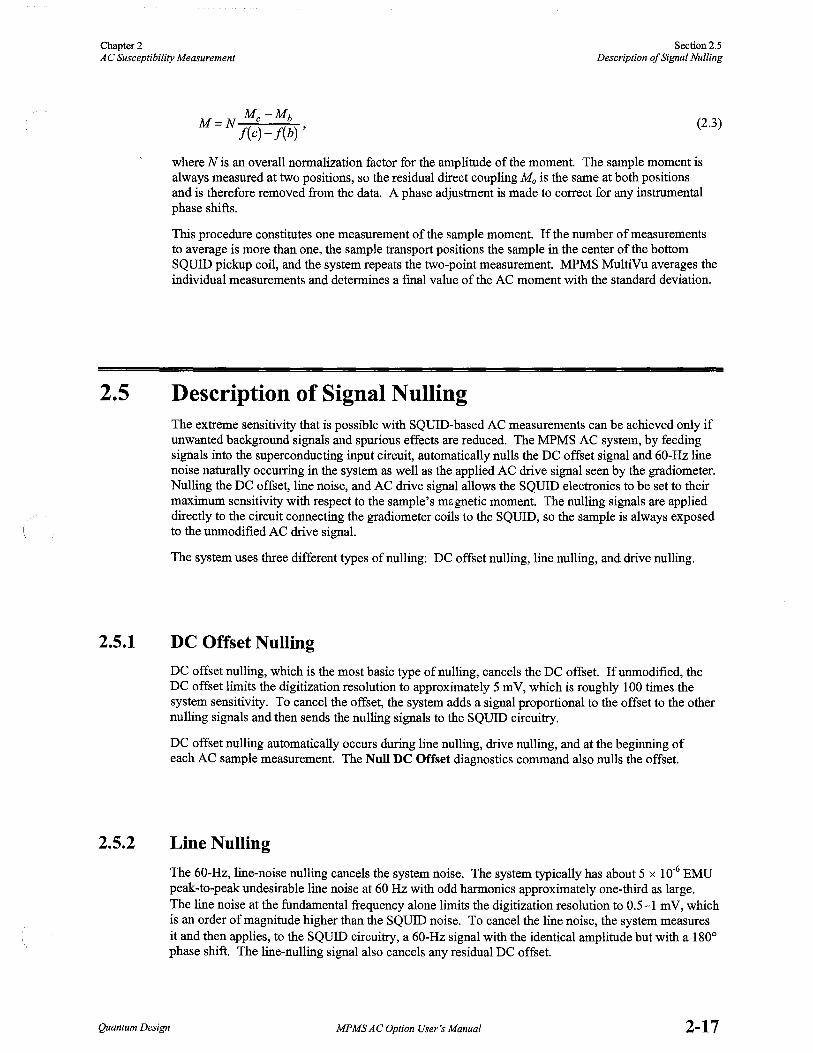
Mc-Mb M=N f(c)-f(b)' (2.3)
where N is an overall normalization factor for the amplitude of the moment. The sample moment is always measured at two positions, so the residual direct coupling M 0 is the same at both positions and is therefore removed from the data. A phase adjustment is made to correct for any instrumental phase shifts.
This procedure constitutes one measurement of the sample moment. If the number of measurements to average is more than one, the sample transport positions the sample in the center of the bottom SQUID pickup coil, and the system repeats the two-point measurement. MPMS MultiVu averages the individual measurements and determines a fmal value of the AC moment with the standard deviation.
2.5 Description of Signal Nulling
2.5.1
2.5.2
The extreme sensitivity that is possible with SQUID-based AC measurements can be achieved only if unwanted background signals and spurious effects are reduced. The MPMS AC system, by feeding signals into the superconducting input circuit, automatically nulls the DC offset signal and 60-Hz line noise naturally occurring in the system as well as the applied AC drive signal seen by the gradiometer. Nulling the DC offset, line noise, and AC drive signal allows the SQUID electronics to be set to their maximum sensitivity with respect to the sample's mi;gnetic moment. The nulling signals are applied directly to the circuit connecting the gradiometer coils to the SQUID, so the sample is always exposed to the unmodified AC drive signal.
The system uses three different types of nulling: DC offset nulling, line nulling, and drive nulling.
DC Offset Nulling
DC offset nulling, which is the most basic type of nulling, cancels the DC offset. If unmodified, the DC offset limits the digitization resolution to approximately 5 m V, which is roughly 100 times the system sensitivity. To cancel the offset, the system adds a signal proportional to the offset to the other nulling signals and then sends the nulling signals to the SQUID circuitry.
DC offset nulling automatically occurs during line nulling, drive nulling, and at the beginning of each AC sample measurement. The Null DC Offset diagnostics command also nulls the offset.
Line Nulling
The 60-Hz, line-noise nulling cancels the system noise. The system typically has about 5 x 10⁻⁶ EMU peak-to-peak undesirable line noise at 60 Hz with odd harmonics approximately one-third as large. The line noise at the fundamental frequency alone limits the digitization resolution to 0.5-1 mV, which is an order of magnitude higher than the SQUID noise. To cancel the line noise, the system measures it and then applies, to the SQUID circuitry, a 60-Hz signal with the identical amplitude but with a 180° phase shift. The line-nulling signal also cancels any residual DC offset.
Quantum Design MPMS AC Option User's Manual 2-17

Section 2.5 Description of Signal Nulling
Chapter 2 AC Susceptibility Measurement
2.5.3
2-18
Line nulling automatically occurs when MPMS MultiVu takes the first AC centering or AC sample measurement after system start-up or after the Model 1822 has been reset. Repeating line nulling at any other time is seldom necessary. You can, however, use the Null Line Noise diagnostics command to null the noise.
Drive Nulling
Drive nulling cancels the signals from the AC drive signal, the gradiometer imbalance, and the sample moment. To cancel these three signals, the system iteratively calculates a waveform that nulls the AC drive signal seen by the gradiometer. Nulling these signals maximizes the SQUID's sensitivity to the sample moment. Drive nulling is also called "applying the nulling waveform."
The MPMS AC system performs drive nulling before taking an AC centering or sample measurement. When the system sends a drive signal, it also calculates and sends the waveform required to null that signal. The system measures any remnant signal arising from an imperfect drive cancellation, and then uses the regression factor to make necessary corrections to the in-phase and out-of-phase components of the nulling waveform. The system applies the corrected nulling waveform and remeasures the net signal. The drive-nulling procedure is repeated until the amplitude of the wave iteration is smaller than the null amplitude parameter, the regression fit is less than 0.001, or the number of iterations exceeds 20. The system usually requires three to four iterations to read a 5 x 10⁻⁸ null in a drive field of 1 G.
The nulling waveform also cancels the DC offset and any 60-Hz line noise. The nulling waveform always cancels the DC offset, but cancels line noise only when line noise is present. Line noise is present when the system takes the first AC centering or sample measurement after system start-up or after the Model 1822 has been reset.
Drive nulling can reduce the residual AC signal in the SQUID detection system by four orders of magnitude, providing a total rejection of the AC drive signal of 1partin107
• This factor of 10,000 improvement can be achieved by using readily available precision electronic components. However, for the system to maintain such a high rejection level, the geometric stability of the drive and detection coils must be stable to the level ofrejection desired. The system's design creates this stability by making the AC drive coil an integral part of the superconducting DC magnet and by then combining the magnet and detection coils into a completely monolithic structure. All these elements reside in the liquid helium bath and thus remain at a constant temperature throughout the measurements, so phase shifts and changes in coil geometry are minimized.
The Apply Nulling Waveform command in the AC Center Parameters dialog box (see figure 2-6) disables drive nulling only during AC centering measurements. Quantum Design recommends that drive nulling be disabled during AC centering. The extreme precision that nulling allows is unnecessary during centering, and nulling greatly increases the time necessary to complete a centering measurement.
MPMSAC Option User's Manual Quantum Design

CHAPTER 3
AC System Calibration
3.1 Introduction This chapter contains the following information:
• Section 3 .2 presents an overview of sys~em calibration.
• Section 3 .3 describes the process of calibrating the instrument response.
3.2 Overview of Calibration
• Section 3.4 describes the process of performing an absolute calibration.
Calibration of an AC susceptometer requires two separate operations. First you identify and remove the inherent response of the instrument as it varies with the amplitude of the applied field, frequency, and temperature. Next you perform an absolute calibration of the instrument at a suitable amplitude, frequency, and temperature.
3.3 Instrument Response Calibration To calibrate the intrinsic response of the MPMS AC system, you measure a sample with a known dependence on a field, frequency, and temperature. You should ideally use a sample with a precisely calibrated amplitude and phase response that is a function of both frequency and temperature. Accurate calibration standards for AC measurements are not available commercially. However, by selecting a material whose imaginary component of the susceptibility X" is zero, you can calibrate amplitude and phase separately. Dysprosium (III) oxide (Dy20 3) is an electrical insulator with a large paramagnetic susceptibility. In the frequency range of0.001 to 1000 Hz, its moment is in phase with the applied field; that is, it is assumed that any component due to resistive or other dissipative mechanisms is too small to measure in the AC system. By knowing thatX" is always zero for Dy20 3, you can determine the phase response.
Quantum Design MPMS AC Option User's Manual 3-1

Section 3.3 Instrument Response Calibration
Chapter 3 AC System Calibration
3-2
You determine the intrinsic response of an instrument by measuring two components: distortions in the field applied to the sample and distortions in the measured sample moment. The field you want to apply to the sample is Ha. The actual field in the sample chamber is the applied internal field Ha, which has an amplitude change and phase shift relative to Ha. The induced sample moment is Ms. The measured sample moment Mm has an amplitude and phase shift relative to Ms because of the intervening body of the instrument and the measuring circuit. The determination and removal of the amplitude and phase shifts in Ha and Mm relative to Ha and Ms are discussed below.
Three concentric tubes made of high-resistivity material thermally isolate the sample from the liquid helium bath. These tubes are located between the copper solenoid, which produces the AC drive current, and the sample. The tubes produce frequency and temperature-dependent attenuation and phase shift in the excitation field applied to the sample. In addition, the amplifier circuit producing the AC drive current contains a 5-kHz, one-pole filter. You can directly determine the frequency and temperature dependence of the amplitude of the field applied to the sample; you simply use a copper solenoid connected to a spectrum analyzer to measure the field in the sample chamber. The temperature dependence of Ha is sufficiently small over the range of 2 to 400 K that no correction to the applied field for changes in the sample temperature is necessary. To account for the frequency dependence of the amplitude, the experimental data obtained from the test solenoid at 175 K is stored in a calibration table called genampad. cal. The data is used to supply the necessary compensation to the amplitude of the applied field Ha and subsequently to Ha.
Determining the absolute phase of the field applied to the sample is unnecessary because the absolute phase has no physical significance. Changes in the phase of Ha due to frequency or temperature changes are accounted for during the removal of phase shifts in the measured signal Mm that is caused by the instrument itself.
The most difficult effects to determine are distortions to the measured AC moment caused by the intrinsic frequency response of the instrument. Fortunately, the frequency response is independent of the amplitude of the AC drive field; this does not imply, however, that the measured amplitude is independent of frequency. Thus you need only consider calibration of the frequency and temperature dependence of the amplitude and phase of the measured signal.
Regarding temperature dependence, only the temperature of the inner vacuum sleeve and the sample chamber tube vary when the sample temperature changes. The SQUID pickup coils and various filters and amplifiers present elsewhere in the circuit remain unchanged. At very low frequencies, there is no change in the amplitude and phase shift in the measured signal due to the inner vacuum sleeve and sample chamber tube as a function of temperature. Consequently, any temperature-dependent effects measured at low frequencies are attributed to the sample and not the system. For example, the calibration material Dy20 3 is paramagnetic and shows the usual 1 IT dependence of its moment at low frequencies, so you normalize all frequency-dependent variations in the measurements to the low-frequency values at all temperatures.
Before the signal is digitized, it passes through one of five selectable low-pass filters. The MPMS AC system automatically selects a filter. The wave frequency determines which filter is selected. Discontinuities in the frequency dependence of the measured signal from these filters are automatically removed by a second-order interpolation procedure that uses a table generated during calibration.
The knowledge that the phase of the susceptibility ofDy20 3 is zero (X" = 0) is sufficient to calibrate the phase of the sample field as well as the phase shift between Ms and Mm. This is because the phase shift in the applied field and the intrinsic phase shift of the instrument always appear together and do not need to be separately determined. By setting the measured phase shift in Mm to zero for Dy20 3,
you remove both individual phase adjustments from the data.
MPMSAC Option User's Manual Quantum Design

Cllllpter 3 AC System Calibration
Section 3.4 Absolute Calibration
In addition to varying the AC field amplitude, temperature, and frequency, you can apply DC fields up to 5 T in either direction along the sample chamber axis. The presence of a DC field produces small amplitude shifts in the applied AC field via field-induced changes in the screening properties of the superconducting magnet wire and the normal conductors present. You correct the amplitude shifts by using the test coil at different DC fields to measure the internal field. At 5 T, the measured AC field value is larger than that expected by an amount varying from 2% at 10 Hz to 0.2% at 1 kHz. This effect is accounted for in the software controlling the AC drive coil so that the field applied to the sample is always the field you have specified.
3.4 Absolute Calibration To perform an absolute calibration of the MPMS AC system, you normalize the measured in-phase and out-of-phase susceptibilities X' and X" with a sample of known magnetic moment. Absolute calibration requires a sample known to have negligible frequency dependence in its measured moment, a large susceptibility that is linear in the required range of fields, and no screening currents that can change its effective shape. Again, Dy20 3 is a suitable sample.
You calibrate the AC measurement by comparing it to a DC measurement. You compare AC and DC measurements because the AC and DC systems use the identical pickup coils and SQUID detection system, and the DC system is calibrated from palladium reference standards supplied by the National Institute of Standards and Technology (NIST). First, you take DC measurements of the Dy203 sample at several low DC fields. You then repeat the measurement at the same temperature by using a DC field set by the AC solenoid. The system compares the susceptibilities to measure the BI I (gauss/amp) ratio of the AC solenoid. The BI I ratio is recorded as Coil Cal 2 in the Low Field calibration group. Next, you take AC measurements at a low frequency. The system compares the AC and DC susceptibilities and adjusts the AC regression factor to ensure that the AC and DC susceptibilities compare as expected. The AC regression factor is an AC calibration factor.
Sine wave generation and analysis are entirely digital, so calibration of the absolute value of a measured phase is trivial because both the wave period and the interval between data points are precisely known. The ultimate accuracy with which the phase may be determined is related to the stability of the crystal oscillator controlling all timing signals in the digital circuitry and therefore places no limitations on the system.
If the inherent sensor noise of the SQUID is the limiting noise source, you can estimate the system noise level from the noise characteristics of the SQUID detector and the coupling factors between the SQUID and its detection coils. The SQUID noise referenced to its input is about 6 pA/(Hz)112
(above 0.1 Hz), giving a detector sensitivity for a single SQUID reading of approximately 6 x 10·12
A· m2/(Hz) 112, referenced to the corresponding value of magnetic moment. System sensitivity has been shown to reflect the noise characteristics of the SQUID detector.
Quantum Design MPMS AC Option User's Manual 3-3

CHAPTER 4
AC Sequence Commands I
4.1 Introduction This chapter contains the following information:
• Section 4.2 describes the AC sequence commands.
4.2 Description of AC Sequence Commands
4.2.1
The MPMS AC option includes center, measure, calibration factor, and diagnostic sequence commands that affect AC operation. The sequence commands automate many of the same tasks, such as running a measurement, you can perform in immediate mode. AC sequence commands may be included in a sequence file with any other standard MPMS sequence commands, so you can use the full functional range of the MPMS MultiVu application while you work with the AC option.
The Magnetic Property Measurement System: MPMS MultiVu Application User's Manual discusses sequence files and all standard MPMS sequence commands in detail.
AC Center and Measure Sequence Commands
4.2.1.1 AC CENTER
AC Center runs an AC centering measurement. The AC centering measurement uses whatever parameters were last specified with the AC Parameters command. Consequently, in a sequence, AC Parameters should precede AC Center. AC Center should precede the Adjust Position command.
AC Center is in the Center command group in the sequence command bar.
Section 2.3.4 discusses the AC centering measurement in more detail.
Quantum Design MPMSAC Option User's Manual 4-1

Section 4.2 Description of AC Sequence Commands
Chapter4 AC Sequence Commands
4-2
4.2.1.2 AC PARAMETERS
AC Parameters defines the AC measurement and SQUID parameters used during the sequencemode AC centering measurement. In a sequence, AC Parameters should precede AC Center.
AC Parameters is in the Center command group in the sequence command bar.
Section 2.3.4.2 discusses in more detail the procedures for setting the centering measurement parameters.
4.2.1.3 MEASURE AC
Measure AC runs an AC sample measurement and defines the AC measurement and SQUID parameters used during the sequence-mode measurement.
Measure AC is in the Measure command group in the sequence command bar.
Section 2.3.5 discusses the AC sample measurement and the measurement and SQUID parameters in more detail.
Measure AC £!
. - .... ---- ....... .
. '''~5mmuJ ilK J . < cil~~el f Figure 4-1. Measure AC Dialog Box for Sequence Mode
MPMS AC Option User's Manual Quantum Design

Chapter4 AC Sequence Commands
Section4.2 Description qf AC Sequence Commands
4.2.1.4 SCAN AC AMPLITUDE
Scan AC Amplitude sets a series of drive amplitudes in a specified amplitude range and thus changes the drive amplitude for each measurement taken within a control loop. Scan AC Amplitude ignores whatever drive amplitude the Measure AC or Amplitude command has set.
Scan AC Amplitude is a scan command. Scan commands, unlike other sequence commands, can instruct the MPMS to perform a task that has multiple parts. The scan command automatically creates a control loop, and the multipart task is performed inside the control loop. A control loop may include any number of other sequence commands, including other types of scan commands. The Magnetic Property Measurement System: MPMS MultiVu Application User's Manual discusses scan commands and control loop operation in detail.
- SCAN AC AMPLITUDE - £j
·. -1~a1~mi"Ku¥[UO~~e ::. <_fi~IA~crc!_~l5:21893 Oe
.,: 0-~P~~~jNumberof~Steps ::!] -, St~~f2
·'·'.J
Figure 4-2. Scan AC Amplitude Dialog Box
PARAMETER DEFINITION VALUES
Initial Amplitude First set point in amplitude range. 0.0001-5.2189 Oe
Final Amplitude Last set point in amplitude range. 0.0001-5.2189 Oe
Spacing Mode of spacing set points. Number of Steps Increments (Oe) Log Amplitude
Steps or Number of set points. Steps Increment Increment
Quantum Design MPMS AC Option User's Manual 4-3

Section4.2 Description of AC Sequence Commands
Chapter4 AC Sequence Commands
4-4
4.2.1.5 SCAN AC FREQUENCY
Scan AC Frequency sets a series of drive frequencies in a specified frequency range and thus changes the drive frequency for each measurement taken within a control loop. Scan AC Frequency ignores whatever frequency the Measure AC or Wave Frequency command has set.
Scan AC Frequency is a scan command. Scan commands, unlike other sequence commands, can instruct the MPMS to perform a task that has multiple parts. The scan command automatically creates a control loop, and the multipart task is performed inside the control loop. A control loop may include any number of other sequence commands, including other types of scan commands. The Magnetic Property Measurement System: MPMS MultiVu Application User's Manual discusses scan commands and control loop operation in detail.
- SCAN AC FREQUENCY - £!
!:'~'j~~F~q~~~cJl!~~oo~4s~~~ }Hi.2 ··•· i','.iHi.;Frequ;~~y~1~12.1 ~Hz ·
~t'~c;~~'!z~~;;~Sl;£;~±1 "''-"-'-'·-· .·-.. ·.-· · __ ,_:_;_·;--;;:·:o_-,:_.· __ ,_,
i· i'"T:p· ~~iiJJ ·. ].}~~ l• Figure 4-3. Scan AC Frequency Dialog Box
PARAMETER DEFINITION VALUES
Initial Frequency First set point in frequency range. 0.00035-1512.1 Hz
Final Frequency Last set point in frequency range. 0.00035-1512.1 Hz
Spacing Mode of spacing set points. Number of Steps Increments (Hz) Log Amplitude
Steps or Number of set points. Steps Increment Increment
MPMS AC Option User's Manual Quantum Design

Chapter4 AC Sequence Commands
Section 4.2 Description of AC Sequence Commands
4.2.2
CAUTION
AC Calibration Factor Sequence Commands
Calibration factor sequence commands change the AC calibration factors. These commands are in the Calibration Factors command subgroup, which is in the Diagnostic command group in the sequence command bar.
All AC calibration factor sequence commands have equivalent settings in the Calibration Factors dialog box. Section 5.2 discusses the AC calibration factors in more detail.
4.2.2.1
Quantum Design strongly recommends using only the default calibration factors. Calibration factors may be changed only if a later calibration test has been performed on the MPMS or if the MPMS must complete nonstandard tasks. Only personnel who are thoroughly familiar with the MPMS and its operation should change calibration factors.
CURRENT TO FLUX
Current to Flux sets the ratio of the feedback current to the SQUID signal that is used for calculating the waveform required to null the AC drive signal.
4.2.2.2 DRIVE RESOLUTION
Drive Resolution sets the ratio of the low-resolution drive range to the high-resolution drive range. The drive resolution factor ensures that the transition between the low and high drive ranges occurs smoothly.
4.2.2.3 NULL RESOLUTION
Null Resolution sets the ratio of the low-resolution nulling range to the high-resolution nulling range. The null resolution factor ensures that the transition Letween the low and high nulling ranges occurs smoothly.
4.2.2.4 REGRESSION
Regression sets the factor that the system uses to calculate the equivalent EMU value for the AC response and therefore ensure that AC measurements are consistent with DC measurements. The range of the regression factor is -5 to +5.
The regression factor is set during absolute calibration of the system.
Quantum Design MPMS AC Option User's Manual 4-5

Section4.2 Description of AC Sequence Commands
Chapter4 AC Sequence Commands
4.2.3
w NOTE
4-6
AC Diagnostic Sequence Commands
All AC diagnostic commands have equivalent settings in the AC Diagnostics dialog box. Section 5.3 discusses the AC diagnostics in more detail.
4.2.3.l
If an AC diagnostic command and an AC measure command define the identical parameter within a sequence, the system ignores the diagnostic command and uses the value set by the measure command.
ACCLOCKFREQUENCY
AC Clock Frequency determines the rate at which the system applies the AC drive signal and collects the resulting data.
4.2.3.2 AC FILTER
AC Filter selects the SQUID filter used for AC processes. The AC Filter command overrides the system-selected AC filter. If the wave frequency or clock frequency subsequently changes, the system continues to use the filter selected with AC Filter.
AC calibration is valid only if the appropriate clock frequency is used with the AC filter. The filter roll-off frequencies were chosen to give small phase shifts of less than 3 ° at the maximum-intended drive frequency for each sampling rate. Table 5-2 lists the clock frequency that must be used with each AC filter.
4.2.3.3 AMPLIFIER GAIN
Amplifier Gain defines the gain of the input amplifier, which is on the AC digitizer card. The gain value affects system operation only if autoranging is disabled. If autoranging is enabled, the system automatically adjusts the gain whenever DC offset nulling, line nulling, or an AC measurement is performed. The input amplifier gain may be x 1, x 10, or x 100.
4.2.3.4 AMPLITUDE
Amplitude defines the amplitude of the AC drive signal the system applies to the sample. The drive amplitude may be any value from 0.0001 to 5.21893 Oe.
MPMSAC Option User's Manual Quantum Design

Chapter4 AC Sequence Commands
Section 4.2 Description of AC Sequence Commands
4.2.3.5 APPLY NULLING
Apply Nulling, when used in conjunction with the Signal Clocking command, generates a nulling signal that cancels the effect of the AC drive signal on the SQUID during sample measurements. Drive nulling must be enabled for the system to accurately measure AC susceptibility. By default, drive nulling is enabled during sample measurements. If you disable drive nulling, the SQUID sees the AC drive signal. Apply Nulling does not affect drive nulling during centering measurements.
4.2.3.6 NULL DC OFFSET
Null DC Offset cancels the DC offset. Section 2.5.1 discusses DC offset nulling in detail.
4.2.3.7 NULL LINE NOISE
Null Line Noise cancels the system noise. Section 2.5.2 discusses line nulling in detail.
4.2.3.8 SIGNAL CLOCKING
Signal Clocking sends a drive signal to the Model 1822. The drive signal starts the clock that controls the output of the signals. If nulling is enabled, Signal Clocking also sends a nulling signal. Signal Clocking keeps the signals synchronized.
4.2.3.9 STEPS PER CYCLE
Steps per Cycle determines the number of points the system uses to generate the wave frequency and the number of data points the system collects during each cycle of data. The number of steps per cycle must be an integer.
4.2.3.10 TWO-POINT MEASUREMENT
Two-Point Measurement enables two-point AC sample measurements. Two-point measurements, which are more accurate but slower than one-point measurements, are the system default. A two-point measurement nulls all field signals except the sample signal and allows an extremely accurate measurement of AC susceptibility. If you disable two-point measurements, the system takes a one-point measurement at the current position of the sample transport.
4.2.3.11 WAVE FREQUENCY
Wave Frequency defines the frequency of the AC drive signal the system applies to the sample. The wave frequency may be any value from 0.00035 to 1512.1 Hz.
Quantum Design MPMS AC Option User's Manual 4-7


CHAPTER 5
AC Calibration Factors and Diagnostics
5.1 Introduction This chapter contains the following information:
• Section 5.2 discusses the AC calibration factors.
• Section 5.3 discusses the AC diagnostics.
5.2 AC Calibration Factors
CAUTION
The AC calibration factors ensure the accuracy of AC measurements and set the limits of the AC drive signal and nulling waveform. The default AC calibration factors are set at the Quantum Design factory to ensure that the calibration reflects the unique attributes of the AC MPMS system.
All AC calibration factors are listed in the AC group, which is in the Calibration Factors dialog box (see figure 5-1 on the following page). You open the Calibration Factors dialog box by selecting the Utilities>Calibration option. The AC group consists of the current-to-flux ratio, drive resolution factor, null resolution factor, and regression factor.
Quantum Design strongly recommends using only the default calibration factors. Calibration factors may be changed only if a later calibration test has been performed on the MPMS or if the MPMS must complete nonstandard tasks. Only personnel who are thoroughly familiar with the MPMS and its operation should change calibration factors.
You select a calibration factor by either double-clicking on it in the AC group or by clicking on it once and then clicking on the Change button that is near the upper right comer of the Calibration Factors dialog box. When you select a calibration factor, a pop-up dialog box opens, listing the current value of the calibration factor. If you enter a new value and then select OK, you change the calibration factor.
Quantum Design MPMSACOption User's Manual 5-1

Section 5.2 AC Calibration Factors
Chapter 5 AC Calibration Factors and Diagnostics
5-2
Calibration Factms 13
Magnet (1450. 000) Longitudinal SQUID (7500.000) Transverse SQUID (7500.000) Field Penetration (0.000) Longitudinal E Ktended Range (300. 000) Transverse EKtended Range (300.000) Longitudinal Regression Factor (1.825) Transverse Regression Factor (1.825) Minimum data points (8) Transverse Rotator steps/degree (96.0000)
± SQUID settle time ± Temperature !±1 Low Field
BB Current to fluK ratio (·1.000000) Drive resolution factor (100.00000) Null resolution factor (1 00. 00000) Regression factor (0.625000)
± RSO
Figure 5-1. AC Group in Calibration Factors Dialog Box
Table 5-1. AC Calibration Factors
CALIBRATION FACTOR PARAMETER DEFINED
Current-to-Flux Ratio Ratio of feedback current to SQUID signal that is used for calculating waveform required to null AC drive signal.
Drive Resolution Factor Ratio of low-resolution drive range to high-resolution drive range. Drive resolution factor ensures that transi-tion between low and high drive ranges is smooth.
Null Resolution Factor Ratio of low-resolution nulling range to high-resolution nulling range. Null resolution factor ensures that transi-tion between low and high nulling ranges is smooth.
Regression Factor Factor the system uses to calculate equivalent EMU value for AC response and therefore ensure that AC measurements are consistent with DC measurements. Range ofregression factor is -5 to +5. Regression factor is set during absolute calibration of the system.
MPMS AC Option User's Manual
DEFAULT
VALUE
-1.000
100.000
100.000
0.625
Quantum Design

Chapter 5 AC Calibration Factors and Diagnostics
Section 5.3 AC Diagnostics
5.3 AC Diagnostics
Quantum Design
The AC diagnostic settings define several AC measurement parameters and set the rate at which the drive and nulling signals are sent and data is collected. The two AC diagnostic control commands immediately null the DC offset or the system noise. All AC diagnostics are in the AC Diagnostics dialog box (see figure 5-2), which you open by selecting the Utilities> Diagnostics> AC option.
Most diagnostic settings are system specific or are determined by current system settings. You change the value of a diagnostic setting by either selecting an option or entering a value and then clicking on the corresponding Set button in the AC Diagnostics dialog box. Any change made to a measurement parameter also appears in the AC Measurement dialog box.
AC Diagnostics l!!llil Ei [~el\i~. - .....
]"G:~f:~~~~,~I~oogo_,~2,,, [t]:;L'1; ;:;:;.
:llf ''•..,Qli> :Emo . g ~ ·~ + ·. _;;~~~~~~~~J~s~.627 • ·. . .. Set
::n;-f~~~~1iy~f ~::~~9~000··--~·;_ •• -.::.•.
1 ~5,~@_CIO~irif ' On; n •.. Off .•
--~· J~P9i;li}vl~~~~i.p": w~~N~~rigo~9ir; l APPtYNulfih9Waveiqn1l:J~ ..
Figure 5-2. AC Diagnostics Dialog Box
All AC diagnostic settings----except Write Nulling Diag---and controls have equivalent sequence commands. If you want to change diagnostic parameters automatically, run a sequence that includes the appropriate diagnostic commands. Section 4.2.2 discusses the AC diagnostic sequence commands.
MPMSAC Option User's Manual 5-3

Section 5.3 Chapter 5 AC Diagnostics AC Calibration Factors and Diagnostics
5.3.1 AC Diagnostic Settings
5-4
5.3.1.1 DRIVE AMPLITUDE
Drive Amplitude defines the amplitude of the AC drive signal the system applies to the sample. The drive amplitude may be any value from 0.0001 to 5.21893 Oe.
5.3.1.2 AC FILTER
AC Filter selects the SQUID filter used for AC processes. The AC Filter command overrides the system-selected AC filter. If the wave frequency or clock frequency subsequently changes, the system continues to use the filter selected with AC Filter.
AC calibration is valid only ifthe appropriate clock :frequency is used with the AC filter. The filter roll-off frequencies were chosen to give small phase shifts ofless than 3° at the maximum-intended drive frequency for each sampling rate. The following table lists the clock :frequency that must be used with each AC filter.
Table 5-2. Clock Frequencies Used to Validate AC Calibration
AC FILTER CLOCK FREQUENCY
None Used only with DC measurements
5Hz 45.776 Hz
lOHz Used only with DC measurements
80Hz 732.42 Hz
1200Hz 11718 Hz
5000Hz 187500 Hz
20,000 Hz 187500 Hz
Elliptical Used only with DC measurements
5.3.1.3 GAIN
Gain defines the gain of the input amplifier, which is on the AC digitizer card. The gain value affects system operation only if autoranging is disabled. If autoranging is enabled, the system automatically adjusts the gain whenever DC offset nulling, line nulling, or an AC measurement is performed. The input amplifier gain may be xl, xlO, or xlOO.
MPMSAC Option User's Manual Quantum Design

Chapter 5 AC Calibration Factors and Diagnostics
Section 5.3 AC Diagnostics
5.3.1.4 WAVE FREQUENCY
Wave Frequency defines the frequency of the AC drive signal the system applies to the sample. The wave frequency maybe any value from 0.00035 to 1512.1 Hz.
The wave frequency is a function of the clock frequency and the number of steps per cycle:
ClockFrequency WaveFrequency = S, p C l teps er ye e
When the wave frequency changes, the system makes whatever adjustments are necessary to the clock frequency and to the number of steps per cycle. Consequently, when the clock frequency or number of steps changes, the system makes whatever adjustments are necessary to the wave frequency. Both the clock frequency and number of steps per cycle must have discrete values: the clock frequency is fixed, and the number of steps must be an integer. The wave frequency that the system uses may vary slightly from the wave frequency you specify.
When the wave frequency changes and you have not used the AC Filter setting to select an AC filter, the system selects the optimal AC filter for the new wave frequency.
5.3.1.5 CLOCK FREQUENCY
Clock Frequency determines the rate at which the system applies the AC drive signal and collects the resulting data.
The clock frequency, which is one of five system-defined values, is a function of the wave frequency and the number of steps per cycle. When the clock frequency changes, the system makes whatever adjustments are necessary to the wave frequency and to the number of steps per cycle. Consequently, when the wave frequency or number of steps changes, the system makes whatever adjustments are necessary to the clock frequency.
Table 5-3. System-Defined Clock Frequencies
CLOCK STEPS PER WAVE FREQUENCY CYCLE FREQUENCY
2.861 512-8191 0.0056-0.0003
45.776 512-8191 0.0894-0.0056
732.42 512-8191 1.4305-0.0894
11719 512-8191 22.888-1.4307
187500 124-8190 1512.1-22.894
When the clock frequency changes and you have not used the AC Filter setting to select an AC filter, the system selects the optimal AC filter for the new clock frequency.
Quantum Design MPMS AC Option User's Manual 5-5

Section 5.3 AC Diagnostics
5-6
5.3.1.6 STEPS PER CYCLE
Chapter 5 AC Calibration Factors and Diagnostics
Steps per Cycle determines the number of points the system uses to generate the wave frequency and the number of data points the system collects during each cycle of data. The number of steps per cycle must be an integer.
The number of steps per cycle is a function of the clock frequency and the wave frequency:
S P C l ClockFrequency
teps er ye e = . WaveFrequency
When the steps per cycle changes, the system makes whatever adjustments are necessary to the clock frequency and to the wave frequency. Consequently, when the clock frequency or wave frequency changes, the system makes whatever adjustments are necessary to the number of steps per cycle.
The number of steps per cycle also defines the memory available to store data points:
2 MaxBlocks = S ,
where S is the number of steps per cycle.
5.3.1.7 SIGNAL CLOCKING
Signal Clocking sends a drive signal to the Model 1822. The drive signal starts the clock that controls the output of the signals. If the Apply Nulling Waveform setting is enabled, Signal Clocking also sends a nulling signal. Signal Clocking keeps the signals synchronized.
By default, signal clocking is turned on. If you tum off signal clocking, then at the end of the current wave cycle, the Model 1822 stops the clock controlling the signal output.
5.3.1.8 TWO-POINT MEASUREMENT
Two-Point Measurement enables two-point AC sample measurements. Two-point measurements, which are more accurate but slower than one-point measurements, are the system default. A two-point measurement nulls all field signals except the sample signal and allows an extremely accurate measurement of AC susceptibility. If you disable two-point measurements, the system takes a one-point measurement at the current position of the sample transport.
5.3.1.9 APPLY NULLING WAVEFORM
Apply Nulling Waveform, when used in conjunction with the Signal Clocking command, generates a nulling signal that cancels the effect of the AC drive signal on the SQUID during sample measurements. Drive nulling must be enabled for the system to accurately measure AC susceptibility. By default, drive nulling is enabled during sample measurements. If you disable drive nulling, the SQUID sees the AC drive signal. Apply Nulling Waveform does not affect drive nulling during centering measurements.
MPMSACOption User's Manual Quantum Design

Chapter 5 AC Calibration Factors and Diagnostics
Section 5.3 AC Diagnostics
5.3.2
Quantum Design
5.3.1.10 WRITE NULLING DIAG
Write Nulling Diag generates two data files: the drive file and the null file. By default, Write Nulling Diag is disabled in order to conserve disk space.
The drive, or . drv, file records the angle and voltage of the drive waveform that is used during the measurement. One block of voltages is written to the . drv file at the end of each measurement.
The null, or . nul, file records waveform characteristics of the nulling drive signal that is generated during the measurement. A new waveform is generated only when you change the AC parameters.
AC Diagnostic Controls
5.3.2.1 NULL DC OFFSET
Null DC Offset cancels the DC offset. Section 2.5.1 discusses DC offset nulling in detail.
5.3.2.2 NULL LINE NOISE
Null Line Noise cancels the system noise. Section 2.5.2 discusses line nulling in detail.
MPMS AC Option User's Manual 5-7


APPENDIX A
Data File Format
A.1
A.2
A.2.1
Introduction This appendix contains the following information:
• Section A.2 describes and illustrates the AC data file format.
Format of Data Files
• Section A.3 discusses the various data types.
Every data file consists of a header section and a data section. The header defines the type of data stored in the file and the default graph format of the file. The data section lists the actual stored data. Headers contain the same type of information. Data sections contain data that is specific to the measurement option that generated the data and to the type of data stored in the file.
The format of the data files is designed such that the files may be easily imported by other graphic applications, such as Microsoft Excel. The data file format is comma delimited.
Data File Header
The data file header is created when the data file is created, and the data file header can never be overwritten.
The data file header is preceded by the following bracketed keyword:
[Header]
The Title line contains the string that appears at the top of the graph view of the data file.
TITLE, MPMS AC Measurement
The By App line specifies which application and measurement option created the file.
BYAPP, MPMS Measurement, 1.0, Summary
Quantum Design MPMS AC Option User's Manual A-1

SectionA.2 Format of Data Files
Appendix A Data File Format
A-2
The FileOpenTime line indicates the numerical timestamp and the timestamp's formatted text of the time at which the file was created.
FILEOPENTIME, 889141960.579000 3/5/1998, 3:52:40 PM
The Info lines supply additional information about the measurement. MPMS MultiVu does not use the information in the Info section when it plots the data.
INFO, NAME, My Sample INFO, WEIGHT, 1.000 INFO, AREA, 1.000 INFO, LENGTH, 1.000 INFO, SHAPE, 0 INFO, COMMENT, INFO, SEQUENCE FILE: Pause.MV.Seq
The StartupAxes lines indicate which two axes are displayed in the graph view of the data file and which data item is assigned to each axis. The StartupAxes lines also indicate whether data is scaled logarithmically or linearly on the axis, whether the axis is automatically or manually scaled, and the minimum and maximum value for the axis.
STARTUPAXIS, X, 4, LINEAR, AUTO, 0.000000, 0.000000 STARTUPAXIS, Yl, 5, LINEAR, AUTO, 0.000000, 0.000000
The StartupGroup line indicates which field group is the default group for the graph data selection.
STARTUPGROUP, Longitudinal
The FieldGroup lines indicate which data selection items are included in each field group. The FieldGroup lines list the data items in the numerical urder of their appearance in the file.
FIELDGROUP, Longitudinal, 1, 2, 3, 4, 5, 6, 7, 8 ,9 19 FIELDGROUP, Transverse, 1, 2, 3, 4, 10, 11, 12, 13, 14 19
The PlotAppearance line defines the plot appearance of the graph view of the data file.
PLOT_APPEARANCE, ALL, HORZ_GRID_ON, VERT_GRID_ON, MARKERS AND LINES
MPMS AC Option User's Manual Quantum Design
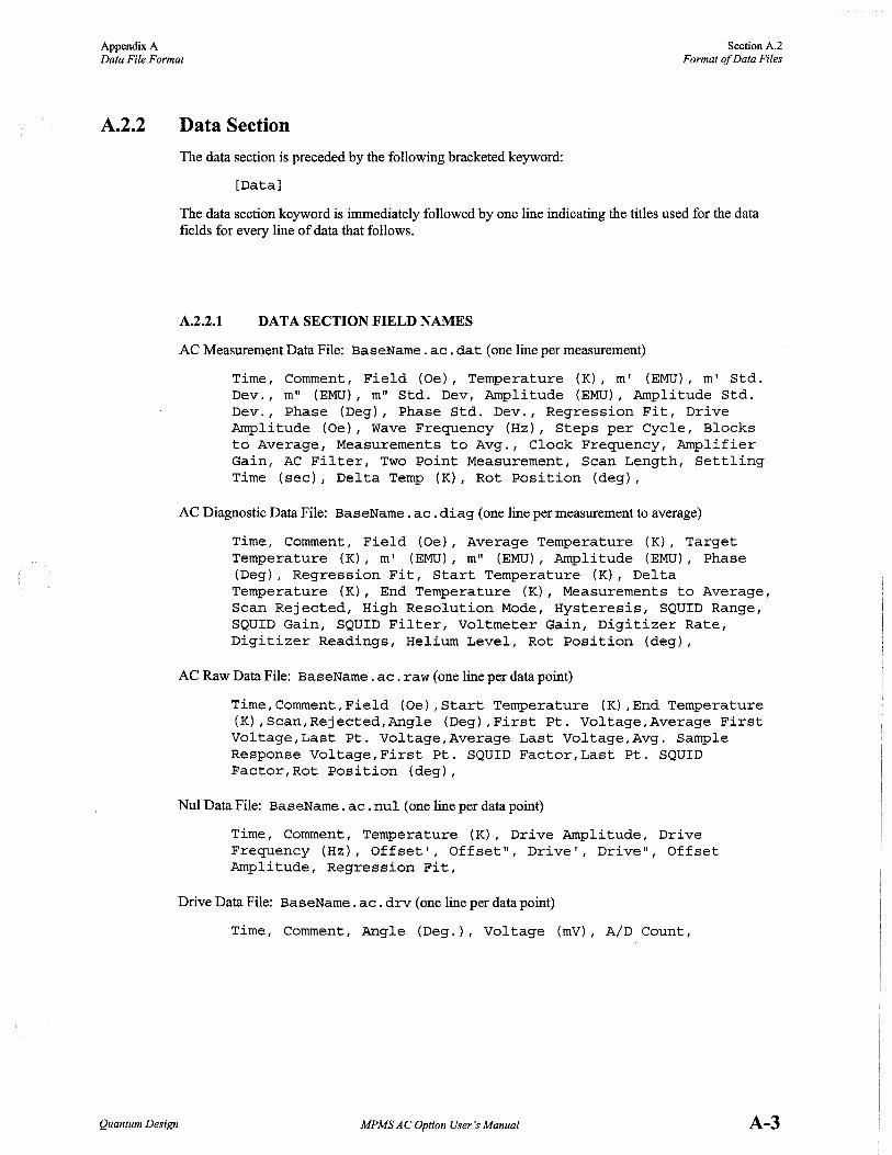
Appendix A Data File Format
SectionA.2 Format of Data Files
A.2.2
Quantum Design
Data Section
The data section is preceded by the following bracketed keyword:
[Data]
The data section keyword is immediately followed by one line indicating the titles used for the data fields for every line of data that follows.
A.2.2.1 DATA SECTION FIELD NAMES
AC Measurement Data File: BaseName. ac. dat (one line per measurement)
Time, Comment, Field (Oe), Temperature (K), m' (EMU), m' Std. Dev., m" (EMU), m" Std. Dev, Amplitude (EMU), Amplitude Std. Dev., Phase (Deg), Phase Std. Dev., Regression Fit, Drive Amplitude (Oe), Wave Frequency (Hz), Steps per Cycle, Blocks to Average, Measurements to Avg., Clock Frequency, Amplifier Gain, AC Filter, Two Point Measurement, Scan Length, Settling Time (sec), Delta Temp (K), Rot Position (deg),
AC Diagnostic Data File: BaseName. ac. diag (one line per measurement to average)
Time, Comment, Field (Oe), Average Temperature (K), Target Temperature (K), m' (EMU), m" (EMU), Amplitude (EMU), Phase (Deg), Regression Fit, Start Temperature (K), Delta Temperature (K), End Temperature (K), Measurements to Average, Scan Rejected, High Resolution Mode, Hysteresis, SQUID Range, SQUID Gain, SQUID Filter, Voltmeter Gain, Digitizer Rate, Digitizer Readings, Helium Level, Rot Position (deg),
AC Raw Data File: BaseName. ac. raw (one line per data point)
Time,Comment,Field (Oe),Start Temperature (K),End Temperature (K),Scan,Rejected,Angle (Deg),First Pt. Voltage,Average First Voltage,Last Pt. Voltage,Average Last Voltage,Avg. Sample Response Voltage,First Pt. SQUID Factor,Last Pt. SQUID Factor,Rot Position (deg),
Nul Data File: BaseName. ac . nul (one line per data point)
Time, Comment, Temperature (K), Drive Amplitude, Drive Frequency (Hz), Offset', Offset", Drive', Drive", Offset Amplitude, Regression Fit,
Drive Data File: BaseName. ac. drv (one line per data point)
Time, Comment, Angle (Deg.)., Voltage (mV), A/D Count,
MPMSACOption User's Manual A-3

Section A.3 Appendix A Data Types Data File Format
A.3 Data Types
A.3.1 Numerical Data
A.3.2
A.3.3
A.3.4
A-4
Numerical data in a data file may be stored in any standard floating point or integer format with the fields separated by commas. Note, however, that when data is read from the file, any floating point number that is read into an integer variable is truncated.
Strings
Strings are not delimited by quotation marks, apostrophes, or commas. Furthermore, only one string should be assigned to each line and no other fields should be on that line. In this format, strings may then contain any punctuation and can be entered by the appropriate line-entry command in the language of choice.
Boolean
Boolean variables should be represented as integers 0 or 1, where 0 indicates FALSE and 1 indicates TRUE.
Additional Information
This section describes some of the data file fields in more detail.
High Res Mode Enabled (Boolean): 0 =Disabled 1 =Enabled This only returns the software status and does not reflect the fact that above 5000 G the system charges the magnet with the Low Resolution resistor.
Rotator Position: If the rotator option is not installed, 0 is always returned.
Hysteresis: 0 = Magnet is persistent 1 = Magnet is not persistent
SQUID Number: 2 = Transverse 1 = Longitudinal
MPMSACOption User's Manual Quantum Design

Appendix A Data File Format
Quantum Design
Range+ (X_Range * 10): Range is an integer:
O=Xl 1 =XlO 2=Xl00 3 =XIOOO
X_Range is a Boolean: O=OFF l=ON
Values for "Range+ (X_Range * 10)" are Extended range OFF= 0, 1, 2, 3 Extended range ON = 10, 11, 12, 13
Gain (Integer): 0 =XI 1 =X2 2 = X5 3 =XlO
Voltmeter Digitizer Gain: See Gain
Filter (Integer): 0 = 20,000 Hz (AC orRSO) 1 = 5000 Hz (AC or RSO) 2 = 1200 Hz (AC or RSO) 3 = lOOHz
= 80 Hz (AC or RSO) 4 = lOHz 5 = 1 Hz
= 5 Hz (AC or RSO) 6 = Elliptical 7 =None
Rate (Integer): 1=60Hz 2 = 180Hz
Scan Type (Integer): 1 =Full scan 2 = Linear regression 3 = Iterative regression
MPMS AC Option User's Manual
SectionA.3 Data Types
A-5


References
Quantum Design. 1999. Magnetic Property Measurement System: MPMS MultiVu Application User's Manual.
1999. Magnetic Property Measurement System: Reciprocating Sample Option User's Manual.
1990. MPMS Hardware Reference Manual.
Quantum Design MPMS AC Option User's Manual References-1


Index
Absolute calibration, for AC system, 3-3. See also Instrument response calibration
AC centering measurement aborting, 2-10 advantages, 2-7 data file, 2-7, 2-10 defining parameters for, 2-8-2-9 plot of, 2-10 procedures,2-7-2-11
AC Center sequence command, 4-1 AC digitizer, description of, 1-3 AC drive system, description of, 1-3 AC filter diagnostic setting, 5-4 AC measurement parameters, list of, 2-12 AC option
calibration factors. See Calibration factors combining AC drive field with SQUID system, 1-2 diagnostics. See Diagnostics electronics, overview of, 1-3 measurement. See AC susceptibility measurement measurement range, 1-2 sample types, 1-2 sequence commands, 4-1-4-7 software, overview of, 1-4
AC Parameters sequence command, 4-2 AC susceptibility measurement
aborting, 2-15 coordinate system options, 2-13 data files, 2-11 description, 2-15, 2-16-2-17 diagnostic settings, 5-3-5-7 overview, 2-1 parameters, list of, 2-12 procedures, 2-2-2-15
attaching sample, 2-2-2-3 centering sample, 2-7-2-11 defining sample parameters, 2-6 inserting sample in sample chamber, 2-3-2-5 measuring sample, 2-11, 2-13-2-15
sample transport options, 2-2 stabilizing system conditions for, 2-11
AC susceptometer, operation of, 1-1 Amplifier gain
for AC centering measurement, 2-9 for AC susceptibility measurement, 2-13 diagnostic setting, 5-4
Autoranging, caution against disabling, 2-9, 2-14 Autotracking
caution against disabling, 2-9, 2-14 effect on sample transport initialization, 2-7
Blocks-to-average parameter for AC centering measurement, 2-9 for AC susceptibility measurement, 2-14
Calibration, 3-1-3-3 Calibration factors
list of, 5-2 overview, 5-1 sequence commands, 4-5
center.ac.lastscan file plot of, 2-10 saving centering measurement data, 2-7, 2-10
Centering measurement, types of, 2-7. See also AC centering measurement
Clock frequency diagnostic setting, 5-5 Current-to-flux ratio, 5-2
Data files data types in, A-4-A-5 format, A-1-A-3 selecting for AC susceptibility measurement, 2-14 storing AC centering measurement data, 2-7, 2-10 storing sample measurement data, 2-11 viewing, 2-15
.dat file saving sample measurement data, 2-11 saving sample parameter data, 2-6, 2-14 selecting, 2-14
DC centering measurement, suggested usage, 2-7 DC offset nulling
command, 4-7, 5-7 description, 2-17
Diagnostic data file, saving data to, 2-14 Diagnostics
controls, 5-7 overview, 5-3 sequence commands, 4-6-4-7 settings, 5-4-5-7
Drive amplitude for AC centering measurement, 2-8 for AC susceptibility measurement, 2-13 diagnostic setting, 5-4
Drive file, 5-7 Drive nulling
description, 2-18 disabling during centering measurement, 2-9, 2-18 importance for AC susceptibility measurement, 2-11
Drive resolution factor, 5-2
Quantum Design MPMSAC Option User's Manual Index-1

Index
Electronics, for AC system, overview of, 1-3
Instrument response calibration, for AC system, 3-1-3-3. See also Absolute calibration
.lastscan file, 2-11 Line nulling
command, 4-7, 5-7 description, 2-17-2-18
Measure AC sequence command, 4-2 Measurement. See AC susceptibility measurement M0asurement data file. See .<lat file Measurements-to-average parameter
for AC centering measurement, 2-9 for AC susceptibility measurement, 2-14
MPMS MultiVu application, controlling AC system, 1-4
Null amplitude for AC centering measurement, 2-9 for AC susceptibility measurement, 2-13
Null file, 5-7 Nulling, types of, 2-17 Null resolution factor, 5-2
One-point measurement, enabling, 2-11
Raw data file, saving data to, 2-14 Regression factor, 5-2
Sample attaching to sample rod, 2-2-2-3 centering, 2-7-2-11 inserting in sample chamber, 2-3-2-5 measuring for AC susceptibility, 2-11, 2-13-2-15 parameters, saving to data file, 2-6 types for AC susceptibility measurements, 1-2
Sample transport initializing, 2-7 options for AC susceptibility measurements, 2-2
Scan AC Amplitude sequence command, 4-3 Scan AC Frequency sequence command, 4-4 Scan data file, 2-11 Settling time
for AC centering measurement, 2-9 for AC susceptibility measurement, 2-14
Signal nulling, description of, 2-17-2-18 Software, for AC system, 1-4 SQUID parameters, list of, 2-12 SQUID settling time. See Settling time Steps-per-cycle diagnostic setting, 5-6
Two-point measurement. See also AC susceptibility measurement: Description
as default for AC susceptibility measurement, 2-11 enabling, 5-6 procedures for, 2-13-2-15
Wave frequency for AC centering measurement, 2-8 for AC susceptibility measurement, 2-13 diagnostic setting, 5-5
Index-2 MPMS AC Option User's Manual Quantum Design