magnetic cores made of amorphous alloys - go-gddq.com
TRANSCRIPT

Introduction 1
AMOS
AMOSENSE
Introduction
Amorphous alloys are produced by rapid solidification technology of molten metal at coolingrates of about a million degrees centigrade per second. During this step the metal is rapidlyquenched as a ribbon with liquid-like internal structure.
The good soft magnetic properties of amorphous alloys principally arise from thehomogeneous and isotropic amorphous structure. As amorphous alloys have evolved intouseful applications, more development have followed.
The main constituents for electromagnetic applications are Fe - and Co - based amorphousalloys. More recently, the nanocrystalline materials are also used in all the electronic areas.Various magnetic properties such as permeability, coercive force field, rectangular ratio andso on could be obtained by suitable heat treatment according to application area.
Magnetic CoresMade ofAmorphous Alloys

2 AMOSENSE
General Information of Amorphous Alloy Introduction
>>>> Atomic Structure
>>>> Characteristics Technology of rapid solidification process Excellent magnetic property Strip thickness of 15μm to 25μm High electrical resistivity Low core loss at high frequency
Miniaturization of electronic equipment Excellent high frequency characteristics Spike current reduction Noise suppression Energy saving
DC/DC converter AC/DC converter Switch-mode power supply High frequency transformer Input noise reduction in automotive application of car audio Pulse transformer for telecommunication, xDSL, ADSL, VDSL Boost choke for power factor correction Current/voltage sensing Differential mode choke for inverter Common mode noise reduction choke Magnetic head Choke for temperature controlling circuit of automobile Flux-gate sensor for navigation system Magnetic tag for library, market Magnetic sensor for over-temperature in household transformer
>>>> Features
>>>> Major Applications
Crystalline Structure Amorphous Structure

Introduction 3
>>>> Saturation Induction vs. Coercivity
>>>> Permeability vs. Coercivity
3.0
2.5
2.0
1.5
1.0
0.5
0.010-3
107
106
105
104
106
102
10-3 10-2 10-1 100 101 102
10-2 10-1 100 101 102
Sa
tura
tio
n I
nd
uct
ion
(T
)
Coercivity (A/cm)
Pe
rme
ab
ility
Coercivity (A/cm)
Fe-based Amorphous alloy
Fe-based Amorphous alloy
Fe-Ni based Amorphous alloy
Fe-Ni based Amorphous alloyPermalloy powder
Soft ferrite
Sendust (Fe-Al-Si)
Supermalloy
78 Permalloy (Ni-Fe)
Ni-Zn Ferrite
Fe-3 wt.% SiPure Iron
Mn-Zn Ferrite
Fe-5 wt. % Co
Fe-3 wt. % Si
Fe-6.5 wt. % Si Iron & it’salloypowder
Carbon steel
Fe40~50Ni
Fe70~80Ni
Co-based Amorphous alloy
Co-based Amorphous alloy
Typical Properties of Soft Magnetic Alloys Introduction

4 AMOSENSE
>>>> Typical SMPS Circuit Diagram
>>>> Major Power Supply Applications
Application Material Series Part Code
Common Mode Choke Nano, Co-based Amorphous Alloy AMF, AMFN series
Differential-Mode Choke Fe-based Amorphous Alloy AMC, APH, AMCU series
PFC Boost Choke Fe-based Amorphous Alloy AMCU, APH, AMC series
Mag-Amp Co-based Amorphous Alloy AMSA series
Mag-Amp Nano-based Amorphous Alloy AMSN series
Output Choke Fe-based Amorphous Alloy APH, AMC, AMCU series
Bead Co-based Amorphous Alloy AMB series
Spike Killer Co-based Amorphous Alloy AMK series
Typical Application Circuit for SMPS Introduction

High Quality Mag-Amp Cores 5
AMOS
AMOSENSE
High Quality Mag-Amp Cores
Mag-Amp technique is one of simple, the most reliable and cost-effective postregulation ways of providing control on the secondary side of the auxiliary outputs inmultiple-output switch-mode power supplies. Therefore, Mag-Amp cores are now theindustry standard for implementing high precision and high efficiency independent ofoutputs in switch-mode power supplies of server, telecomm and personal computerapplications.
Adapting AMSA Mag-Amp gives following attractive benefits.
1. Shorten Design Time with Reduced Total CostSimple circuit construction with fewer component for the control circuit is achieved.
2. High ReliabilityMag-Amp can withstand instantaneous surges in current or voltage and protectoutput diode from voltage and current spike in circuit.
3. High Precision and Low NoiseThe output voltage kept in tightly from no load to full load conditions and noise fromoutput diode is suppressed by high inductance of Mag-Amp in series connectionwith diode.It's differ from semiconductor regulation(eg.MOS-FET) which adds switching noisein regulating circuit.
High squareness (~98%) Low coercive force field Low temperature rise High efficiency Low reset current requirement UL94V-0 compliant
>>>> Description
>>>> Feature
Magnetic Amplifiers for Switched mode power supplies.(PC,Server, OA) Magnetic Amplifiers for DC to DC Converter Power supplies for network products such as Hubs, etc. Adapter for notebook/laptop Oscillating transformer Other kinds of saturable reactors
>>>> Application
Product Summary High Quality Mag-Amp Cores
Hig
h Q
ualit
y M
ag-A
mp
Cor
es
6 AMOSENSE
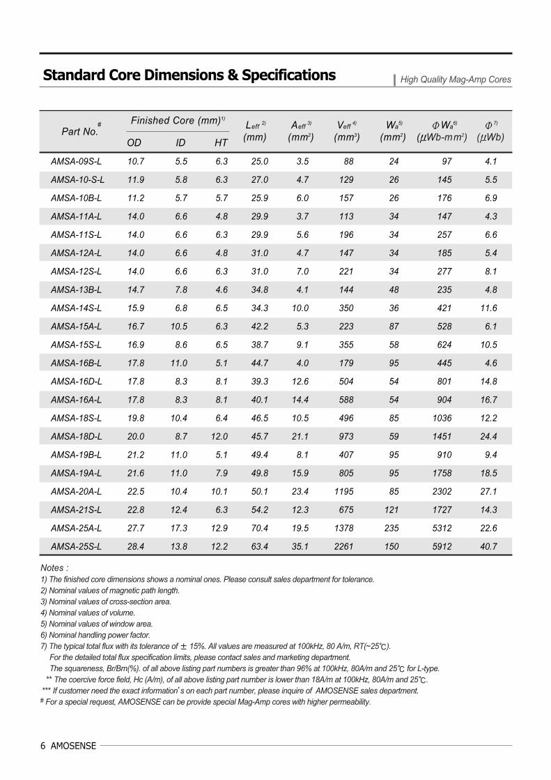
AMSA-09S-L 10.7 5.5 6.3 25.0 3.5 88 24 97 4.1
AMSA-10-S-L 11.9 5.8 6.3 27.0 4.7 129 26 145 5.5
AMSA-10B-L 11.2 5.7 5.7 25.9 6.0 157 26 176 6.9
AMSA-11A-L 14.0 6.6 4.8 29.9 3.7 113 34 147 4.3
AMSA-11S-L 14.0 6.6 6.3 29.9 5.6 196 34 257 6.6
AMSA-12A-L 14.0 6.6 4.8 31.0 4.7 147 34 185 5.4
AMSA-12S-L 14.0 6.6 6.3 31.0 7.0 221 34 277 8.1
AMSA-13B-L 14.7 7.8 4.6 34.8 4.1 144 48 235 4.8
AMSA-14S-L 15.9 6.8 6.5 34.3 10.0 350 36 421 11.6
AMSA-15A-L 16.7 10.5 6.3 42.2 5.3 223 87 528 6.1
AMSA-15S-L 16.9 8.6 6.5 38.7 9.1 355 58 624 10.5
AMSA-16B-L 17.8 11.0 5.1 44.7 4.0 179 95 445 4.6
AMSA-16D-L 17.8 8.3 8.1 39.3 12.6 504 54 801 14.8
AMSA-16A-L 17.8 8.3 8.1 40.1 14.4 588 54 904 16.7
AMSA-18S-L 19.8 10.4 6.4 46.5 10.5 496 85 1036 12.2
AMSA-18D-L 20.0 8.7 12.0 45.7 21.1 973 59 1451 24.4
AMSA-19B-L 21.2 11.0 5.1 49.4 8.1 407 95 910 9.4
AMSA-19A-L 21.6 11.0 7.9 49.8 15.9 805 95 1758 18.5
AMSA-20A-L 22.5 10.4 10.1 50.1 23.4 1195 85 2302 27.1
AMSA-21S-L 22.8 12.4 6.3 54.2 12.3 675 121 1727 14.3
AMSA-25A-L 27.7 17.3 12.9 70.4 19.5 1378 235 5312 22.6
AMSA-25S-L 28.4 13.8 12.2 63.4 35.1 2261 150 5912 40.7
Part No.Finished Core (mm)1)
OD ID HT
Leff2) Aeff
3) Veff 4) Wa
5) ΦWa6) Φ7)
(mm) (mm2) (mm3) (mm2) (μWb-mm2) (μWb)
Notes :1) The finished core dimensions shows a nominal ones. Please consult sales department for tolerance.2) Nominal values of magnetic path length.3) Nominal values of cross-section area.4) Nominal values of volume.5) Nominal values of window area.6) Nominal handling power factor.7) The typical total flux with its tolerance of ± 15%. All values are measured at 100kHz, 80 A/m, RT(~25).
For the detailed total flux specification limits, please contact sales and marketing department.The squareness, Br/Bm(%). of all above listing part numbers is greater than 96% at 100kHz, 80A/m and 25 for L-type.
** The coercive force field, Hc (A/m), of all above listing part number is lower than 18A/m at 100kHz, 80A/m and 25.*** If customer need the exact information’s on each part number, please inquire of AMOSENSE sales department.
# For a special request, AMOSENSE can be provide special Mag-Amp cores with higher permeability.
Standard Core Dimensions & Specifications High Quality Mag-Amp Cores
#
High Quality Mag-Amp Cores 7
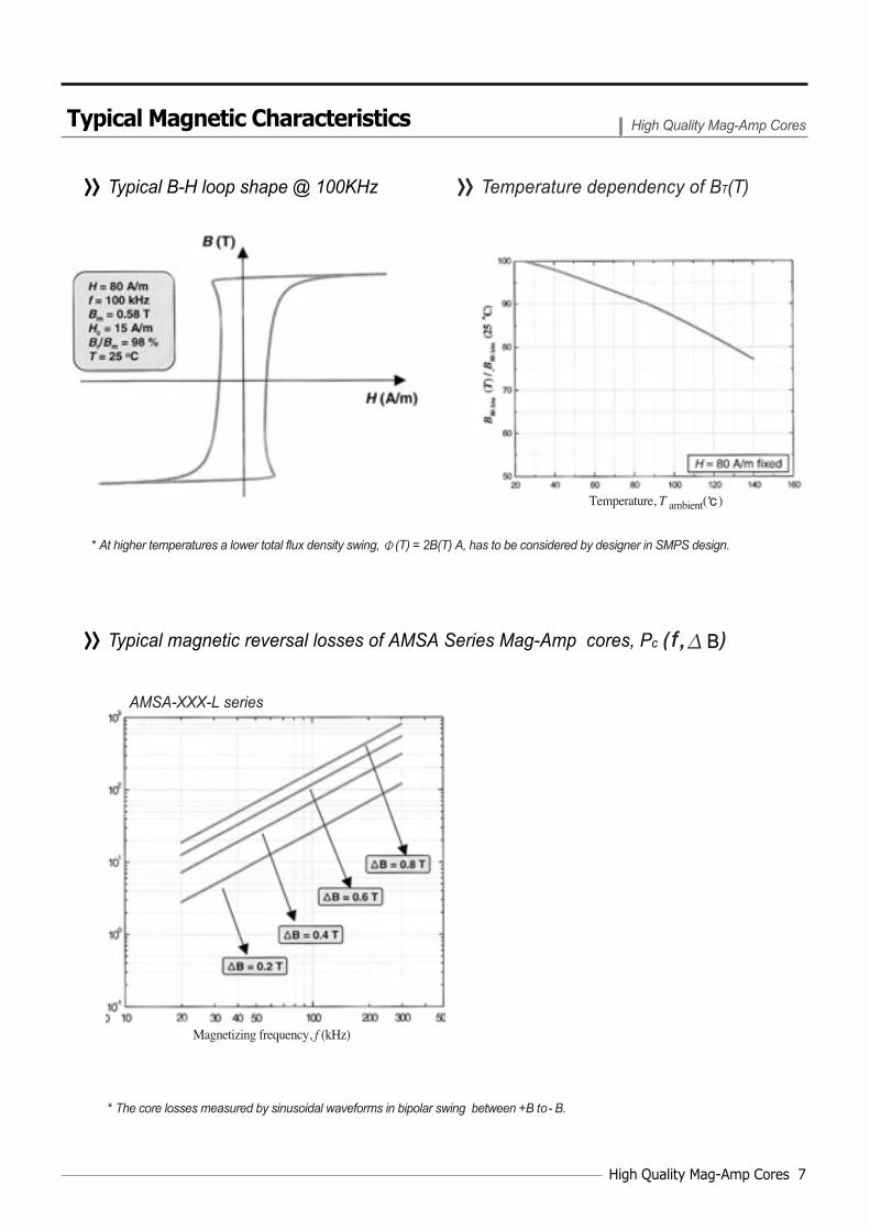
>>>> Typical B-H loop shape @ 100KHz
>>>> Typical magnetic reversal losses of AMSA Series Mag-Amp cores, Pc ( f , B)
>>>> Temperature dependency of BT(T)
* At higher temperatures a lower total flux density swing, Φ(T) = 2B(T) A, has to be considered by designer in SMPS design.
* The core losses measured by sinusoidal waveforms in bipolar swing between +B to- B.
Typical Magnetic Characteristics High Quality Mag-Amp Cores
Magnetizing frequency, f (kHz)
Temperature, T ambient()
AMSA-XXX-L series
8 AMOSENSE
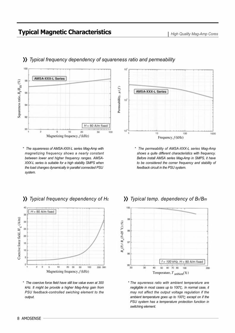
>>>> Typical frequency dependency of squareness ratio and permeability
>>>> Typical frequency dependency of Hc >>>> Typical temp. dependency of Br/Bm
* The squareness of AMSA-XXX-L series Mag-Amp withmagnetizing frequency shows a nearly constantbetween lower and higher frequency ranges. AMSA-XXX-L series is suitable for a high stability SMPS whenthe load changes dynamically in parallel connected PSUsystem.
* The permeability of AMSA-XXX-L series Mag-Ampshows a quite different characteristics with frequency.Before install AMSA series Mag-Amp in SMPS, it haveto be considered the corner frequency and stability offeedback circuit in the PSU system.
* The coercive force field have still low value even at 300kHz. It might be provide a higher Mag-Amp gain fromPSU feedback-controlled swiching element to theoutput.
* The squreness ratio with ambient temperature arenegligible in most cases up to 100. In normal case, itmay not affect the output voltage regulation if theambient temperature goes up to 100 except on if thePSU system has a temperature protection function inswitching element.
Typical Magnetic Characteristics High Quality Mag-Amp Cores
Temperature, T ambient()Magnetizing frequency, f (kHz)
Coe
rciv
e fo
rce
field
, H c
(A/m
)Sq
uare
ness
ratio
, Br/B
m (%
)
Frequency, f (kHz)Magnetizing frequency, f (kHz)

Nanocrystalline Mag-Amp Core 9
AMOS
AMOSENSE
Nanocrystalline Mag-Amp Core
AMSN series nanocrystalline Mag-Amp cores are now available by AMOSENSE'sinnovated technology. The nanocrystalline Mag-Amp cores are manufactured with anew class of iron-based nanocrystalline soft magnetic alloys, FeCuNbSiB.
Since the nanocrystalline materials have a relatively high electrical resistivity ofabout 120μΩ- cm and a ribbon thickness of about 18 ~ 24 μm the eddy currentlosses are relatively low up to frequencies of about 100 kHz. As an applications inswitch-mode power supply, the high saturation magnetic induction of 1.2 T andthermal stability would give it a distinct advantage over many existing materials.
And with its very high squareness is an another choice for switch-mode powersupply engineers to design Mag-Amp circuits for secondary output voltage regulationwhich are highly cost-effective in general purpose power supplies.
Adapting AMSN Mag-Amp gives following attractive benefits.
1. Cut Down the Cost Smaller in component size with the help of large saturation magnetic inductiongives cost effective circuit design.
2. High Temperature OperatingHigher Curie temperature of material enables operating up to 120.
3. High Precision RegulationHigh squareness and relatively low coercive force enable precision regulation.
High saturation flux density of 1.2 T Smaller component size Extended operating temperature range up to 120
>>>> Description
>>>> Feature
Product Summary Nanocrystalline Mag-Amp Core
>>>> Application Magnetic Amplifiers for switched mode power supplies Power supplies for personal computer Open-frame switched-mode power supplies Precise output voltage control such as
3.3 V, 5 V and 12 V in SMPS Other kinds of saturable reactor
Hig
h Q
ualit
y M
ag-A
mp
Cor
esN
anoc
ryst
allin
eM
ag-A
mp
Cor
eN
anoc
ryst
allin
eM
ag-A
mp
Cor
eN
anoc
ryst
allin
eM
ag-A
mp
Cor
eN
anoc
ryst
allin
eM
ag-A
mp
Cor
eN
anoc
ryst
allin
eM
ag-A
mp
Cor
eN
anoc
ryst
allin
eM
ag-A
mp
Cor
eN
anoc
ryst
allin
eM
ag-A
mp
Cor
eN
anoc
ryst
allin
eM
ag-A
mp
Cor
e

10 AMOSENSE
>>>> Typical B-H loop shape @ 100KHz >>>> Typical losses, Pc ( f , B)
Standard Core Dimensions & Specifications Nanocrystalline Mag-Amp Core
AMSN -10B-L 11.2 5.7 5.7 26.1 5.6 148 26 344 13.5
AMSN -11S-L 14.0 6.6 6.3 29.6 5.3 157 34 431 12.6
AMSN -13B-L 14.7 7.8 4.6 34.8 4.1 144 49 485 9.9
AMSN -15S-L 16.9 8.6 6.5 38.7 8.8 345 59 1254 21.1
AMSN -18S-L 19.8 10.4 6.4 45.7 9.5 438 85 1928 22.7
Part No.Finished Core (mm)1)
OD ID HT
Leff2) Aeff
3) Veff 4) Wa
5) ΦWa6) Φ7)
(mm) (mm2) (mm3) (mm2) (μWb-mm2) (μWb)
Notes :1) The finished core dimensions shows a nominal ones. Please consult sales department for
tolerance.2) Nominal values of magnetic path length.3) Nominal values of cross-section area.4) Nominal values of volume.5) Nominal values of window area.6) Nominal Handling power factor.7)Total flux with its tolerances of ±15 %. All values are measured at 100 kHz, 80 A/m, RT (~ 25).* The squareness, Br/Bm (%), of all above listing part numbers is greater than 96 % at 100 kHz, 80 A/m and 25.** The coercive force field, Hc (A/m), of all above listing part numbers is lower than 36 A/m
at 100 kHz, 80 A/m and 25.*** If customer need the exact information's on each part number, please inquire
of AMOSENSE sales department.
* The core losses measured by sinusoidal waveforms inbipolar swing between +B to -B.
Typical Magnetic Characteristics Nanocrystalline Mag-Amp Core
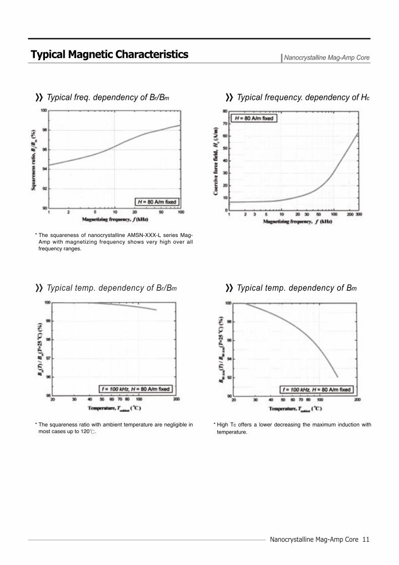
Typical Magnetic Characteristics Nanocrystalline Mag-Amp Core
* The squareness of nanocrystalline AMSN-XXX-L series Mag-Amp with magnetizing frequency shows very high over allfrequency ranges.
* High Tc offers a lower decreasing the maximum induction withtemperature.
>>>> Typical freq. dependency of Br/Bm >>>> Typical frequency. dependency of Hc
>>>> Typical temp. dependency of Bm
* The squareness ratio with ambient temperature are negligible inmost cases up to 120.
>>>> Typical temp. dependency of Br/Bm
Nanocrystalline Mag-Amp Core 11

AMOS
AMOSENSE
Common Mode Chokes
AMF Series magnetic cores of high permeability are now available that is made ofCo-based amorphous alloys. Furthermore, recently AMOSENSE launched newAMFN Series common mode choke cores which is made of nanocrystalline alloy.
Recently, electromagnetic inference(EMI) considerations are increasingly importantas electronic devices become part of our daily lives. This has rapidly increased therequired performanceces for electromagnetic compatibility(EMC) components such ascommon mode chokes coils, which provide protection against incoming and outgoinghigh frequency noise. They also protect electronc devices against high voltage pulsenoise generated by spark discharge, etc. These types of noise are created wheneverthere are rapid transitions in voltage and/or current waveforms. In switching powersupplies, the waveforms are periodic, but it’s waveforms are non-periodic in case ofdata line for telecommunication. The application area of common chokes covers allproducts from telecommunication product for signal transmitting to switch-mode powersupplies, frequency converters, and UPS units.
Common mode chokes are mainly used to provide attenuation of asymmetricalconducted inferences. Their design is determined by the specifications of thecorresponding international standards and the specific inference suppressionproblem.
AMF and AMFN Series common mode chokes shows a higher insertionattenuation, that is insertion damping, overall the wide-range of frequency. The typicalpermeability of AMF and AMFN Series common mode choke is 80,000. To satisfythese requirements, AMOSENSE will be provide a higher level of common modechokes with AMF and AMFN Series flat loop cores.
High permeability Reduce in size Reduce the winding turns Low DC resistance Low core loss Low power consumption High impedence overall the wide-range of frequency Meet the EN500081 and EN500082 standards Getting a sutable insertion loss in wide-range of frequency Low profile(1~5mm height)
>>>> Description
>>>> Feature
EMI common mode filtering Telecommunications and data communications interface transformers High accuracy current transformers High accuracy pulse transformers Ground fault protection devices
>>>> Application
Product Summary Common Mode Chokes
12 AMOSENSE
High Q
uality M
ag-Am
p Cores
Nanocrystalline
Mag-A
mp C
oreA
udio Chokes
Nanocrystalline
Mag-A
mp C
oreN
anocrystalline M
ag-Am
p Core
Com
mon M
odeC
hokesC
omm
on Mode
Chokes
Nanocrystalline
Mag-A
mp C
oreN
anocrystalline M
ag-Am
p Core

Common Mode Chokes 13
Standard Core Dimensions & Specifications Common Mode Chokes
AMFN-16A-TH
AMFN-20A-TH
AMFN-24A-TH
AMFN-25A-TH
AMFN-32S-TH
Part No.Finished Core (mm)1)
OD ID HT
Leff2) Aeff
3) Veff 4) SA5) AL
7)
(mm) (mm2) (mm3) (cm2) (μH)
Part No.Finished Core (mm)1)
OD ID HT Leff
2) Aeff 3) Veff
4) SA5) AL6)
(mm) (mm2) (mm3) (cm2) (μH)
Notes :1) The finished core dimensions shows a typical ones. Tolerance is ± 0.2 mm.2) Nominal values of magnetic path length.3) Nominal values of cross-section area.4) Nominal values of volume.5) Nominal value of surface area.6) Minimum value. Initial nominal inductance at 10 kHz, 0.1 Vosc @ RT.7) Typical value. Tolerance is *) -25~+45 % , **) -25~+40 % , ***) -/+ 30 % . Initial nominal inductance at 10 kHz, 0.1 Vosc @ RT.
>>>> AMF Series Co-based Common Mode Choke
>>>> AMFN Series Nanocrystalline Common Mode Choke
AMF-15A-T
AMF-12S-T
AMF-18S-T
AMF-25A-T
AMF-19A-T
AMF-10S-T
AMF-16A-T
AMF-20A-T
AMF-32S-T
16.7
14.0
19.8
27.7
21.6
11.3
17.8
22.5
33.7
10.5
6.6
10.4
17.3
11.0
5.3
8.3
10.4
19.4
17.8
22.5
27.7
27.7
33.7
8.3
10.4
17.3
17.3
19.4
8.1
10.1
12.9
12.9
11.9
40.8
50.1
70.6
70.6
82.0
14.4
23.4
20.0
20.0
42.0
588
1195
1414
1414
3490
6.13
12.00
17.67
17.67
25.3
41.4*)
57.0**)
22.5*)
28.4*)
66.0***)
6.3
6.3
6.4
12.9
7.9
5.6
8.1
10.1
11.9
42.2
31.0
46.5
70.4
49.7
25.5
40.1
50.1
82.0
7.0
7.0
10.5
19.5
15.7
6.1
10.5
23.4
41.0
297.7
220.5
496.2
1378.4
790.5
159.2
430.1
1194.6
3402.7
6.36
4.08
7.07
17.67
9.43
3.24
6.13
12.00
25.34
9.4
17.1
17.1
20.9
24.1
26.0
26.4
35.2
37.7
14 AMOSENSE
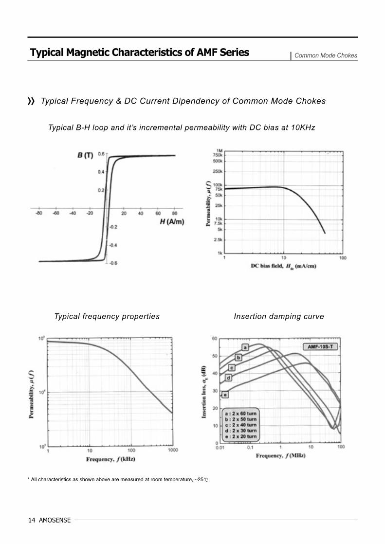
Typical Magnetic Characteristics of AMF Series Common Mode Chokes
Typical B-H loop and it’s incremental permeability with DC bias at 10KHz
Typical frequency properties Insertion damping curve
>>>> Typical Frequency & DC Current Dipendency of Common Mode Chokes
* All characteristics as shown above are measured at room temperature, ~25

Common Mode Chokes 15
Typical Magnetic Characteristics of AMF Series Common Mode Chokes
Typical μμpeak with flux density Typical temperature properties of μμ
Typical core loss Pc(f) Typical Pc(T)
* All characteristics as shown above are measured at room temperature, ~25

16 AMOSENSE
Typical Magnetic Characteristics of AMFN Series Common Mode Chokes
Typical frequency properties Typical incremental permeability
Typical μμpeak with flux density Typical core loss Pc(f)
>>>> Typical Frequency & DC Current Dipendency of Common Mode Chokes
* All characteristics as shown above are measured at room temperature, ~25
AMOS
AMOSENSE
Car Audio/Navigation Chokes
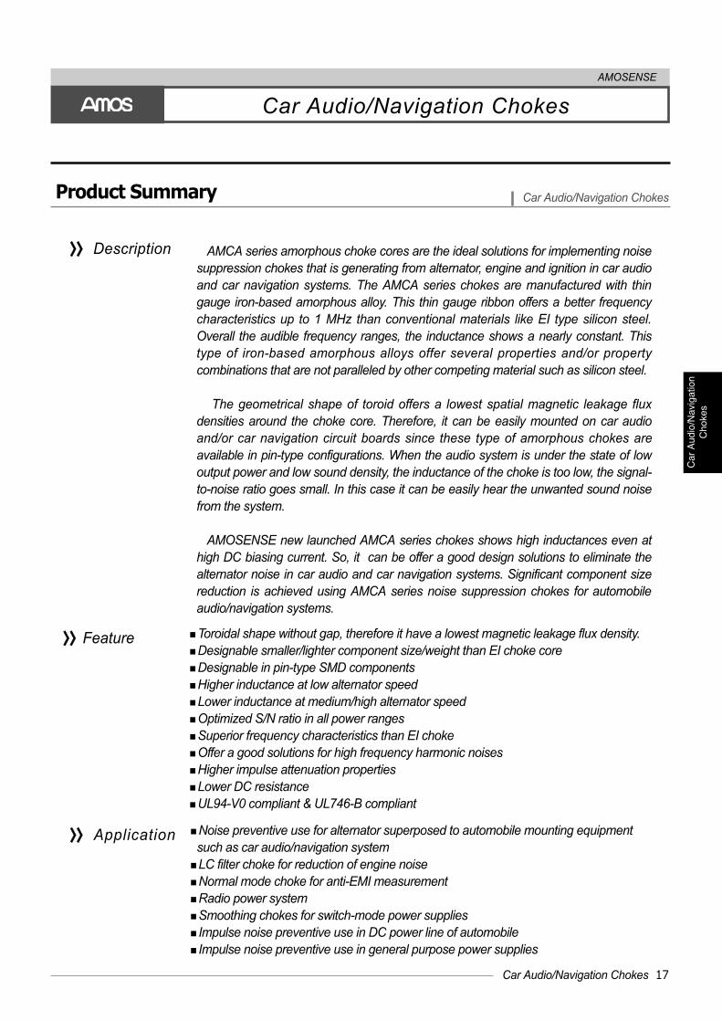
AMCA series amorphous choke cores are the ideal solutions for implementing noisesuppression chokes that is generating from alternator, engine and ignition in car audioand car navigation systems. The AMCA series chokes are manufactured with thingauge iron-based amorphous alloy. This thin gauge ribbon offers a better frequencycharacteristics up to 1 MHz than conventional materials like EI type silicon steel.Overall the audible frequency ranges, the inductance shows a nearly constant. Thistype of iron-based amorphous alloys offer several properties and/or propertycombinations that are not paralleled by other competing material such as silicon steel.
The geometrical shape of toroid offers a lowest spatial magnetic leakage fluxdensities around the choke core. Therefore, it can be easily mounted on car audioand/or car navigation circuit boards since these type of amorphous chokes areavailable in pin-type configurations. When the audio system is under the state of lowoutput power and low sound density, the inductance of the choke is too low, the signal-to-noise ratio goes small. In this case it can be easily hear the unwanted sound noisefrom the system.
AMOSENSE new launched AMCA series chokes shows high inductances even athigh DC biasing current. So, it can be offer a good design solutions to eliminate thealternator noise in car audio and car navigation systems. Significant component sizereduction is achieved using AMCA series noise suppression chokes for automobileaudio/navigation systems.
Toroidal shape without gap, therefore it have a lowest magnetic leakage flux density. Designable smaller/lighter component size/weight than EI choke core Designable in pin-type SMD components Higher inductance at low alternator speed Lower inductance at medium/high alternator speed Optimized S/N ratio in all power ranges Superior frequency characteristics than EI choke Offer a good solutions for high frequency harmonic noises Higher impulse attenuation properties Lower DC resistance UL94-V0 compliant & UL746-B compliant
>>>> Description
>>>> Feature
Noise preventive use for alternator superposed to automobile mounting equipmentsuch as car audio/navigation system
LC filter choke for reduction of engine noise Normal mode choke for anti-EMI measurement Radio power system Smoothing chokes for switch-mode power supplies Impulse noise preventive use in DC power line of automobile Impulse noise preventive use in general purpose power supplies
>>>> Application
Product Summary Car Audio/Navigation Chokes
Car Audio/Navigation Chokes 17
Hig
h Q
ualit
y M
ag-A
mp
Cor
esN
anoc
ryst
allin
e M
ag-A
mp
Cor
eA
udio
Cho
kes
Car
Aud
io/N
avig
atio
nC
hoke
sA
udio
Cho
kes
Com
mon
Mod
eC
hoke
sN
anoc
ryst
allin
e M
ag-A
mp
Cor
eN
anoc
ryst
allin
e M
ag-A
mp
Cor
eN
anoc
ryst
allin
e M
ag-A
mp
Cor
e

AMCA-11S-N 12.4 5.5 6.7 27.8 8.5 240 24 0.142 370
AMCA-12S-N 14.0 6.6 6.3 31.0 8.1 255 34 0.092 300
AMCA-15B-N 16.7 7.7 6.6 36.9 13.5 509 47 0.118 260
AMCA-16C-N* 17.2 6.8 4.2 36.3 10.2 385 36 0.250 740
AMCA-18B-N 20.0 8.7 12.0 44.7 31.5 1435 59 0.280 320
AMCA-18C-N 19.7 9.4 9.5 44.7 25.2 1148 69 0.602 850
AMCA-18A-N** 20.0 8.7 12.0 44.7 31.5 1435 59 0.785 890
AMCA-19B-N*** 20.8 8.3 6.6 44.1 16.6 892 54 0.340 630
AMCA-20S-N 22.0 10.7 11.8 49.2 36.0 1810 90 0.960 1050
Part No.Finished Core (mm)1)
OD ID HT
Leff2) Aeff
3) Veff 4) Wa
5) AL 6) μ7)
(mm) (mm2) (mm3) (mm2) (μH)
18 AMOSENSE
Notes :1) The finished core dimentions shows a nominal ones. Tolerance is ±0.2mm.2) Nominal values of magnetic path length.3) Nominal values of cross-section area.4) Nominal values of volume.5) Nominal values of window area.6) Typical value. Tolerance is ±25% of its initial AL value of each. Initial nominal inductance at 1kHz, 1VOSC and room temperature.
*AMCA-16C-N have a tolerance of +39% and -25% of its typical AL value.**AMCA-18A-N have a tolerance of +30% and -20% of its typical AL value.***AMCA-19B-N have a tolerance of +35% and -20% of its typical AL value.
7) Typical permeability of each part number. The permeability can change to improve the characteristics without notice.
Standard Core Dimensions & Specifications Car Audio/Navigation Chokes

Notes :
* Hysteresis losses are measured at room temperature, 25± 3.
** These curves were determined from AC magnetizing frequency with sinusoidal wavefroms.
*** Products generally do not fully comply with material characteristics : deviations may occur due to shape and size factor even if the core
has the same class of permeability.
Typical Hysteresis Loss with Permeability, Pc ( f ,μ) Car Audio/Navigation Chokes
Magnetic flux density swing, B (T)
Magnetic flux density swing, B (T) Magnetic flux density swing, B (T)
Permeability : 1000μclass
Permeability : 260μclass
Permeability : 320μclass
Car Audio/Navigation Chokes 19

20 AMOSENSE
>>>> Typical DC Bias characteristics of AMCA series choke with permeability
>>>> Typical percent permeability of 260μ& 1000μclass choke cores with frequency
* The deviations of DC bias characteristics, even if the permeability has the same, might be occur due to shape and size factor.
* The roll-off of percent permeability of 260u/1100u classes at 1MHz are around 10/20% of its 1kHz value, respectively.
Typical Magnetic & Electric Characteristics Car Audio/Navigation Chokes
Magnetizing force, H [Ampere-Turns]Magnetizing force, H [Ampere-Turns]
Frequency, f (kHz)
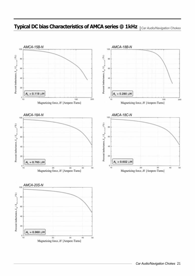
Typical DC bias Characteristics of AMCA series @ 1kHz Car Audio/Navigation Chokes
Magnetizing force, H [Ampere-Turns] Magnetizing force, H [Ampere-Turns]
AMCA-18B-NAMCA-15B-N
Magnetizing force, H [Ampere-Turns] Magnetizing force, H [Ampere-Turns]
AMCA-18C-NAMCA-18A-N
Magnetizing force, H [Ampere-Turns]
AMCA-20S-N
Car Audio/Navigation Chokes 21

22 AMOSENSE
AMOS
AMOSENSE
PFC & Output Choke Cores
AMC series amorphous choke cores are made of thin iron-based amorphous alloy.This type of iron-based amorphous alloys offer several properties that are notparalleled by other competing materials such as ferrites, iron-powder, sendust andpermalloys.
The iron-based amorphous alloy shows a high permeability, a high saturationinduction, low losses and high Curie temperature distinct from the operating one.
However, past days, most engineers in switch-mode power supply design could notuse the iron-based amorphous choke cores because of following two critical reasons:one is rather expensive and the other is higher temperature rise when comparedsuperpermalloy and sendust. Since the above mentioned reasons, iron-basedamorphous choke cores have been used in switch-mode power supply for the specialpurpose for the last few decades.
Now, with the introduction of our new AMC series choke core product range,AMOSENSE offer the real performance leader. Our expertise in iron-basedamorphous choke core manufacturing system has enabled us to significantly reducemagnetic losses and more higher DC bias characteristics to a level never beforeachieved ones. Furthermore, now it is available to use amorphous choke cores inswitch-mode power supply with a competitive price than other industry standardpower cores like sendust.
High saturation flux density of 1.56 T Significant size reduction Extended bias characteristics can store more higher energy capacity Lower hysteresis losses Higher efficiency Fewer winding turns result in lower copper losses UL94-V0 compliant
>>>> Description
>>>> Feature
Smoothing chokes for power supplies Multiple-winding coupled chokes for cross-regulation in switch-mode power supplies PFC chokes for general purpose industrial power supplies Output chokes for telecommunication power supply rectifiers PFC chokes for telecommunication power supply rectifiers DC/DC converter chokes PFC chokes for networking equipment power supplies Output chokes for general purpose industrial power supplies Differential input chokes Flyback transformers
>>>> Application
Product Summary PFC & Output Choke Cores
High Q
uality M
ag-Am
p Cores
Nanocrystalline
Mag-A
mp C
oreA
udio Chokes
PF
C &
Output
Choke e
PF
C &
Output
Choke e
Com
mon M
odeC
hokesN
anocrystalline M
ag-Am
p Core
Nanocrystalline
Mag-A
mp C
oreN
anocrystalline M
ag-Am
p Core

>>>> Dimension & Normalized inductance, AL, of AMC Series Choke Cores
AMC-12A-N 13.9 6.5 4.8 31.0 0.05 0.2 33.2 0.066 300
AMC-12S-N 14.2 6.4 6.5 31.0 0.08 0.3 32.2 0.092 270
AMC-15S-N 16.9 8.6 6.5 38.7 0.10 0.4 58.0 0.092 270
AMC-18S-N 19.6 10.4 6.3 46.5 0.12 0.6 84.9 0.089 270
AMC-22S-N 24.9 10.3 12.5 53.7 0.41 2.2 83.3 0.232 245
AMC-26S-N 28.4 13.8 12.2 64.7 0.45 3.0 150.0 0.214 245
AMC-32S-N 33.7 19.4 11.9 82.0 0.47 3.9 296.0 0.147 200
AMC-37S-N 39.4 20.8 12.1 92.5 0.63 5.9 340.0 0.188 220
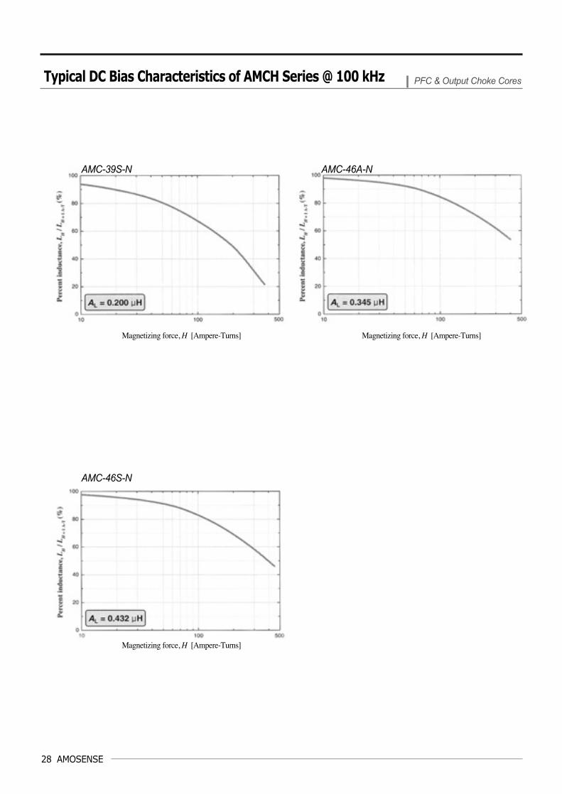
AMC-39S-N 40.7 23.4 15.3 99.0 0.78 7.8 430.0 0.200 200
AMC-46A-N 49.8 22.8 23.4 112.0 1.71 19.6 408.3 0.345 180
AMC-46S-N 49.8 22.8 28.3 112.0 2.14 24.5 408.3 0.432 180
Part No.Finished Core (mm)1)
OD ID HT
Leff2) Aeff
3) Veff 4) Wa
5) AL 6) μ7)
(mm) (cm2) (cm3) (mm2) (μH)
Notes :1) The finished core dimensions shows a typical ones. Tolerance is ±0.2mm2) Nominal values of magnetic path length. 3) Nominal values of cross-section area.4) Nominal values of volume. 5) Nominal values of window area.6) AL value with its tolerances of ±20%. All AL values are measured at 100kHz with the oscillation voltage of 1 Vosc. 7) Typical permeability of each part number. The permeability can change to improve the characteristics without notice.
Standard Core Dimensions & Specifications PFC & Output Choke Cores
PFC & Output Choke Cores 23
24 AMOSENSE
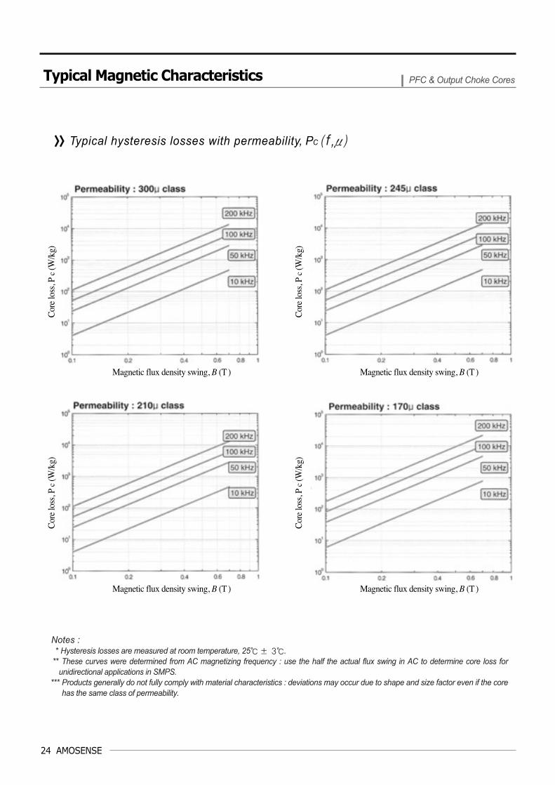
>>>> Typical hysteresis losses with permeability, PC ( f ,μ)
Notes :* Hysteresis losses are measured at room temperature, 25± 3.
** These curves were determined from AC magnetizing frequency : use the half the actual flux swing in AC to determine core loss forunidirectional applications in SMPS.
*** Products generally do not fully comply with material characteristics : deviations may occur due to shape and size factor even if the corehas the same class of permeability.
Typical Magnetic Characteristics PFC & Output Choke Cores
Magnetic flux density swing, B (T )
Cor
e lo
ss, P
c(W
/kg)
Cor
e lo
ss, P
c(W
/kg)
Cor
e lo
ss, P
c(W
/kg)
Cor
e lo
ss, P
c(W
/kg)
Magnetic flux density swing, B (T )
Magnetic flux density swing, B (T ) Magnetic flux density swing, B (T )

>>>> Typical DC Bias characteristics of AMC series choke with permeability
>>>> Typical Percent permeability with frequency
* The deviations of DC bias characteristics, even if the permeability has the same, might be occur due to shape and size factor.
* The roll-off of percent permeability at 1MHz is within 10% of its 1kHz value.
Typical Magnetic Characteristics PFC & Output Choke Cores
Magnetizing force, H (Ampere-Turns) Magnetizing force, H (Ampere-Turns)
PFC & Output Choke Cores 25

26 AMOSENSE
Typical DC Bias Characteristics of AMC Series @ 100 kHz PFC & Output Choke Cores
Magnetizing force, H [Ampere-Turns] Magnetizing force, H [Ampere-Turns]
Magnetizing force, H [Ampere-Turns] Magnetizing force, H [Ampere-Turns]
AMC-15S-N AMC-18S-N
AMC-12S-NAMC-12A-N

Typical DC Bias Characteristics of AMC Series @ 100 kHz PFC & Output Choke Cores
Magnetizing force, H [Ampere-Turns] Magnetizing force, H [Ampere-Turns]
AMC-37S-NAMC-32S-N
Magnetizing force, H [Ampere-Turns] Magnetizing force, H [Ampere-Turns]
AMC-22S-N AMC-26S-N
PFC & Output Choke Cores 27
28 AMOSENSE
Typical DC Bias Characteristics of AMCH Series @ 100 kHz PFC & Output Choke Cores
Magnetizing force, H [Ampere-Turns]
Magnetizing force, H [Ampere-Turns] Magnetizing force, H [Ampere-Turns]
AMC-46S-N
AMC-39S-N AMC-46A-N

AMOS
AMOSENSE
Cut-cores for High Power Applications
AMCU Series Cut cores are the ideal solutions for implementing energy storagechokes in several types of SMPS topologies even in high frequency ranges and highpower ranges.
Significant component size reduction and/or increased power throughput isachieved using AMCU Series Amorphous Cut cores. AMCU Series Amorphous Cutcores made by iron based thin amorphous ribbon with high saturation level of 1.5 T.With this high saturation level, AMCU Series Amorphous Cut cores enable up to 50 %reduction in volume for typical applications compared more conventional materials likeferrite, sendust, iron powder and silicon steel. The thin ribbon reduces the unwantededdy current losses at high frequencies. AMOSENSE new technology on Cut coremanufacturing ensures lower magnetic reversal losses than ever before.
AMCU Series amorphous Cut cores are being used in a growing number of highfrequency power applications.
AMOSENSE will offer a fully designed solutions and a customer oriented solutionswith a free design service whenever you need it.
Low eddy current losses Low hysteresis losses High efficiency Low temperature rise High saturation flux density Bsaturation = 1.56 T Smaller component size High power throughput More comprehensive range of component sizes than before UL94-V0 compliant UL Temp class F compliant
>>>> Description
>>>> Feature
PFC chokes for power supplies Output chokes for power supplies PFC choke for UPS system Harmonic choke for UPS system PFC choke for welding SMPS PFC choke for home appliance & industrial air conditioning Inverter choke for high power supplies PFC and output choke for distributed power front end Solar light power supplies X-ray power supplies Choke for induction furnaces Chokes for weight/efficiency sensitive applications in high speed rail car power supplies Choke for induction furnaces
>>>> Application
Product Summary Cut-cores for High Power Applications
Cut-cores for High Power Applications 29
Hig
h Q
ualit
y M
ag-A
mp
Cor
esN
anoc
ryst
allin
e M
ag-A
mp
Cor
eA
udio
Cho
kes
PF
C &
Out
put
Cho
ke e
Nan
ocry
stal
line
Mag
-Am
p C
ore
Cut
-cor
es fo
r Hig
hP
ower
App
licat
ions
Cut
-cor
es fo
r Hig
hP
ower
App
licat
ions
Nan
ocry
stal
line
Mag
-Am
p C
ore
Nan
ocry
stal
line
Mag
-Am
p C
ore

30 AMOSENSE
AMCU-4
AMCU-6.3
AMCU-8
AMCU-10
AMCU-16A
AMCU-16B
AMCU-20
AMCU-25
AMCU-32
AMCU-40
AMCU-50
AMCU-63
AMCU-80
AMCU-100
AMCU-125
AMCU-160
AMCU-200
AMCU-250
AMCU-320
AMCU-500
AMCU-630
AMCU-800A
AMCU-800B
AMCU-1000
Part Number Mass Lm AC Ve WA WAAc
(g) (cm) (cm2) (cm3) (cm2) (cm4)a b c d e f
* All mechanical dimensions shows a norminal ones. Please consult sales department for tolerances.
Standard Core Dimensions & Specifications Cut-cores for High Power Applications
9
10
11
11
11
11
11
13
13
13
16
16
16
16
19
19
19
19
22
25
25
25
30
33
10
11
13
13
13
13
13
15
15
15
20
20
20
20
25
25
25
25
35
40
40
40
40
40
33
33
30
40
40
50
50
56
56
56
70
70
70
70
83
83
83
90
85
85
85
85
95
105
15
20
20
20
25
25
30
25
30
35
25
30
40
45
35
40
50
60
50
55
70
85
85
85
29
31
35
35
35
35
35
41
41
41
52
52
52
52
63
63
63
63
79
90
90
90
100
106
51
53
52
62
62
72
72
82
82
82
102
102
102
102
121
121
121
128
129
135
135
135
155
171
95
150
170
200
250
280
340
380
460
530
590
710
950
1060
1170
1330
1670
2100
2170
2900
3670
4450
5930
7060
11.5
132
159
129
110
131
134
159
154
174
174
200
253
303
303
303
303
303
303
303
303
303
303
303
1.0
1.6
1.8
1.8
2.3
2.3
2.7
2.7
3.2
3.7
3.3
3.9
5.2
5.9
5.4
6.5
7.8
9.3
9.0
11.3
14.3
17.4
21.0
23.0
3.4
3.6
3.9
5.2
5.2
6.5
6.5
8.4
8.4
8.4
14.0
14.0
14.0
14.0
20.8
20.8
20.8
22.5
29.8
34.0
34.0
34.0
38.0
42.0
13.20
20.86
23.64
27.82
34.77
38.94
47.29
52.85
63.89
73.71
82.06
98.75
132.13
147.43
162.73
184.98
232.27
292.07
301.81
403.34
510.43
618.92
824.76
981.92
3.5
5.8
7.0
9.4
12.0
15.0
17.6
22.7
26.9
31.1
46.2
54.6
72.8
82.6
112.1
135.2
162.2
209.3
267.8
384.2
486.2
591.6
798.0
966.0
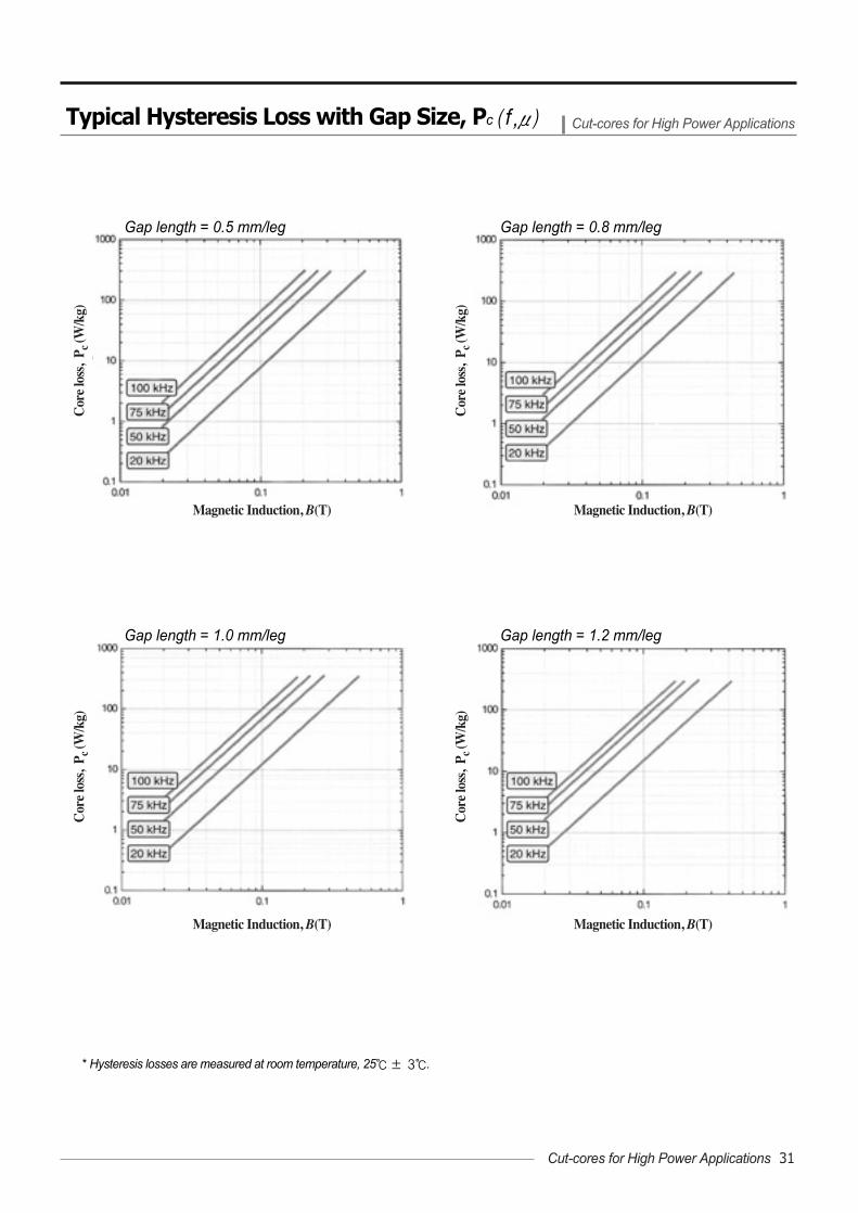
* Hysteresis losses are measured at room temperature, 25± 3.
Typical Hysteresis Loss with Gap Size, Pc ( f ,μ) Cut-cores for High Power Applications
Gap length = 1.0 mm/leg Gap length = 1.2 mm/leg
Gap length = 0.5 mm/leg Gap length = 0.8 mm/leg
Magnetic Induction, B(T) Magnetic Induction, B(T)
Magnetic Induction, B(T)
Cor
e lo
ss,
P c (W
/kg)
Cor
e lo
ss,
P c (W
/kg)
Cor
e lo
ss,
P c (W
/kg)
Cor
e lo
ss,
P c (W
/kg)
Magnetic Induction, B(T)
Cut-cores for High Power Applications 31
32 AMOSENSE
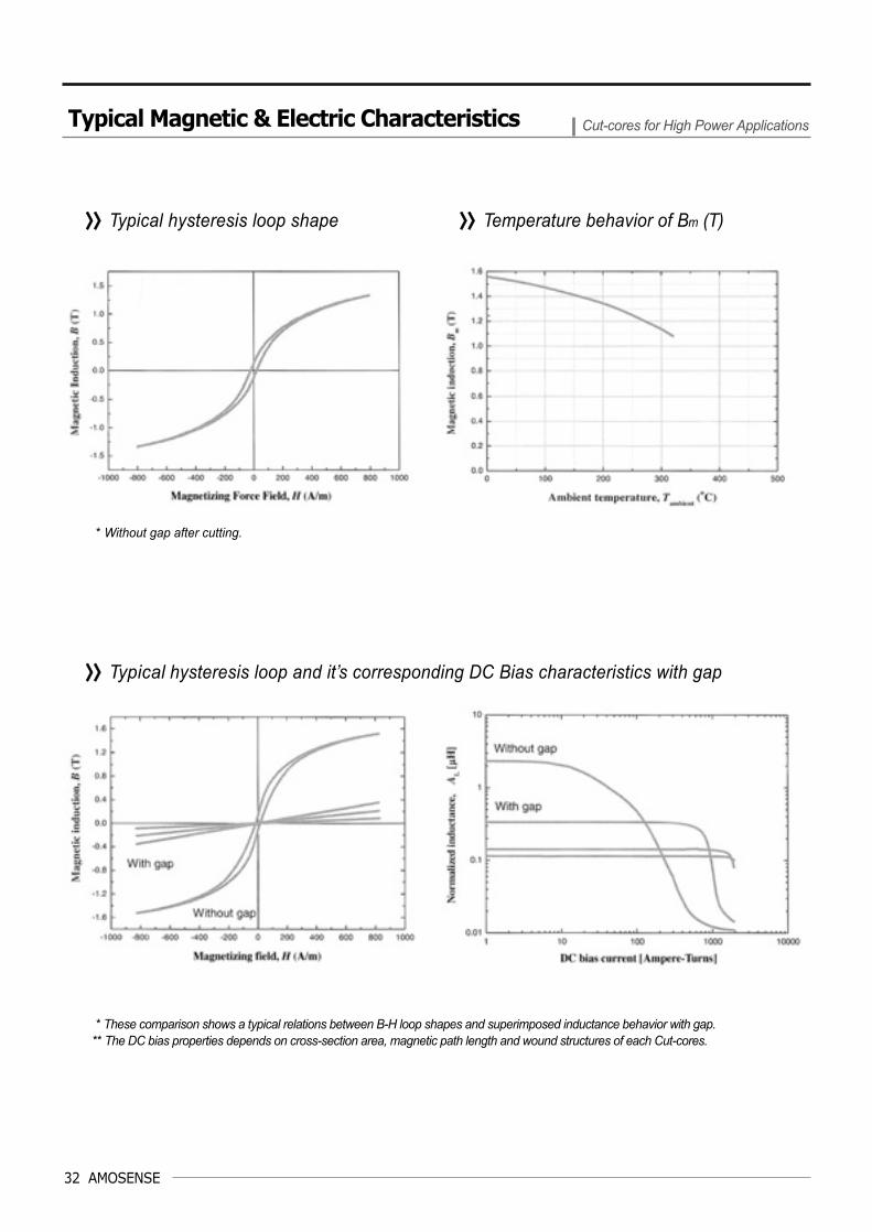
>>>> Typical hysteresis loop and it’s corresponding DC Bias characteristics with gap
>>>> Typical hysteresis loop shape >>>> Temperature behavior of Bm (T)
* These comparison shows a typical relations between B-H loop shapes and superimposed inductance behavior with gap. ** The DC bias properties depends on cross-section area, magnetic path length and wound structures of each Cut-cores.
* Without gap after cutting.
Typical Magnetic & Electric Characteristics Cut-cores for High Power Applications
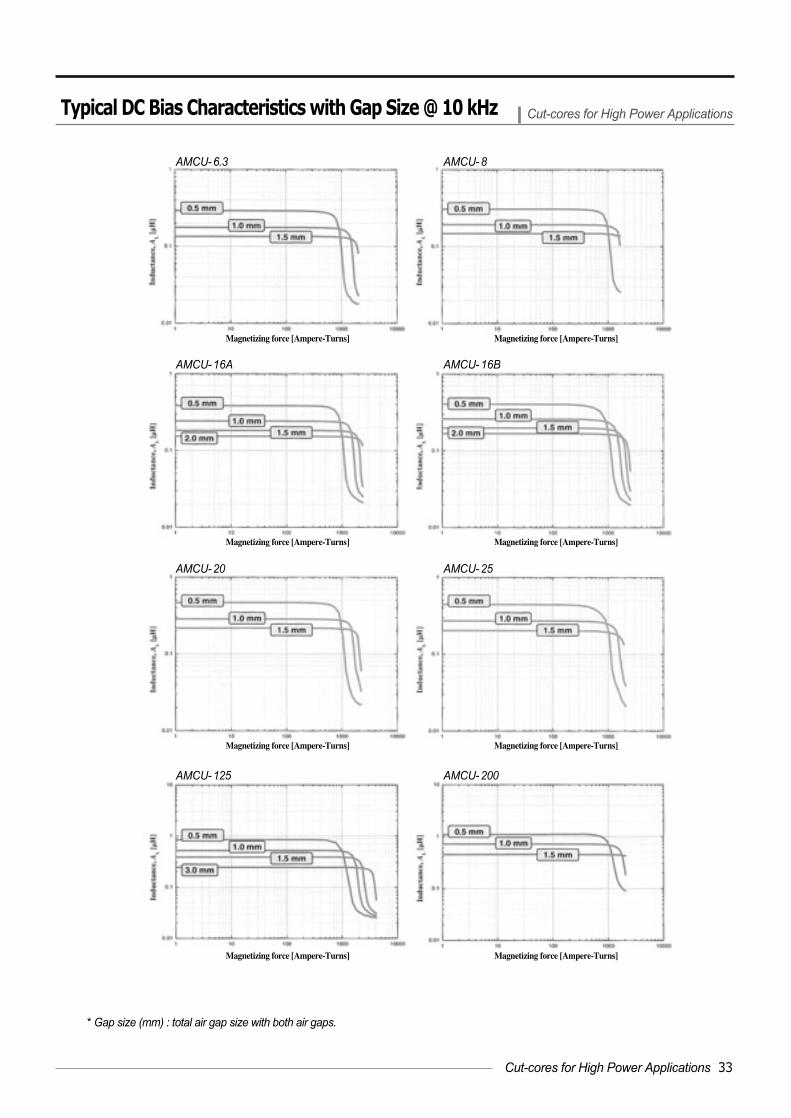
* Gap size (mm) : total air gap size with both air gaps.
Typical DC Bias Characteristics with Gap Size @ 10 kHz Cut-cores for High Power Applications
AMCU-6.3 AMCU-8
AMCU-16A AMCU-16B
AMCU-20 AMCU-25
AMCU-125
Magnetizing force [Ampere-Turns] Magnetizing force [Ampere-Turns]
Magnetizing force [Ampere-Turns] Magnetizing force [Ampere-Turns]
Magnetizing force [Ampere-Turns] Magnetizing force [Ampere-Turns]
Magnetizing force [Ampere-Turns] Magnetizing force [Ampere-Turns]
AMCU-200
Cut-cores for High Power Applications 33

34 AMOSENSE
AMOS
AMOSENSE
Low Profile Chokes
C series low-profile power inductor chokes are the ideal solutions for implementingminiature DC/DC converter for mobile products such as PDA, mobile phone, notebookcomputer and adapter, etc. Furthermore, it offers a good solutions in Automobileelectronic applications.
C-series made of iron-based amorphous alloys offer a better DC bias propertieswith lower winding turns that are not paralleled by other competing materials such asferrites, iron-powder, sendust and permalloy.
AMOSENSE launched a new class of low-profile choke series with easy winding andmore strengthened in mechanical during wound. The C-series made by iron basedamorphous alloys wiht high saturation flux density of around 1.5 T.
AMOSENSE new revised economical up-to-date technologies on low-profile C-seriesmanufacturing are based on our precise and years of experience in productiontechnology. AMOSENSE are pioneering new levels of performance by offeringengineers new acceptable low-profile power line choke cores and low-profile noisefiltering applications with excellent quality levels than ever before.
Based on customers requirement, AMOSENSE can satisfy by good designsolutions through our value added technical and manufacturing services.
Low-profile SMD and THD type is available. Miniature Magnetic shield type Good EMI performances Suitable for high density mounting Low core loss Low power consumption High withstanding voltage High mechanical strength Easy to wound
>>>> Description
>>>> Feature
DC/DC converters in PDA system AC/DC converters in adapter for mobile products DC/DC converters in mobile phone Output inductors for smaller size of DC/DC converter DC/DC converters for mobile CPU operation Single output SMPS for DC/DC converter module Multiple output SMPS for DC/DC converter module Pulse frequency modulation (PFM) integrated circuit below 10 W class Pulse width modulation (PWM) integrated circuit above 10 W class Battery charger Miniature type of automobile circuit applications
>>>> Application
Product Summary Low Profile Chokes
High Q
uality M
ag-Am
p Cores
Low P
rofileC
hokesLow
Profile
Chokes
PF
C &
Output
Choke e
Nanocrystalline
Mag-A
mp C
oreC
omm
on Mode
Chokes
Nanocrystalline
Mag-A
mp C
oreN
anocrystalline M
ag-Am
p Core
Nanocrystalline
Mag-A
mp C
ore

>>>> C Series Low Profile Choke
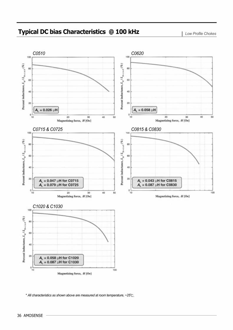
C0510 4.7 1.9 1.3 10.0 0.85 8.8 2.8 0.026 245
C0620 6.3 2.7 2.3 13.6 2.55 36.0 5.7 0.058 245
C0715 6.7 2.7 1.7 14.1 2.17 32.0 5.7 0.047 245
C0725 6.8 2.6 2.9 14.1 3.61 53.3 5.3 0.079 245
C0815 8.4 3.7 1.8 18.1 2.55 48.1 10.8 0.043 245
C0830 8.4 3.6 3.4 18.1 5.10 96.1 10.2 0.087 245
C1020 10.4 4.6 2.3 22.7 4.25 100.1 16.6 0.058 245
C1030 10.4 4.6 3.2 22.7 6.38 150.2 16.6 0.087 245
Part No.Finished Core (mm)1)
OD ID HT
Leff2) Aeff
3) Veff 4) Wa
5) AL 6) μ7)
(mm) (mm2) (mm3) (mm2) (μH)
Notes :1) The finished core dimensions shows a typical ones. Tolerance of the dimensions will be less than 0.2mm.2) Nominal values of magnetic path length. 3) Nominal values of cross-section area.4) Nominal values of volume. 5) Nominal values of window area.6) Typical values. Tolerance is ±20% of its initial AL values of each. Initial nominal inductance at 100kHz, 0.1VOSC and room temperature.7) Typical permeability.
#
Standard Core Dimensions & Specifications Low Profile Chokes
Typical Magnetic Characteristics Low Profile Chokes
Typical DC bias characteristics
DC Bias, H (Oe) Flux Density, Bm (T)
Typical core losses
Low Profile Chokes 35
36 AMOSENSE
* All characteristics as shown above are measured at room temperature, ~25.
Typical DC bias Characteristics @ 100 kHz Low Profile Chokes
C0510 C0620
C0715 & C0725
C1020 & C1030
C0815 & C0830

AMOS
AMOSENSE
Semiconductor Noise Protection Choke
AMB/AMK series are now available to reduce the spike noise in switch-mode powersupplies such as personal/industrial PSU, UPS, Telecomm/Network SMPS. This typeof noise caused by rapid changes in current and/or voltage.
In continuous mode converters, the output rectifiers have forward current flowingthrough them just prior to an instant voltage reversal across their terminals. Thiscauses a sizeable spike of reverse current to flow through the diode. This spikeusually flows through the power switch at its turn-on transition due to the reverserecovery of the output rectifier and/or catch diode. This added switching loss can bemuch more than the conduction loss of the power switch if the input voltage of thesupply is high. One method to reduce this phenomenon is to add a AMB/AMK seriesBead/Spike Killer cores in series with the output rectifier or the catch diode.
AMB/AMK series semiconductor noise suppression cores are a choke whose coreexhibits a very square hysteresis curve, so called Z-shape B-H loop, as exhibited byCo-based amorphous alloy. Chokes made with this core material have very highpermeability and quickly enter saturation, but do pass through a period of linearinductance behavior.
To use the AMB series cores, it is just to slip a suitable AMB series core to the leadsof diode or MOSFET. AMK series spike killer is often used as a single turn or with veryfew turns of wound only. AMB/AMK series semiconductor noise suppression chokecan offer an easiest way to install and effective solution to act against the source ofspike noise in PWM switch-mode power supplies.
Low loss which improve the efficiency of a switch-mode power supplies High inductance when the current crosses zero Very low saturated inductance Reduction of ripple noise and ringing Simplifies design of noise suppression circuit
>>>> Description
>>>> Feature
Softening the reverse recovery phenomena in noise suppression Protection diode from being broken by spike voltage Ringing suppression in switch-mode power supplies Limit semiconductor rectifier reverse recovery current in continuous mode converter Motor controller circuit used for MOSFET and /or bipolar transistor, BJT Ringing protection in MOSFET Time delay function for MOSFET gate trigger Bettery charger for switch-mode power supplies AC adapter for switch-mode power supplies Spike noise protection for MOSFET bridge circuit Battery charger for switch-mode power supplies AC adapter for switch-mode power supplies
>>>> Application
Product Summary Semiconductor Noise Protection Choke
Semiconductor Noise Protection Choke 37
Hig
h Q
ualit
y M
ag-A
mp
Cor
esLo
w P
rofil
eC
hoke
sA
udio
Cho
kes
PF
C &
Out
put
Cho
ke e
Nan
ocry
stal
line
Mag
-Am
p C
ore
Com
mon
Mod
eC
hoke
sN
anoc
ryst
allin
e M
ag-A
mp
Cor
eS
emic
ondu
ctor
Noi
seP
rote
ctio
n C
hoke
Noi
se S
uppr
essi
onC
ores
38 AMOSENSE
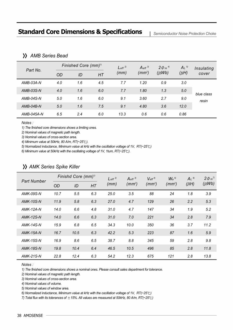
AMB-03A-N 4.0 1.6 4.5 7.7 1.20 0.9 3.0
AMB-03S-N 4.0 1.6 6.0 7.7 1.80 1.3 5.0
AMB-04S-N 5.0 1.6 6.0 9.1 3.60 2.7 9.0
AMB-04B-N 5.0 1.6 7.5 9.1 4.80 3.6 12.0
AMB-045A-N 6.5 2.4 6.0 13.3 0.6 0.6 0.86
Part No. Finished Core (mm)1)
OD ID HT
Leff2) Aeff
3) 2Φm 4) AL
5)
(mm) (mm2) (μWb) (μH)
AMK-09S-N 10.7 5.5 6.3 25.0 3.5 88 24 1.8 3.9
AMK-10S-N 11.9 5.8 6.3 27.0 4.7 129 26 2.2 5.3
AMK-12A-N 14.0 6.6 4.8 31.0 4.7 147 34 1.9 5.2
AMK-12S-N 14.0 6.6 6.3 31.0 7.0 221 34 2.8 7.9
AMK-14S-N 15.9 6.8 6.5 34.3 10.0 350 36 3.7 11.2
AMK-15A-N 16.7 10.5 6.3 42.2 5.3 223 87 1.6 5.9
AMK-15S-N 16.9 8.6 6.5 38.7 8.8 345 59 2.8 9.8
AMK-18S-N 19.8 10.4 6.4 46.5 10.5 496 85 2.8 11.8
AMK-21S-N 22.8 12.4 6.3 54.2 12.3 675 121 2.8 13.8
Part Number Finishd Core (mm)1)
OD ID HT
Leff2) Aeff
3) Veff 4) Wa
5) AL 6) 2Φm
7)
(mm) (mm2) (mm3) (mm2) (μH) (μWb)
>>>> AMB Series Bead
>>>> AMK Series Spike Killer
blue class
resin
Insulatingcover
Notes :1) The finished core dimensions shows a limiting ones. 2) Nominal values of magnetic path length. 3) Nominal values of cross-section area.4) Minimum value at 50kHz, 80 A/m, RT(~25).5) Normalized inductance, Minimum value at kHz with the oscillation voltage of 1V, RT(~25) 6) Minimum value at 50kHz with the oscillating voltage of 1V, 1turn, RT(~25).
Notes :1) The finished core dimensions shows a nominal ones. Please consult sales department for tolerance.2) Nominal values of magnetic path length. 3) Nominal values of cross-section area.4) Nominal values of volume. 5) Nominal values of window area.6) Normalized inductance, Minimum value at kHz with the oscillation voltage of 1V, RT(~25) 7) Total flux with its tolerances of ±15%. All values are measured at 50kHz, 80 A/m, RT(~25)
Standard Core Dimensions & Specifications Semiconductor Noise Protection Choke

>>>> Typical frequency dependency of inductance, AL( f )
* The frequency characteristics are measured using 1turn at room temperature, ~25.
Typical Magnetic Characteristics Semiconductor Noise Protection Choke
AMB-03A-N AMB-03S-N
AMB-04B-N AMB-04S-N
Semiconductor Noise Protection Choke 39

40 AMOSENSE
>>>> Output voltage and its current waveforms in output terminal
>>>> FET/MOSFET clamped voltage and its current waveforms
>>>> Voltage and its current waveforms in rectifying diode and catch diode
Typical Noise Suppression Effect using AMB/AMK series Noise Suppression Cores
Without AMB/AMK With AMB/AMK
Without AMB/AMK With AMB/AMK
Without AMB/AMK With AMB/AMK

AMOS
AMOSENSE
Inductive Components for Telecommunication
AMP series magnetic cores of high permeability with and/or without dc superimposedcapability are suitable for several types of pulse transformer in moderntelecommunication equipments such as integrated service digital network (ISDN), localarea network (LAN), all types of digital subscribe lines (xDSL), modem and etc.
Pulse transformer for digital communication and data line choke for signalconditioning are made of high permeability with/without dc capacity. These pulsetransformers electrically isolate the network circuit from the terminal equipment. Theminiature structure is now necessary for the pulse transformer. Normally Mn-Znferrite has been used as the magnetic core material for pulse transformers. Becauseof their low impedance resulting from low permeability, the reduction in size of thepulse transformer is difficult to achieve. If and increase in impedance is achieved byincreasing in number of turns of wound, the frequency characteristics of theimpedance become inferior, by a decrease in resonance frequency with increasinginterline capacitance. Thus, it is very difficult to satisfy the recommendation such asITU-T 1.430 standards which comes from the international telecommunication union(ITU).
AMOSENSE have been ready to supply a possible way in a smaller size of pulsetransformer using our own high quality amorphous alloys. Many types of amorphousalloys with tailored magnetic qualities have been developed with graded magneticproperties for all common ISDN interfaces such as S2M, So, Upo, Uko as well as xDSLtechnologies and data line chokes.
High permeability with dc superimposed capacity Reduce in size High impedance overall the wide-range of frequency Meet the ITU-T 1.430 standards High permeability without dc superimposed capacity Getting a suitable insertion loss in wide-range of frequency Meet the insulation requirements according to IEC 950, EN 60950, BS 601 Low core loss Lower the power consumption in telecommunication equipment
>>>> Description
>>>> Feature
So-interface- Link between the network termination (NT) and subscriber terminals (TE)- Link between the private branch exchange (PBX) and subscriber termonals (TE)
UPO/UKO-interface- Link between a local central office and the network termination (NT1)
S2M-interface- Link between a local central office and the private branch exchange (PBX)
>>>> Application
Product Summary Inductive Components for Telecommunication
AMP Series Inductive Components for Telecommunication 41
Hig
h Q
ualit
y M
ag-A
mp
Cor
esLo
w P
rofil
eC
hoke
sA
udio
Cho
kes
PF
C &
Out
put
Cho
ke e
Nan
ocry
stal
line
Mag
-Am
p C
ore
Com
mon
Mod
eC
hoke
sN
anoc
ryst
allin
e M
ag-A
mp
Cor
eN
oise
Sup
pres
sion
Cor
esIn
duct
ive
Com
pone
nts
for T
elec
omm
unic
atio
n
42 AMOSENSE
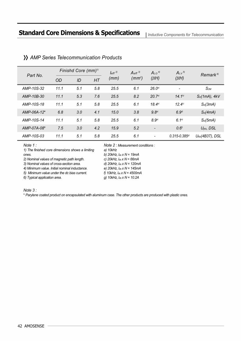
AMP-10S-32 11.1 5.1 5.8 25.5 6.1 26.0a) - S2M
AMP-10B-30 11.1 5.3 7.6 25.5 8.2 20.7a) 14.1b) So(1mA), 4kV
AMP-10S-18 11.1 5.1 5.8 25.5 6.1 18.4a) 12.4c) So(3mA)
AMP-06A-12* 6.8 3.0 4.1 15.0 3.8 9.8a) 6.9d) So(4mA)
AMP-10S-14 11.1 5.1 5.8 25.5 6.1 8.9a) 6.1e) So(5mA)
AMP-07A-08* 7.5 3.0 4.2 15.9 5.2 - 0.6f) Upo, DSL
AMP-10S-03 11.1 5.1 5.8 25.5 6.1 - 0.315-0.385g) Uko(4B3T), DSL
Part No.Finishd Core (mm)1)
OD ID HT
Ieff2) Aeff
3) ALO4) ALV
5)
(mm) (mm2) (μH) (μH)
>>>> AMP Series Telecommunication Products
Note 1 :1) The finished core dimensions shows a limitingones.2) Nominal values of magnetic path length. 3) Nominal values of cross-section area.4) Minimum value. Initial nominal inductance. 5) Minimum value under the dc bias current.6) Typical application area.
Note 3 :* Parylene coated product on encapsulated with aluminum case. The other products are produced with plastic ones.
Note 2 : Measurement conditions : a) 10kHzb) 20kHz, ldc x N = 19mAc) 20kHz, ldc x N = 66mAd) 20kHz, ldc x N = 120mA e) 20kHz, ldc x N = 145mA f) 10kHz, ldc x N = 4500mA g) 10kHz, ldc x N = 10.2A
Remark 6)
Standard Core Dimensions & Specifications Inductive Components for Telecommunication

>>>> Typical frequency & DC current dependency for So-interface pulse transformer
* All characteristics as shown above are measured at room temperature, ~25.
Typical Magnetic Characteristics Inductive Components for Telecommunication
Typical frequency properties
Typical DC bias current properties at 10 kHz
Typical impedance properties
AMP Series Inductive Components for Telecommunication 43

44 AMOSENSE
>>>> Typical frequency & DC current dependency for U-interface pulse transformer
* All characteristics as shown above are measured at room temperature, ~25.
Typical DC bias current properties at 20 kHz
Typical frequency properties Typical shapes (arb. unit)
Typical Magnetic Characteristics Inductive Components for Telecommunication