magnet-membran-dosierpumpe fmm 80 · diaphragm liquid pump with linear drive fmm 80 safety knf...
TRANSCRIPT

KNF Flodos BA_FMM80_EN_08_164464.docx
Translation of original Operating and Installation Instructions Keep for future reference!
DIAPHRAGM LIQUID PUMP WITH LINEAR
DRIVE
FMM 80
Operating and Installation Instructions
Read and observe these Oper-ating and Installation Instruc-tions! An additional letter prefixing the FMM 80 model code is a country-specific designation, with no technical relevance.
Contents Page
1. About this document ................................................................. 2 2. Use ........................................................................................... 3 3. Safety ....................................................................................... 4 4. Technical Data.......................................................................... 6 5. Assembly and function ............................................................. 8 6. Installation and connection ....................................................... 9 7. Operation ................................................................................ 12 8. Servicing ................................................................................. 17 9. Troubleshooting ...................................................................... 18 10. Spare parts and accessories .................................................. 20 11. Decontamination declaration .................................................. 21
KNF Flodos AG Wassermatte 2 6210 Sursee, Switzerland
Tel +41 (0)41 925 00 25 Fax +41 (0)41 925 00 35
www.knf-flodos.ch [email protected]
FMM 80 KP DC-P 24V
KP / TT
80
- / PMLxxxx / PLxxxx [Ch. 1]
FMM
12/24 V
DC-P

Diaphragm liquid pump with linear drive FMM 80 About this document
KNF Flodos AG BA_FMM80_EN_08_164464.docx
Translation of original Operating and Installation Instructions 2
1. About this document
1.1. Use of the Operating and Installation Instruc-tions
The Operating and Installation Instructions are part of the pump.
Forward the Operating and Installation Instructions to any
subsequent owners of the pump.
Customer-specific project pumps (pump models which begin with
"PL" or "PML") may differ from the Operating and Installation
Instructions.
In the case of project pumps, take note of any additionally
agreed specifications.
1.2. Symbols and markings
Warning
WARNING
This symbol indicates a potential danger. It also indicates the possible consequences of failure
to observe the warning. The signal word (e.g. "Warn-
ing") indicates the level of danger. Here you will see actions for avoiding the danger
and potential consequences.
Danger levels
Signal word Meaning Consequences if not observed
DANGER warns of immedi-ate danger
Consequences include death or serious injuries and/or serious property damage
WARNING warns of potential danger
Death or serious injuries and/or serious property damage are possible
CAUTION warns of a poten-tially dangerous situation
Minor injuries or damage to property are possible
Tab. 1
Other information and symbols
This indicates an activity (step) that must be carried out.
This indicates the first step of an activity to be carried out. Any
additional steps required are numbered consecutively.
This symbol indicates important information.
Project pumps

Diaphragm liquid pump with linear drive FMM 80 Use
KNF Flodos AG BA_FMM80_EN_08_164464.docx
Translation of original Operating and Installation Instructions 3
2. Use
2.1. Intended use
The pumps are intended for transferring and metering liquids.
Owner's responsibility
Only install and operate the pumps under the operating parameters
and conditions described in Chapter 4, Technical Data.
Only completely installed pumps may be taken into service.
Before transferring or metering a medium, check whether the
medium can be transferred danger-free in the specific application
case.
Before using a medium, check the compatibility of the materials of
the pump head, pump housing, diaphragm and valves with the
medium.
The temperature of the medium must lie within the permissible
temperature range (see Chapter 4).
The transferred medium should not contain particles as these can
prevent the pump from working correctly. If this cannot be ensured,
a < 50 μm filter with a sufficiently large filter area must be used
upstream of the pump.
2.2. Improper use
The pumps must not be operated in an explosive atmosphere.
For special modifications outside the standard technical specifica-
tions, please contact your KNF technical adviser.
Operating parameters and
conditions
Requirements for
transferred medium

Diaphragm liquid pump with linear drive FMM 80 Safety
KNF Flodos AG BA_FMM80_EN_08_164464.docx
Translation of original Operating and Installation Instructions 4
3. Safety
Observe the safety precautions in Chapters
6. Installation and connection and 7. Operation
The pumps are built according to the generally recognised rules of
technology and in accordance with the pertinent occupational
safety and accident prevention regulations. Nevertheless, dangers
may occur during their use which may lead to injuries to the user or
others, or to damage to the pump or other property.
Only use the pumps when they are in a good technical and proper
working order, in accordance with their intended use, observing the
safety advice within the Operating and Installation Instructions, at
all times.
Make sure that only trained and instructed personnel or specially
trained personnel work on the pumps. This especially applies to
assembly, connection and servicing work.
Make sure that all personnel have read and understood the Oper-
ating and Installation Instructions, and in particular the "Safety"
chapter.
Always ensure adherence to all pertinent accident prevention and
safety regulations when working on and operating the pump.
When transferring dangerous media, observe the safety regula-
tions for handling such media.
Always ensure adherence to all information stickers on the pumps,
such as flow direction arrows and type plates, and keep stickers in
legible condition.
All replacement parts should be properly stored and disposed of in
accordance with the applicable environmental protection regula-
tions. Ensure adherence to the pertinent national and international
regulations. This especially applies to parts contaminated with toxic
substances.
Dispose of all packaging in an environmentally-appropriate
manner. The packaging materials are recyclable.
Ensure that the old appliance is disposed of in an envi-
ronmentally-appropriate manner. Use appropriate waste
collection systems for the disposal of end-of-life equip-
ment. Used pumps contain valuable recyclable materials.
Personnel
Working in a
safety-conscious manner
Handling dangerous media
Notes
Environmental protection
Disposal

Diaphragm liquid pump with linear drive FMM 80 Safety
KNF Flodos AG BA_FMM80_EN_08_164464.docx
Translation of original Operating and Installation Instructions 5
The pumps are in accordance with the requirements of the guide-
lines 2011/65/EU (ROHS2)
The pumps conform to the safety requirements regarding electro-
magnetic compatibility in Directive 2004/108/EC.
For the purposes of the Machinery Directive 2006/42/EC, pumps
are “partly completed machinery", and are therefore to be regarded
as not ready for use. Partly completed machinery may not be
commissioned until such time as it has been determined that the
machine in which the partly completed machinery is to be assem-
bled conforms to the provisions of the Machinery Directive
2006/42/EC. The essential requirements of Annex I of Directive
2006/42/EC (general principles) are applied and observed.
The following harmonised standards are met (operation with elec-
tronic control FE Z6):
▪ EN 61000-6-3 (incl. EN 55022 / EN 55011)
The pumps must only be serviced and repaired by the relevant
KNF Customer Service team.
EU directives/standards
Customer service and repairs

Diaphragm liquid pump with linear drive FMM 80 Technical Data
KNF Flodos AG BA_FMM80_EN_08_164464.docx
Translation of original Operating and Installation Instructions 6
4. Technical Data
Pump materials
The pump type KP stands for:
Assembly Material1)
Pump head* PP
Valves/ seals EPDM
Diaphragm EPDM
Resonating diaphragm EPDM Tab. 2
The pump type TT stands for:
Assembly Material1)
Pump head* PVDF
Valves/ seals FFKM
Diaphragm PTFE coated
Resonating diaphragm FFKM Tab. 3
1) according to DIN ISO 1629 and 1043.1
* The pump head comprises an intermediate plate and a connecting plate
(Fig. 1).
Hydraulic Data FMM 80 DC-P
Parameter Value
Nominal stroke volume 80 µl 2)
Stroke volume calibration range 30 - 80 µl
Flowrate 48 ml/min3) 80 ml/min4)
Max. permitted pressure3) 1.0 bar
Flow tight in both directions >1.0 bar
Suction head >4 mWS5) Tab. 4
During the adjustment of the pump at KNF, ten consecutive strokes are
measured. The nominal stroke volume is their average value, which lays
between 79 and 81 µl.
3) Continuous operation at 10 Hz 4) Short-time operation at 16.7 Hz (max. ED 16.7 % / max. 20 minutes),
see Chapter 7.5. 5) At nominal stroke volume
Diaphragm liquid pump with linear drive FMM 80 Technical Data
KNF Flodos AG BA_FMM80_EN_08_164464.docx
Translation of original Operating and Installation Instructions 7
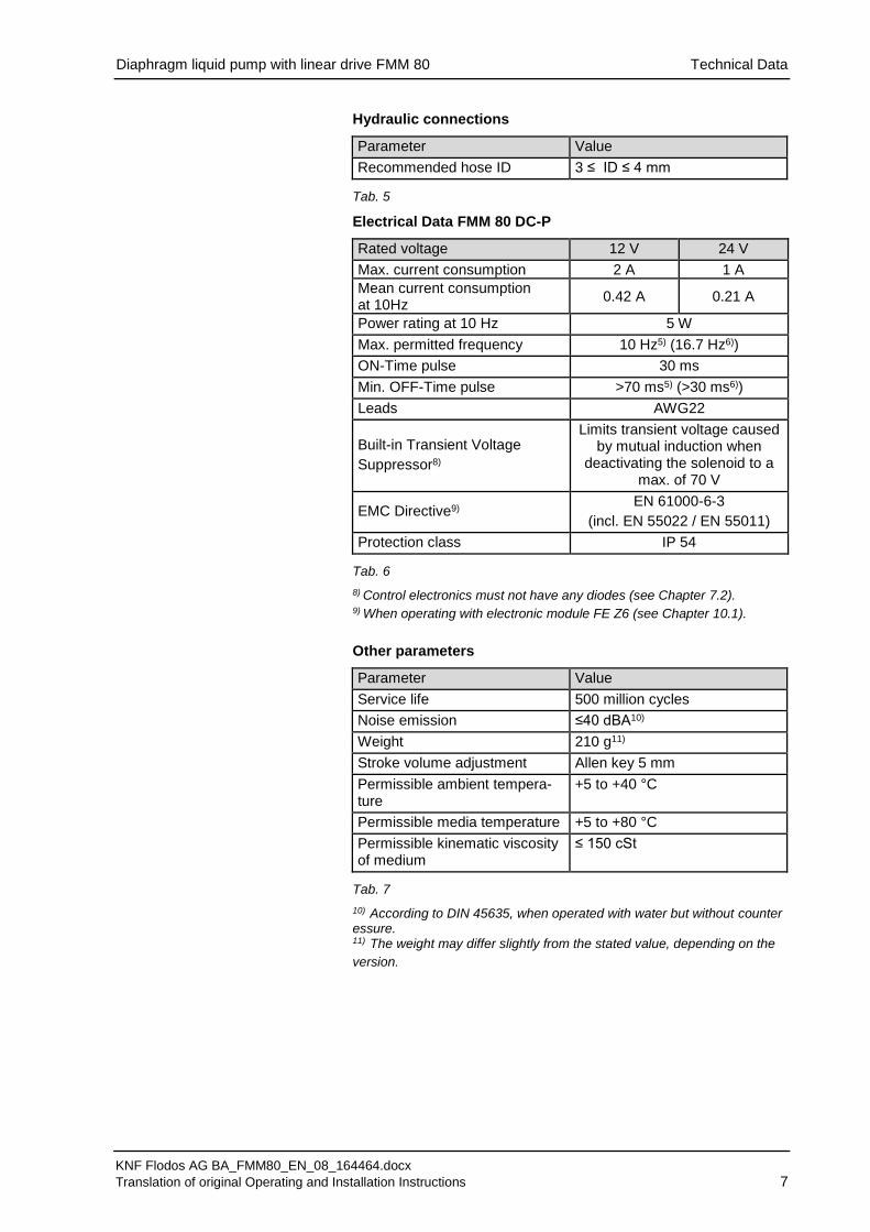
Hydraulic connections
Parameter Value
Recommended hose ID 3 ≤ ID ≤ 4 mm Tab. 5
Electrical Data FMM 80 DC-P
Rated voltage 12 V 24 V
Max. current consumption 2 A 1 A
Mean current consumption at 10Hz
0.42 A 0.21 A
Power rating at 10 Hz 5 W
Max. permitted frequency 10 Hz5) (16.7 Hz6))
ON-Time pulse 30 ms
Min. OFF-Time pulse >70 ms5) (>30 ms6))
Leads AWG22
Built-in Transient Voltage
Suppressor8)
Limits transient voltage caused by mutual induction when
deactivating the solenoid to a max. of 70 V
EMC Directive9) EN 61000-6-3
(incl. EN 55022 / EN 55011)
Protection class IP 54 Tab. 6
8) Control electronics must not have any diodes (see Chapter 7.2). 9) When operating with electronic module FE Z6 (see Chapter 10.1).
Other parameters
Parameter Value
Service life 500 million cycles
Noise emission ≤40 dBA10)
Weight 210 g11)
Stroke volume adjustment Allen key 5 mm
Permissible ambient tempera-ture
+5 to +40 °C
Permissible media temperature +5 to +80 °C
Permissible kinematic viscosity of medium
≤ 150 cSt
Tab. 7
10) According to DIN 45635, when operated with water but without counter essure. 11) The weight may differ slightly from the stated value, depending on the
version.

Diaphragm liquid pump with linear drive FMM 80 Assembly and function
KNF Flodos AG BA_FMM80_EN_08_164464.docx
Translation of original Operating and Installation Instructions 8
5. Assembly and function
Assembly
1 Outlet 2 Inlet 3 Head plate 4 Connecting plate 5 Intermediate plate 6 Pump housing 7 Solenoid coil 8 Connecting leads 9 Calibrating screw 10 Diaphragm 11 Spring 12 Armature 13 Sleeve
Fig. 1: Magnetic diaphragm metering pump FMM 80
Fig. 2: Pump assembly Supplying the magnetic coil with the specified electrical voltage
(see Chapter 4) produces a magnetic field. This magnetic field
pulls the armature (12) and the attached diaphragm (10) back to an
adjustable limit stop. This causes the diaphragm chamber to be
filled with the pumped medium via the inlet (2). In the upward
stroke, the spring tension on the diaphragm forces the medium out
of the pump head via the outlet (1). Once the upward stroke is
completed, the spring (11) pushes the diaphragm into the dia-
phragm chamber until the next pulse. This closes the suction and
pressure lines. The stroke volume of the pump can be adjusted via
the limit stop. The height of the limit stop is adjusted by turning the
calibrating screw (9).

Diaphragm liquid pump with linear drive FMM 80 Installation and connection
KNF Flodos AG BA_FMM80_EN_08_164464.docx
Translation of original Operating and Installation Instructions 9
6. Installation and connection
Install the pumps only under the operating parameters and condi-
tions described in Chapter 4 Technical Data.
Observe all safety precautions (see Chapter 3).
6.1. Installation
Before installation, store the pump at the installation location to
bring it up to ambient temperature.
Mounting dimensions (see Fig. 3)
Fig. 3: Mounting dimensions FMM 80
Make sure that the installation location is dry and the pump is
protected against water in the form of rain, spray, splashes and
drips.
Protect the pump against dust.
Protect the pump against vibration and impact.
Generally speaking, the pump can be mounted in any installa-
tion position. For maximum precision and rapid venting, install
pump in the optimum position (Fig. 4: Optimum installation po-
sition).
Fig. 4: Optimum installation position
Mounting dimensions
Installation location
Installation position

Diaphragm liquid pump with linear drive FMM 80 Installation and connection
KNF Flodos AG BA_FMM80_EN_08_164464.docx
Translation of original Operating and Installation Instructions 10
6.2. Electrical connection
Only have the pump connected by an authorized specialist.
Only have the pump connected when the power supply is
disconnected.
The electrical installation must be fitted with a device that
disconnects the magnetic coil from the mains (acc. to EN
60335-1)
When connecting the device to a power source, the relevant
norms, directives, regulations and technical standards must be
observed.
Connecting the pump
Make sure that the power supply data match the data on the
motor's type plate. The current consumption can be found on
the type plate.
The supply voltage must not deviate more than ±10% from the
specifications on the type plate.
Connect the voltage supply cables to the two pump leads.
The polarity is irrelevant.
CAUTION
Do not connect the pump to a continuous direct
voltage. Information on the control signal (see
Chapter 7).
As a consequence of the built-in transient voltage
suppressor, the special requirements for the con-
trol electronics must be observed (see Chapter
7.2).

Diaphragm liquid pump with linear drive FMM 80 Installation and connection
KNF Flodos AG BA_FMM80_EN_08_164464.docx
Translation of original Operating and Installation Instructions 11
6.3. Hydraulic connection
Only connect components to the pump that are designed to
handle the hydraulic data of the pump (see Chapter 4).
Only use hoses that are suitable for the maximum operating
pressure of the pump (see Chapter 4).
Only use hoses that are sufficiently chemically resistant to the
liquids being pumped.
The hydraulic connection can be made using hoses (Section 6.3.1)
6.3.1. Connecting the pump
Arrows on the pump head indicate the flow direction.
Remove the protective caps from the connections.
Connect the suction and pressure lines.
Keep the suction line as short as possible in order to keep the
priming process as brief as possible.
If the pump is used to build up pressure, make sure that all
transition joints between hose and pump are secure in order to
ensure that the hoses cannot come off.
Check that the hoses and transition joints are fitted correctly
and securely.
Check that the system is leak-tight.
Connected
components
Hoses
Diaphragm liquid pump with linear drive FMM 80 Operation
KNF Flodos AG BA_FMM80_EN_08_164464.docx
Translation of original Operating and Installation Instructions 12
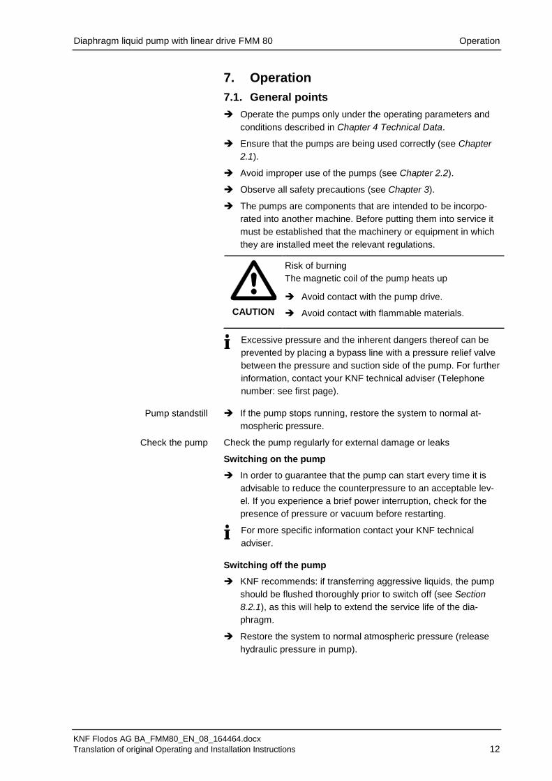
7. Operation
7.1. General points
Operate the pumps only under the operating parameters and
conditions described in Chapter 4 Technical Data.
Ensure that the pumps are being used correctly (see Chapter
2.1).
Avoid improper use of the pumps (see Chapter 2.2).
Observe all safety precautions (see Chapter 3).
The pumps are components that are intended to be incorpo-
rated into another machine. Before putting them into service it
must be established that the machinery or equipment in which
they are installed meet the relevant regulations.
CAUTION
Risk of burning
The magnetic coil of the pump heats up Avoid contact with the pump drive.
Avoid contact with flammable materials.
Excessive pressure and the inherent dangers thereof can be
prevented by placing a bypass line with a pressure relief valve
between the pressure and suction side of the pump. For further
information, contact your KNF technical adviser (Telephone
number: see first page).
If the pump stops running, restore the system to normal at-
mospheric pressure.
Check the pump regularly for external damage or leaks
Switching on the pump
In order to guarantee that the pump can start every time it is
advisable to reduce the counterpressure to an acceptable lev-
el. If you experience a brief power interruption, check for the
presence of pressure or vacuum before restarting.
For more specific information contact your KNF technical
adviser.
Switching off the pump
KNF recommends: if transferring aggressive liquids, the pump
should be flushed thoroughly prior to switch off (see Section
8.2.1), as this will help to extend the service life of the dia-
phragm.
Restore the system to normal atmospheric pressure (release
hydraulic pressure in pump).
Pump standstill
Check the pump

Diaphragm liquid pump with linear drive FMM 80 Operation
KNF Flodos AG BA_FMM80_EN_08_164464.docx
Translation of original Operating and Installation Instructions 13
7.2. Electromechanical design
The FMM 80 DC-P has a fixed transient voltage suppressor. Alter-
nating control signals cause inductive voltage spikes on the sole-
noid. The transient voltage suppressor allows a controlled dis-
charge of the mutual induction voltage generated at the solenoid to
take place, thus preventing damage to the electronic control sys-
tem. However, the circuit breaker must be able to handle voltages
of at least 70 V.
CAUTION
Whatever type of control is used (Fig. 5 and Fig. 6),
no additional freewheeling diodes may be used in the
control circuit. If used, they may adversely affect signal quality,
resulting in a reduction in precision.
1 Solenoid 2 Transient voltage suppres-
sor 3 Freewheeling diode not
permitted.
Fig. 5: Diagram – Supply reference control
Fig. 6: Diagram – Ground reference control
Freewheeling diode

Diaphragm liquid pump with linear drive FMM 80 Operation
KNF Flodos AG BA_FMM80_EN_08_164464.docx
Translation of original Operating and Installation Instructions 14
7.3. Executing single strokes
When the voltage is applied, the pump sucks in liquid. When the
voltage is removed, the previously sucked-in liquid is ejected.
For operational purposes, the suction time, i.e. the time that
the magnetic coil is energised, must be 30 ms.
Fig. 7: Control signal (pulse)
7.4. Executing several strokes
The stroke frequency can be adjusted via the voltage frequency.
Frequency range: 0 to 10 Hz5) (max. 16.7 Hz6)).
The exhaust time is at least 70ms5) in continuous operation
and at least 30ms6) in short-time operation.
5) Continuous operation 6) Short-time operation (max. ED 16.7% / max. 20 minutes), see Chapter 7.5.
Diaphragm liquid pump with linear drive FMM 80 Operation
KNF Flodos AG BA_FMM80_EN_08_164464.docx
Translation of original Operating and Installation Instructions 15
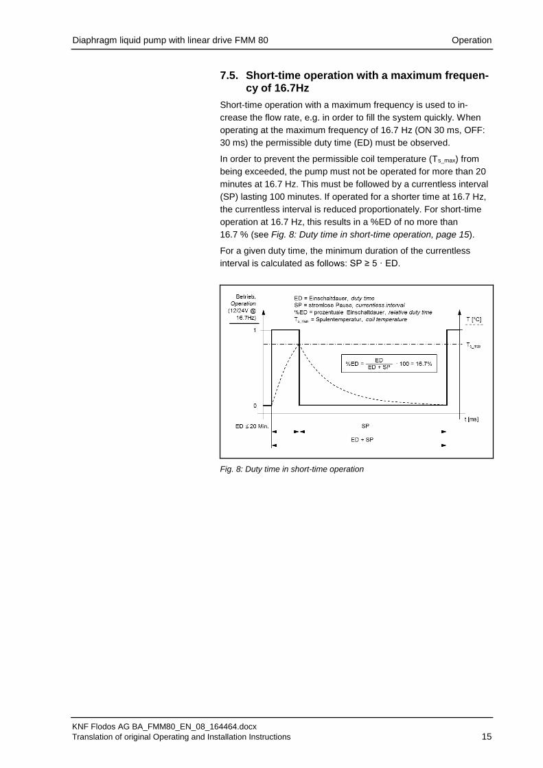
7.5. Short-time operation with a maximum frequen-cy of 16.7Hz
Short-time operation with a maximum frequency is used to in-
crease the flow rate, e.g. in order to fill the system quickly. When
operating at the maximum frequency of 16.7 Hz (ON 30 ms, OFF:
30 ms) the permissible duty time (ED) must be observed.
In order to prevent the permissible coil temperature (Ts_max) from
being exceeded, the pump must not be operated for more than 20
minutes at 16.7 Hz. This must be followed by a currentless interval
(SP) lasting 100 minutes. If operated for a shorter time at 16.7 Hz,
the currentless interval is reduced proportionately. For short-time
operation at 16.7 Hz, this results in a %ED of no more than
16.7 % (see Fig. 8: Duty time in short-time operation, page 15).
For a given duty time, the minimum duration of the currentless
interval is calculated as follows: SP ≥ 5 · ED.
Fig. 8: Duty time in short-time operation

Diaphragm liquid pump with linear drive FMM 80 Operation
KNF Flodos AG BA_FMM80_EN_08_164464.docx
Translation of original Operating and Installation Instructions 16
Fig. 9 Adjusting the stroke
7.6. Adjusting the stroke volume
The stroke volume, and thus the metering volume of the pumped
media, can be adjusted by turning the calibrating screw (see Fig. 9,
item 1) at the bottom of the pump.
Calibration range of metering volume per pump stroke: 30 – 80 μl.
A 5 mm Allen key is required to adjust the stroke.
7.7. Adjusting the flow rate
The flow rate can be adjusted via the stroke volume (Chapter 7.6)
or by means of the stroke frequency (Chapter 7.4).
For reasons of accuracy the suction time, or the energised time
(SZ), must be kept constant and the stroke frequency must be
adjusted via the exhaust time (DZ) (see Fig. 7).
The pumps are checked and set to a suction/energised time of
30 ms by KNF Flodos.

Diaphragm liquid pump with linear drive FMM 80 Servicing
KNF Flodos AG BA_FMM80_EN_08_164464.docx
Translation of original Operating and Installation Instructions 17
8. Servicing
8.1. Servicing schedule
Component Servicing interval
Pump - Regular inspection for external damage or leaks
Tab. 8
8.2. Cleaning
WARNING
Health hazard due to dangerous substances in the
pump!
Depending on the substance transferred, caustic
burns or poisoning are possible.
Wear protective clothing if necessary, e.g. pro-
tective gloves.
Flush the pump with a neutral liquid and pump
empty.
8.2.1. Flushing the pump
When transferring aggressive media, in order to extend the
service life of valves and diaphragms, KNF recommends flush-
ing the pump with air (if necessary on safety grounds: with an
inert gas) or with a neutral liquid under atmospheric conditions
for a few minutes before switching off.
8.2.2. Cleaning the pump
Where possible, wipe the solenoid and the pump head with a
dry cloth. Do not use cleaning solvents as these may corrode
plastic parts.
Information on procedure
Diaphragm liquid pump with linear drive FMM 80 Troubleshooting
KNF Flodos AG BA_FMM80_EN_08_164464.docx
Translation of original Operating and Installation Instructions 18
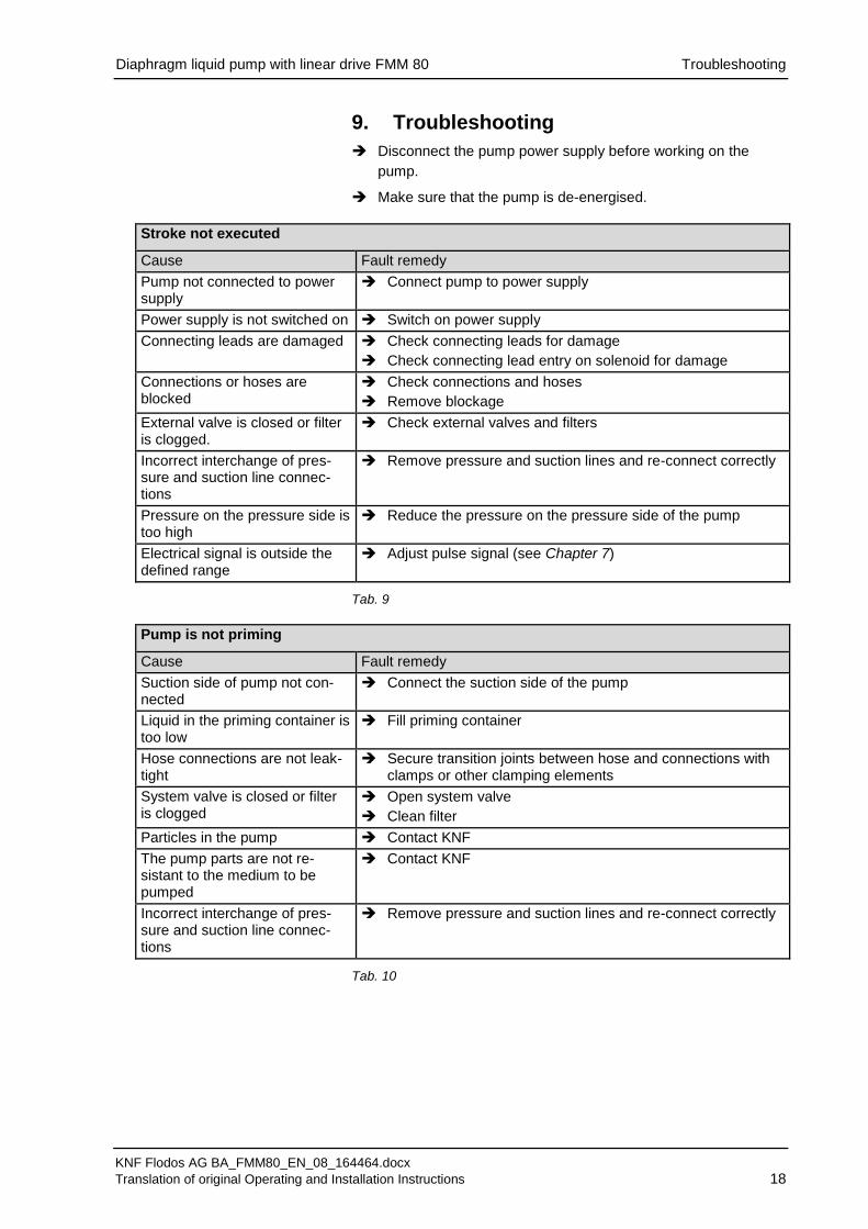
9. Troubleshooting
Disconnect the pump power supply before working on the
pump.
Make sure that the pump is de-energised.
Stroke not executed
Cause Fault remedy
Pump not connected to power supply
Connect pump to power supply
Power supply is not switched on Switch on power supply
Connecting leads are damaged Check connecting leads for damage
Check connecting lead entry on solenoid for damage
Connections or hoses are blocked
Check connections and hoses
Remove blockage
External valve is closed or filter is clogged.
Check external valves and filters
Incorrect interchange of pres-sure and suction line connec-tions
Remove pressure and suction lines and re-connect correctly
Pressure on the pressure side is too high
Reduce the pressure on the pressure side of the pump
Electrical signal is outside the defined range
Adjust pulse signal (see Chapter 7)
Tab. 9
Pump is not priming
Cause Fault remedy
Suction side of pump not con-nected
Connect the suction side of the pump
Liquid in the priming container is too low
Fill priming container
Hose connections are not leak-tight
Secure transition joints between hose and connections with clamps or other clamping elements
System valve is closed or filter is clogged
Open system valve
Clean filter
Particles in the pump Contact KNF
The pump parts are not re-sistant to the medium to be pumped
Contact KNF
Incorrect interchange of pres-sure and suction line connec-tions
Remove pressure and suction lines and re-connect correctly
Tab. 10

Diaphragm liquid pump with linear drive FMM 80 Troubleshooting
KNF Flodos AG BA_FMM80_EN_08_164464.docx
Translation of original Operating and Installation Instructions 19
Flow rate, suction head or pressure head is too low
The pump does not achieve the performance stated in the technical data or on the data sheet.
Cause Fault remedy
Components in the system connected to the suction and pressure sides, such as hoses, valves or filters, are causing too much resistance
Modify installation, check cross-sections of components
Hose connections are not leak-tight
Secure transition joints between hose and hose connectors with clamps or other clamping elements
Particles in the pump Contact KNF
Viscosity of the transferred medium is too high
Contact KNF
Incorrect interchange of pres-sure and suction line connec-tions
Remove pressure and suction lines and re-connect correctly
The pump parts are not re-sistant to the medium to be pumped
Replace the pump head with a compatible version
Tab. 11
Fault cannot be rectified
If you are unable to identify any of the above causes, please send
the pump to KNF customer service (see address on last page).
Flush the pump to clear the pump head of any hazardous or
aggressive fluids (see Section 8.2.1).
Dismantle the pump.
Clean the pump (see Section 8.2.2).
Send the pump, with completed decontamination declaration
(see Chapter 11), to KNF stating the nature of the pumped
medium.

Diaphragm liquid pump with linear drive FMM 80 Spare parts and accessories
KNF Flodos AG BA_FMM80_EN_08_164464.docx
Translation of original Operating and Installation Instructions 20
10. Spare parts and accessories
10.1. Accessories
Accessories Order No.
Starter-Kit FSK 4 165133 Tab. 12
Diaphragm liquid pump with linear drive FMM 80 Decontamination declaration
KNF Flodos AG BA_FMM80_EN_08_164464.docx
Translation of original Operating and Installation Instructions 21
11. Decontamination declaration
KNF shall only undertake to repair the pump on condition that
the customer provides certification of the transferred media
and the cleaning of the pump (decontamination declaration).
In order to send a product back use the decontamination
declaration, which either was delivered with the product or is
available on www.knf.com (Downloads).
Please fill in the pump type, serial number, pumped media and all
other required information. Send the signed form together with the
product to your KNF representative.

KNF worldwide
Please find your local KNF partners at: www.knf.com