magduo control panel engineering and commissioning …
TRANSCRIPT


MAGDUO Control Panel Engineering and Commissioning Manual
26-1649-02
ESP’s policy is one of continual improvement and the right to change a specification at any time without notice is reserved. Whilst every care has been taken to ensure that the contents of this document are correct at time of publication, ESP shall be under no liability whatsoever in respect of such contents.
Due to the complexity and inherent importance of a life risk type system, training on this equipment is essential and commissioning should only be carried out by competent persons.
ESP cannot guarantee the operation of any equipment unless all documented instructions are complied with, without variation.
E&OE.

MAGDUO Control Panel Engineering and Commissioning Manual
3
Contents
Introduction .......................................................................................................................... 5
System Design .......................................................................................................... 5 Equipment Guarantee .............................................................................................. 5 Anti Static Handling Guidelines ................................................................................ 5 Warning .................................................................................................................... 5 EMC .......................................................................................................................... 6
The MAGDUOSystem .......................................................................................................... 6
Control Panel ....................................................................................................................... 7
Mounting the Control Panel ...................................................................................... 7 Physical Dimensions ................................................................................................ 7 Power Supply Unit .................................................................................................... 8 General Assembly .................................................................................................... 9 Topology and Cabling ............................................................................................... 9 System Wiring Schematic ......................................................................................... 10 Control Panel Connections ....................................................................................... 11
Overview – 2 zone panel.. .............................................................................. 11 Overview – 4 / 8 zone panel ........................................................................... 12 USB-B ............................................................................................................. 12 Network: NET A, NET B, SCRN ..................................................................... 12 Monitored Input Wiring .................................................................................... 13 Programmable Inputs 1 & 2 ............................................................................ 13 MAGDUO Device Zones Wiring ..................................................................... 14 Conventional Device Zones Wiring ................................................................ 15 Fault Relay ...................................................................................................... 16 Fire Relay........................................................................................................ 16 Mains Input Wiring .......................................................................................... 16 Monitored Outputs 1 & 2 ................................................................................. 17 Auxiliary Power Output ................................................................................... 17 Batteries .......................................................................................................... 18 LCD Contrast .................................................................................................. 18 Write Protect / Write Enable Switch ................................................................ 19 LK1 Buzzer Link ............................................................................................. 19 MAGDUO Expansion Card ............................................................................. 20 Conventional Expansion Card ........................................................................ 20
General Operation of Control Panel .................................................................................. 21
Control Panel Front ................................................................................................. 21 LED Indication .......................................................................................................... 22 Fire Alarm Controls ................................................................................................... 24 System Controls ....................................................................................................... 24 Access Levels and Codes ........................................................................................ 23 Access Level 1 (Normal) .......................................................................................... 25 Access Level 2A (User) ............................................................................................ 26 Access Level 2B (Supervisor) .................................................................................. 28 Access Level 3 (Engineer) ........................................................................................ 33
Alarm Delays ........................................................................................................................ 57
Alarm Confirmation ............................................................................................................. 57
Introduction .............................................................................................................. 57 Zone Type ................................................................................................................ 57 Zones – Normal Operation in Communal Areas. ..................................................... 57 Zones – Confirmation Delay for Dwelling Areas. ...................................................... 58 Zones – Local or Zonal Alarm Confirmation ............................................................. 58

MAGDUO Control Panel Engineering and Commissioning Manual
26-1649-02
Installation and Commissioning ........................................................................................ 60
Installation 1st Stage ............................................................................................... 60 Installation 2nd Stage ............................................................................................... 60 Commissioning ......................................................................................................... 61 End User Training ..................................................................................................... 61 Maintenance ............................................................................................................. 61
Fault Finding ........................................................................................................................ 62
Summary of Faults.................................................................................................... 62 Finding Zone Faults .................................................................................................. 64
Advanced Connections ....................................................................................................... 65
Magnetic Door Hold Units ......................................................................................... 65 Connecting Two Panels Together ............................................................................ 66 Connecting Four Panels Together............................................................................ 67 Connecting Two TF Pro Panels & One TF V3 Panel Together ................................ 68 Peripheral Buss Connections ................................................................................... 69 External Battery Box connections............................................................................. 70
Technical Data ..................................................................................................................... 71
Control Panel Specification ...................................................................................... 71 Control Panel Ratings ............................................................................................... 71 Control Panel Fuses ................................................................................................. 72
Installation Checklist ........................................................................................................... 73
Commissioning Checklist ................................................................................................... 74
Cable Continuity and Insulation Test Results .................................................................. 75
Fire Alarm System Notice ................................................................................................... 76
Fire Alarm User Notice ........................................................................................................ 77
Engineers Notes .................................................................................................................. 78

MAGDUO Control Panel Engineering and Commissioning Manual
5
Introduction
This Manual is intended as a guide to the engineering and commissioning principles of the MAGDUO 2-wire Fire Detection and Alarm system and covers the system hardware information only.
Due to the complexity and inherent importance of a system covering a ‘Life Protection Risk’, training on this equipment is essential and commissioning should only be carried out by competent and approved persons. For further details of the availability of commissioning services, please contact your supplier.
System Design
This document does not cover Fire Alarm system design and a basic understanding is assumed.
A knowledge of BS5839: Pt 1: 2017: Fire Detection and Alarm Systems for Buildings is essential.
It is strongly recommended that a suitably qualified and competent person is consulted in connection with the Fire Alarm System design and that the entire system is commissioned in accordance with the current national standards and specifications.
Equipment Guarantee
The equipment carries no warranty unless the system is installed, commissioned and serviced in accordance with this manual and the relevant standards by a suitably qualified and competent person or organisation
Anti Static Handling Guidelines
Immediately prior to handling any PCBs or other static sensitive devices, it is essential to ensure that a personal connection to earth is made with an anti-static wrist-strap or similar apparatus.
Always handle PCBs by their sides and avoid touching any components. PCBs should also be stored in a clean dry place, which is free from vibration, dust and excessive heat and is protected from mechanical damage.
Warning
Do not attempt to install this equipment until you have fully read and understood this manual.
Failure to do so may result in damage to the equipment and could invalidate the warranty.
Technical support will not be available if the instruction manual has not been read and understood. Please have this instruction manual available whenever you call for technical support.
!
!
!
!

MAGDUO Control Panel Engineering and Commissioning Manual
26-1649-02
EMC
This equipment when installed is subject to the EMC directive 2014/108/EC. It is also subject to UK Statutory Instrument 2006 No. 3418.
To maintain EMC compliance, this system must be installed as defined within this manual. Any deviation from this renders the installer liable for any EMC problems that may occur either to the equipment or to any other equipment affected by the installation.
The MAGDUO System
The MAGDUO system is an intelligent ‘2-wire’ system utilising a conventional type cabling format. The system is classed as ‘Analogue non-addressable’ due to the architecture used within the design. All field devices including sounders can be connected to the zone via a common 2-core screened cable. The devices communicate with the control panel using the ‘MAGDUO’ data protocol.
The MAGDUO panel monitors each zone for detector head removal, device fault, ‘End of line’ fault and open or short circuit fault.
Devices or detector heads should not be removed with the zone switched on. Switch off the zone (at access level 3) before removing any devices or detector heads from that zone. Detector heads must only be removed using the correct head removal tool. Removing detector heads without using the correct tool will result in damage to the head / detector base.
Every MAGDUO device has an inbuilt ‘End of line’ signal, which may be activated as required. All setting options are configured using the DIL switches fitted to the device.
Do not use a resistor or Capacitor or any other 3rd party ‘End of line’ module for ‘End of line’.
The MAGDUO control panel also provides two monitored outputs that may be configured as conventional sounder circuits or conventional 24V monitored relay circuits, a volt free common fire relay and a volt free common fault relay. There are also two multifunction latching/non-latching inputs and one monitored input programmable with options such as ‘Class-Change’ and ‘Remote fire input’.
The MAGDUO control panel incorporates an integral power supply unit and requires 2 x 12V 3.2Ah (or 3.3Ah) batteries to provide up to 48 hour standby times. For 72 hour standby times a separate external battery box can be purchased which requires 2 x 12V 7Ah batteries. All standby times depend on the system loading (refer to Technical Data for further information). Standby battery calculations may be made using the MAGDUO Panel Battery & Loading Unit Calculation Sheet.
Unlike most conventional fire alarm systems, which require separate pairs of cables for detector zones and sounder circuits, the MAGDUO system requires one 2-core screened cable for each zone to accommodate both detection devices and sounders. Furthermore, sounders are incorporated within the detector to reduce system components and simplify installation.
The MAGDUO panels include some features described in EN54-2 as ‘optional functions with requirements’. These are:-
Output to fire alarm devices EN54-2 Clause 7.8 Output to fire protection equipment, type A EN54-2 Clause 7.10.1 Dependency on more than one alarm signal, type A (Confirmation) EN54-2 Clause 7.12.1 Delays to outputs EN54-2 Clause 7.11.1
!

MAGDUO Control Panel Engineering and Commissioning Manual
7
Zone test facility EN54-2 Clause 10 Input/output facilities These facilities are described elsewhere in this manual.
Control Panel
Mounting the Control Panel
First identify the proposed location for the control panel. Ensure that the control panel will be easily accessible and that account is taken of any subsequent work that may affect access.
The control panel should be located at the most likely point of access for the fire services. It should be mounted on a flat, vertical wall at a height where the indicators may be seen without difficulty.
Do not locate the control panel at high level where stepladders or other access equipment may be required, in spaces with restricted access, or in a position that may require access panels to be removed.
Do not locate the control panel where extremes of temperature or humidity may occur, or where there is any possibility of condensation or water ingress.
Like all electronic equipment, the control panel may be affected by extreme environmental conditions. The position selected for its installation should therefore be clean and dry, not subjected to high levels of vibration or shock and at least 2 metres away from any pager or radio transmitting equipment. Ambient temperatures should be within the range given within the Technical Data section, e.g. not directly over a radiator, heater or in direct sunlight.
In common with all microprocessor-controlled panels, the control panel may operate erratically or may be damaged if subjected to lightning induced transients. Proper earth/ground connections will greatly reduce susceptibility to this problem.
Physical Dimensions
All Panels

MAGDUO Control Panel Engineering and Commissioning Manual
26-1649-02
Power Supply Unit
The mains supply should be dedicated to the Fire Alarm Panel and should be clearly labelled ‘FIRE ALARM: DO NOT SWITCH OFF’ at all isolation points. The Fire Alarm Panel 230V AC supply requires a 3 amp un-switched fused spur with local isolation and fixed wiring between 0.75 mm
2 and 2.5 mm
2,
terminated into the fused terminals provided in the back box. The main PCB is supplied via a Switch Mode Power Supply located below the vented cover. Only the power supply provided in the unit may be used to power the control panel. Both mains termination and location of power supply are shown below.
The control panel requires standby batteries 2 x 12V 3.2Ah (or 3.4Ah) sealed lead acid batteries should be installed according to the following diagram. These are to be sited in the control panel back box using the provided clamps. The batteries should be connected in series using the connection leads supplied. See the section entitled Control Panel Connections for panel connections.
Note that the charging circuit will be in its high impedance state (approximately 3V DC) if no batteries, faulty batteries, or only one battery is connected. The full 27V DC (nominal) charging voltage should be present if the correct batteries are connected.
If the system shows a charger or battery fault on first power up, leave the system to charge the batteries for 5-6 hours.
In order to test for correct operation of the batteries, remove the mains 230V AC fuse and allow the batteries to settle from their charging voltage for approximately 5 minutes. The battery voltage should then be measured using an electronic test meter and a voltage greater than 24V DC should be seen.
Note that batteries are electrically live at all times and great care should be taken to ensure that the terminals are never presented with a short circuit. Care should be taken at all times, especially during transit, installation and normal use.
230V AC supply Switch Mode Power Supply location

MAGDUO Control Panel Engineering and Commissioning Manual
9
Batteries no longer required should be disposed of in a safe and environmentally friendly manner by the manufacturer or a suitable recycling service. They should never be incinerated or placed in normal rubbish collection facilities.
General Assembly
All Panels
Topology & Cabling
All system wiring should be installed to comply with BS 5839: Pt 1: 2017 and BS 7671 (wiring regulations) and any other standards relevant to the area or type of installation. A cable complying with the BS 5839: Pt 1: 2017 Category 1 (cables required to operate for prolonged periods during fire conditions) is required. This must be a 2-core 1.5mm
2 screened fire resistant cable (ie. FP200, Firetuff,
Firecell, Lifeline or equivalent).
Each zone requires a separate 2-core radial circuit from the control panel to the furthest point of the zone, to a maximum of 500 metres.
In order to protect against possible data corruption it is important to ensure the following points are adhered to:
1. The cable screen must be connected to earth/ground at the control panel only.
2. The cable screen must not be connected to earth/ground at any point other than the controlpanel (at the SCRN terminal provided, not at any earthing point). Do not connect thescreen to any device back box used other than those supplied by ESP.
3. The cable screen continuity must be maintained at every point of the circuit, using theterminals provided or a suitable connection block.
4. Do not use a 4-core cable as a circuit zone in and zone out, due to the possibility of datacorruption. It is essential that two 2-core screened cables are used if this is required.
Refer to the following System Wiring Schematic for further details.

MAGDUO Control Panel Engineering and Commissioning Manual
26-1649-02
System Wiring Schematic
The following schematic may prove useful as an aid to understanding the cable requirements for the system;
KEY TO SYMBOLS
MAGDUO FlexiPoint
MAGDUO FlexiPoint with Sounder
MAGDUO Manual Call Point
1 x Monitored Input, programmable as latching/non-latching, remote fire or class change. Requires a 3k3 EOL and 680 Ohm resistor to activate.
1-8 MAGDUO zones.Cabled in 2 core 1.5mm
2
Screened cable complyingwith BS 5839: Pt 1: 2017Category 1.Note: No EOL componentis required as EOL is setat the end device.
2 x Monitored Outputs, programmable as sounder or remote fire. Requires 10k EOL.
Common Fire Relay 24V 1A MAX.
Fault Relay 24V 1A MAX.
230 VAC power supply requires a dedicated supply with a local un-switched fused spur in accordance with BS5839 pt1: 2017
2 x Un-monitored Inputs programmable as latching/non-latching, remote fire or class change. Requires a volt free contact to activate.

MAGDUO Control Panel Engineering and Commissioning Manual
11
Control Panel Connections Overview- 2 zone panel
The above diagram shows the terminals for the 2 zone version of the MAGDUO panel.
Note: References to voltages are nominal values, batteries may be 3.2Ah/3.4Ah
USB-B The panel is fitted with an onboard USB-B connector. This is to provide communication via a suitable USB lead to a PC for programming of panel options using the MAGDUO configuration software.
TERMINAL DESCRIPTION
USB
USB-B USB-B CONNECTION FOR PC LINK
MONITORED I/P
MI1 + Monitored Input positive connection
MI1 - Monitored Input 0V connection
SCRN Field cable screen connection
PROG I/P 1+2
+ Programmable Input positive connection
- Programmable Input 0V connection
ZONES 1 - 2
Z + Device zone positive connection
Z - Device zone 0V connection
SCRN Field cable screen connection
FAULT RELAY
N/C Normally closed fault contact
N/O Normally open fault contact
COM Common fault contact
FIRE RELAY
N/C Normally closed fire contact
N/O Normally open fire contact
COM Common fire contact
MONITORED O/P 1+2
MO + Monitored Output positive connection
MO - Monitored Output 0V connection
SCRN Field cable screen connection
AUX SUPPLY
AUX + Aux power positive connection
AUX - Aux Power 0V connection
SCRN Field cable screen connection
BATTERY
BATT + 24V DC 3.3Ah Battery positive connection
BATT - 24V DC 3.3Ah Battery 0V connection
PSU
+V IN 24V DC Input from Switch Mode PSU
0V IN 0V DC Input from Switch Mode PSU
Earth Earth input from Switch Mode PSU

MAGDUO Control Panel Engineering and Commissioning Manual
26-1649-02
Overview – 4 / 8 zone Panel
The above diagram shows the terminals for the 4 zone / 8 zone version of the MAGDUO panel.
Note: References to voltages are nominal values, batteries may be 3.2Ah/3.4Ah
Network: NET A, NET B, SCRN
NET A & B is an RS485 buss and can communicate with ancillary equipment. Note: The RS485 Bus can only be used on 4 & 8 zone panels & will not work on 2 zone panels.
TERMINAL DESCRIPTION
USB
USB-B USB-B CONNECTION FOR PC LINK
NETWORK
NET A Peripheral Bus Connections
NET B Peripheral Bus Connections
SCRN Peripheral Bus Connections
NET A Peripheral Bus Connections
NET B Peripheral Bus Connections
SCRN Peripheral Bus Connections
MONITORED I/P
MI1 + Monitored Input positive connection
MI1 - Monitored Input 0V connection
SCRN Field cable screen connection
PROG I/P 1+2
+ Programmable Input positive connection
- Programmable Input 0V connection
ZONES 1 - 8
Z + Device zone positive connection
Z - Device zone 0V connection
SCRN Field cable screen connection
FAULT RELAY
N/C Normally closed fault contact
N/O Normally open fault contact
COM Common fault contact
FIRE RELAY
N/C Normally closed fire contact
N/O Normally open fire contact
COM Common fire contact
MONITORED O/P 1+2
MO + Monitored Output positive connection
MO - Monitored Output 0V connection
SCRN Field cable screen connection
AUX SUPPLY
AUX + Aux power positive connection
AUX - Aux Power 0V connection
SCRN Field cable screen connection
BATTERY
BATT + 24V DC 3.3Ah Battery positive connection
BATT - 24V DC 3.3Ah Battery 0V connection
PSU
+V IN 24V DC Input from Switch Mode PSU
0V IN 0V DC Input from Switch Mode PSU
Earth Earth input from Switch Mode PSU

MAGDUO Control Panel Engineering and Commissioning Manual
13
Refer to the ancillary equipment manuals for network connections. Note: Ancillary equipment e.g. repeaters connected to the network do not meet EN 54-2 requirements.
Monitored Input: MI1+, MI1-, SCRN
Maximum Voltage at contacts, 3.3 Volts. Maximum current 10mA. Monitored Input 1 may be configured to monitor for open and short circuit faults using a 3k3 EOL resistor and to activate an alarm using a 680Ω ‘firing’ resistor. It may be configured from the engineer menu to the following options:
CONTROL EVENT SILENCE ALARMS DISABLEMENT DISABLE SOUNDERS
RESET SYSTEM DISABLE REM FIRE
SOUND ALARMS DISABLE SNDR/REM FIRE
SILENCE BUZZER DISABLE BUZZER
REMOTE FIRE EVENT REMOTE FIRE - FULL DAY/NIGHT MODE INPUT ON
REM FIRE, NO RELAY INPUT OFF
TECHNICAL EVENT LATCH INPUT NOT USED INPUT OFF
NON-LATCH
Monitored Input 1 is an ancillary function and is not required by EN 54-2.
Programmable Inputs 1 and 2:
Maximum Voltage at contacts, 3.3 Volts. Maximum current 10mA. Inputs 1-2 are Un-monitored and require a normally closed contact to operate. They may be configured from the engineer menu to the following options:
CONTROL EVENT SILENCE ALARMS DISABLEMENT DISABLE SOUNDERS
RESET SYSTEM DISABLE REM FIRE
SOUND ALARMS DISABLE SNDR/REM FIRE
SILENCE BUZZER DISABLE BUZZER
REMOTE FIRE EVENT REMOTE FIRE - FULL DAY/NIGHT MODE INPUT ON
REM FIRE, NO RELAY INPUT OFF
TECHNICAL EVENT LATCH INPUT NOT USED INPUT OFF
NON-LATCH
ON BOARD PCB FIELD CONNECTIONS
MI1 -
MI1 +
3k3 EOL
SCREEN SCREEN
680Ω
N/O CONTACT
ON BOARD PCB FIELD CONNECTIONS
1 -
1 +
NO CONTACT

MAGDUO Control Panel Engineering and Commissioning Manual
26-1649-02
Programmable Inputs 1 & 2 are ancillary functions and are not required by EN 54-2 Caution – the use of an input to disable the buzzer does not meet EN54-2
MAGDUO Device Zones: Z1 - Z8:
Each zone requires a separate 2-core radial circuit from the control panel to the furthest point of the zone, to a maximum of 500 metres.
In order to protect against possible data corruption it is important to ensure the following points are adhered to:
1. The cable screen must be connected to the SCRN terminal at the control panel only.
2. The cable screen must not be connected to earth/ground at any point other than the controlpanel (at the SCRN terminal provided, not at any earthing point). Do not connect thescreen to any device back box used other than those supplied by ESP.
3. The cable screen continuity must be maintained at every point of the circuit, using theterminals provided or a suitable connection block.
4. Do not use a 4-core cable as a circuit zone in and zone out, due to the possibility of datacorruption. It is essential that two 2-core screened cables are used if this is required.
No EOL resistor or unit should be fitted to terminate the cable, this function is performed via DIL switch 1 on the last device.
If a zone is NOT used it MUST be switched off using the zone status menu in the engineers programming options.
MAXIMUM NUMBER OF DEVICES PER ZONE
Must not exceed 32 devices dependant on Device Loading Units (DLUs) not exceeding the stated maximum loading. To ensure the maximum loading is not exceeded, use the MAGDUO Panel Battery & Loading Unit Calculation Sheet.
ON BOARD PCB FIELD CONNECTIONS
Z1 -
Z1 + NO EOL REQ.
USE SW1
SCREEN
SCREEN
SCREEN
MAGDUO Control Panel Engineering and Commissioning Manual
15
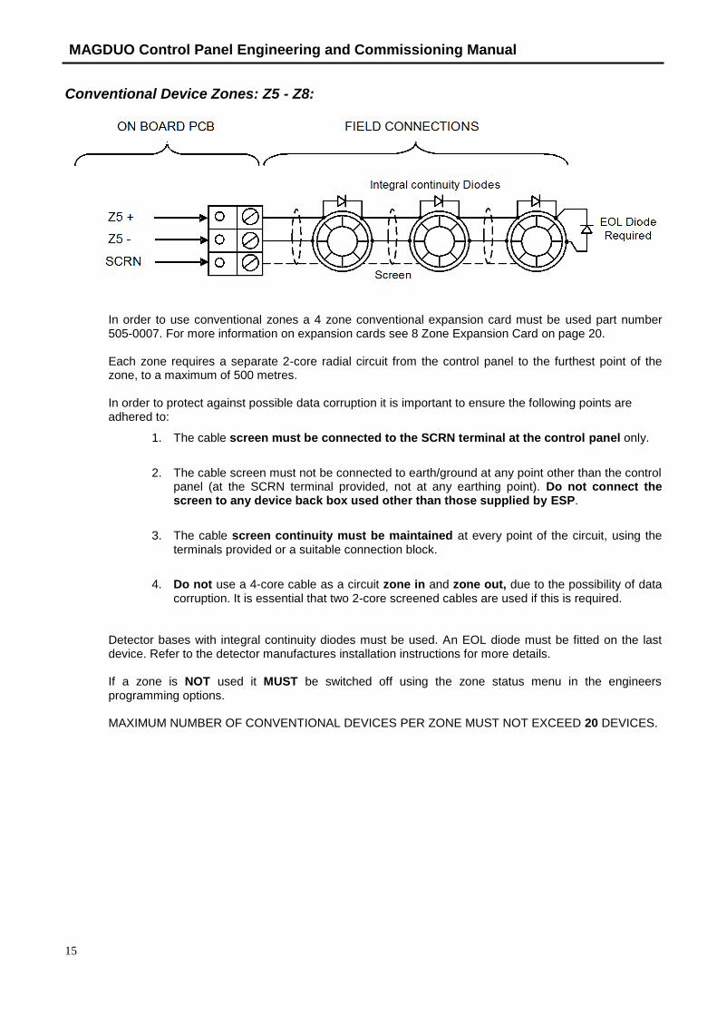
Conventional Device Zones: Z5 - Z8:
In order to use conventional zones a 4 zone conventional expansion card must be used part number 505-0007. For more information on expansion cards see 8 Zone Expansion Card on page 20.
Each zone requires a separate 2-core radial circuit from the control panel to the furthest point of the zone, to a maximum of 500 metres.
In order to protect against possible data corruption it is important to ensure the following points are adhered to:
1. The cable screen must be connected to the SCRN terminal at the control panel only.
2. The cable screen must not be connected to earth/ground at any point other than the controlpanel (at the SCRN terminal provided, not at any earthing point). Do not connect thescreen to any device back box used other than those supplied by ESP.
3. The cable screen continuity must be maintained at every point of the circuit, using theterminals provided or a suitable connection block.
4. Do not use a 4-core cable as a circuit zone in and zone out, due to the possibility of datacorruption. It is essential that two 2-core screened cables are used if this is required.
Detector bases with integral continuity diodes must be used. An EOL diode must be fitted on the last device. Refer to the detector manufactures installation instructions for more details.
If a zone is NOT used it MUST be switched off using the zone status menu in the engineers programming options.
MAXIMUM NUMBER OF CONVENTIONAL DEVICES PER ZONE MUST NOT EXCEED 20 DEVICES.
MAGDUO Control Panel Engineering and Commissioning Manual
26-1649-02
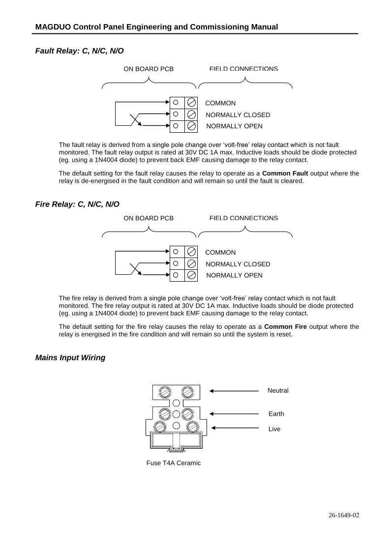
Fault Relay: C, N/C, N/O
The fault relay is derived from a single pole change over ‘volt-free’ relay contact which is not fault monitored. The fault relay output is rated at 30V DC 1A max. Inductive loads should be diode protected (eg. using a 1N4004 diode) to prevent back EMF causing damage to the relay contact.
The default setting for the fault relay causes the relay to operate as a Common Fault output where the relay is de-energised in the fault condition and will remain so until the fault is cleared.
Fire Relay: C, N/C, N/O
The fire relay is derived from a single pole change over ‘volt-free’ relay contact which is not fault monitored. The fire relay output is rated at 30V DC 1A max. Inductive loads should be diode protected (eg. using a 1N4004 diode) to prevent back EMF causing damage to the relay contact.
The default setting for the fire relay causes the relay to operate as a Common Fire output where the relay is energised in the fire condition and will remain so until the system is reset.
Mains Input Wiring
ON BOARD PCB FIELD CONNECTIONS
COMMON
NORMALLY CLOSED
NORMALLY OPEN
ON BOARD PCB FIELD CONNECTIONS
COMMON
NORMALLY CLOSED
NORMALLY OPEN
Neutral
Earth
Live
Fuse T4A Ceramic

MAGDUO Control Panel Engineering and Commissioning Manual
17
Monitored Outputs 1 and 2: MO+, MO-, SCRN
Outputs 1 and 2 are monitored circuits which may be configured to monitor for open and short circuit faults with a 10k EOL resistor.
The default setting for outputs 1 and 2 cause the circuits to operate as Common Fire Sounder Circuits, where the outputs step up to nominally 28V DC in the alarm condition. Various other states listed below may also be set from the engineers menu. The maximum output current for each output is 250mA for a 2 – 4 zone panel, 200mA for an 8 zone panel. These outputs are protected by a 300 mA trip polyfuse.
OUTPUT TYPE REMOTE SOUNDER
REMOTE FIRE
OFF
Auxiliary Power: AUX+, AUX-, SCRN
An auxiliary nominal 24V DC power supply is available to power ancillary devices requiring up to 30V DC.
Note: The auxiliary power supply output will be approximately 30-31V DC when the panel is running from a mains supply and between 22 and 27V when running from the batteries in a mains failure condition.
The maximum output current is 250mA. The Auxiliary Power is protected by a 300 mA trip polyfuse fuse.
It is suggested that additional Power Supply Units be installed to provide power for additional loads.
ON BOARD PCB FIELD CONNECTIONS
MO -
MO+ + _
+ _
10k EOL
SCREEN SCREEN SCREEN
ON BOARD PCB FIELD CONNECTIONS
AUX -
AUX + 30V DC LOAD
SCREEN SCREEN

MAGDUO Control Panel Engineering and Commissioning Manual
26-1649-02
Battery: BAT+, BAT-
Terminals are supplied to connect and charge standby batteries. The charging circuit has been designed to charge 2 x 12V DC 3.2Ah,3.3Ah or 3.4Ah sealed lead acid batteries. Batteries should be connected in series as per the diagram.
For extended backup times an external battery box can be purchased from ESP. This includes extended battery connection leads. This requires 2 x 12V 7.0Ah – 7.2Ah batteries. When using the external battery box the internal panel batteries must be removed.
LCD Contrast Note : 4 Zone / 8 Zone Panel version shown
The LCD contrast may be adjusted by rotating the screw on the variable resistor, located in the upper right hand corner of the main PCB.
+ -
+ - BAT +
BAT -

MAGDUO Control Panel Engineering and Commissioning Manual
19
Write Protect / Write Enable Switch Note: 4 Zone / 8 Zone Panel version shown
The write protect / write enable switch is a two position switch which is normally set to stop options in the engineer menu from being inadvertently changed.
ONSwitch in
OFF position
Write Protect Mode:
In the OFF position, as shown (left), engineering options may be viewed
but no changes made.
ONSwitch in
ON position
Write Enable Mode:
If changes are to be made, this switch needs to be in the ON
position as shown (left).
If the switch is left ON whilst the panel is not in engineer mode a
system fault will be reported.
LK1 Buzzer Link
Linking out LK1 will disable the panel buzzer. The buzzer will remain disabled whilst the link is in place. Warning – To comply with EN54 and BS5839: Pt1: 2017 this link must be left OPEN.
LK1

MAGDUO Control Panel Engineering and Commissioning Manual
26-1649-02
Expansion Cards
There are two expansion card options available for the MAGDUO4. Part number MAGDUOZC4 will provide 4 additional MAGDUO zones and part number MAGDUOCC4 will provide an additional 4 conventional zones.
The zone expansion card provides an additional 4 MAGDUO zones which converts a MAGDUO4 panel to an 8 zone panel.
A MAGDUO4 panel fitted with the conventional expansion card would have zones 1 to 4 as MAGDUO zones and zones 5 to 8 as conventional zones.
The MAGDUO8 contains an 8 zone PCB. This will already have been set up in the factory and programming options for the extra zones will be enabled.
The MAGDUO2 is not compatible with the expansion cards.
Expansion cards purchased separately will have the interface cable and mounting screws included in the kit.
Note: conventional zones cannot distinguish between smoke or MCP fire signals.
There is a connection using a ribbon cable from the connector labelled ‘Ribbon Cable to CIE’ on the expansion card to the connector labelled “Expansion Connector” on the rear of the CIE PCB. The ribbon cable has a ferrite fitted at one end. The end with the ferrite must be connected to the CIE.

MAGDUO Control Panel Engineering and Commissioning Manual
21
General Operation of Control Panel Control Panel Front Note : 4 Zone / 8 Zone Panel version shown
General Indication LEDs
Control Panel Information Window
Zonal Indication LEDs Fire Alarm Controls / Controls
Enabled Keyswitch
System Indication LEDs
System Controls

MAGDUO Control Panel Engineering and Commissioning Manual
26-1649-02
LED Indication Note : 4 Zone / 8 Zone Panel version shown
The operation of the LED indication on the front of the control panel is described below. The LED indication on the panel can also be confirmed by checking the message displayed in the panel information screen or by accessing the relevant event log from the panel menu.
Description Colour State Reason
FIRE Red Continuous The control panel is in the fire state. Other indicators will show the origin.
FAULT Yellow Continuous The control panel is in the fault state. Other indicators will show the origin.
DISABLED Yellow Continuous This indicates that a disablement action is in place. Enable all devices / actions to clear.
TEST Yellow Continuous This indicates that a test routine is in place. End all tests to clear.
POWER Green Continuous This indicates that power is being supplied to the control panel from either the 230V AC mains supply, or the standby batteries.
‘ZONE 1-8’ Red Continuous A Detector or Manual Call Point in the zone indicated is in the alarm state and sending an alarm signal to the panel.
SYSTEM FAULT Yellow Continuous
Flashing
The system Fault LED indicates the presence of a processor or a checksum error. Power the system down to clear, reprogram all settings and test the system.
This LED will also be illuminated if the ‘write protect / write enable’ switch is left on whilst the system is not in the engineer menu.
POWER FAULT Yellow Flashing
Continuous
A mains supply fault has been detected (check for a 230V AC supply on the incoming AC terminals).
A battery fault has been detected (check batteries and inline battery fuse).
EARTH FAULT Yellow Flashing An earth fault has been detected where a path exists from the circuit wiring to earth. Remove circuits one at a time to discover which one, and then rectify.
ZONE Yellow Flashing
Continuous
A fault condition is present on one of the zones or on a device connected to that zone.
A device or an action associated with a zone has been disabled.

MAGDUO Control Panel Engineering and Commissioning Manual
23
During a system fault, dependent upon what caused the fault, all relays will be off, all zones will be powered down, the zone, power fault and disabled LEDs will be on continuously. If any output is set to sounder then the Sounder LED will also be on continuously.
To recover from this, the panel should be powered down for approximately 2 minutes and then re-powered. This should be done by a competent person. If the panel appears to be operational, then a reset will clear the fault.
The only exception to this is the write enable switch. In access levels 1, 2A and 2B, if the switch is on, a system fault will be indicated on the LEDs and display. The fault relay will be off (to indicate a fault condition). It has no effect on the operation of the panel and serves as a reminder to the Engineer to switch off write enable before leaving the panel.
If the display is blank and no LEDs are showing, then either the unit is not powered, or the mains has failed and the batteries are lower than 21V. To recover from the low battery shut-off, power down completely and check that the batteries are no lower than 21V and then power up the system.
If the batteries are lower than 21V then they should be replaced or monitored during initial charging to ensure they recharge correctly. This could take several hours.
If the batteries are below 18V they should be replaced as they will have lost much of their capacity and are unlikely to recover. This could leave the system with no power under mains fail conditions.
ZONE SOUNDERS
Yellow
Flashing
Continuous
A fault condition is present on a MAGDUO zone circuit.
A device or an action associated with the zone sounder circuits has been disabled.
FIRE OUTPUTS Yellow Flashing
Continuous
A fault condition is present on the monitored fire circuit.
A device or an action associated with the monitored fire circuit has been disabled.
SOUNDER OUTPUTS Yellow
Flashing
Continuous
A fault condition is present on a monitored sounder circuit.
A device or an action associated with the monitored sounder circuits has been disabled.
DAY MODE Yellow Continuous The system has gone into the less sensitive day
mode as programmed.
SERVICE Yellow
Flashing
Continuous
The pre-programmed weekly test is due.
The pre-programmed service interval has expired and a routine maintenance check is due.
DELAY Yellow Continuous An action has been setup which utilises a
programmed delay.
ALARMS Yellow
Flashing
Continuous
The alarm sounders have been activated.
The alarm sounders have been silenced whilst operating, and the system is awaiting a reset.
BUZZER SILENCED Yellow
Continuous The control panel buzzer has been silenced whilst operating and will stay silenced until another fault or relevant action occurs.

MAGDUO Control Panel Engineering and Commissioning Manual
26-1649-02
Fire Alarm Controls Note : 4 Zone / 8 Zone Panel version shown
The main Fire Alarm Controls may be enabled by turning the key switch to the controls enabled position to go from access level 1 to AL2A, or by entering a valid access code to all modes above AL1. Access levels can only be entered from AL1, except from AL3A to AL3B where only the right hand side panel need be removed and the write enable switch turned on to enter AL3B from AL3A.
System Controls Note : 4 Zone / 8 Zone Panel version shown
A context-driven, cursor highlighted-selection menu system is used to navigate around the menu system, automatically prompting you with the relevant options for your Access Level and system status.
The menus may be navigated in one of two ways as required:
1. Use the UP / DOWN keys to move the highlighted selection andpress ENTER to select the chosen one.
2. Enter the desired option number and press ENTER to select it.
Press the ESC key to exit to the previous menu.
Access Levels and Codes
The menu system is divided into four access levels in order to allow access to only those who require it. For simple indication, the status of the Controls Enabled light will show the level selected as follows;
Access Level Description Controls Enabled LED
Key Operation
1 – NORM Normal OFF N/A
2A – 1111 User ON YES
2B – 2222 Supervisor SLOW FLASH NO
3A – 3333 Engineer FAST FLASH NO
3B – 3333 Engineer FAST FLASH NO
Access to the menu system requires either the operation of the enable controls key for access to Access Level 2A (User), or the correct entry of the relevant code for access to all other levels, in order to protect against unauthorised access to the system. The codes may be changed using the relevant panel menu or via the MAGDUO software.
To enter Engineer Access Level 3B, remove the right hand cover and move the write enable switch to the ON position. Remember to put the switch back to the OFF position before leaving Engineer Level.
MAGDUO Control Panel Engineering and Commissioning Manual
25
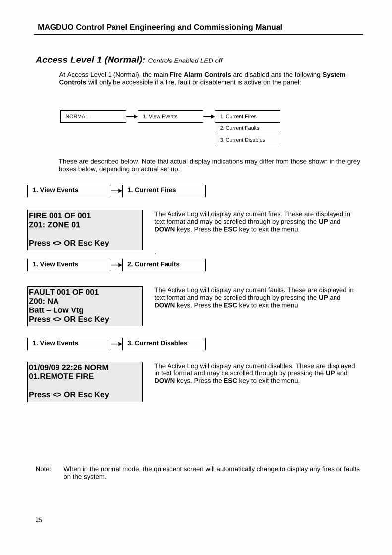
Access Level 1 (Normal): Controls Enabled LED off
At Access Level 1 (Normal), the main Fire Alarm Controls are disabled and the following System Controls will only be accessible if a fire, fault or disablement is active on the panel:
These are described below. Note that actual display indications may differ from those shown in the grey boxes below, depending on actual set up.
The Active Log will display any current fires. These are displayed in text format and may be scrolled through by pressing the UP and DOWN keys. Press the ESC key to exit the menu.
.
The Active Log will display any current faults. These are displayed in text format and may be scrolled through by pressing the UP and DOWN keys. Press the ESC key to exit the menu
The Active Log will display any current disables. These are displayed in text format and may be scrolled through by pressing the UP and DOWN keys. Press the ESC key to exit the menu.
Note: When in the normal mode, the quiescent screen will automatically change to display any fires or faults on the system.
NORMAL 1. View Events 1. Current Fires
2. Current Faults
3. Current Disables
1. View Events 1. Current Fires
1. View Events 2. Current Faults
1. View Events 3. Current Disables
FIRE 001 OF 001 Z01: ZONE 01
Press <> OR Esc Key
FAULT 001 OF 001 Z00: NA Batt – Low Vtg Press <> OR Esc Key
01/09/09 22:26 NORM 01.REMOTE FIRE
Press <> OR Esc Key

MAGDUO Control Panel Engineering and Commissioning Manual
26-1649-02
Access Level 2A (User): Enable Controls LED on
At Access Level 2A (User), the main Fire Alarm Controls are enabled and the following System Controls are accessible:
These are described below. Note that actual display indications may differ from those shown in the grey boxes below, depending on actual set up.
The Active Log will display any current fires. These are displayed in text format and may be scrolled through by pressing the UP and DOWN keys. Press the ESC key to exit the menu.
The Active Log will display any current faults. These are displayed in text format and may be scrolled through by pressing the UP and DOWN keys. Press the ESC key to exit the menu.
The Active Log will display any current disables. These are displayed in text format and may be scrolled through by pressing the UP and DOWN keys. Press the ESC key to exit the menu.
USER (1111) 1. View Current Events 1. Current Fires
2. Current Faults
3. Current Disables
4. Current Warnings
1. Test Cntrls & Display 2. Test Modes 1. Test LCD Display
2. Test LEDs
3. Test Buzzer
4. Test Keyboard
1. View Current Events 1. Current Fires
1. View Current Events 2. Current Faults
1. View Current Events 3. Current Disables
FIRE 001 OF 001 Z01: ZONE 01
Press <> OR Esc Key
FAULT 001 OF 001 Z00: NA Batt – Low Vtg Press <> OR Esc Key
01/09/09 22:26 USER 01.REMOTE FIRE
Press <> OR Esc Key
MAGDUO Control Panel Engineering and Commissioning Manual
27
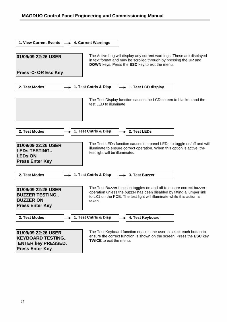
The Active Log will display any current warnings. These are displayed in text format and may be scrolled through by pressing the UP and DOWN keys. Press the ESC key to exit the menu.
The Test Display function causes the LCD screen to blacken and the test LED to illuminate.
The Test LEDs function causes the panel LEDs to toggle on/off and will illuminate to ensure correct operation. When this option is active, the test light will be illuminated.
The Test Buzzer function toggles on and off to ensure correct buzzer operation unless the buzzer has been disabled by fitting a jumper link to LK1 on the PCB. The test light will illuminate while this action is taken.
The Test Keyboard function enables the user to select each button to ensure the correct function is shown on the screen. Press the ESC key TWICE to exit the menu.
1. View Current Events 4. Current Warnings
2. Test Modes 1. Test Cntrls & Disp 1. Test LCD display
2. Test Modes 1. Test Cntrls & Disp 2. Test LEDs
2. Test Modes 1. Test Cntrls & Disp 3. Test Buzzer
2. Test Modes 1. Test Cntrls & Disp 4. Test Keyboard
01/09/09 22:26 USER
Press <> OR Esc Key
01/09/09 22:26 USER LEDs TESTING.. LEDs ON Press Enter Key
01/09/09 22:26 USER BUZZER TESTING.. BUZZER ON Press Enter Key
01/09/09 22:26 USER KEYBOARD TESTING.. ENTER key PRESSED. Press Enter Key
MAGDUO Control Panel Engineering and Commissioning Manual
26-1649-02
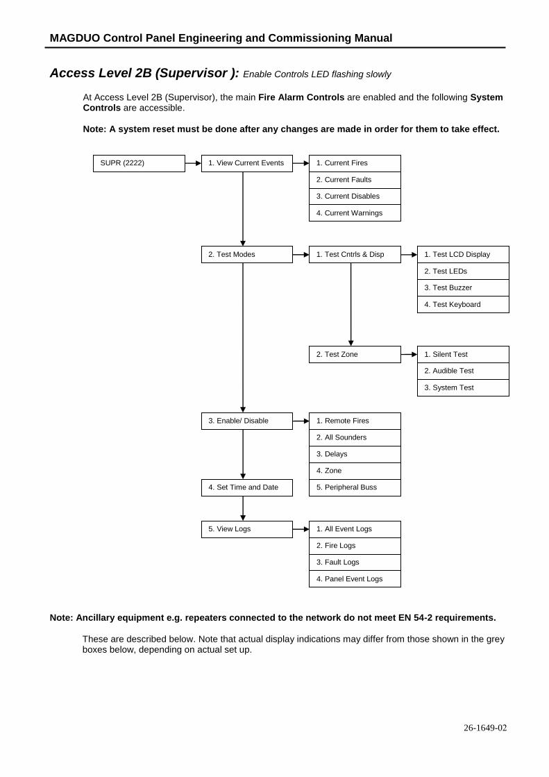
Access Level 2B (Supervisor ): Enable Controls LED flashing slowly
At Access Level 2B (Supervisor), the main Fire Alarm Controls are enabled and the following System Controls are accessible.
Note: A system reset must be done after any changes are made in order for them to take effect.
Note: Ancillary equipment e.g. repeaters connected to the network do not meet EN 54-2 requirements.
These are described below. Note that actual display indications may differ from those shown in the grey boxes below, depending on actual set up.
SUPR (2222) 1. View Current Events 1. Current Fires
2. Current Faults
3. Enable/ Disable 1. Remote Fires
2. All Sounders
3. Delays
4. Zone
5. Peripheral Buss4. Set Time and Date
5. View Logs 1. All Event Logs
2. Fire Logs
3. Fault Logs
4. Panel Event Logs
3. Current Disables
4. Current Warnings
1. Test Cntrls & Disp
2. Test Zone
2. Test Modes 1. Test LCD Display
2. Test LEDs
3. Test Buzzer
4. Test Keyboard
1. Silent Test
2. Audible Test
3. System Test

MAGDUO Control Panel Engineering and Commissioning Manual
29
The Active Log will display any current fires. These are displayed in text format and may be scrolled through by pressing the UP and DOWN keys. Press the ESC key to exit the menu.
.
The Active Log will display any current faults. These are displayed in text format and may be scrolled through by pressing the UP and DOWN keys. Press the ESC key to exit the menu.
The Active Log will display any current disables. These are displayed in text format and may be scrolled through by pressing the UP and DOWN keys. Press the ESC key to exit the menu.
The Active Log will display any current warnings. These are displayed in text format and may be scrolled through by pressing the UP and DOWN keys. Press the ESC key to exit the menu.
The Test Display function causes the LCD screen to blacken and the test LED to illuminate.
The Test LEDs function causes the panel LEDs to toggle on/off to test for correct operation. When this option is active, the test light will be illuminated.
1. View Current Events 2. Current Faults
1. View Current Events 3. Current Disables
1. View Current Events 4. Current Warnings
2. Test Modes 1. Test Cntrls & Disp 1. Test LCD display
2. Test Modes 1. Test Cntrls & Disp 2. Test LEDs
FIRE 001 OF 001 Z01: ZONE 01
Press <> OR Esc Key
FAULT 001 OF 001 Z00: NA Batt – Low Vtg Press <> OR Esc Key
01/09/09 22:26 SUPR 01.REMOTE FIRE
Press <> OR Esc Key
01/09/09 22:26 SUPR
Press <> OR Esc Key
01/09/09 22:26 SUPR LEDs TESTING.. LEDs ON Press Enter Key
1. View Current Events 1. Current Fires

MAGDUO Control Panel Engineering and Commissioning Manual
26-1649-02
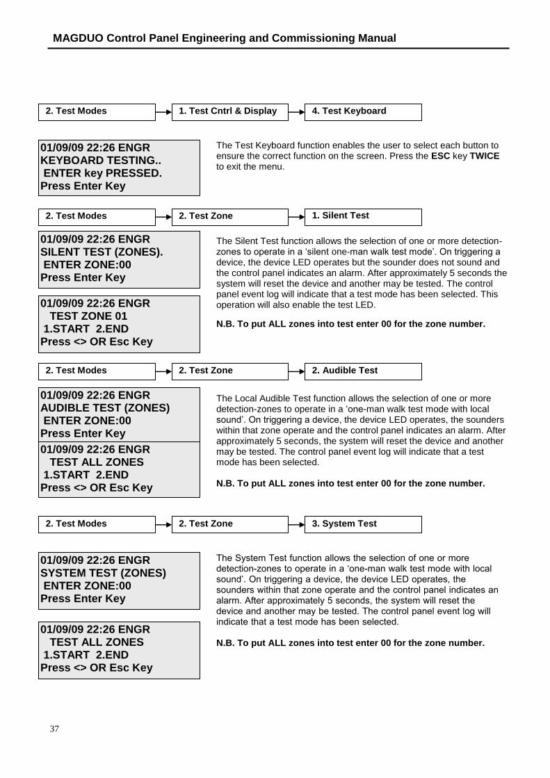
The Test Buzzer function toggles on and off to ensure correct buzzer operation unless the buzzer has been disabled by fitting a jumper link to LK1 on the PCB. The test light will illuminate while this action is taken.
The Test Keyboard function enables the user to select each button to ensure the correct function is shown on the screen. Press the ESC key TWICE to exit the menu.
The Silent Test function allows the selection of one or more detection-zones to operate in a ‘silent one-man walk test mode’. On triggering a device, the device LED operates, the sounder does not sound and the control panel indicates an alarm. After approximately 5 seconds the system will reset the device and another may be tested. The control panel event log will indicate that a test mode has been selected. This operation will also enable the test LED.
N.B. To put ALL zones into test, enter 00 for the zone number.
The Local Audible Test function allows the selection of one or more detection-zones to operate in a ‘one-man walk test mode with local sound’. On triggering a device, the device LED operates, the sounders within that zone operate and the control panel indicates an alarm. After approximately 5 seconds, the system will reset the device and another may be tested. The control panel event log will indicate that a test mode has been selected.
N.B. To put ALL zones into test enter 00 for the zone number.
2. Test Modes 1. Test Cntrls & Disp 4. Test Keyboard
2. Test Modes 2. Test Zone 1. Silent Test
2. Test Modes 2. Test Zone 2. Audible Test
01/09/09 22:26 SUPR BUZZER TESTING.. BUZZER ON Press Enter Key
01/09/09 22:26 SUPR KEYBOARD TESTING.. ENTER key PRESSED. Press Enter Key
01/09/09 22:26 SUPR SILENT TEST (ZONES). ENTER ZONE:00 Press Enter Key
01/09/09 22:26 SUPR TEST ZONE 01 1.START 2.END
Press <> OR Esc Key
01/09/09 22:26 SUPR AUDIBLE TEST (ZONES) ENTER ZONE:00 Press Enter Key
01/09/09 22:26 SUPR TEST ALL ZONES 1.START 2.END
Press <> OR Esc Key
2. Test Modes 1. Test Cntrls & Disp 3. Test Buzzer

MAGDUO Control Panel Engineering and Commissioning Manual
31
The System Test function allows the selection of one or more detection-zones to operate in a ‘one-man walk test mode with local sound’. On triggering a device, the device LED operates, the sounders within that zone operate and the control panel indicates an alarm. After approximately 5 seconds, the system will reset the device and another may be tested. The control panel event log will indicate that a test mode has been selected.
N.B. To put ALL zones into test enter 00 for the zone number.
This function allows the global disablement or enablement of all fire outputs on the panel. The control panel will indicate that disablements are present and a disablement event will be recorded to log.
This function allows the global disablement or enablement of all the sounders on the system. The control panel will indicate that disablements are present and a disablement event will be recorded to log.
This function allows output delays to be temporarily turned off.
This function allows the disablement or enablement of a detection zone. Thus, all the input devices (Manual Call Points, detectors and inputs) within that detection-zone will be disabled. The control panel will indicate that disablements are present and a disablement event will be recorded to log Automatic Detection devices will not activate, MCPs will activate but no event will be recorded to log and no programmed actions will occur. The sounder within the devices will still operate if triggered from elsewhere on the system.
2. Test Modes 2. Test Zone 3. System Test
3. Enable/ Disable 1. Remote Fire
3. Enable/ Disable 2. All Sounders
3. Enable/ Disable 4. Zone
01/09/09 22:26 SUPR SYSTEM TEST (ZONES) ENTER ZONE:00 Press Enter Key
01/09/09 22:26 SUPR TEST ALL ZONES 1.START 2.END
Press <> OR Esc Key
01/09/09 22:26 SUPR REMOTE FIRE:DISABLED 1.DISABLE 2.ENABLE
Press <> OR Esc Key
01/09/09 22:26 SUPR SOUNDERS:DISABLED 1.DISABLE 2.ENABLE
Press <> OR Esc Key
01/09/09 22:26 SUPR ZONE(ENABLE/DISABLE) ENTER ZONE:00 Press Enter Key
01/09/09 22:26 SUPR ZONE: ENABLED 1.DISABLE 2.ENABLE
Press <> OR Esc Key
3. Enable/ Disable 3. Delays
01/09/09 22:26 SUPR DELAYS: ENABLED 1.DISABLE 2.ENABLE
Press <> OR Esc Key

MAGDUO Control Panel Engineering and Commissioning Manual
26-1649-02
This allows the time and date to be adjusted. Use the UP and DOWN keys to move the cursor between options and the alphanumeric keypad to enter the code. Press the ENTER key to confirm the change. Note that this system will not keep time with BST/Daylight saving but will change date with leap years.
The Event Log stores 500 fire, fault and system events which may be displayed in entirety, or displayed by category. These are displayed in text format and may be scrolled through by pressing the UP and DOWN keys. Press the ESC key to exit the menu.
The Fire Log will display a log of any fire conditions received by the panel. These are displayed in text format and may be scrolled through by pressing the UP and DOWN keys. Press the ESC key to exit the menu.
The Fault Log will display a log of any fault conditions received by the panel. These are displayed in text format and may be scrolled through by pressing the UP and DOWN keys. Press the ESC key to exit the menu.
.
The Panel Event Log will display a log of events generated from the panel. These are displayed in text format and may be scrolled through by pressing the UP and DOWN keys. Press the ESC key to exit the menu.
3. Enable/ Disable 5. Peripheral Buss
4. Set Time and Date
5. View Logs 1. All Event Logs
5. View Logs 2. Fire Logs
5. View Logs 3. Fault Logs
5. View Logs 4. Panel Event Logs
01/09/09 22:26 SUPR DATE: 01/09/09 TIME: 22:36:00 Press Enter Key
EVT 069 OF 069 Z00: NA Engineer Mode 01/09/09 22:26:01
EVT 014 OF 014 Z01: Heat/Smoke 01/09/09 22:28:01
EVT 012 OF 012 Z01: EOL Missing 01/09/09 22:26:01
EVT 069 OF 069 Z00: NA Engineer Mode 01/09/09 22:26:01
This allows the Peripheral Buss to be switched on or off. Note: Ancillary equipment e.g. repeaters connected to the peripheral bus do not meet EN 54-2 requirements.
01/09/09 22:26 SUPR PERIPH BUSS: OFF
1. OFF 2. ONPress <> OR Esc Key

MAGDUO Control Panel Engineering and Commissioning Manual
33
Access Level 3 (Engineer): Controls Enabled LED flashing quickly
At Access Level 3A (Engineer), the main Fire Alarm Controls are enabled, and the following System Controls are accessible. To change options contained within the engineer menu, enter Access Level 3B. This is done by removing the right hand cover and moving the write enable switch to the ON position.
Note: A system reset must be done after any changes are made in order for them to take effect.

MAGDUO Control Panel Engineering and Commissioning Manual
26-1649-02
6. Zones 1. Zone Status
2. Zone Description
3. Zone Mode
7. Alarm Confirmation 1. Set Zone Type
2. Confirmation Type
3. Confirmation Delay
5. View Logs 1. All Event Logs
2. Fire Logs
3. Fault Logs
4. Panel Event Logs
8. Alarm Delay 1. Delay Zone o/ps
2. Delay Fire Relay
3. DLY monitored O/P1
4. DLY monitored O/P2
5. Delay Time
6. Zone of origin Delay
9. Panel Details 1. Buzzer
2. Access Code
1. ON / OFF
1. User
2. Supervisor
3. Engineer
3. Software Version
4. PNL identification 1. Panel Number
2. Panel Description
5. Timers 1. Weekly Test Timer
2. Service Timer
1. Weekly Test On/ Off
2. Weekly Test Day
3. Weekly Test Time

MAGDUO Control Panel Engineering and Commissioning Manual
35
Note: Ancillary equipment e.g. repeaters connected to the network do not meet EN 54-2 requirements.
These are described below. Note that actual display indications may differ from those shown in the grey boxes below, depending on actual set up.
The Active Log will display any current fires. These are displayed in text format and may be scrolled through by pressing the UP and DOWN keys. Press the ESC key to exit the menu.
10. Panel I/O 1. Programmable I/P 1
2. Programmable I/P 2
3. Monitored I/P
4. Monitored O/P 1
5. Monitored O/P 2
6. Fire Relay
7. Fault Relay
11. Peripheral Buss 1. PB RDU Supervise 1. RDU 1 Supervise
2. RDU 2 Supervise
3. RDU 3 Supervise
4. RDU 4 Supervise
5. RDU 5 Supervise
6. RDU 6 Supervise
7. RDU 7 Supervise
8. RDU 8 Supervise
1. View PB Baud Rate
2. View PB Mess Rate
2. PB Comm Configure
12. Printer 1. Printer Status
2. All Event Log
3. Fire Events
4. Fault Events
5. Panel Events
1. View Current Events 1. Current Fires
FIRE 001 OF 001 Z01: ZONE 01
Press <> OR Esc Key

MAGDUO Control Panel Engineering and Commissioning Manual
26-1649-02
.
The Active Log will display any current faults. These are displayed in text format and may be scrolled through by pressing the UP and DOWN keys. Press the ESC key to exit the menu.
The Active Log will display any current disables. These are displayed in text format and may be scrolled through by pressing the UP and DOWN keys. Press the ESC key to exit the menu.
The Active Log will display any current warnings. These are displayed in text format and may be scrolled through by pressing the UP and DOWN keys. Press the ESC key to exit the menu.
The Test Display function causes LCD screen to blacken and the test LED to illuminate.
The Test LEDs function causes the panel LEDs to toggle on/off to ensure correct operation. When this option is active, the test light will be illuminated.
The Test Buzzer function toggles on and off to ensure correct buzzer operation unless the buzzer has been disabled by fitting a jumper link to LK1 on the PCB. The test light will illuminate while this action is taken.
1. View Current Events 2. Current Faults
1. View Current Events 3. Current Disables
1. View Current Events 4. Current Warnings
2. Test Modes 1. Test Cntrl & Display 1. Test LCD display
2. Test Modes 1. Test Cntrl & Display 2. Test LEDs
2. Test Modes 1. Test Cntrl & Display 3. Test Buzzer
FAULT 001 OF 001 Z00: NA Batt – Low Vtg Press <> OR Esc Key
01/09/09 22:26 ENGR 01.REMOTE FIRE
Press <> OR Esc Key
01/09/09 22:26 ENGR
Press <> OR Esc Key
01/09/09 22:26 ENGR LEDs TESTING.. LEDs ON Press Enter Key
01/09/09 22:26 ENGR BUZZER TESTING.. BUZZER ON Press Enter Key
MAGDUO Control Panel Engineering and Commissioning Manual
37
The Test Keyboard function enables the user to select each button to ensure the correct function on the screen. Press the ESC key TWICE to exit the menu.
The Silent Test function allows the selection of one or more detection-zones to operate in a ‘silent one-man walk test mode’. On triggering a device, the device LED operates but the sounder does not sound and the control panel indicates an alarm. After approximately 5 seconds the system will reset the device and another may be tested. The control panel event log will indicate that a test mode has been selected. This operation will also enable the test LED.
N.B. To put ALL zones into test enter 00 for the zone number.
The Local Audible Test function allows the selection of one or more detection-zones to operate in a ‘one-man walk test mode with local sound’. On triggering a device, the device LED operates, the sounders within that zone operate and the control panel indicates an alarm. After approximately 5 seconds, the system will reset the device and another may be tested. The control panel event log will indicate that a test mode has been selected.
N.B. To put ALL zones into test enter 00 for the zone number.
The System Test function allows the selection of one or more detection-zones to operate in a ‘one-man walk test mode with local sound’. On triggering a device, the device LED operates, the sounders within that zone operate and the control panel indicates an alarm. After approximately 5 seconds, the system will reset the device and another may be tested. The control panel event log will indicate that a test mode has been selected.
N.B. To put ALL zones into test enter 00 for the zone number.
2. Test Modes 1. Test Cntrl & Display 4. Test Keyboard
2. Test Modes 2. Test Zone 1. Silent Test
2. Test Modes 2. Test Zone 2. Audible Test
2. Test Modes 2. Test Zone 3. System Test
01/09/09 22:26 ENGR KEYBOARD TESTING.. ENTER key PRESSED. Press Enter Key
01/09/09 22:26 ENGR SILENT TEST (ZONES). ENTER ZONE:00 Press Enter Key
01/09/09 22:26 ENGR TEST ZONE 01 1.START 2.END
Press <> OR Esc Key
01/09/09 22:26 ENGR AUDIBLE TEST (ZONES) ENTER ZONE:00 Press Enter Key
01/09/09 22:26 ENGR TEST ALL ZONES 1.START 2.END
Press <> OR Esc Key
01/09/09 22:26 ENGR SYSTEM TEST (ZONES) ENTER ZONE:00 Press Enter Key
01/09/09 22:26 ENGR TEST ALL ZONES 1.START 2.END
Press <> OR Esc Key

MAGDUO Control Panel Engineering and Commissioning Manual
01/09/09 22:26 ENGR FIRE RELAY: OFF
1.ON 2. OFFPress <> OR Esc Key
2. Test Modes 3. Activate Outputs 1. Fire Relay
Within this menu; selecting option 1. ON will turn on the fire relay and selecting option 2. OFF, will turn the fire relay off. If the fire relay is left in the ON or OFF condition and the activate outputs test is exited the relay will revert to normal operation.
Within this menu; selecting option 1. ON will turn on the fault relay and selecting option 2. OFF, will turn the fault relay off. If the fault relay is left in the ON or OFF condition and the activate outputs test is exited the relay will revert to normal operation.
2. Test Modes 3. Activate Outputs 2. Fault Relay
01/09/09 22:26 ENGR FAULT RELAY: ON
1.ON 2. OFFPress <> OR Esc Key
2. Test Modes 3. Activate Outputs 3. Monitored O/P 1
01/09/09 22:26 ENGR MONITORED OUTPUT 1: OFF
1.ON 2. OFFPress <> OR Esc Key
Within this menu; selecting option 1. ON will turn on monitored output 1 and selecting option 2. OFF, will turn monitored output 1 off. If the monitored output is left in the ON or OFF condition and the activate outputs test is exited then it will revert to normal operation.
2. Test Modes 3. Activate Outputs 4. Monitored O/P 2
01/09/09 22:26 ENGR MONITORED OUTPUT 2: OFF
1.ON 2. OFFPress <> OR Esc Key
Within this menu; selecting option 1. ON will turn on monitored output 2 and selecting option 2. OFF, will turn monitored output 2 off. If the monitored output is left in the ON or OFF condition and the activate outputs test is exited then it will revert to normal operation.
2. Test Modes 4. Test Inputs 1. Programmable I/P 1
01/09/09 22:26 ENGR PROG I/P 1 TESTING. INPUT ACTIVATED Press Enter Key
This will test programmable input 1 and when it is triggered INPUT ACTIVATED will be displayed on line 3 of the display.
2. Test Modes 4. Test Inputs 2. Programmable I/P 1
01/09/09 22:26 ENGR PROG I/P 2 TESTING. INPUT ACTIVATED Press Enter Key
This will test programmable input 2 and when it is triggered INPUT ACTIVATED will be displayed on line 3 of the display.
26-1649-02

MAGDUO Control Panel Engineering and Commissioning Manual
39
This function allows the global disablement or enablement of all fire outputs on the panel. The control panel will indicate that disablements are present and a disablement event will be recorded to log.
This function allows the global disablement or enablement of all the sounders on the system. The control panel will indicate that disablements are present and a disablement event will be recorded to log.
This function allows the sounders to either re-sound on another alarm or to remain in the silenced mode.
This function allows the disablement or enablement of a detection-zone. Thus, all the input devices (Manual Call Points, detectors and inputs) within that detection-zone will be disabled. The control panel will indicate that disablements are present and a disablement event will be recorded to log. Automatic Detection devices will not activate, MCPs will activate but no event will be recorded to log, and no programmed actions will occur. The sounder within the devices will still operate if triggered from elsewhere on the system.
3. Enable/ Disable 1. Remote Fires
3. Enable/ Disable 2. All Sounders
3. Enable/ Disable 4. Zone
01/09/09 22:26 ENGR REMOTE FIRE:DISABLED 1.DISABLE 2.ENABLE
Press <> OR Esc Key
01/09/09 22:26 ENGR SOUNDERS:DISABLED 1.DISABLE 2.ENABLE
Press <> OR Esc Key
01/09/09 22:26 ENGR ZONE(ENABLE/DISABLE) ENTER ZONE:00 Press Enter Key
01/09/09 22:26 ENGR ZONE: ENABLED 1.DISABLE 2.ENABLE
Press <> OR Esc Key
3. Enable/ Disable 3. Re-sound SoundersSounders
01/09/09 22:26 ENGR OPTION : AUTOMATIC 1.MANUAL 2.AUTO
Press <> OR Esc Key
2. Test Modes 4. Test inputs 3. Monitored I/P
01/09/09 22:26 ENGR MON I/P TESTING. INPUT ACTIVATED Press Enter Key
This will test monitored input and when it is triggered INPUT ACTIVATED will be displayed on line 3 of the display.

MAGDUO Control Panel Engineering and Commissioning Manual
26-1649-02
This allows the time and date to be adjusted. Use the UP and DOWN keys to move the cursor between options and the alphanumeric keypad to enter the code. Press the ENTER key to confirm the change. Note that this system will not keep time with BST/Daylight saving but will change date with leap years.
The Event Log stores 500 fire, fault and system events which may be displayed in entirety, or displayed by category. These are displayed in text format and may be scrolled through by pressing the UP and DOWN keys. Press the ESC key to exit the menu.
The Fire Log will display a log of any fire conditions received by the panel. These are displayed in text format and may be scrolled through by pressing the UP and DOWN keys. Press the ESC key to exit the menu.
The Fault Log will display a log of any fault conditions received by the panel. These are displayed in text format and may be scrolled through by pressing the UP and DOWN keys. Press the ESC key to exit the menu.
.
3. Enable/ Disable 5. Peripheral Buss
4. Set Time and Date
5. View Logs 1. All Event Logs
5. View Logs 2. Fire Logs
5. View Logs 3. Fault Logs
5. View Logs 4. Panel Event Logs
01/09/09 22:26 ENGR DATE: 01/09/09 TIME: 22:36:00 Press Enter Key
EVT 069 OF 069 Z00: NA Engineer Mode 01/09/09 22:26:01
EVT 014 OF 014 Z01: Heat/Smoke 01/09/09 22:28:01
EVT 012 OF 012 Z01: EOL Missing 01/09/09 22:26:01
01/09/09 22:26 SUPR PERIPH BUSS: OFF
2. OFF 2. ONPress <> OR Esc Key
This allows the Peripheral Buss to be switched on or off. Note: Ancillary equipment e.g. repeaters connected to the peripheral bus do not meet EN 54-2 requirements.

MAGDUO Control Panel Engineering and Commissioning Manual
41
. The Panel Event Log will display a log of events generated from the panel. These are displayed in text format and may be scrolled through by pressing the UP and DOWN keys. Press the ESC key to exit the menu.
The Zone Status will display the current zone status of any zone selected. These are displayed in text format and may be altered by pressing the LEFT and RIGHT keys. Once the correct setting is chosen press the ENTER key.
1. ON – Zone is active. 2. OFF – Zone is switched off.
The supply voltage to the selected zone will also be switched off.
The Zone description will display the zone description for the selected zone. These are displayed in text format and may be scrolled through by pressing the LEFT and RIGHT keys. To change the text, highlight the character to be changed and use the alphanumeric keypad to change that character. After changing a character, the cursor will automatically move to the next position. To confirm the changes press ENTER.
This active control will allow the engineer to choose the type of detectors that are to be used on the system. Use the LEFT and RIGHT keys to toggle through the following options. Once the correct option has been selected, press the ENTER key.
1. CP/DET – Original style MAGDUO FlexiPoint.
2. CP/SM/HT – New MAGDUO® ASD Device.
This active control will allow the engineer to change the selected zone type for ‘alarm confirmation’. Use the LEFT and RIGHT keys to toggle through the following options. Once the correct option has been selected, press the ENTER key.
6. Zones 1. Zone Status
6. Zones 2. Zone Description
6. Zones 3. Zone Mode
7. Alarm configuration 1. Set Zone Type
01/09/09 22:26 ENGR ZONE STATUS (ON/OFF) ENTER ZONE:00 Press Enter Key
01/09/09 22:26 ENGR ZONE STATUS: OFF 1.ON 2.OFF
Press <> OR Esc Key
01/09/09 22:26 ENGR ZONE NAMES ENTER ZONE:00 Press Enter Key
01/09/09 22:26 ENGR EDIT ZONE 01 NAME: ZONE 01 Press Enter Key
01/09/09 22:26 ENGR ZN TYPE: CP/DET 1.CP/DET 2.CP/SM/HTPress <> OR Esc Key
01/09/09 22:26 ENGR SET ZONE TYPE ENTER ZONE:00 Press Enter Key
EVT 069 OF 069 Z00: NA Engineer Mode 01/09/09 22:26:01

MAGDUO Control Panel Engineering and Commissioning Manual
26-1649-02
1. COMM. – Communal Zone – Smoke detectors onthis zone will immediately activate all soundersand outputs (subject to any other delaysprogrammed into the system).
2. DWELL – Dwelling Zone – Smoke detectors on
this zone will be subject to the ‘alarm confirmationdelay’ (for more information on this setting pleaserefer to the ‘alarm confirmation’ section).
This active control will allow the engineer to change the type of ‘alarm confirmation’ implemented. Use the LEFT and RIGHT keys to toggle through the following options. Once the correct option has been selected press the ENTER key.
1. SYSTEM – If any smoke detector on any other zone
enters an alarm condition whilst a detector isalready in ‘alarm confirmation’, the panel willoverride the delay and trigger a full alarm.
2. ZONAL – If any smoke detector on any other zoneenters an alarm condition whilst a detector isalready in ‘alarm confirmation’, then operation willbe as per the zone type for that zone. If the otherzone is set as an alarm confirmation dwell zonethen this will not trigger a full alarm, more than oneconfirmation can be running at a time in this mode.
This active control will allow the engineer to set the ‘alarm confirmation’ delay timer. Press 1 – 5 to set the timer from 1 Minute to 5 Minutes, then press ENTER to confirm the change.
This active control will allow the engineer to set an alarm delay for all sounders and outputs on the selected zone. Use the LEFT and RIGHT keys to toggle through the following options. Once the correct option has been selected, press the ENTER key.
1. INSTANT – When the panel receives a fire input,all sounders and outputs on the zone will immediately activate.
2. DELAYED – When the panel receives a fire input,all sounders and outputs on the
7. Alarm configuration 2. Confirmation Type
7. Alarm configuration 3. Confirmation Delay
8. Alarm Delay 1. Delay Zone O/Ps
01/09/09 22:26 ENGR ZONE: COMMUNAL 1.COMM. 2.DWELL.
Press <> OR Esc Key
01/09/09 22:26 ENGR OPTION : ZONAL 1.SYSTEM 2.ZONAL
Press <> OR Esc Key
01/09/09 22:26 ENGR CONFIRMATION DELAY DELAYS=1 (1-5 MIN) Press Enter Key
01/09/09 22:26 ENGR SET DELAY ZONE O/Ps ENTER ZONE:00 Press Enter Key
01/09/09 22:26 ENGR ZONE: INSTANT 1.INSTANT 2.DELAYED
Press <> OR Esc Key

MAGDUO Control Panel Engineering and Commissioning Manual
43
selected zone will be delayed for the time period set in the ‘Delay Timer’ menu.
This active control will allow the engineer to set an alarm delay for the panel fire relay. Use the LEFT and RIGHT keys to toggle through the following options. Once the correct option has been selected, press the ENTER key.
1. INSTANT – When the panel receives a fire input
the fire relay will immediately activate.
2. DELAYED – When the panel receives a fire inputthe fire relay will be delayed for the time period set in the ‘Delay Timer’ menu.
This active control will allow the engineer to set an alarm delay for Monitored Output 1. Use the LEFT and RIGHT keys to toggle through the following options. Once the correct option has been selected, press the ENTER key.
1. INSTANT – When the panel receives a fire input
Monitored Output 1 will immediately activate.
2. DELAYED – When the panel receives a fire inputMonitored Output 1 will be delayed for the time period set in the ‘Delay Timer’ menu.
This active control will allow the engineer to set an alarm delay for Monitored Output 2. Use the LEFT and RIGHT keys to toggle through the following options. Once the correct option has been selected, press the ENTER key.
1. INSTANT – When the panel receives a fire input
Monitored Output 2 will immediately activate.
2. DELAYED – When the panel receives a fire inputMonitored Output 2 will be delayed for
8. Alarm Delay 2. Delay Fire Relay
8. Alarm Delay 3. DLY monitored O/P11
8. Alarm Delay 4. DLY monitored O/P 2
01/09/09 22:26 ENGR FIRE RELAY: INSTANT 1.INSTANT 2.DELAYED
Press <> OR Esc Key
01/09/09 22:26 ENGR MON O/P 1 : INSTANT 1.INSTANT 2.DELAYED
Press <> OR Esc Key
01/09/09 22:26 ENGR MON O/P 2 : DELAYED 1.INSTANT 2.DELAYED
Press <> OR Esc Key

MAGDUO Control Panel Engineering and Commissioning Manual
26-1649-02
the time period set in the ‘Delay Timer’ menu.
This active control will allow the engineer to set the alarm delay timer. Press 0 – 5 to set the timer from No Delay to 5 Minutes, then press ENTER to confirm the change. If a delay time is set, then the Delay LED will be lit. Delayed zones or outputs will not be delayed if a zero time is selected.
This active control will allow the engineer to automatically override any delay in the zone of origin. Use the LEFT and RIGHT keys to toggle through the following options. Once the correct option has been selected press the ENTER key.
1. INSTANT – If any zone programmed with an
output delay enters an alarm condition, the output delay on that initiating zone will be cancelled. All other zones will operate as per their output delay settings.
2. SETTING – All zones will operate as per theiroutput delay settings.
This active control will allow the engineer to temporarily switch off the panel buzzer whilst in engineer mode. When the user exits engineer mode, the buzzer will be re-enabled. Use the LEFT and RIGHT keys to toggle through the options, then press ENTER to confirm the change.
This active control will allow the engineer to change the code for access to the user menus. Use the UP and DOWN keys to move the cursor between options and the alphanumeric keypad to enter the code. Press the ENTER key to confirm the change.
This active control will allow the engineer to change the code for access to the supervisor menus. Use the UP and DOWN keys to move
8. Alarm Delay 5. Delay Timer
8. Alarm Delay 6. Zone of Origin Delay
9. Panel Details 1. Buzzer 1. ON / OFF
9. Panel Details 2. Access Code 1. User
9. Panel Details 2. Access Code 2. Supervisor
01/09/09 22:26 ENGR ALARM DELAY DELAYS=0 (0-5 MIN) Press Enter Key
01/09/09 22:26 ENGR ORIGIN ZN : INSTANT 1.INSTANT 2.SETTING
Press <> OR Esc Key
EXISTING CODE:1111 NEW CODE : CONFIRM CODE : Press <> OR Esc Key
01/09/09 22:26 ENGR BUZZER: OFF 1.ON 2.OFF
Press <> OR Esc Key
EXISTING CODE:2222 NEW CODE : CONFIRM CODE : Press <> OR Esc Key

MAGDUO Control Panel Engineering and Commissioning Manual
45
the cursor between options and the alphanumeric keypad to enter the code. Press the ENTER key to confirm the change.
This active control will allow the engineer to change the code for access to the engineer menus. Use the UP and DOWN keys to move the cursor between options and the alphanumeric keypad to enter the code. Press the ENTER key to confirm the change.
This active control will allow the engineer to view the version of panel operating software implemented.
This active control will allow the engineer to view or change the panel ID Number. This is the number that identifies the panel on the network. Use the UP and DOWN keys to move the cursor between options and the alphanumeric keypad to enter the new ID Number. Please Note: Panel networking functions are not currently available.
This active control will allow the engineer to view or change the panel description. This is the name that identifies the panel on the network. Use the LEFT and RIGHT keys to move the cursor. To change the text, highlight the character to be changed and use the alphanumeric keypad to change that character. After changing a character, the cursor will automatically move to the next position. To confirm the changes press ENTER to accept the new description. Please Note: Panel networking functions are not currently available.
This active control will allow the engineer to enable or disable the weekly test timer. Use the LEFT AND RIGHT keys to toggle between the following options. To confirm the changes press ENTER.
9. Panel Details 2. Access Code 3. Engineer
9. Panel Details 3. Software Version
9. Panel Details 4. PNL identification 1. Panel Number
9. Panel Details 4. PNL identification 2. Panel Description
EXISTING CODE:3333 NEW CODE : CONFIRM CODE : Press <> OR Esc Key
01/09/09 20:13 ENGR SOFTWARE VERSION V1.04 Press Enter Key
01/09/09 20:13 ENGR OLD PANEL ID:01 NEW PANEL ID:00 Press <> OR Esc Key
01/09/09 20:13 ENGR EDIT PANEL NAME NAME: MAGDUO Press Enter Key
01/09/09 20:13 ENGR WEEKLY TEST: OFF 1.ON 2.OFF
Press <> OR Esc Key
9. Panel Details 5. Timers 1. Weekly Test Timer 1. Weekly Test On/Off

MAGDUO Control Panel Engineering and Commissioning Manual
26-1649-02
1. ON – Once a week at a determined day and time the routine service light will illuminate and the fault buzzer will sound to remind the user to perform their weekly test. The user will need to enter the user code or turn the key and reset the panel to clear.
2. OFF – Weekly test timer is switched off.
This active control will allow the engineer to view or change the day of the week on which the weekly test will be indicated. Use the UP and DOWN keys to toggle between the days of the week. To confirm the changes press ENTER.
This active control will allow the engineer to view or change the time of day at which the weekly test will be indicated. Use the alphanumeric keypad to enter a new time. To confirm the changes press ENTER.
This active control will allow the engineer to view or change the number of weeks between routine services. Use the alphanumeric keypad to enter a time interval up to 99 weeks. To confirm the changes press ENTER. When the routine service is indicated, the user must enter the engineer code and reset the panel to clear. Please Note: set week to 00 to switch timer off
This active control will allow the engineer to view or change the operation of programmable input 1. Use the UP and DOWN arrow keys to toggle through the following options. To confirm the changes press ENTER.
1. CONTROL EVENT – Operation of I/P 1 will operate a control function on the panel.
2. REMOTE FIRE EVENT– Operation of I/P 1 will signal a remote fire input at the control panel. Panel outputs will be triggered and fire indication will be shown at the control panel.
9. Panel Details 5. Timers 2. Service Timer
01/09/09 20:13 ENGR 1.MONDAY2.TUESDAYPress Enter Key
9. Panel Details 5. Timers 1. Weekly Test Timer 2. Weekly Test Day
01/09/09 20:13 ENGR WEEKLY TEST TIMER TIME= 10:00 (HH:MM) Press Enter Key
9. Panel Details 5. Timers 1. Weekly Test Timer 3. Weekly Test Time
01/09/09 20:13 ENGR WEEKLY TEST TIMER TIME= 10:00 (HH:MM) Press Enter Key
01/09/09 20:13 ENGR WEEKLY TEST TIMER TIME= 10:00 (HH:MM) Press Enter Key
01/09/09 20:13 ENGR SERVICE TIMER TIME= 06(0-99) WEEKS Press Enter Key
10. Panel I/O 1. Programmable I/P 1 1. Input Type
01/09/09 20:13 ENGR 1.CONTROL EVENT2.REMOTE FIRE EVENTPress Enter Key

MAGDUO Control Panel Engineering and Commissioning Manual
47
3. TECHNICAL EVENT – Operation of I/P 1 will signal a technical event at the control panel. Panel outputs will be triggered but the control panel will read technical alarm and no fire indication will be given.
4. DISABLEMENTS – Operation of I/P 1 will activate a disablement on the control panel.
5. DAY-NIGHT MODE – Operation of I/P 1 will activate the day mode on the control panel (MAGDUO FlexiPoint devices will be disabled; Devices will be disabled for smoke only but not for heat).
6. PROGRAM I/P 1 OFF – I/P 1 will not be active.
This active control will allow the engineer to view or change the operation of the control event set for programmable input 1. Use the UP and DOWN arrow keys to toggle through the following options. To confirm the changes press ENTER.
1. SILENCE ALARMS – Operation of I/P 1 will silence the alarms.
2. RESET SYSTEM – Operation of I/P 1 will reset the panel.
3. SOUND ALARMS – Operation of I/P 1 will send the evacuate signal to the panel.
4. SILENCE BUZZER – Operation of I/P 1 will silence the control panel buzzer.
This active control will allow the engineer to view or change the operation of the remote fire event set for programmable input 1. Use the UP and DOWN arrow keys to toggle through the following options. To confirm the changes press ENTER.
1. REMOTE FIRE FULL – Operation of I/P 1 will signal a remote fire at the control panel. All sounders and relays will operate.
2. REMOTE FIRE NO RELAYS – Operation of I/P 1 will signal a remote fire at the control panel and only the sounders will operate.
This active control will allow the engineer to view or change the operation of the technical event set for programmable input 1. Use the
10. Panel I/O 1. Programmable I/P 1 1. Input Type 1. Control Event
01/09/09 20:13 ENGR 1.SILENCE ALARMS2.RESET SYSTEMPress Enter Key
10. Panel I/O 1. Programmable I/P 1 1. Input Type 2. Remote Fire Event
01/09/09 20:13 ENGR 1.REMOTE FIRE- FULL2.REM FIRE,NO RELAYSPress Enter Key
10. Panel I/O 1. Programmable I/P 1 1. Input Type 3. Technical Event
01/09/09 20:13 ENGR TECHNICAL EVENT 1.LATCH 2.NON-LATCHPress Enter Key
MAGDUO Control Panel Engineering and Commissioning Manual
26-1649-02
UP and DOWN arrow keys to toggle through the following options. To confirm the changes press ENTER.
1. LATCH – Operation of I/P 1 will signal a technical event at the control panel. All outputs will trigger and the panel will latch into fire.
2. NON-LATCH – Operation of I/P 1 will signal a technical event at the control panel. All outputs will trigger for as long as the input is activated.

MAGDUO Control Panel Engineering and Commissioning Manual
49
This active control will allow the engineer to view or change the operation of the disablement event set for programmable input 1. Use the UP and DOWN arrow keys to toggle through the following options. To confirm the changes press ENTER.
1. DISABLE SOUNDERS – Operation of I/P 1 will disable the sounders.
2. DISABLE REM.FIRE – Operation of I/P 1 will disable all remote fire signals.
3. DIS SNDRS/REM FIRE – Operation of I/P 1 will disable all sounders and remote fire signals.
4. DISABLE BUZZER – Operation of I/P 1 will disable all remote fire signals.
This option allows the engineer to change the text that will be displayed on the panel when Programmable I/P 1 is activated. This is displayed in text format and may be scrolled through by pressing the LEFT and RIGHT keys. To change the text, highlight the character to be changed and use the alphanumeric keypad to change that character. After changing a character, the cursor will automatically move to the next position. To confirm the changes press ENTER.
10. Panel I/O 1. Programmable I/P 1 1. Input Type 4. Disablement
01/09/09 20:13 ENGR 1. DISABLE SOUNDERS2. DISABLE REM.FIREPress Enter Key
10. Panel I/O 1. Programmable I/P 1 2. Description
01/09/09 22:26 ENGR EDIT PROGRAMABLE IP1 NAME: PROG I/P 1 Press Enter Key

MAGDUO Control Panel Engineering and Commissioning Manual
26-1649-02
This active control will allow the engineer to view or change the operation of programmable input 2. Use the UP and DOWN arrow keys to toggle through the following options. To confirm the changes press ENTER.
1. CONTROL EVENT – Operation of I/P 2 will operate a control function on the panel.
2. REMOTE FIRE EVENT– Operation of I/P 2 will signal a remote fire input at the control panel. Panel outputs will be triggered and fire indication will be shown at the control panel.
3. TECHNICAL EVENT – Operation of I/P 2 will signal a technical event at the control panel. Panel outputs will be triggered but the control panel will read technical alarm and no fire indication will be given.
4. DISABLEMENTS – Operation of I/P 2 will activate a disablement on the control panel.
5. DAY-NIGHT MODE – Operation of I/P 2 will activate the day mode on the control panel (MAGDUO FlexiPoint devices will be disabled; devices will be disabled for smoke only but not for heat).
6. PROGRAM I/P 2 OFF – I/P 2 will not be active.
This active control will allow the engineer to view or change the operation of the control event set for programmable input 2. Use the UP and DOWN arrow keys to toggle through the following options. To confirm the changes press ENTER.
1. SILENCE ALARMS – Operation of I/P 2 will silence the alarms.
2. RESET SYSTEM – Operation of I/P 2 will reset the panel.
3. SOUND ALARMS – Operation of I/P 2 will send the evacuate signal to the panel.
4. SILENCE BUZZER – Operation of I/P 2 will silence the control panel buzzer.
10. Panel I/O 2. Programmable I/P 2 1. Input Type
01/09/09 20:13 ENGR 1.CONTROL EVENT2.REMOTE FIRE EVENTPress Enter Key
10. Panel I/O 2. Programmable I/P 2 1. Input Type 1. Control Event
01/09/09 20:13 ENGR 1.SILENCE ALARMS2.RESET SYSTEMPress Enter Key

MAGDUO Control Panel Engineering and Commissioning Manual
51
This active control will allow the engineer to view or change the operation of the remote fire event set for programmable input 2. Use the UP and DOWN arrow keys to toggle through the following options. To confirm the changes press ENTER.
1. REMOTE FIRE FULL – Operation of I/P 2 will signal a remote fire at the control panel. All sounders and relays will operate.
2. REMOTE FIRE NO RELAYS – Operation of I/P 2 will signal a remote fire at the control panel and only the sounders will operate.
This active control will allow the engineer to view or change the operation of the technical event set for programmable input 2. Use the UP and DOWN arrow keys to toggle through the following options. To confirm the changes press ENTER.
1. LATCH – Operation of I/P 2 will signal a technical event at the control panel. All outputs will trigger and the panel will latch into fire.
2. NON-LATCH – Operation of I/P 2 will signal a technical event at the control panel. All outputs will trigger for as long as the input is activated.
This active control will allow the engineer to view or change the operation of the disablement event set for programmable input 2. Use the UP and DOWN arrow keys to toggle through the following options. To confirm the changes press ENTER.
1. DISABLE SOUNDERS – Operation of I/P 2 will disable the sounders.
2. DISABLE REM.FIRE – Operation of I/P 2 will disable all remote fire signals.
3. DIS SNDRS/REM FIRE – Operation of I/P 2 will disable all sounders and remote fire signals.
4. DISABLE BUZZER – Operation of I/P 2 will disable all remote fire signals.
10. Panel I/O 2. Programmable I/P 2 1. Input Type 2. Remote Fire Event
01/09/09 20:13 ENGR 1.REMOTE FIRE- FULL2.REM FIRE,NO RELAYSPress Enter Key
10. Panel I/O 2. Programmable I/P 2 1. Input Type 3. Technical Event
01/09/09 20:13 ENGR TECHNICAL EVENT 1.LATCH 2.NON-LATCHPress Enter Key
10. Panel I/O 2. Programmable I/P 2 1. Input Type 4. Disablement
01/09/09 20:13 ENGR 1. DISABLE SOUNDERS2. DISABLE REM.FIREPress Enter Key
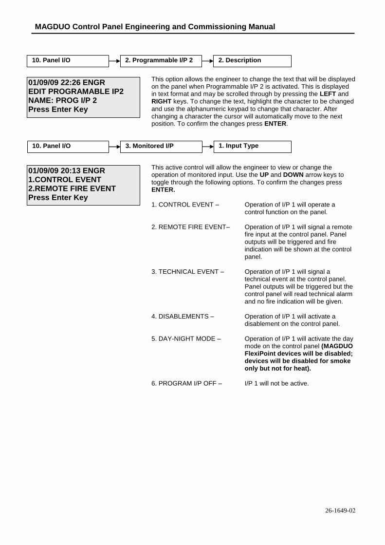
MAGDUO Control Panel Engineering and Commissioning Manual
26-1649-02
This option allows the engineer to change the text that will be displayed on the panel when Programmable I/P 2 is activated. This is displayed in text format and may be scrolled through by pressing the LEFT and RIGHT keys. To change the text, highlight the character to be changed and use the alphanumeric keypad to change that character. After changing a character the cursor will automatically move to the next position. To confirm the changes press ENTER.
This active control will allow the engineer to view or change the operation of monitored input. Use the UP and DOWN arrow keys to toggle through the following options. To confirm the changes press ENTER.
1. CONTROL EVENT – Operation of I/P 1 will operate a control function on the panel.
2. REMOTE FIRE EVENT– Operation of I/P 1 will signal a remote fire input at the control panel. Panel outputs will be triggered and fire indication will be shown at the control panel.
3. TECHNICAL EVENT – Operation of I/P 1 will signal a technical event at the control panel. Panel outputs will be triggered but the control panel will read technical alarm and no fire indication will be given.
4. DISABLEMENTS – Operation of I/P 1 will activate a disablement on the control panel.
5. DAY-NIGHT MODE – Operation of I/P 1 will activate the day mode on the control panel (MAGDUO FlexiPoint devices will be disabled; devices will be disabled for smoke only but not for heat).
6. PROGRAM I/P OFF – I/P 1 will not be active.
10. Panel I/O 3. Monitored I/P 1. Input Type
01/09/09 20:13 ENGR 1.CONTROL EVENT2.REMOTE FIRE EVENTPress Enter Key
10. Panel I/O 2. Programmable I/P 2 2. Description
01/09/09 22:26 ENGR EDIT PROGRAMABLE IP2 NAME: PROG I/P 2 Press Enter Key

MAGDUO Control Panel Engineering and Commissioning Manual
53
This active control will allow the engineer to view or change the operation of the control event set for monitored input. Use the UP and DOWN arrow keys to toggle through the following options. To confirm the changes press ENTER.
1. SILENCE ALARMS – Operation of I/P 1 will silence the alarms.
2. RESET SYSTEM – Operation of I/P 1 will reset the panel.
3. SOUND ALARMS – Operation of I/P 1 will send the evacuate signal to the panel.
4. SILENCE BUZZER – Operation of I/P 1 will silence the control panel buzzer.
This active control will allow the engineer to view or change the operation of the remote fire event set for monitored input. Use the UP and DOWN arrow keys to toggle through the following options. To confirm the changes press ENTER.
1. REMOTE FIRE FULL – Operation of I/P 1 will signal a remote fire at the control panel. All sounders and relays will operate.
2. REMOTE FIRE NO RELAYS – Operation of I/P 1 will signal a remote fire at the control panel and only the sounders will operate.
This active control will allow the engineer to view or change the operation of the technical event set for monitored input. Use the UP and DOWN arrow keys to toggle through the following options. To confirm the changes press ENTER.
1. LATCH – Operation of I/P 1 will signal a technical event at the control panel. All outputs will trigger and the panel will latch into fire.
2. NON-LATCH – Operation of I/P 1 will signal a technical event at the control panel. All outputs will trigger for as long as the input is activated.
10. Panel I/O 3. Monitored I/P 1. Input Type 1. Control Event
01/09/09 20:13 ENGR 1.SILENCE ALARMS2.RESET SYSTEMPress Enter Key
10. Panel I/O 3. Monitored I/P 1. Input Type 2. Remote Fire Event
01/09/09 20:13 ENGR 1.REMOTE FIRE- FULL2.REM FIRE,NO RELAYSPress Enter Key
10. Panel I/O 3. Monitored I/P 1. Input Type 3. Technical Event
01/09/09 20:13 ENGR TECHNICAL EVENT 1.LATCH 2.NON-LATCHPress Enter Key

MAGDUO Control Panel Engineering and Commissioning Manual
26-1649-02
This active control will allow the engineer to view or change the operation of the disablement event set for monitored input. Use the UP and DOWN arrow keys to toggle through the following options. To confirm the changes press ENTER.
1. DISABLE SOUNDERS – Operation of I/P will disable the sounders.
2. DISABLE REM.FIRE – Operation of I/P will disable all remote fire signals.
3. DIS SNDRS/REM FIRE – Operation of I/P 1 will disable all sounders and remote fire signals.
4. DISABLE BUZZER – Operation of I/P 1 will disable all remote fire signals.
This option allows the engineer to change the text that will be displayed on the panel when Monitored I/P is activated. This is displayed in text format and may be scrolled through by pressing the LEFT and RIGHT keys. To change the text, highlight the character to be changed and use the alphanumeric keypad to change that character. After changing a character the cursor will automatically move to the next position. To confirm the changes press ENTER.
This active control will allow the engineer to view or change the operation of Monitored O/P 1. Use the UP AND DOWN arrow keys to toggle through the following options. To confirm the changes press ENTER.
1. REMOTE SOUNDER – Operation of O/P 1 will mimic that of a conventional sounder circuit and will de-activate on SILENCE.
2. REMOTE FIRE – Operation of O/P 1 will mimic that of a remote fire circuit and will de-activate on RESET.
3. OFF – O/P 1 will not be active.
This option allows the engineer to change the text that will be displayed on the panel for Monitored O/P 1. This is displayed in text format and may be scrolled through by pressing the LEFT and RIGHT keys. To change the text, highlight the character to be changed and use the
10. Panel I/O 3. Monitored I/P1.
1. Input Type 4. Disablement
01/09/09 20:13 ENGR 1. DISABLE SOUNDERS2. DISABLE REM.FIREPress Enter Key
10. Panel I/O 3. Monitored I/P 2. Description
01/09/09 22:26 ENGR EDIT MONITORED I/P NAME: MON I/P Press Enter Key
10. Panel I/O 4. Monitored O/P 1 1. Output Type
01/09/09 20:13 ENGR 1.REMOTE SOUNDER2.REMOTE FIREPress Enter Key
10. Panel I/O 4. Monitored O/P 1 2. Description
01/09/09 22:26 ENGR EDIT MONITORED O/P1 NAME: MON O/P 1 Press Enter Key

MAGDUO Control Panel Engineering and Commissioning Manual
55
alphanumeric keypad to change that character. After changing a character the cursor will automatically move to the next position. To confirm the changes press ENTER.
This active control will allow the engineer to view or change the operation of Monitored O/P 2. Use the UP and DOWN arrow keys to toggle through the following options. To confirm the changes press ENTER.
1. REMOTE SOUNDER – Operation of O/P 2 will mimic that of a conventional sounder circuit and will de-activate on SILENCE.
2. REMOTE FIRE – Operation of O/P 2 will mimic that of a remote fire circuit and will de-activate on RESET.
3. OFF – O/P 2 will not be active.
This option allows the engineer to change the text that will be displayed on the panel for Monitored O/P 2. This is displayed in text format and may be scrolled through by pressing the LEFT and RIGHT keys. To change the text, highlight the character to be changed and use the alphanumeric keypad to change that character. After changing a character the cursor will automatically move to the next position. To confirm the changes press ENTER.
This option allows the engineer to change the text that will be displayed on the panel for relay 1. This is displayed in text format and may be scrolled through by pressing the LEFT and RIGHT keys. To change the text, highlight the character to be changed and use the alphanumeric keypad to change that character. After changing a character the cursor will automatically move to the next position. To confirm the changes press ENTER.
This option allows the engineer to change the text that will be displayed on the panel for relay 2. This is displayed in text format and may be scrolled through by pressing the LEFT and RIGHT keys. To change the text, highlight the character to be changed and use the alphanumeric keypad to change that character. After changing a character the cursor will automatically move to the next position. To confirm the changes press ENTER.
10. Panel I/O 7. Fault Relay
10. Panel I/O 6. Fire Relay
10. Panel I/O 5. Monitored O/P 2 1. Output Type
01/09/09 20:13 ENGR 1.REMOTE SOUNDER2.REMOTE FIREPress Enter Key
10. Panel I/O 5. Monitored O/P 2 2. Description
01/09/09 22:26 ENGR EDIT MONITORED O/P2 NAME: MON O/P 2 Press Enter Key
01/09/09 22:26 ENGR EDIT RELAY 1 NAME: FIRE Press Enter Key
01/09/09 22:26 ENGR EDIT RELAY 2 NAME: FAULT Press Enter Key

MAGDUO Control Panel Engineering and Commissioning Manual
26-1649-02
There are up to 8 peripheral devices addressed 1 to 8 that can be connected to a panel. When a peripheral device is enabled the panel will monitor it and report it as missing if there is a cable break or loss of communications.
The baud rate on the peripheral buss is fixed at 57,600 baud.
The Message rate is fixed at a 1 second update rate.
The printer functions are not currently in use.
11. Peripheral Buss
12. Printer
01/09/09 22:26 ENGR 1. PB RDU Supervise1. PB Comm ConfigurePress Enter Key
1. PB RDU Supervise 1. RDU 1 Supervise
RDU 1: Disabled
2. Disable 2. EnablePress <> or Esc Key
2. PB Comm Configure 1. View PB Baud Rate
2. PB Comm Configure 2. View PB Mess Rate
Note: Ancillary equipment e.g. repeaters connected to the peripheral bus do not meet EN 54-2 requirements.

MAGDUO Control Panel Engineering and Commissioning Manual
57
Alarm Delays
The following alarm outputs can be delayed for smoke detector alarms: Zone Outputs (zone sounders & IO outputs) Fire Relay Monitored output 1 Monitored output 2 Zone Of Origin
Manual Call Points always give instant operation, whichever type of zone they may be a part of.
Note: If the Zone Mode is set to CP/DET then a heat detector alarm will operate in the same way as a smoke detector alarm and use the ‘Delay’ time. In order for a heat detector alarm to override the ‘Delay’ time the zone mode must be set to CP/SM/HT.
The default delay time is 0, if this is set to anything other than zero the delay LED on the panel will illuminate even if all the above outputs are set to instant and the delay time is not being used.
The default setting for ‘Zone Of Origin’ is ‘Instant’. If an alarm occurs on a delayed zone the sounders on that zone will override the delay time and activate instantly.
To delay zone sounders on the zone of origin ‘Zone Of Origin’ must be set to ‘Settings’.
Configuring ‘Zone Of Origin’ to ‘Settings’ will apply to all zones on the system; sounders on all delayed zones will follow the delay time regardless of the origin of the fire.
Caution – Setting a delay of greater than 1 minute is outside the scope of EN54-2.

MAGDUO Control Panel Engineering and Commissioning Manual
26-1649-02
Alarm Confirmation
Introduction
The instructions in this section apply only to the Alarm Confirmation mode which is a part of the MAGDUO control panel and is supplementary to the rest of this manual.
The Alarm Confirmation technology has been designed primarily to address the problem of unwanted alarms in apartment blocks or ‘Houses of Multiple Occupancy’ (HMO).
The Alarm Confirmation facility enables certain detector alarms to be checked, or confirmed, before the entire system is activated. Furthermore, a local (at that detector) or zonal ‘Alarm Confirmation Warning’ sound is given, allowing any persons nearby to check the area for a possible fire. If the cause of the alarm is removed (e.g. burnt toast or a dust cloud) then the ‘Alarm Confirmation Warning’ will cease and the system returns to normal. If the cause of the alarm is still present at the end of the confirmation time then the entire system enters a full alarm state.
System planning prior to installation is essential, as certain zones need to be cabled separately, in order that they may be configured for ‘Dwelling’ (delayed) or ‘Communal’ (instant). e.g. The stairwell and communal corridors in a block of apartments will need to be wired on separate zones to the apartments.
If there is any doubt please refer to your supplier.
Zone Type
Each zone on the system can be separately configured as a Communal ‘Instant’ zone, or as a Dwelling (confirmation) zone. ‘Instant’ zones should be used for communal areas in apartment blocks and for escape routes such as stairwells, where normal fire alarm operation is required. Dwelling (confirmation) zones introduce an ‘Alarm Confirmation Delay’ to a smoke detector alarm on a zone, for use within apartments and other areas where unwanted alarms are likely to be a problem. Manual Call Points always give instant operation, whichever type of zone they may be a part of.
Note: If the Zone Mode is set to CP/DET then a heat detector alarm will operate in the same way as a smoke detector alarm and use the ‘Alarm Confirmation Delay’. In order for a heat detector alarm to override the ‘Alarm Confirmation Delay’ the zone mode must be set to CP/SM/HT.
Zones - Normal Operation in Communal Areas
Communal zones are those covering general access areas such as entrance hallways, corridors, stairwells etc., including any area which is an escape route for a private or dwelling area.
The activation of any Manual Call Point or detector in these areas generates an immediate alarm and operates the sounders in all areas.
The drawing below shows a typical arrangement with the communal areas shaded. This area should be cabled on its own zone and configured as a Communal Zone in the Zone Type setting menu.
CORRIDOR
FLAT FLAT FLAT FLAT FLAT
FLATFLATFLATFLATFLAT
CORRIDOR
FLAT FLAT FLAT FLAT FLAT
FLATFLATFLATFLATFLAT
Twinflex3 CPPlusPlans
BEDBEDBEDBED
LOUNGE KIT
HALL
CO
RR
IDO
R
KIT LOUNGE
HALL
BATH BATH

MAGDUO Control Panel Engineering and Commissioning Manual
59
Zones – ‘Confirmation Delay’ for Dwelling Areas
Dwelling zones are those covering apartments or private living areas. The activation of any smoke detector in these areas generates an ‘Alarm Confirmation Warning’ in that area but no indication shows on the control panel. The internal buzzer will sound at a very slow rate. At the end of every minute of the ‘Alarm Confirmation’ time the system will check the detector again to see if the activation has cleared. If so then the sounders will silence and no further action need be taken.
If, however, the detector is still activated at the end of the confirmation time, then the entire system will go into alarm, operating all the sounders and fire outputs on the system. The system can also be set such that any detector on another dwelling zone can confirm the alarm, see confirmation type below. The zones in confirmation can be viewed at access level 2 or 3 in the warnings menu option.
Note: If the Zone Mode is set to CP/DET then a heat detector alarm will operate in the same way as a smoke detector alarm and use the ‘Alarm Confirmation Delay’. In order for a heat detector alarm to override the ‘Alarm Confirmation Delay’ the zone mode must be set to CP/SM/HT.
Caution – Setting a delay of greater than 1 minute is outside the scope of EN54-2.
Local or Zonal Alarm Confirmation
Whilst a detector is in the ‘Confirmation State’ it may be configured to give an alarm confirmation warning at just that detector / sounder (Local Alarm Confirmation), or across that entire zone (Zonal Alarm Confirmation). This continues until the situation is confirmed, automatically cancelled or the panel is reset. If the device is still in fire after a reset, then a new confirmation time will start.
The drawing below shows a number of small Bed-Sit type apartments shaded; these are on one zone with just one FlexiPoint detector with sounder in each apartment. This area should be set as a ‘Dwelling Zone’.
The Alarm Confirmation should be set to operate the sounders in a local manner, so that in the event of an unwanted alarm, only the one apartment is alerted, this is done by setting DIL switch 2 to ON.
The activation of any Manual Call Point in a delayed (Dwelling) zone generates an immediate alarm and operates the sounders in all areas.
The Drawing below shows a larger apartment with several FlexiPoint detectors. The apartment should be cabled on its own zone and the Alarm Confirmation Alarm should be set to operate the sounders in a Zonal manner, so that all persons within the apartment are alerted, this is done by setting DIL switch 2 to OFF.
CORRIDOR
FLAT FLAT FLAT FLAT FLAT
FLATFLATFLATFLATFLAT
CORRIDOR
FLAT FLAT FLAT FLAT FLAT
FLATFLATFLATFLATFLAT
Twinflex3 CPPlusPlans
BEDBEDBEDBED
LOUNGE KIT
HALL
CO
RR
IDO
R
KIT LOUNGE
HALL
BATH BATH
CORRIDOR
FLAT FLAT FLAT FLAT FLAT
FLATFLATFLATFLATFLAT
CORRIDOR
FLAT FLAT FLAT FLAT FLAT
FLATFLATFLATFLATFLAT
Twinflex3 CPPlusPlans
BEDBEDBEDBED
LOUNGE KIT
HALL
CO
RR
IDO
R
KIT LOUNGE
HALL
BATH BATH

MAGDUO Control Panel Engineering and Commissioning Manual
26-1649-02
The detector DIL switch number 2 may be used to enable the ‘Logical Link’ which links the operation of the sounder to that individual detector whilst in confirmation warning stage. If this is set to the off position, the Alarm Confirmation Warning will sound in the entire zone.
DIL SWITCH SETTINGS
1 2 3 4 5 6 7 8
Logical Link * Logical link disabled (Zonal Confirmation) 0
Logical link enabled (Local Confirmation) 1
Confirmation Type
Confirmation Type can be set such that any detector on another dwelling zone can confirm the alarm or set so dwelling zones act independently.
With Confirmation Type set to ‘System’ if a second dwelling zone goes into alarm it will confirm the first dwelling zone alarm and cause the entire system to go into a full alarm, operating all the sounders and fire outputs on the system.
Setting the confirmation type to ‘Zonal’ means that multiple dwelling zones can be in alarm at the same time; they will work independently of each other and will not put the entire system into full alarm.
Caution – Setting the Confirmation Type to ‘Zonal’ is outside the scope of EN54-2.

MAGDUO Control Panel Engineering and Commissioning Manual
61
Installation and Commissioning
Installation 1st Stage
The installer must install the system wiring in the form of 2-core radial circuits. All cabling should be 2 core 1.5mm
2, screened and fire resistant, of an FP200 equivalent type. 4 core cable as a zone in and
zone out must not be used, due to the possibility of data corruption.
The zone should be left unconnected to the panel with no devices installed and must be tested for continuity and integrity with a multi-meter set to read Ohms.
The control panel back box should be mounted, with the mains supply tested, connected and isolated at the un-switched fused spur, ready for commissioning. Where the zone cabling is continued via the device, such as I/O modules, the cables should be temporarily connected through using connector blocks.
The installer needs to provide a set of ‘As-Wired’ drawings and proof of loop continuity and insulation test readings etc. before commissioning may proceed. This information is essential, and may be entered onto the forms provided at the rear of the manual.
Maximum Cable Lengths
Maximum cable lengths for Monitored Outputs and the Monitored Input is 10 metres. For Auxiliary Power, Programmable Inputs, Fire and Fault Output relays, the maximum length is 5 metres. The maximum cable length for a zone is 500m.
Installation 2nd Stage
Once the commissioning engineer is satisfied with the continuity / integrity of the zone cables, the control panel may be powered up as follows:
1. Ensure that none of the field wiring is connected to the panel. This is not essential butit helps to build up the system in sections when commissioning a system for the firsttime.
2. Apply the 230V AC mains supply, before connecting the batteries.
3. The control panel takes approximately half a minute to boot up its processor. Whenthis is complete, the empty zones and enabled I/O should all indicate a fault. This iscorrect.
4. Program the number of active zones required, and any other settings needed. This iseasier and quicker using a laptop PC and the MAGDUO software via the USB port.
5. Add a device to the end of each zone and ensure that the EOL signal is switched on inall these devices. Connect the zones into the control panel one at a time and ensurethat the fault lights clear as each zone is connected (after approx 20 sec).
6. Add the additional devices in one at a time. In the case of detectors, allow each one toclear from fault (approximately half a minute).
7. Connect all other circuits and ensure that they are fault free.
There is no requirement to build the system up in sections in this manner, but we recommend this method as good engineering practice to provide a controlled process of building up the system in blocks.

MAGDUO Control Panel Engineering and Commissioning Manual
26-1649-02
Commissioning
Commissioning the MAGDUO system involves programming and testing the system for correct operation.
It is essential that every device is tested in every mode of operation, and that all programmed actions are observed for correct operation. This includes the smoke testing of smoke detectors, heat testing of heat detectors, testing of Manual Call Points, testing of all inputs, testing of all sounders and outputs, and fault testing of detectors by head removal.
We also recommend that all devices, which are set to ‘heat only’, are tested for smoke operation, to ensure that the smoke detection has been correctly disabled.
Due to the complexity and inherent importance of a life protection type system, training on this equipment is essential, and commissioning should only be carried out by competent persons.
End User Training
A Fire Alarm System is of little use if the end user and/or the responsible persons who will be present in the building do not know how to operate and respond to the system. It is therefore essential that commissioning includes training for the users of the system and responsible persons.
User instructions and a Zone Chart should be left adjacent to the control panel. As access to the system must be controlled by responsible persons, it would be unusual to display the access codes on this notice. These codes must however be available for the responsible persons, so ensure that they know and record them in a secure place.
The MAGDUO User Guide should be explained and left with the responsible person on site, for storage in an accessible and known location, in order that the responsible person and the service engineer may keep information records up to date.
A single page user instruction sheet is included at the end of this manual. A copy of this should be mounted adjacent to the control panel.
Maintenance
The CIE does not require user maintenance other than checking the log at the service interval for any spurious faults or messages and checking that all programmed functions are still valid and operational and that all devices are working correctly.
The power supply batteries should be checked for leaks or low voltages during the regular service. The service interval is to be decided by the appropriate persons but should not be more than 12 monthly.

MAGDUO Control Panel Engineering and Commissioning Manual
63
Fault Finding
Summary of Faults
Intermittent Zone Fault
1. Tighten the unused ‘zone screw terminals’ at the EOL device and check all connectionson the zone.
2. Too many sounders on a zone. Remove some or adjust sound levels down.
3. EOL resistor, capacitor or third party EOL device has been fitted. Remove and use thecorrect DIL switch on the last device.
4. Interference from old or flickering fluorescent lights, low voltage transformers etc.Ensure that the cable is screened and install a ferrite core on the zone cables. Ensurethat the detector is away from light fittings and from light, especially direct or reflectedsunlight.
5. Dirty or contaminated optical chambers. Replace with a new optical chamber or device.
6. Weak EOL signal. Replace the EOL device.
7. Faulty auto-calibration of EOL signal. Replace the EOL device.
8. More than one EOL. Temporarily switch off the EOL at the last device to see if the faulthas cleared. If the system stays clear then another device is set to EOL and this mustbe found and switched off. It may be possible that more than 2 EOLs are switched on.
9. Earth fault. Ensure that all system earths are intact and not shorting to any other cablesor metal.
Permanent Zone Faults
1. More than one EOL switched ON. Temporarily switch off the EOL at the last device tosee if the fault has cleared. If the system stays clear then another device is set to EOLand this must be found and switched off.
2. No EOL signal detected by panel. Switch the EOL on at the last device.
3. O/C or S/C on zone cables. Remove the zone cable from the control panel and checkwith an electrical test meter (not a high voltage insulation test).
4. Tighten the unused ‘zone screw terminals’ at the EOL device.
5. Interference from old or flickering fluorescent lights, low voltage transformers etc.Ensure that the cable is screened and install a ferrite core on the zone cables. Ensurethat the detector is away from light fittings and from light, especially direct or reflectedsunlight.
6. Dirty or contaminated optical chambers. Replace with a new optical chamber or device.
7. Output unit with no power or no link in fault input. I/O module with no or incorrect inputresistor or input EOL switch incorrectly set (switch number 6).
8. Faulty Zone at control panel (22-30 volts healthy, 1-21 volts faulty, 1 volt or less, zoneswitched off or short circuit).
9. Weak EOL signal. Replace the EOL device.

MAGDUO Control Panel Engineering and Commissioning Manual
26-1649-02
False Alarms
1. Dirty or contaminated optical chambers. Replace with a new optical chamber or device.
2. Incorrectly set smoke detector (smoke is not suitable for kitchens, bathrooms, boilerrooms etc., however, SM3 may be suitable outside a bathroom or kitchen but theindividual situation needs to be looked at very carefully). Incorrectly set heat detector(HM1 is not suitable for kitchens, and HM3 should be kept for hotter areas such as plantrooms and commercial kitchens)
3. Faulty detector. Replace with a new one.
4. Ensure that the Optical Chamber is installed when the system is powered up, or a faultcondition will be generated. This could translate into a false alarm, depending on thestate of the detector.
General Faults
1. Sounder fault LED – this only activates for a fault on the conventional sounder circuit socheck for O/C, S/C and 10k EOL resistor.
2. Remote Fire Output fault LED – this only activates for a fault on the Remote Fire Outputso check for O/C, S/C and 10k EOL resistor. Check also that the relay used has thecorrect polarisation and suppression diodes installed.
3. Power fault - mains fault – Check that the 230V AC mains supply is live and the fusesare healthy.
4. Power fault, battery or charger fault – Check that the correct batteries are installed, thefuse has not blown and that the mains supply is live.
5. Earth fault. One of the circuits is connected to ground. Remove them one at a time untilthe relevant circuit is found, following which an electronic test meter may be used totrack the problem.

MAGDUO Control Panel Engineering and Commissioning Manual
65
Finding Zone Faults
A fault on a zone of the MAGDUO system may be found as follows:
1. In order to prove whether the fault is control panel based or in the field (including the fieldwiring), swap the wires from the zone in fault with those in a clear zone (active but no fault) atthe control panel.
If the fault moves with the wiring then the fault is in the field. If the fault stays on the same zone then the fault is in the control panel.
2. Examine the LEDs carefully for signs of the fault as follows:
If the buzzer has been silenced, create another fault to cause it to return, e.g. remove a battery lead until the buzzer starts again.
FlexiPoint LED action
Reason
20 second flash The detector is operating normally and is not set to EOL.
20 second dual flash The detector is operating normally, is set as heat only and is not set to EOL.
5 second flash The detector is operating normally and is set to EOL.
1.5 second flash The detector is in fault. Check for dust contamination and that the optical chamber is locked on correctly.
0.3 second flash or continuous The detector has triggered into the fire state and is not yet reset. Check for smoke and contamination.
Manual Call Point LED action
Reason
No LED The MCP is operating normally, or is not powered at all. Test the MCP to clarify.
5 second flash The MCP is operating normally and is set to EOL.
0.3 second flash The MCP has triggered into the fire state and is not yet reset.
3. If steps 1. and 2. do not clarify the matter then split the zone wiring at a suitable mid point,removing the outgoing cables from the terminals completely, and then setting the EOL switch tothe on position before reassembling that device.
If the fault clears then it is after that point, but if the fault persists then it is before that point.
The split may then be moved in the relevant direction, halving the remaining devices, and the procedure repeated until the fault is found.

MAGDUO Control Panel Engineering and Commissioning Manual
26-1649-02
Advanced Connections
Magnetic Door Hold Units
If magnetic door hold devices are required, it is recommended that they are connected as shown in the upper right diagram. This is suitable if it is convenient to cable to the control panel.
An Input/Output module may also be used for this operation, in which case a relay would not be required.
We recommend the use of 24V DC Magnetic Door Hold units, in order to enable them to operate from a power supply with a battery standby. This ensures normal operation in the event of an interruption to the power supply.
For assistance in choosing a suitable power supply unit, standby batteries, and Magnetic Door Hold units please contact your supplier.

MAGDUO Control Panel Engineering and Commissioning Manual
67
Connecting Two Panels Together
Only a maximum of two panels should be connected in this way.
For each panel, configure a monitored input as a remote fire event as follows: Monitored inputs on panels 1 and 2 should be set to remote fire event with no relay activation.
This active control will allow the engineer to view or change the operation of programmable input 1. Use the UP and DOWN arrow keys to toggle through the following options. To confirm the changes press ENTER.
2. REMOTE FIRE EVENT– Within this option select option 2. Rem Fire, No Relay. Operation of the Monitored I/P will signal a remote fire input at the control panel. Panel outputs will be triggered and fire indication will be shown at the control panel but the relays will not operate.
This will allow the fire condition to be reset from the panel that reported the fire. If the relays were set to operate then the fire condition would be re-triggered after a reset.
01/09/09 20:13 ENGR 1.CONTROL EVENT2.REMOTE FIRE EVENTPress Enter Key
10. Panel I/O 3. Monitored I/P MI 1 1. Input Type

MAGDUO Control Panel Engineering and Commissioning Manual
26-1649-02
Connecting four Panels Together
This active control will allow the engineer to view or change the operation of the programmable input. Use the UP and DOWN arrow keys to toggle through the following options. To confirm the changes press ENTER.
3. TECHNICAL EVENT – Operation of the Monitored I/P will signal a technical event at the control panel. Panel outputs will be triggered but the control panel will read technical alarm and no fire indication will be given.
This active control will allow the engineer to view or change the operation of a Monitored O/P. Use the UP and DOWN arrow keys to toggle through the following options. To confirm the changes press ENTER.
1. REMOTE SOUNDER – Operation of a Monitored O/P will mimic that of a conventional sounder
10. Panel I/O 4. Monitored O/P 1. Output Type
01/09/09 20:13 ENGR 1.REMOTE SOUNDER2.REMOTE FIREPress Enter Key
01/09/09 20:13 ENGR 1.CONTROL EVENT2.REMOTE FIRE EVENTPress Enter Key
10. Panel I/O 3. Monitored I/P MI 1. Input Type

MAGDUO Control Panel Engineering and Commissioning Manual
69
circuit and will de-activate on SILENCE.
MAGDUO Control Panel Engineering and Commissioning Manual
26-1649-02
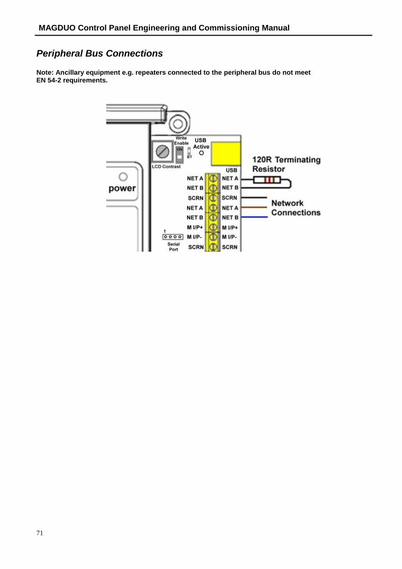
MAGDUO Control Panel Engineering and Commissioning Manual
71
Peripheral Bus Connections
Note: Ancillary equipment e.g. repeaters connected to the peripheral bus do not meet EN 54-2 requirements.
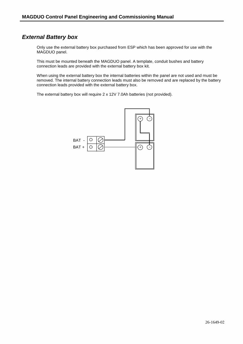
MAGDUO Control Panel Engineering and Commissioning Manual
26-1649-02
External Battery box
Only use the external battery box purchased from ESP which has been approved for use with the MAGDUO panel.
This must be mounted beneath the MAGDUO panel. A template, conduit bushes and battery connection leads are provided with the external battery box kit.
When using the external battery box the internal batteries within the panel are not used and must be removed. The internal battery connection leads must also be removed and are replaced by the battery connection leads provided with the external battery box.
The external battery box will require 2 x 12V 7.0Ah batteries (not provided).
+ -
+ - BAT +
BAT -

MAGDUO Control Panel Engineering and Commissioning Manual
73
Technical Data
Control Panel Specification 2 Zone Panel 4 Zone Panel 8 Zone Panel
Dimensions (mm) 331 x 331 x 99
Weight (excluding batteries)
2.25 kg 2.28 kg 2.36 kg
Construction V0 rated ABS
IP Rating IP 30
Cable Entry 13 x 20mm knockouts 1 x 50mm x 50mm pull out tab
Cable type 2 core 1.5mm2 screened fire rated cable, 500m (max per zone)
Detection zones 2 Max 4 Max 8 Max
Devices per zone Up to 32 Devices dependant on Device Loading Units (DLUs) not exceeding the stated maximum loading.
Device Protocol MAGDUO
Monitored sounder circuits Up to 2
Monitored relay circuits Up to 2
Relays on board Common fire and common fault
Operating standard BS EN54-2 & 4
Operating temperature 5OC to 40
OC
Control Panel Ratings
2/4/8 Zone Panel Mains voltage 230V AC Nominal 700mA
PSU output (4 hour continuous) 2.1A
Operating voltage Nominal 24V DC (Range 21-31V DC)
Battery charger output 300mA Max
Charger high impedance voltage <4V DC
Battery voltage (During Charge) 27.3 V DC @ 20OC
Internal Battery capacity 2 x 12V 3.2Ah (or 3.3 Ah) or 2 x 12V 3.2 Ah, Max load 1.8A
Maximum Internal resistance including connections and Fuse
1.3R
Zone output (max) 160 mA
MAGDUO zone voltage (nominal) 30V DC
Conventional zone voltage (nominal) 20V DC
Monitored Outputs 1 and 2 (max, fused)
300 mA trip polyfuse
Monitored Outputs 1 and 2 EOL 10k
Monitored Outputs 1 and 2 DC supply Current (max)
250 mA for a 2 – 4 zone panel 200mA for an 8 zone panel
Auxiliary DC supply Current (max) 250 mA
Auxiliary DC supply Volts, Unregulated
21V – 31V DC
Common fire relay Volt free SPCO contacts 1A 30V max
Common fault relay Volt free SPCO contacts 1A 30V max
Loading 160 DLUs max per zone
2 zone Imin (Required by EN54-4) 30mA @24V
4 zone Imin (Required by EN54-4) 40mA @ 24V
8 zone Imin (Required by EN54-4) 60mA @24V
Imax.a (Required by EN54-4) 350mA

MAGDUO Control Panel Engineering and Commissioning Manual
26-1649-02
Control Panel Fuses and Protection
2 Zone Panel 4/8 Zone Panel Zone output 300 mA trip polyfuse
Monitored Outputs 1 and 2 300 mA trip polyfuse
Auxiliary 24V DC supply 300 mA trip polyfuse
Mains T4A Time Delayed 20mm Ceramic (in mains terminal block)
Battery Charger 300mA current limiter
Battery (reverse polarity) 3.15A F 20mm (in line with battery leads) Glass
Note: Refer to the relevant sections in the manual for full details of input and output ratings

MAGDUO Control Panel Engineering and Commissioning Manual
75
Installation Checklist
Use the following checklist to ensure that your work is correct and that the commissioning engineer has the necessary information to complete the commissioning of the system
If you require a commissioning visit, the engineer will require this sheet, along with ‘Zone Continuity and Insulation Test Results’ and correctly marked ‘as-wired’ drawings, before attending site to commission the system.
Stage 1
Description Installation Engineer Checked
Commissioning Engineer Checked
Zone cables installed correctly, clipped or in containment.
All device bases and back boxes installed and terminated.
Cable insulation and continuity testing complete, and form filled out.
As-wired drawing marked up showing cable runs and devices.
Control panel back-box installed with 230V AC supply live, tested and isolated locally
Stage 2
Depending on the terms of your contract, you may also be required to carry out ‘Stage 2’.
Description Installation Engineer Checked
Commissioning Engineer Checked
Devices installed into bases and back-boxes
Detector dust covers fitted
Site Name & Address:
Installation Company:
Testing Engineer:
Signature:
Date:

MAGDUO Control Panel Engineering and Commissioning Manual
26-1649-02
Commissioning Checklist
The following checklist may be used to ensure that all steps are taken. This is not a BS5839 certificate and serves as a reminder only and may need additional items added to suit your working practices.
Step 1 Description Commissioning
Engineer Checked Panel powered up (230V AC Mains first, then batteries). Nothing else connected. All zones showing fault.
Program the number of ‘Active’ zones required, check that zones not required are clear of fault.
Low voltage multimeter test of cables to show no inter-core short circuits.
End of Line device installed with EOL switch in the ON position and remainder of devices added with DIL switches set, then each zone connected with approx 30 - 50 secs allowed to clear fault condition.
All faults (device, input, output, EOL, battery, etc,) cleared from control panel.
Step 2 Control panel programmed for any additional features.
All other cables connected and clear of fault.
Step 3 Correct operation of all input devices tested, ie. detectors, manual call points and inputs.
Correct operation of all output devices tested, ie. sounders, relays and outputs.
Correct operation of all programmed actions tested, ie. instant alarms, confirmation alarms, two stage alarms.
Step 4 System Manuals completed, zone chart or zone list displayed.
End user or responsible person trained and user manual issued.
Site Name & Address:
Commissioning Company:
Commissioning Engineer:
Signature:
Date:

MAGDUO Control Panel Engineering and Commissioning Manual
77
Cable Continuity & Insulation Test Results
After installation of the cable, and termination into all the relevant back-boxes, install a wire link between the zone +ve and –ve connections at the last device in order to be able to take cable continuity readings, removing it to take insulation readings. Make sure that all the cables are dressed smoothly and neatly into their back-boxes in order that they will not be disturbed after the readings are taken.
The commissioning engineer will require these readings, along with correctly marked ‘as-wired’ drawings, before attending site to commission the system.
Core Continuity Reading (ohms)
Z1 Z2 Z3 Z4 Z5 Z6 Z7 Z8
Zone +ve to –ve with a temporary link at the last device.
Others . .
A reading of approximately 1 ohm per 100 metres of 1.5 mm2 cable is expected and any significant
variation from this should be investigated. If the above readings are satisfactorily showing circuit continuity then you may also take the reading below, remembering to remove your temporary link at the last device.
Core Insulation Reading ( M ohms)
Z1 Z2 Z3 Z4 Z5 Z6 Z7 Z8
+ve to -ve
+ve to Earth
-ve to Earth
Screen to mains Earth: with scrn disconnected from panel
Others . .
A reading in excess of 1M ohm is expected and any significant variation from this should be investigated. If the readings are satisfactory then the zone wiring is largely proven other than for faults such as complete polarity reversal.
Site Name & Address:
Installation Company:
Testing Engineer:
Signature:
Date:

MAGDUO Control Panel Engineering and Commissioning Manual
26-1649-02
FIRE ALARM SYSTEM NOTICE
To Enable the Control Panel Keys
You may gain access to the fire alarm controls by inserting the key turning ¼ turn or by entering the USER code (default 1111). The ‘Controls Enabled’ LED should then be illuminated. If, after entering the code, further action is not taken, the ‘Controls Enabled’ light will eventually time out.
To disable the control panel keys, turn the key switch off. When disabled, the ‘Controls Enabled’ LED should then be extinguished. If a code was used, press ‘ESC’ to return to normal operation.
To prevent unauthorised operation, the controls should be kept disabled and the key/code kept secure under the control of the responsible person.
To Manually Operate the Fire Alarm Sounders
Enable the controls and then press ‘SOUND ALARMS’.
To silence the alarm sounders press ‘SILENCE ALARMS’.
Following a Fire Alarm Operation
The red ‘FIRE’ LED will illuminate. The fire alarms and the internal buzzer will operate as programmed. Take appropriate action as defined by the emergency plan for the premises.
To silence the alarm press ‘SILENCE ALARMS’, then establish the cause of the alarm and enter the details in the log book.
Reset any Manual Call Points which may have been operated, or if a detector has been operated be sure that the cause of the alarm has been removed, before resetting the system by pressing ‘RESET SYSTEM’.(Note when using certain conventional Detectors and MCP’s on the conventional expansion card a second reset of the system may be required).
Following a Fault Condition
The appropriate fault LEDs will illuminate. The internal buzzer will sound. To mute the internal buzzer press ‘SILENCE BUZZER’. Investigate and rectify the appropriate fault (competent persons). Once the fault has been rectified the fault indication will clear automatically.
Important Notes
FIRE ALARM COMPANY:
ADDRESS:
FOR SERVICE CALL: (Working hours) (Call Out)

MAGDUO Control Panel Engineering and Commissioning Manual
79
FIRE ALARM USER NOTICE
Note
The Fire alarm system installed in this building has ‘Alarm Confirmation’ technology to help eliminate false alarms.
Please read and understand the following information in order to make the most use of the system.
Operation
When the detector within your area activates it will initially only operate the sounders within your own area for a predetermined ‘Confirmation’ time.
At the end of the ‘Confirmation’ time the system will check the detector again to see if the activation has cleared. If so, the sounders will silence and no further action need be taken.
If, however, the detector is still activated, the entire system will go into alarm, operating all the sounders on the system.
Action Required
If you think that you may have accidentally set off the fire alarms, then check the following:
If the fire alarm within your area only is sounding, then check your own area for the cause of the alarm. If this proves to be a false alarm due to dust, cooking fumes, steam, cigarette smoke, etc, then clear the smoke from the area in order to allow the system to reset itself after a few minutes. If this happens then no further action is required. If the fire alarms in the communal areas are also sounding, then follow the building’s fire procedures for evacuation.
If you discover a genuine fire, then follow the building’s fire procedures for evacuation, activating the nearest Fire Alarm manual call point on the way out if the alarms are not already sounding.
Do not attempt to put out the fire unless it is safe to do so.
Further Information
Further information will be located adjacent to the Main Fire Alarm Control Panel, or may be obtained from either the person responsible for building maintenance or from the Fire Alarm Company responsible for maintaining the Fire Alarm System.
Confirmation Time before full alarm :- .......... Minutes
APARTMENT NOTICE FOR SYSTEMS USING ALARM CONFIRMATION

MAGDUO Control Panel Engineering and Commissioning Manual
26-1649-02
Engineers Notes

MAGDUO Control Panel Engineering and Commissioning Manual
81
Engineers Notes

MAGDUO Control Panel Engineering and Commissioning Manual
26-1649-02
Engineers Notes

MAGDUO Control Panel Engineering and Commissioning Manual
83
0832
Elite Security Products
Unit 7 Target Park, Shawbank Road,
Lakeside, Redditch, B98 8YN
England
11
DoP-MAGDUO2-01, DoP-MAGDUO4-01,
DoP-MAGDUO8-01
EN54-2: 1997 +A1: 2006, EN54-4: 1997
+A1: 2002 +A2: 2006
Intended for use in the fire detection and
fire alarm
Systems in and around buildings
Essential characteristics Performance Operational reliability Pass
Durability of operational
reliability and response delay,
Temperature resistance
Pass
Durability of operational
reliability, Vibration resistance Pass
Durability of operational
reliability, Humidity resistance Pass
Durability of operational
reliability, Corrosion resistance Pass
Durability of operational
reliability, Electrical stability Pass
Performance under fire
conditions Pass
Response delay (response time to
fire) Pass
Performance of power supply Pass
Technical Support
Due to the complexity and inherent importance of a life risk type system, training on this equipment is essential, and commissioning should only be carried out by competent persons.
ESP’s policy is one of continual improvement and the right to change a specification at any time without notice is reserved. Whilst every care has been taken to ensure that the contents of this document are correct at time of publication, ESP shall be under no liability whatsoever in respect of such contents. E&OE.

MAGDUO Control Panel Engineering and Commissioning Manual
26-1649-01