made in - architectural lighting · 8 alumleds™ | als210t.921.cali california a ccent lighting,...
TRANSCRIPT
Lighting for the Professional Designer
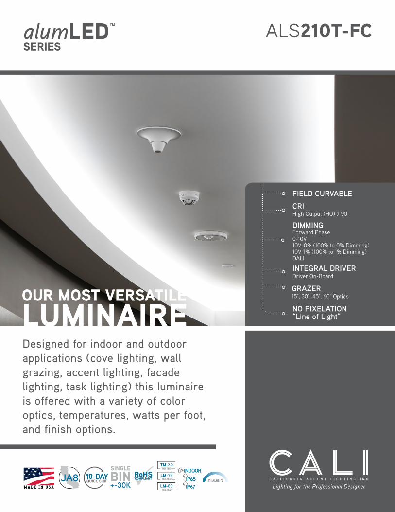
ALS210T-FC
Designed for indoor and outdoor applications (cove lighting, wall grazing, accent lighting, facade lighting, task lighting) this luminaire is offered with a variety of color optics, temperatures, watts per foot, and finish options.
SERIESalumLED™
ouR moST vERSaTILE
LumInaIRE NO PIXELATION“Line of Light”
GRAZER15°, 30°, 45°, 60° Optics
CRI High Output (HO) > 90
FIELD CURVABLE
INTEGRAL DRIVERDriver On-Board
DIMMING Forward Phase 0-10V10V-0% (100% to 0% Dimming)10V-1% (100% to 1% Dimming)DALI
M A D E I N
U S AM A D E I N USA
MA D E I N USA
10-DAY
TM-30TESTED
LM-79TESTED
LM-80TESTED
DIMMING

2 alumLEDs™ | ALS210T 2018
.01.1
2
800.921.CALI | CALIfornIA ACCent LIghtIng, InC.
aLS210T-FC PRoDuCT FEaTuRES
1.81”
2.04”
1.94”
Clear Lens120°
ALS210T-FCClear Lens
Asymmetric Lens
ALS210T-FCAsymmetric Lens
Optic Lens15°
Optic Lens30°
Optic Lens45°
Optic Lens60°
1.81”
2.04”
2.15”
1.81”
2.04”
2.15”
ALS210T-FCOptic Lens 15°, 30°, 45°, 60°
ALS210T-FCSemi-Frosted LensFrosted Lens
2.04”
2.15”
1.81” Semi-Frosted LensFrosted Lens
120 °
Field Curvable
17”Minimum Radius
12”
19.5”Minimum Radius
alumLEDs is a modular system that features individually replaceable integral drivers (where applied) and high-output LED modules, each one marked with an LED bin date code used as a reference for future replacements or maintenance on the system.
The integral heat sink and aluminum housing provide excellent thermal management, maintaining junction temperature to maximize LED life.
APPLICAtItOnS Indirect and Direct Lighting
PrImAry VOLAtGE 120V or 277V
SECOnDAry VDC 24VDC
LAmP tyPEHigh , mid, or Standard Output LEDs (no mercury)
LEnGtH Built to Order
COnStruCtIOn Aluminum Extrusion
mOuntInG mounting Clips
LIStInG
Dry or Wet (IP65 or IP67) LocationuL1598, CSA C22.2#250.0uL8750, CSA250uL2108, CSA C22.2 #9
CrIHigh Output (HO) > 90mid Output (mO) > 90Standard Output (SO) > 90
DImmInG
Forward Phase0-10V10V-0%10V-1%title 24DALI

alumLEDs™ | ALS210T 32018
.01.1
2
California aCCent lighting, inC. | calilighting.com
Color Vector Graphic
IES INDOOR REPORTPHOTOMETRIC FILENAME : L111602601.IES
POLAR GRAPH
87
174
261
348
1
2
Maximum Candela = 348.24 Located At Horizontal Angle = 0, Vertical Angle = 0# 1 - Vertical Plane Through Horizontal Angles (0 - 180) (Through Max. Cd.)# 2 - Horizontal Cone Through Vertical Angle (0) (Through Max. Cd.)
Photometric Toolbox Professional Edition - Copyright 2002-2012 by Lighting Analysts, Inc.Calculations based on published IES Methods and recommendations, values rounded for display purposes.Results derived from content of manufacturers photometric file.
Page 5
Maximum Candela = 348.24 Located At Horizontal Angle = 0, Vertical Angle = 0# 1 - Vertical Plane Through Horizontal Angles (0 - 180) (Through Max. Cd.)# 2 - Horizontal Cone Through Vertical Angle (0) (Through Max. Cd.)
Polar Graph 348
261
174
87
2
1
PERFoRmanCE
LAMP NUMBER DEscRiPtioNLUMENs PER WAtt
HiGH oUtPUt
MiD oUtPUt
stANDARD oUtPUt
LED-2.4K 2400K Incand. White 120 95 85
LED-2.7K 2700K Warm White 120 95 85
LED-3.0K 3000K Warm White 120 95 90
LED-3.5K 3500K neutral White 120 95 90
LED-4.0K 4000K neutral White 120 95 90
LED-4.5K 4500K neutral White 120 95 90
LED-5.0K 5000K Cool White 130 99 95
LED-5.7K 5700K Cool White 130 99 95430 440 460
470
480
490
500
510
520 530
540
550
560
570
580
590
600
610 620
630 640
650 700
380
0.4057, 0.3875
Y
X
0.9
0.8
0.7
0.6
0.5
0.4
0.3
0.2
0.1
0.1 0.2 0.3 0.4 0.5 0.6 0.7 0.8 0.90
0
Chromaticity Diagram
MEtRic REsULt NotEs
rf 90 IES tm-30-15 Fidelity Index
rg 101 IES tm-30-15 Gamut Index
CIE ra 95 CIE test Color method General Index
r9 72 CIE test Color method Sample nine Score
rf, skin 96 Average of CES15 and CES18 (skin)
CCt 3465 Correlated Color temperature
Duv -0.0015 Distance from the blackbody locus
x 0.4057 CIE 1931 chromaticity coordinate
y 0.3875 CIE 1931 chromaticity coordinate
u 0.2373 CIE 1960 chromaticity coordinate
v 0.3400 CIE 1960 chromaticity coordinate
u’ 0.2373 CIE 1976 chromaticity coordinate
v’ 0.5100 CIE 1976 chromaticity coordinate
tm-30
8165 E Kaiser Blvd. Anaheim, CA 92808www.lightlaboratory.com
Report No: L081710001TM30Date: 8/29/2017
*All Results in accordance to IES TM-30-15: IES Method for Evaluating Light Source Color Rendition
This plot shows a comparison of the Rf and Rg values relative to the range of possible values .
0%
20%
40%
60%
80%
100%
380 430 480 530 580 630 680 730 780
Rela
tive
Pow
er
Wavelength (nm)
SPECTRAL POWER DISTRIBUTION
Reference Illuminant
COLOR VECTOR GRAPHIC
COLOR DISTORTION GRAPHIC
1 2 1
2
Approx. limits for sources on the Planckian locus. Approx. limits for practical light sources.
60
70
80
90
100
110
120
130
140
50 60 70 80 90 100
Gam
ut In
dex,
Rg
Fidelity Index, Rf
Page 2 of 2

4 alumLEDs™ | ALS210T 2018
.01.1
2
800.921.CALI | CALIfornIA ACCent LIghtIng, InC.
CuSTom CoLoR FInIShES
Available in a variety of color options to fit your design. White BlackSatinNatural Silver
SilverGreen Red
CuSTom LEnSES
ALS210T-FC-SF(Semi-Frosted Lens50% Frosted)
ALS210T-FC(Clear Lens)
ALS210T-FC-F(Frosted Lens)(Standard OutputNo Pixelation)
ALS210T-FC Optics15D, 30D, 45D, 60D and AsymmetricAdd .282” to Optics Height
how To oRDER oR SPECIFy
EXAmPLE: ALS210t-CL-BK-LED-2.7K-3W-FP-SO-EF-Dry-120V-32”*1
Integral drivers wattage sized based on length of run. Example: 5’ run x 2 watts per foot = 10 watts. Driver will be sized to 10 watts maximum. Maximum length for line voltage (Integral Driver) Is 320 watts per run. Example: 320 watts ÷ 8 watts per foot = 40 feet max run.*2 Remote drivers sized based on wattage per length. Example: 10 feet x 8 watts = 80 watts. Drivers will be sized based on 80 watts. Consult factory for additional information. (Class II)*3
Clear Lens, Semi-Frosted Lens, and Frosted Lens (120°)
sERiEs oPtics FiNisH LAMP WAttsPER Foot DiMMiNG oUtPUt FEED PoiNt ListiNG LUMiNAiRE
voLtAGEFixtURE LENGtH
ALS210t Clear Lens(CL)*3
natural (nA) LED-2.4K 1.5 Watts (1.5W) 100% - 0&(10V-0%)
High Output(HO)
End Feed(EF)
Indoor(Dry)
120V Line Voltage(120V)*1
Specify LengthWhite (WH) LED-2.7K 2 Watts (2W)
Semi-Frosted Lens (SF)*3
Satin (SA) LED-3.0K 3 Watts (3W)100% - 1%(10V-1%)
mid Output(mO)
Bottom Feed(BF)
Outdoor IP65(WEt)
277V Line Voltage(277V)*1Black (BK) LED-3.5K 4 Watts (4W)
Frosted Lens:Line of Light
(F)*3
Green (Gn) LED-4.0K 5 Watts (5W) Standard Output(SO)
Side Feed(SF)
Outdoor IP67(WEt-IP67)
24V-120Vremote Driver
(24-120V)*2red (rD) LED-4.5K 6 Watts (6W) 0-10V (10V)
Silver (Sr) LED-5.0K 8 Watts (8W) Forward Phase (FP)(Only Available in120V Line Voltage)
Asymmetric Lens
(ASm)
LED-5.7K 12 Watts (12W) 24V-277Vremote Driver
(24-277V)*2
DALI (Only Available with remote Drivers)15° (15D)
30°D (30D)
45°D (45D) title 24 JA8(remote Driver)
(JA8-10V)60°D (60D)
Leave Blank fornon-Dimming

alumLEDs™ | ALS210T 52018
.01.1
2
California aCCent lighting, inC. | calilighting.com
aCCESSoRIES
Specify Length
Connect Two Fixtures with X” Custom Length Jumper Cables
6”
Connect Fixture Runs with 6” Jumper
Power Connectors Jumper Cables
Note: One mounting clip every 12” fixture.
Power Fixture with 6’ Cord
Power Fixture with 6’ Cord
Power Fixture with 6’ CordEnd Feed
Side Feed
Bottom Feed
Jumper Cable Options to Connect Two Luminaires
2”2” 2” 2”
ALS210t-FC-mC-1 ALS210t-FC-mC-2 ALS210t-FC-mC-3(Adjustable)
ALS210t-FC-mC-4-X(X=Specify Length)
(maximum Length 2’)
1.94”
2.03”
2.18”
1.94”
1.0”
2.94”
2.03”
1.94”
2.03”
X = Specify Length
1.89”
2.18”
3.13”
Adjustable Adjustable
mounting Clips

6 alumLEDs™ | ALS210T 2018
.01.1
2
800.921.CALI | CALIfornIA ACCent LIghtIng, InC.
DESIGn GuIDELInE
option a - Curved Runs
17”Minimum Radius
12”
19.5”Minimum Radius
Detail ADetail A
Detail A
Detail B
Detail B
#ALS210T-FC-MC-1(Center Screw)
Field Curvable
Power Connector#ALS210T-FC-PC
Power Connector#ALS210T-FC-PC
option B - Combination Runs
option B - Circular Runs
17”Minimum Radius
19.5”Minimum Radius
Detail ADetail A
Detail A
Detail A
Detail A
Detail A
Detail A
Detail B
Detail A
Detail B
Detail A
ALS210T-FC ALS210T-FC
ALS210T
ALS210T

alumLEDs™ | ALS210T 72018
.01.1
2
California aCCent lighting, inC. | calilighting.com
1.50” Min
2.50”Min
1.50”Min
2.50”Min
1.50”Min
ALS210T-FC-MC-2ALS210T-FC-MC-1
1.50”Min
2.50”Min
X= Specify Length
(Max Length 4’)
3.00”Min
3.40”Min
ALS210T-FC-MC-4-XX = Specify Length
ALS210T-FC-MC-3(Adjustable)
mounTInG CovE DESIGn GuIDELInES

8 alumLEDs™ | ALS210T 2018
.01.1
2
800.921.CALI | CALIfornIA ACCent LIghtIng, InC.
CaLIFoRnIa aCCEnT LIGhTInG, InC.2034 E. Lincoln Ave. #431, Anaheim, CA 92806ph. 800.921.CALI or 714.535-7900 | fx. [email protected] | calilighting.com© CALI. All rights reserved. CALI reserves the right to make changes or withdraw specifications without prior notice. MA D E I N USA 20
18.0
1.12