macro-tech® - ae techron · some models may be exported under the name amcron ... 4.3.3 error amp...
TRANSCRIPT

POWER AMPLIFIER
SERVICE MANUAL
130445-102-00Rev. A
Macro-Tech®
©2000 by Crown International, Inc., P.O. Box 1000, Elkhart, Indiana 46515-1000 U.S.A.Telephone: 219-294-8000. Trademark Notice: PIP™, Grounded Bridge™ and SmartAmp™ aretrademarks and Amcron®, Crown®, Macro-Tech®, IOC®, ODEP®, and IQ System® are registeredtrademarks of Crown International, Inc. Other trademarks are the property of their respectiveowners.
Models:MA-2402
Some models may be exported under the name Amcron®
MA-2402 Service Manual
II
130445-1 Rev. A
©2000 Crown International, Inc.
À PRÉVENIR LE CHOCÉLECTRIQUE N’ENLEVEZPAS LES COUVERTURES.
RIEN DES PARTIESUTILES À L’INTÉRIEUR.
DÉBRANCHER LA BORNEAVANT D’OUVRIR LA
MODULE EN ARRIÈRE.
TO PREVENT ELECTRIC SHOCK DONOT REMOVE TOP OR BOTTOM
COVERS. NO USER SERVICEABLEPARTS INSIDE. REFER SERVICING
TO QUALIFIED SERVICEPERSONNEL. DISCONNECT
POWER CORD BEFORE REMOVINGREAR INPUT MODULE TO ACCESS
GAIN SWITCH.
CAUTION AVIS
WARNINGTO REDUCE THE RISK OF ELECTRIC
SHOCK, DO NOT EXPOSE THISEQUIPMENT TO RAIN OR MOISTURE!
The information furnished in this manual does not include all of the details of design, production, or variationsof the equipment. Nor does it cover every possible situation which may arise during installation, operation ormaintenance. If you need special assistance beyond the scope of this manual, please contact the CrownTechnical Support Group.
Mail: P.O. Box 1000 Elkhart IN 46515-1000Shipping: Plant 2 SW 1718 W. Mishawaka Road Elkhart IN 46517
Phone: (800) 342-6939 / (219) 294-8200FAX: (219) 294-8301
The lightning bolttriangle is used toalert the user to therisk of electric shock.
The exclamation pointtriangle is used to alert theuser to important operatingor maintenance instructions.

III
130445-1 Rev. A MA-2402 Service Manual
©2000 Crown International, Inc.
Revision History
Revision Number Date Comments
Rev. A 02-2000 Initial Printing

MA-2402 Service Manual
IV
130445-1 Rev. A
©2000 Crown International, Inc.
This page intentionally left blank

V
130445-1 Rev. A MA-2402 Service Manual
©2000 Crown International, Inc.
Table of Contents1 Introduction ............................................................................ 1-1
1.1 Introduction ................................................................................ 1-11.2 The MA “02” Series Amplifiers ................................................... 1-11.3 Scope ......................................................................................... 1-11.4 Warranty ..................................................................................... 1-1
2 Specifications ......................................................................... 2-1
3 Voltage Conversion ................................................................ 3-1
4 Circuit Theory ........................................................................ 4-14.1 Overview .................................................................................... 4-14.2 Features ..................................................................................... 4-14.3 Front End Operation ................................................................... 4-1
4.3.1 Balanced Gain Stage (BGS) ............................................. 4-14.3.2 Variable Gain Stage (VGS) ................................................ 4-14.3.3 Error Amp .......................................................................... 4-1
4.4 Voltage Amplification ................................................................. 4-24.4.1 Voltage Translators ........................................................... 4-24.4.2 Last Voltage Amplifiers (LVAs) .......................................... 4-2
4.5 Grounded Bridge Topology ....................................................... 4-24.5.1 High Side (HS) .................................................................. 4-24.5.2 Low Side (LS) .................................................................... 4-3
4.6 Output Device Emulation Protection (ODEP) ............................. 4-4
5 Maintenance........................................................................... 5-15.1 Cautions and Warnings .............................................................. 5-15.2 General Information ................................................................... 5-15.3 Test Procedures ........................................................................ 5-1
5.3.1 Turn On Delay .................................................................. 5-15.3.2 Output Bias Adjustment ................................................... 5-15.3.3 ODEP Voltage Adjustment ............................................... 5-15.3.4 DC Offset ........................................................................... 5-25.3.5 Quiescent Power Draw..................................................... 5-25.3.6 Voltage Gain ..................................................................... 5-25.3.7 Current Limit ..................................................................... 5-25.3.8 10 kHz Square Wave Response ...................................... 5-35.3.9 Crosstalk .......................................................................... 5-35.3.10 Output Power ................................................................. 5-35.3.11 ODEP Limiting ................................................................ 5-35.3.12 Fan Operation ................................................................ 5-45.3.13 LF Protection .................................................................. 5-45.3.14 Signal to Noise ............................................................... 5-4

MA-2402 Service Manual
VI
130445-1 Rev. A
©2000 Crown International, Inc.
5.3.15 Intermodulation Distortion (IMD) .................................... 5-45.3.16 Displays.......................................................................... 5-45.3.17 Post Testing.................................................................... 5-4
6 Parts ....................................................................................... 6-16.1 General Information .................................................................. 6-16.2 Ordering and Receiving Parts .................................................. 6-16.2.1 Terms ..................................................................................... 6-16.2.2 Shipment ................................................................................ 6-1
7 Exploded View Parts ............................................................. 7 -1
8 Module and Schematic Information ..................................... 8 -1
9 Module Parts .......................................................................... 9-1
10 Schematics ........................................................................ 10-1
Table of Contents

Introduction 1-1
130445-1 Rev. A MA-2402 Service Manual
©2000 Crown International, Inc.
1.1 IntroductionThis manual contains complete service informationon the Crown® MA-2402 power amplifier. It is designedto be used in conjunction with the Reference Manual;however, some important information is duplicated inthis Service Manual in case the Reference Manual isnot readily available.
NOTE: THE INFORMATION IN THIS MANUAL ISINTENDED FOR USE BY AN EXPERIENCED TECH-NICIAN ONLY!
1.2 The MA “02” Series AmplifiersThe Macro-Tech® series is a complete family of am-plifiers designed for pro sound reinforcement. Macro-Tech amplifiers are designed to provide enormouslevels of pure, undistorted power in a rugged low-pro-file package, utilizing Crown's patented GroundedBridge™ output topology. They also employ Crown'spatented ODEP® protection circuitry, which keeps theamplifier working under extreme conditions that wouldshut down a lesser amplifier. Crown's new Macro-Tech“02” series amplifiers feature Crown's enhancedPIP2™ (Programmable Input Processor) expansionsystem. The PIP2 expansion system makes it easy totailor the amplifier to a specific application. Providinghigh power amplification from 20 Hz to 20 kHz withminimum distortion, Macro-Tech series amplifiers fea-
ture balanced inputs with bridged and parallel mono-phonic capability. Specific features vary dependingon model.
1.3 ScopeThis Service Manual in intended to apply to all ver-sions of the MA-2402 amplifier. The Parts Listings in-clude parts specific for the US version and the Euro-pean version (E13CE). For parts specific only to otherversions contact the Crown Technical Support Groupfor help in finding part numbers.
1.4 WarrantyEach Reference Manual contains basic policies asrelated to the customer. In addition, it should be statedthat this service documentation is meant to be usedonly by properly trained personnel. Because mostCrown products carry a 3-Year Full Warranty (includ-ing round trip shipping within the United States), allwarranty service should be referred to the Crown Fac-tory or Authorized Warranty Service Center. See theapplicable Reference Manual for warranty details. Tofind the location of the nearest Authorized WarrantyService Center or to obtain instructions for receivingCrown Factory Service, please contact the CrownTechnical Support Group (within North America), oryour Crown/Amcron Importer (outside North America).If you are an Authorized Warranty Service Center andhave questions regarding the warranty of a product,please contact the Field Service Manager or the Tech-nical Support Group.
Crown Customer ServiceTechnical Support Group
Factory ServiceParts Department
Mailing Address: P.O. Box 1000, Elkhart IN 46515Shipping Address: Plant 2 S. W.
1718 W. Mishawaka Rd., Elkhart IN 46517Phone: (219) 294-8200
Toll Free: (800) 342-6939Fax: (219) 294-8301
http://www.crownaudio.com
1 Introduction
MA-2402 Service Manual
1-2 Introduction
130445-1 Rev. A
©2000 Crown International, Inc.
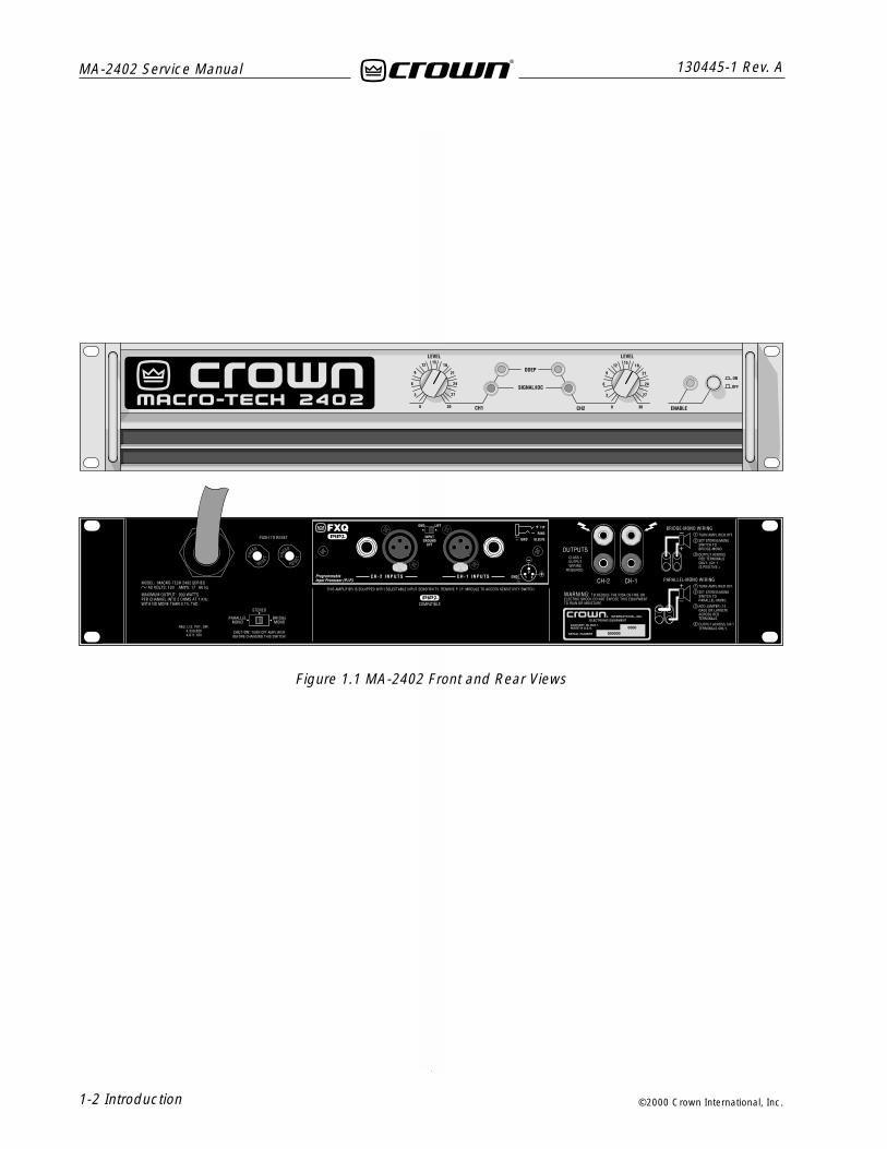
Figure 1.1 MA-2402 Front and Rear Views

Specifications 2-1
130445-1 Rev. A MA-2402 Service Manual
©2000 Crown International, Inc.
6 SpecificationsNote: Specifications relate to 120-volt,60-Hz units in Stereo mode with 8-ohm loads andan input sensitivity of 26-dB gain at 1-kHz rated power unless otherwise specified.Specifications for units supplied outside the U.S.A. may vary slightly at different ACvoltages and frequencies.
Power
Output Power:
Load Impedance: Safe with all types of loads. Rated for 2 to 16ohms in Stereo, 4 to 16 ohms in Bridge-Mono and 1 to 4 ohms inParallel-Mono mode.
Voltage Gain to 1-kHz, 8-ohm rated output;
83:1 ±12% or 38 dB ±0.5 dB at 0.775-volt sensitivity;
46:1 ±12% or 33 dB ±0.5 dB at 1.4-volt sensitivity.
20:1 ±3% or 26 dB ±0.25 dB at 3.1-volt sensitivity at the maximumlevel setting.
Required AC Mains: 50/60 Hz; 100-, 120-, 220- and 240-VAC(±10%) units are available. All draw 100 watts or less at idle.Current, voltage and frequency requirements are provided on theunit’s back-panel.
AC Line Connector: NEMA 5-20P (20A).
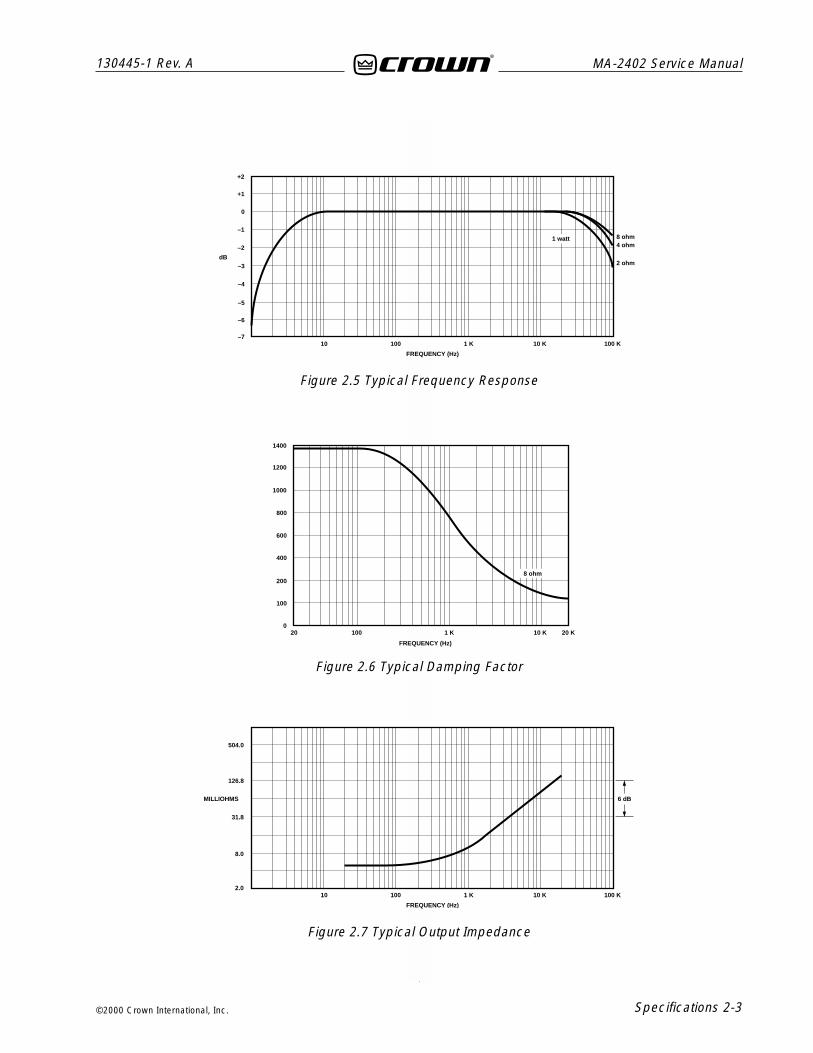
PerformanceFrequency Response: ±0.1 dB from 20 Hz to 20 kHz at 1 watt (seeFigure 2.5).
Phase Response: ±10 degrees from 10 Hz to 20 kHz at 1 watt (seeFigure 2.3)..
Signal-to-Noise Ratio, A-weighted:
Better than 105 dB below rated full bandwidth power.
20 Hz to 20 kHz:
Better than 100 dB below full bandwidth power.
Total Harmonic Distortion (THD): full bandwidth power, Less than0.05% from 20 Hz to 1 kHz increasing linearly to 0.1% at 20 kHz.
Intermodulation Distortion (IMD): (60 Hz and 7 kHz at 4:1) Lessthan 0.05% from 163 milliwatts to full bandwidth power.
Damping Factor: Greater than 1,000 from 10 Hz to 400 Hz (seeFigure 2.6).
Crosstalk: See Figure 2.4.
Slew Rate: (Slew rates are limited to useful levels for ultrasonic/RFprotection). Greater than 13 volts per microsecond.
ControlsEnable: A front-panel push button used to turn the amplifier on andoff.
Level: A front-panel 31-detent rotary control for each channel usedto control the output level.
Stereo/Mono: A three-position back-panel switch used to selectStereo, Bridge-Mono or Parallel-Mono mode.
Sensitivity: A three-position switch inside the PIP compartmentused to select the input sensitivity for both channels: 0.775 volts or1.4 volts for standard 1-kHz power, or a 26 dB voltage gain.
Reset: A back-panel push button for each channel used to reset thecircuit breaker that protects each power supply.
IndicatorsEnable: An amber front-panel indicator that shows the on/off statusof the low-voltage power supply.
Signal/IOC: A green front-panel indicator for each channel thatflashes to show amplifier output. If a channel’s output waveformdiffers from its input by 0.05% or more, the indicator flashesbrightly to show distortion. This function provides proof ofdistortion-free performance. In Parallel-Mono mode, the Channel 2light stays on.
ODEP: An amber front-panel indicator for each channel that showsthermal-dynamic energy reserve. Normally, each ODEP indicator islit to show available reserve energy. In the rare event that a channelhas no reserve, its indicator will dim in proportion to ODEP limiting.An ODEP indicator may also turn off under other conditions.
Input/OutputInput Connector: Two balanced ¼-inch(6.35-mm) phone jacks andtwo balanced three-pin female XLR connectors on the factory-installed PIP2-FXQ.
Input Impedance: Nominally 20 k ohms, balanced. Nominally 10 kohms, unbalanced.
Maximum Input Level: 9 Vrms.
Input Sensitivity: 0.775 volts for standard 1 kHz power, 1.4 voltsfor standard 1 kHz power, or a 26 dB voltage gain.
Output Connectors: Two sets of color-coded 5-way binding posts(for banana plugs, spade lugs or bare wire).
Output Impedance: Less than 10 milliohms in series with less than2 microhenries (see Figure 2.7).
DC Output Offset: (Shorted input) ±10 millivolts.
Output SignalStereo: Unbalanced, two-channel.
Bridge-Mono: Balanced, single-channel. Channel 1 controls areactive; Channel 2 should not be used.
Parallel-Mono: Unbalanced, single-channel. Channel 1 controls areactive; Channel 2 controls are bypassed.
ProtectionMacro-Tech amplifiers are protected against shorted, open ormismatched loads; overloaded power supplies; excessive tempera-ture; chain destruction phenomena; input overload damage; andhigh-frequency blowups. They also protect loudspeakers frominput/output DC and turn-on/turn-off transients.
If unreasonable operating conditions occur, the patented ODEPcircuitry will proportionally limit the drive level to protect the output
2-ohm Dual (per ch.)
1 kHzPower
1,050W
800W520W
2,070W
1,585W
850W
750W505W
1,670W
1,485W8-ohm Bridge-Mono
4-ohm Bridge-Mono
8-ohm Dual (per ch.)
4-ohm Dual (per ch.)
*1 kHz Power: refers to maximum average power in watts at 1 kHz with 0.1% THD.**20 Hz– 20 kHz Power: refers to maximum average power in watts from 20 Hz to 20 kHz with 0.1% THD.
MA-2402 * 20 Hz– 20 kHzPower
**
2 Specifications

MA-2402 Service Manual
2-2 Specifications
130445-1 Rev. A
©2000 Crown International, Inc.
Figure 2.1 Dimensions
transistor stages, particularly in the case of elevated temperature.Transformer overheating will result in a temporary shutdown of theaffected channel; when it has cooled to a safe temperature, thetransformer will automatically reset itself. Controlled slew-ratevoltage amplifiers prevent RF burnouts. And input overloadprotection is provided by current-limiting resistance at the input.
Turn On: Four-second delay with no dangerous transients. Delaytime can be changed (contact Crown’s Technical Support Group).
Accessories: Crown PIP and PIP2 modules including IQ-PIPmodules.
ConstructionSteel chassis with durable black finish, aluminum front panel withLexan overlay, and specially designed flow-through ventilation fromfront to side panels.
Figure 2.4 Typical Crosstalk
TEF ®
+45˚
0˚
–45˚
100 1 K 10 K 20 K
FREQUENCY (Hz)
100 1 K 10 K 20 K
FREQUENCY (Hz)
dB
TEF ®
Figure 2.3 Typical Phase Response
Cooling: Internal heat sinks with forced-air cooling for rapid,uniform heat dissipation.
Dimensions: EIA Standard 19-inch (48.3-cm) rack mount width(EIA RS-310-B), 3.5-inch (8.9-cm) height, 16-inch (40.6-cm) depthbehind the mounting surface and 2.5-inch (6.3- cm) protrusion infront of the mounting surface.
Approximate Weight: Center of gravity is 6 inches (15.2 cm) behindfront mounting surface.
120 VAC, 60 Hz Units: 51 pounds, 12 ounces (23.5 kg) net; 65pounds (29.5 kg) shipping weight.
International Units: 48 pounds, 15 ounces (22.2 kg) net; 57 pounds,6 ounces (26.0 kg) shipping weight.
–60
–66
–72
–78
–84
–90
–96
Specifications 2-3
130445-1 Rev. A MA-2402 Service Manual
©2000 Crown International, Inc.
Figure 2.5 Typical Frequency Response
Figure 2.6 Typical Damping Factor
Figure 2.7 Typical Output Impedance
10 100 1 K 10 K 100 K
FREQUENCY (Hz)
+2
+1
0
–1
–2
–3
–4
dB
–5
–6
–7
4 ohm8 ohm1 watt
504.0
126.8
31.8
MILLIOHMS
8.0
2.0
6 dB
20 100 1 K 10 K 20 K
400
200
100
0
600
800
1000
1200
1400
FREQUENCY (Hz)
8 ohm
10 100 1 K 10 K 100 K
FREQUENCY (Hz)
2 ohm

MA-2402 Service Manual
2-4 Specifications
130445-1 Rev. A
©2000 Crown International, Inc.
This page intentionally left blank
Voltage Conversion 3-1
130445-1 Rev. A MA-2402 Service Manual
©2000 Crown International, Inc.
Due to Crown's distribution of Macro-Tech amplifiers allover the world, not all of these amplifiers are built withthe same power supply components. MA-2402 amplifi-ers are built in one of the following two versions:
120 VAC, 60 Hz UnitsThese North American units have dedicated transform-ers for 120 VAC, 60 Hz power mains. These units arenot convertable for use at any other voltage or frequency.
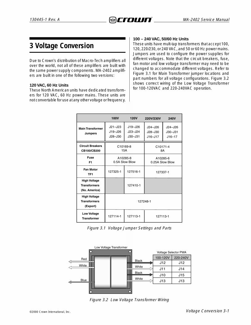
3 Voltage Conversion100 – 240 VAC, 50/60 Hz UnitsThese units have mult-tap transformers that accept 100,120, 220/230, or 240 VAC, and 50 or 60 Hz power mains.Jumpers are used to configure the power supplies fordifferent voltages. Note that the circuit breakers, fuse,fan motor and low voltage transformer may need to bechanged to accommodate different voltages. Refer toFigure 3.1 for Main Transformer jumper locations andpart numbers for all voltage configurations. Figure 3.2shows correct wiring of the Low Voltage Transformerfor 100-120VAC and 220-240VAC operation.
Figure 3.1 Voltage Jumper Settings and Parts
Figure 3.2 Low Voltage Transformer Wiring

MA-2402 Service Manual
3-2 Voltage Conversion
130445-1 Rev. A
©2000 Crown International, Inc.
This page intentionally left blank

Circuit Theory 4-1
130445-1 Rev. A MA-2402 Service Manual
©2000 Crown International, Inc.
4 Circuit Theory
4.1 OverviewIt should be noted that over time Crown makes improve-ments and changes to their products for various rea-sons. This manual is up to date as of the time of writing.For additional information regarding these amplifiers,refer to the applicable Technical Notes provided byCrown for this product.
This section of the manual explains the general opera-tion of a typical Crown grounded bridge power ampli-fier. Topics covered include Front End, GroundedBridge, and ODEP. Due to variations in design from vin-tage to vintage (and similarities with other Crown prod-ucts) the theory of operation remains simplified.
4.2 FeaturesMacro Tech amplifiers utilize numerous Crown innova-tions including grounded bridge and ODEP technolo-gies. Cooling techniques make use of the what is es-sentially air conditioner technology. Air flows bottom totop, and front to side. Air flows a short distance acrossa wide heatsink. Output transistors are of the metal cantype rather than plastic case. This allows for a signifi-cantly higher thermal margin for the given voltage andcurrent ratings. All devices used are tested and gradedto ensure maximum reliability. Another electronic tech-nique used is negative feedback. Almost all poweramplifiers utilize negative feedback to control gain andprovide stability, but Crown uses multiple nested feed-back loops for maximum stability and greatly improveddamping. Most Crown amplifiers have damping in ex-cess of 1000 in the bass frequency range. This feed-back, along with our compensation and ultra-low dis-tortion output topology, make Crown amplifiers supe-rior.
Features specific to the Macro Tech Series include threeseperate power transformers (one for each channel andone for low voltage), a full time full speed fan, slew ratelimiting, and Crown's “Quad-Mute” protection circuit formuting delay or protective action. This amplifier can op-erate in either a Bridged or Parallel Mono mode as wellas dual (stereo). A sensitivity switch allows selection ofinput voltage required for rated output. Level controlsare mounted on the front panel and are of the rotarytype. Front panel indicators let the user know the statusof the low voltage power supply (enable), an ODEP in-dicator for each channel which shows the reserve en-
ergy status, and a SPI/IOC indicator for each channelwhich indicates signal output and distortion. In general,the packaging of this model is designed for maximumwatt/price/weight/size value with user friendly features.
For additional details refer to the specification section,or to the applicable Reference Manual.
4.3 Front End OperationThe front end is comprised of three stages: BalancedGain Stage (BGS), Variable Gain Stage (VGS), and theError Amp. Figure 4.1 shows a simplified diagram of atypical front end with voltage amplification stages.
4.3.1 Balanced Gain Stage (BGS)Input to the amplifier is balanced. The shield may beisolated from chassis ground by an RC network to inter-rupt ground loops via the Ground Lift Switch. The non-inverting (hot) side of the balanced input is fed to thenon-inverting input of the first op-amp stage. The in-verting (negative) side of the balanced input is fed tothe inverting input of the first op-amp stage. A potenti-ometer is provided for common mode rejection adjust-ment. Electrically, the BGS is at unity gain. (From anaudio perspective, however, this stage actually provides+6dB gain if a fully balanced signal is placed on itsinput.) The BGS is a non-inverting stage. It’s output isdelivered to the Variable Gain Stage.
4.3.2 Variable Gain Stage (VGS)From the output of the BGS, the signal goes to the VGSwhere gain is determined by the position of the Sensi-tivity Switch, and level is determined by the level con-trol. VGS is an inverting stage with the input being fedto its op-amp stage. Because gain after this stage isfixed at 26 dB (factor of 20), greater amplifier sensitivityis achieved by controlling the ratio of feedback to inputresistance. The Sensitivity Switch sets the input imped-ance to this stage and varies the gain such that theoverall amplifier gain is 26 dB, or is adjusted appropri-ately for 0.775V or 1.4V input to attain rated output.
4.3.3 Error AmpThe inverted output from the VGS is fed to the non-in-verting input of the Error Amp op-amp stage throughan AC coupling capacitor and input resistor. Amplifieroutput is fed back via the negative feedback (NFb) loopresistor. The ratio of feedback resistor to input resistorfixes gain from the Error Amp input to the output of theamplifier at 26 dB. Diodes prevent overdriving the ErrorAmp. Because the Error Amp amplifies the differencebetween input and output signals, any difference in thetwo waveforms will produce a near open loop gain con-

MA-2402 Service Manual
4-2 Circuit Theory
130445-1 Rev. A
©2000 Crown International, Inc.
dition which in turn results in high peak output voltage.The output of the Error Amp, called the Error Signal (ES)drives the Voltage Translators.
4.4 Voltage AmplificationThe Voltage Translator stage separates the output ofthe Error Amp into balanced positive and negative drivevoltages for the Last Voltage Amplifiers (LVAs), translat-ing the signal from ground referenced ±15V to ±Vccreference. LVAs provide the main voltage amplificationand drive the High Side output stages. Gain from Volt-age Translator input to amplifier output is a factor of25.2.
4.4.1 Voltage TranslatorsA voltage divider network splits the Error Signal (ES)into positive and negative drive signals for the balancedvoltage translator stage. These offset reference voltagesdrive the input to the Voltage Translator transistors. Anested NFb loop from the output of the amplifier mixeswith the inverted signal riding on the offset references.This negative feedback fixes gain at the offset refer-ence points (and the output of the Error Amp) at a fac-tor of –25.2 with respect to the amplifier output. TheVoltage Translators are arranged in a common baseconfiguration for non-inverting voltage gain with equalgain. They shift the audio from the ±15V reference toVCC reference. Their outputs drive their respective LVA.
Also tied into the Voltage Translator inputs are ODEPlimiting transistors and control/protection transistors. TheODEP transistors steal drive as dictated by the ODEPcircuitry (discussed later). The control/protection tran-sistors act as switches to totally shunt audio to groundduring the turn-on delay, or during a DC/LF or Fault pro-tective action.
4.4.2 Last Voltage Amplifiers (LVAs)The Voltage Translator stage channels the signal to theLast Voltage Amplifiers (LVA’s) in a balanced configura-tion. The +LVA and -LVA, with their push-pull effectthrough the Bias Servo, drive the fully complementaryoutput stage. The LVAs are configured as commonemitter amplifiers. This configuration provides sufficientvoltage gain and inverts the audio. The polarity inver-sion is necessary to avoid an overall polarity inversionfrom input jack to output jack, and it allows the NFbloop to control Error Amp gain by feeding back to itsnon-inverting input (with its polarity opposite to the out-put of the VGS). With the added voltage swing providedby the LVAs, the signal then gains current amplificationthrough the Darlington emitter-follower output stage.
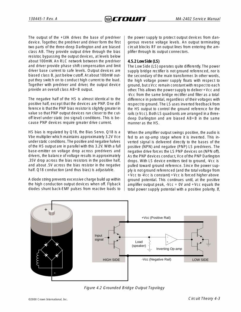
4.5 Grounded Bridge TopologyFigure 4.2 is a simplified example of the grounded bridgeoutput topology. It consists of four quadrants of threedeep Darlington (composite) emitter-follower stages perchannel: one NPN and one PNP on the High Side of thebridge (driving the load), and one NPN and one PNPon the Low Side of the bridge (controlling the groundreference for the rails). The output stages are biased tooperate class AB+B for ultra low distortion in the signalzero-crossing region and high efficiency.
4.5.1 High Side (HS)The High Side (HS) of the bridge operates much like aconventional bipolar push-pull output configuration. Asthe input drive voltage becomes more positive, the HSNPN conducts and delivers positive voltage to the load.Eventually the NPN devices reach full conduction and+Vcc is across the load. At this time the HS PNP is bi-ased off. When the drive signal is negative going, theHS PNP conducts to deliver –Vcc to the load and theHS NPN stage is off.
+
-
+
-
+
-
BGS VGS ErrorAmp
AudioInputs
Vol
tage
Div
ider
NFb Loop
+-ODEP
Mute
+15V
-15V
+VCC
-VCC
NPN Outputs (+HS)
PNP Outputs (-HS)
Q100
Q103
Q121
Q122
Q101
Q102
Q105
Q110
VoltageTranslators
LVA's
Figure 4.1 Typical Amplifier Front End and Voltage Amplification Stages.
Circuit Theory 4-3
130445-1 Rev. A MA-2402 Service Manual
©2000 Crown International, Inc.
The output of the +LVA drives the base of predriverdevice. Together, the predriver and driver form the firsttwo parts of the three-deep Darlington and are biasedclass AB. They provide output drive through the biasresistor, bypassing the output devices, at levels belowabout 100mW. An RLC network between the predriverand driver provide phase shift compensation and limitdriver base current to safe levels. Output devices arebiased class B, just below cutoff. At about 100mW out-put they switch on to conduct high current to the load.Together with predriver and driver, the output deviceprovide an overall class AB+B output.
The negative half of the HS is almost identical to thepositive half, except that the devices are PNP. One dif-ference is that the PNP bias resistor is slightly greater invalue so that PNP output devices run closer to the cut-off level under static (no signal) conditions. This is be-cause PNP devices require greater drive current.
HS bias is regulated by Q18, the Bias Servo. Q18 is aVbe multiplier which maintains approximately 3.2V Vceunder static conditions. The positive and negative halvesof the HS output are in parallel with this 3.2V. With a fullbase-emitter on voltage drop across predrivers anddrivers, the balance of voltage results in approximately.35V drop across the bias resistors in the positive half,and about .5V across the bias resistor in the negativehalf. Q18 conduction (and thus bias) is adjustable.
A diode string prevents excessive charge build up withinthe high conduction output devices when off. Flybackdiodes shunt back-EMF pulses from reactive loads to
the power supply to protect output devices from dan-gerous reverse voltage levels. An output terminatingcircuit blocks RF on output lines from entering the am-plifier through its output connectors.
4.5.2 Low Side (LS)The Low Side (LS) operates quite differently. The powersupply bridge rectifier is not ground referenced, nor isthe secondary of the main transformer. In other words,the high voltage power supply floats with respect toground, but ±Vcc remain constant with respect to eachother. This allows the power supply to deliver +Vcc and–Vcc from the same bridge rectifier and filter as a totaldifference in potential, regardless of their voltages withrespect to ground. The LS uses inverted feedback fromthe HS output to control the ground reference for therails (±Vcc). Both LS quadrants are arranged in a three-deep Darlington and are biased AB+B in the samemanner as the HS.
When the amplifier output swings positive, the audio isfed to an op-amp stage where it is inverted. This in-verted signal is delivered directly to the bases of thepositive (NPN) and negative (PNP) LS predrivers. Thenegative drive forces the LS PNP devices on (NPN off).As the PNP devices conduct, Vce of the PNP Darlingtondrops. With LS device emitters tied to ground, –Vcc ispulled toward ground reference. Since the power sup-ply is not ground referenced (and the total voltage from+Vcc to –Vcc is constant) +Vcc is forced higher aboveground potential. This continues until, at the positiveamplifier output peak, -Vcc = 0V and +Vcc equals thetotal power supply potential with a positive polarity. If,
+
-
+Vcc (Positive Rail)
-Vcc (Negative Rail)
Load(speaker)
Inputsignal
HIGH SIDE LOW SIDE
Inverting Op-amp
Figure 4.2 Grounded Bridge Output Topology
MA-2402 Service Manual
4-4 Circuit Theory
130445-1 Rev. A
©2000 Crown International, Inc.
for example, the power supply produced a total of 70Vfrom rail to rail (±35VDC measured from ground with nosignal), the amplifier output would reach a positive peakof +70V.
Conversely, during a negative swing of the HS outputwhere HS PNP devices conduct, the op-amp wouldoutput a positive voltage forcing LS NPN devices toconduct. This would result in +Vcc swinging towardground potential and – Vcc further from ground poten-tial. At the negative amplifier output peak, +Vcc = 0Vand – Vcc equals the total power supply potential with anegative polarity. Using the same example as above, a70V supply would allow a negative output peak of– 70V. In summary, a power supply which produces atotal of 70VDC rail to rail (or ±35VDC statically) is ca-pable of producing 140V peak-to-peak at the amplifieroutput when the grounded bridge topology is used. Thevoltage used in this example are relatively close to thevoltages of the MA-602.
The total effect is to deliver a peak to peak voltage tothe speaker load which is twice the voltage producedby the power supply. Benefits include full utilization ofthe power supply (it conducts current during both halvesof the output signal; conventional designs require twopower supplies per channel, one positive and one nega-tive), and never exposing any output device to morethan half of the peak to peak output voltage (which doesoccur in conventional designs).
Low side bias is established by a diode string whichalso shunts built up charges on the output devices. Biasis adjustable via potentiometer. Flyback diodes performthe same function as the HS flybacks. The output of theLS is tied directly to chassis ground via ground strap.
4.6 Output Device Emulation Protection(ODEP)To further protect the output stages, a specially devel-oped ODEP circuit is used. It produces a complex ana-log output signal. This signal is proportional to the al-ways changing safe-operating-area margin of the out-put transistors. The ODEP signal controls the VoltageTranslator stage by removing drive that may exceedthe safe-operating-area of the output stage.
ODEP senses output current by measuring the voltagedropped across LS emitter resistors. LS NPN current(negative amplifier output) and +Vcc are sensed, thenmultiplied to obtain a signal proportional to output power.Positive and negative ODEP voltages are adjustablevia two potentiometers. Across ±ODEP are a PTC anda thermal sense (current source). The PTC is essen-tially a cutoff switch that causes hard ODEP limiting ifheatsink temperature exceeds a safe maximum, regard-less of signal level. The thermal sense causes the dif-ferential between +ODEP and – ODEP to decrease asheatsink temperature increases. An increase in posi-tive output signal output into a load will result in – ODEPvoltage dropping; an increase in negative output volt-age and current will cause +ODEP voltage to drop. Acomplex RC network between the ±ODEP circuitry isused to simulate the thermal barriers between the inte-rior of the output device die (immeasurable by normalmeans) and the time delay from heat generation at thedie until heat dissipates to the thermal sensor. The com-bined effects of thermal history and instantaneous dy-namic power level result in an accurate simulation ofthe actual thermal condition of the output transistors.

Circuit Theory 4-5
130445-1 Rev. A MA-2402 Service Manual
©2000 Crown International, Inc.
NEGATIVELOW SIDEOUTPUT
PNP STAGE
POSITIVELOW SIDEOUTPUT
NPN STAGE
NEGATIVEHIGH SIDEOUTPUT
PNP STAGE
POSITIVEHIGH SIDEOUTPUT
NPN STAGE
HIGH SIDEBIAS
SERVO
+LVA-1
-LVA-1
+VOLTAGETRANSLATOR
-VOLTAGETRANSLATOR
OUTPUTDEVICE
EMULATIONPROTECTION
ERRORAMP
VGSBGS
BALANCEDINPUTS
INVERTINGBRIDGE
BALANCE
LOW SIDEBIAS
DIODESTRING
-1
-1
MAIN NEGATIVE FEEDBACK (NFb) LOOP
Figure 4.3 Typical Crown Grounded Bridge Amplifier Basic Block Diagram (One Channel Shown)

MA-2402 Service Manual
4-6 Circuit Theory
130445-1 Rev. A
©2000 Crown International, Inc.
This page intentionally left blank

Maintenance 5-1
130445-1 Rev. A MA-2402 Service Manual
©2000 Crown International, Inc.
5.1 Cautions and WarningsDANGER: The outputs of this amplifier can produceLETHAL energy levels! Be very careful when makingconnections. Do not attempt to change output wiringuntil the amplifier has been off at least 10 seconds.WARNING: This unit is capable of producing high soundpressure levels. Continued exposure to high sound pres-sure levels can cause permanent hearing impairmentor loss. User caution is advised and ear protection isrecommended when using at high levels.WARNING: Do not expose this unit to rain or moisture.WARNING: Only properly trained and qualified techni-cians should attempt to service this unit. There are nouser serviceable parts inside.WARNING: When performing service checks with thepower off, discharge the main power supply filter ca-pacitors fully before taking any measurements or touch-ing any electrical components. A 300-ohm 10-W resis-tor is recommended for this. Hold the resistor with pli-ers, as the resistor may become extremely hot.WARNING: Under load, with a sine wave signal at fullpower into both channels, the amplifier may draw inexcess of 30 amperes from the AC service mains.WARNING: Do not change the position of the ModeSwitch when the amplifier is turned on. If the position ofthis switch is changed while the amplifier is powered,transients may damage your speakers.WARNING: Heatsinks are not at ground potential. Si-multaneously touching either heatsink and ground, orboth heatsinks will cause electrical shock.CAUTION: Eye protection should be worn at all timeswhen protective covers are removed and the amplifieris plugged in.CAUTION: Disconnect the power cord before install-ing or removing any cover or panel.
5.2 General InformationThe following test procedures are to be used to verifyoperation of this amplifier. DO NOT connect a load orinject a signal unless directed to do so by the proce-dure. These tests, though meant for verification and
alignment of the amplifier, may also be very helpful introubleshooting. For best results, tests should be per-formed in order.
All tests assume that AC power is from a regulated ACsource appropriate for the unit under test.. Test equip-ment includes an oscilloscope, a DMM, a signal gen-erator, loads, and I.M.D. and T.H.D. noise test equip-ment.
5.3 Test Procedures5.3.1 Standard Initial ConditionsLevel controls fully clockwise.Stereo/Mono switch in Stereo.Sensitivity switch in 26 dB fixed gain position.Ambient Temperature: 20 to 30 degrees C.It is assumed, in each step, that conditions of the am-plifier are per these initial conditions unless otherwisespecified.
5.3.2 Output Bias AdjustmentSpec: 310 to 330mVDC.
Procedure: Perform procedure for each channel. Whilethe heatsink temperature is less than 40° C measurethe DC voltage on the output module across R09 (15ohm) or on the main module at TP100-7 (TP200-7 forchannel 2), adjust R02 if necessary. Measure the DCvoltage on the output module across R25 (15 ohm) oron the main module at TP100-8 (TP200-8 for channel2), adjust R33 if necessary.
5.3.3 ODEP Voltage AdjustmentSpec: 10.00V at 25 degrees C heat sink. See chart fortemperatures other than 25 degrees.
Procedure: Measure the heatsink temperature. If un-able to do so, note the room temperature and do thisprocedure while the heatsink temperature is at roomtemperature.
Measure the voltage on TP100-5 and adjust R186 forthe voltage per the chart. This voltage will be a nega-tive voltage. Measure the voltage on TP100-10 andadjust R300 for the voltage per the chart. This voltagewill be a positive voltage. For channel 2 the designa-tions are TP200-5, TP200-10, R286, and R400.
5 Maintenance
MA-2402 Service Manual
5-2 Maintenance
130445-1 Rev. A
©2000 Crown International, Inc.
ODEP Voltage ChartTolerance ±0.1V
°C °F Voltage
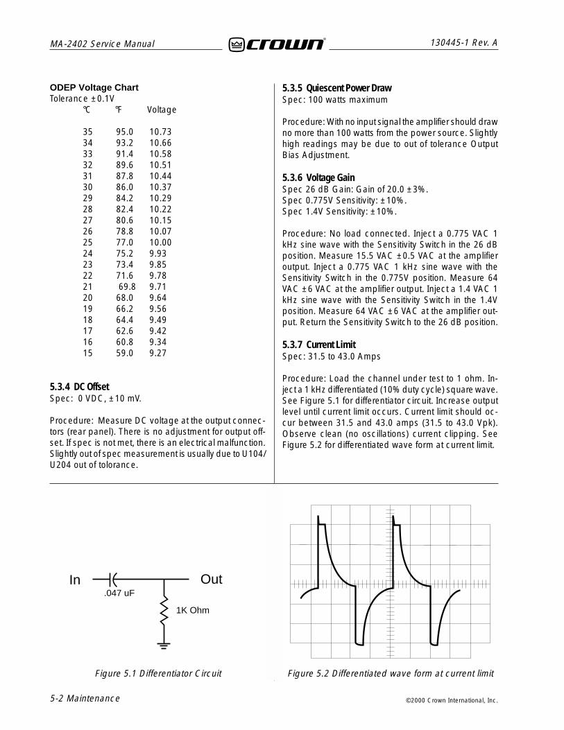
35 95.0 10.7334 93.2 10.6633 91.4 10.5832 89.6 10.5131 87.8 10.4430 86.0 10.3729 84.2 10.2928 82.4 10.2227 80.6 10.1526 78.8 10.0725 77.0 10.0024 75.2 9.9323 73.4 9.8522 71.6 9.7821 69.8 9.7120 68.0 9.6419 66.2 9.5618 64.4 9.4917 62.6 9.4216 60.8 9.3415 59.0 9.27
5.3.4 DC OffsetSpec: 0 VDC, ±10 mV.
Procedure: Measure DC voltage at the output connec-tors (rear panel). There is no adjustment for output off-set. If spec is not met, there is an electrical malfunction.Slightly out of spec measurement is usually due to U104/U204 out of tolorance.
5.3.5 Quiescent Power DrawSpec: 100 watts maximum
Procedure: With no input signal the amplifier should drawno more than 100 watts from the power source. Slightlyhigh readings may be due to out of tolerance OutputBias Adjustment.
5.3.6 Voltage GainSpec 26 dB Gain: Gain of 20.0 ±3%.Spec 0.775V Sensitivity: ±10%.Spec 1.4V Sensitivity: ±10%.
Procedure: No load connected. Inject a 0.775 VAC 1kHz sine wave with the Sensitivity Switch in the 26 dBposition. Measure 15.5 VAC ±0.5 VAC at the amplifieroutput. Inject a 0.775 VAC 1 kHz sine wave with theSensitivity Switch in the 0.775V position. Measure 64VAC ±6 VAC at the amplifier output. Inject a 1.4 VAC 1kHz sine wave with the Sensitivity Switch in the 1.4Vposition. Measure 64 VAC ±6 VAC at the amplifier out-put. Return the Sensitivity Switch to the 26 dB position.
5.3.7 Current LimitSpec: 31.5 to 43.0 Amps
Procedure: Load the channel under test to 1 ohm. In-ject a 1 kHz differentiated (10% duty cycle) square wave.See Figure 5.1 for differentiator circuit. Increase outputlevel until current limit occurs. Current limit should oc-cur between 31.5 and 43.0 amps (31.5 to 43.0 Vpk).Observe clean (no oscillations) current clipping. SeeFigure 5.2 for differentiated wave form at current limit.
In Out.047 uF
1K Ohm
Figure 5.1 Differentiator Circuit Figure 5.2 Differentiated wave form at current limit

Maintenance 5-3
130445-1 Rev. A MA-2402 Service Manual
©2000 Crown International, Inc.
.
5.3.8 10 kHz Square Wave ResponseSpec: No overshoot, ringing, or oscillations. Slew rate17 - 25 V/µS into 8 ohm load.
Procedure: Load the channel under test to 8 ohms. In-ject a 10 kHz square wave to obtain 35 volts zero-to-peak at the output. Observe the wave form. It must notinclude overshoot (<23mV), ringing, or any type of os-cillation. Rise time should be between 17 and 25 voltsper microsecond. See Figure 5.3 for typical 10 kHzsquare wave response.
5.3.9 CrosstalkSpec: 60 dB below 8 ohm rated power at 20 kHz, 85dB below 8 ohm rated power at 1 kHz and below.Initial Conditions: Per standard. Terminate input of chan-nel not driven with 600 ohms.
Procedure: Load each channel to 8 ohms. Inject a 20kHz sine wave into Channel 1 and increase the level to63 VAC at the output. Measure less than 63 millivoltsAC at the output of Channel 2. Inject a 1 kHz sine waveinto Channel 1 and increase the level to 63 VAC at theoutput. Measure less than 3.6 millivolts AC at the outputof Channel 2.Repeat for Channel 2 by driving channel2 and terminating Channel 1. Measure less than 63 mil-livolts at the output of Channel 1 at 20 kHz, and 3.6millivolts at 1 kHz.
5.3.10 Output PowerNorth America:Spec at 8 Ohm Stereo: >= 520W at 0.1% THD.Spec at 4 Ohm Stereo: >= 800W at 0.1% THD.Spec at 2 Ohm Stereo: >= 1050W at 0.1% THD.
International:Spec at 8 Ohm Stereo: >= 512W at 0.1% THD.Spec at 4 Ohm Stereo: >= 742W at 0.1% THD.Spec at 2 Ohm Stereo: >= 924W at 0.1% THD.
Procedure:North America: Load each channel to 8 ohms. Inject a1 kHz sine wave and measure at least 64.50 VAC at theoutput of each channel. Load each channel to 4 ohms.Inject a 1 kHz sine wave and measure at least 56.57VAC. Load each channel to 2 ohms. Inject a 1 kHz sinewave and measure at least 45.82 VAC. All power mea-surements must be at less than 0.1% THD.
International: Load each channel to 8 ohms. Inject a 1kHz sine wave and measure at least 64.0 VAC at theoutput of each channel. Load each channel to 4 ohms.Inject a 1 kHz sine wave and measure at least 54.5VAC. Load each channel to 2 ohms. Inject a 1 kHz sinewave and measure at least 43.0 VAC. All power mea-surements must be at less than 0.1% THD.
5.3.11 ODEP LimitingSpec: Clean limiting into a resistive load (see Figure5.4).
Procedure: Load each channel to 4 ohms. Inject a 50Hz sine wave into each channel and increase the levelfor 20 VAC at the output. Stuff a rag into the fan to pre-vent the fan from turning. Observe the wave form on anoscilloscope. After about 1 minute ODEP limiting willoccur (see Figure 5.4). Once limiting occurs the waveform will collapse at a rapid rate. Make sure both chan-nels limit. Remove the load and signal, remove the ragfrom the fan, and allow the amp to cool.
Figure 5.3 10 kHz square wave response Figure 5.4 ODEP limiting wave form

MA-2402 Service Manual
5-4 Maintenance
130445-1 Rev. A
©2000 Crown International, Inc.
5.3.12 Fan OperationSpec:Continuous full speed.
Procedure: Verify operation per above specification.
5.3.13 LF ProtectionSpec: Amplifier channel will cycle into protect with .5Hz 6Vp-p or 2 Hz 6 Vrms sine wave at the output.
Procedure: Inject a 2 Hz sine wave into the input of thechannel under test. Increase the level until the amplifiercycles on and off. It should cycle on and off when theoutput reaches approximately 6 Vrms.
5.3.14 Signal to NoiseSpec: 100 dB below rated 8 ohm power 20 Hz-20 kHz(A-weighted).
Procedure: Short inputs. Load each channel to 8 ohms.Measure less than 645 µV at the output of each chan-nel.
5.3.15 Intermodulation Distortion (IMD)Spec: 8 ohms, 0 dB = FTC continuous average 20 Hz-20 kHz power
0 dB < .01%–35 dB < .05%
Procedure: Load each channel to 8 ohms. Inject aSMPTE standard IM signal (60 Hz and 7 kHz sine wavemixed at 4:1 ratio). Set the 60 Hz portion of the signalfor 50.8 Vrms output. Set the 7 kHz portion to 25%. Withthe IM analyzer measure less than 0.01% IMD. Repeatthe test at –35 dB (reference 50.8 Vrms) and measureless than 0.05% IMD.
5.3.16 DisplaysSpec:
Enable - On when low voltage supply is on.ODEP - Dims in proportion to ODEP limiting.IOC - On with error amp clip (distortion).SPI - Flash in sync with amplifier output.
Procedure: Verify indicators per above specifications.
5.3.17 Post TestingAfter completion of testing, if all tests are satisfactory,the amplifier controls should be returned to the posi-tions required by the customer. If conditions are un-known or unspecified, factory settings are as follows:
Level Controls: 9 to 11 O’Clock.Sensitivity Switch: .775V.Stereo/Mono Switch: Stereo (Dual)Power: Off.

Parts 6-1
130445-1 Rev. A MA-2402 Service Manual
©2000 Crown International, Inc.
6.1 General InformationReplacement parts for this Crown amplifier can be or-dered from the Crown parts department.
PART PRICES AND AVAILABILITY ARE SUBJECTTO CHANGE WITHOUT NOTICE.
6.2 Ordering and Receiving PartsWhen ordering parts, be sure to give the product model,and include a description and part number from theparts listing. Price quotes are available on request.
6.2.1 TermsNormal terms are prepaid. Net-30 Days applies to onlythose having pre-established accounts with Crown. TheCrown Parts Department does accept Visa or MasterCard. If prepaying, the order must be packed andweighed before a total bill can be established, afterwhich an amount due will be issued and shipment madeupon receipt of payment. New parts returned for creditare subject to a restocking fee, and authorization fromthe Crown Parts Department must be obtained beforereturning parts for credit.
6.2.2 ShipmentShipment will normally be made via UPS, or best othermethod unless you specify otherwise. Shipments aremade to and from Elkhart, Indiana USA, only. Estab-lished accounts with Crown will receive shipment freightprepaid and will be billed. All others will receive ship-ment on a C.O.D. or prepayment (check or credit card)basis.
6 Parts
Crown Customer ServiceTechnical Support Group
Factory ServiceParts Department
Mailing Address: P.O. Box 1000, Elkhart IN 46515Shipping Address: Plant 2 S. W.
1718 W. Mishawaka Rd., Elkhart IN 46517Phone: (219) 294-8200
Toll Free: (800) 342-6939Fax: (219) 294-8301
http://www.crownaudio.com

MA-2402 Service Manual
6-2 Parts
130445-1 Rev. A
©2000 Crown International, Inc.
This page intentionally left blank

MA-2402 Service Manual130445-1 Rev. A
Exploded View Parts 7-1©2000 Crown International, Inc.
7.1 General InformationThis chapter includes a mechanical part list for thisproduct. All serviceable parts and assemblies will havea Crown Part Number (CPN) listed in this chapter. Theparts listed are current as of the date printed. Crownreserves the right to modify and improve its productsfor the benefit of its customers.
7 Exploded View Parts

MA-2402 Service Manual 130445-1 Rev. A
7-2 Exploded View Parts ©2000 Crown International, Inc.
Item Quantity Description Part # (CPN)
This page intentionally left blank

MA-2402 Service Manual130445-1 Rev. A
©2000 Crown International, Inc. Exploded View Parts 7-3
Figure 7.1 MA-2402 Chassis Assembly(Top)

MA-2402 Service Manual 130445-1 Rev. A
©2000 Crown International, Inc.7-4 Exploded View Parts
Item Quantity Description Part # (CPN) Item Quantity Description Part # (CPN)
1
2
3
4
5
6
7
8
9
10
11
12
13
14
15
16
17
18
19
20
21
22
23
24
25
26
27
28
29
30
31
32
33
34
35
36
37
38
1
1
1
1
1
2
2
2
2
2
2
2
2
2
5
1
2
8
1
2
2
2
1
2
2
2
8
1
4
1
2
2
2
2
1
1
1
1
CHAS, MA2402 WELD/AP/PC
PWA, MA PIP2 DISPLAY
5KOHM LNR 31 DETENT 15MM SHAFT POT
PANEL, MA DISPLAY AP SIL PC
OVERLAY,MA2402 DOM FP LEXAN
END CAP, D6271-5 PC SIL
SPACER, MA PNL CAP 245
PNL CAP D6271-7 PC SIL
6-32 X .75 FLTHD TT Z
HDL, C6713-9 PC SIL
6-32 X .18 CUP POINT MSCR BLK
KNOB, MA/MR SERIES
LEVEL CONTROL HARDWARE
LEVEL CONTROL HARDWARE
COLLAR, LED PLASTIC SILVER
PUSHBUTTON, .75 BEADED
FILTER, FR FOAM .53 X 16.7
VELCRO TAPE, MVA#8 1/2" X 1/4"
COLLAR, .35 ROUND PB SW
4-40 X .375 TAPTITE PAN PH
6-32 X .25 RDHD PH MSCR Z
SCR,#8X1.00 TYPE AB FLAT HD PH
EXTRU, D 8753-2 PC SIL
#8 X 5/16OD X 1/4L SPACER
.5 X .136 X .02 NYLON WASHER
CLIP, CT/MA/MT/PB FIL GRILLE
SEMS, 6-32X.31 TORX PNHD STAR
CVR, MA2400/3600 BTM PC
8-32 X 1.50 RDHD PH MSCR Z
SWITCH, DPST PUSHBTN 6A 250VAC
SILPAD, 2.87X14.57 7 MIL
HEATSINK ASSEMBLY
CAP SHELF ASSEMBLY
BREAKER
#8 INT STAR LOCKWASHER BLACK
8-32 X .37 RDHD BZ MSCR
JUMPER, TWO OTPT GROUND 215
6-32X.312 PAN HD T15 TT TYPE W
127105-2
SEE SECTION 8
C7280-8
F12887-0
127385-1
D8052J8
F12647-8
D8049J4
C10258-9
D8048J6
C6005-0
D6265-9
INCLUDED W POT
INCLUDED W POT
D7937-2
D6013-3
D7696-4
B5796-6
D4108-3
C5961-5
A10086-10604
A10103-10816
D8752-4
A10101-12
A10101-5
A10173-1
103433-70605
F12609-8
A10086-10824
C10180-5
D7796-2
SEE SECTION 8
SEE SECTION 8
SEE SECTION 3
A10094-5
A10086-70806
D8854-8
C9491-9
39
40
41
42
43
44
45
46
47
48
49
50
51
52
53
54
55
56
57
58
59
60
61
62
63
64
65
66
67
68
69
70
2
2
1
3
4
3
1
1
2
2
1
1
2
1
8
1
2
1
1
2
6
1
8
8
8
1
1
2
2
6
3
3
.750D X 5/8ID BUSHING
TERMINAL, DUAL BINDING POST W/HARDWARE
BP, MA2402 DOMESTIC
BP, MA2402 EXPORT (E13)
#6 INT STAR WASHER BLACK
SEMS, 6-32 X .31 TORX PNHD STAR
6-32X.312 PAN HD T15 TT TYPE W
STRAIN RELIEF, DOMESTIC
STRAIN RELIEF, EXPORT (E13)
PWR CORD, MA2402 DOMESTIC
PWR CORD, EUR PLUG CSL/PT#2 (E13CE)
8-32 X .37 RDHD BZ MSCR
#8 INT STAR LOCKWASHER BLACK
ASM, PIP2 FXQ
PWA, MA2402 CH2 RLT/V SELECT EXPORT
PWA, MA2402 DOMESTIC CH2 RELAY
7.5" CABLE TIE & CLAMP
PWA, MA2402 CH1 RLY/VSELECT
6-32X.312 PAN HD T15 TT TYPE W
FAN ASSEMBLY
6-32X.312 PAN HD T15 TT TYPE W
XFMR, LOW VOLTAGE
BRACKET, MA2402 LV XFMR MOUNT
6-32X.312 PAN HD T15 TT TYPE W
SEMS, 6-32 X .31 TORX PNHD STAR
CVR, MA MT PB CT TOP PC
10-32 X 2 PNHD PH MSCR Z
#10 INT TOOTH LOCKWASHER ZINC
#10 NYL SHLDR WASHER #10-375-A
WIRE, 16 BLU RING X 7.0 X FAST
WIRE, 16 RED RING X 7.0 X FAST
6-32X.312 PAN HD T15 TT TYPE W
TRANSFORMER, MA2402 MAIN 120V 60Hz
TRANSFORMER, MA2402 MAIN EXPORT
SEMS, 6-32 X .31 TORX PNHD STAR
SCREW, SOCKET CAP 6-32 X .437 BLK
#6 INT STAR WASHER ZINC
A10191-5
C10184-7
127106-1
128259-1
A10094-3
103433-70605
C9491-9
C7315-2
C10187-0
127510-1
A10793-0503M
A10086-70806
A10094-5
127256-1
SEE SECTION 8
SEE SECTION 8
C 1813-2
SEE SECTION 8
C9491-9
SEE SECTION 7.6
C9491-9
SEE SECTION 3
127309-1
C9491-9
103433-70605
D8501-5
A10089-11032
A10094-8
A10099-7
A11379-J070C
A11378-G070A
C9491-9
SEE SECTION 3
SEE SECTION 3
103433-70605
A10092-20607
A10094-4
7.2 Chassis Assembly (Top)Refer to figure 7.1 for Location of Major Parts
7.2 Chassis Assembly (Top) ContinuedRefer to figure 7.1 for Location of Major Parts

MA-2402 Service Manual130445-1 Rev. A
©2000 Crown International, Inc.
Figure 7.2 MA-2402 Chassis Assembly(Bottom)
Exploded View Parts 7-5
MA-2402 Service Manual 130445-1 Rev. A
©2000 Crown International, Inc.7-6 Exploded View Parts
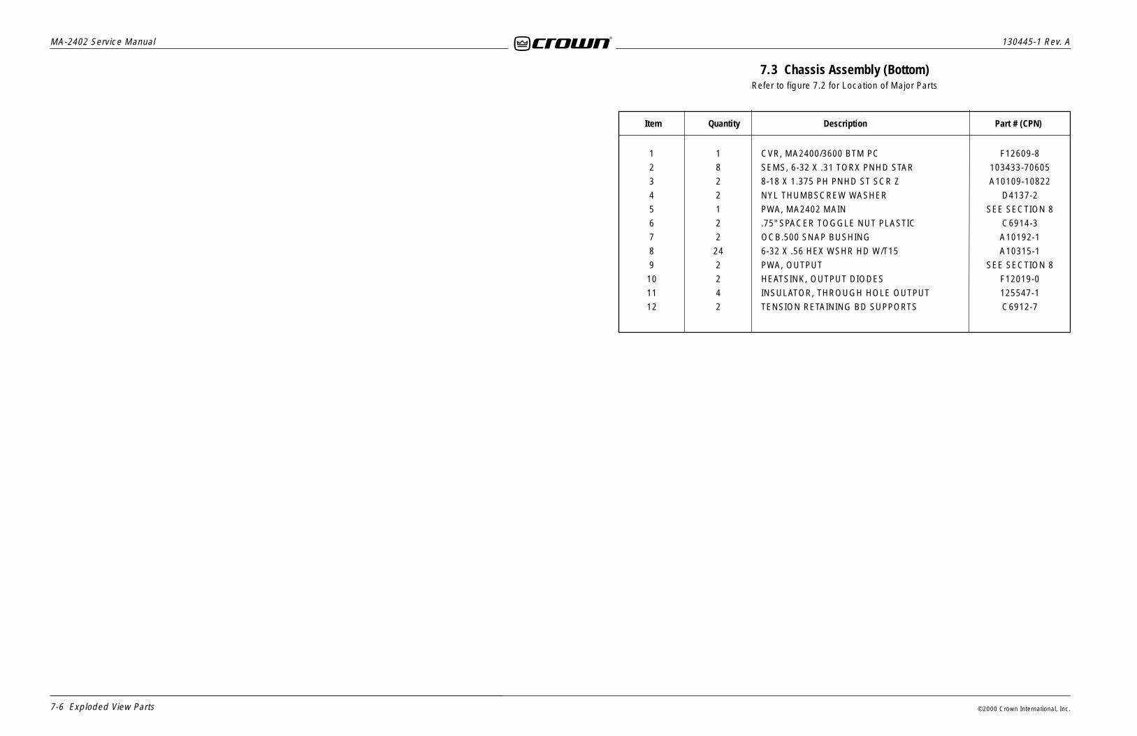
7.3 Chassis Assembly (Bottom)Refer to figure 7.2 for Location of Major Parts
1
2
3
4
5
6
7
8
9
10
11
12
1
8
2
2
1
2
2
24
2
2
4
2
CVR, MA2400/3600 BTM PC
SEMS, 6-32 X .31 TORX PNHD STAR
8-18 X 1.375 PH PNHD ST SCR Z
NYL THUMBSCREW WASHER
PWA, MA2402 MAIN
.75" SPACER TOGGLE NUT PLASTIC
OCB.500 SNAP BUSHING
6-32 X .56 HEX WSHR HD W/T15
PWA, OUTPUT
HEATSINK, OUTPUT DIODES
INSULATOR, THROUGH HOLE OUTPUT
TENSION RETAINING BD SUPPORTS
F12609-8
103433-70605
A10109-10822
D4137-2
SEE SECTION 8
C6914-3
A10192-1
A10315-1
SEE SECTION 8
F12019-0
125547-1
C6912-7
Item Quantity Description Part # (CPN)

MA-2402 Service Manual130445-1 Rev. A
Exploded View Parts 7-7©2000 Crown International, Inc.
Item Quantity Description Part # (CPN)
Figure 7.3 MA-2402 Heatsink Assembly
Item Quantity Description Part # (CPN)
7.4 Heat Sink Assembly(Channel 1 and 2 are Identical)
Refer to figure 7.3 for Exploded View
1
2
3
4
5
6
7
8
9
1
24
6
2
2
2
2
2
6
INS, 1.38 X 13.56 PAPER
6-32 X .312 PAN HD T15 TT TYPE W
SJ7147 PNP PWR XSISTOR
(Q08, Q09, Q10, Q16, Q17, Q18)
BRKT, TO3P HEATSINK
2SA1186 PWR PNP T03P SANKEN
(Q07, Q15)
CLIP, TO3P MOUNTING
HS, COP 3/4" FINS #7 SOLDER
2SC2837 PWR NPN TO3P SANKEN
(Q03, Q11)
SJ7148 NPN PWR XSISTOR
(Q04, Q05, Q06, Q12, Q13, Q14)
D8867-0
C9491-9
C8188-2
D 7666-7
C8573-5
D7665-9
M21322J8
C8574-3
C8187-4

MA-2402 Service Manual 130445-1 Rev. A
7-8 Exploded View Parts ©2000 Crown International, Inc.
Item Quantity Description Part # (CPN) Item Quantity Description Part # (CPN)
7.5 Cap Shelf Assembly(Channel 1 and 2 are Identical)
Refer to figure 7.4 for Exploded View
1
2
3
4
5
3
1
1
1
1
6-32X.312 PAN HD T15 TT TYPE W
CLIP, MA2402 RECTIFIER SPRING
PWA, MA2402 PIP2 CAP/RECT
SHELF, MA2402 CAP/RECT
TAPE, KAPTON(POLYIMIDE) 1/2 IN
C9491-9
127467-1
SEE SECTION 8
127111-1
S6251-3
Figure 7.4 MA-2402 Cap Shelf Assembly
MA-2402 Service Manual130445-1 Rev. A
Exploded View Parts 7-9©2000 Crown International, Inc.
Item Quantity Description Part # (CPN)
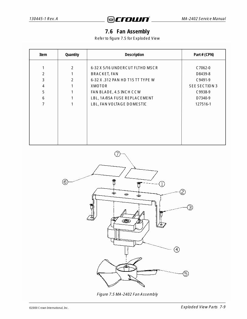
7.6 Fan AssemblyRefer to figure 7.5 for Exploded View
Item Quantity Description Part # (CPN)
Figure 7.5 MA-2402 Fan Assembly
1
2
3
4
5
6
7
2
1
2
1
1
1
1
6-32 X 5/16 UNDERCUT FLTHD MSCR
BRACKET, FAN
6-32 X .312 PAN HD T15 TT TYPE W
XMOTOR
FAN BLADE, 4.5 INCH CCW
LBL, 1A/05A FUSE REPLACEMENT
LBL, FAN VOLTAGE DOMESTIC
C7062-0
D8439-8
C9491-9
SEE SECTION 3
C9938-9
D7340-9
127516-1

MA-2402 Service Manual 130445-1 Rev. A
7-10 Exploded View Parts ©2000 Crown International, Inc.
Item Quantity Description Part # (CPN) Item Quantity Description Part # (CPN)
7.7 Standard PIP AssemblyRefer to figure 7.6 for Exploded View
Figure 7.6 Standard PIP Assembly
1
2
3
4
5
6
2
1
1
2
2
4
#8 X 1/4 #6 PNHD PH BZ
PWA, PIP2FXQ
PANEL, PIP2FXQ
PHONE JACK HARDWARE INCLD. W/ PHONE JACK
PHONE JACK HARDWARE INCLD. W/ PHONE JACK
M3 X .5 X 7MM PN HD BLK/NYLOK
C 7161-0
127210-1
127234-1
A10330-9
Module and Schematic Information 8-1
130445-1 Rev. A MA-2402 Service Manual
©2000 Crown International, Inc.
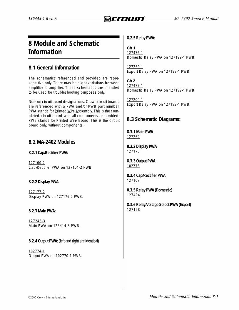
8.1 General Information
The schematics referenced and provided are repre-sentative only. There may be slight variations betweenamplifier to amplifier. These schematics are intendedto be used for troubleshooting purposes only.
Note on circuit board designations: Crown circuit boardsare referenced with a PWA and/or PWB part number.PWA stands for Printed Wire Assembly. This is the com-pleted circuit board with all components assembled.PWB stands for Printed Wire Board. This is the circuitboard only, without components.
8.2 MA-2402 Modules
8.2.1 Cap/Rectifier PWA:
127100-2Cap/Rectifier PWA on 127101-2 PWB.
8.2.2 Display PWA:
127177-2Display PWA on 127176-2 PWB.
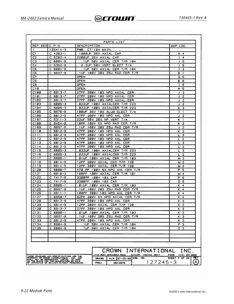
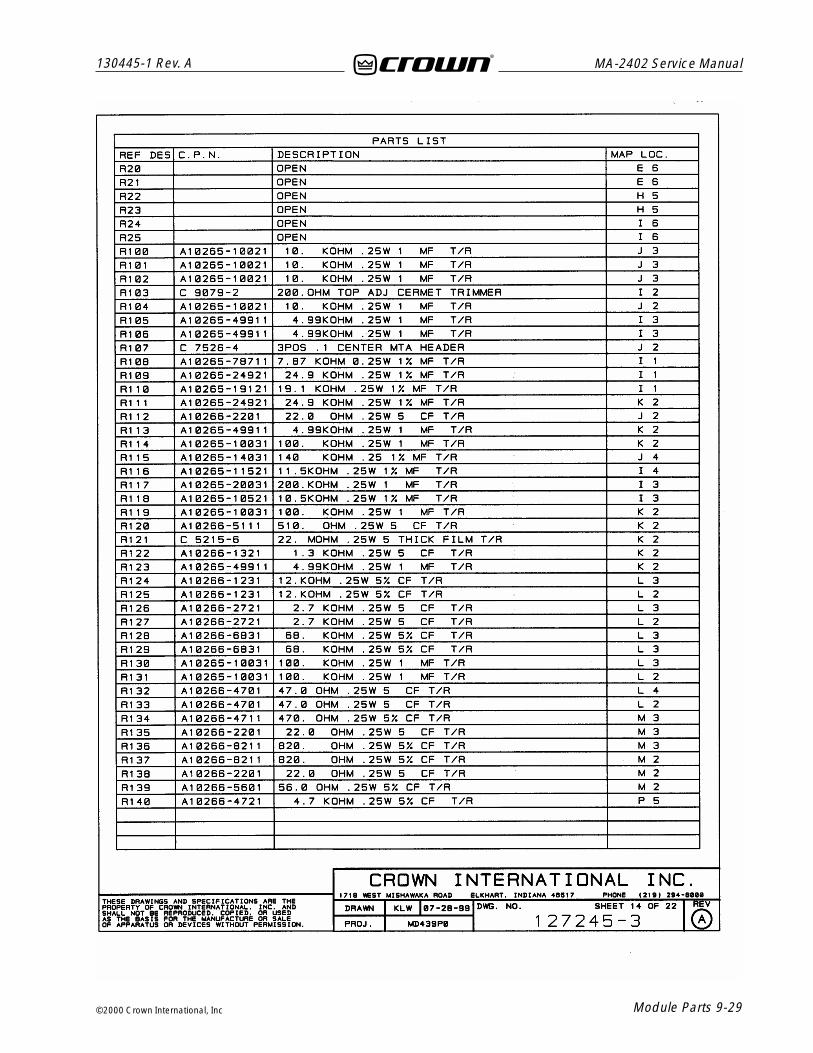
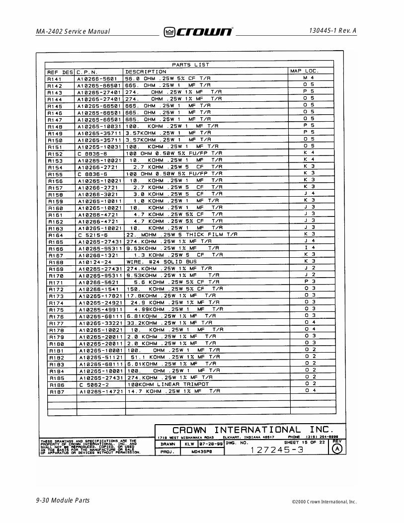
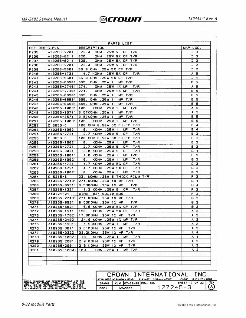
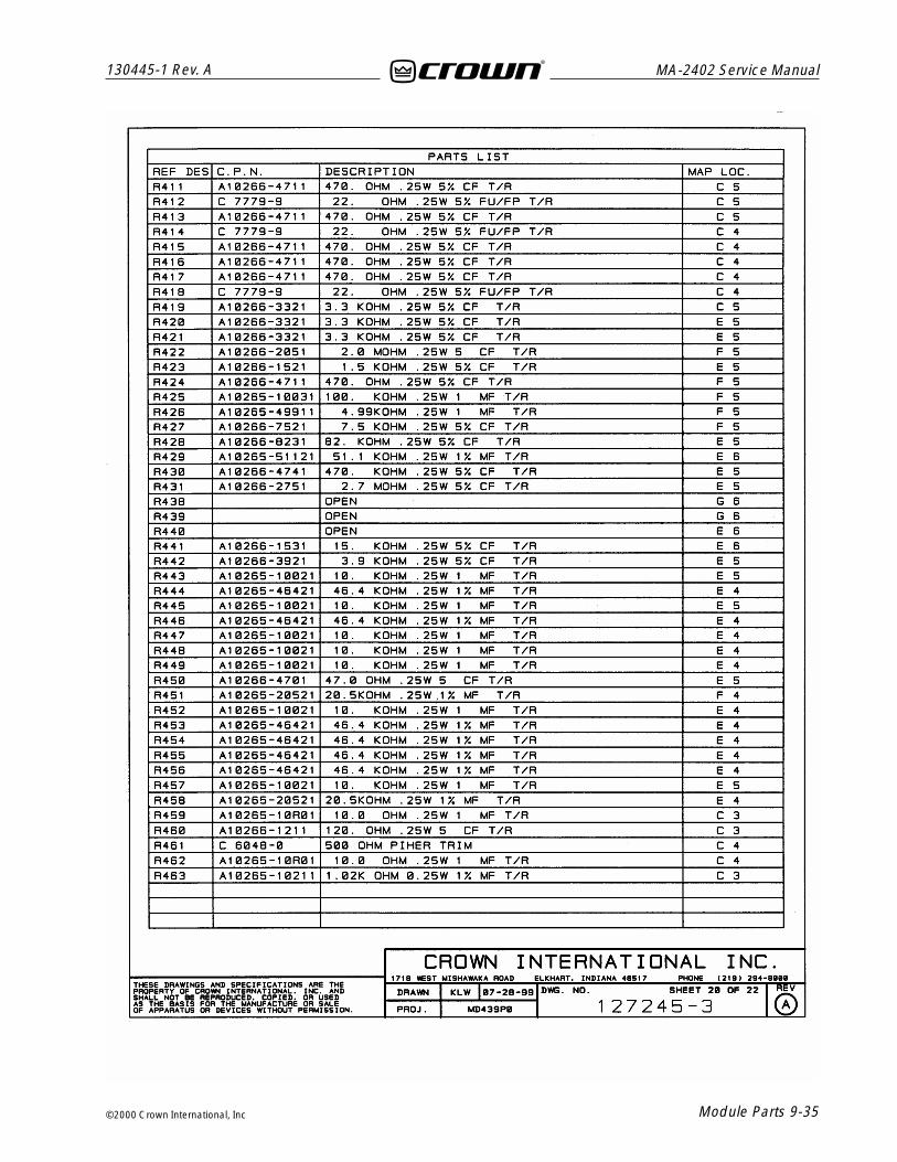
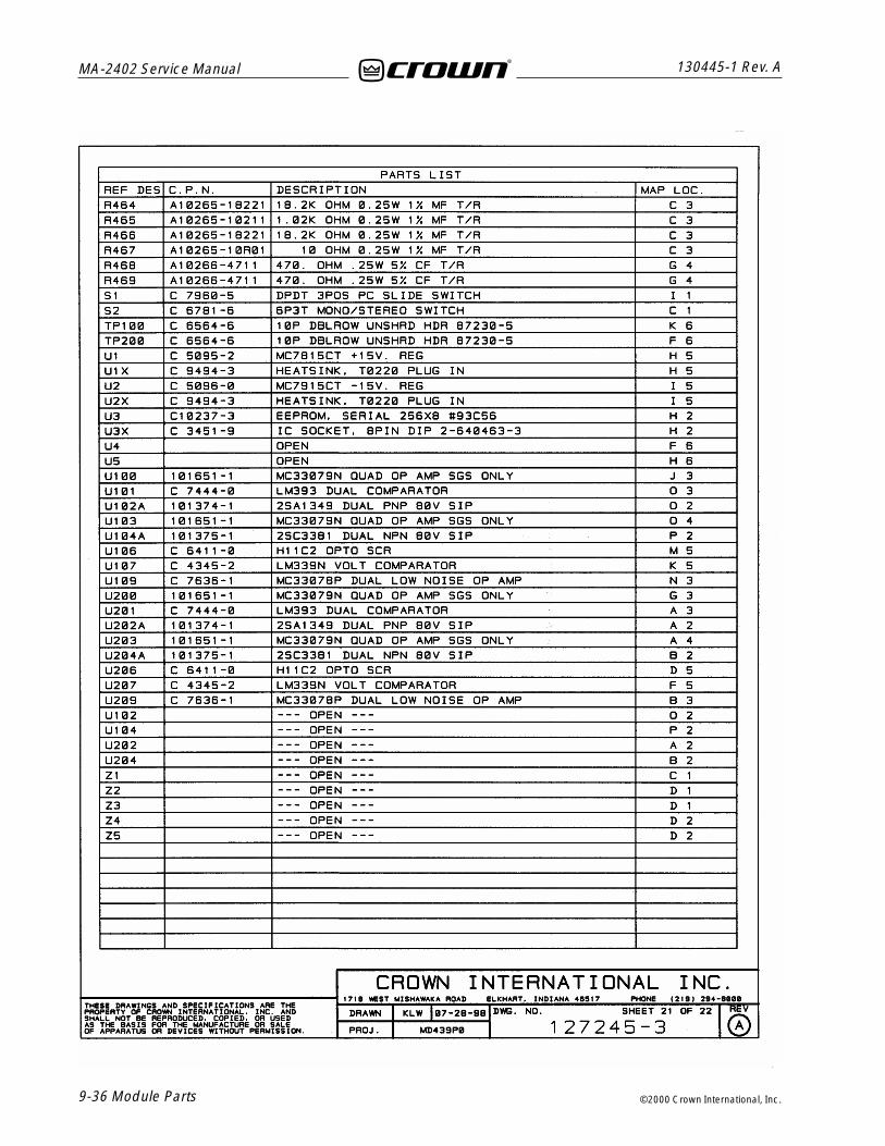
8.2.3 Main PWA:
127245-3Main PWA on 125414-3 PWB.
8.2.4 Output PWA: (left and right are identical)
102774-1Output PWA on 102770-1 PWB.
8.2.5 Relay PWA:
Ch 1127476-1Domestic Relay PWA on 127199-1 PWB.
127259-1Export Relay PWA on 127199-1 PWB.
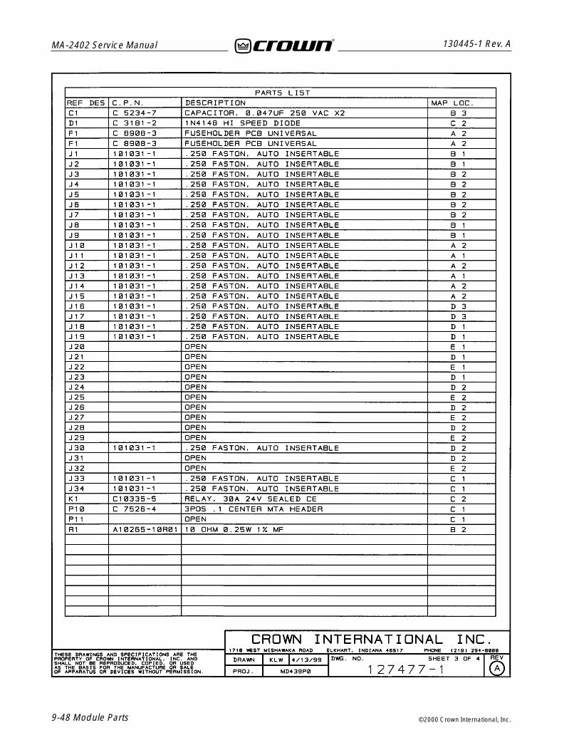
Ch 2127477-1Domestic Relay PWA on 127199-1 PWB.
127200-1Export Relay PWA on 127199-1 PWB.
8.3 Schematic Diagrams:
8.3.1 Main PWA127252
8.3.2 Display PWA127175
8.3.3 Output PWA102773
8.3.4 Cap/Rectifier PWA127108
8.3.5 Relay PWA (Domestic)127494
8.3.6 Relay/Voltage Select PWA (Export)127198
8 Module and SchematicInformation

MA-2402 Service Manual
8-2 Module and Schematic Information
130445-1 Rev. A
©2000 Crown International, Inc.
This page intentionally left blank

Module Parts 9-1
130445-1 Rev. A MA-2402 Service Manual
©2000 Crown International, Inc
9 Module Parts
9.1 General InformationThis chapter includes electrical parts lists for this prod-uct. All serviceable parts and assemblies will have aCrown Part Number (CPN) listed in this chapter. Theparts listed are current as of the date printed. Crownreserves the right to modify and improve its products forthe benefit of its customers. Please note: where refer-ence designations are listed as “installed on next as-sembly,” the CPN (Crown Part Number) for the associ-ated part may be found in Section 7, Exploded ViewParts.
102774-2127100-2127177-2127200-1127245-3127259-1127476-1127477-1

MA-2402 Service Manual
9-2 Module Parts
130445-1 Rev. A
©2000 Crown International, Inc.
This page intentionally left blank

Module Parts 9-3
130445-1 Rev. A MA-2402 Service Manual
©2000 Crown International, Inc

MA-2402 Service Manual
9-4 Module Parts
130445-1 Rev. A
©2000 Crown International, Inc.

Module Parts 9-5
130445-1 Rev. A MA-2402 Service Manual
©2000 Crown International, Inc

MA-2402 Service Manual
9-6 Module Parts
130445-1 Rev. A
©2000 Crown International, Inc.

MA–2402 Service Manual130445-1 Rev. A
©2000 Crown International, Inc. Module Parts 9-7
102774-2 PWA Component Map(Component Side)

MA– 2402 Service Manual 130445-1 Rev. A
©2000 Crown International, Inc.9-8 Module Parts
This Page Intentionally Left Blank

Module Parts 9-9
130445-1 Rev. A MA-2402 Service Manual
©2000 Crown International, Inc

MA-2402 Service Manual
9-10 Module Parts
130445-1 Rev. A
©2000 Crown International, Inc.

Module Parts 9-11
130445-1 Rev. A MA-2402 Service Manual
©2000 Crown International, Inc
127100-2 PWA Component Map (Component Side)

MA-2402 Service Manual
9-12 Module Parts
130445-1 Rev. A
©2000 Crown International, Inc.
This page intentionally left blank

Module Parts 9-13
130445-1 Rev. A MA-2402 Service Manual
©2000 Crown International, Inc

MA-2402 Service Manual
9-14 Module Parts
130445-1 Rev. A
©2000 Crown International, Inc.

Module Parts 9-15
130445-1 Rev. A MA-2402 Service Manual
©2000 Crown International, Inc

MA-2402 Service Manual
9-16 Module Parts
130445-1 Rev. A
©2000 Crown International, Inc.
127177-2 PWA Component Map (Component Side)
Module Parts 9-17
130445-1 Rev. A MA-2402 Service Manual
©2000 Crown International, Inc

MA-2402 Service Manual
9-18 Module Parts
130445-1 Rev. A
©2000 Crown International, Inc.
Module Parts 9-19
130445-1 Rev. A MA-2402 Service Manual
©2000 Crown International, Inc

MA-2402 Service Manual
9-20 Module Parts
130445-1 Rev. A
©2000 Crown International, Inc.
This page intentionally left blank

Module Parts 9-21
130445-1 Rev. A MA-2402 Service Manual
©2000 Crown International, Inc
MA-2402 Service Manual
9-22 Module Parts
130445-1 Rev. A
©2000 Crown International, Inc.

Module Parts 9-23
130445-1 Rev. A MA-2402 Service Manual
©2000 Crown International, Inc

MA-2402 Service Manual
9-24 Module Parts
130445-1 Rev. A
©2000 Crown International, Inc.

Module Parts 9-25
130445-1 Rev. A MA-2402 Service Manual
©2000 Crown International, Inc

MA-2402 Service Manual
9-26 Module Parts
130445-1 Rev. A
©2000 Crown International, Inc.

Module Parts 9-27
130445-1 Rev. A MA-2402 Service Manual
©2000 Crown International, Inc

MA-2402 Service Manual
9-28 Module Parts
130445-1 Rev. A
©2000 Crown International, Inc.
Module Parts 9-29
130445-1 Rev. A MA-2402 Service Manual
©2000 Crown International, Inc
MA-2402 Service Manual
9-30 Module Parts
130445-1 Rev. A
©2000 Crown International, Inc.

Module Parts 9-31
130445-1 Rev. A MA-2402 Service Manual
©2000 Crown International, Inc
MA-2402 Service Manual
9-32 Module Parts
130445-1 Rev. A
©2000 Crown International, Inc.

Module Parts 9-33
130445-1 Rev. A MA-2402 Service Manual
©2000 Crown International, Inc

MA-2402 Service Manual
9-34 Module Parts
130445-1 Rev. A
©2000 Crown International, Inc.
Module Parts 9-35
130445-1 Rev. A MA-2402 Service Manual
©2000 Crown International, Inc
MA-2402 Service Manual
9-36 Module Parts
130445-1 Rev. A
©2000 Crown International, Inc.

MA– 2402 Service Manual130445-1 Rev. A
©2000 Crown International, Inc. Module Parts 9-37
127245-3 PWA Component Map(Component Side)

MA– 2402 Service Manual 130445-1 Rev. A
©2000 Crown International, Inc.9-38 Module Parts
This Page Intentionally Left Blank

Module Parts 9-39
130445-1 Rev. A MA-2402 Service Manual
©2000 Crown International, Inc

MA-2402 Service Manual
9-40 Module Parts
130445-1 Rev. A
©2000 Crown International, Inc.

Module Parts 9-41
130445-1 Rev. A MA-2402 Service Manual
©2000 Crown International, Inc

MA-2402 Service Manual
9-42 Module Parts
130445-1 Rev. A
©2000 Crown International, Inc.
This page intentionally left blank

Module Parts 9-43
130445-1 Rev. A MA-2402 Service Manual
©2000 Crown International, Inc

MA-2402 Service Manual
9-44 Module Parts
130445-1 Rev. A
©2000 Crown International, Inc.

Module Parts 9-45
130445-1 Rev. A MA-2402 Service Manual
©2000 Crown International, Inc

MA-2402 Service Manual
9-46 Module Parts
130445-1 Rev. A
©2000 Crown International, Inc.
This page intentionally left blank

Module Parts 9-47
130445-1 Rev. A MA-2402 Service Manual
©2000 Crown International, Inc
MA-2402 Service Manual
9-48 Module Parts
130445-1 Rev. A
©2000 Crown International, Inc.

Module Parts 9-49
130445-1 Rev. A MA-2402 Service Manual
©2000 Crown International, Inc

MA-2402 Service Manual
9-50 Module Parts
130445-1 Rev. A
©2000 Crown International, Inc.
This page intentionally left blank

Schematics 10-1
130445-1 Rev. A MA-2402 Service Manual
©2000 Crown International, Inc
10 Schematics
102773127108127175127198127252127494
The schematics referenced and provided are repre-sentative only. There may be slight variations betweenamplifier to amplifier. These schematics are intendedto be used for troubleshooting purposes only.

MA-2402 Service Manual
10-2 Schematics
130445-1 Rev. A
©2000 Crown International, Inc.
This page intentionally left blank