macro and micro grouting process and the influence
TRANSCRIPT
Macro and micro grouting process and the influence mechanismof cracks in soft coal seam
Hui Yu1,2 • Housheng Jia2 • Shaowei Liu2 • Zhihe Liu1 • Baoyu Li1
Received: 4 October 2020 / Revised: 13 December 2020 / Accepted: 30 December 2020 / Published online: 26 January 2021
� The Author(s) 2021
Abstract Grouting is an important method to reinforce soft coal roadway, and the presence of primary cracks in the coal
body has an important influence on the grouting effect. With the discrete element simulation method, the grouting process of
the soft coal seam was simulated. The mechanism of primary cracks on grouting was revealed, while the influence of fracture
characteristics and grouting pressure on the grouting effect was analyzed. The results demonstrated that grouting in the soft
coal seam involves the stages of seepage, rapid splitting, slow splitting, and stability. Due to the presence of primary cracks,
the grouting diffusion radius increased significantly. Under the slurry pressure, the tensile stress concentration was formed at
the crack tip, and the slurry split the coal once the splitting pressure was reached. In addition, the distribution characteristics of
fractures are found to have a great influence on the grouting effect. It is observed that smaller fracture spacing is associated
with a larger slurry diffusion radius and thus easier penetration of the primary crack tips. The fracture angle affects the
direction of fracture propagation. The secondary fracture formed by splitting is a tensile fracture, which is more likely to
extend along the direction parallel to the maximum principal stress. Overall, these simulation results have guiding significance
for the setting of reasonable spacing of grouting holes in the practice of grouting engineering.
Keywords Discrete element simulation � Soft coal seam � Primary crack � Split grouting
1 Introduction
Deformation control of deep soft coal roadways is one of
the greatest challenges in the mining industry (Liu et al.
2018; Jiang et al. 2019, 2020; Zuo et al. 2019). For some
soft roadways, the grouting method can be used to rein-
force the roadways in order to maintain their stability
(Zhang et al. 2018; Stille et al. 2012; Xu et al. 2019).
Currently, in an attempt to establish a theoretical model of
grouting, researchers have developed the spherical
diffusion theory, cylindrical diffusion theory, carol theory,
Baker formula, and Lombardi formula, among others
(Lombardi and Deere 1993; Liu et al. 2019; Xiao et al.
2019; Chen et al. 2014). A large number of engineering
studies have reported that the splitting grouting process is
very complicated and is the result of fluid–solid coupling
between the seepage field and stress field (Zhang and
Shimada 2018; Rafi and Stille 2014; Wang et al. 2019;
Zhang et al. 2017; Liu and Sun 2019; Sha et al. 2019). The
diffusion form of grout in coal seam cracks is difficult to
obtain through laboratory tests or field measurements. The
particle flow simulation method has been applied in many
studies conducted in China and abroad (Sun et al.2010;
Geng et al.2012; Wang et al. 2020; Zhang et al. 2018; Lei
et al. 2016; Damjanac and Cundall 2016; Boschi et al.
2020; Koyama et al. 2013; Bandyopadhyay et al. 2020).
This method can reveal the mechanical law and coupling
mechanism of the grouting process from a microscopic
perspective, reflect the relationship between the
& Hui Yu
1 School of Resources and Environmental Engineering,
Shandong University of Technology,
Zibo 255000, Shandong, China
2 School of Energy Science and Engineering, Henan
Polytechnic University, Jiaozuo 454000, Henan, China
123
Int J Coal Sci Technol (2021) 8(5):969–982
https://doi.org/10.1007/s40789-020-00404-2

macroscopic performance of grouting and the microscopic
characteristics of the coal body, and simulate the crack
expansion under different grouting pressures.
However, the coal seam has various joints, cracks and
other structural planes, which have an important impact on
the mechanical properties of the coal seam. On the one
hand, cracks in the coal seam can serve as slurry flow
channels to reduce slurry diffusion resistance. On the other
hand, because of the weakening effect of cracks on the
strength of coal, the coal is more likely to split under
grouting pressure, which is conducive to slurry diffusion
(Gothall and Stille 2009; Jin et al. 2019; Jiang et al. 2018;
Deng et al. 2018; Xiao et al. 2017). Therefore, cracks in the
coal seam and their distribution characteristics have an
important influence on the grouting effect. At present, the
research on grouting engineering has mainly focused on the
influence of grouting pressure, permeability coefficient,
and other parameters on the grouting effect, while the
influence mechanism of primary cracks in the coal mass on
grouting has not been widely discussed (Kvartsberg and
Fransson 2013; Cheng et al. 2018; Bezuijen et al.2011;
Ajamzadeh et al. 2019; Hu et al.2019). In the present study,
through the discrete element simulation method, the
grouting process in soft coal seam was studied by micro-
scopic simulation. Furthermore, the influence of crack
characteristics and grouting pressure on grouting effect was
analyzed, and the action mechanism of the primary crack
on grouting was revealed.
2 Meso-model of grouting in soft coal seam
2.1 Engineering-geological characteristics of soft
coal seam
At present, a mine in Xinzheng city in Henan Province,
China, is mainly mining No. 21 coal seam. The coal at this
mine is soft, can be easily weathered and disintegrated, and
presents a loose form, with extremely low bearing capacity
and an average compressive strength of approximately
0.8 MPa. The coal seam has a simple structure and belongs
to the lean coal category.
The transport lane from working face 12209 in No. 21
coal seam revealed the SF19 normal fault (drop, 0 – 14 m).
The fault obliquely intersects with the working face road-
way along the strike SE87 degree, which is the main fault
structure affecting the working face. There are many sec-
ondary structures nearby that are influenced by faults,
which make the primary cracks in the coal body more
developed, as shown in Fig. 1. In order to prevent damage
to the roadway due to dynamic pressure during mining,
grouting reinforcement is applied to the whole section of
the enlarged roadway.
2.2 Particle flow simulation theory of coal seam
grouting
Grouting in the coal body is a complicated coupling pro-
cess between the slurry and coal body. The particle flow
method was used to analyze the stress of the meso element.
Whether the meso element was damaged or not was
assessed according to the fracture criterion of the meso
element. If the meso element is damaged, fractures will be
generated. The propagation of micro-fractures forms the
flow channel of the slurry. Thus, the grouting mechanism
can be clarified according to the micro-level.
2.2.1 Basic principle of fluid–solid coupling
The theory of fluid–solid coupling of particles is based on
specific basic assumptions, that is, the injected medium is
simulated by the aggregate of particles. The interaction and
movement of particles follow Newton’s law of motion;
however, there is no real fluid in the medium, which is
simulated by the ‘‘fluid field’’ of storage pressure. The
‘‘fluid domain’’ consists of a series of closed particle
chains, in which the stored pressure acts as an equivalent
body force on the surrounding particles. The movement of
simulated fluid in the injected medium is realized by a
‘‘pipeline’’, which is a parallel gap built on the tangent
position of the particles. Its internal space is then deter-
mined by the normal displacement of the contact point of
particles, and is considered as the position for simulating
fluid flow. According to the particle flow method, the fluid–
solid coupling is realized by the pressure stored in the fluid
domain acting on the particles on both sides through the
‘‘pipe’’, resulting in the relative movement of particles. The
size of the ‘‘pipe’’ changes due to the alteration in the
normal displacement between particles, which then leads to
the change of the ‘‘fluid domain’’ volume, thus realizing
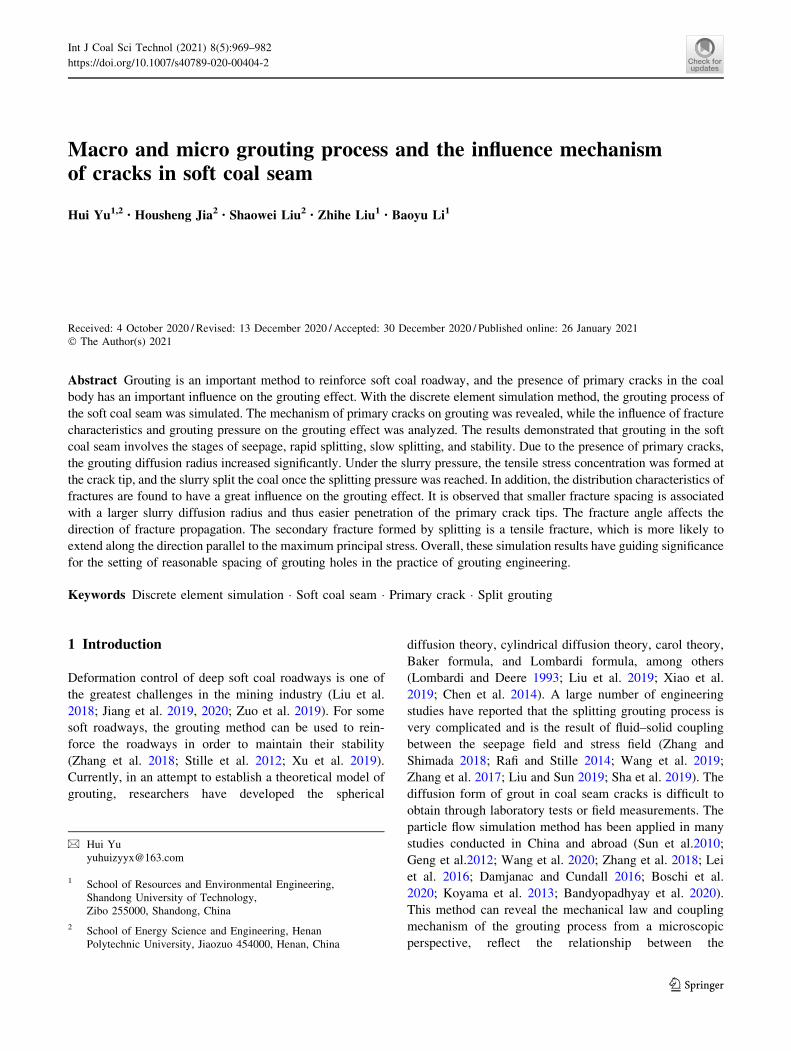
the fluid–solid interaction process. In Fig. 2, the red dots
Fig. 1 Coal bodies with primary cracks
970 H. Yu et al.
123
represent the domain, the black lines of the connecting
domain represent the ‘‘pipes’’ for fluid flow, and the blue
circles represent the coal particles.
2.2.2 Flow and pressure equations
Fluid is stored in the pore grid, and fluid exchange can
occur under the action of fluid pressure difference in
adjacent pore grids. In order to quantitatively calculate the
flow rate during fluid exchange, it can be assumed that the
fluid channel is a parallel plate channel at the contact point
of two adjacent particles. The flow rate between the two
pores can be expressed according to the Hagen-Poiseuille
equation, as follows:
q ¼ ka3DpL
ð1Þ
where, q is the flow rate in m3/s, a represents the opening
of the fluid passage and is related to the normal force of the
two particles, k is the permeability coefficient, Dp is the
pressure difference between the two pore grids, and L is the
fluid passage length.
In the Dt time step, the pore fluid pressure change
caused by fluid flow is calculated by the volume com-
pression modulus of the fluid. A certain pore is considered
to have n fluid channels. In the Dt time step, the total fluid
flow isP
q , and the change in the pore fluid pressure is
calculated as follows:
Dp¼Kf
Vd
XqDt � DVd
� �ð2Þ
where, Kf represents the compression modulus of the fluid,
and Vd is the pore volume.
2.3 Establishment of grouting model for soft coal
seam
In the particle flow simulation, the mechanical parameters
used in the model are the micro-mechanical parameters of
particles. Different micro-mechanical parameters of parti-
cles have a different effect on the macro-mechanical
properties of the coal body. By continuously adjusting the
micro-mechanical parameters of the particle body and
contact, simulation results that are close to the real macro-
mechanical properties of the coal body can be obtained. In
the present study, laboratory tests were firstly carried out
on coal samples obtained from the transportation lane of
the working face 12209 in order to obtain the macroscopic
physical and mechanical parameters of the soft coal body.
Next, simulation tests were conducted multiple times to
obtain the microscopic parameters of the particle aggre-
gate, consistent with the macroscopic parameters, as shown
in Tables 1 and 2. According to the particle flow method,
the real fluid is simulated by the ‘‘fluid domain’’ of storage
pressure. By performing several Darcy seepage experi-
ments, the basic parameters of the fluid domain were
obtained, as shown in Table 3.
Subsequently, in order to analyze the influence of pri-
mary cracks on the grouting diffusion characteristics of the
coal mass, models were respectively established for the
cases of absence or presence of primary cracks. The dif-
fusion process of coal seam grouting was explored from the
macro and micro perspectives, and the influence mecha-
nism of coal seam primary cracks on grouting was deter-
mined. In the actual coal body, the crack dip angle and
crack spacing are not represented by a single value, which
are usually in line with the normal distribution. However,
in order to facilitate the quantitative analysis of the influ-
ence of fracture distribution on the slurry diffusion, the
primary cracks were arranged regularly, as shown in Fig. 3.
In Case I, there were no primary cracks in the coal body.
By contrast, in Case II, primary cracks were present in the
coal body, with a crack spacing (D) of 0.5 m and a crack
angle (a) of 60�. The width 9 height of the two models
was 2 m 9 2 m, and the grouting pressure of the grouting
hole was 1.5 MPa. The boundary of the calculation model
is set as impermeable boundary. The smooth joint model
was used to simulate the primary cracks of the coal body,
and the parameters were shown in Table 4. A parallel bond
model was adopted to explore the contact between the
particles, which could not only simulate the normal and
tangential forces between the coal particles, but also sim-
ulate the rotation and bending moment between these
particles.
Fig. 2 Fluid domain and particle coupling
Macro and micro grouting process and the influence mechanism of cracks in soft coal seam 971
123

3 Results of grouting simulation of soft coal seam
3.1 Analysis of grouting process
The splitting grouting diffusion process is shown in Fig. 4
under a grouting pressure of 1.5 MPa and with the increase
in grouting time. The red line segments in figures indicate
that the bonds between particles are broken and that
splitting cracks are formed by coal grouting. Black circles
1, 2 and 3 represent monitoring circles with a radius of
0.25, 0.5 and 0.75 m, respectively. Each monitoring circle
was set to monitor the evolution law of porosity and coal
stress in the circle during grouting and was used as a
measure of the slurry diffusion radius. Figure 5 shows the
evolution of the internal porosity of the coal body with time
for the two cases investigated, with the dotted line repre-
senting Case I and the solid line representing Case II.
As shown in Figs. 4 and 5, with the increase in grouting
time, the distribution range of cracks in the coal seam
gradually increased, and the slurry diffusion process can be
divided into the following three stages:
(1) Slurry infiltration stage (step = 100): In the initial
stage, the grouting pressure had a compaction impact
on the coal medium surrounding the grouting hole
and resulted in the plastic damages in coal (Fig. 4a).
However, the slurry could not split the coal medium
over this stage and the fracture damages are mainly
gathering around the pipe hole. As observed in
Fig. 4, the porosity of the coal mass slightly
increased, and the diffusion radius of the slurry
reached 0.15 m.
(2) Rapid splitting stage of slurry (step = 100 – 1000):
With further progression of the grouting process, the
splitting effect was generated when the splitting
pressure was reached in the coal seam (Fig. 4b). The
slurry flowed rapidly along the splitting surface, and
the porosity increased rapidly. when the new gener-
ated cracks in Case II connected with its primary
cracks, the slurry diffusion radius had a signification
difference between two cases that the maximum
radius in Case I reached 0.3 m over 500 steps and the
radius in Case II increased from 0.5 m to 0.7 m after
the connection of the new and primary cracks.
(3) Slow splitting-stabilization stage (step more
than 1000): The slurry flowed and diffused along
the fracture under a certain grouting pressure gradi-
ent. After the rapid grouting stage, the splitting effect
on the coal seam was weakened as the pressure of
the slurry that was far away from the grouting hole
gradually decreased, and finally the fracture expan-
sion was relatively stable and no longer developing
to the deep part. The maximum diffusion radius of
the slurry was 0.8 m in Case II, while the porosity in
the monitoring circle slightly increased at this stage.
As shown in Fig. 5, the grouting porosity under the
conditions of Case II was larger than that in Case I, indi-
cating that more crack channels were generated under Case
II. Monitoring circle 1 had the largest porosity, indicating
that more cracks were produced closer to the grouting hole.
Table 1 Macroscopic parameters of coal particles
Modulus of elasticity E (GPa) Internal friction angle u (�) Cohesion C (MPa) Poisson’s ratio k Density (g/cm3)
2.2 34 1.3 0.25 1.8
Table 2 Mesoscopic parameters of coal particles
Particle minimum
radius Rmin (m)
Ratio of particle
radius Rmax/ Rmin
Friction
coefficient
Normal bond
strength (MPa)
Tangential bond
strength (MPa)
Normal contact
stiffness kn (MN/m)
Particle
stiffness ratio
kn/ks
Density
(g/cm3)
0.01 1.5 0.4 0.3 0.3 100 1.5 1.8
Table 3 Basic parameters of fluid domain
Apparent volume of domain
Vd (mm3)
Number of pipes in a
domain NPipe diameter
a (mm)
Fluid bulk modulus Kf
(GPa)
Permeability coefficient
k (cm/s)
Time step
4t (s)
1 2 1 1 0.1 0.001
972 H. Yu et al.
123

With the splitting flow of slurry, the porosity changed from
rapid growth to slow growth, and finally reached stability.
The evolution of the contact force inside the coal during
grouting is displayed in Fig. 6. The color of the lines in the
figure represents the magnitude of the contact force. The
contact force inside the coal body can reveal the com-
pression effect of grout pressure on the coal body and
reflect the distribution characteristics of the grout pressure.
Furthermore, the white area in the figure represents the
crack channel generated by grouting. Due to the squeezing
effect of slurry in the crack on the coal body, the contact
force between the cracks was relatively high. As shown in
Fig. 6, the grouting pressure range gradually expanded
outward from the grouting hole, while the highest pressure
was observed around the grouting hole, decreasing gradu-
ally along the radial direction. As the grouting time
increased, the maximum contact force also gradually
increased and finally tended to be stable. The maximum
contact force in Case I was increased from 30.6 to 50.6 kN.
In Case II, on the side of the primary crack facing away
from the grouting hole, the contact force was evidently
reduced, and a weak contact force zone appeared. The main
contact force was distributed radially (Fig. 6d), which
indicates that the void generated by the primary crack
damaged the integrity of the coal body and hindered the
transmission of the contact force.
According to the abovementioned observations, it was
evident that when the coal seam contained more primary
cracks, the slurry diffusion characteristics were quite dif-
ferent from those of the whole coal body. In Case II, with
the increase in grouting time, the secondary fractures
generated by coal seam splitting were connected with the
primary cracks. The sequence number in Case II displayed
in Fig. 4d represents the sequence of the fracture genera-
tion. The penetration position � (Fig. 4d) was always
located at the crack tip. Stress concentration was easily
produced at the crack tip, resulting in easier splitting. Due
to the small flow resistance of the slurry in the crack, the
slurry would flow along the primary cracks and continue to
split the coal seam at the other tip of the cracks. The dif-
fusive radius of grouting markedly increased in the pres-
ence of primary cracks, increasing from 0.65 m to more
than 0.76 m compared with Case I.
3.2 Stress field change of grouting coal
The stress field of coal body is the macro performance of
the contact force of particles. The average stress r in a
measurement region of volume V is computed as
(Christoffersen et al. 1981):
r¼ � 1
V
X
Nc
FðcÞ�LðcÞ ð3Þ
Fig. 3 Discrete element model of grouting in soft coal seam
Table 4 Parameters of smooth joint model
Normal stiffness (MN/m) Shear stiffness (MN/m) Friction coefficient Cohesion (MPa) Tensile strength (MPa) Crack apertures (mm)
2000 2000 0.35 0 0 1
Macro and micro grouting process and the influence mechanism of cracks in soft coal seam 973
123

where Nc is the number of contacts that lie in the mea-
surement region or on its boundary, F(c) is the contact force
vector, L(c) is the branch vector joining the centroids of the
two bodies in contact, � denotes outer product, and com-
pressive stress is negative by convention.
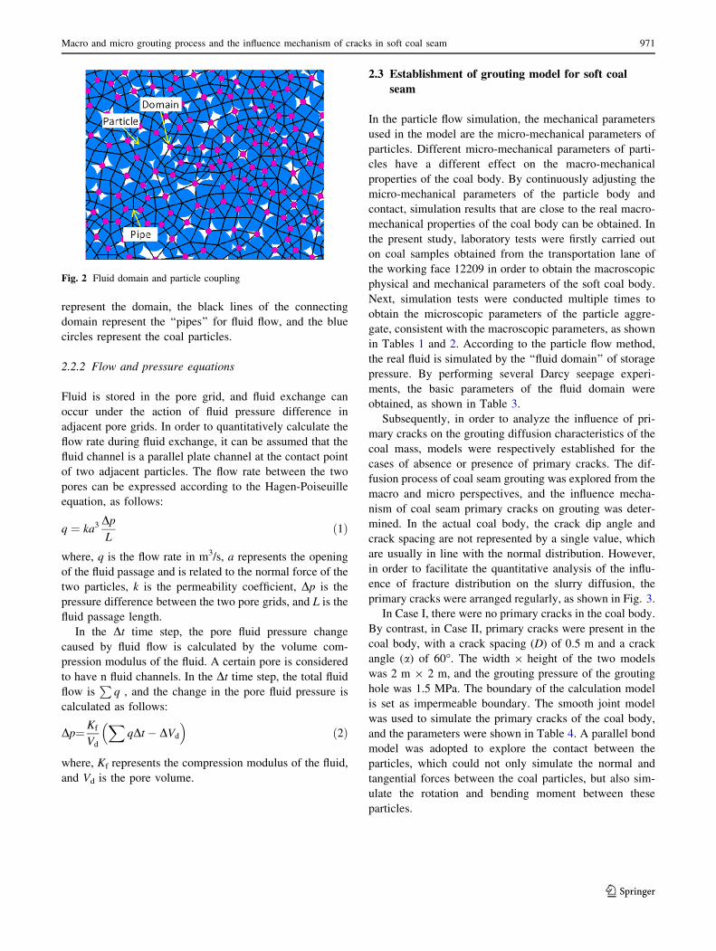
Stress curves for the three monitoring circles during
grouting are shown in Fig. 7. It can be seen from the fig-
ure that the normal stress and shear stress of Case II were
higher than those of Case I under the same conditions,
which indicates that grouting was more effective in Case II.
Among the three monitoring circles, the value of normal
stress was the highest for monitoring circle 1, indicating
that the closer to the grouting hole, the denser the slurry
distribution, and the greater the compressive stress on the
coal body. There are three distinct stages of stress change
in grouting process, including the rapid stress rising stage
(0–2000 steps), slow stress rising stage (2000–4000 steps)
and stress stabilization stage ([ 4000 steps).
During the period of rapid stress rise, the slurry splitting
fracture expanded rapidly, which is considered as the main
stage of the grouting process. The stress between particles
increased sharply, with more intense stress value changes
were observed closer to the grouting hole. With the
development of a split fracture to the deep coal body, the
pressure of the slurry in the fracture gradually decreased.
The splitting effect on the coal body was also gradually
weakened, and the stress was slowly raised. Finally, when
the slurry hydraulic pressure gradually decreased to less
than the splitting pressure, the stress between coal particles
did not change with time, and the grouting process tended
to be stable. When comparing the normal stress and shear
stress curves, it can be observed that the normal pressure
was much larger than the shear stress, indicating that the
compression deformation of coal particles was mainly
caused by mutual extrusion during the grouting process,
while the slip and stagger deformation of particles was
relatively small.
Fig. 4 Diffusion process of grouting in soft coal seam
0 2 4 6 80.110
0.111
0.114
0.115
Poro
sity
Calculation step (103)
Monitoring circle 1 Monitoring circle 2 Monitoring circle 3
Case I
Case II
Fig. 5 Porosity evolution process in different monitoring circles
974 H. Yu et al.
123

3.3 Strain rate change of grouting coal
The x-direction strain rate curve of the coal particles in
different monitoring ranges is presented in Fig. 8. In this
figure, the change of the strain rate of coal reflects the
speed of grouting. The variation trend of the strain rate of
the coal body in different monitoring ranges shown in the
figure was basically the same. In the same monitoring
range, the strain rate of Case II was higher than that of Case
I, indicating that grouting in Case II was more effective.
During the initial stage of grouting, the strain rate was high,
slurry splitting and rapid diffusion were observed, after
which the strain rate decreased gradually, indicating that
the slurry diffusion rate slowed down gradually and finally
tended to be stable. The maximum strain rate in the mon-
itoring circle 1 was 0.54, while the maximum strain rate in
monitoring circle 3 was only 0.06, which indicated that the
slurry diffusion gradually decreased from the grouting hole
to the surrounding area.
3.4 Analysis of the crack mechanism of grouting
in the coal seam
The formation of grouting fractures is due to the splitting
force of grouting fluid on the coal body. In order to study
the splitting of the primary crack tip under grouting, the
stress at the tip was monitored by investigating points A-D
that are shown in Fig. 9. The radius of the points is 0.03 m.
The internal contact force at step = 500 is displayed in
Fig. 9a, where the blue line represents the compressive
stress, and the brown line represents the tensile stress. In
addition, the internal tensile stress at step = 2000 is shown
in Fig. 9b. Since the fracture propagation is mainly asso-
ciated with the tensile stress, only the distribution charac-
teristics of the tensile stress are shown. At the periphery of
the grouting hole, a tensile stress ring was formed, which
surrounded the crack generated by the grouting. At the
newly formed secondary crack at the tip of the primary
crack, tensile stress concentration was also generated.
Therefore, the tensile stress at the tip of the crack is con-
sidered as the driving force for further expansion of the
crack.
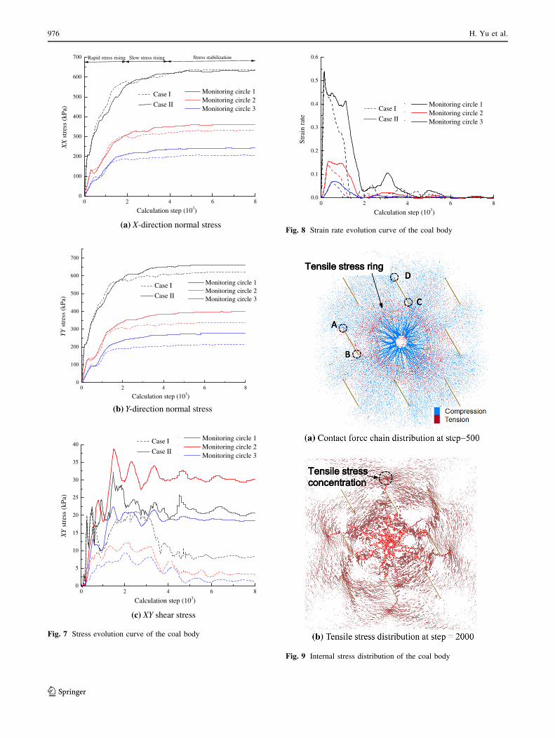
The stress evolution curve at the fracture tip is presented
in Fig. 10, where negative values represent the tensile
stress. The A and B tip curves represent the y-direction
stress, while the C and D tip curves represent the x-direc-
tion stress. According to the graph, the maximum tensile
stress at the crack tip C was higher than that at the D point,
which indicates that the energy of the slurry was gradually
weakened after flowing through the primary crack, and its
ability in splitting the coal seam was further weakened.
When the maximum tensile stress was less than the tensile
strength between particles, the coal seam could not be
further split by the slurry, and thus the grouting stopped.
Fig. 6 Evolution of particle contact force in the coal body
Macro and micro grouting process and the influence mechanism of cracks in soft coal seam 975
123
(a) X-direction normal stress
(b) Y-direction normal stress
(c) XY shear stress
0 2 4 6 80
100
200
300
400
500
600
700 Stress stabilizationSlow stress risingX
X s
tres
s (k
Pa)
Calculation step (103)
123
Monitoring circle 1 Monitoring circle 2 Monitoring circle 3
Rapid stress rising
0 2 4 6 80
100
200
300
400
500
600
700
YY
str
ess
(kPa
)
Calculation step (103)
y N R
Monitoring circle 1 Monitoring circle 2 Monitoring circle 3
0 2 4 6 80
5
10
15
20
25
30
35
40
XY
str
ess
(kPa
)
Calculation step (103)
123
Monitoring circle 1 Monitoring circle 2 Monitoring circle 3
Case I
Case II
Case I
Case II
Case I
Case II
Fig. 7 Stress evolution curve of the coal body
0 2 4 6 80.0
0.1
0.2
0.3
0.4
0.5
0.6
Str
ain
rate
Calculation step (103)
123
Monitoring circle 1 Monitoring circle 2 Monitoring circle 3
Case I
Case II
Fig. 8 Strain rate evolution curve of the coal body
Fig. 9 Internal stress distribution of the coal body
976 H. Yu et al.
123
4 Influence of grouting pressure and crackdistribution on grouting
The grouting process is affected by multiple factors. In
engineering practice, different grouting effects can be
obtained by applying different grouting pressures. At the
same time, in multi-jointed coal seams, the fracture dis-
tribution characteristics will also affect the slurry diffusion
path.
4.1 Influence of grouting pressure on grouting effect
The slurry diffusion characteristics under different grouting
pressures are presented in Fig. 11. It can be seen that a
larger grouting pressure resulted in a more dense fracture
distribution. At a value of P = 1 MPa, the radius of the
influence range of coal grouting was about 0.5 m, and the
coal particles outside this range were basically not affected
by grouting. At a value of P = 1.5 MPa, the radius of the
influence area of coal grouting evidently increased,
reaching 0.7 m. Furthermore, at P = 2 MPa, the radius of
the influence of grouting hardly increased, whereas the
fractures produced by grouting increased greatly. This
observation indicates that the grouting diffusion was more
effective at 2 MPa compared with other pressures, whereas
the damage to the surrounding coal body was also greater.
Therefore, in actual grouting engineering, there is a rea-
sonable grouting pressure that does not only ensure the
influence range of grouting, but also does not destroy the
bearing capacity of the surrounding coal.
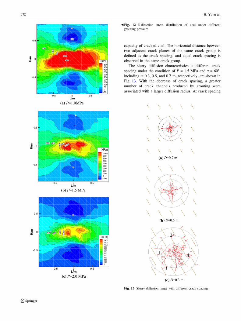
Furthermore, the x-direction stress distribution of coal
under different grouting pressures is displayed in Fig. 12.
A higher grouting pressure increased the internal stress of
coal and resulted in a larger influence range in the coal
body.
4.2 Influence of crack distribution characteristics
on the grouting effect
The geometric characteristics of multi-cracks mainly
include the distribution and arrangement of cracks. The
following section mainly explores the influence of crack
spacing and angle on the slurry diffusion characteristics.
4.2.1 Crack spacing
Crack spacing represent the degree of crack development
in coal, which is an important index for evaluating the flow
1 2 3
-100
-50
0
50
100
150
200
250
Calculation step (103)
Frac
ture
tip
stre
ss (
kPa)
Fracture tip A Fracture tip B Fracture tip C Fracture tip D
Ten
sile
str
ess
Fig. 10 Stress evolution curve at the crack tip
Fig. 11 Slurry diffusion range under different grouting pressure
Macro and micro grouting process and the influence mechanism of cracks in soft coal seam 977
123
capacity of cracked coal. The horizontal distance between
two adjacent crack planes of the same crack group is
defined as the crack spacing, and equal crack spacing is
observed in the same crack group.
The slurry diffusion characteristics at different crack
spacing under the condition of P = 1.5 MPa and a = 60�,including at 0.3, 0.5, and 0.7 m, respectively, are shown in
Fig. 13. With the decrease of crack spacing, a greater
number of crack channels produced by grouting were
associated with a larger diffusion radius. At crack spacing
(a)
(b)
(c)
bFig. 12 X-direction stress distribution of coal under different
grouting pressure
Fig. 13 Slurry diffusion range with different crack spacing
978 H. Yu et al.
123

D = 0.7 m, the fractures produced by the slurry could not
connect with the primary cracks, and the primary cracks
had no obvious influence on the grouting radius, which is
equivalent to Case I. At D = 0.5 m, the grout diffusion
radius had already spread to the primary crack, and the
generated fracture was connected with the primary crack.
The grout flowed along the primary crack and continued to
diffuse outward, while the grouting radius increased to
0.75 m. Furthermore, at crack spacing D = 0.3 m, the
splitting fractures produced by grouting were further
increased, and the intersection occurred between the pri-
mary cracks, as shown in Fig. 13c, which further extended
the grouting channel. Therefore, when the crack spacing is
small, the fractures produced by the slurry will connect the
primary cracks of the coal body and further increase the
diffusion radius by grouting.
4.2.2 Crack angle
The slurry diffusion characteristics of different crack angle
under the condition of P = 1.5 MPa and D = 0.5 m,
including a = 0�, 30�, and 60�, respectively, are shown in
Fig. 14.As it can be seen from Fig. 14, under the same
grouting pressure, the crack angle had little effect on the
grouting radius; however, it had a great influence on the
crack propagation path and direction. As shown in
Fig. 14a, for the primary crack a, the slurry continued to
flow forward after flowing through the primary crack when
a = 0�, resulting in fracture 1, which expanded in the same
direction as that of the fracture a. The nearest position
between primary crack b and the grouting hole was in the
middle of crack b. Some slurry was able to penetrate the
fracture near the middle of crack b and to extend along the
direction perpendicular to the primary crack, resulting in
fracture 2. The remaining part of the slurry flowed along
crack b and split at the tip to form fracture 3.
As shown in Fig. 14b, c, the slurry flowed along the
primary crack and split at the tip. However, the splitting
fracture did not follow the direction of the primary crack,
and was at an angle with the primary crack, which was
related to the maximum principal stress at the tip. Since the
secondary fracture formed by splitting was a tensile frac-
ture, it was more likely to propagate along the direction
parallel to the maximum principal stress.
5 Grouting project of soft coal seam
The roadway 12209 is located in the No. 21 coal seam. It is
supported by a full bolt-mesh and constructed along the
roof of the coal seam. The original cross-section of road-
way is 16 m2, and the total cross-section of the enlarged
roadway is 27.9 m2. In order to prevent the roadway from
being damaged by dynamic pressure during mining,
grouting reinforcement is applied to the entire section of
the enlarged roadway.
Grouting holes were created by an anchor rope drill. The
slurry was mixed with a vertical mixer, and the ZBY-80/
7.0 two-liquid grouting pump was used for grouting.
Considering the performance of the grouting equipment
and according to the field construction experience, the
simulation values of grouting pressure were 1.0, 1.5, and
2.0 MPa, respectively. The change curve of the slurry
diffusion radius with grouting time under different grouting
pressures is shown in Fig. 15. As seen in the figure, with
the increase in grouting time, the growth rate of the slurry
diffusion radius gradually decreased, while the effect of
Fig. 14 Slurry diffusion range with different crack angle
Macro and micro grouting process and the influence mechanism of cracks in soft coal seam 979
123

high grouting pressure on the increase of slurry diffusion
radius was limited; therefore, the final grouting hole pres-
sure was set to 1.5 MPa.
According to the simulation results, the diffusion radius
can reach 0.63 m when the grouting pressure is 1.5 MPa in
the case of coal without primary cracks. Since there are
many cracks in the coal seam of this roadway, the actual
diffusion radius is larger. Therefore, in order to ensure the
grouting effect, as well as take into account the technical
and economic factors, the grouting hole row spacing was
set to 1.6 m, and each row had the same hole depth. A total
of eleven grouting holes were arranged in each row, with
four holes at the top, one at each of the two sides, and five
at the bottom, as shown in Fig. 16. The grouting sequence
involved grouting from bottom to top. Single liquid cement
slurry was used as the grouting material, and 52.5R ordi-
nary Portland cement was mixed with water at a ratio of
1:0.75.
After full-section grouting, the soft coal was reinforced.
Under a grouting pressure of 1.5 MPa, the slurry diffused
well, and the maximum diffusive radius reached approxi-
mately 0.8 m. This shows that it is feasible to determine the
diffusive radius of soft coal under a certain grouting
pressure by simulation, while the reasonable row distance
of grouting holes can also be obtained accordingly. After
grouting, the deformation of the roadway was significantly
reduced, and the stability of the roadway in the soft coal
seam was effectively improved.
6 Conclusions
(1) In the present study, it was reported that the grouting
process of the soft coal seam involved the stages of
seepage, rapid splitting, slow splitting, and then
stability. The existence of primary cracks in the coal
body had an important influence on the grouting
effect of internal stress and fracture propagation
during the grouting process. Secondary fractures
produced by splitting penetrated the primary cracks
of the coal seam. The slurry flowed along the pri-
mary cracks and continued to split the coal seam at
the other tip of the cracks. The existence of primary
cracks significantly increased the grouting diffusion
radius, while it also increased the stress level of the
coal body, resulting in more adequate grouting.
(2) During grouting, the fracture propagation was
mainly caused by the tensile stress at the crack tip.
Due to the effect of the slurry pressure, tensile stress
concentration was formed at the crack tip, leading to
coal seam splitting by the grouting fluid. The slurry
pressure gradually decreased from the grouting hole
to the grouting hole, and thus the tensile stress at the
tip was also gradually decreased. Finally, the grout
diffusion tended to be stable.
(3) The characteristics of the crack distribution had a
great influence on the grouting effect. It was
observed that smaller fracture spacing was
20 40 60 80 10020
30
40
50
60
70
80D
iffu
sion
rad
ius
(cm
)
Grouting time (s)
1.0MPa 1.5MPa 2.0MPa
Fig. 15 Variation curve of slurry diffusion radius under different
grouting pressures
Grouting pipe
8900
7500
2500 2500 2500
2000 2450 20002450
Unit: mm
(a) Full section of the roadway
(b) Grouting hole of the floor 20
0024
50
1600 1600 1600
Grouting hole
Row space
1600
Fig. 16 Layout of grouting holes in roadway 12209
980 H. Yu et al.
123

associated with a larger slurry diffusion radius and
thus easier penetration of the primary crack tips. The
crack angle affected the direction of fracture prop-
agation. Furthermore, the secondary fracture formed
by splitting was a tensile fracture. When the grouting
pressure was small, the grouting radius increased
along with the increase in pressure. However, when
the grouting pressure reached a certain value,
increasing the grouting pressure had little effect on
the grouting radius.
7 Discussion
The results of the present study suggest that, according to
the discrete element simulation, the grout diffusion range
under a certain grouting pressure can be obtained, which
has great guiding significance for setting a reasonable
grouting hole spacing in grouting engineering practice. Due
to the irregular crack distribution in the real coal body,
there is inevitable deviation between the actual diffusion
radius of the slurry and the simulation value. Therefore,
attention should be paid to the actual crack development of
the coal body during the grouting construction.
Acknowledgments The authors acknowledge the financial support
provided by the National Natural Science Foundation of China (No.
51604094 and 51674098), and the Shandong Provincial Natural
Science Foundation (No.ZR2020QE118).
Data availability The data used to support the findings of this study
are available from the corresponding author upon request.
Compliance with ethical standards
Conflict of interest The authors declare that they have no conflicts of
interest.
Open Access This article is licensed under a Creative Commons
Attribution 4.0 International License, which permits use, sharing,
adaptation, distribution and reproduction in any medium or format, as
long as you give appropriate credit to the original author(s) and the
source, provide a link to the Creative Commons licence, and indicate
if changes were made. The images or other third party material in this
article are included in the article’s Creative Commons licence, unless
indicated otherwise in a credit line to the material. If material is not
included in the article’s Creative Commons licence and your intended
use is not permitted by statutory regulation or exceeds the permitted
use, you will need to obtain permission directly from the copyright
holder. To view a copy of this licence, visit http://creativecommons.
org/licenses/by/4.0/.
References
Ajamzadeh M, Sarfarazi V, Dehghani H (2019) Evaluation of plow
system performance in long-wall mining method using particle
flow code. Int J Coal Sci Technol 6(4):518–535
Bandyopadhyay K, Mallik J, Ghosh T (2020) Dependence of fluid
flow on cleat aperture distribution and aperture–length scaling: a
case study from Gondwana coal seams of Raniganj Formation,
Eastern India. Int J Coal Sci Technol 7(1):133–146
Bezuijen A, Grotenhuis R, Tol AF (2011) Analytical model for
fracture grouting in sand. J Geotech geoenviron Eng
137(6):611–620
Boschi K, Prisco CG, Ciantia MO (2020) Micromechanical investi-
gation of grouting in soils. Int J Solids Struct 187:121–132
Chen TL, Zhang LY, Zhang DL (2014) An FEM/VOF hybrid
formulation for fracture grouting modelling. Comput Geotech
58:14–27
Cheng WC, Ni JC, Shen JS (2018) Modeling of permeation and
fracturing grouting in sand: laboratory investigations. J Test Eval
46(5):2067–2082
Christoffersen J, Mehrabadi MM, Nemat-Nasser S (1981) A
micromechanical description of granular material behavior.
J Appl Mech 48:339–344
Damjanac B, Cundall P (2016) Application of distinct element
methods to simulation of hydraulic fracturing in naturally
fractured reservoirs. Comput Geotech 71(1):283–294
Deng SH, Wang XL, Yu J (2018) Simulation of grouting process in
rock masses under a dam foundation characterized by a 3d
fracture network. Rock Mech Rock Eng 51:1801–1822
Geng P, Lu ZK, Ding T (2012) Study on dynamic process simulation
of surrounding rock grouting based on particle flow. J Rock
Mech Eng 31:445–452
Gothall R, Stille H (2009) Fracture-fracture interaction during
grouting. Tunn Undergr Sp Technol 25:199–204
Hu JH, Ren QF, Ma SW et al (2019) Macroscopic and microscopic
trans-scale characteristics of pore structure of mine grouting
materials. T Nonferr Metal Soc 29:1067–1081
Jiang DH, Cheng XZ, Luan HJ (2018) Experimental investigation on
the law of grout diffusion in fractured porous rock mass and its
application. Processes 6(10):191
Jiang LS, Kong P, Shu JM et al (2019) Numerical Analysis of Support
Designs Based on a Case Study of a Longwall Entry. Rock Mech
Rock Eng 52(9):3373–3384
Jiang LS, Kong P, Zhang PP et al (2020) Dynamic Analysis of the
Rock Burst Potential of a Longwall Panel Intersecting with a
Fault. Rock Mech Rock Eng 53(4):1737–1754
Jin LC, Sui WH, Xiong JL (2019) Experimental investigation on
chemical grouting in a permeated fracture replica with different
roughness. Appl Sci 9(13):2762
Koyama T, Katayama T, Tanaka T et al (2013) Development of a
numerical model for grout injection and its application to the
in situ grouting test at the Grimsel test site. Switzerland Geosyst
Eng 16(1):26–36
Kvartsberg S, Fransson A (2013) Hydrogeological characterisation
and stochastic modelling of a hydraulically conductive fracture
system affected by grouting: A case study of horizontal circular
drifts. Tunn Undergr Sp Technol 38(9):38–49
Lei QH, Latham JP, Tsang CF (2016) The use of discrete fracture
networks for modelling coupled geomechanical and hydrological
behaviour of fractured rocks. Comput Geotech 85:151–176
Liu QS, Sun L (2019) Simulation of coupled hydro-mechanical
interactions during grouting process in fractured media based on
the combined finite-discrete element method. Tunn Undergr Sp
Technol 84(2):472–486
Liu SW, Fu MX, Jia HS et al (2018) Shear Characteristics of
Cuneiform Reaming Anchorage Bolts in Coal Mine Roadways.
Rock Mech Rock Eng 52(6):1931–1943
Liu XL, Wang F, Huang J et al (2019) Grout diffusion in silty fine
sand stratum with high groundwater level for tunnel construc-
tion. Tunn Undergr Sp Technol 93(11):103051.1–103051.11
Macro and micro grouting process and the influence mechanism of cracks in soft coal seam 981
123

Lombardi G, Deere D (1993) Grouting design and control using the
GIN principle. Int Water Power Dam Constr 45(6):15–22
Rafi JY, Stille H (2014) Control of rock jacking considering spread of
grout and grouting pressure. Tunn Undergr Sp Technol
40(2):1–15
Sha F, Lin CJ, Li ZF (2019) Reinforcement simulation of water-rich
and broken rock with Portland cement-based grout. Constr Build
Mater 221:292–300
Stille H, Gustafson G, Hassler L (2012) Application of new theories
and technology for grouting of dams and foundations on rock.
Geotech Geol Eng 30(3):603–624
Sun F, Zhang DL, Chen TL (2010) Study on meso-mechanical
simulation of fracture grouting in soil. Chin J Geotech Eng
32(3):474–480
Wang XC, Liu RT, Yang WM (2019) Study on diffusion mechanism
of horizontal fracture grouting considering water evolution of
cement slurry. J Rock Mech Eng 35(5):1005–1017
Wang X, Yuan W, Yan YT (2020) Scale effect of mechanical
properties of jointed rock mass: a numerical study based on
particle flow code. Geomech Eng 21(3):259–268
Xiao F, Shang JL, Zhao ZY (2019) DDA based grouting prediction
and linkage between fracture aperture distribution and grouting
characteristics. Comput Geotech 112:350–369
Xiao F, Zhao ZY, Chen HM (2017) A simplified model for predicting
grout flow in fracture channels. Tunn Undergr Sp Technol
70:11–18
Xu ZP, Liu CW, Zhou XW et al (2019) Full-scale physical modelling
of fissure grouting in deep underground rocks. Tunn Undergr Sp
Technol 89(7):249–261
Zhang DM, Gao P, Yin ZY (2017) Particle flow simulation of tunnel
seepage erosion. Geotech Mech 38:429–438
Zhang ZY, Hideki S (2018) Numerical study on the effectiveness of
grouting reinforcement on the large heaving floor of the deep
retained goaf-side gateroad: a case study in china. Energies
11(4):1001–1015
Zhang ZL, Shao ZS, Fang XB et al (2018) Research on the fracture
grouting mechanism and pfc numerical simulation in loess. Adv
Mater Sci Eng 2018:1–7
Zhang DL, Sun F, Li PF (2012) Research and application of
composite grouting mechanism for submarine tunnel. J Rock
Mech Eng 31:445–452
Zuo JP, Wang JT, Jiang YQ (2019) Macro/meso failure behavior of
surrounding rock in deep roadway and its control technology. Int
J Coal Sci Technol 6(3):301–319
982 H. Yu et al.
123