macintosh performa 6100 series - tim.id.autim.id.au › laptops › apple › legacy ›...
TRANSCRIPT

Service Source
K
Macintosh Performa 6100 Series
Macintosh Performa 6110CD, 6112CD, 6115CD,6116CD, 6117CD, 6118CD
Service Source
K
Basics
Macintosh Performa 6100 Series
Basics Power Macintosh System Overview - 1
Power Macintosh System Overview
PowerPC microprocessors are a family of processors built on reduced instruction-set computing (RISC) technology. RISC processors streamline the internal workings of computers. Whereas traditional (complex instruction-set computing, or CISC) processors contain a wide variety of instructions to handle many different tasks, RISC processors contain only those instructions that are used most often. When a complex instruction is needed, a RISC processor builds it from a combination of basic instructions.
RISC processors are designed to execute these basic instructions extremely quickly. The performance gains achieved by speeding up the most-used instructions more than compensate for the time spent creating less-used instructions.

Basics Power Macintosh System Overview - 2
Previously, RISC technology had been used only in high-end workstations and commercial database servers. With the introduction of Macintosh PowerPC computers, Apple succeeded in bringing RISC technology to personal computing.
Key Points
Three key points to remember about a PowerPC processor-based Macintosh system: It's a Macintosh; it's compatible; it offers tremendous performance.
Apple's PowerPC computers feature the same user interface as their 680x0-based predecessors. Users can mix RISC-based and 680x0-based Macintosh systems on the same net-work and exchange files and disks between them. In addition, users can run both 680x0 and native PowerPC applications on the same Power Macintosh system simultaneously.
Basics Power Macintosh System Overview - 3
Compatibility is not limited just to applications. INITs, CDEVs, drivers, and other Macintosh utility software also work on PowerPC processor-based Macintosh systems. So do AppleTalk devices (such as printers), SCSI devices (such as hard drives and scanners), ADB devices (such as mice, trackballs, and keyboards), and other Macintosh cards and peripherals.
The primary operating system for PowerPC processor-based Macintosh computers is System 7. The operating system has been optimized for the highest performance on the PowerPC processor. This optimization of System 7 benefits applications written for 680x0 systems as well as those developed specifically for PowerPC processor-based systems.
And while PowerPC-based Macintosh systems running native applications offer two to four times the performance
Basics Power Macintosh System Overview - 4
of the fastest 68040- and 80486-based personal computers, the real promise of PowerPC technology is that it enables Apple and other developers to deliver new software capabilities on Macintosh systems that were previously available only on high-end workstations.
Troubleshooting Tips
When troubleshooting Power Macintosh systems, keep in mind the following:
1 If a Power Macintosh system does not power up, you should first attempt to reset the logic board. Instruc-tions are provided in the Additional Procedures chapter.
2 With Power Macintosh computers, you must install noncomposite RAM SIMMs only, and the RAM SIMMs must be installed in like pairs (that is, the same size and speed). Additional troubleshooting information is

Basics Power Macintosh System Overview - 5
provided in the Symptom Charts section of the Troubleshooting chapter under the “System” topic heading.
3 If a Power Macintosh system has bad RAM SIMMs installed, you will not hear death chimes. Instead, a dialog box will appear alerting you to the fact that a bad RAM SIMM has been detected. Additional troubleshooting information is provided in the Symptom Charts section of the Troubleshooting chapter under the “System” topic heading.
4 If the system hangs shortly after installing a new NuBus card, contact the vendor to verify that the card is compatible with the Power Macintosh system or to see if there is a software upgrade available. If the NuBus card is an Apple manufactured product, refer to the Service Tech Info Library for more information.

Basics Product Configurations - 6
Product Configurations
All configurations are at introduction of the product.
Performa 6110CD
• Memory: 8 MB of RAM• Drives: Internal Apple 1.4 MBSuperDrive, internal 250
MB SCSI hard drive, internal AppleCD 300i Plus drive• Modem: Teleport send-fax/data modem • Monitor: Apple Multiple Scan 15 Display
Performa 6112CD
• Memory: 8 MB of RAM• Storage: Internal Apple 1.4 MB SuperDrive, internal
250 MB SCSI hard drive, internal AppleCD 300i Plus drive
• Modem: Teleport send-fax/data modem • Monitor: Apple Multiple Scan 15 Display
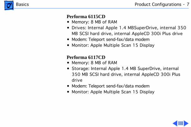
Basics Product Configurations - 7
Performa 6115CD
• Memory: 8 MB of RAM• Drives: Internal Apple 1.4 MBSuperDrive, internal 350
MB SCSI hard drive, internal AppleCD 300i Plus drive• Modem: Teleport send-fax/data modem • Monitor: Apple Multiple Scan 15 Display
Performa 6117CD
• Memory: 8 MB of RAM• Storage: Internal Apple 1.4 MB SuperDrive, internal
350 MB SCSI hard drive, internal AppleCD 300i Plus drive
• Modem: Teleport send-fax/data modem • Monitor: Apple Multiple Scan 15 Display
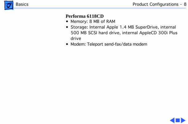
Basics Product Configurations - 8
Performa 6118CD
• Memory: 8 MB of RAM• Storage: Internal Apple 1.4 MB SuperDrive, internal
500 MB SCSI hard drive, internal AppleCD 300i Plus drive
• Modem: Teleport send-fax/data modem
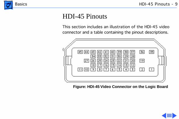
Basics HDI-45 Pinouts - 9
HDI-45 Pinouts
This section includes an illustration of the HDI-45 video connector and a table containing the pinout descriptions.
(Insert HDI 45 pinout table here.)
Figure: HDI-45 Video Connector on the Logic Board
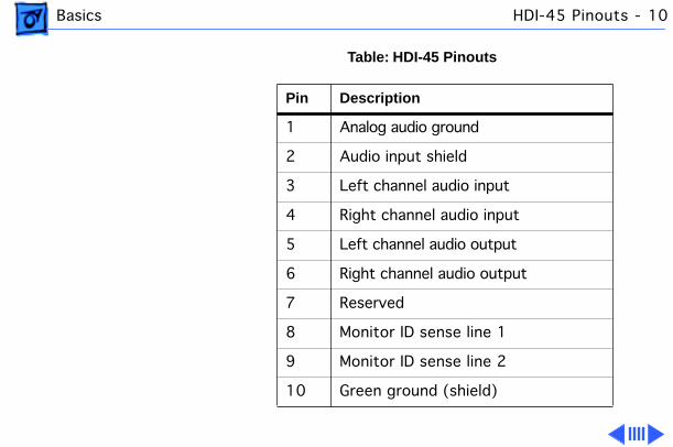
Basics HDI-45 Pinouts - 10
Table: HDI-45 Pinouts
Pin Description
1 Analog audio ground
2 Audio input shield
3 Left channel audio input
4 Right channel audio input
5 Left channel audio output
6 Right channel audio output
7 Reserved
8 Monitor ID sense line 1
9 Monitor ID sense line 2
10 Green ground (shield)
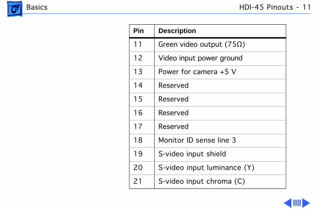
Basics HDI-45 Pinouts - 11
11 Green video output (75Ω)
12 Video input power ground
13 Power for camera +5 V
14 Reserved
15 Reserved
16 Reserved
17 Reserved
18 Monitor ID sense line 3
19 S-video input shield
20 S-video input luminance (Y)
21 S-video input chroma (C)
Pin Description

Basics HDI-45 Pinouts - 12
22 Reserved
23 Reserved
24 Reserved
25 Reserved
26 Red ground (shield)
27 Red video output (75Ω)
28 I
2
C data signal
29 I
2
C clock signal
30 Reserved
31 Monitor ID
32 Monitor ID
Pin Description
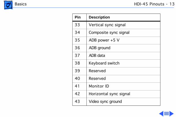
Basics HDI-45 Pinouts - 13
33 Vertical sync signal
34 Composite sync signal
35 ADB power +5 V
36 ADB ground
37 ADB data
38 Keyboard switch
39 Reserved
40 Reserved
41 Monitor ID
42 Horizontal sync signal
43 Video sync ground
Pin Description
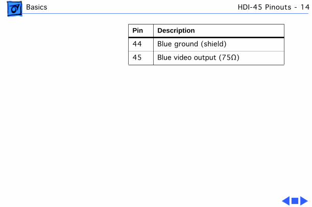
Basics HDI-45 Pinouts - 14
44 Blue ground (shield)
45 Blue video output (75Ω)
Pin Description
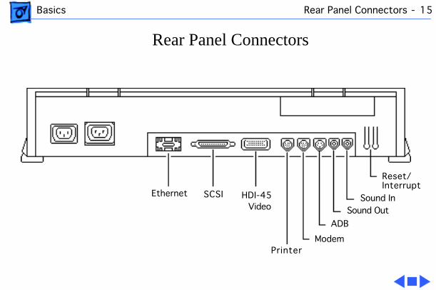
Basics Rear Panel Connectors - 15
Rear Panel Connectors
Ethernet SCSI HDI-45 Video
PrinterModem
ADB
Sound OutSound In
Reset/Interrupt
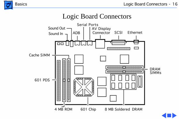
Basics Logic Board Connectors - 16
Logic Board Connectors
601 Chip
Serial Ports
DRAMSIMMs
4 MB ROM
601 PDS
8 MB Soldered DRAM
Cache SIMM
Sound Out
Sound In ADBAV DisplayConnector SCSI Ethernet
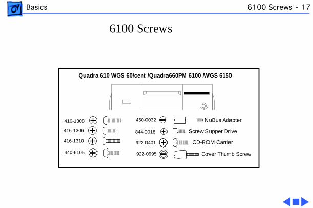
Basics 6100 Screws - 17
6100 Screws
Quadra 610 WGS 60/cent /Quadra660PM 6100 /WGS 6150
844-0018
922-0401
410-1308
416-1310
416-1306
440-6105
450-0032
922-0995 Cover Thumb Screw
Screw Supper Drive
CD-ROM Carrier
NuBus Adapter
Service Source
K
Specifications
Macintosh Performa 6100 Series
Specifications Processor - 1
Processor
CPU
60 MHz PowerPC 601 RISC microprocessor Built-in MMU and FPU32K of on-chip cache memoryRequires system software version 7.5 or later
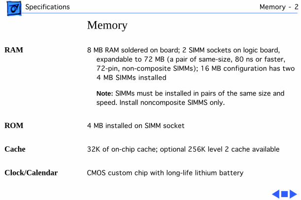
Specifications Memory - 2
Memory
RAM
8 MB RAM soldered on board; 2 SIMM sockets on logic board, expandable to 72 MB (a pair of same-size, 80 ns or faster, 72-pin, non-composite SIMMs); 16 MB configuration has two 4 MB SIMMs installed
Note:
SIMMs must be installed in pairs of the same size and speed. Install noncomposite SIMMS only.
ROM
4 MB installed on SIMM socket
Cache
32K of on-chip cache; optional 256K level 2 cache available
Clock/Calendar
CMOS custom chip with long-life lithium battery

Specifications Disk Storage - 3
Disk Storage
Floppy Drive
1.4 MB Apple SuperDrive Manual Insert
Hard Drive
Performa 6110 and Performa 6112: 250 MB hard drivePerforma 6115 and Performa 6117: 350 MB hard drivePerforma 6118: 500 MB hard drive
CD-ROM
Internal AppleCD 300i Plus CD-ROM drive

Specifications I/O Interfaces - 4
I/O Interfaces
SCSI
One SCSI port; DB-25 connector Supports a maximum of six external SCSI devices (five when CD-
ROM is installed)
Serial
Two RS-232/RS-422 LocalTalk/GeoPort serial ports; mini DIN-9 connectors (backward compatible with mini DIN-8 connectors)
Apple Desktop Bus
One Apple Desktop Bus (ADB) port; mini DIN-4 connectorMaximum power draw 500 mA; maximum of three devices total
Expansion Slot
Internal expansion slot supports either a processor-direct slot card or 7-in. NuBus card (with appropriate adapter)
Specifications I/O Interfaces - 5
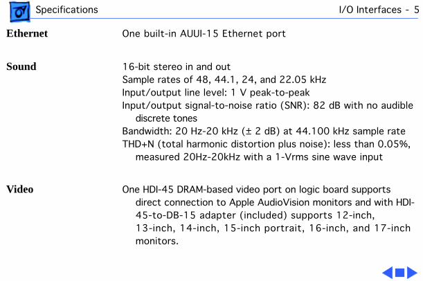
Ethernet
One built-in AUUI-15 Ethernet port
Sound
16-bit stereo in and outSample rates of 48, 44.1, 24, and 22.05 kHzInput/output line level: 1 V peak-to-peakInput/output signal-to-noise ratio (SNR): 82 dB with no audible
discrete tonesBandwidth: 20 Hz-20 kHz (± 2 dB) at 44.100 kHz sample rate THD+N (total harmonic distortion plus noise): less than 0.05%,
measured 20Hz-20kHz with a 1-Vrms sine wave input
Video
One HDI-45 DRAM-based video port on logic board supports direct connection to Apple AudioVision monitors and with HDI-45-to-DB-15 adapter (included) supports 12-inch, 13-inch, 14-inch, 15-inch portrait, 16-inch, and 17-inch monitors.

Specifications I/O Devices - 6
I/O Devices
Keyboard
Apple Design Keyboard
Mouse
ADB Mouse II; draws up to 10 mA

Specifications Video Display - 7
Video Display
Video Display
Performa 6100 Series computers are bundled with the Apple Multiple Scan 15 display. Performa 6100 Series computers support monochrome, color, VGA, and SVGA formats on the HDI-45 connector, including:
• Macintosh 12-inch Monochrome Display (640 x 480)• Macintosh 12-inch RGB Display (512 x 384)• AppleColor High-Resolution RGB 14” Monitor (640 x 480)• Apple AudioVision 14 Display (640 x 480)• Macintosh Color Display (640 x 480) • Macintosh 15-inch Portrait Display (640 x 870) • Macintosh 16-inch Color Display (832 x 624)
Specifications Electrical - 8
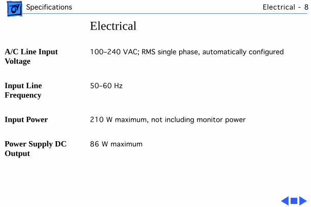
Electrical
A/C Line Input Voltage
100–240 VAC; RMS single phase, automatically configured
Input Line Frequency
50–60 Hz
Input Power
210 W maximum, not including monitor power
Power Supply DC Output
86 W maximum
Specifications Physical - 9
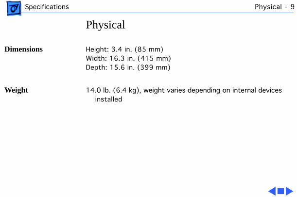
Physical
Dimensions
Height: 3.4 in. (85 mm)Width: 16.3 in. (415 mm)Depth: 15.6 in. (399 mm)
Weight
14.0 lb. (6.4 kg), weight varies depending on internal devices installed

Specifications Environmental - 10
Environmental
Operating Temperature
10–40° C (50–104° F)
Storage Temperature
-40 to 47° C (-40 F to 116.6° F)
Relative Humidity
5–95% (noncondensing)
Altitude
0–3,048 m (0–10,000 ft.)

Service Source
K
Troubleshooting
Macintosh Performa 6100 Series

Troubleshooting General/ - 1
General
The Symptom Charts included in this chapter will help you diagnose specific symptoms related to your product. Because cures are listed on the charts in the order of most likely solution, try the first cure first. Verify whether or not the product continues to exhibit the symptom. If the symptom persists, try the next cure. (Note: If you have replaced a module, reinstall the original module before you proceed to the next cure.)
If you are not sure what the problem is, or if the Symptom Charts do not resolve the problem, refer to the Flowchart for the product family in the Troubleshooting tab.
For additional assistance, contact Apple Technical Support.
Troubleshooting Symptom Charts/Power Supply - 2
Symptom Charts
Power Supply
System does not power up
1 Reset logic board. (Refer to Additional Procedures.)2 Reseat ROM SIMM and cache SIMM.3 Replace power supply.4 Replace logic board.
Troubleshooting Symptom Charts/System - 3
System
System intermittently crashes or hangs
1 Verify that system software is version 7.5 or later.2 Verify SIMMs are noncomposite and installed in like pairs
(same size/speed).3 Verify that software is known-good.4 Verify that software is PowerPC compatible (contact
developer).5 Clear parameter RAM. Hold down <Command> <Option> <P>
<R> during startup but before “Welcome to Macintosh” appears.
6 Replace SIMMs.7 Replace logic board. Retain SIMMs.8 Replace power supply.
Troubleshooting Symptom Charts/Video - 4
Video
Screen is dark, audio and at least one drive operate, fan is running, and LED is l it
1 Adjust brightness on monitor.2 Replace video cable.3 Replace monitor. Refer to appropriate monitor manual to
troubleshoot defective monitor.4 Replace logic board. Retain customer’s SIMMs.
Screen is dark, audio and drive do not operate, fan is running, and LED is l it
1 Reset logic board. (Refer to Additional Procedures.)2 Reseat ROM SIMM and cache SIMM.3 Remove peripherals.4 Replace DRAM SIMMs.5 Replace power supply.6 Replace logic board.

Troubleshooting Symptom Charts/Video
(Continued)
- 5
Video
(Continued)
Partial or whole screen is bright and audio is present, but no video information is visible
1 Replace video cable.2 Replace monitor. Refer to appropriate monitor manual to
troubleshoot defective monitor. 3 Replace logic board. Retain customer’s SIMMs.
Screen is completely dark, fan is not running, and LED is not lit
1 Verify that external power cables are properly connected.2 Remove peripherals.3 Replace power supply.4 Replace logic board. Retain customer’s SIMMs.

Troubleshooting Symptom Charts/Floppy Drive - 6
Floppy Drive
Audio and video are present, but internal floppy drive does not operate
1 Replace internal floppy drive cable.2 Replace internal floppy drive.3 Replace logic board. Retain customer’s SIMMs.
Floppy disk ejects, and display shows Mac icon with blinking “X”
1 Try a different floppy disk.2 Replace floppy drive cable.3 Replace internal floppy drive.4 Replace logic board. Retain customer’s SIMMs.
Floppy disk does not eject
1 Switch off system and hold mouse button down while switching on the system.
2 Eject disk manually.3 Replace floppy drive cable.4 Replace floppy drive.
Troubleshooting Symptom Charts/Floppy Drive
(Continued)
- 7
Floppy Drive
(Continued)
Floppy drive attempts to eject disk but doesn’t
1 Push floppy disk completely in.2 Eject floppy disk manually.3 Replace floppy drive.4 Reseat or replace top cover assembly.

Troubleshooting Symptom Charts/Hard Drive - 8
Hard Drive
Internal hard drive runs continuously
1 Update driver software of hard drive, using HD-SC Setup.2 Reinstall system software.3 Replace SCSI data cable.4 Replace hard drive.5 Replace logic board. Retain customer’s SIMMs.
Internal hard drive does not operate
1 Replace SCSI data cable.2 Replace SCSI power cable.3 Replace hard drive.4 Replace logic board. Retain customer’s SIMMs.
Troubleshooting Symptom Charts/CD-ROM Drive - 9
CD-ROM Drive
CD-ROM drive does not accept a compact disc
1 Exchange disc (if disc is dirty or damaged).2 Replace CD-ROM drive mechanism.3 Replace SCSI data cable.
System does not display CD-ROM drive icon
1 Verify that CD-ROM extension is in System Folder. 2 Replace CD-ROM drive mechanism.3 Replace SCSI data cable.
Compact disc won’t eject from the drive
1 Turn off file sharing in Sharing Setup Control Panel.2 Manually eject the compact disc.3 Press the eject button behind the front bezel (if it is
accessible).4 Replace CD-ROM drive mechanism.

Troubleshooting Symptom Charts/Peripherals - 10
Peripherals
Works with internal or external SCSI device, but does not work with both
1 Replace external SCSI cables.2 Verify that there is only one terminator on external devices.3 Verify that SCSI select switch on any external device is set
differently from any internal SCSI device.4 Verify that hard drive is terminated but optional CD-ROM is
not terminated. 5 Replace terminator on external hard drive. 6 Replace SCSI select cable on external SCSI device.

Troubleshooting Symptom Charts/Peripherals
(Continued)
- 11
Peripherals
(Continued)
Cursor does not move 1 Reboot computer.2 Verify that mouse is connected properly.3 If mouse was connected to keyboard, connect mouse to
computer ADB port instead. If mouse works, replace keyboard.
4 If mouse does not work in any ADB port on computer, replace mouse.
5 Replace logic board. Retain customer’s SIMMs.
Cursor moves, but clicking the mouse button has no effect
1 Replace mouse.2 Replace logic board. Retain customer’s SIMMs.3 If mouse was connected to keyboard, connect mouse to
computer ADB port instead. If mouse works, replace keyboard.

Troubleshooting Symptom Charts/Peripherals
(Continued)
- 12
Peripherals
(Continued)
Double-click does not open application, disk, or server
1 Remove duplicate system files from hard drive.2 Clear parameter RAM. Hold down <Command> <Option> <P>
<R> during startup but before “Welcome to Macintosh” appears.
3 If mouse was connected to keyboard, connect mouse to computer ADB port instead. If mouse works, replace keyboard.
4 If mouse does not work in any ADB port on computer, replace mouse.
5 Replace logic board. Retain customer’s SIMMs.
No response to any key on the keyboard
1 Verify that keyboard is connected to ADB port.2 Replace keyboard cable.3 Replace keyboard.4 Replace logic board. Retain customer’s SIMMs.
Troubleshooting Symptom Charts/Miscellaneous - 13
Miscellaneous
About This Macintosh reports more memory than is installed
1 Verify that RAM SIMMs are installed in matching pairs (same size and speed).
2 Replace RAM SIMMs.
About This Macintosh reports less memory than is installed
1 Verify that RAM SIMMs are installed in matching pairs (same size and speed).
2 Replace RAM SIMMs.
Service Source
K
Take Apart
Macintosh Performa 6100 Series

Take Apart Top Cover - 1
Top Cover
No preliminary steps are required before you begin this procedure.Top Cover
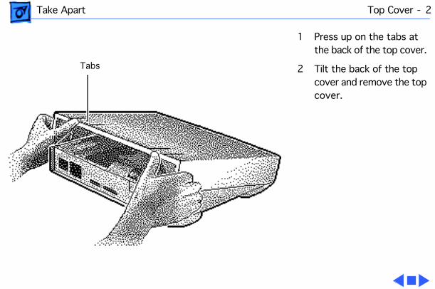
Take Apart Top Cover - 2
1 Press up on the tabs at the back of the top cover.
2 Tilt the back of the top cover and remove the top cover.
Tabs
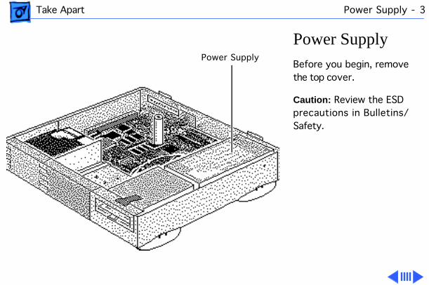
Take Apart Power Supply - 3
Power Supply
Before you begin, remove the top cover.
Caution:
Review the ESD precautions in Bulletins/Safety.
Power Supply
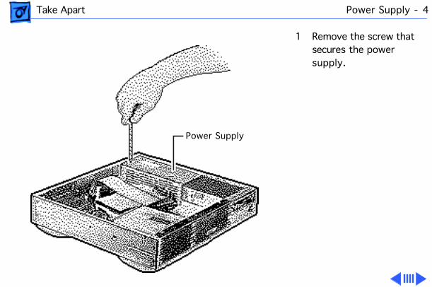
Take Apart Power Supply - 4
1 Remove the screw that secures the power supply.
Power Supply
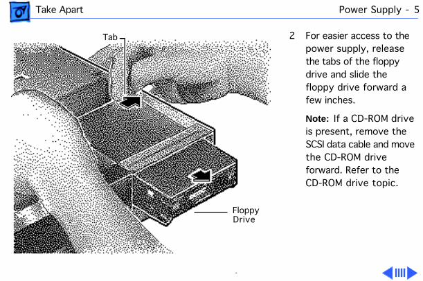
Take Apart Power Supply - 5
2 For easier access to the power supply, release the tabs of the floppy drive and slide the floppy drive forward a few inches.
Note:
If a CD-ROM drive is present, remove the SCSI data cable and move the CD-ROM drive forward. Refer to the CD-ROM drive topic.
Tab
Floppy Drive
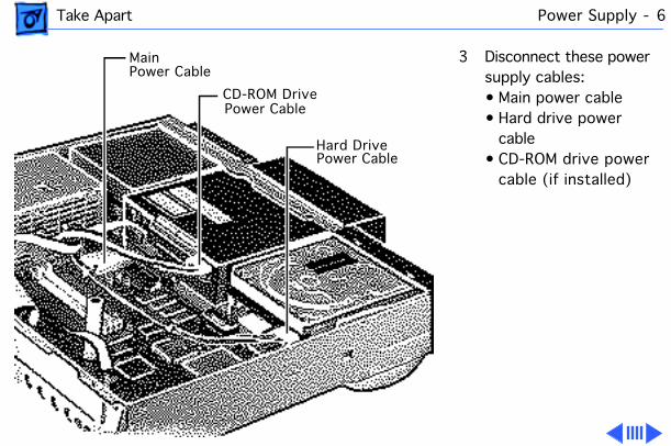
Take Apart Power Supply - 6
3 Disconnect these power supply cables: • Main power cable• Hard drive power
cable• CD-ROM drive power
cable (if installed)
Main Power Cable
CD-ROM Drive
Hard Drive
Power Cable
Power Cable
Take Apart Power Supply - 7
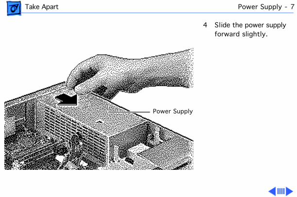
4 Slide the power supply forward slightly.
Power Supply
Take Apart Power Supply - 8
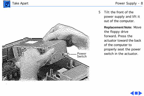
5 Tilt the front of the power supply and lift it out of the computer.
Replacement Note:
Move the floppy drive forward. Press the actuator toward the back of the computer to properly seat the power switch in the actuator.Power
Switch

Take Apart Logic Board - 9
Logic Board
Before you begin, remove the following:• Top cover• Power supply (optional)• Power Macintosh AV
card, if installed (Refer to Expansion Cards in Additional Procedures.)
Caution:
Review the ESD precautions in Bulletins/Safety.
Logic Board
Take Apart Logic Board - 10
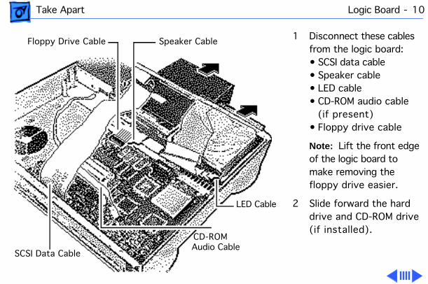
1 Disconnect these cables from the logic board:• SCSI data cable• Speaker cable• LED cable• CD-ROM audio cable
(if present)• Floppy drive cable
Note:
Lift the front edge of the logic board to make removing the floppy drive easier.
2 Slide forward the hard drive and CD-ROM drive (if installed).
Ê
Speaker Cable
LED Cable
CD-ROM
SCSI Data Cable
Floppy Drive Cable
Audio Cable

Take Apart Logic Board - 11
3
Note:
The logic board is secured with two screws.
Using a long Phillips screwdriver, remove the screw from the center of the standoff. Remove the standoff.
4 Remove the Phillips screw from the front edge of the logic board.
5 Remove customer’s RAM SIMMs and 256K cache SIMM.
Note:
Do
not
remove the ROM SIMM.
Standoff withInternal Screw
Take Apart Logic Board - 12
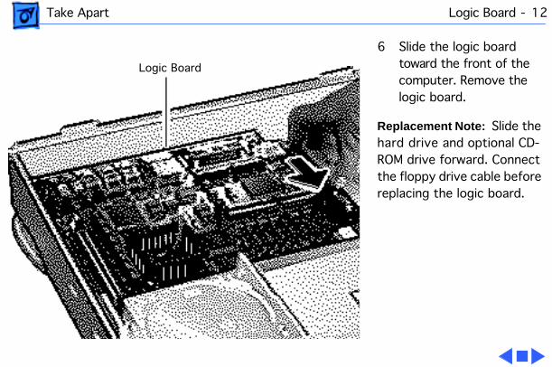
6 Slide the logic board toward the front of the computer. Remove the logic board.
Replacement Note:
Slide the hard drive and optional CD-ROM drive forward. Connect the floppy drive cable before replacing the logic board.
Logic Board
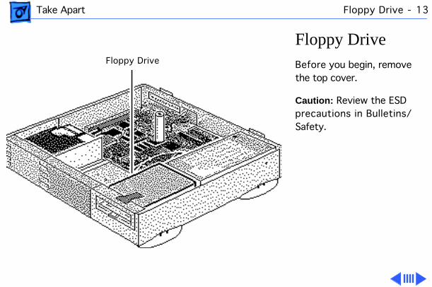
Take Apart Floppy Drive - 13
Floppy Drive
Before you begin, remove the top cover.
Caution:
Review the ESD precautions in Bulletins/Safety.
Floppy Drive
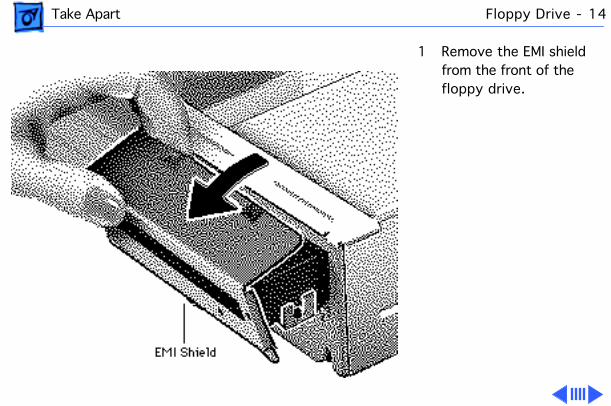
Take Apart Floppy Drive - 14
1 Remove the EMI shield from the front of the floppy drive.
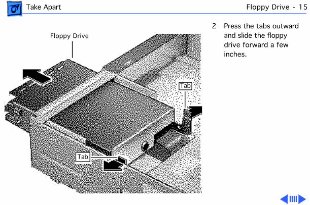
Take Apart Floppy Drive - 15
2 Press the tabs outward and slide the floppy drive forward a few inches.
Floppy Drive
Tab
Tab

Take Apart Floppy Drive - 16
3 Disconnect the floppy drive cable.
Note:
You can easily reach the floppy drive cable connector when the floppy drive is forward.
4 Slide out the floppy drive.
Floppy Drive Cable

Take Apart Hard Drive - 17
Hard Drive
Before you begin, remove the top cover.
Caution:
Review the ESD precautions in Bulletins/Safety.
Hard Drive

Take Apart Hard Drive - 18
1 Disconnect the SCSI data and hard drive power cables from the hard drive.
SCSI Data Cable
Hard Drive Power Cable

Take Apart Hard Drive - 19
2 Remove the hard drive EMI shield.
Hard Drive EMI Shield
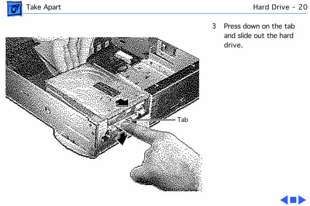
Take Apart Hard Drive - 20
3 Press down on the tab and slide out the hard drive.
Tab

Take Apart CD-ROM Drive - 21
CD-ROM Drive
Before you begin, remove the top cover.
Caution:
Review the ESD precautions in Bulletins/Safety.
CD-ROM Drive

Take Apart CD-ROM Drive - 22
1 Disconnect the SCSI data cable and CD-ROM drive power cable from the CD-ROM drive.
2 Disconnect the CD-ROM audio cable.
CD-ROMPower
Cable
SCSI Data Cable

Take Apart CD-ROM Drive - 23
3 Remove the CD-ROM drive EMI shield.
Bottom Cover
CD-ROM EMI Shield

Take Apart CD-ROM Drive - 24
4 Press up on the tab and slide out the CD-ROM drive.
Replacement Note:
Be sure to remove the CD-ROM drive from the carrier prior to returning the drive to Apple.
Tab
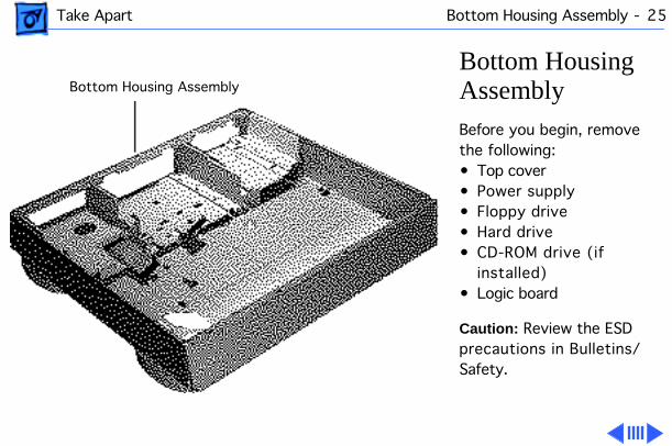
Take Apart Bottom Housing Assembly - 25
Bottom Housing Assembly
Before you begin, remove the following:• Top cover• Power supply• Floppy drive• Hard drive• CD-ROM drive (if
installed)• Logic board
Caution:
Review the ESD precautions in Bulletins/Safety.
Bottom Housing Assembly
Take Apart Bottom Housing Assembly - 26
Note:
Once you have removed all the parts listed above, the bottom housing assembly is what remains. It includes the floppy drive cable, LED cable, speaker, and internal chassis.
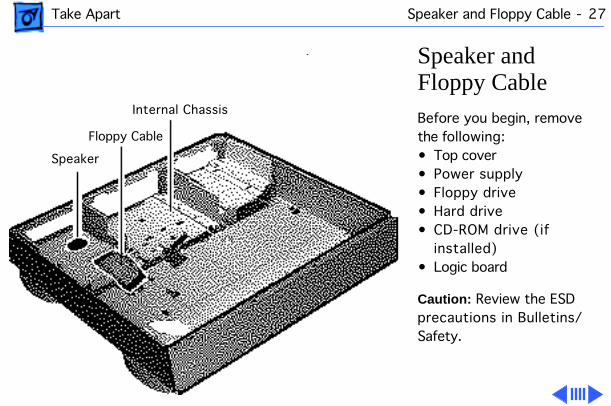
Take Apart Speaker and Floppy Cable - 27
Speaker and Floppy Cable
Before you begin, remove the following:• Top cover• Power supply• Floppy drive• Hard drive• CD-ROM drive (if
installed)• Logic board
Caution:
Review the ESD precautions in Bulletins/Safety.
Ê
Internal Chassis
Floppy Cable
Speaker
Take Apart Speaker and Floppy Cable - 28
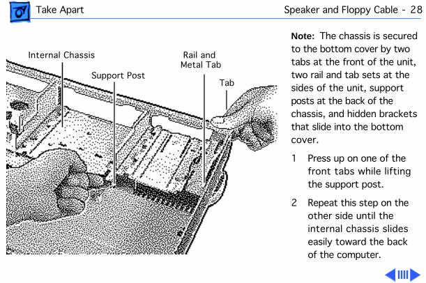
Note:
The chassis is secured to the bottom cover by two tabs at the front of the unit, two rail and tab sets at the sides of the unit, support posts at the back of the chassis, and hidden brackets that slide into the bottom cover.
1 Press up on one of the front tabs while lifting the support post.
2 Repeat this step on the other side until the internal chassis slides easily toward the back of the computer.
Internal Chassis
Support Post
Rail and
Tab
Metal Tab

Take Apart Speaker and Floppy Cable - 29
3 Press down and slide the chassis toward the back of the computer.
4 Remove the chassis.
Internal Chassis
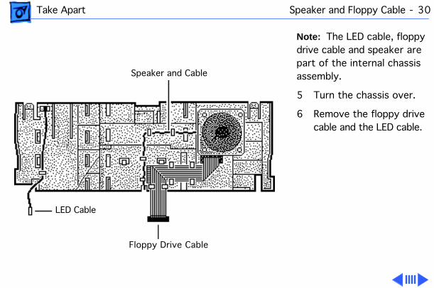
Take Apart Speaker and Floppy Cable - 30
Note:
The LED cable, floppy drive cable and speaker are part of the internal chassis assembly.
5 Turn the chassis over.
6 Remove the floppy drive cable and the LED cable.
Speaker and Cable
Floppy Drive Cable
LED Cable
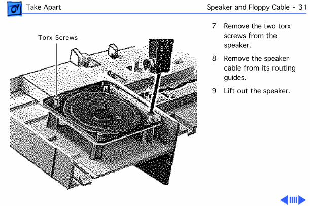
Take Apart Speaker and Floppy Cable - 31
7 Remove the two torx screws from the speaker.
8 Remove the speaker cable from its routing guides.
9 Lift out the speaker.
Torx Screws
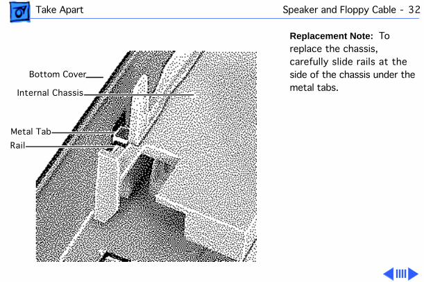
Take Apart Speaker and Floppy Cable - 32
Replacement Note:
To replace the chassis, carefully slide rails at the side of the chassis under the metal tabs.
Bottom Cover
Internal Chassis
Metal Tab
Rail
Take Apart Speaker and Floppy Cable - 33
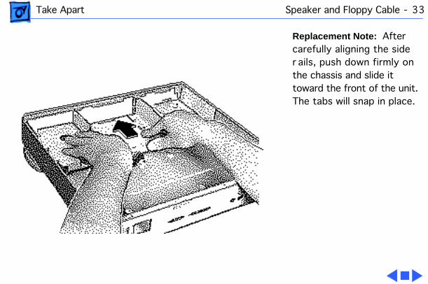
Replacement Note:
After carefully aligning the side r ails, push down firmly on the chassis and slide it toward the front of the unit. The tabs will snap in place.
Service Source
K
Upgrades
Macintosh Performa 6100 Series

Upgrades Expansion Cards - 1
Expansion Cards
Before you begin, remove the following:• Top cover• SCSI hard drive cable
Caution:
Review the ESD precautions in Bulletins/Safety.
Expansion Card Slot
Upgrades Expansion Cards - 2
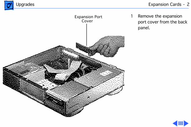
1 Remove the expansion port cover from the back panel.
Expansion Port Cover
Upgrades Expansion Cards - 3
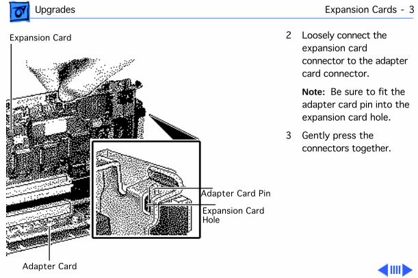
2 Loosely connect the expansion card connector to the adapter card connector.
Note:
Be sure to fit the adapter card pin into the expansion card hole.
3 Gently press the connectors together.
Expansion Card
Adapter Card Pin
Expansion Card
Adapter Card
Hole
Upgrades Expansion Cards - 4
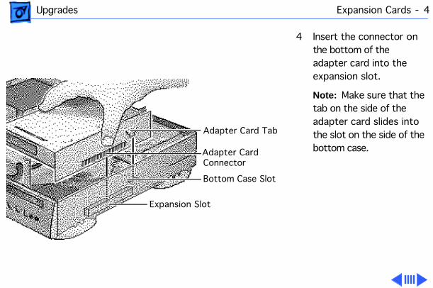
4 Insert the connector on the bottom of the adapter card into the expansion slot.
Note:
Make sure that the tab on the side of the adapter card slides into the slot on the side of the bottom case.
Adapter Card Tab
Adapter Card
Bottom Case Slot
Expansion Slot
Connector
Upgrades Expansion Cards - 5
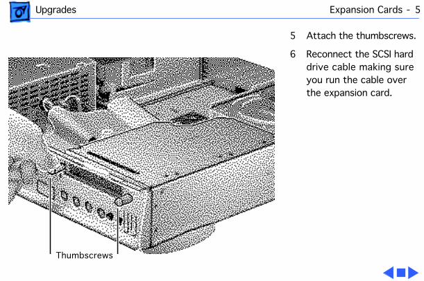
5 Attach the thumbscrews.
6 Reconnect the SCSI hard drive cable making sure you run the cable over the expansion card.
Thumbscrews
Service Source
K
Exploded View
Macintosh Performa 6100 Series

Exploded View 1
Exploded View
Top Cover922-1231
Blank Bezel922-0358
Slotted CD Bezelwith Caddy 922-0805
Slotted CD BezelCaddiless
Power Supply661-1688
Floppy Drive Cable922-0351
SCSI Cable922-0804
Support Column922-0356
Logic Board661-1022
Insulator Sheet922-0808
AV Adapter Cables
RearHousingIO Bezel
922-0720
ExpansionPlug
922-0902
Feet (4)922-0862
Bottom Housing922-0806
CD Audio Cable922-0842
Manual InsertFloppy Drive
661-0121
Internal Chassis
Speaker 922-0353
LED Cable922-0354On/Off Actuator922-0357
CD-ROM Drive661-0913
CD-ROMShield922-0826
FloppyShield922-0809
Hard DriveShield
922-0367
Hard Drive*
Hard Drive Carrier922-0621PDS Adapter
922-0768NuBus Adapter661-0049
Product family configurations may vary. For parts with asterisk, refer to parts list.
Floppy DriveCarrier922-0621
CD-ROM Carrier922-0850