machining «niiig · ebm - electron beam machining 40 edg - electrical discharge grinding 42 edm -...
TRANSCRIPT

RIA-81-U.19
>-;T>
\0\ilMimiO\AI
MACHINING «NIIIG
2ft Newc«aen for Pr«4»ctii»N
MDC 76-101 TECHN IC AL
LIBRARY ■^ .*■> & **..
NBC Machining Process Series;
MACHINABILITY DATA CENTER A DEPARTMENT OF DEFENSE INFORMATION ANALYSIS CENTER
■-■*
1 4 ••

<y
The data contained in this publication have been derived from many sources including tests conducted under conditions which may or may not exist where such data are used. Changes in conditions of processing (machining, fabrication, heat treatment, etc.) and differences in material properties from those described herein may make some or all of the data used inappropriate under the circumstances. Users of the enclosed information are thus cautioned that the information contained herein should be used only as a guide where the user judges it to be appropriate. Metcut Research Associates Inc., contractors to the United States Government, disclaims any and all responsibility for use of the information contained hereby by readers and users of this publication.
The findings in this report are not to be construed as an official Department of the Army position, unless so designated by other authorized documents.
Mention of any trade names or manufacturers in this report shall not be construed as advertising nor as an official endorsement or approval of such products or companies by the United States Government.

YOXITAIHTIONAI.
AIACHINIHC GUIDE
20 Newcomers for Production
Guy Bellows
Publication No. MDC 76 -101
MBC Machining Process Series
MACHINABILITY DATA CENTER
A DEPARTMENT OF DEFENSE INFORMATION ANALYSIS CENTER
Sponsored by ARMY MATERIALS AND MECHANICS RESEARCH CENTER
Watertown, Massachusetts 02172
Operated under Government contract
with the DEFENSE LOGISTICS AGENCY
by Metcut Research Associates Inc.
3980 Rosslyn Drive, Cincinnati, Ohio 45209
Approved for public release; distribution unlimited.

^
ACKNOWLEDGMENTS
This publication was prepared by the MachinabiIity Data Center (MDC), operated by Metcut Research Associates Inc., 3980 Rosslyn Drive, Cincinnati, Ohio 45209. MDC's objective is to collect, evaluate, store and disseminate technical information for material removal operations.
This publication is being sold as contractually required to meet DoD cost recovery goals for Information Analysis Centers. Income received is used to supplement Government funding for operation of MDC to provide services with the objective of increasing productivity and reducing costs for the mutual benefit of Government and industry.
The Center is operated by Metcut under Government Contract for the U.S. Defense Logistics Agency; technical aspects of MDC operations are monitored by the Army Materials and Mechanics Research Center. The support of these sponsor organizations is gratefully acknowledged.
The cooperation and assistance with the editing and illustrations by Modern Machine Shop magazine, in which a large part of this publication appeared, is very gratefully acknowledged. The comments and contribu- tions of the many people throughout industry is also appreciated although limited space precludes listing all their names.
© 1976
by
Metcut Research Associates Inc.
Ci ncinnat i, Ohio
Al 1 r ights reserved
Published 1976. Second Printing 1978, revised
No part of this book may be reproduced, stored in a retrieval system, or transmitted, in any form or by any means, electronic, mechanical, photocopying, recording, or otherwise, without the prior written permis- sion of the publisher.
Printed in the United States of America

CONTENTS
Preface iv Introduction 1
Definitions and Acronyms 2 Active Nontraditional Material Removal Processes 3 Typical Surface Finish Ranges 4 Material Removal Rates 4 Surface Integrity of Nontraditional Processes 6
MECHANICAL Nontraditional Machining 7 AFM - Abrasive Flow Machining 8 AJM - Abrasive Jet Machining 10 HDM - Hydrodynamic Machining 12 LSG - Low Stress Grinding 14 USM - Ultrasonic Machining 16 Surface Integrity Effects Observed in Mechanical Nontraditional Material Removal Processes 18
ELECTRICAL Nontraditional Machining 19 ECD - Electrochemical Deburring 20 ECDG- Electrochemical Discharge Grinding 22 ECG - Electrochemical Grinding 24 ECH - Electrochemical Honing 26 ECM - Electrochemical Machining 28 ECP - Electrochemical Polishing 30 ECT - Electrochemical Turning 32 ES - Electro-stream 34 STEM- Shaped Tube Electrolytic Machining 36 Surface Integrity Effects Observed in Electrical
Nontraditional Material Removal Processes 38
THERMAL Nontraditional Machining 39
EBM - Electron Beam Machining 40 EDG - Electrical Discharge Grinding 42 EDM - Electrical Discharge Machining 44 EDS - Electrical Discharge Sawing 46 EDWC- Electrical Discharge Wire Cutting 48 LBM - Laser Beam Machining 50 LBT - Laser Beam Torch 52
PBM - Plasma Beam Machining 54 Surface Integrity Effects Observed in Thermal
Nontraditional Material Removal Processes 56
CHEMICAL Nontraditional Machining 57 CHM - Chemical Machining 58 ELP - Electropol ishing 60 PCM - Photochemical Machining 62 TCM - Thermochemical Machining 64 Surface Integrity Effects Observed in Chemical
Nontraditional Material Removal Processes 66
Future Nontraditional Machining Processes 67 References 68 Additional Sources of Data 69 MDC Publications and Services 70
MDC 76-101 iii

PREFACE
The author recognizes that the field of nontraditional machining, almost by definition, is a rapidly changing subject. New adaptations, applica- tions or clever techniques are constantly evolving. Some of the pro- cesses still in the laboratory stage can emerge overnight to join the 26 listed and described in this publication. The author will be glad to correspond with others in the nontraditional machining field and to receive information updating, changing or expanding the present process summaries so that future revisions will be improved.
NONTRADITI0NAL MACHINING (NTM) processes are those new material removal techniques that have emerged since the early IS'tO's.
MDC 76-101

INTRODUCTION
Many people have relegated the nontraditional processes to the limbo of the '60's and aerospace. This is no longer true! While many of these unusual processes were first investigated to meet aerospace needs, they are now becoming more prevalent in the automotive industries with a few in appliance applications. Today's status might be capsulized as: yesterday — aerospace, today — automotive, and tommorrow — throughout industry.
Several concurrent trends have brought this about. Design engineers are creating more complex shapes, using less quantity of material but of tougher and more costly alloys, and stressing these parts closer to.the ultimate material capabilities. In response to the designer's needs, materials engineers have created new alloys with greater temperature and strength capabilities. These alloys, however, are also more difficult to fabricate with only a small fraction of the machinabi1ity rating of previous alloys.
At the same time the changing socio-economic scene brings added pressure to the manufacturer of products. Increased reliability, better quality assurance, longer life and lower or more competitive costs are in greater demand, also the sensitive difficult-to-machine materials require more careful processing in order to provide enhanced surface integri ty.
Nontraditional material removal processes will not solve all of these manufacturing problems in one neat, well-packaged solution. They can solve some of them in a cost-effective manner and make possible the manufacture of component parts that formerly were extremely difficult, if not impossible, to machine. Therefore, to stay competitive, it is essential to maintain an awareness of the state of the art of the newly emerged nontraditional processes. This publication provides a brief summary of the 26 most prominent nontraditional machining processes — circa 1976.
TRENDS IN MATERIAL STRENGTHS AND MACHINABILITY
1000° YIELD
STRENGTH KSI
POWDER ^ 200 METAL y^
/'VACUUM
100
n
/ MEIT *
^^KIR - r MElT
_l 1 L 1 1 1 1940 1960 1980 YEAR YEAR 1940 1950 1960 1970
TYPICAL MATERIAL STRENGTH PROGRESS (Nickel alloys for turbine discs)
MACHINABILITY DECLINE FOR IMPROVED W0RKPIECE MATERIALS (Turning with carbide for 30 minute tool life)
MDC 76-101
DEFINITIONS
A manufacturing PROCESS is a purposeful technique utilizing signifi- cantly distinct elements or parameters and/or differing from other processes by at least one order of magnitude (ten to one ratio) in one or more of the major energy modes.
A manufacturing SYSTEM is a sequence of integrated processes applied to a component part, product, or line of similar items that assists in transforming them from an unfinished to a finished state.
A manufacturing METHOD is a specific combination of process parameters that applies to the fabrication of a specific component part or family of similar components.
NONTRADITIONAL PROCESSES is a designation applied to those processes that are emerging or have not been used extensively heretofore. The terminology has a high degree of personal bias depending upon the experience of the individual. They are sometimes labeled nonconven- tional, layless, or nonmechanical. The designation is frequently limited to those processes that have emerged since the early 19*t0's.
ACRONYMS
The acronyms used have been collated with other acronyms used in a comprehensive list of manufacturing processes in order to avoid duplica- tion." Acronyms in current use throughout industry have been retained (due to their familiarity) even though they do not strictly conform to a structured pattern. The advantage of familiarity and recognition of their meanings outweighs the advantages of restructuring them to fit a comprehensive and consistent format. The first publication^ in the Machining Process Series provides a checklist of material removal processes and their acronyms.
MDC 76-101

ACTIVE NONTRADITIONAL MATERIAL REMOVAL PROCESSES
Since the early 19^0's, many new machining processes have emerged which are generally nonmechanical, lay less and involve new energy modes. The 26 nontraditional machining (NTM) processes listed below are those that are in regular productive use and are commercially available— circa 1976.*
MECHANICAL
AFM - Abrasive Flow Machining AJM - Abrasive Jet Machining HDM - Hydrodynamic Machining LSG - Low Stress Grinding USM - Ultrasonic Machining
ELECTRICAL
ECD - Electrochemical Deburring ECDG - Electrochemical Discharge Grinding ECG - Electrochemical Grinding ECH - Electrochemical Honing ECM - Electrochemical Machining ECP - Electrochemical Polishing ECT - Electrochemical Turning ES - Electro-stream STEM - Shaped Tube Electrolytic Machining
THERMAL
EBM - Electron Beam Machining EDG - Electrical Discharge Grinding EDM - Electrical Discharge Machining EDS - Electrical Discharge Sawing EDWC - Electrical Discharge Wire Cutting LBM - Laser Beam Machining LBT - Laser Beam Torch PBM - Plasma Beam Machining
CHEMICAL
CHM - Chemical Machining ELP - Electropolish PCM - Photochemical Machining TCM - Thermochemical Machining
*See MachinabiIity Data Center publication no. MDC 76-100, MACHINING, A Process Checklist for a complete listing of material removal processes.
MDC 76-101

TYPICAL SURFACE FINISH RANGES
Some material removal processes are more adapted to rough initial cuts whereas others are more suited for use as fine finishing cuts. Typical ranges of attainable surface finishes for some material removal pro- cesses are shown in Table I. Additional comparative information is contained in the Machining Data Handbook^ and in American National Stan- dards Institute (ANSI) Standard B^6.1-1962, Surface Texture. s Note that the following chart is an updated version of the chart found in the Second Edition of the Machining Data Handbook.
MATERIAL REMOVAL RATES
Material removal rates provide a general guideline only as an initial step in selection among competing processes. Table II compares the material removal rates of some NTM processes with both conventional (mechanical) turning and abrasive grinding. For those NTM processes which simultaneously cut all exposed surfaces, the penetration rate is a more significant value. Part of this data was extracted from Electro- chemical Machining by DeBarr and Oliver.5
Table I
TYPICAL SURFACE FINISHES FROM NONTRADITION AL MATERIAL REMOVAL PROCESSES Average Application
Less Frequent Application tv.agj.-a Surface Finish, arithmetic average in microinches
500 250 125 63 32 16 8 4 2
AFM a«S* jBafi LSG Y-X-]':: sra USM mmt ms CHM/PCM ■ ' te^HK - 1 •' i"
[•'';£'£ ELP BOB :'\S-''
EBM/LBM M aHSg-H 1 DC ^m^-»s war EDM roughing
EDM finishing
PBM
■■i ■- •;■■-. AM
8BS mSi Liiiii fctii
ECD/ECP ^^ ̂ ™ ■. .
ECG
ECH
ECM frontal cut; ECT
SSS3* S88S «Maw ftfiS JtxSz
ECM side cut £-;Vr: ^m ^K*-it ■•-.- ','•■'■* ■'■'■'■
jfij&i
ES p£HHI^MH£^--:-j IM STEM ^■*m mmm^
MDC 76-101

.a
< a. —i < > o UJ tx —i <
. *- 3 k. Q. 4>
s o 'a. K
at
5 o LT> o LD O LD o O 1 c <u n CM o <—1 o i-H i-H CM 1
H
s o
CM CM 1
E
TO > 3 o E E OJ o CM CM LT) i—t »—t LO CM
m 1 o:
CM O O 8 o o o © ^ (T3 or o o .—t o o o o o
S TO o o o o o o o o o
>> u 2
< s 3 H 0> IT! LD
< -O TO C TO e
m O t—< un CM CM in in o o
o CM o o
o o
O O 8 8 8 o o O o o O o o o
o o O o o o o o d <
V c 3 o C T-H 'S oi 'E CM o k_ TO \ t 1 in ir> o o 5 c o:
01 1 1 c o o o CD »1- o a> .c I—*
a. c
Ol •*- an _ 3
c '•S 1 C
E o o t—1
o i i i
i 1
Q o 1 1 1 1
3 a. ^ CM i CM 1 1 o </) 1
o> ■*-
c 3 o C
O ai Q. E _, o o o o o O o E 3
"V. i-H CM ^J- CO o O O 1 9- o £ r—* CM o O 1 ^ Q.
C o o a.
o O 1 CO
_ ~* 41
II • 3 in CO <n C o o >
E LO o o o co O o o X O 1 o o o o j—t d d d o s is
a. IT U c
o CM
ir> i-4 CO
TO m c c o o
l/> c BO c an c
1 c
c c 51
c c s 5 s 5 S s s o 3 o § £ Q Ü to m CO x
a. o 1- o LÜ UJ o UJ _l o
MDC 76-101

SURFACE INTEGRITY OF NONTRADITIONAL PROCESSES
Surface integrity is a subject covering the description and control of the many possible alterations produced in the surface layer of a mate- rial during manufacturing including their effects on the material properties or on the performance of hardware.^ The objective of surface integrity is the development of unimpaired or enhanced surface condi- tions in hardware by controlled manufacturing processes. The principal causes of alterations from material removal operations are:
1. high temperatures or high temperature gradients 2. plastic deformation 3. chemical reactions on the nascent machined surface k. excessive heating from electrical conductance.
Distortion, inaccuracies or change in material properties are of concern to the designer and manufacturer because they reduce quality and are a source of added cost or potential losses. Some of the effects can also contribute to the initiation of early component failures. Changes in material surface properties can in turn influence mechanical properties of which fatigue life and stress corrosion resistance are of the most concern. ?jfl
Well developed methods for evaluating surface integrity exist today,9>10 but data is only slowly accumulating upon which to draw guidelines and uncover trends or patterns. These guidelines, however, must be considered only as general or starting recommendations. Each material- process combination is unique and can have variable effects depending on the metallurgical state of the material and upon the energy intensity level used during processing. The designer should assess the critical areas on the workpiece and apply surface integrity specifications to these areas only — or otherwise component costs may be excessive. The manufacturing engineer in turn should realize that maintaining the proper sequence of operations is as important to surface integrity as is the selection and precise maintenance of the correct process operating parameters.
It is now well established that all material removal processes have some impact on material properties — the conventional mechanical processes can have effects as severe as those caused by NTM processes.^>H Only the specific application and use of the workpiece can determine whether the surface integrity effects are beneficial or detrimental.
The depths of the altered material zones (AMZ) typical to the four groups of NTM processes have been tabulated from data in MDC's surface integrity files. Surface integrity effects are summarized in a table following each group of processes with the same principal energy mode.
MDC 76-101

MECHANICAL NONTRADITIONAL MACHINING
Mechanical material removal was used with man's first identifiable tool — the chipped flint "knife". Now — two mi 11 ion years later — new mechanical material removal processes are still emerging. Those that have come into active commercial use since the early 19A0's qualify for nontraditional status.
Mechanical Nontraditional Machining Processes
AFM - Abrasive Flow Machining AJM - Abrasive Jet Machining HDM - Hydrodynamic Machining LSG - Low Stress Grinding USM - Ultrasonic Machining
Although a host of new tool materials add significantly to conventional chip cutting processes, these processes are still considered conven- tional. Turning with cubic boron nitride tools, which develop high temperatures during cutting, almost qualifies as hot machining. Pro- cesses using these tools, however, are not included because external heat is not applied.
The mechanical NTM processes that have emerged have one facet in common — all involve multipoint cutting. Utilization of multipoint contact between the "tool" and the workpiece is a distinct aid to productivity. This attribute is needed to offset the slower rates of material removal that frequently accompany the unusual capabilities of the mechanical NTM processes.
Detailed descriptions of each process follow and all of the mechanical NTM are listed in alphabetical order. Surface integrity effects resulting from the mechanical NTM processes are summarized in Table III, p. 18. The electrical, thermal and chemical NTM processes are similarly grouped together.
MDC 76-101

ABRASIVE FLOW MACHINING AFM
Upper Media
r\ A Chamber
i? $
Fixture
rkpiece
L Flow
M V, %
.
H <$ Viscous Abrasive Media
Lower Media
Chamber
Abrasive flow machining (AFM) is the removal of material by a viscous abrasive media flowing, under pressure, through or across a workpiece. Hardened steel tooling directs the flow so that the major restriction occurs where material removal is desired. Ceramic or urethane inserts can minimize the tool wear that is experienced in some cases. Media flow rates range from a few gpm to 60 gpm. Generally, the media is extruded through or over the workpiece with motion in both directions using up to several hundred reversals per fixture load. Pressures range from 100 to 1600 psi. Aluminum oxide, silicon carbide, boron carbide or diamond abrasives are used with grain sizes ranging from No. 8 to No. 700. The velocity of the extruded media is dependent on the principal parameters of viscosity, pressure, passage size and length.
PRACTICAL APPLICATIONS Edge finishing, radiusin removal are accomplished process, but is particul ible internal passages, alloys are being machine from thermal processes ( Polishing can improve 30 the original roughness, produced. Holes smaller cult to process with AFM
g, deburring, polishing and minor surface with AFM. It is not a mass material removal arly useful for polishing or deburring inaccess- Materials from soft aluminum to tough nickel
d with AFM. Removal of undesired recast layers EDM, LBM, nitriding) is also achieved with AFM. - to 300-microinch AA finishes to one-tenth of Radii from 0.001 inch to 0.060 inch can be than 1/64 inch in diameter are sometimes diffi-
Blind-hole polishing is impractical.
MDC 76-101

ABRASIVE FLOW MACHINING AFM
MATERIAL REMOVAL RATES AND TOLERANCES AFM processing times frequently range from one to five minutes. Stock removal can be uniform within 10 percent of the stock removed; it is uniform within each passageway but out-of-roundness will not be corrected. Surface finishes to 2 microinches AA can be attained and dimensional tolerances to a few ten-thousandths inch can be achieved. Where passageways of dissimilar size are adjacent, stock removal will also be dissimilar, but fixture design can sometimes provide compen- sation. Control of the volume of media flow is of major importance to quality control. More uniform deburring than hand work is a significant quality advantage. Careful post-operation cleaning to remove the media i s recommended.
AVAILABILITY Low-, medium- and high-pressure systems are available in the range from 100 to 1600 psi. Many types of abrasives and viscosities are available as media. Tooling is usually needed to direct, confine or sometimes control the flow paths. Many small parts can be processed simulta- neously but each should be held individually. Production rates of 1000 pieces per hour for multiple-fixtured small parts have been achieved. Part sizes range from 0.1 inch to over kO inches in diameter.
Before AFM
After AFM
Burr removal in 30 seconds by AFM of k^kO steel retainer ring. (Courtesy of Extrude Hone Corp.)
MDC 76-101

ABRASIVE JET MACHINING AJM
Vibrating Powder Supply
Abrasive jet machining (AJM) is the removal of material through the action of a focused stream of grit or powder-loaded gas. The gas can be clean dry air, nitrogen or carbon dioxide under modest pressure (30 to 120 psi). The abrasive is silicon carbide, aluminum oxide or glass grit, which impinges on the workpiece at velocities up to 1000 fps through the guidance of a hard wear-resistant nozzle. Nozzles are made of tungsten carbide or sapphire. A dust hood or vacuum nozzle is needed to collect the chips and abrasive grit. Vibration of the grit/powder container is desirable to secure uniform flow. Automated nozzle or workpiece motion control or hand-held control is used. Cutting is controlled by gas pressure, closeness of nozzle to workpiece, type of abrasive, abrasive flow rate and time. Masks of copper, glass or rubber are sometimes used to control overspray.
PRACTICAL APPLICATIONS Hand-held polishing, deburring, etching and radiusing are accomplished; however, a constant motion of the nozzle is necessary to prevent exces- sive erosion or grooves. Intricate shapes or holes can be cut in heat- sensitive, brittle, thin or hard material. Scribing, grooving, etching and cutting of ceramics is frequent. Suitable cleaning after use is necessary to remove grit from small crevices or internal passageways. Delicate cleaning, such as the removal of smudges from antique docu- ments, is also possible with AJM.
MATERIAL REMOVAL RATES AND TOLERANCES AJM is not a mass material removal process — it is a finishing process. The typical removal rate for plate glass is 0.001 cubic inch per minute with finishes in the 10- to 50-microinch AA range. Practical minimum cut width is 0.005 inch. Tolerances to +0.002 inch are possible; a minimum radius of 0.00'* inch is practical. Taper is present in deep cuts.
10 MDC 76-101
ABRASIVE JET MACHINING AJM
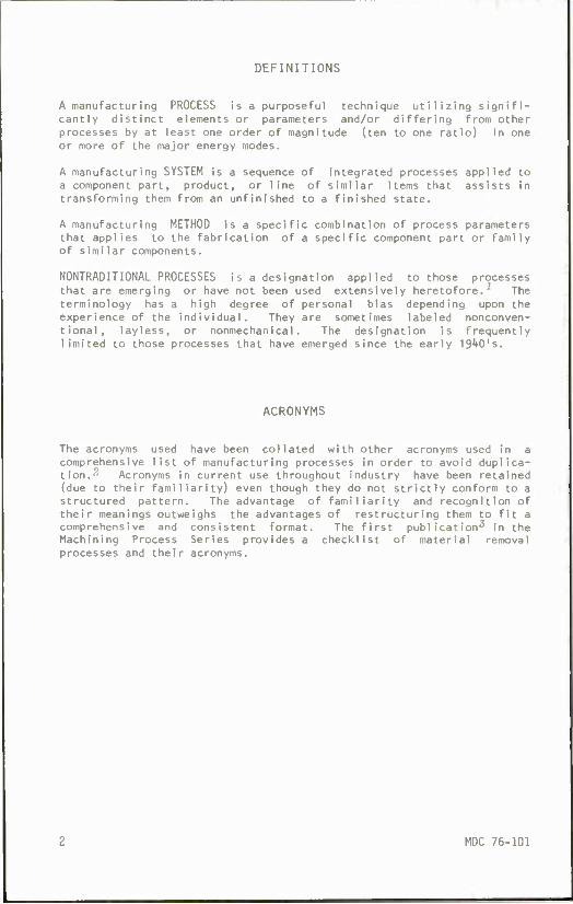
AVAILABILITY Commercial bench-mounted units are available for a modest cost. The principal investment includes the automatic controls, the motion- producing devices and the dust-collecting methods. It has been found to be inefficient to reuse the powders.
AJM Work Station.
MDC 76-101 11
HYDRODYNAMIC MACHINING HDM
Intensifier
Controls
Valve
Sapphire Itole
Workpiece
U7WIA Dram 1
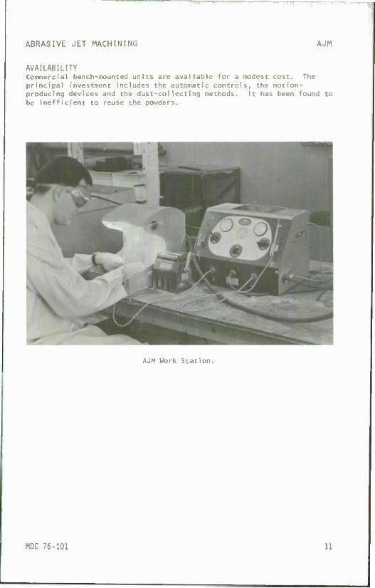
Hydrodynamic machining (HDM) removes material by the impingement of a high-velocity fluid against the workpiece. The coherent jet of water — or water with a long-chain-polymer additive such as polyethylene oxide — is propelled up to Mach 2 speeds by the 10,000 to 60,000 psi typical pressures. Direction and control of the 0.002- to 0.040-inch- diameter stream is through a sapphire nozzle. Standoff distance of the nozzle from the workpiece is important. Relatively small volumes of fluid are used (1 to 2 gpm). The fluid is elevated to the desired operating pressure by a hydraulically driven intensifier with an accu- mulator to smooth out the pulses. The jet fluid is a nonwearing tool with no frictional drag in the cut and virtually no forces at right angles to the jet, thereby minimizing holding-fixture requirements. The kerf is insensitive to dwell of the jet and there is essentially no dust; therefore, explosion and fire hazards are reduced. Air entrapped in the jet stream can create considerable noise on some materials. The noise level increases with standoff distance; 1/8 inch is a practical minimum. The drain should be close to the workpiece. Stringent fluid filtration improves nozzle life; hydraulic seals are reasonably durable.
PRACTICAL APPLICATIONS The ability to cut soft nonmetallic materials in any narrow kerf (except double-knit fabrics) leads to fo tions. The absence of heat-affected zones allows th in the wood and paper-products fields, such as cutti ceiling tile at 250 fpm using a 45,000 psi jet. Fur inch laminated paper board, 1/2-inch asbestos brake 3/4-inch-thick shoe sole material have been cut with urethane foam, Styrafoam, 1/8-inch plywood, rubber, and fiber-glass-reinforced plastics are also among t cut. Some work has been done with 0.005-inch steel aluminum; however, cutting these materials with HDM up to 100,000 psi .
posi tion with a rm-cutting applica- e process to be used ng 3/4 inch acoustic niture forms of 1/2- shoe 1 inings and HDM. Gypsum board,
nylon, fiber glass he materials being sheet and 0.020-inch requires pressures
12 MDC 76-101
HYDRODYNAMIC MACHINING HDM
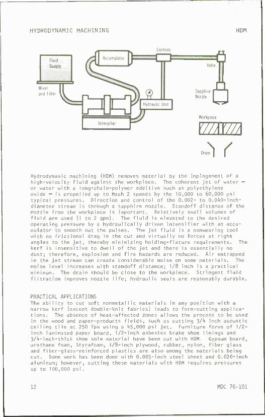
MATERIAL REMOVAL RATES AND TOLERANCES Cutting rates depend on the workpiece material; values to 6000 fpm have been attained on paper products. Crushable materials can be slit with high quality edges. The narrow kerf aids material savings while the lack of sensitivity to dwell allows contours to be controlled as accu- rate as the workpiece or nozzle motion control. The kerf is about 0.001 inch larger than the orifice utilized.
AVAILABILITY Standard components are available; however, a complete machine tool package is not regularly available. Each application is engineered to meet the requirements as found by sample test cuts made to determine the values of the key parameters of cutting speed, pressure, nozzle size, standoff distance and type of fluid. The high-pressure water jet does not wear or require sharpening as compared to conventional slitting operations. Dust collection equipment is unnecessary. The hydraulic pumps are enclosed to reduce noise to tolerable levels.
Acoustic tile cut at 250 fpm. (Courtesy of Flow Equipment Co.)
MDC 76-101 13

LOW STRESS GRINDING LSG
In Feed* Cross Feed
'///////^^7))nni\ •Table Motion
Low stress grinding (LSG) is an abrasive material removal process that leaves a low magnitude, generally compressive, residual stress in the surface of the workpiece. Conventional grinding typically leaves a high tensile stress in the workpiece with increased distortion or a reduction in the high-cycle fatigue strength. Precise control of the following grinding parameters is essential:
Frequent coarse wheel dressing to maintain sharpness Lower wheel speeds (under 3500 sfpm) Lower infeed rates (0.0002 to 0.0005 inch per pass) Oil-base lubricants with good flow control Soft wheels (H, I or J grades) Higher table speeds (50 sfpm or more) Solid fixtures and well-maintained equipment
These conditions reduce the heat shock and plastic deformation to manage- able levels. Good control of all parameters must be maintained. If one of the parameters cannot be achieved on a specific machine, it will be necessary to be more stringent on all of the remaining parameters.
PRACTICAL APPLICATIONS LSG should be considered when higher quality surfaces are required. Its controlled finishes, minimal distortion, minimal residual stress and enhanced surface integrity are particularly useful on surfaces subjected to high cyclical stress or stress corrosion. A principal use for LSG is the preparation of test specimens for evaluation of material properties. By using LSG, heat-sensitive alloys can be prevented from cracking during fabrication. Residual stress checks or distortion checks are suitable methods for evaluating the attainment of low stress conditions.
MATERIAL REMOVAL RATES AND TOLERANCES While material removal rates are low, good productivity can be attained by successively reducing conventional material removal rates to LSG levels as the desired finished dimensions are approached. Finishes from 16 to 32 microinches AA are typical with +0.0005 to +0.0002 inch tolerances usual .
AVAILABILITY Any grinding machine or any form of conventional abrasive grinding can be modified to operate in a low-stress mode of operation.
14 MDC 76-101

LOW STRESS GRINDING LSG
Stress pattern during grinding. (Courtesy of Huebner Publications)
^ O
+ 100
+ 80
+60
CO CO LU
I— CO
—i
9 00
§ +40
+20
z o CO CO ■20
-40
• • • • • •
1 1 1 RESIDUAL STRESS IN AISI 4340
• • • • • X
SURFACE GRINDING
• •
• • ZONVEr -ITIONA L
• • •
,/ ^LOW STRESS
1 1 0 2 4 6 8 10 12
DEPTH BELOW SURFACE - INCHES X 10"3
MDC 76-101 15

ULTRASONIC MACHINING USM
feed
Abrasive Slurry
I U I Coils I I Magnetostrictiv
LTT\
-O High Frequency ■O Power
Tank
Ultrasonic machining (USM) is the removal of material by the abrading action of a grit-loaded slurry circulating between the workpiece and a tool vibrating at a frequency above the audible range. A high-frequency power source activates the stack of magnetostrictive material, which produces the vibrating motion in the toolholder. The tool forms a reverse image in the workpiece as the grit-loaded slurry abrades the material. Frequencies of 20 to '(O kilohertz with amplitudes of 0.0005 to 0.00't inch are most commonly used. Boron carbide, aluminum oxide and silicon carbide are the most frequently used grits with grit sizes ranging from No. 100 to No. 800. It is important to maintain a full flow of slurry (usually cooled) in the 0.001- to 0.005-inch cutting gap. Overcut is approximately equal to twice the size of the abrasive grit. Surface roughness increases with the size of the grit. The tools — made from brass, tungsten carbide, mild steel or tool steel —will wear from the action of the grit with a ratio that ranges from 1:1 to 1000:1 (work- piece to tool wear), depending on the materials involved. The tool must be designed to resonate at the desired frequency for best results and must be strong enough to resist fatigue failure.
PRACTICAL APPLICATIONS While USM can cut any material, conductive or nonconductive, metallic, ceramic or composite, it is most effective on materials harder than kO Rc. Holes, slots and irregular shapes can be produced in delicate ceramics. Over 2,000 holes, 0.031-inch square, were "drilled" simulta- neously in O.O'tO-inch-thick carbon in less than 10 minutes. A 1/4-inch- diameter hole can be drilled 5 inches deep in glass in 130 seconds with a rotating ultrasonic tool. To achieve resonance the tool size is limited to about 3-1/2 inches diameter currently. Tool wear and taper in the cut can be limiting with practical depth-to-width ratio being 2.5:1. Threading of ceramics can be accomplished with a rotating tool and workpiece. Coining, lapping, broaching and deburring are also done with the ultrasonic process. Ultrasonic assist is sometimes helpful as added energy to conventional drilling and drawing. Ultrasonic welding has been applied to plastic assemblies.
16 MDC 76-101

ULTRASONIC MACHINING USM
MATERIAL REMOVAL RATES AND TOLERANCES The removal rate is slow and depends on the ability to circulate the slurry; the rate is inversely proportional to area of cut and propor- tional to grit size and the square of the amplitude of vibration. For glass, a penetration rate of 0.150 inch per minute with a 1/2-inch- diameter tool proceeds with a 100:1 wear ratio when using a low carbon steel tool with a 35 percent slurry of 200-grit boron carbide vibrating at 25 kHz and 0.0015 inch amplitude. Finish improves with smaller grit size and can be in the 10- to 40-microinch AA range. Accuracy is typically +0.001 inch and can achieve +0.0005 inch. Break-out and chip- ping of exits can be a problem. Thin parts are often cemented to a sacrifice plate. Surface integrity is good and the compressive layers can enhance fatigue strength.
AVAILABILITY Equipment for cavity and hole sinking is available as are rotary heads with axial ultrasonic vibration. A portable ultrasonic drill is pro- duced and used on aircraft assembly lines. Currently, a 3-1/2-inch- diameter tool is the largest in use.
100
c/5
CO
(- oo
USM
MILLED
ANNEALED SHOT PEENED
AS ROLLED CHM GROUND
EDM
107 CYCLES
Fatigue Endurance Strength of 5Al-2iV Titanium Alloy. USM compared to other processes. (Source: AFML report WADC-TR-57-310)
MDC 76-101 17

o
o LU a: _J
o
oi
in 1 c o
■M — o ■o i/\ c 04 o O o u LA
X) L.
— r^ rA o o LA 1 -3- O LA o 4J
1 1 •- ooo en CM 1 O vD CM 03 LA
"O CM <n C c\ 1
(D ■M CO </> U- 4- o
vt i_ <u
<D E fD 1_ u\ fO CM a.
ro CM
in \£> V) Ml/Mft in LA lA 1 IMUM— o 1) i i 4J
U o o — o o O 1 o o o o -* o 1_
Q_ — *~ (D U
a >- \- 1_
01 >- ro _l
in 01 4-1 4-1 , , o in 10
csl C 10 o 10 o in
5 a. L- 01 01 »— 01 in en 3 X. c
i/> i/i 3 O L- ID a> in ^- *J — o > £ u J< < 0 4J O ^Xi U a L. (o^. c a ai ID - a E N jr;
a. o i_ — L. < o ~-~ +- u -OX L. -a o ^ um-^ o c o> c l_ o 4-f in ■o •— o E 0 o 10 — C 01 C =fc z — i_ — ID "» c -I-» a. <o c ID
4J O 4-i I O 4-1 i- o x: oi 1 ID M- ID in — < -I- tvl Z 1-
E 0) L. L. in 4J X 3 oi +J L O 01 o oi ro L. O — "O E 4-. OI C O 4-> L. N 10 +-» 10 0) O ID
4-> C 0) M- >~ — 1/1 4-> — — 01 O *J 1- L. u 10 3 01 — < .* LO — 3 •— U 14- 01 0) CC IT Q *- u — C 01 OI 01 a.
M- 01 ID in ra — (0 10 > L. 14- 01 E H- a» >- Ü O in L- HI 4-» L. — 3 M- en 01 LÜ oi Li- ._ — 0) U 3 in ai 4J — <t C 4-1
ra 4J 4J c o -o >. L. O — 1 ID M- L- W in in T3 i_ .- L- 01 01 10 4-1 J: E 0 01 in fl) ttj 1_ O i/> O 4-» — 4-1 10 O 0
> 01 — — ID .- oi 01 C 01 01 0) cc — i/i x: x
0 0) < -i O O-I s: a: *4? I_ CL >^ 1-
in in
oi 3
c -K 4-»
X 10 a) 10 u_ 3 o O .— •— 01 £ 01 O)
o — l_ — o 01 — -am 3 TJ 10 >- u c oi — _ 01 — •• o ID ID u L. in — i_ i- in
H- X o> oi 01 10 01 0) 01 -C Li_ i_ O 4J 4J c 4J 4J 4-) C OI o 3 01 — ID o oi — io o — X (/i X < H r-J X < Z M X
X +1
a> — ai E
— 0) C VI t_ s < ) (1) — c > +- Ul '1 IZ 11 i- <D a> Ul
+- Q. ro Jj: in — M- (') Zl O T3 l/l
-Q «* C Zl
_l
^*~ o <1 r O ^~ L
m 0
L -i +- o in C in ■n
11) — tli 0) m in L- 01 i) ra J«: +- in <a > in n • M- — O
■o 1_ Zl CM i Hi ID n cx n L 4- in 0) c <J it) (I) <D 1_ -C H U) Q. -C o +■ n 111 • X +- —- L -1
111 HI in M- — - 4~ <) I) in m —. III +■ +- £T 41 "O > m ■o <) 0) in
IZ in +- (i) m +- 5 +- in ro in L r l_ b l_ c: L. ill +- HI I) L. .„ .— in r in — <> <) ro IZ h- u in C a. L 111 — 01 .'.i cn IU
O c 4- C in 1 „ L O ro m HI ri- — <B () (> tn h ll) 0 >
in iii a. — n 0 i) Hi i_ ■ > O m c c -i HI L in
in in a (I) +- © in in x: m m L. O L. <!> <n +- in Hi in ro Cl Q- +- +- -o P t- in HI ro c o HI ai m o i i i i ro o 111 L. r <J — — in in Ul 4- —• >- ii T3 Z) n HI (II 4- — OI t C n r Ul — c
-C in ') (11 ID — +- in L. m 4- C O ill <1) ill (11 Zl O c
c r [ T) li — ID ;i X3 — T-l () — ( > in -c ro ro L u 1/1 r ID C +- +- in III i' HI O ai
JZ r 1- 8V (li 0) 4- H o c ^z CL <;i «1 L. 3 4- -H a> L n L. M- L. XI
a ai 8 H) 0 r C r :- III ■o — — T3 i c
V =: 0)
-1 ai ai c c
z^ > 4- +- — •— •— c 1 L. r t- [Z ro n ID ai 1 CD — 11 —. > in -I- — 1 in (i L (> .- 01 n iZ)
n !_L *" ex
L i 0 i < n ii f) in 8 CL "4-
t- \- in 4- 4- o u +- (11 . i ai i c i_ C H) T) C 4-
4- HI t- I. r — C ' X 1 1 > ri (1 ro X 3 4- ro HI c H) 1 SS II •• 11 (1 r ) Ul — ^. » 4- o IM — «= E ro
18 MDC 76-101

ELECTRICAL NONTRADITIONAL MACHINING
Nontraditional machining (NTM) processes have involved manufacturers in new and unusual forms of energy. In all the NTM classifications the process has been listed by the energy mode that is the principal means for material removal. In many cases there is more than one mode of energy at work. This is true of the electrical NTM processes where electrolytic dissolution (which is based upon the Faraday laws of electrolysis) is predominant. There are other electrical NTM processes that are not electrochemically oriented, but they are not commercially available. The list below covers those that are available — circa 1976-
Electrical Nontraditional Machining Processes
ECD - Electrochemical Deburring ECDG - Electrochemical Discharge Grinding ECG - Electrochemical Grinding (sometimes ELG) ECH - Electrochemical Honing ECM - Electrochemical Machining (Milling) ECP - Electrochemical Polishing ECT - Electrochemical Turning ES - Electro-stream STEM - Shaped Tube Electrolytic Machining
All of these active electrical NTM processes abandon the "brute force and violence" of conventional machining for the "cool, steady, non- deforming magic" of the highly focused deplating action of electro- chemical machining. This atom-by-atom material removal introduces no stress into the workpiece. Surface integrity effects resulting from the electrical NTM processes are summarized in Table IV, p. 38. The electri- cal nature of these processes does confine their use to electrically conductive workpiece materials. The wide spread availability of "clean" electrical power also commends the electrical NTM processes to the modern manufacturing engineer.
MDC 76-101 19

ELECTROCHEMICAL DEBURRING ECD
Stationary Cathode
DC Power Insulation
Overload Protection
e
Heat Exchanger
-L<.cnc<g^] Electrolyte Supply
Electrochemical deburring (ECD) is a special version of ECM; it was developed to remove burrs and fins or to round sharp corners. The stationary cathode is shaped and positioned so that there is a narrow gap, typically 0.005 to 0.050 inch, between the cathode and the burred surface. Normally, only a small portion of the cathode is exposed for maximum concentration of the electrolytic action. The direction of electrolyte flow is usually arranged to carry away any burrs that may break loose from the workpiece during the cycle. The electrolyte flow is a modest 1-lt gpm per 100 amperes at low pressure (15 to 50 psi). The voltage is typical of ECM, 7 to 25V dc. The current requirements are low; about 15 amperes per linear inch of edge is sufficient. An electro- lyte solution of 1 pound of salt per gallon of water at 100°F is satis- factory; a 2 to 3 pound-per-galIon sodium nitrate solution can reduce corrosion. Multiple fixtures are usually used with the absence of feed motion on the cathode tool, thus simplifying the basic equipment.
PRACTICAL APPLICATIONS Almost any conducting metal can be deburred electrolytically. Most electrolytic deburring is done in seconds where hand deburring would take minutes. Applications have included automotive connecting rods, gear teeth, blanking dies, valve ports, nozzle intersecting holes, and punch press blankings. Interior and hard-to-reach burrs or fins also can be removed with special, exactly located electrodes.
MATERIAL REMOVAL RATES AND TOLERANCES Most deburring occurs in 5 to 50 seconds. Longer "on" times can produce a rounded corner in addition to deburring. By insulating the cathode, effects on other exposed areas of the workpiece are reduced to negli- gible amounts. The highly focused electrolytic action usually results in smooth finishes - better than 6*t microinches AA and, with higher current densities, as smooth as 10 microinches AA.
20 MDC 76-101

ELECTROCHEMICAL DEBURRING ECD
AVAILABILITY Several builders supply ECD equipment or systems. Stainless tooling is usually used to resist the electrolytes. Most fixtures are for multiple parts and the controls are automatic for the full deburring cycle. Floor-to-floor time is principally determined by the loading and unload- ing time. The equipment is usually smaller and less complicated than that used for conventional ECM.
ECO fixtures for deburring connecting rods at 100 amps. (Courtesy of Anocut Inc.)
MOC 76-101 21

ELECTROCHEMICAL DISCHARGE GRINDING ECDG
Site of Random Discharge
Electrochemical discharge grinding (ECDG) is a combination of two mate- rial removal processes, ECG and EDG, with a slight modification of each. Sometimes this process is called ECDM, electrochemical discharge machin- ing. The principal material removal comes from an electrolytic action at low-level d-c voltages; however, no physical contact occurs between the wheel and the workpiece as in ECG. Electrical discharges from the graphite wheel are initiated from the higher a-c voltage superimposed on the d-c circuit. Sometimes a pulsating d-c voltage is used. The breakdown of an anodic film at random sites on the workpiece guides the electrical discharge action. The gap voltage is controlled to about 8V; lower values enhance abrasive wheel wear while higher values increase cratering of the wheel and the workpiece. A warm sodium nitrate solu- tion (1-1/2 to 2 lb/gal of water) is commonly used as the electrolyte. A uniform supply to the wheel/workpiece interface is promoted by closely formed scrapers. Good results are obtained with currents of 500 to 600 amperes per square inch at k to 12V dc with 300-mesh graphite wheels running at 1(000 to 6000 sfpm. A 200-ampere, 12V 60 Hz a-c power supply is adequate to maintain a gap of 0.0005 to 0.0015 inch when wheel-to- workpiece pressures are 5 to 20 psi.
PRACTICAL APPLICATIONS Almost any electrically conductive metal can be ground successfully; dressing of carbide inserts is a good application. Plunge, surface and form grinding are practical. Tolerance improves through the use of formed auxiliary plastic or graphite scrapers. There is less wheel wear and dressing as compared to EDG.
22 MDC 76-101

ELECTROCHEMICAL DISCHARGE GRINDING ECDG
MATERIAL REMOVAL RATES AND TOLERANCES ECDG will remove about one cubic inch of tool steel per hour, which is about 5 times faster than EDG, but more current is used. Dimensional accuracy, less than EDG, is +0.0005 Inch with close control and +0.001 inch for routine production. Finishes are better — 5 to 15 microinches AA for carbide and 15 to 30 microinches AA for steel.
AVAILABILITY Commercial equipment is available; capacity ranges from 20 to 2000 amperes dc.
MDC 76-101 23

ELECTROCHEMICAL GRINDING ECG
Electrolyte
Insulating —^a^ Abrasive pr Particles
Nozzle
Tank ^
Constant Feed
| Insulate I I Spindle
0
P Fixture
vmmr Rotating Conductive Wheel
DC Power
0
Pump
Electrochemical grinding (ECG) is a special form of ECM in which the conductive workpiece material is dissolved by anodic action and any resulting films are removed by a rotating, conductive, abrasive wheel. The electrical gap between the wheel and the workpiece is determined by the abrasive particles since they protrude from the wheel about 0.001 inch. The space between the workpiece arid the wheel must be filled with electrolyte at all times. A close fitting nozzle box directs the electrolyte flow so that it is drawn into the gap by the feed and rotary motions. Sodium nitrate (1 to 2 lb/gal of water) is frequently used as the electrolyte; other salts of various degrees of corrosiveness are also used. Some electrolytes also include a rust inhibitor. Direct current is supplied to the wheel via slip rings on the insulated spindle. Wheel speed varies from 4000 to 6000 sfpm. The wheel/work- piece contact area is critical and current density in the gap is the principal feed-controlling factor. Typical current values range from 500 to 2000 amperes per square inch. Maximum contact arc lengths are about Ilk to 1 inch to prevent overheating the electrolyte.
A typical set of operating values are 1000 amperes per square inch for 1 inch-per-minute feed on a 0.1-inch-deep cut operating at 6V with a 5500 sfpm wheel speed and a 2 gpm electrolyte flow. These conditions can produce as much as 150 psi pressure between the wheel and workpiece so rigid tools, fixtures and spindles are required to minimize deflection. The abrasive in the wheel scrapes away any films formed on the workpiece so that clean surfaces are available for good electrochemical action. The abrasive work should be less than 10 percent of the material removal and preferably less than 5 percent with some applications as low as 1/2 percent. The fastest material removal is obtained by using the highest attainable current densities without boiling the electrolyte. Equipment and tools should be washed down thoroughly after each use. Areas adja- cent to the wheel are exposed to the conductive spray and can be pitted by the low current densities present there.
24 MDC 76-101
ELECTROCHEMICAL GRINDING ECG
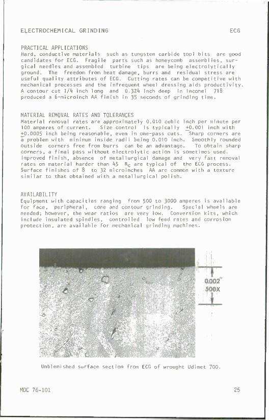
PRACTICAL APPLICATIONS Hard, conductive materials such as tungsten carbide tool bits are good candidates for ECG. Fragile parts such as honeycomb assemblies, sur- gical needles and assembled turbine tips are being electrolytically ground. The freedom from heat damage, burrs and residual stress are useful quality attributes of ECG. Cutting rates can be competitive with mechanical processes and the infrequent wheel dressing aids productivity. A contour cut 1/4 inch long and Q.'ilk inch deep in Inconel 718 produced a 6-microinch AA finish in 35 seconds of grinding time.
MATERIAL REMOVAL RATES AND TOLERANCES Material removal rates are approximately 0.010 cubic inch per minute per 100 amperes of current. Size control is typically +0.001 inch with +0.0005 inch being reasonable, even in one-pass cuts. Sharp corners are a problem with minimum inside radii being 0.010 inch. Smoothly rounded outside corners free from burrs can be an advantage. To obtain sharp corners, a final pass without electrolytic action is sometimes used. Improved finish, absence of metallurgical damage and very fast removal rates on material harder than k5 Re are typical of the ECG process. Surface finishes of 8 to 32 microinches AA are common with a texture similar to that obtained with a metallurgical polish.
AVAILABILITY Equipment with capacities ranging from 500 to 3000 amperes is available for face, peripheral, cone and contour grinding. Special wheels are needed; however, the wear ratios are very low. Conversion kits, which include insulated spindles, controlled low feed rates and corrosion protection, are available for mechanical grinding machines.
Unblemished surface section from ECG of wrought Udimet 700.
MDC 76-101 25

ELECTROCHEMICAL HONING ECH
**^> Mechanical Honing Motion
Electrochemical honing (ECH) is the removal of material by anodic disso- lution combined with mechanical abrasion from a rotating and reciprocat- ing abrasive stone (carried on a spindle which is the cathode) separated by a flowing electrolyte. The principal removal action comes from the electrolytic action with the abrasive stones being used to maintain size and a clean surface. The electrolyte gap is maintained at about 0.005 inch by the nonconducting stones, which are bonded to the expanding arbor with cement. The cement must be compatible with the electrolyte yet provide insulation for the low d-c voltage of 6 to 30 volts. The current density is between 100 to 300 amperes per square inch. The electrolyte pressure is about 75 to 150 psi.
Electrolyte composition, frequently sodium nitrate, is not as critical as for ECM because of the cleaning action of the stones. Tooting (for controlling the flow path and for positioning) and machine components must be fabricated from a stainless steel that is resistant to corrosion from the electrolyte.
PRACTICAL APPLICATIONS The advantages of ECH are most pronounced when honing hard metals. The workpiece must be conductive. Blind holes in cast tool steel components and pinion gears of 62 R high alloy steel have been honed with ECH.
c
MATERIAL REMOVAL RATES AND TOLERANCES Material is removed 3 to k times faster by ECH than by conventional honing. Removal of 0.008 inch of stock from the bore of 8620 steel in 30 seconds has been reported. Tolerances to +0.0001 inch with finishes to 2 microinches AA are possible. By controlling the sequence of power cutoff either before or after the mechanical abrasion, a stress-free surface or a lightly compressive residual stress in the surface can be produced. This capability is helpful for controlling surface integrity.
26 MDC 76-101

ELECTROCHEMICAL HONING ECH
AVAILABILITY Commercial ECH equipment is made to special engineered orders only for internal cylindrical honing. It comes with suitable pumps, tanks, filters, power packs and controls for the combined material removal modes.
A reversed polarity version of ECH combines honing with plating. This "hone-forming" process uses plating solutions in place of deplating electrolytes and can achieve rapid, accurate metal deposition. This highly focused plating has achieved deposition rates of 0.0001 ipm for copper, 0.0005 ipm for nickel and 0.0001 ipm for chromium. The mechan- ical (abrasive) honing action prepares a clean surface for the plating and finally sizes the bores to close tolerances. The equipment is quite similar to ECH equipment and sometimes the acronym ECHF is used.
Electrochemical Hone Forming machine. Electrodeposition plus mechanical honing at rates up to 0.001 inch per minute. (Courtesy of XL0 Micromatic.)
MDC 76-101 27

ELECTROCHEMICAL MACHINING ECM
Electrolyte □ s-\ Inlet * Py_
Electrochemical machining (ECM) is the removal of electrically conduc- tive material by anodic dissolution in a rapidly flowing (50 to 200 fps) electrolyte, which separates the workpiece from a shaped electrode. The electrolyte is pumped under pressure to bring a freshly filtered solu- tion with controlled conductivity and controlled temperature to the cutting area. The shape of the workpiece is nearly a mirror image of the shape of the electrode, which is advanced into the workpiece at a constant feed rate that exactly matches the rate of dissolution of the mate- rial. The working gap ranges from 0.003 to 0.030 inch with 0.010 inch being typical. The current density (50 to 1500 amperes per square inch) is the chief factor in setting feed rates and attaining smoothness; higher feed rates create better finishes. Hydraulic pressures and tool/workpiece separating forces increase with smaller gaps andean affect workpiece tolerances. Tools are insulated with epoxies and other plastics. They must be securely attached to the tool walls to withstand the temperature, hydraulic pressure and electrolyte flow. Copper and brass electrodes are common and must be designed to carry the high currents. The highly conductive electrolytes are aqueous solutions of inorganic salts such as NaCl, KC1 , NaN03 or mixtures with proprietary additives operating at 90 to 125°F. Acids are used in some applica- tions. A sludge of considerable volume is generated with salt electro- lytes and must be removed by filtration, settling, or centrifuge. The electrolyte must be cooled to control conductivity. The inlet pressure (to 300 psi) and outlet pressure (to 75 psi) are controlled to assure uniform, generally turbulent, flow of about 0.25 gpm per 100 amperes.
28 MDC 76-101

ELECTROCHEMICAL MACHINING ECM
To obtain tight tolerances, tool design must compensate for the variable current density that occurs with shape and electrolyte variations. Exact control of all critical parameters is needed for the best results. In "cutting", the metal ions are removed from the workpiece surface; hydrogen ions from the electrode. These combine quickly in the electro- lyte to form metal hydroxides and hydrogen. The hydrogen gas which is released at the electrode must be adequately vented.
PRACTICAL APPLICATIONS ECM is best suited for mass production of complex shapes in difficult- to-machine materials. Small, odd-shaped and deep holes down to 1/8-inch diameter can be "drilled" individually or in multiple. The stress-free material removal eliminates distortion from machining (but not neces- sarily from prior stress-inducing operations). The ability to cut on the entire surface simultaneously aids productivity. Tool design and development, except for the most simple shapes, is time consuming and may require several "cut and try" cycles. Process control must be exact. Sludge or effluent disposal should be environmentally planned. Concentration of current density at edges of the workpiece provides automatic rounding and absence of burrs. The workpiece must be thoroughly cleaned after electrochemical machining to prevent corrosion.
MATERIAL REMOVAL RATES AND TOLERANCES Material removal rate is independent of material hardness and is approxi- mately 0.1 cubic inch minute per 1000 amperes. Accuracy to +0.002 inch is usual for cavities and to +0.0005 inch for frontal cuts or with highly refined tools. Internal radii of 0.007 inch and external radii of 0.002 inch are attainable. Deep cuts will have taper; 0.001 inch per inch is common with a 0.005-inch overcut gap. Tolerance capabilities are dependent on part geometry, tool design and particular shop prac- tices and need careful checking with experienced people for particular applications. Surface finishes of 16 to 63 microinches AA are normal and improve with higher cutting rates. Mirror finishes in frontal cuts of nickel alloys are easily obtained. The side-gap areas are generally much rougher because of the lower current densities in these areas. Incorrect electrolytes, different workpiece material heat treatment, or low current densities can produce selective etching pits or inter- granular attack at the grain boundaries. The absence of residual stress (as contrasted to the compressive stresses from many mechanical pro- cesses) produces a reduced high cycle fatigue strength (by comparison) but these values more nearly represent the pure material values. Any physical blemish in the tool will be reproduced on the workpiece and poor flow conditions can produce striations in the surface. Hydrogen embrittlement is not a problem because the hydrogen is liberated at the electrode.
AVAILABILITY The available equipment ranges from small, 50-ampere bench models to '♦O.OOO-ampere models with a five-foot-cube working space. Power sources from *! to 30V dc are available with special, fast acting, short circuit protective devices. Ancillary equipment such as pumps, tanks, plastic piping, mixing vats and sludge-disposal devices must be engineered as a complete system. Equipment and tools should be rigid enough to with- stand the forces from the high hydraulic pressures.
MDC 76-101 29

ELECTROCHEMICAL POLISHING ECP
Feed 'Cathode Stationary
Insulation
Electrolyte
Uninsulated
Cutting Polishing
Electrochemical polishing (ECP) is a machining (ECM) arranged for either c Polishing parameters are similar to t feed motion. Usually the combination density than for ECM is used which ge necessary. In contrast ELP uses stil electrolyte flow and more remote elec sometimes allowed to dwell at the end action. Dwelling must be under caref to prevent a bulge in the cut. A new installed to polish the side walls of
special form of electrochemical utting or polishing a workpiece. hose for cutting, but without the of a larger gap and lower current nerally makes higher voltages 1 lower current densities, lower trodes. The ECP electrode is of a cut for extra polishing
ul ly selected conditions and timing uninsulated electrode is sometimes deep pockets.
PRACTICAL APPLICATIONS The special efforts that are required with ECP can be justified for very specialized applications on difficult-to-machine materials. Very fine finishes can be achieved in a few seconds.
MATERIAL REMOVAL RATES AND TOLERANCES No significant material removal occurs with ECP —only tenths of thou- sandths of an inch. The peaks and irregularities of the surface are removed to secure a 12-microinch AA finish or better.
AVAILABILITY Equipment and tooling are equipment will also suffice.
specially designed; modifications of ECM
30 MDC 76-101
ELECTROCHEMICAL POLISHING ECP
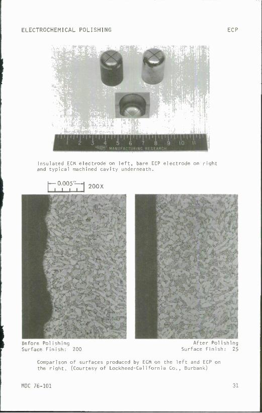
Insulated ECM electrode on left, bare ECP electrode on right and typical machined cavity underneath.
hT»n ™*
Before Polishing Surface Finish: 200
After Polishing Surface Finish: 25
Comparison of surfaces produced by ECM on the left and ECP on the right. (Courtesy of Lockheed-California Co., Burbank)
MDC 76-101 31

ELECTROCHEMICAL TURNING ECT
/
TJTf/^r? / /,
Peripheral i ai e
© m
Brush frv^yfffl stating
u Table
I
Electrochemical turning (ECT) is a special form of electrochemical machining (ECM) to accommodate rotating workpieces. The rotation provides additional accuracy but complicates the equipment with the method of introducing the high currents to the rotating part. Electro- lyte control may also be complicated because rotating seals are needed to properly direct the flow. Otherwise, the parameters and considera- tions of ECM apply equally to the turning mode.
I PRACTICAL APPLICATIONS Roughing of large disk forgings is practical with electrochemical turn- ing. Some shops have plunged a full-face electrode into the face of the rotating disk. Peripheral turning and turning of inside diameters have also been accomplished. ECT can be used to finish parts, such as bearing races, to close tolerances with finishes better than 5 micro- inches AA.
MATERIAL REMOVAL RATES AND TOLERANCES The material removal rates and tolerances for ECT are the same as those obtained with ECM.
AVAILABILITY Equipment is available on special order for both face and peripheral material removal. Capacities range up to 20,000 amperes.
I
32 MDC 76-101

ELECTROCHEMICAL TURNING ECT
Horizontal electrochemical lathe. A 5,000 ampere unit that was still holding 0.0003 inch tolerance after five years of three shifts per day and six day per week operation. (Courtesy of Anocut Inc.)
MDC 76-101 33

ELECTRO-STREAM ES
1&. FeedC
nr Acid Electrolyte 7 Workpiece
Otion Controll—
o£°....o
High Voltage DC Power
Electro-stream™ (ES) is a special version of ECM adapted for drilling very small holes with high voltages and acid electrolytes. The voltages are more than 10 times those employed in ECM or STEM so special provi- sions for containment and protection are required. The feed must be controlled to match exactly the rate of dissolution of the workpiece material. Temperature, pressure, concentration and flow control are needed for the acid electrolyte, which is chosen to be chemically com- patible with the workpiece metallurgical state. For corrosion protec- tion, both the feed and the motion mechanisms are in pressurized chambers, separated from the acid electrolyte. The actual drilling takes place in a plexiglass chamber, suitably vented, with controls for automatic rapid advance of the tool, close programming of feed, dwell at hole breakthrough if desired and rapid retraction prior to indexing to the next location. The tool is a drawn-glass nozzle one or two thou- sandths of an inch smaller than the desired hole size. An electrode inside the nozzle or the manifold assures electrical contact with the acid. Multiple drilling predominates.
PRACTICAL APPLICATIONS Holes ranging from 0.004 to 0.030 inch in diameter with depth-to- diameter ratios up to 50:1 are practical in any conductive material. Holes can be drilled at angles as shallow as 10 degrees. The principal application is the drilling of cooling holes in gas turbines, which are usually fabricated from nickel and cobalt alloys. Insertion of a nozzle with a formed tip permits right-angle drilling deep inside prior holes or cavities. Over 50 holes per machine stroke have been accomplished on multiple parts; automatic indexing provides for the drilling of several hundreds of holes per part.
MATERIAL REMOVAL RATES AND TOLERANCES Penetration rates up to 1 to 2 thousandths of an inch per second are typical for the super alloys. Straightness is about 0.0005 inch per inch and diameter tolerances are about +0.001 or 5% of the diameter. Finishes run from 16 to 63 microinches AA. There is no metallurgical change nor process-induced residual stress in the surface when the proper electrolytes and operating parameters are used.
34 MDC 76-101

ELECTRO-STREAM ES
AVAILABILITY ES is available by license from the General Electric Company, Evendale, Ohio, and they can provide equipment with all the ancillary devices needed to operate the system. The highly corrosive environment can shorten the life of the equipment unless exceptionally good maintenance is rendered. Adjacent equipment must also be protected. Fixturing requires careful material selection to operate in the process envi ronment.
Multiple drilling of cast nickel base alloy with Electro- stream.™ (Courtesy of General Electric Company)
MDC 76-101 35

SHAPED TUBE ELECTROLYTIC MACHINING STEM
Electrolyte
Tube
Heater»
Fixture-'
Shaped tube electrolytic machining (STEM™) is a specialized ECM technique for "drilling" small, deep holes utilizing acid electrolytes. Acid is used so that the dissolved metal will go into the solution instead of forming a sludge as is the case with salt-type electrolytes. The electrode is a carefully straightened, acid-resistant, metal tube. The tube is coated with a film of enamel-type insulation. The acid is pressure fed through the tube and returns via a narrow gap (0.001 to 0.002 inch) between the tube insulation and the hole wall. Feed, constant within plus or minus one percent, advances the electrode into the workpiece at rates (0.040 to 0.140 inches per minute) exactly equal to the rate at which the workpiece material is dissolved. Multiple electrodes, even of varying diameters or shapes, may be used simulta- neously. A guide plate is used to direct the electrodes. A 10 percent solution of sulfuric acid is frequently used as the electrolyte when machining the nickel alloys. The electrolyte is heated to 100 to 120°F and filtered; flow monitors control the pressure. The metal content of the acid electrolyte must be closely monitored. Tooling is frequently made of plastic, ceramics or titanium alloys to withstand the hot acid. The tooling can be shaped to drill odd cross sections and, within the yield limits of the tooling material, divergent holes may be drilled simultaneously. The voltages used are a modest 5 to 15V. The voltage is reversed periodically for a fraction of a second to remove any film buildup on the electrode, but not long enough to remove substantial material that would change the shape.
PRACTICAL APPLICATIONS STEM is used to drill round or shaped holes in difficult-to-machine conductive materials. Holes as deep as 2k inches are practical with length-to-diameter ratios up to 300:1 and diameters ranging from 0.020 to 0.250 inch. Special and oval shapes should have a minimum width of 0.020 inch and a major-to-minor-axis ratio of preferably 3:1. Over 100 holes per machine stroke are practical. The same tooling can produce different sizes of holes within a modest range by adjusting the feed, voltage, and other parameters. A typical case was the simultaneous drilling of sixteen 0.050-inch-diameter holes in cast Udimet 700 nickel
36 MDC 76-101

SHAPED TUBE ELECTROLYTIC MACHINING STEM
alloy. The holes were 9 inches deep in the center of 0.150-inch-thick airfoil walls. The drilling rate was 0.001 inch per second using a 10 percent sulfuric acid electrolyte.
MATERIAL REMOVAL RATES AND TOLERANCES Drilling penetration rates are typically 0.001 inch per second but can range from 0.00075 to 0.0025 inch per second. Several dozen holes have been drilled simultaneously with tooling costs being the practical limit. Runout is typically 0.0015 inch per inch; however, 0.001 inch per inch can be achieved. Diameter tolerance is typically +0.0015 inch. Finishes range from 32 to 125 microinches AA; there is no stress intro- duced into the surface. The electrolyte must be compatible with the metallurgical state of the workpiece to prevent intergranular attack or pitting. The natural radiusing action of ECM eliminates all burrs. Monitoring of current flow during operation provides good quality assurance.
AVAILABILITY The STEM™ process is available by license from the General Electric Company. Their equipment includes controls, tanks, pumps, and so on with enclosures, ventilation and plastic components to protect the operator from the corrosive environment. Corrosion protection is also required for equipment adjacent to STEM™ installations.
Shaped hole "drilling" of nickel alloy with STEM™ process. (Courtesy of General Electric Company)
MDC 76-101 37

1/1
o
o
£3
c/i CÜ o
■a: Li- ce CD
in
c O
*J o
■a o LA c LA -3- 0 O 1 <-) LA
<N 1 1 O LA 1 O LA i i o TJ 1 1 • • O 1 • • i l 4J
L. 1 1 1 1 CM ■— 1 CM CM i i
10 o T> CA CM C up 1 ro 4-» 00 cn
4- 4- O
1/1 1- 41
<u E ro i_
ID LA CA a. CM CA
1 (A CM CO CA -T CO i CA-* i i O 0 1 1 • • O i ■ • i i 4->
u i i 1 1 — o 1 o o i
0 M) u oo + a.
CM
ro U
a. >- i-
I. 4) >- ro _l
in
0) 4-» 4-1 ,—, u in ra CM c ro O ro o i/i
3 a. L. 41 41 — V t/> CH 3 .o c
fi in 3 o i_ ro 41 in ^ 4J o >
-C i_ .* < 0 4J
u .—* .o O U L. ro c o a) ro — o_ E fvl jt
■— a. o +- L- *—" i~ < o 0 U O zu o L. TJ 0 -* in u. -Q o C HI C L. o *-> in TJ
o E o o "» ro — c 4) C =* z — i_ .- ro c 4-i a. ro C ID
4-1 o 4-1 X. O 4J L- O £ 41 1 ID 4- co in ._ < . h- N ; 1.
E 41 L. i_ in 4-> .C 3 4} 4-« U Q mom ro L- o >— T) E 4J CTI C o 4-> L. N ro 4-1 ro 4) o ro
■M C 41 4- >- .— in 4J .- — 4) o 4J L- L- u ID 3 41 — < _* CO — 3 •— o u- 41 41 or cr O — O — C 4) cn 4) a
4- a> IS in ro ^ ro ro > L- 4- 41 E M- 41 l_ O O in i- ro 4J 1- 3 4- cn 4) LU Cn U- 41 O 3 in cn 4-i ■— < C 4J
10 4-» 4-» COT) >• L- O 1 ro 4- u 1/1 oi in ■D L - L- 41 41 ro 4-1 SI E 0 0) in ro ro l- U in O 4-1 — +j ro o o
> <u . . ro — m 41 C 41 u 41 o 4) < -i a. a_ x z: c£ CC — CO X X »e L- D- >-
1-
in in 41 c X Ol 3 * ro
u
41 3 cn 4-1 ro
14.
o <— — 41 ac ro Ol
o .— L- i— U u •— TJ CO 3 T> ro >- u C 4) — 41 — CJ ro CO 1- 1- CO •— U 1_ in ^-^
u- -c a) <u o CO U 41 a) JZ U- L. U *J 4-> C 4-1 4-1 4-1 c cn o 3 a> — ro o 41 — ro 0 — T.
CO a: < s: M n < s: r-M X
■o -C 0 l_ '-! — L_ ro 4- 0
-C -C c c -— s 01 — cn E
10 in -C L. 01 01 4- O 4- c O) — T3 c ■o L- 01 c -C irj l_ ro 4-
-C 4- 01
x: s
ro in — 0) c w. L. 1 o 01 — o +- in
1 c 01 4-
o 01 Q-
01 ID
-X 01 ■— 4- CD D o o cn
JO « c Zl
_i
4- O 0 c 0 ~ cn
o L D +- 0 01
c in ■o
• 0) — 01 01 CD — in L in O ID ^ +- 10 ID > 01 a 4- •— o
o l_ 3 IN s 01 0) 3 CT o L. +- m <i> c ro u ro a> CD L. JZ E 01 o. ^ o 4- 0 0) X 4- ~ 1_ 3
ill
+- 01
o c Ul in
4-
ID " ID +- -i- <r 0) TJ > cn TJ o — 0) cn
c — in 4- CD CD +- ID +- in ID «1 t_ C L. E c c L. CD 4- 01 O L- — •— 01 ^ cn
■— 0 0 ro cz t- u in c a. E 01 — 0) OJ Ol ro M- o «CM L • 3 M— c ^ + >- OlTl 3 01 Ü TJ c — l/l L_ c c ^^ c; 4- — 1/1 C L. — ID in ro c -c CD
■ — Zl JC 4- 01 cn c_ O c: 4- c in u
L Ü 10 01 1 cr — CD O o in 41 O >
4- cn 0 L Q_ — 0 0 0 CD i- " 4- O CO c c — ^ 01 L. cn
in in -Q 01 4- CD Ul in .c in ro L O L- CD 01 +- <D 0) in ro 01 o. +- 4- TJ E e in — E ro 10 c O 0) Ol CD 0 u u ID O in L c u
m CD in 4- >» ■o ~o 3 .o 0) 01 4- — ai c c o c 01 — c — — ^ cn TJ — 01 10 —
4- cn U ro 4- C V 0) 01 CD 10 3 0 C
c c -C TJ U- — 10 -Q n — TJ 0 — O 01 -C ID ro i_ u in X 10 c +- 4- cn ID u 0) O CD
JZ .c i_ E u 01 01 4- E O 0 4- -C x: CL CD Ol L- 3 +- t- CD C Q. l_ 4- C- X)
TJ CD 0 01 0 C C jr 3 -c: 01 TJ — — TJ 3 C S 01 Ol CD
CD sH 3 C C -^ > 4- 4- c 1 L. c E c ro JC 10 ro 1 CD — :i — > 1/1 4- — 1 cn 0 u 0 — CD
JD J3 Q.4- CL — L_ o L. X. o < < o TJ o 4?8 Q.4- E 4- 01 4- 0 D 4- (0 -Q CD E ^ U j= 01 "O C 4"
— 4- 0) 4- L- C — C 0) X Q. > Q. Ol ID IZ 3 +- ro CD c 01 X ^ g 0 S Q 0 Q in = z * 4- u «n — =* E 10
38 MDC 76-101

THERMAL NONTRADITIONAL MACHINING
? Very few of the thermal material removal processes use the term thermal in their name! Laser, discharge, plasma, or beam are typical of the descriptions used. Upon analysis, however, all use high temperatures to melt or vaporize material from the workpiece. The principal energy mode is thermal with the electrical discharge, light beam or electron beam acting as the source of concentrated heat.
Thermal Nontraditional Machining Processes
EBM - Electron Beam Machining EDG - Electrical Discharge Grinding EDM - Electrical Discharge Machining EDS - Electrical Discharge Sawing EDWC - Electrical Discharge Wire Cutting LBM - Laser Beam Machining LBT - Laser Beam Torch P8M - Plasma Beam Machining
Electrical discharge machining is the oldest of the nontraditional material removal processes. It had its first real production activity during World War II when it was used to shape workpieces from war generated high strength materials. It has come a long way from the original sparking "tap buster". EDM machines are so well developed and used in so many ways that the process is an "old friend" to the extent that many now consider it to be a conventional process. The application of computer numerical control, tracing heads and electronic controls to manipulate the discharge keeps EDM in the forefront of the commercially usable NTM processes.
The laser, electron beam and plasma beam machining techniques all make use of the ease and versatility of electricity to control these basi- cally thermal material removal processes. This ease of control also provides opportunities for adaptive control, automation and integration into transfer line systems.
The surface integrity effects resulting from the thermal NTM processes are summarized in Table V, p. 56.
MDC 76-101 39

ELECTRON BEAM MACHINING EBM
Cathode Grid
"• High Voltage Cable
Electron Beam Gun
Viewing J, Port Vacuum Chamber
Work Table |~
&TTk*J f\ Workpiece
n it B a» h High Vacuum Pump
Electron beam machining (EBM) removes material by melting and vaporizing the workpiece at the point of impingement of a focused stream of high- velocity electrons. To eliminate scattering of the beam of electrons by contact with gas molecules, the work is done in a high-vacuum chamber* (10"5 to 10"° mm of mercury). Electrons emanate from a triode electron beam gun and are accelerated to 3M the speed of light by the 50 to 150 kilovolts at the anode. Magnetic lenses focus the electron beam on the workpiece where a 0.001-inch-diameter spot can attain an energy density of up to 10° watts per square inch to melt and vaporize any material. The short bursts of the beam limit the extent of the heat-affected zone; however, there is always a layer of recast material or heat-affected material on the cut surface. View ports and optical tracking systems help guide the beam or workpiece. Deflection coils permit magnetic control and programming of the beam to any desired pattern over a small area — about IM inch. Various patterns can be programmed into the deflection-and-beam-pulsing type of system utilizing computers and "flying spot" scanners to generate a wide variety of results. Shielding of the secondary radiation is necessary for safety.
PRACTICAL APPLICATIONS Micromachining of thin materials and hole drilling are t applications for EBM. Depth-to-diameter ratio can reach multiple pulses. The capability for machining microhol slots with high precision in a short time in any materia designs. The absence of mechanical contact and the s automatic control enhance the process but the necessi vacuum lengthens the floor-to-floor cycle time. One app 400,000 holes 80 microinches in diameter in each square inch-thick foil. Another application incorporates the d approximately 0.020 inch in diameter in 0.250-inch mater several times faster than EDM or ECM. Metering orifices dies and spinnerette holes are other applications.
he two principal 100:1 with
es and narrow 1 permits unique uitabi1i ty for ty to work in a licat ion places inch of a 0.001- ri11ing of holes ial at speeds , rough wi re
40 MDC 76-101
ELECTRON BEAM MACHINING EBM
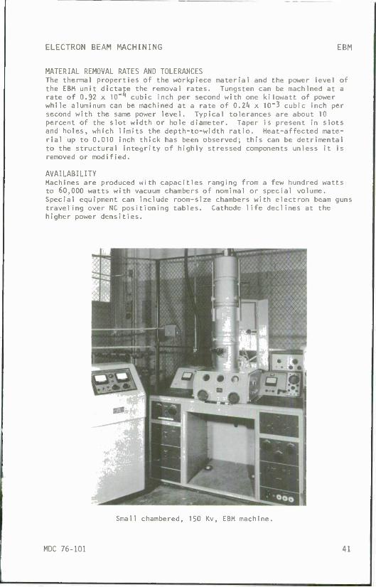
MATERIAL REMOVAL RATES AND TOLERANCES The thermal properties of the workpiece material and the power level of the EBM unit dictate the removal rates. Tungsten can be machined at a rate of 0.92 x 10"^ cubic inch per second with one kilowatt of power while aluminum can be machined at a rate of 0.24 x 10~3 cubic inch per second with the same power level. Typical tolerances are about 10 percent of the slot width or hole diameter. Taper is present in slots and holes, which limits the depth-to-width ratio. Heat-affected mate- rial up to 0.010 inch thick has been observed; this can be detrimental to the structural integrity of highly stressed components unless it is removed or modified.
AVAILABILITY Machines are produced with capacities ranging from a few hundred watts to 60,000 watts with vacuum chambers of nominal or special volume. Special equipment can include room-size chambers with electron beam guns traveling over NC positioning tables. Cathode life declines at the higher power densities.
Small chambered, 150 Kv, EBM machine.
MDC 76-101 41

ELECTRICAL DISCHARGE GRINDING EDG
Electrical discharge grinding (EDG) is the removal of a conductive material by rapid repetitive spark discharges between a rotating tool and the workpiece, which are separated by a flowing dielectric fluid. The spark gap is servo controlled with a setting between 0.0005 and 0.003 inch. The d-c power source has capabilities ranging from 30 to 100 volts, 1/2 to 200 amperes and 2 to 500 kilohertz. The conductive wheel, usually graphite, rotates at 100 to 600 sfpm in a dielectric bath of filtered hydrocarbon oil. The insulated wheel and work table are connected to the d-c pulse generator with positive on the wor.kpiece being "standard". Higher currents produce faster cutting, rougher finishes and deeper heat-affected zones in the workpiece. Wheel wear ranges from 100:1 to 0.1:1 with an average of 3:1, depending upon current density, work material, wheel material, dielectric and sharpness of corner details.
PRACTICAL APPLICATIONS Greater accuracy in cutting hard materials such as form tools or tung- sten carbide throwaway bits is possible with EDG even though its cutting rates are low. Lamination die grinding in the hardened state is a frequent use of EDG. The absence of significant cutting forces permits grinding fragile shapes in any conductive material.
MATERIAL REMOVAL RATES AND TOLERANCES Material removal rates range from 0.01 to 0.15 cubic inch per hour with the higher figures accompanied by finishes in the 63" to 125-microinch AA range. Corner radius is dependent upon overcut values used and ranges from 0.0005 to 0.005 inch. Tolerances to +0.0002 inch are normal with +O.OOOO50 inch achievable. Finishes improve with an increase of spark frequency and are typically 16 to 32 microinches AA. The melting, vaporizing and resolidification of the surface of the workpiece leaves a heat-affected zone that can be from a few ten thousandths to a few thousandths of an inch deep. Hardness alterations occur which also affect the material properties. Highly stressed applications should
42 MDC 76-101

ELECTRICAL DISCHARGE GRINDING EDG
have these affected layers removed or modified to insure the best surface integrity of the component.
AVAILABILITY Equipment is regularly available in a wide range of sizes for EDG.
<mM a
.*-"*&%
• • • »»#
I
■ ** •
• •
Wheel and fixture for EDG of residual stress specimens. Dielectric tank was drained for picture.
MDC 76-101 43

ELECTRICAL DISCHARGE MACHINING EDM
ServO'Controlled Feed
1 Toolholder
Electrical discharge machining (EDM) removes electrically conductive material with rapid repetitive spark discharges from a pulsating d-c power supply with a dielectric flowing between the workpiece and the tool. The shaped tool (electrode) is fed into the workpiece under servo control until a spark discharge breaks down the dielectric fluid. The frequency (200 to 500,000 sparks per second) and energy per spark are set and controlled with a d-c power source. The servo control maintains a constant gap between the tool and the workpiece while advancing the electrode. The dielectric oil flushes out the vaporized and condensed material while reestablishing insulation in the gap. Surface finish improves with increased frequency and reduced current. Material removal rate, surface roughness and overcut all increase with a current increase or with a frequency decrease (or longer "on" time cycles). Electrode materials frequently used are brass, copper, copper tungsten, tungsten wire and graphite. Spark gaps range from 0.0005 to 0.020 inch with closer tolerance control and slower cutting rates associated with the smaller gaps. Erosion occurs on the tool as well as the workpiece with wear ratios ranging from 0.5:1 to 100:1, depending on spark wave-shape from the power source, electrode material and workpiece material. A nearly "no wear" combination of operating parameters can be found for electrical discharge machining steel when using reverse polarity, as opposed to "standard" polarity (positive on the workpiece).
PRACTICAL APPLICATIONS EDM cuts any electrically conductive material regardless of its hardness and is particularly adapted for machining small irregular slots or cavities. Because of the absence of physical contact, delicate struc- tures can be cut successfully. Cutting is three-dimensional as the shaped electrode is fed into the workpiece. Because the sparks focus first on peaks and corners, burr-free cutting occurs. Multiple electrode, automatic dressing, automatic positioners and NC motion control all contribute to electrical discharge machining's versatility. Tool and die work is frequent but mass production and even transfer line applica- tions exist. Small and/or shaped holes at shallow angles to the work- piece surface are commonplace. A recast and heat-affected layer occurs
44 MDC 76-101
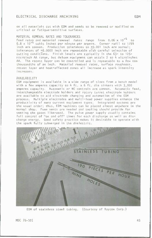
ELECTRICAL DISCHARGE MACHINING EDM
on all materials cut with EDM and needs to be removed or modified on critical or fatigue-sensitive surfaces.
MATERIAL REMOVAL RATES AND TOLERANCES Feed rates and material removal rates range from 0.06 x 10 to 6.6 x 10"^ cubic inches per minute per ampere. Corner radii to 1/61» inch are common. Production tolerances to +0.001 inch are normal; tolerances of +0.0002 inch are repeatable with careful selection of cutting conditions. Finish levels are typically in the 63- to 125- microinch AA range, but deluxe equipment can attain 2 to !( microinches AA. The recast layer can be controlled and is repeatable to a few ten thousandths of an inch. Material removal rates, surface roughness, recast layer and heat-affected zones all increase as spark intensity increases.
AVAILABILITY EDM equipment is available in a wide range of sizes from a bench model with a few amperes capacity to k ft. x 6 ft. die sinkers with 3,000 amperes capacity. Automatic or NC controls are common. Automatic feed, interchangeable electrode holders and rotary turret electrode holders are available to aid electrode changing and automation of the EDM process. Multiple electrodes and multi-lead power supplies enhance the productivity of many current equipment types. Integrated systems are the usual order; thus, EDM machines can be placed almost anywhere in the normal shop. Fume vents are needed and tooling should provide for venting the gases liberated. The pulse power supply usually contains full control of "on and off" times for each discharge as well as dis- charge energy. Good safety practice makes it desirable to operate with the spark fully submerged in the dielectric.
EDM of stainless steel tubing. (Courtesy of Raycon Corp.)
MDC 76-101 45

ELECTRICAL DISCHARGE SAWING EDS
Electrical discharge sawing (EDS) is a variation of electrical discharge machining that combines the motion of the band saw with electrical erosion of the workpiece. The rapidly moving (5000 to 6000 fpm) 0.025- inch-thick, special-steel, knife-edge band is guided into the workpiece by carbide-faced inserts. A 1/32-inch kerf is formed but no controlled gap is maintained between the saw blade and the workpiece as in EDM. No dielectric is used; therefore, there is continuous arcing from the low- voltage (6 to 2'tV) , high-current power source. Water flow quenches the arc and cools the workpiece. While the work is power fed into the cutting band, neither the band nor the work is subjected to major forces, so fixturing can be minimal. Precise adjustment of the feed rate must be made to be in exact balance with the arc erosion rate.
PRACTICAL APPLICATIONS Fragile cellular structures can be cut from aluminum, stainless steel or titanium honeycomb. Thin-walled heat exchanger tubular assemblies can be cut. No-burr cutting produces little or no roll-over of edges on thin materials. Cuts up to ^0 inches deep have been made. Only electri- cally conductive materials can be cut with EDS.
MATERIAL REMOVAL RATES AND TOLERANCES Cutting rates range from 5 to 200 square inches per minute. Flatness ranges from +0.003 inch TIR at the lower feed rates to +0.016 inch TIR at the maximum cutting rates. The finish is an electrically etched surface; however, the arcing leaves a recast and heat-affected zone below the surface.
AVAILABILITY EDS machines are regularly available with throats up to kB inches deep for 26-inch workpieces.
46 MDC 76-101

TT—T
ELECTRICAL DISCHARGE SAWING EDS
EDS of copper-tube heat exchanger at 50 square inches per minute. (Courtesy of DoAl1 Company)
MDC 76-101 47

ELECTRICAL DISCHARGE WIRE CUTTING EDWC
Dielectric Supply
Programmed
Numerical i:y Control
Wire Guides IT»,
Electrical discharge wire cutting (EDWC) is a special form of electrical discharge machining wherein the electrode is a continuously moving conductive wire. It is often called traveling-wire EDM. The tensioned copper or brass wire of small diameter, 0.002 to 0.010 inch, is guided to produce a straight, narrow-kerf cut. Usually a programmed or numer- ically controlled motion guides the cutting while the width of kerf is maintained by the discharge controls. The dielectric is oil or deionized water carried into the gap by motion of the wire. The wire is inexpensive enough to be used only once.
PRACTICAL APPLICATIONS The straight cut perpendicular to the major axis of the workpiece has no flaring or bell mouth and extremely tight corners can be cut with almost no radius. Punches, dies and stripper plates can be cut in any of the hardened conductive tool materials. The same NC tape can be used repeatedly for short production runs. Mirror-image profile work and internal contours from a starting hole are frequent. Stacking of sheets for multiple cutting is possible.
MATERIAL REMOVAL RATES AND TOLERANCES Cutting of 0.001- to 3"inch-thick materials can be done at a rate of 1 square inch per hour, which on thin parts can yield cutting at ^l inches per minute. Positioning accuracy to +0.0002 inch is normal in all metals.
AVAILABILITY Several manufacturers regularly build EDWC equipment with NC, tracer controls and all programming accessories. Die relief, angle generators and offset controls are available on most machines along with kerf-width control via the gap setting and wire-diameter selection. Equipment is also available with cam or other mechanical programming for the wire motion as well as with standard EDM servo control for straight cutting.
48 MDC 76-101

ELECTRICAL DISCHARGE WIRE CUTTING EDWC
Numerically controlled EDWC machine. (Courtesy of Charmilles Corp.)
MDC 76-101 49

LASER BEAM MACHINING LBM
1 Flash Lamps
Focal J Length H
Total Reflecting
Mirror
Laser beam machining (LBM) removes material by melting and vaporizing the workpiece at the point of impingement of a highly focused beam of coherent monochromatic light. Laser is an acronym for "Jjght amplifi- cation by stimulated emission of radiation." The electromagnetic radiation operates at wavelengths from 0.3 to 300 microns. The most common wavelengths for material removal using solid state lasers are 0.69 micron for ruby, 1.06 for neodynium glass (Nd:Glass), 1.06 for neodymium yttrium aluminum garnet (Nd:YAG), and 10.6 for carbon dioxide gas laser. Of these four, only the 0.69 micron radiation of the ruby is in the visible light range. The Nd:Glass and Nd:YAG wavelengths are in the near infrared and the CO2 wavelength is in the far infrared range. The optical characteristics of the workpiece determine which wavelength should be used.
Most of the solid state lasers operate only in a pulsed mode with greater than 10 pulses per second repetition rate common with adequate cooling systems. An exception to this is the Nd:YAG laser, which like the C02 laser, can be operated either pulsed or in a continuous wave to produce a continuous power output.
For pulsed operation of solid state lasers, the power supply produces a short intense pulse into the flash lamps which concentrate their light flux on the lasing material. The resulting energy from the excited atom is released at a constant frequency. The monochromatic light is ampli- fied by successive reflections from the mirrors. The thoroughly collimated light exits through the partially reflecting mirror to the lens, which focuses it on or just below the surface of the workpiece. The small beam divergence, high peak power and single frequency provide excellent smal1-diameter spots of light with up to 3 x 10¹⁰ watts per square inch of power that can sublime almost any material.
During laser beam machining, the expulsed material solidifies to a dust; therefore, a cleaning system is needed in addition to protection for the lens from the molten particles. Adequate eye protection is needed for both direct and reflected laser light.
50 MDC 76-101

LASER BEAM MACHINING LBM
PRACTICAL APPLICATIONS Small precision cuts or holes in thin materials can be produced by LBM. Scribing of ceramics can be done since there is no massive heat shock or mechanical contact or large forces between the tool and workpiece. LBM is not a mass material removal process; however, its operation in air at rapid repetitive rates and its ease of electrical control commend it for mass micromachining production. Multiple pulses permit hole drilling up to 50:1 depth-to-diameter ratios on 0.005-inch-diameter holes while 0.050-inch-diameter holes can be drilled through 0.100-inch-thick mate- rial. Shallow angles (15 degrees) to the surface can be drilled. Other applications include engraving, resistor trimming, sheet metal trimming and blanking. The same equipment can be used to weld, surface heat treat or machine, which makes the laser a "universal" machine tool.
MATERIAL REMOVAL RATES AND TOLERANCES Removal rate is slow, k x 10"^ cubic inch per hour; however, 0.020- inch-diameter holes can be drilled in milliseconds with accuracies to +0.001 inch in thin stock of tungsten, brass or ceramics. The hole walls will be irregular and tapered as well as having a recast structure from the heat-affected surface. Repeatability is good and yields can be improved over conventional micromachining processes. The heat-affected zones with a hardened recast layer are typical of laser machined sur- faces. This recast layer can be detrimental to material properties and should be removed or modified on applications where high stresses or fatigue life is a concern.
AVAILABILITY Several sources of laser components or systems exist. The principal equipment concern is workpiece positioning and control. Integration of an NC table with focus, beam intensity or standoff distance is common. Safety interlocked enclosures are commonly used. Bench-top equipment with a few watts capacity to computer controlled systems of several kilowatts capacity are commercially available.
Surgical needle (0.013 inch diameter) with laser drilled O.OO6- inch-diameter hole, 0.060 inch deep. (Courtesy of Holobeam Laser Inc.)
MDC 76-101 51

LASER BEAM TORCH LBT
Laser l£ Gas inlet :
Lens
1 I Orifice
Table p
Motion L
Wofkpiece F7ffl7a ,
Laser beam torch (LBT) is a material removal process that utilizes the simultaneous focusing of a laser beam and a gas stream on the workpiece. A continuous-beam laser is focused on or slightly below the surface of the workpiece and the absorbed energy causes localized melting. The oxygen gas stream promotes the reaction as well as purges the molten material from the cut. Argon or nitrogen gas is used to purge the molten material and protect the workpiece when organic or ceramic materials are being cut.
PRACTICAL APPLICATIONS The carbide nozzle and the laser's focal point must be kept at a fixed distance from the workpiece for uniform cutting. A height-sensor con- trol is available to hold this standoff distance within +0.005-inch tolerance. The cut is characterized by a narrow kerf and a narrow heat- affected zone. The width and quality of cut depend on cutting speed, laser power, standoff distance, nozzle diameter, type of gas and laser focal distance. Numerically controlled or mechanically guided cuts can be made in most materials. Plywood die-board slotting for steel-rule dies, titanium plates for airplanes, stacks of cloth for suits and ceramic workpieces have been cut in regular production. The low level of distortion, narrow kerf and smooth workpiece edges are advantages. Most LBT cutting is done on 0.050- to 0.100-inch-thick sheet material; however, 0.50-inch-thick carbon steel has been cut at 30 inches per minute with high-power lasers. Taper is present in most cuts. Trimming and post-cutting cleanup operations are minimal.
MATERIAL REMOVAL RATES AND TOLERANCES The cutting rates depend on material thickness but can range from 30 inches per minute on 1/16-inch-thick tool steel to 250 inches per minute on 0.020-inch tinplate to 500 inches per minute on 0.030-inch-thick Lexan with a 1/2-kW laser. Accuracies to +0.004 inch are obtained with heat-affected zones ranging from 0.002 to 0.010 inch wide and kerf being
52 MDC 76-101

LASER BEAM TORCH LBT
0.001» to 0.030 inch wide with a 1/2-kW laser. A 1/2-kW, continuous- wave, carbon-dioxide-gas laser can cut 1/4-inch-thick aluminum at 3 inches per minute or iM-inch-thick titanium at 1^0 inches per minute.
AVAILABILITY A wide assortment of machine shapes and controls is available with power capacities ranging from fractional kW to 15 kW. Many units employ NC for control of the cutting path.
WESTCOTT 8h -*■ RULER
.40 THICKNESS KERF AT TOP KERF AT BOTTOM FEED, IN/MIN.
.25
.0 2 4
.03 5 107
Slicing of titanium 6A1-4V with LBT. (Courtesy of The Boeing Co.)
MDC 76-101 53

PLASMA BEAM MACHINING PBM
Outer Shell
Water Cooled Tungsten Electrode
Plasma beam machining (PBM) removes material by utilizing a superheated stream of electrically ionized gas. The 20,000 to 50,000°F plasma is created inside a water-cooled nozzle by electrically ionizing a suitable gas such as nitrogen, hydrogen, argon, compressed air, or mixtures of these gases. Since the process does not rely on the heat of combustion between the gas and the workpiece material, it can be used on almost any conductive metal. The plasma —a mixture of free electrons, positively charged ions and neutral atoms — is initiated in a confined gas-filled chamber by a high-frequency spark. The high-voltage d-c power sustains the arc, which exits from the nozzle at near sonic velocity. Water injection is sometimes used to assist in confining the arc, blasting away the scale and reducing smoke. Greater nozzle life is also claimed for water-injection-type torches. Control of the nozzle standoff dis- tance (lA to 5/8 inch) from the workpiece is important. One electrode size can be used to machine a wide range of materials and thicknesses by suitable adjustments to the power level, gas type, gas flow rate, traverse speed and flame angle. PBM is sometimes called plasma arc machining (PAM) or plasma arc cutting (PAC).
PRACTICAL APPLICATIONS Profile cutting of metals, particularly stainless steel and aluminum, has been the most prominent commercial application; however, mild steel, alloy steel, titanium, bronze and most metals can be cut cleanly and rapidly. Multiple-torch cuts on programmed or tracer controlled cutting tables on plates up to 8 inches thick in mild steel are possible. Smoothness of cut with freedom from contaminants is an advantage. Well- attached dross on the underside of the cut can be a problem. Eye shield- ing and noise protection are necessary for the operator and those in nearby areas.
54 MDC 76-101

PLASMA BEAM MACHINING PBM
MATERIAL REMOVAL RATES AND TOLERANCES One-inch-thick aluminum plate can be cut at 30 inches per minute while lA-inch carbon steel can be cut at 160 inches per minute. The use of water injection can increase the carbon steel cutting rates to 20 fpm for 3/l6-inch-thick plate. The taper on the sides of the cut ranges from 5 to 10 degrees and the kerf width is usually 3/32 to 3/8 inch. Corner radius is a minimum of 5/32 inch on thinner plates. Tolerances for slots and holes ordinarily range from +1/32 inch on 1/4- to 1-3/8- inch-thick plates up to +1/8 inch on 6- to 8-inch-thick plates. A heat- affected zone can range from 1/32 to 3/16 inch wide, depending on work- piece material, and depth and speed of cut. Sometimes an increase in hardness will accompany the heat-affected zone and require more time for edge-finishing operations. In many cases the cut edges may be adequate for the application.
AVAILABILITY Programmed motion of many types from NC punched cards to optical follow- ers is available with multiple-torch capability and cutting tables up to kk feet x 82 feet. Cutting speeds range from 2 to 2^0 inches per minute.
Plasma Beam Machining of plate. (Courtesy of Thermal Dynamics Corporation)
MDC 76-101 55

o
<: o
I—I en
< o
-1 <
«I Di
<_J ■a:
in c 0 o 4J o — o -o c o v*> -d- 0 o • vO o LA
i i O 0 0 1 1 O 1
-o 1 1 i i 1 1 1 O u 1 1 oo h-. CA 1 1 La (0 LA O
X» CM OO c ^ J- (0 CM 1 4-» CA t/>
4- 4- O
i/> u CD 4-)
£ e O (0
f0 LA CM
a. LA CM en
<n 1 i/i i t •— LA O 1 1 sO a> 1 1 i i 1 1 0 o i i •— O CM 1 1 O 4-1
0 CM L> c-\ r^ a.
CM T" (0 o
a >■
l—
L-
<D s 03
—1 W 0) *~> 4->
-—s 0 in (0 Oj c 0} a ro u in
3 Q. 1_ a) 0) '—* a> L0 oc 3 _0 c
(A i/i 3 O u A3 a) 01 ,—N 4J — 0 >
sz L. _* < 0 4V a --* X U CJ L. ro ^-s ~ c O <U 4> — 0. E M J*
Q. O u L_ < 8 o — -H 0 «t O x L. -o 0 -* (ft 4_ -»-^ X O C <D C L. O 4J (A XI .— 0 E O U un CO — C <U C 3*fc X .— i_ .— CO C 4-> Q. (0 c CO
4-1 O *-» X O 4-1 I- 0 -c <u 1 (0 4- 15 (/) ._ < * 1- IVI z 1-
E 0) L L- <A 4J X 3 0) 4-1 U Q 0) 0 0) to 1- 0 — Xf E 4J en c 0 *-» L_ N CO 4J CD QJ O CO
4-J C 0) 4- >- — (/) 4-* — .— 4) O 4J L- L. u ID 3 0) — < -* i/> — 3 .- 0 4- 0) 0) oc cr £3 — 0 — C <U en a> Q.
4- a) CD (/) co — CO f0 > L. 4- a> E 4- 0) L- o u m l- ro 4J 1_ .— 3 4- CT) a> ÜJ CT> u_ ._ .- <u 0 3 Ul Ol 4-1 ^ < C 4-J
0) 4-» 4J C 0 T3 >• L- O (0 4- u tn tn W XJ 1_ — !_ <U CD CO 4J -C E O a) w ru «J L- U (/) U 4-1 — 4-» fD O O
> 0) .— — nj — (U a> c a) 01 0) O aj < -i Q_ Q- X X C£L a: — <•> a: x <*«? 1- Q, >- 1-
in Ul 0) c X at 3
* u
0) 3 CT> ro
Li_
O 1— - — V C£L 11 01
1- — U V •- -o 0J 3 XJ <D >* u C 0) — _ 0) — O CO (DLL. (/) 1— 1- i_ in ^—N
4- x a) a) 0) 15 1) 1) 0) JZ u_ 1_ O 4J 4-» c 4-t 4-" 4-J c cno 3 0) — ro 0 0) — f0 O — x in x < s: M X < X fsl x ■—'
o —
L_ 0) c: sz 1) L (0 +■ X
in ^1
J£
fD ul a' c VI
L_ 3) O CD E O 4- in .—
ICJ a U E 0)
4- a) 01
to JC 01 — M- 0 J O TJ I/) X
■ss. _1
4- O 0 c 0 1_
01 0
-—- L. 3 4- O 01 C 01 X) • CD — 0 0)
0) en L 01 j ro j^ 4- ro fD > 01 4D
-J- •— O "O L_ 3 CN S 01 (1) 3 cr O U 4- tf) CD c ro U rt3 0) CD L 4= E 01 a. C O 4- O a> X 4- c n
ID a) yi v4-
-t- O CJ 1 01 HI ~< ID +- 4- IX a) TD > in n 0 a> 1/1
c — 01 4- 0) 0) +- ■-; +■ </t 1U 01 1- c L. E c c L 0) +- 0) O L_ ■ — 01 J: 01 ._ 0 O m c 1- u V) c 0. E 0 .— 0) 0) en ro
O ^1
L - rj ^+- c JZ + 1 >. aiTD 3 0) 0 Ü — c — 01 L C c ^ C 4- .— 0) c L_ •— ro 01 to C £ <u
3 X 4- 01 01 l_ O c 4- cr in =3
L_ O fD 1 a> cr — <D O O 01 E 0) 0 >
01 CJ 0 L a.— O O O CD L. u M- 0 01 c C 3 a> i_ in
01 Ul a 0) +- <D [/I ul JZ 01 n L O 1- CD 0) 4- CD 0 Ul 01 a) Q. +- 4- XI £ E i/i — E ro (0 c 0 0) Cl ai 0 u 0 a: u (/i L- c 0 — ■ — in CD a) 4- —
>■
T5 XI 3 X <D tfl 4- — en c c 0 c 01 — c .— — -C O) ■0 — (D 10 —
4- 01 t_ (0 +• c 0 a; a> CD <a 3 O c
C c ^r T3 Li, — 10 XI J3 — XJ O CJ in -c 10 ro L L. 01 I 10 c: 4- +- l/l ro u 1) 0 0)
JC X L E O OJ CD +- E ) 0 +-
JZ x: CL CD d> i- 3 4- 4- 0) U CL L. l_ J3
XI Q) O O O c: c X O JZ 01 "O ..._ .— T3 £ c 5: 01 cn 01
CD >^ 3 c c j^ > +- 4- — c 1 !_ cz E c ro ^ (0 ra 1 CD — ' > 01 4- — 1 if) 0 L O .- 0) -O xi
O Q_ **" a.
il !k — (_ O < < O "a 0 4? 8 Q.M-
£ 4- 0) +- 0 ZJ 4- <g 4D 0 E X L _^ 0) "U C +- — 4- 0) 4- l- c — C
(D X CL > CL en fO ^Z 3 +- ~ <D c 0) X U Q O
.... a O Q 01 r (0 t
Z * +- u — =fc E CO
56 MDC 76-101

CHEMICAL NONTRADITIONAL MACHINING
Chemical nontraditional machining is characterized by an absence of stress induced into the workpiece as a result of the processing. This is beneficial where thin or delicate parts are to be machined or where distortion should be minimized. Matching of the workpiece material with the cutting chemicals must be exact to secure the best results. Equally exacting is the necessity to provide a continuously fresh supply of chemicals to the surface being cut and to provide for the proper disposal of the spent solutions.
All four of the of the chemical nontraditional machining processes use the chemical reaction as the principal means for removing material from the workpiece; however, it is sometimes enhanced by adding various forms of electrical or thermal energy.
Chemical Nontraditional Machining Processes
CHM - Chemical Machining ELP - Electropolish PCM - Photochemical Machining TCM - Thermochemical Machining
The surface integrity effects resulting from the chemical NTM processes are summarized in Table VI, p. 66.
MDC 76-101 57

CHEMICAL MACHINING CHM
Mask
Chemical Reagent
Hanger
(530323- Heating
Cooling
Chemical machining (CHM) is the controlled dissolution of workpiece material by contact with a strong chemical reagent. The thoroughly cleaned workpiece is covered with a strippable, chemically resistant mask. Areas where chemical action is desired are outlined with the use of a template and the mask is stripped from these areas. The workpiece is then submerged in the chemical reagent to remove material at an equal rate from all exposed areas. The solution should be stirred or the workpiece agitated for more effective and more uniform action. Increas- ing the temperatures to 100 to 200°F will also expedite the action. The workpiece is then washed and rinsed and the remaining mask is removed. Multiple parts can be machined simultaneously in the same tank.
Contour machining is accomplished by successively stripping masks and resubmerging the workpiece in the chemical bath. Etching of the work- piece proceeds radially from the openings in the mask which results in an undercut as well as a depth of cut. The ratio of distance etched beneath the mask to the distance etched into the workpiece (the etching factor) is typically 1:1 but it can be up to 1:3. A controlled rate of immersion or withdrawal from the bath will produce tapered sections. The workpiece should preferably be oriented so that the grain is in the direction of the longest cut.
The chemicals are very corrosive and must be handled with adequate safety precautions; both vapors and effluents need suitable environ- mental handling.
PRACTICAL APPLICATIONS Nearly all materials can be chemically machined; however, the depth of cut has a practical limit of 1/4 to 1/2 inch. Large shallow areas are especially suitable for CHM since removal is uniform and simultaneous. No burrs are produced and no workpiece surface stresses are generated by CHM. Short-run, quick-change, low-cost tooling offers process flexi- bility. Thin sheets, formed sheets and delicate cuts are particularly suitable for CHM with a maximum practical thickness for blanking of 1/16 inch. Sharp radii cannot be produced in the cutting direction.
58 MDC 76-101

CHEMICAL MACHINING CHM
Workpiece size is limited only by tank dimensions; aluminum wing spars have been chemically machined in 3' x 8' x 50' tanks. Surface contours, scratches and waviness will be reproduced as CHM proceeds. Porous castings are poor candidates for CHM while welds or welded areas are difficult to cut uniformly.
MATERIAL REMOVAL RATES AND TOLERANCES The typical material removal rate is slow; about 0.001 to 0.002 inch per minute but it can be as low as 0.00025 ipm on the more resistant materials.
Uniformity of removal rates is dependent upon the chemical and metallurgical uniformity of the workpiece. A violent or directional fluid agitation can lead to uneven cut time. With good time, tempera- ture, and solution control, accuracies to +0.0005 inch can be achieved on shallow depths of cut. Deep cuts yield tolerances up to +0.005 inch. Minimum width of cuts or lands between cuts should be twice the depth of cut plus the etch factor.
Scribe and peel masks can produce +0.007 inch lateral tolerance per edge with +0.003 inch for screen masks and +0.0005 inch for photo-resist masks (see PCM). Surface finishes are not changed appreciably; however, very rough surfaces will be smoother and very smooth surfaces will be slightly roughened. Hydrogen embrittlement and intergranular attack can occur with detrimental effects on material properties unless post- treatment corrective action is taken.
AVAILABILITY Equipment of all sizes and degrees of automation are available with both submerging and spray etching baths. Agitation by air or mechanical means is available; however, air agitation can lead to excessive fuming.
Unblemished CHM surface of cast 17—*• PH stainless steel - 45 microinch AA roughness.
MDC 76-101 59

ELECTROPOLISHING ELP
Electropolishing (ELP) is a specialized form of CHM utilizing an electri- cal deplating action to enhance the chemical cutting. The chemical action from the concentrated heavy acids does most of the work while the electrical action smooths or polishes the irregularities. A cathode is connected to a low-voltage, low-current d-c power source and is installed in the chemical bath near the workpiece. It is not usually shaped or conformed to the surface being polished. The cutting action takes place over the entire exposed surface; therefore, a good flow of heated fresh chemicals is needed in the cutting area to secure uniform finishes. The cutting action will concentrate first on burrs, fins and sharp corners. Masking, similar to that used with CHM, prevents cutting in unwanted areas. The proper choice of an electrolyte can enhance the "throwing power" of the direct current to polish recesses and speed the cutting action. The normal current flow is 50 to 200 amperes per square foot. Precision and tolerances are controlled by regulating the exposure time. Almost any electrically conductive material can be polished by this process.
PRACTICAL APPLICATIONS Electropolishing's gentle removal action produces a workpiece surface of high quality and the process introduces no stresses. It is frequently used as a finishing process for appearance, smoothness and its absence of process-induced residual stresses in the workpiece. Antifriction surfaces can be more consistent; corrosion resistance can be improved and the basic mechanical qualities of a workpiece material are revealed.
MATERIAL REMOVAL RATES AND TOLERANCES The removal rate is very slow, on the order of 0.0005 to 0.0015 inch per minute; however, it usually requires only a few minutes' exposure to achieve the desired surface. Finishes to k to 8 microinches AA are common. Additional depth of cutting is experienced adjacent to a non- conducting mask.
AVAILABILITY Commercial units and components are readily available.
60 MDC 76-101

ELECTROPOLISHING ELP
BEFORE: Surface ground steel at 10.000X magnification. Mirror finish of 3 to 5 microinch RMS roughness. Note ridges of smeared metal. Some plastically deformed metal below the surface. Directional light reflectivity. (Courtesy of Dr. C. L. Faust)*
AFTER: Electropolished surface of steel at 10.000X magnification, 0.5 microinch RMS finish. Typical faintly wavy surface, showing tiny crystalline protuberances. Nondirectional and greater light reflec- tivity. (Courtesy of Dr. C. L. Faust)*
*See also Electroplating Engineering Handbook, 3d Edition, VanNostrand Reinhold Co., 1971, pp. 108-27.
MDC 76-101 61

PHOTOCHEMICAL MACHINING PCM
V////////////A Clean WorKp.ece
\f/////////////\ Photo Res.st Coat
Start «•■"■»' *■■■-*
Esa wm '
; Negatives
Both Sides Exposed
Developed
Etched
Y//A VA T5/1 Mask Removed
Photochemical machining (PCM) is a variation of CHM where the chemically resistant mask is applied to the workpiece by a photographic technique. A photographic negative, often a reduced image of an oversize master print, is applied to the workpiece and developed. Precise registry of duplicate negatives on each side of the sheet is essential for accurately blanked parts. Immersion or spray etching is used to remove the exposed material. The chemicals used must be active on the workpiece but inactive against the photoresist mask. There will be some undercutting behind the mask, however, which limits PCM to thin materials (up to 3/32 inch).
PRACTICAL APPLICATIONS Photochemical blanking is burr free and is capable of intricate designs. A wide range of materials can be etched; brittle materials can be "blanked" since there is no mechanical strain. Small lot sizes can be produced at lower cost than with conventional mechanical presses and there is a short cycle time from design to finished parts. Cost of tooling is low and design changes can be quickly effected. Care in handling the corrosive chemicals is needed.
MATERIAL REMOVAL RATES AND TOLERANCES Cutting rates range from 0.0004 to 0.0020 inch per minute, depending on the material and its metallurgical state. Thin materials can be held to a tolerance of 10 percent of sheet thickness with rigid control, and 0.001- to 0.002-inch tolerance for routine production. Shallow pockets can be held to the same tolerance.
AVAILABILITY Batch and automatic equipment is available for both dip and spray etching strips up to two feet wide. Some installations include an electrical assist to the light, low-concentration chemicals in order to obtain a more straight cut. DC power, with low current density, is requi red.
62 MDC 76-101

PHOTOCHEMICAL MACHINING PCM
Typical parts blanked with PCM. (Courtesy of Chemcut Corp.)
MDC 76-101 63

THERMOCHEMICAL MACHINING TCM
Gas Line
Thermochemical machining (TCM) removes workpiece burrs and fins - by exposure of the workpiece The process is sometimes called combustion mac method (TEM). The workpiece is exposed to ex are formed by detonating an explosive mixture period. The ignition of the explosive - usually and oxygen - creates a transient thermal wave and fins. The main body of the workpiece rema tiveiy cool because of its low surface-to-ma exposure to high temperatures. A strong chamber the detonation and safe practices must be exerci
material - usually only to hot corrosive gases, hining or thermal energy tremely hot gases, which , for a very short tine hydrogen or natural gas
that vaporizes the burrs ns unaffected and rela-
ss ratio and the brief is required to contain
sed.
PRACTICAL APPLICATIONS TCM is used in automated production for deburring die castings (such as carburetor bodies), gears, valves and similar small parts. It is particularly suited for deburring of inaccessible locations.
MATERIAL REMOVAL RATES AND TOLERANCES The burrs are removed in a few milliseconds by the Mach 8 thermal wave while the balance of the workpiece is unaffected. The residual oxide dust and water vapor mixture that settles on the surface is easily washed off with ordinary solvents.
AVAILABILITY Automatic indexing, load, explode and unload type equipment is commer- cially available with chambers up to 10 inches diameter and 6 inches high. Cycle times of 15 seconds are possible with this equipment. Some systems substitute hot chemically active gases (such as chlorine) for the explosive mixture. Timing control, corrosion protection and safety factors limit these combinations.
64 MDC 76-101

THERMOCHEMICAL MACHINING TCM
Surftran's TEM (thermal energy method) applied to deburring steel gears. (Courtesy of Surftran)
Automated TEM equipment. (Courtesy of Surftran)
MDC 76-101 65

< o
< a.
o
D_l <£ _l o CQ i—i
ct: C3
OL
00
Ul c 0
O 4-> o
in T3 C o r^. 0 o t*\
CJ LA II«- O 1 O LA 1
i
X» 1 1 II* 1 • • 1 0 l_ ( | (V"\ „_ 1 \0 «- 1 4-» 0) trv
■o CsJ c»i c CM n» I 4-» r*"i trt vxi
14- 14- O
Ul i_ O 4-J
g 10 o L. o ro in <n O- o
m rA
i m <N in 1 1 o o 1 C\\X> 1 O V 1 1 II- 1 > • 1 4-»
o 1 o o 1 0 m L. vXI OO Q-
oo *" ID u
Q. >~ t-
i_
QJ >■
ro -I
Ul
0) 4-J 4-< .-—« 0 Ul ra CM c ro o 0 U in
S Q_ L. QJ <u "—*" V Ul X D -Q c
tn I/) 3 o L. ID 4> — ui *-v +J O > £ i- _* < o 4-J
U ^~* _Q u O L. 03 c O 01 ro — Q. E M J£
Q_ O 1_ U < 8 0 --' -HO •> o X L. -o o ^ Ul U- -Q O c <u c u <J 4-» U) T3 _ — O E 0 O (TO — c QJ C =» ^ ._ U .- ro «n C 4-J Q. 03 C ID
4-» O 4-J H O 4-» i_ o J= <1) 1 ro **- fD ui ._ < « r- M - l_
E <U L L i/l 4-* £ 3 QJ 4-> L. o a> o <u (U L U — XI E « Ol C O 4-J L. N ro 4-J ro OJ O ID
4-> C OJ 14_ >.— ul 4-J — .— QJ O 4-J U I. u ro => 0) — < -tf C/> — 3 — u 14- <U <D et: cr Q — O — CO) cn 4) Q-
U- 0) (0 Ul (0 ^ fO ro > i_ 4- 0) E u- 4) u O O ul L. a) *-> !_ — =3 M- Ol 0) UJ O) li- •— — 0) U 3 ui rji 4-t — < C *J ra 4-J 4-i C O "O >» u o r— 1 ID M- L. (A ul ul XJ U •— >- 0) 0) ro 4-1 J= E O 0) (A ID TO L u ul O 4-» — 4J ro O O
> 0) — — (0 — 4* 0) C 0) QJ QJ 0 CD < -1 Q. Q- X ZI cC Ct — (/> ^ X *« 1- Q. >- 1-
ul 1/1 0) c .c Ol 3 ■a
-:; ro u
Ol
■M ID
U.
o ^ •— 0) Q£ (0
o — en
u V — T3 flj 3 X) CO >- o C 0) — •■ _ 0) — (_> (0 ID 1- L V) — 1_ 1_ Ul ^—,
U- -C CU OJ 0J fO 4) 4) QJ .C li- i- Ü 4-» 4-t C 4-J 4-> 4-J C CTl o 3 <D — ro O 0) — ro O •- T.
C/l Z < Z INJ 3i < s: l-Nj ^ —-
in CD CD > C CD O x: CD L CJ L_ CO +- o x: x; c c
5 CD cn E
in Ul x; L in 0 -H O -i- c cjl — T> c; xi L. ai c X- CD L CD +-
SZ. +- ul
x: S
ID OJ
Ul — c: *«.
CD ul 1 o
o +- E
c
OJ U 0) CL
in CD ^ in — 4- O
3 o X c^ -Q
VI c _l
<4- o O c O ■" l_
ai 0 CL
u n +- o in c Ul x> • CD — CD CD
CD ul L ul CJ ID ^ 4- ID ID > m X) • t- • — o
XI L_ J CM S ID 0) ^1 CT O l_ +■ in Cl> c ID 0 ro 0) CD L x: E Ul Q. i= O +- O CD X -1- L 3 ra a) ul ^i- — •
+■ 0 CJ ul 10 -* ID +■ +- QJ CD XI > in rj o CD (A
c — Ul 4- CD Q) +- CD +■ Ul CD Ul L. c L £ c C L <B +- Q> 0 l— — — CD
i£ w — 0 O CD C u c^ c O- £ CD — CD OJ cn CD
«f- (J - ^i
L • 3 4- c x: + 1 >■ cnx) D 0) U • XJ c — C/l L. c c C +■ — Ul c L — CD in CD c JZ CD
Zl JZ +- CD Ul L. <J c +- c in =3
L CJ ID OJ ID cr — <D O O ul E E a 0 >
ul 0 O i_ CL — 0 o o CD u <J M— o in c c n CD L. Ul
cn in x> 0) -1- CD Ul ul JZ ul CD 1_ CJ i- 0) a) +- CD CD Ul ID 01 CL +- +- x^ E E Ul — E ID ID c O OJ Ol 0 o (J Ü ID y ul l_ c CJ — — in 9 Ul +- — ^ ■o "O D XI CD in +- — cn c c O c: ul — c
jz in X) OJ ID — +- in l_ ID +- C O 01 e 0 CD =J O c
c c x: XI LL — ID -Q JD — "O O — Ü ui x: CD CD L u cn X ro c +- f- in CO CJ 0) o 0
x: x: L. E o 0) 0) +- E Ü o +-
-C -C o_ CD a> L_ 3 +- -H CD L a. L M~ 1- J3
-o aj 8 CD O c c x: x: Ul "O — ■ — TJ 3 c i CD U) OJ
CD ^ Zl c c X > +- +- — ■^ >^
c 1 L- c E c ID x: ro ID 1 a> — O ... > Ul -t- — 1 m O L O — 0 o
o ex H" CL
L ~k — L_ o < < o XJ O t 8 CLf-
£ t- CD +~ o =i +- ID -O. 0 E x: L. x: (]) XI tc +- +- OJ +- L. c — c
CD X Q. > CL CD ID x: Z3 +- CD CD c CD X u Q
ro E O z Q 0 a in z 2 * +- U UTl — =»s E ID
66 MDC 76-101

FUTURE NONTRADITIONAL MACHINING PROCESSES
The 26 nontraditional material removal processes described in this pamphlet have ail emerged, are in production use, and are currently available commercially (although some are available only on specially engineered orders). There are other nontraditional machining processes that have been invented, tried on prototype equipment, described or are in development. That is, they are still in the laboratory stage and have yet to emerge commercially. MDC follows the progress of these processes and maintains information about them to the extent available. The following list contains the most prominent of these yet-to-emerge processes. Perhaps a few years from now some of them will join the current list of 26 processes described in this publication.
MECHANICAL
EMB - Electromechanical Burnishing EMM - Electromechanical Machining RUM - Rotary Ultrasonic Machining UHSG - Ultra High Speed Grinding UHSM - Ultra High Speed Machining WJM - Water Jet Machining
ELECTRICAL
EBG - Electrolytic Belt Grinding ECB - Electrochemical Blanking ECVT - Electrochemical Vibratory Tumbling EEM - Electrolytic End Milling ER - Electroream ESCM - Electro-stream Chemical Milling ESM - Electro-stream Milling EVM - Electrovapor Machining GDM - Glow Discharge Machining MFM - Magnetic Field Machining SES - Stationary Electro-stream ZFM - Zero Force Machining
THERMAL
EBP - Electron Beam Polishing EBS - Energy Beam System HERA - High Energy Rate Additive IBM - Ion Beam Machining TEB - Thermal Energy Beam
CHEMICAL
CJM - Chemical Jet Machining CXM - Chemical Explosive Machining EGM - Electro Gel Machining HCG - Hot Chlorine Gas TCT - Thermochemical Torch
MDC 76-101 67

REFERENCES
1. Nontraditional Machining Processes. R. K. Springborn, Dearborn, Ml: Society of Manufacturing Engineers, 1967.
2. Manufacturing Process Collation. G. Bellows, General Electric Co., Report R67FPD260 A, 1969.
3. MACHINING, A Process Checklist. G. Bellows, MDC 76-100, Cincinnati, OH: Machinabi1ity Data Center, Metcut Research Associates Inc., 1976-
k. Machining Data Handbook. 2d. ed., Cincinnati, OH: Machinabi1ity Data Center, Metcut Research Associates Inc., 1972.
5. Surface Texture. ANSI B<t6.1-1962, NY: American National Standards Institute, reaffi rmed 1971 ■
6. Electrochemical Machining. A. E. De Barr and D. A. Oliver, NY: Elsevier, 1968.
7. Surface Integrity of Nontraditional Machining Processes. G. Bellows, Paper No. MR73-633, Proceedings of International Conference on Surface Technology, Dearborn, Ml: Society of Manu- facturing Engineers, 1973 -
8. Surface Integrity of Machined Materials. W. P. Koster et al, AFML-TR-7/t-60, Cincinnati, OH: Metcut Research Associates Inc., April 197**.
9. Surface Integrity of Machined Structural Components. W. P. Koster et al, AFML-TR-70-11, Cincinnati, OH: Metcut Research Associates Inc., March 1970.
10. Introduction to Surface Integrity. G. Bellows and D. N. Tishler, General Electric Co., Pamphlet TM70-97/t, October 1970.
11. Surface Integrity - Update '72. G. Bellows and W. P. Koster, General Electric Company, Report TM72-38'», July 1972.
68 MDC 76-101

ADDITIONAL SOURCES OF DATA
Metals Handbook, Vol. 3= Machining. 8th ed., Metals Park, OH: American Society for Metals, 1967.
Tool and Manufacturing Engineers Handbook. Society of Manufacturing Engineers, 3d. ed., New York: McGraw-Hill, 1976.
Advanced Material Removal Processes. G. Bellows, Paper No. MRR72-02, Dearborn, Ml: Society of Manufacturing Engineers, 1972.
MDC 76-101 69
MDC PUBLICATIONS AND SERVICES
PUBLICATIONS
MACHINING: A Process Checklist (MDC 78-100) NONTRADITIONAL MACHINING GUIDE: 26 Newcomers for Production (MDC 76-101) CHEMICAL MACHINING: Production with Chemistry (MDC 77-102) LOW STRESS GRINDING: For Quality Production (MDC 78-103) GROUP TECHNOLOGY: An Overview and Bibliography (MDC 76-601) MACHINING DATA HANDBOOK Machining of High Strength Steels with Emphasis on Surface Integrity Determination and Analysis of Machining Costs and Production Rates Using
Computer Techniques Grinding Ratios for Aerospace Alloys Machining Data for Beryllium Metal Machining Data for Titanium Alloys
COMPUTER PROGRAM
NCEC0 (NC ECOnomics) The program calculates an itemized machining cost and operation time breakdown for each set of alternative machining conditions investigated.
SEMINAR
"Practical Machining Principles for Shop Application"
NEWSLETTER
"Machining Briefs" is a newsletter issued every two months without charge to MDC's users. This publication contains information on MDC activities, brief technical notes on subjects of current interest and comments on trends in the material removal industry.
SPECIFIC INQUIRIES
MDC has a staff of experienced machining data analysts who are capable of answering technical inquiries in the material removal field. Short telephone inquiries are provided free of charge; others are subject to individual quotation.
70 MDC 76-101

UNCLASSIFIED SECURITY CLASSIFICATION OF THIS PAGE (When Dmtm EntMd)
REPORT DOCUMENTATION PAGE READ INSTRUCTIONS BEFORE COMPLETING FORM
I. REPORT NUMBER
MDC 76-101
2. OOVT ACCESSION NO. 3. RECIPIENT'S CATALOG NUMBER
4. TITLE (••nd Subtitle)
NONTRAOITIONAL MACHINING GUIDE, 26 Newcomers for Production
5. TYPE OF REPORT ft PERIOD COVERED
State-of-the-Art ft. PERFORMING ORG. REPORT NUMBER
MDC 76-101 7. AUTHORf*;
Guy Bel lows
a. CONTRACT OR GRANT NUMBERf.)
DSA900-75-C-2071
». PERFORMING ORGANIZATION NAME AND ADDRESS
Metcut Research Associates Inc. 3980 Rosslyn Drive Cincinnati, Ohio 45209
10. PROGRAM ELEMENT. PROJECT, TASK AREA ft WORK UNIT NUMBERS
II. CONTROLLING OFFICE NAME AND ADDRESS
Army Materials and Mechanics Research Center Watertown, Massachusetts 02172
12. REPORT DATE
July 1976
14. MONITORING AGENCY NAME ft AODRESSfff dlllerent from Controlling Ottice)
13. NUMBER OF PAGES
7h 15. SECURITY CLASS, (ot thla report)
Unclassified 15«. DECLASSIFICATION/DOWNGRADING
SCHEDULE
6. DISTRIBUTION STATEMENT (ol thtM Report)
Approved for public release; distribution unlimited.
17. DISTRIBUTION STATEMENT (ol the mbatrmct entered In Block 20, It dltlerenl Irom Report)
IB. SUPPLEMENTARY NOTES
19. KEY WORDS (Continue on reveree eld» It neceeaary and Identity by block number)
Nontraditional Machining Machining Process Surface Finish Surface Integrity
Material Removal Rates Tolerances Process Applications Process Availability
20. ABSTRACT (Continue on reveree aide It neceeemty and Identity by block number)
This quick reference guide covers 26 different nontraditional machining processes for evaluating their potential use as economical, viable alternatives to current production processes or as ways to produce parts not possible with conventional processes. Each process is carefully described in two facing pages for easy reference. A process diagram and verbal description illustrate how the process works including the
DD ,: FORM li-r-i AN 73 14/ i EDITION OF 1 NOV 65 IS OBSOLETE
UNCLASSIFIED SECURITY CLASSIFICATION OF THIS PAGE (Whan Data Enl.r.d)

UNCLASSIFIED SECURITY CLASSIFICATION OF THI5 PAGEflVh«! Dmlm Enl.r.dJ
20. ABSTRACT (continued)
pertinent parameters involved. The proper applications of the process are described as are the material removal rates and tolerances achievable with it. The availability of equipment or components for a system is discussed. Photographs and graphs illustrate relevant aspects of the processes.
The guide is divided into four sections by the principal energy mode used by the process. Each section has a table summarizing the surface integrity effects observed for each energy group. Additional tables in the beginning of the guide compare typical surface finishes and metal removal rates.
The guide covers: Abrasive Flow Machining, Abrasive Jet Machining, Hydrodynamic Machining, Low Stress Grinding, Ultrasonic Machining, Electrochemical Deburring, Electrochemical Discharge Grinding, Electro- chemical Grinding, Electrochemical Honing, Electrochemical Machining, Electrochemical Polishing, Electrochemical Turning, Electro-stream, Shaped Tube Electrolytic Machining, Electron Beam Machining, Electrical Discharge Grinding, Electrical Discharge Machining, Electrical Discharge Sawing, Electrical Discharge Wire Cutting, Laser Beam Machining, Laser Beam Torch, Plasma Beam Machining, Chemical Machining, Electropolishing, Photochemical Machining, and Thermochemical Machining.
UNCLASSIFIED SECURITY CLASSIFICATION OF THIS PAGEfWien D.(« Enter.d;

ABOUT MDC
The Machinability Data Center (MDC) is one of a number of Department of Defense Information Analysis Centers. The Center is administratively managed and funded by the Defense Logistics Agency (DLA), Cameron Station, Alexandria, Virginia 22314. MDC is sponsored by the Army Materials and Mechanics Research Center, Arsenal Street, Watertown, Massachusetts 02172. Metcut Research Associates Inc. operates MDC under contract with the Government.
OPERATIONS
MDC collects, evaluates, stores and disseminates specific and detailed machining and grinding information for the benefit of the Government and industry. Emphasis is given to engineering evaluation for the purpose of selecting material removal parameters, such as speed, feed, depth of cut, tool material and geometry, cutting fluid and other significant variables. Data is continually being processed for all types of materials and a broad range of operations including turning, milling, drilling, tapping, grinding, electrical discharge machining, chemical machining and laser drilling. MDC's computerized system provides rapid access to over 35,000 selected documents by materials, operations, keywords, etc.
SERVICES SPECIFIC INQUIRIES - MDC has a staff of experienced machining data analysts who are capable of answering technical inquiries in the material removal field. Short telephone inquiries are provided free of charge; others are subject to individual quotation.
SEMINARS have been organized to personalize and enhance MDC's dissemination of machining information for the benefit of shop, technical and management personnel. Seminars are scheduled at places and times to accommodate the requirements of participating groups..
MACHINING BRIEFS is a newsletter issued without charge to MDC's User File every two months. This publication contains information on MDC activities, brief technical notes on subjects of current interest and comments on trends in the material removal industry.
PUBLICATIONS - The Machining Data Handbook and other MDC data publications contain an outstanding collection of machining data for application in the shop.
COMPUTER AND CALCULATOR SOFTWARE - The selection of economic machining conditions based on minimum machining cost or maximum production rate can be made with MDC's Machining Cost and Production Time programs available for computers and programmable calculators.
CONTACT MDC FOR ADDITIONAL INFORMATION -
MACHINABILITY DATA CENTER METCUT RESEARCH ASSOCIATES INC. 3980 ROSSLYN DRIVE CINCINNATI, OHIO 45209
Telephone (513) 271-9510 TWX 810-461-2840

M»C 76-101
MACHINABILITY DATA CENTER