machine vision and computerized animation: powerful tools
TRANSCRIPT

AC 2008-1868: MACHINE VISION AND COMPUTERIZED ANIMATION:POWERFUL TOOLS IN THE DESIGN OF A ROBOT-ASSISTEDCATHETERIZATION SYSTEM
Jennifer McDonald, Daniel Webster CollegeJennifer A. McDonald is a senior at Daniel Webster College enrolled in AeronauticalEngineering, pursuing a Bachelors Degree. Currently she is a Manufacturing Engineering Tech atUltraSource Inc. After receiving her BS degree at Daniel Webster, she intends to pursue systemsengineering. Email: [email protected]
Sonja Crowder, Daniel Webster CollegeSonja M. Crowder is a senior at Daniel Webster College enrolled in Aeronautical Engineering,pursuing a Bachelors Degree. Currently she is a Quality Tech (Intern) at UltraSource Inc. Afterreceiving her BS degree at Daniel Webster, she intends to pursue a career in commercial spaceexploration. Email: [email protected]
Christopher McInnis, Daniel Webster CollegeChristopher M. McInnis is a senior at Daniel Webster College enrolled in AeronauticalEngineering, pursuing a Bachelors Degree. He has worked at SigArms as a design engineer, andcurrently works at UltraSource Inc. in their design department. He would like to continue hisdesign work, following graduation. Email: [email protected]
Stavros Yanakis, Daniel Webster CollegeStavros C Yanakis is a sophomore at Daniel Webster College enrolled in MechanicalEngineering, pursuing a Bachelors Degree. He has completed the Undergraduate Space Academyat Kennedy Space Center. He would like to continue his passion for engineering, followinggraduation, with work at government contracted company. Email: [email protected]
Nicholas Bertozzi, Daniel Webster CollegeNicholas Bertozzi is an Associate Professor of Engineering at Daniel Webster College and chairof the Engineering Division. He received his BSME in 1977 and his MSME in 1982 fromNortheastern University. Since 1982 he has taught courses in physics, differential equations,engineering design, thermodynamics, fluid mechanics, aerodynamics, statics, dynamics, andstrength of materials. His major interest over the past ten years has been the concurrentengineering design process. Professor Bertozzi also has a particular interest in helpingengineering students develop good communications skills and over the past few years hasmentored three undergraduate student teams who have co-authored and presented papers andposters at EDGD and other ASEE and AIAA meetings as well. Mr. Bertozzi is a member of theASEE. Address: Engineering Division, Daniel Webster College, 20 University Drive, Nashua,NH 03063-1300 Phone: 603-577-6640. Email: [email protected]
David Kaplan, Daniel Webster College
Michael D'Ambra, Harvard Medical SchoolMichael N. D'Ambra, M.D. is an Associate Professor of Anaesthesiology at Harvard MedicalSchool and the Senior Cardiac Anesthesiologist at Brigham and Women’s Hospital in Boston,MA. He received his BA in Biology/Psychology in 1969 from Brown University and his M.D.from the University of Colorado in 1973. He is currently a reviewer for Critical Care Medicine,Anesthesia and Analgesia, and the New England Journal of Medicine, and is a Senior Examinerfor the American Board of Anesthesiologists. Doctor D’Ambra has a particular interest indeveloping machine vision systems for use in surgery. Email: [email protected]
© American Society for Engineering Education, 2008
Page 13.859.1

© American Society for Engineering Education, 2008
Page 13.859.2

Machine Vision and Computerized Animation: Powerful Tools in
Design of a Robot-Assisted Catheterization System
Abstract
The desired skill set for engineers has been steadily expanding. In addition to the common
concurrent skills of solid modeling, analysis, CAD/CAM and documentation, machine vision and
animation are becoming increasingly valuable tools in the design and implementation of complex
systems. Like other components and design software, machine vision system hardware and
software have become less costly and easier to use. Animation software has also become easier
to use and has proven to be effective in demonstrating and validating design concepts. In this
paper, students will describe the processes they went through to learn and utilize machine vision
and computerized animation in the design of a robot-assisted catheterization system.
Introduction
The student authors on this paper were approached by two doctors with the challenge of
combining robotics, machine vision, and medical imaging to begin developing a system capable
of fully autonomous catheterization. Previously, the doctors had demonstrated the ability to
perform real-time tracking of central vessels using ultrasound images and machine vision. The
next step towards fully autonomous catheterization was to develop the physical infrastructure to
complement the code and make the components of the system communicate with each other.
Solid modeling was used to prove the concept of the physical system and optimize the
configuration. In this phase of the project, hands-free imagery was achieved to be used by an
operator completing central vessel catheterization.
The hands-free system provides the operator with the ability to use medical imaging to more
easily and accurately find central vessels in clinical applications, and initiates the infrastructure
for future, fully automated catheterization which will be required for autonomous surgical
projects such as the DARPA Trauma Pod Concept1. Another research group at the University of
Washington has been working on a remote, telerobotic operating room for use in military
applications, allowing quicker response times for surgery on the battlefield2. Whether
autonomous or controlled by telecommunications, the robotic operating room will require
catheterization, and autonomous catheterization in trauma situations will be advantageous.
Background
The three main steps during trauma resuscitation are gaining control of hemorrhaging,
maintaining a functioning airway, and supporting circulation. Vital to circulatory support is
obtaining intravenous access. If a central vein is chosen for access, rapid and reliable infusion of
medicines and fluids can be administered. In addition, important intravascular pressure
measurements can be obtained with closed loop monitoring of a central vein. Unlike peripheral
veins, central veins are anatomically consistent; in severe trauma with loss of an extremity,
peripheral veins may not be present. Central veins can be readily identified using ultrasound, a
modality used in current medical practice. To achieve autonomous trauma resuscitation in
Page 13.859.3
emergencies or battlefield applications, a system must be designed to be capable of autonomous
catheterization. Currently, an intermediate solution towards the end goal of fully autonomous
catheterization is being developed by combining medical imaging, machine vision, and haptics to
target central veins.
Solution
Three major components have been combined to create a system capable of imaging, finding,
and tracking a central vessel. This system is made up of a SonoSite 180 portable ultrasound
machine, ICCapture Frame grabber, SensAble Phantom Omni haptic robotic arm, and MVTec
HDevelop machine vision software. The SonoSite 180 is able to feed ultrasound images of the
central vessel into the program through the frame grabber which allows the system to capture
analog pictures in a digital format. The Omni is a 3DOF haptic device. 3DOF haptic devices by
convention have 6 degrees of freedom, three of which are controlled by motors and three of
which are free joints. Machine vision software is used to find a central vessel by running a series
of algorithms, and visually confirms that the vessel has been found.
Medical Imaging
The ultrasound is the basis of the system as it provides the real-time imaging that is analyzed
using machine vision software. To utilize the ultrasound the students involved needed to learn
about working with medical imaging. The images received from the ultrasound were transferred
into the frame grabber and passed into the analysis program. These images were captured and
analyzed at faster than 20 frames per second. With real-time image acquisition, it is possible to
accomplish real-time vessel tracking, moving a step closer to full automation. The SonoSite 180
provides several useful features; it has multiple depths of view, can provide Doppler imaging,
and as a portable ultrasound, it is small and easy to transport.
Since this system has the ability to change the depth of view of the ultrasound, it is possible to
customize the ultrasound image for the individual subject. This feature will be especially
important in the later development of a fully automated version of the system. With people of all
shapes and sizes, a single setting will not work optimally for all subjects. Overweight patients
will have more tissue between the skin and vessels than patients of an ideal weight, requiring
various depths of view on the ultrasound.
The Doppler function of the ultrasound machine can display two important pieces of
information. With the current transducer, the machine will display color in areas of non-zero
velocity. With an alternate transducer, the machine also has the capability of showing direction
and magnitude of velocity using a color scale. By highlighting areas of flow, it is easier to
differentiate between vessels and tissue. By showing direction of flow, it will be possible to
differentiate between the vein and the artery, in which flow moves in opposite directions. This
will provide redundant methods of verifying the code, which will be necessary for future
automation.
In order for a tracking system to be developed or tested, a method was needed of viewing vessels
without the use of human models. To replace a human subject, a gel model of a neck was
Page 13.859.4

developed out of material similar to ballistic gel, complete with two appropriately sized vessels
(Figure 1). The consistency of ballistic gel is very similar to tissue, but the gel is homogeneous
which does not provide a good image on an ultrasound. Tissue is inconsistent which results in a
useful image because the sound waves are reflected adequately. To make the gel less consistent,
particulate was added while the gel was setting. As a result, the image of the model neck
appeared similar to the image of a human neck (Figure 2).
Figure 1: Gel model of a neck without vessels
Figure 2: Ultrasound of gel neck model
For the tracking system, stationary fluid was used in the vessels; however, when the Doppler
function is implemented, the use of a pump system will need to be added to circulate the fluid
through the vessels in opposite directions in a controlled pumping motion. This part of the
project is under development and will be included in the next phase of the system. The current
neck model does not accommodate testing of the Doppler function, but it does provide a test
model for imaging, tracking, and catheterization. With this model, all operations of the system
can be performed, from finding and tracking the vessel to using the imagery for catheterization;
the student group would be unable to test this with human subjects. To achieve fully automated
catheterization, the system must be able to control and monitor the action of catheterization.
Being able to visualize and perform catheterization is the first step in the automation of the
process.
Robotics
For fully automated catheterization to take place, a robotic arm must be used that is capable of
holding the ultrasonic probe and the necessary catheterization equipment. The Omni was used as
the robotic arm in this phase for the following design features: it has six degrees of freedom, with
three motorized degrees of freedom that are controllable by code. Three degrees of freedom are
free joints that were immobilized for this system with external fixtures.
The Phantom Omni is a small robotic arm (Figure 3). It does not have the appropriate range of
motion to scan an adult human neck in its upright orientation. Also, the three free joints must be
held in place to keep the probe in place for hands-free imagery. In order to design fixtures for the
Omni, it was first modeled in SolidWorks. This task was completed by freshman and sophomore
members of the team, and helped improve their understanding of the solid modeling software.
Page 13.859.5

Figure 3: SensAble Phantom Omni
A fixture was designed to hold the Omni in a more optimal orientation for the best range of
motion and the least intrusive positioning on the subject. The fixturing of the Omni was
developed through hands-on experimentation of the limits and performance of the Omni in
different orientations. There were several possible designs for the orientation of the Omni. After
reviewing the options, it was held inverted in an adjustable ring stand for the best range of
motion and a simplistic design (Figure 4). This design was tested by creating a prototype, and
then improved in SolidWorks.
Figure 4: Omni set up in fixtures, with SonoSite180 and ultrasound probe.
Three fixtures were initially designed in SolidWorks to constrain the free joints. The first design
in SolidWorks was intended to hold the yaw and pitch axes in place. After the solid model of all
fixtures was complete, a design review was performed to decide which fixtures were optimal,
and how prototyping could be started to experiment with the physical system.
It was necessary to fabricate a custom fixture using SURFCAM and a CNC milling machine. All
other components of the prototypes were purchased and adapted to meet the needs of the system.
The current system is a functional proof of concept. To be a viable clinical tool, however, the
Page 13.859.6

entire system will have to be optimized. Solid modeling and SolidWorks animation are the two
main software tools being utilized for the optimization of the physical system. After modeling
possible fixtures, the system can be animated to ensure that functionality is not compromised
before manufacturing any fixtures.
The student team was inexperienced with animation prior to the design of this system. The
assembly was originally modeled with fixed constraints that allowed for demonstration of the fit
of fixtures, but did not allow for the demonstration of motion of the system. The next iteration of
the solid model included limit constraints that were used to demonstrate the motion of the arm.
This was useful in the solid modeling; however the animation did not recognize limit constraints
as constraints that could be edited during the animation process (Figure 5).
Figure 5: Attempted animation with limit constraints
It was determined through experimentation, that the SolidWorks animator recognizes distance
and angle constraints for adjustments to the model during animation. After this determination the
solid model was updated so that limit constraints were changed to angle constrains on all of the
degrees of freedom of the Omni. An animation was then created to demonstrate the physical
limitations of the Omni by moving each joint to its most extreme positions. This animation
allowed the team to view the available range of motion. The animation was then applied to the
Omni while held in the fixture. This demonstrated the restrictions the fixtures placed on the
Omni.
Page 13.859.7

Figure 6: Successful animation with defined angle
constraints
Figure 7: Successful animation of Omni and
fixtures
Figures 5 through 7 show screen shots of the SolidWorks Animator with the Omni assembly. In
figure 5, limit constraints had been used to control movement within the animation, which was
unstable. The red time bar on the bottom half of the screen indicates that there were problems
rebuilding the assembly during the animation process. Figures 6 and 7 show animations of
assemblies that use angle constraints to control the motion in the animation. This resulted in
stable animation, which is displayed by the yellow time bar in the bottom half of the screens.
This technique will be used for further optimization of the design of the system to allow for a
maximized range of motion and optimal patient comfort. By adding a human model to the
animation it can be determined if the system will be intrusive to the subject. The system will be
undergoing a redesign phase in which the animation will be relied on to determine the best
possible design for both the range of motion for the Omni and the comfort of the subject.
Animation will serve as a digital prototyping step, reducing the number of physical prototypes
that need to be tested. The animations will also be used as a tool to demonstrate the ergonomics
of the system throughout the design process.
In addition to designing physical fixtures, the code controlling the three motorized joints also had
to be designed. The Omni is a haptic robotic arm, which is a type of robotics that provides a
means for users to “feel” objects created in a virtual environment. Through a series of motors in
various joints in a robotic arm and intricate coding, the arm provides force feedback when it
reaches boundaries in virtual reality so that the user can feel when that boundary has been
reached. This can be applied to elastic walls, stiff walls, or objects than can be moved within the
virtual world like cubes. Normally this is used to allow an operator to experience the virtual
world; for this system, the virtual world was created to constrain the arm.
The code is created in two parts. First, the virtual world is established graphically, setting up the
location and dimensions of any objects. Then the physical properties of the virtual world are
established, including material information such as the spring factor of the object. The code built
into the Omni and accompanying software translates this information into motor responses in the
three controlled joints, so that when the arm reaches locations in virtual reality occupied by
objects, the arm reacts as expected when hitting an object in the physical world.
Page 13.859.8

Because the system needed to use the virtual world to control the arm in the physical system, the
coding concept was unconventional. The virtual object to hold the arm in place had to be created
after receiving input from the device indicating that the desired location had been reached. The
Omni constantly reports its physical position and the position within the virtual world, so upon
user input, the location in the virtual world would become a point to which the arm would be
attracted by a spring force acting in all directions. This resulted in a force exerted by the motors
in the three controlled joints to hold the arm in place (Figure 8).
Figure 8: Omni fixtures and motors holding arm in place
Ultimately, the robotic arm will have to move the ultrasound probe to a subject’s neck and search
for the central vessels. With the current arm, autonomous motion was achieved by moving the
spring effect on points of interest through space in the virtual world, causing the motors to move
the arm through the physical world. Because three of the joints are free joints, fully autonomous
target acquisition cannot be achieved, but the autonomous motion demonstrates that full
autonomy can be accomplished with a 6DOF machine. While falling short of fully autonomous
motion, the current robotic arm assists the operator in finding the vein and, after confirmation
from the operator, holds the probe in place firmly on a subject’s neck for consistent, hands-free
imaging.
Machine Vision
The HDevelop software environment is a graphical user interface (GUI) that allows the user to
analyze images and store the result of the analysis in other image objects, similar to information
storage in variables within other programming environments. Because of this, image storage is
visual; the image objects can be viewed individually as they are created. Neither the frame
grabbers nor the haptic device are capable of direct communication with the HDevelop program,
requiring that the code be written in a common language to the three key components. Using
HDevelop code translated in C++ allowed for simultaneous communication with the Omni, the
vision software, and the imagery being received from the ultrasound probe.
Page 13.859.9

The output using the GUI associated with HDevelop is more user-friendly and visual than the
operator interface in C++. Each image processing result can be viewed in the code output
window, and the data and objects stored in each variable can be observed in the variable watch
(Figure 9). As a result, imagery analysis code was developed in HDevelop. Individual analysis
and process commands could be tested with immediate graphic feedback; using visual output,
documentation, and minimal research, image processing algorithms were coded that would
otherwise require understanding of graduate level mathematics.
Figure 9: HDevelop graphical user interphase
Several threshold algorithms have been developed to identify vessels in an ultrasound image.
The first threshold evaluates the gray value of each pixel in the image, and pixels within a
defined gray value range are saved in an image object while pixels of gray values greater than or
less than the range are rejected. The ideal gray value range to select the vessels was determined
by using multiple images of human central vessels and comparing the ranges that worked well
for each image. The result was a range that was optimal for images of varying contrast.
More than one threshold algorithm must be used to verify the selection of the proper regions. An
area and contiguity threshold selects those pixels that passed the gray value threshold of a certain
size and shape. Scattered pixels with acceptable gray values will not pass the area threshold, so
meaningless points will be eliminated. Areas larger than vessels, such as large dark pockets in
the image, will not be selected unless within the established area threshold.
At times, there are regions that fit the gray value and area thresholds but are not vessels. Without
customizing the program to each individual, a third threshold will be required to remove these
incorrectly selected areas. Using Doppler display, a color threshold can be added which will
Code Output Window Code Input Window
Variable Watch Code Window
Page 13.859.10

select areas highlighted with color, thereby selecting the vessels (Figure 10). A color threshold is
similar to a gray value threshold, but rather than deal with the gray value of a pixel, the RGB
value is evaluated. Each pixel has an RGB value made up of three numbers that defines how
much red, green, and blue make up the color in the pixel. Through a series of simple function
calls, the image can be filtered into any number of objects by color; when filtered into three
objects, one contains “red” pixels, another contains “green” pixels, and a third contains “blue”
pixels. These categories each have predetermined RGB thresholds (Figure 11). The algorithm
that separates an image into different objects based on RGB values would be very complex to
develop. However, because of the nature of the software and the documentation, this was a
relatively simple step to complete.
Figure 10: Ultrasound image showing Doppler
with directional information
Figure 11: Color filter in machine vision
highlighting blue and red areas in image
To simplify and improve reliability of the search, a region of interest is set around the ultrasound
image that excludes the area of text surrounding the image. The region of interest is unique for
each depth of view setting, requiring the ability to change the region of interest based on the
depth of view in use. The first iteration of code established a region of interest for a constant
depth of view. In order to accommodate more than one depth of view, the program must be able
to determine the depth of view in use.
Figure 12: The circled object variable SingleChar is the shape of the
character being identified. The boxed variable Class is the first and
second possible results, and Confidence is the certainty of the
Page 13.859.11
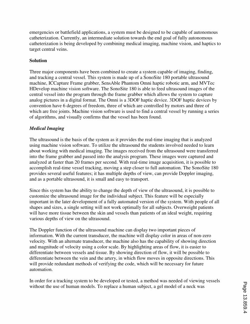
Optical Character Recognition (OCR) is a common method of using machine vision to identify
text in an image. For OCR programming in HDevelop, a training file must be created that
contains all of the characters that will need to be identified in images. During the training
process, the user inputs the text associated with each shape, and the program creates a font file
that associates shapes with letters or numbers. Once this font file is created, any shape identified
in an image can be compared to the shapes in the file, and the closest two values are returned,
along with the certainty of the program of each option. Generally, if the font in the image is the
same as the font used in training, and the image is clear, the first option is returned with 99.8%
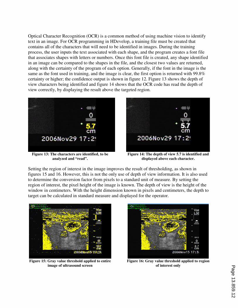
certainty or higher; the confidence output is shown in figure 12. Figure 13 shows the depth of
view characters being identified and figure 14 shows that the OCR code has read the depth of
view correctly, by displaying the result above the targeted region.
Figure 13: The characters are identified, to be
analyzed and “read”.
Figure 14: The depth of view 5.7 is identified and
displayed above each character.
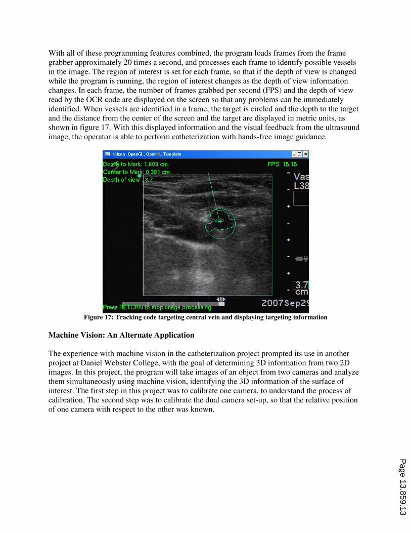
Setting the region of interest in the image improves the result of thresholding, as shown in
figures 15 and 16. However, this is not the only use of depth of view information. It is also used
to determine the conversion factor from pixels to a standard unit of measure. By setting the
region of interest, the pixel height of the image is known. The depth of view is the height of the
window in centimeters. With the height dimension known in pixels and centimeters, the depth to
target can be calculated in standard measure and displayed for the operator.
Figure 15: Gray value threshold applied to entire
image of ultrasound screen
Figure 16: Gray value threshold applied to region
of interest only Page 13.859.12
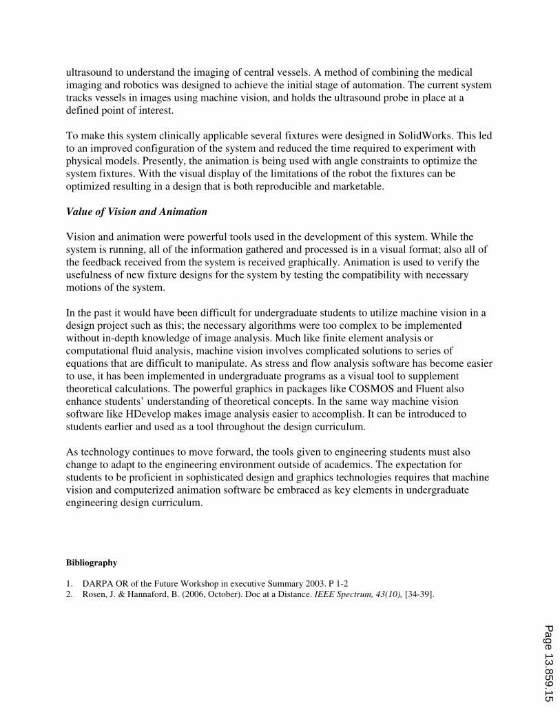
With all of these programming features combined, the program loads frames from the frame
grabber approximately 20 times a second, and processes each frame to identify possible vessels
in the image. The region of interest is set for each frame, so that if the depth of view is changed
while the program is running, the region of interest changes as the depth of view information
changes. In each frame, the number of frames grabbed per second (FPS) and the depth of view
read by the OCR code are displayed on the screen so that any problems can be immediately
identified. When vessels are identified in a frame, the target is circled and the depth to the target
and the distance from the center of the screen and the target are displayed in metric units, as
shown in figure 17. With this displayed information and the visual feedback from the ultrasound
image, the operator is able to perform catheterization with hands-free image guidance.
Figure 17: Tracking code targeting central vein and displaying targeting information
Machine Vision: An Alternate Application
The experience with machine vision in the catheterization project prompted its use in another
project at Daniel Webster College, with the goal of determining 3D information from two 2D
images. In this project, the program will take images of an object from two cameras and analyze
them simultaneously using machine vision, identifying the 3D information of the surface of
interest. The first step in this project was to calibrate one camera, to understand the process of
calibration. The second step was to calibrate the dual camera set-up, so that the relative position
of one camera with respect to the other was known.
Page 13.859.13

Figure 18: MVTec calibration plate
To complete individual camera calibration, images were taken of an MVTec proprietary
calibration plate; the plate is shown in figure 18. The machine vision software then uses several
commands to search for each of the calibration marks on the plate and returns a visual output of
the results in red. Figure 19 shows the search results of the first iteration of these commands,
which do not line up directly with each mark. Each time the program searches for and finds the
marks on the plate, it uses the previous search to improve the results (Figure 20). By displaying
the results of these searches, the user can verify that enough iterations have been performed. By
testing the program, it was determined that three iterations result in accurate definition of the
calibration marks.
Figure 19: First iteration of search for calibration
marks
Figure 20: Third iteration of search for
calibration marks
After finding the calibration marks, predefined functions in HDevelop were used that were
established for calibrating dual camera systems. The outputs of these functions were variables
defining the position of one camera with respect to the other. Without the use of machine vision
software, the students would have been unable to perform the low level algorithms of calibrating
the system, which requires knowledge of epipolar geometry and other graduate level research.
Conclusion
The long term goal of the medical project described is to achieve fully automated catheterization.
The current work included researching automated trauma resuscitation and working with an
Page 13.859.14
ultrasound to understand the imaging of central vessels. A method of combining the medical
imaging and robotics was designed to achieve the initial stage of automation. The current system
tracks vessels in images using machine vision, and holds the ultrasound probe in place at a
defined point of interest.
To make this system clinically applicable several fixtures were designed in SolidWorks. This led
to an improved configuration of the system and reduced the time required to experiment with
physical models. Presently, the animation is being used with angle constraints to optimize the
system fixtures. With the visual display of the limitations of the robot the fixtures can be
optimized resulting in a design that is both reproducible and marketable.
Value of Vision and Animation
Vision and animation were powerful tools used in the development of this system. While the
system is running, all of the information gathered and processed is in a visual format; also all of
the feedback received from the system is received graphically. Animation is used to verify the
usefulness of new fixture designs for the system by testing the compatibility with necessary
motions of the system.
In the past it would have been difficult for undergraduate students to utilize machine vision in a
design project such as this; the necessary algorithms were too complex to be implemented
without in-depth knowledge of image analysis. Much like finite element analysis or
computational fluid analysis, machine vision involves complicated solutions to series of
equations that are difficult to manipulate. As stress and flow analysis software has become easier
to use, it has been implemented in undergraduate programs as a visual tool to supplement
theoretical calculations. The powerful graphics in packages like COSMOS and Fluent also
enhance students’ understanding of theoretical concepts. In the same way machine vision
software like HDevelop makes image analysis easier to accomplish. It can be introduced to
students earlier and used as a tool throughout the design curriculum.
As technology continues to move forward, the tools given to engineering students must also
change to adapt to the engineering environment outside of academics. The expectation for
students to be proficient in sophisticated design and graphics technologies requires that machine
vision and computerized animation software be embraced as key elements in undergraduate
engineering design curriculum.
Bibliography
1. DARPA OR of the Future Workshop in executive Summary 2003. P 1-2
2. Rosen, J. & Hannaford, B. (2006, October). Doc at a Distance. IEEE Spectrum, 43(10), [34-39].
Page 13.859.15