machine lapping of quartz oscillator-plates wrrrrau
TRANSCRIPT
MACHINE LAPPING OF QUARTZ OSCILLATOR-PLATES
Wrrrrau Pannrsn,Research Laboratory,
North Arnerican Philips Co., Inc.Irvi.ngton, New York.*
Cotrnr.rrs
Abstract.Introduction. .
Acknowledgments.. . .Lapping Procedures. .
Transpositions... .Abrasives.Thickness to be Lapped Ofi. . . .
Quality of Lapped Crystals. .Controlling Stopping Point of Lap. .The Planetary Lap. . . . . . .
Work-Holders .. .Lap Plates.Operation of Lap. . . .
Miscellaneous Lapping Equipment.. . .O p t i c a l - T y p e L a p . . . . . . .
Q -Lap . .Drill Press Lap..Calibrating Machine Lap. .Seco Precision Crystal Finisher Type F.T. 413
MillingTechnique.. . 413
Ansrnacr
A description is given of several types of machine lapping methods and equipment usedin the manufacture of quartz oscillator-plates from the rough cut stage up to the finaletching-to-frequency operations. The blanks are lapped from ca.0.045" thick to 0.012" to0.018" depending upon the desired frequency and at the completion of the final stage themajor surfaces must be parallel to within a few fringes of Iight, have a fine finish (usuallywith 1303 optical flour), oscillate, and be close to final frequency (0.00004' above final thick-ness).
A three-stage high-speed lapping-to-frequency procedure using planetary-type motionlaps is described in detail. 30 to 55 crystals (depending upon their size) are carried in fiverevolving work-holders between two stationary lap plates so that both sidesarelappedatthe same time and rate. The weight of thetopplate, speed, and abrasive size are progres-sively reduced in the three stages. A group of crystals is transferred from one stage to thenext without intermediate grouping and one random transposition is made at ca.0.0006"from the final thickness to equalize thickness difierences and contour onbothsides.Totalthickness variation is *0.00002". A calibrated sensitive radio receiver coupled directly tomachine laps can be used to follow the progress of the crystals and to achieve precisioncontrol of the stopping point.
* Mail address: Dobbs Ferrv. N. Y.
Page3893903923923943963983993994044054064074084084104ll412
390 WILLIAM PARRISH
Various other types of lapping equipment and procedures are described. The converteddrill press lap is the most widely used in the crystal industry. The work-holder carryingthe crystals is driven between a pair of stationary lap plates; the calibrating machine lapworks on the same principle but is smaller. Optical-type laps have disadvantages forcrystal work and are not commonly used. A special lap for single crystals and the millingtechnique in which as many as 1000 crystals at a time are tumbled, are described.
INrnolucttow
This paper describes the machine lapping methods and equipment usedin the manufacture oI quartz oscillator-plates. The rough surface from thesawing operations must be removed and the blank properly lapped sothat it wil l oscil late. The rough cut blanks are ca.0.045' thick and arelapped to 0.012" to 0.018" depending upon the desired final frequency.
Some of the several problems which must be simultaneously solved inthe ideal lapping procedure are:
a. The lapped crystals must have the proper finish (usually with f303optical flour) and contour (approximately 0.0001" to 0.00005// thicker incenter than at four corners for 6 to 8 MC BT-cuts). The two major sur-faces should be parallel to within a few fringes of light.
b. The crystal surfaces, edges and corners must be free from scratchesand chips, and have the highest quality to prevent later diffi.culties infinal finishing and use.
c. AII crystals in each lap load must be closely alike in frequency at thecompletion of the final lapping stage. The approximate frequency spreadshould not exceed 10 to 15 KC for 6 MC BT-cuts which corresponds to0.00004'. This eliminates the necessity of accumulating huge stocks ofvarious frequencies, channel sorting, etc.
d. Recent experimental work has shown that 15 to 30 KC must beetched ofi 6 to 9 MC BT-cut crystals respectively, to prevent ageing.lTherefore each lap load of crystals must be brought to within 0.00004"of final thickness without overshooting in order to reduce hand finishingto a minimum and obtain uniform crystals.
e. The entire lapping operation should be only a small fraction of theentire manufacturing cost. This means a large volume of high qualitycrystals, with a low rejection rate and hence the methods and equipmentmust be simple so that comparatively unskilled help can use them in aroutine manner.
This study deals with the machine lapping of &", L" and f;" square BT-cut crystals in the 5 to 9 MC fundamental frequency range and f;" squareAT-cut crystals, 2 to 5 MC. In these types of crystals the frequency is
1 All lapped crystals age but the ageing is effectively stopped by etching ofi the dis-oriented surface layers after lapping. Frondel, Clifiord, Final frequency adjustment ofquartz oscillator-plates: Am. Mineral., this issue.
MACHI N E LAPPING OF OSCILLATOR-PLATES
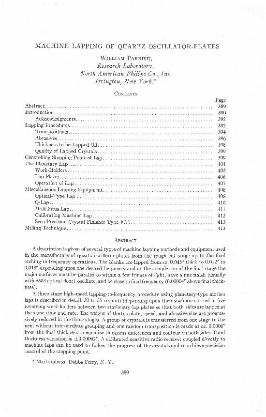
dependent upon the thickness
l 5 ? o 2 5 g o 3 5 4 0 6
391
Frequency 1Kg;:--- i- -.-, ! l : -{
Thickness (inches)' dT T2
and their relationship is shown graphicaily in Fig. 1. The frequency-
6000
5500
a 5ooo
Iu*a
F {o00
3500
55 60 65 70 75 80 85ItriclEes8 (tt@Bedthr of u tnch)
Frc' 1. Fundarnental frequency-thickness relationship for AT- and BT-cuts.
392 WILLIAM PARRISH
direct reading device such as the channel sorter described later, rather
than attempt precision thickness measurements'
It will be recognized that machine lapping oI quattz crystals is a high
precision job requiring a skillful procedure and good equipment' The
sudden unprecedented demand for crystals after Pearl Harbor produced
a variety of procedures and equipment hurriedly designed, with little
opportunity to study even the barest principles involved, in order to get
production started in the shortest possible time. Many of the funda-
mental problems have been solved and a few of the best practices will be
briefly summarized. Some of the methods are applicable to the prepa-
ration of polished and thin-sections for mineralogical work, especially
when used with the sawing procedures described in another paper in this
Journal.2Achnowled'gments. The work on high speed planetary lapping to fre-
quency was carried out under a development contract with the Signal
Corps of the U. S. Army through the Signal Corps Ground Signal Agency'
The work would not have been possible without their encouragement and
support.The writer is indebted to several engineers at N.A.P. for aid in this
work: Mrs. S. Tintos was in charge of the experimental work; the de-
scription of the radio receiver technique is based upon the development
work of Mr. John D. Davies; Mr. T.W.M. Schaffers and Mr' E' F'
Sheeder were responsible for the mechanical engineering; Mr' J' T'
Derbyshire took the photographs; Mr. Charles E. Goldmann and several
technical assistants carried out the detailed work' Mr. J. N. Bagwell' Jr'of Commercial Crystal Co., Lancaster' Pa. and Mr. P. R' Hoffman of
Carlisle, Pa. were consulted on several problems. Bli ley Electric Co.,
Erie, Pa. supplied Fig. 10 and information on the optical type lap'
Atlas Sales Co., Chicago, I l l ., supplied Fig. 12. Dr. Hal F. Fruth of GaI-
vin Mfg. corp. chicago, Il1. reviewed the section on milling methods and
contributed the data for Fie. 16.
LepprNc PnocBounBs
Only a few plants use a one-stage lapping process. A lapping stage re-
fers to the grinding of crystals to a specific thickness with one size of
abrasive. The three-stage process has proven the most successful al-
though the four-stage and even the two-stage processes are. in use.
The disadvantage of the single stage of lapping is that it requires a
longer time than in the case of several stages. As the clystals acquire the
2 Parrish, william, Methods and equipment for sawing quartz crystals: Am. Mi'neral.,
this issue.3 Now at Research Division. Reeves Sound Laboratories, Brooklyn, N' Y'
MACH IN E LAPPING OF OSCILLATOR-PLATES
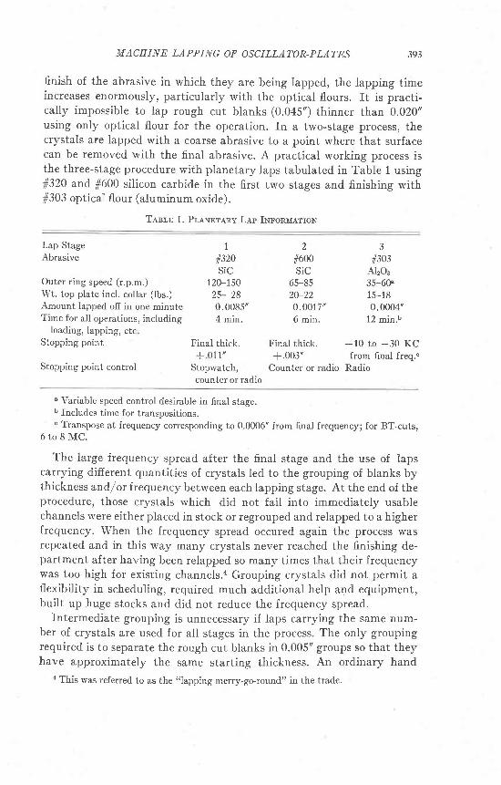
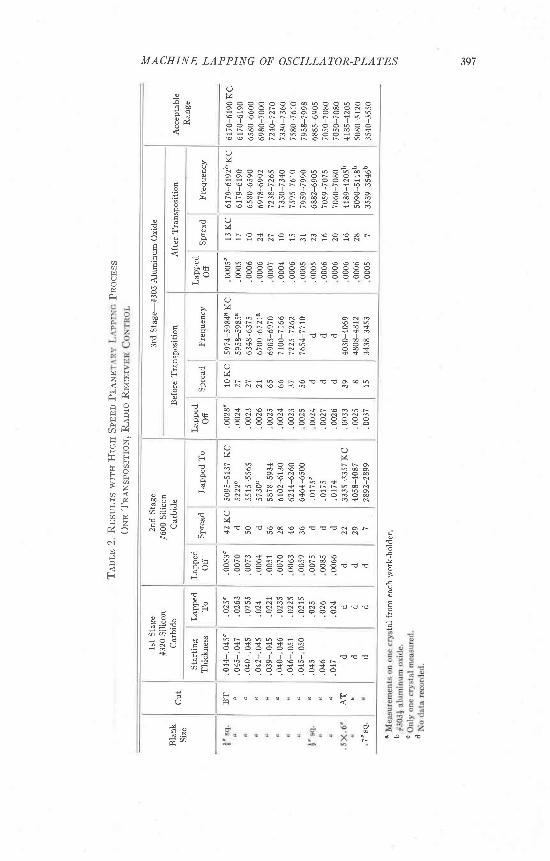
finish of the abrasive in which they are being lapped, the lapping timeincreases enormously, particularly with the optical flours. It is practi-cally impossible to lap rough cut blanks (0.045') thinner than 0.020"using only optical flour for the operation. In a two-stage process, thecrystals are lapped with a coarse abrasive to a point where that surfacecan be removed with the finai abrasive. A practical working process isthe three-stage procedure with planetary laps tabulated in Table 1 usingfi320 and f600 silicon carbide in the first two stages and finishing withf303 optical f lour (aluminum oxide).
Tesla 1. Pllxereny Lep Imronlrerron
393
Lap StageAbrasive
2#600SiC
65-8520-220 .001 7 '
1
#320 #303SiC
Outer ring speed (r.p.m.) 120-150Wt. top plate incl. collar (lbs.) 25- 28Amount iapped off in one minute 0.0085'Time for all operations, including 4 min.
loading, Iapping, etcStopping point
Stopping point control
6 min. 12 min.b
Final thick. Final thick. -10 to -30 KC+ 011" +.003' from final freq.o
Stopwatch, Counter or radio Radiocounter or radio
A12O335-60e_t J-16
0.0004'
u Variable speed control desirable in final stage.b Includes time for transpositions.o Transpose at frequency corresponding to 0.0006" from final frequency; for BT-cuts,
6 t o 8 M C .
The large frequency spread after the final stage and the use of lapscarrying different quantities of crystals led to the grouping of blanks bythickness andf or frequency between each lapping stage. At the end of theprocedure, those crystals which did not fall into immediately usablechannels were either placed in stock or regrouped and relapped to a higherfrequency. When the frequency spread occured again the process wasrepeated and in this way many crystals never reached the finishing de-partment after having been relapped so many times that their frequencywas too high for existing channels.a Grouping crystals did not permit aflexibility in scheduling, required much additional help and equipment,built up huge stocks and did not reduce the frequency spread.
fntermediate grouping is unnecessary if laps carrying the same num-ber of crystals are used for all stages in the process. The only groupingrequired is to separate the rough cut blanks in 0.005" groups so that theyhave approximately the same starting thickness. An ordinary hand
{ This was referred to as the "lapping merry-go-round" in the trade.
394 WILLIAM PARRISH
micrometer is sufficiently accurate for the purpose. After the first stage
of rough lapping, the crystals are kept as a group and transferred to the
second stage, and then to the final stage. If some crystals are broken
during the process, they are removed but none are added. At the end of
the second stage the crystals are then automatically more closely grouped
for thickness than is possible by any convenient production scheme now
in use.Transpositioas. One of the most difficult problems is to reduce the
frequency spread to a point where the large majority of the crystals can
be handled as one group in the finishing operations. The tolerable fre-
quency spread will depend upon the frequency and finishing methods;
10 to 30 KC below fi.nal frequency has been the usual acceptable limit
for 6 to 8 MC BT-cuts. This means that the crystals in a lap load must
have the same nominal thickness to ca. *0.00002't.A detailed study of the problem was made with the planetary type of
lap described below. This work involved lapping more than 10,000 crys-
tals, 50,000 frequency measurements and numerous production data, so
that it would be impossible to describe the numerous techniques tried.
Using either three, four or five work-holders and either two or three
stages of lapping, the frequency spread considerably exceeds the ac-
cepted l imits. Spreads up to 200 KC were obtained on 8 MC BT-cuts but
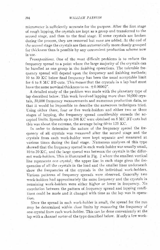
this was about the extreme, the average being 60 to 125 KC.In order to determine the nature of the frequency spread the fre-
quency of all crystals was measured after the second stage and the
crystals from each work-holder were kept separate and measured at
various times during the final stage. Numerous analyses of this type
showed that the frequency spread in each work-holder was usually small'
10 to 20 KC, and the large spread was between the crystals in the differ-
ent work-holders. This is illustrated in Fig. 2 where the smallest vertical
line represents one crystal; the upper line in each stage gives the fre-
quencies of all the crystals in the load and the smaller l ines underneath
show the frequencies of the crystals in the individual work-holders.
Various patterns of frequency spreads were observed. Generally two
work-holders had approximately the same frequency and the crystals in
remaining work-holders were either higher or lower in frequency. No
correlation between the pattern of frequency spread and lapping condi-
tions could be made and it changed with time as the lap was in opera-
tion.Since the spread in each work-hoider is small, the spread for the run
may be determined within close limits by measuring the frequency of
one crystal from each work-holder. This can be done conveniently at the
Iap with a channel sorter of the type described below. If only a few work-
After tnd stage, #600 si l lcon carblde
A]'l crystals
5 O
MACHINE LAPPING OF OSCILLATOR-PLATES 395
3rd stage, before transposltlot, #O03 aluntnun oxlde
AlI ctystals
IIoIder I
7460 7500
Frc. 2. Frequency spread within each work-holder is small but spread occurs betweenwork-holders and is reduced by transposition of crystals. Smallest vertical line representsone crystal. $" square BT-cut crystals.
zrffio3rd stage, after transposltl.on, #305 alurolnun oxide
l ,i l t l
Arr crvstars u ttlJllll'tll " "'
H o r d e r 1 " I t t ' t "b
g l r l r r t l l I E
l 5l t o
s LUru ebo
n I ' r l , t l io
I ' E5 U L U {
396 WILLIAM PARRISH
holders are found to be at the desired end frequency, these crystals are
removed from the lap and the remaining crystals of slightly lower fre-
quency redistributed in the work-holders and the lap given a few addi-
tional turns to eliminate the spread. In this way frequency spreads were
reduced from 53 to 18 KC, 70 to 30 KC, etc., at 8 MC.
It was determined empirically that if one random transposition was
made in the final stage at a frequency corresponding to 0.0006" from the
final frequency that the spread was reduced to the required limits. The
probable accuracy of this value is +0.0002" and should be redetermined
for a new set of conditions. If the transposition is made too far from the
final stopping point, the spread will again develop, and if made too close
to the final frequency, the spread will not be sufficiently closed. It was
found that several transpositions made during the procedure did not
further reduce the spread but in transferring the crystals from one stage
to the next a random transposition is automatically made. Figure 2 and
Table 2 vividly show the effectiveness of the transposition technique in
reducing the frequency spread.Several types of transpositions were tried but a simple and useful one
is to take all Ctystals from one work-holder keeping the upper surface
face up, and stack them in the palm of the hand. This is repeated until
all work-holders have been emptied and can be started from any work-
holder and followed clockwise or counterclockwise. The entire group of
crystals are then turned upside down so that the upper surface from the
previous lapping will now be down. Starting with any work-holder, the
top crystal from the stack is placed in the first work-holder, the second
crystal in the second work-holder and so forth until the lap is fiIled. If
some crystals are broken, the vacancies should be balanced on each side
of the lap.Transpositions are also useful in reducing the spread in the drill-press
type of lap.Abrasioes. The most frequently used abrasives for machine lapping are
#320 silicon carbide for the first stage, 1600 silicon carbide for the second
and f303 optical flour (aluminum oxide) or 1800 silicon carbide for the
final stage. #240 silicon carbide in water, laps almost two and a half times
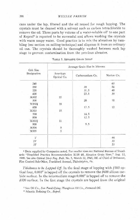
faster than 1600.5 Table 3 gives a summary of frequently used abrasive
sizes. One-quart jars containing approximately 6 oz. of abrasive and filled
with a lubricant such as Keystone Penetrating Oil #26 was used in the
high speed planetary lapping method. The used abrasive is collected in
6 Bond, W. L., Processing quartz: BeIt Lab- Recoril, ?2r 359-361 (1944)'6 Keystone Lubricating co., Philadelphia, Pa. have supplied the following information
regarding this oil: gravity Baum6 35.2; flash point 225oF.,fire point 280"F', Seybolt vis-
cosity 56 sec. at 100oF., 33 sec. at 210"F.
397
F
M ACH IN E LAPPING OF OSCILLATOR-PLAI:ES
r 9 ! ! ! 6o h
OMN ! O ! € € 9 € E d d N O t s
4 d < o d N
O
o o o o t s 9 H a o @ € o d b: F o o N q o o o o o N - h€ o o F o r N = h 4
J J J J J J J J ; J J J - -r r 6 € + o 6 4 € 8 4 € € +F F D O N - 6 O @ O O F O 49 € 9 € € r r $ b o
Ol1
N O O N b O O Q b r . O b 6 €o o 6 6 a 3 : o o N @ o : $: : 4 0 d o o 6 0 0 0 d i 4
9 9 9 9 \ r i \ r y 9 \ \ ! - b -r t t t t t r t l l
o o o @ 6 0 b o N 6 0 0 0 0N t s € F O O 6 b € 4 9 € O Oi i b o N o b a € o o * o b€ € € O € r \ t s + 4 A
U
S g , - g o € N o o q q@ € F N r € 9 : € : bo o o t s o * N N o @ +b b € € o r t s N + + t
o o t " i o ; J ; * o o o o - -F b + o o o ^ 6 - ) a * )o 6 0 r o : N € o @ +h b € € € t s r r 3 + o
O r rV J
+ o o o N F 6o € o o € Q b @ o
o r ^ b D o €q 4 D € A O r - + N' c T o I I I l b b + T I I
D N O O € N + + F N r h € do N : o t s o * € * i : s b 6o N D r @ : d + o o o o o €b q 6 q h € € 9 . , . o + N
h € : o$ 3 + + + + 4 b
+ b d N o o € h o o s - - -$ $ + $ o + $ $ $ + +
q
€q
A
F
F
O
€ t s o + r o 6 : o € o € € F: i H N N i i O N * N d N
b b € € F + € 6 b €
x x x = : x x x x :
O
o t s r : b €: N N N A €
€ + o € o + € D + t s € o 4 FN N d - N -
o o o + : o o o b D €E F F € D t s € h F 6 @
6 6 5 5 6 5 5 5 5 E 5 ' - -
H D b b6 € b + N D d i h € +
N N N N N N ^ ! ! !
E
J
a
k 'O
d4 o5 N
q E
J
!
tt
otr!
F]
E
F.]
!
E
F
Oo
2 A< x! p
H ?heo - i
t s x- z@ <t r &F.] Fi
t4. z
N
|l
F
B'
d
r7.
!
. = 5
a 7 ,
. ' - 9 0
a a l
a
398 WILLIAM PARRISH
cans under the lap, filtered and the oil reused for rough lapping. Thecrystals must be cleaned with a solvent such as carbon tetrachloride toremove the oil. Three parts by volume of a water-soluble oilT to one partof Reprols is reported to be successful and allows washing the crystalswith warm soapy water. Good practice is to mix the abrasives by tum-bling (see section on milling technique) and dispense it from an ordinaryoil can. The crystals should be thoroughly washed between each lapstage to prevent contamination from the previous abrasive.
Tasm 3. Annnsrvn GnnrN Srzns'
Averase Grain Size in Microns
Grit SizeDesignation
Carborundum Co. Norton Co.American
Optical Co.
240280320400
M302500
M302+600
M303700800
M303;900
M304M305
F2F3F
38
2 2 . 5
JA
1 7 . 5
t / (
t 2 . 5
9 . 5
22
18
1 5
63544030
1 8
t2
1 1
8
443323
n Data supplied by Companies noted. For smaller sizes see National Bureau of Stand-
ards "Simplified Practice Recommendation R118-40, Abrasive Grain Sizes," Aug. 15,
1940. See also Opticatr Shop Eng. BuIl.No.5, March t2,1945, Off. of Chief of Ordnance,
Fire Control Sub-Office, Frankford Arsenal, Philadelphia, Pa.
Thickness to be Lapped, Of .In the final stage of lapping with 1303 op-tical four, 0.003" is lapped ofi the crystals to remove the 1600 silicon car-bide surface. In the intermediate stage 0.008" is lapped off to remove the
f320 surface. In the first stage the crystals are lapped from the original
7 Sun Oil Co., Sun Emulsi'Jyi'ng; Houghton Oil Co., Permosol' Oil.8 Atlantic Refining Co., Reprol.
M ACE I N E LAPPING OF OSCILLATOR-PLATES
thickness to the final thickness plus 0.011". Thus a load of crystals whichis to be lapped to 6700 KC (approx. 0.015') would be lapped to 0.026" in
fr320, to 0.018' in 1600 and to final lap frequency in 1303.The amount to be lapped ofi the crystals in each stage was determined
from the maximum grain size of the various abrasives. It was assumedthat the maximum size of grain will produce a scratch of the same depthin the crystal. Since both sides are lapped, this value is multiplied by twoand a safety factor of 100/p added to each side so that the thicknesseswere calculated on the basis of at least four times the maximum grainsize of abrasive used. This procedure has been successful and assuresthat all lapped crystals have the same degree of optical flour finish re-gardless of frequency. Hence the crystals are properly prepared for thefinal etching-to-frequency operation. This is important for the lap finishmarkedly efiects the etching time and where the finish is not controlledthe etching rate is not predictable within the close limits usually re-quired.
Quality of Lapped, Crystals. Using the process described above, thecrystals have good activity after the final lap stage so that hand edgingat the finishing positions may be eliminated and the etching-to-frequencyprocess is simplified. It is not uncommon to lap crystals to an activity of0.4 to 0.7 where 0.3 ma. is passing in final test. Transpositions increasethe quality of the crystals by producing crystals with a similar contouron both sides and decreasing wedging. Edge and corner chips andscratches (usually caused by contaminated abrasives) are the principalcauses for rejection in the lapping process. The contour of the lappedcrystals may be observed with a pair of high precision optical flats at leasta few inches in diameter and a monochromatic light source such as a G.E. Sodium Lab-Arc. Quartz flatse are often used to prevent scratchingthe flats. The crystal is placed between the flats and the interference pat-tern observed at almost grazing incidence.
CoxrnorrtNc SropprNG PorNr ol Lep10
In all the lapping stages, it is important to be able to stop the lap atany desired crystal frequency or thickness. The need for precision con-trol, particularly in the final stage, will be evident from the following dis-cussion. If it is desired to lap a load of BT-cut crystals to 8000 KC, over-lapping them by 0.0010' will produce crystals approximately 700 KChigher than the desired frequency. In the final stage the stopping pointtolerance is exceedingly small. 6 to 8 MC BT-cut crystals must be ma-
e Acme Industrial Co., Chicago, Illinois.10 This section was prepared in collaboration with Mr. John D. Davies, N.A.P., Re-
search Laboratory, who also did much of the development work.
4OO WILLIAM PARRISH
chine lapped to within 10 to 30 KC below the final finishing frequencywhich corresponds to a few one-hundred thousandths of an inch in thick-NCSS.
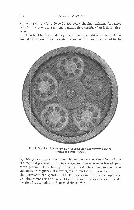
The rate of lapping under a particular set of conditions may be deter-mined by the use of a stop watch or an electric counter attached to the
Frc. 3. Top view of planetary lap with upper lap plate removed showingcrystals and work-holders.
lap. Many carefully run tests have shown that these methods do not havethe required precision in the final stage and that even experienced oper-ators generally have to stop the lap at least a few times to check thethickness or frequency of a few crystals from the load in order to followthe prol;ress of the operation. The lapping speed is dependent upon thegrit size, composition and rate of feeding abrasive, crystal size and finish,weight of the top plate and speed of the machine.
MACH INE LAPPING OF OSCILLATOR-PLATES
A far more precise and simple method employing a sensitive calibratedradio receiver has been developed for determining the stopping point inall stages of lapping. With this technique the increase in frequency andthe frequency spread of the crystals in the lap may be followed while thelap is in operation. The method is capable of high precision and elimi-nates guess work and difficulties in manual routine. It has been used forseveral years in a number of crystal plants but the writer is unaware of itsorigil.tr The method as described here has been so refined and simplifiedthat it may be placed in the hands of comparatively unskilled people withno background in radio who may be trained to use it successfully withina few hours.
In lapping with the planetary- or drill press-type of lap the crystalsare carried by work-holders between the stationary upper and lower lapplates. Except for the thin abrasive and oil mixture, the lap plates restdirectly on the crystals. During lapping the crystals are shock excited andemit a signal whose frequency is directly dependent upon the thickness-frequency constant of the type oI cut (AT and. BT, etc.) being lapped.This is an application of the familiar piezoelectric phenomenon of voltageproduced by mechanical stress. The random voltages produced by thelapping action are sharply and strongly peaked at the thickness-fre-quency of the crystal (the crystal may be considered as a very high-Qtuned circuit.)12
A sensitive communications-type receiver is used to obtain the required deiicacy ofadjustments. rn this work a Skyid.er 32 (Fig. 4) rvas used.ls rhe receiver-to-lap connectionsare shown in Fig. 5. The correct coupling is important because the average signal strengthis of the order of a few microvolts and hence there is the problem of signal to noise ratio.Furthermore, since a sensitive receiver is used, the upper lap plate becomes an efiectiveantenna and in the average industrial plant there is considerable electrical interference.one antenna post is connected to the upper lap plate and the other to the Iower lap plateby means of the abrasive-guard shield which is more convenient than a direct connection.A common external ground isused for receiver and lap. Shielded cable isused fortheseconnections to reduce the possibility of their acting as an antenna.
The upper and iower lap plates are separated by the crystals being lapped. Bakelitetubing is slipped over the two pins on the collar of the upper lap plate to prevent shortingto the lower lap plate. Bakelite workholders are used also for the purpose of preventingshorting. Zinc work-holders have been used when they are much thinner than the crystalsfor otherwise they short the two lap plates and the noise interferes with the signal comingfrom the crystals being lapped.
11 About a year after the experimental work was completed, a patent was found whichdescribed essentially the same method: Bailey, Richard S, Piezoelectric apparatus andmethod: U. S. Patent Ofi.ceNo 2,340,843, Feb. 1, 1944.
12 Van Dyke, K. S., The piezoelectric resonator and its equivalent network: Proe . Insl.Radio Eng. 16, 7 42-7 64 (1928).
13 Manufactured by The Hallicrafters Co., Chicago, Ill.
401
402 WILLIAI,I PARRISE
The receiver is calibrated at the frequency at which the lap is to be stopped by means of
a calibrated oscillator loosely coupled to the former. A crystal oscillator with a standard
crystal may be used but has the disadvantage of requiring a crystal for each desired fre-
quency and also lacks flexibility. A simple and convenient method is to use a direct-reading
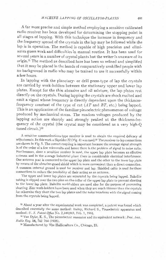
calibrated variable oscillator, often called a ehannel sorter in the crystal industry (see Figs' 4
and 8). These have been built for the 1 to 5 and 5 to 9 MC ranges which covers the ordinary
lapping frequencies. The variable oscillator has a large tuning dial marked to 5 or 10 KC
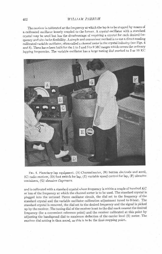
Frc. 4. Planetary lap equipment. (A) channelsorter, (B) button electrode and anvil,
(C) radio receiver, (D) foot switch for lap, (E) variable spee{ control for lap, (F) abrasive
containers, (G) abrasive dispensers.
and is calibrated with a standard crystal whose frequency is within a couple of hundred KC
receiver dial setting is then noted, as this is to be the final stopping point'
M ACHIN E LAPPING OF OSCILLATOR-PLATES 403
404 WILLIAM PARRISH
Head-phones, a loud speaker, or a record.er may be used to detect the signal but the
first was found to be the most practical. In fact the stopping point may be automatically
controlled.
further consolidates ail operations into one position'
The radio receiver method may be applied to the lapping of other
nonmetallic substances. For example, glass blocks couid be lapped and
their thickness followed by tuning in to a few quartz crystals of the same
thickness placed in the same laP.
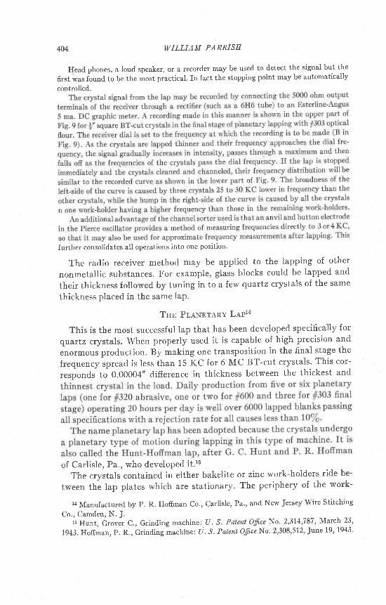
Tnn PT,aNBTARY LAP14
This is the most successful lap that has been developed specifically for
qvartz crystals. When properly used it is capable of high precision and
enormous production. By making one transposition in the final stage the
frequency spread is less than 15 KC for 6 MC BT-cut crystals. This cor-
responds to O.OOOO+' difference in thickness between the thickest and
of Carlisle, Pa., who developed it.16The crystals contained in either bakelite or zinc work-holders ride be-
tween the lap plates which are stationary. The periphery of the work-
la Manufactured by P. R. Hoffman co., carlisle, Pa., and New Jersey wire Stitching
Co., Camden, N. J.fi Hunt, Grover C., Grinding machine:. U. S. Patent Ofine No' 2,314,787, March 23,
1943. Hofiman, P. R., Grinding machine: tl . S. Patenl Ofice No' 2,308,512, June 19, 1943'

MACEINE LAPPING OF OSCILLATOR-PLATES
holders is toothed so that they mesh with the outer and inner ring gearsbetween the lap plates. The ring gears, driven by u * h.p. 3-phase motorin the under part of the housing, drive the work-holders and cause themto rotate and produce a broad sweeping lap motion. fn addition, eachcrystal is free to rotate within the pentagonal hole of the work-holderand this produces the spinning motion.
I|rork-Holders. The selection of proper work-holders is important inplanetary lapping. Large frequency spreads, poor contour, low activity,chipping, etc., may result from the use of poor work-holders. Two typesof material are widely used: linen-base bakelite and. zinc. Although thelatter has greater strength, it is a conductor and can be used with the
Frc. 6. Work-holders for lapping crystals. (A) Planetary lap, blank, (B) planetary lap,|" crystal, straight side, (C) planetary lap, f;/ crystal, straight side, (D) planetary lap,3q" crystal, straight side, (E) planetary lap, !', crystal, curved side, (F) planetary lap, forlapping ultrasonic plates, (G) drill press lap, !,, crystal, curved side, (H) calibrating lap|" crystal, slightly curved side.
Frc. 7. Planetary lap plates. (A) Lap surface of upper plate, (B) top view of upperplate, (C) bottom view of lower plate, (D) lap surface of lower plate, (E) removablehandles for changing gear position of lower piate.
radio method only when the crystals are considerably thicker than thework-holders for otherwise the two plates will be shorted. Bakelite ispreferred also because it produces less chipping, less wear on the gearsand less damage in a crack-up. Several types of work-holders are shownin Fig. 6.
one of the principal difficulties in using bakelite work-holders is that they tend tobecome warped. Paper-base, double-and higher-ply, and single-ply linen base bakelite areused and they are listed in increasing order of their tendency to warp. Paper-base bakeliteis so weak it can only be used with very light weight top plates such as in the small Bagwellplanetary lap16 or the calibrating Machine Lap. warped holders can sometimes be used by
16 A srnall planetary lap employing small work-holders and a light weight top platedeveloped by J.N. Bagwell Jr., Commeicial Crystal Co., Lancaster, pa.
405
406 WILLIAM PARRISH
wetting them thoroughly with the abrasive mixture and placing the crystals in the middle
of the hole rather than against the sides when loading the lap. When the top plate is put in
place it will flatten the work-holder so that the crystals may not slip under the hole and
cause a crack-up.AII five work-holders for the planetary lap should be grouped for thickness within
0.001'. Zinc work-holders should be lapped-inwithout crystals until most of the high spots
disappear. Bakelite work-holders should not be lapped-in because it weakens their teeth.
The work-holders should be at least 0.002" thinner than the final lappbd thickness of the
crystal.Pentagonal holes with sides slightly larger than the longest edge of the crystal allow
the crystal to rotate during lapping and produce crystals with a proper contour for high
activity. The corners may be cut back to reduce chipping the corners of the crystals.
Curved-side pentagonal holes are also often used but the relative merits have not been
rigorously determined.lT Square holes in which the crystal fits snugly are undesirable be-
cause the crystals become wedg.e-shaped. The holes in which the crystals are contained
must be so positioned that the crystals slightly over-ride the inner and outer periphery of
the lap plate. This prevents excessive lapping of the edges and permits control of surface
contour by varying the amount of over-ride,Thurston has described a novel work-holder which may eliminate edge chipping'l8 The
crystals fit snugly in a square hoie cut in a small circular disc. The discs fit into a work-
holder of the same thickness which has six circular holes just large enough to accommodate
the discs and allow them to rotate during lapping. This paper should also be consulted for
a description of a newly developed Iapping machine for quartz crystals.
Lap Plates. Both upper and lower lap plates (Fig. 7) are normalizedmeehanite, 15 5/8' in diameter with a 5f" diameter center hole. Theplates are used as a pair and should lie one on top of the other at aII timesto prevent warping and contamination. A pair of plates is used for eachabrasive. Four series of extra radial holes countersunk at the top, aredrilled in the upper lap plate to allow a more even feeding of the abrasive.Both plates have square serrations on the lapping surfaces which are t"apart on the upper plate and l" apafi on the lower plate. No publishedstudy of the effect of various types of serrations on lapping quartz hasbeen made. Cast iron lap plates with serrations lap crystals almost twiceas fast as smooth plates and as fast as smooth hard tool steel plates.leGlass lap plates are faster than smooth cast iron plates but the crystalsand work-holders tend to stick to the lower surface of the upper platewhen removing it from the machine. In addition to increasing the lappingspeed, the serrations allow a more even distribution of abrasive so thatthe entire surface of the crystals receives an even lapping action and theedges are not lapped thinner than the center.
17 Hunt, Grover C., Work-holder for grinding machines :U. S. P atent Ofi.ce No 2,309,080,
Jan.19,1943.r8 Thurston, G. M., Flatness and parallelism in quartz plates: Bel,l Lob. Reeord,,22,
435-439 (1944).re Bond, W. L,, op. cdt,
][ACH I N E LAPPING OF OSCILLATOR-PLATES 407
Both plates have inner ($$") and outer rings (l{' wide) which should be at least0'005" and not more than approximately 0.010" below the lapping surface of the plate. Therings permit the crystals to slightly overlap the inner and outer edges of the lapping platesurface so that the latter will remain flat out to the edges. As the plate wears, the ringsmust be pounded back into position with a soft hammer.
An upper lap plate weighing approximately 25 to 28 lbs. is used for coarse lapping with1320 abrasive. Progressively lighter weight plates should be used for the intermediate andfinal stages of lapping to permit the use of thinner bakelite work-holders and reduce ex-cessive breakage of crystais and damage to the plates in crack-ups. upper lap platesweighing 20 to 22 lbs. have been used for the intermediate lapping stage with 1600 abrasive.rn the final stage of lapping with 1303 optical flour, a greatly reduced plate weighing only15 to 18 lbs. is required if thin linen-base bakelite work-holders are to be used. These valuesinclude the weight of a 3 lb. special collar which has been added (see description below).The exact weight does not appear to be critical.
The flatness of the plates can be quickly determined by removing the plates from thelap and lapping by hand one against the other with the same abrasive as is used with theseplates for a few minutes. Low areas then become apparent when the plates are separatedand the lap surfaces inspected. A flat piece of accurately ground stock laid across thediameter of the plate on four small pieces of paper placed on the inner and outer peripheryof the lap surface on both sides of the center hole maybe used tomeasuretheunevennessof the plate. rf the plate is perfectly flat, the pieces oi paper cannot be pulled from underthe stockwhen the latter is held firmiyin place. rf one or more can be pulled out,the de-parture from flatness at those points may be determined by using two or more pieces ofpaper until they cannot be pulled out and then measuring the total thickness with amicrometer.
Before being placed in use, the lap plates are ground flat on a large surface grinder andthen lapped-in with the same abrasive as will be used on those plates. For this purposethree gears the same size as the work-holders but about f;" thick with the center milled outleaving a $" ring gear are used. The gears are put in place and the lap run until the platesare flat.
rf crystais or work-holders break during lapping, the prates and gears must be thor-oughly cleaned with a hard brush and the serrations with an awl. Cloths and towels shouldnot be used on the plates for lint and stringers tend to collect in the serrations.
tool to lift the plate from the carriage will expedite the change. The plate is then lifted andturned to the next position, the latter being fixed by a stepJike arrangement on the underside of the plate (Fig. 7). rn this way the wear on the gear is equalized, and after it becomesworn the gear is turned upside down and used in the same way for only one side of the teethDecome worn.
operation of Lap. rt must be emphasized that constant attention tominute details and a set routine such as checking ring depth, setting
408 WILLIAM PARRISH
plates to new gear position, careful washing and inspection of crystals
between stages, etc., are required to obtain good results. The work-hold-
ers should be checked and evenly spaced in the lap' The crystals are
placed against the side of the pentagon' or in the middle if the work-
holder is warped. Abrasive is squirted between the work-holders, the top
plate and center arm put in position and more abrasive poured through
ihe feed holes in the top plate. The outer gear is rotated counterclockwise
by hand several times with the operator listening for any sign of a crack-
up. The radio operator runs the lap by means of a foot switch and watches
Frc. 8. Simplified block diagram of channel sorter'
the progress of the lap by turning the main tuning dial of the receiver
back and forth across the signal while the lap operator feeds abrasive at
regular intervals. At the end of the run, the spread may be determined
by measuring one crystal from each work-holder with the channel sorter.
MrscBrr-aNnous LAPPTNG EQurpuBwr
There has been no published extensive study of the lapping proce-
dures in current use in the crystal industry. The following descriptions
are based upon observations of several dozen plants mainly in the East.
Space and time limitations allow a brief description of only a few of these.
Opticat-Type Lap. The crystals are cemented to a flat plate and one side
is lapped (Fig. 10). The crystals are then removed, the lapped side ce-
mented to a plate and the second side is lapped. This type of lap has
certain disadvantages for quartz work and is used by only a few plants in
the crystal industry. It may prove to be useful in the preparation of very
UNTITNEDPIERCEOSCILLATOR
IIXEB-DEIECTOR
CAI,IBRATEDVARIAALEOSCILLATOR
E:ED,lo
2(,HU)
JIACHINE LAPPING OF OSCILI,ATOR-PLATES 409
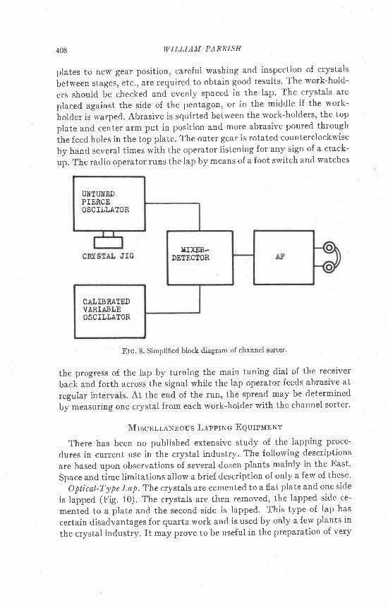
thin plates, which have been previously lapped by the usual proceduresto approximately 0.010".
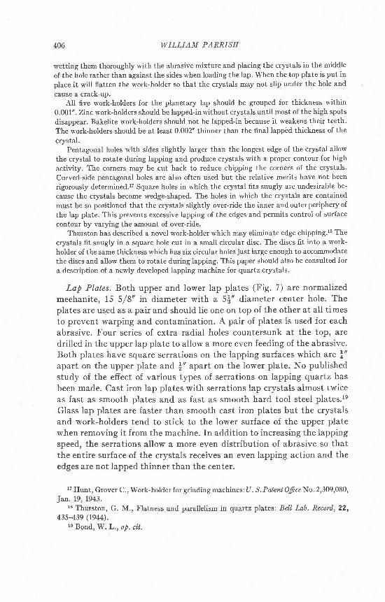
The "machine employs a l5!" diameter cast iron lap rotating at aspeed of 77.2 r.p.m. against which is driven at a speed approximately99 r.p.m. the crystal mounting plate. For the average crystal work this
c .
FRSQUENCI
Frc. 9. Graphic recording (above) of crystal signals from final stage of planetary lappingwith 1303 optical flour. Receiver dial set atfrequency B. Lap stopped immediately afterrecording and individual crystals measured with frequencies shown below. Smallest verticalIine represents one crystal.
mounting plate is 9f" diameter and approximately 1$" thick and is alsomade of cast iron and is lapped flat on both sides and parallel to approxi-mately .000010' over the entire usable surface.
"The crystals are mounted on this plate with paraffin, taking care onthe last side lapping especiaily to have an absolute minimum quantityof paraffin on the surface and carefully controlled heating. In this way
| r ) o o o o o6 l t o r r i ( o b = @@ o @ @ @ @t-. b- F- t- r-- t-
oFl
F{|a
H()ko
B
gDa
410 WILLIAM PARRISE
we can control the mounting error so that only a very small percentageof the crystals on the plate will be out of parallel by more than .000020"from corner to corner. The mounting plate is driven by means of a crankpin engaging a hardened steel center insert in the mounting plate. Thethrow of the crank as well as its center of rotation in relation to the lapare varied to maintain a flat working surface on the lap as well as to con-trol the flatness across the mounting plate and the contour of each indi-vidual crystal. The work on the mounting plate is measured by means of
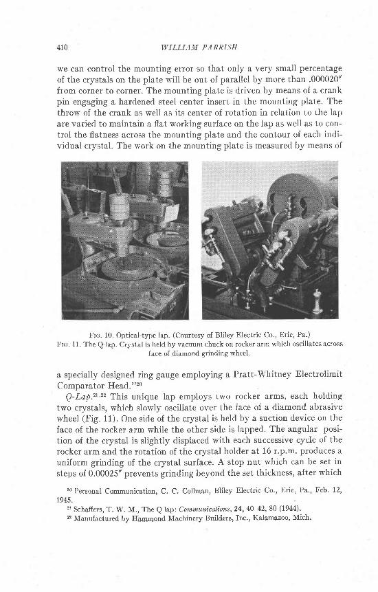
Frc. 10. Optical-type lap. (Courtesy of Bliley Electric Co., Erie, Pa.)
Frc. 11. The QJap. Crystal is held by vacuum chuck on rocker arm rvhich oscillates across
face of diamond grinding wheel.
a specially designed ring gauge employing a Pratt-Whitney Electrolimit
Comparator Head."2o
Q-Lap."''z This unique lap employs two rocker arms, each holdingtwo crystals, which slowly oscillate over the face of a diamond abrasivewheel (Fig. 11). One side of the crystal is held by a suction device on theface of the rocker arm while the other side is lapped. The angular posi-
tion of the crystal is slightly displaced with each successive cycle of therocker arm and the rotation of the crystal holder at 16 r.p.m. produces auniform grinding of the crystal surface. A stop nut which can be set insteps of 0.00025" prevents grinding beyond the set thickness, after which
20 Personal Communication, C. C. Collman, Bliley Electric Co., Erie, Pa., Feb. 12,
1945.21 Schafiers, T. W. M., The Q lap: Communications,24,40-42,80 (1944).22 Manufactured by Hammond Machinery Builders, Inc., Kalamazoo, Mich.
MACHINE LAPPING OF OSCILLATOR.PLATES
the handle is retracted and the rocker arm locked in the idling position.Best results were obtained with a resinoid bonded diamond wheel, 8|"diameter, 100-grit size, f50 concentration, running at 1750 r.p.m. anda mixture ol 20-30/e turpentine and 80-70/6 kerosene by volume forcoolant.
The QJap has been employed by only one crystal manufacturer. Itsprincipal uses have been in grinding thick wedge-shaped blanks to paral-Ielism with a reference surface, reducing extra thick cuts to a nominalthickness for lapping and in correcting off-angle blanks. In making test-
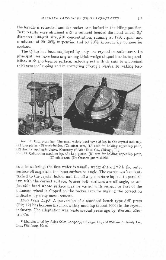
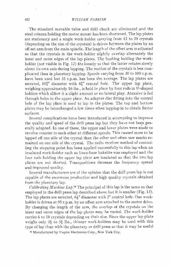
Frc. 12. Drill press lap. The most widely used type of lap in the crystal industry.(A) Lap plates, (B) work-holder, (C) ofiset arm, (D) rods for holding upper lap plate,(E) disc for lapping-in plates. (Courtesy of Atlas Sales Co., Chicago, Ill.)Frc. 13. Calibrating machine lap. (A) Lap plates, (B) arm for holding upper lap plate,
(C) ofiset arm, (D) abrasive guard shield.
cuts in wafering, the first wafer is usually wedge-shaped with the outersurface off angle and the inner surface on angle. The correct surface is at-tached to the crystal holder and the off-angle surface lapped to parallel-ism with the correct surface. Where both surfaces are off-angle, an ad-justable head whose surface may be varied with respect to that of thediamond wheel is slipped on the rocker arm for making the correctionindicated by x-ray measurement.
Dri.ll Press Lap.23 A conversion of a standard bench type drill press(Fig. 12) has become the most widely used lap (about 2000) in the crystalindustry. The adaptation was made several years ago by Western Elec-tric Co.
a Manufactured by Atlas Sales Company, Chicago, Ill., and William A, Hardy Co.,Inc., Fitchburg, Mass,
411
412 WILLIAM PARRISH
The standard movable table and drill chuck are eliminated and thesteel column holding the motor mount has been shortened. The lap platesare stationary and a single work-holder carrying from 12 to 20 crystals(depending on the size of the crystals) is driven between the plates by anoff-set arm from the main spindle. The length of the ofiset arm is adjustedso that the crystals in the work-holder slightly overlap alternately theinner and outer edges.of the lap plates. The bushing holding the work-holder (not visible in Fig. 12) fits loosely so that the latter rotates slowlyabout its own axis during lapping. The motion of the crystals is less com-plicated than in planetary lapping. Speeds varying from 30 to 100 r.p.m.have been used but 55 r.p.m. has been the average. The lap plates areserrated, 10f;" diameter with 4f;" central hole. The upper lap plate,weighing approximately 16 lbs., is held in place by four rods in U-shapedholders which alllow it a slight amount or no lateral play. Abrasive is fedthrough holes in the upper plate. An adapter disc fitting into the centralhole of the lap plate is used to lap in the plates. The top and bottomplates may be interchanged a few times when lapping-in to obtain flattersurfaces.
Several complications have been introduced in attempting to improvethe quality and speed of the drill press lap but they have not begn gen-
erally adapted. In one of these, the upper and lower plates were made torevolve counter to each other at different speeds. This caused more to belapped off one side of the crystal than the other and often saw marks re-mained on one side of the crystal. The radio receiver method of control-ling the stopping point has been applied successfully to this Iap when aninsulated work-holder such as linen-base bakelite was employed and thefour rods holding the upper lap plate are insulated so that the two lapplates are not shorted. Transpositions decrease the frequency spreadand improved quality.
Several manufacturers are of the opinion that the drill press lap is notcapable of the enormous production and high quality crystals obtainedfrom the planetary lap.
Calibrating Machine Lap.2a The principal of this lap is the same as thatemployed in the drill press lap described above but it is smaller (Fig. 13).
The lap plates are serrated, 6|t' diameter with 2" central hole. One work-holder is driven at 95 r.p.m. by an ofiset arm attached to the motor drive.By changing the length of the arm, the overlap of the crystals on theinner and outer edges of the lap plates may be varied. The work-holder
carries 6 to 10 crystals depending on their size. Since the upper lap plate
weighs only 3| to 5$ Ibs., thinner work-holders may be used with this
type of lap than with the planetary or drill press so that it may be useful2a Manufactured by Empire Electronics Corp., New York City.
MACHINE LAPPING OF OSCILLATOR-PLATES 413
for thin crystals. A disc fitting into the central hore of the upper lap prateis attached to the eccentric arm for lapping the plates together when thework-holder is removed.
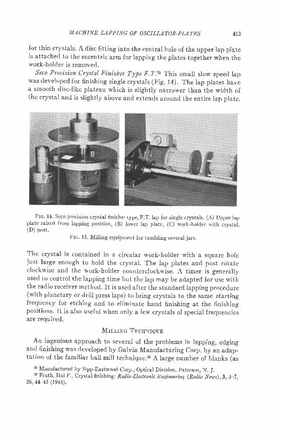
Seco Precision Crystal Finisher Type F.T.rb This small slow speed lapwas developed for finishing single crystals (Fig. 1a). The lap prates havea smooth disclike plateau which is slightly narrower than the width ofthe crystal and is slightly above and extends around the entire lap prate.
Frc. 14. Seco precision crystal finisher type, F.T. lap for single crystals. (A) Upper lapplate raised from lapping position, (B) lower lap plate, (c) work-holder with crystal,(D) post.
Frc. 15. Miliing equipment for tumbling several jars.
The crystal is contained in a circular work-holder with a square holejust large enough to hold the crystal. The lap plates and post rotateclockwise and the work-holder counterclockwise. A timer is generallyused to control the lapping time but the lap may be adapted for use withthe radio receiver method. rt is used after the standard lapping procedure(with planetary or drill press laps) to bring crystals to the same startingfrequency for etching and to eliminate hand finishing at the finishingpositions. rt is also useful when only a few crystals of special frequenciesare required.
Mrrr,rlTc Tncnnreuc
An ingenious approach to several of the problems in lapping, edgingand finishing was developed by Galvin Manufacturing Corp. by an adap-tation of the familiar ball mill technique.26 A large number of blanks (as
% Manufactured by Sipp-Eastwood Corp., Optical Division, paterson, N. J.26 Fruth, Hal F., Crystal finishing: Ratlio-Electronic Engineering (Rod,io Neus), 3, 3-7 ,26,44-45 (rg44).
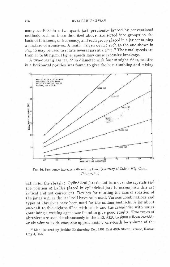
414 WILLIAM PARRISH
many as 1000 in a two-quart jar) previously lapped by conventionalmethods such as those described above, are sorted into groups on the
basis of thickness, or frequency, and each group placed in a jar containing
a mixture of abrasives. A motor driven device such as the one shown inFig. 15 may be used to rotate several jars at a time.2I The usual speeds are
from 35 to 60 r.p.m. Higher speeds may cause excessive breakage.A two-quart glass jar, 6" in diameter with four straight sides, rotated
in a horizontal position was found to give the best tumbling and mixing
Frc. 16. Frequency increase with milling time. (Courtesy of Galvin Mfg' Corp ,
Chicago, Ill.)
action for the abrasive. cylindrical jars do not turn over the crystals and
the position of baffies placed in cylindrical jars to accomplish this are
critical and not convenient. Devices for rotating the axis of rotation of
the jar as well as the jar itself have been used. Various combinations and
types of abrasives have been used for the milling methods. A jar about
one-half to five-eighths filled with solids and the remainder with water
containing a wetting agent was found to give good results. Two types of
abrasives are used simultaneously in the mill. fr320 to 1800 silicon carbide
or aluminum oxide comprise approximately one-tenth by volume of the
27 Manufactured by Jenkins Engineering co., 2301 East 48th street Terrace, Kansas
City 4, Mo.
tr,IACEINE LAPPING OF OSCILLATOR.PLATES 415
solids and do the grinding while a dense material such as garnet or co-rundum in the form of pebbles (5-10 mesh) supplies the pressure. Theamount oI quartz removed is linearly related to milling time and due tothe extremely small pressures, the method is much slower than the usualIapping techniques. The rate of frequency increase will depend amongother factors on the frequency-thickness curve and the starting frequencyas shown in Fig. 16. When such factors as velocity of rotation, shape ofcontainer, type of abrasives, etc., are controlled the results are reproduc-ible within very close l imits. The method does not equalize thicknessdifferences. In practice, the crystals are channelled (frequency grouped)within very close limits if a small frequency spread is desired at the end ofmill ing. If this procedure is not followed, all the crystals are removedfrom the mill at stated intervals and channelled. Those that are withinthe frequency tolerance are removed and those below the specified rangeare returned to the mili for further milling and the process repeated. Analternative procedure is to start the mill with the group of crystals whichis furthest away from the final desired frequency and then to add thechannelled groups one at a time in progressively increasing frequency ofthe next channelled group.
The methoC is used to increase the frequency only a small amount,approximately a few hundred K.C being the maximum for a 6 MC BT-cut while 25 KC is the usual amount removed. The rate of removal ofquartz is very small and the contour and edges of the crystals may seri-ously deteriorate if mil led for long periods. The method is said to be sub-ject to such control that most of the abrasion is on the major surfaces ofthe blanks, or if desired, the edges can be made to abrade relatively morerapidly.
The method has been employed by several crystal plants and has beenmost successful where large production quantities of closely spaced fre-quency channels are required as in the present crisis. The mass etchingprocedures which are now used as standard finishing practice and thehigh speed precision lapping techniques available today are capable ofhuge precision-controlled production so that it is difficult to evaluate itsimportance as a technique that will be useful in the future. A possibleapplication of the method is in the manufacture and final frequency ad-justment of very thin crystals. The method has been useful in edgingand washing crystals.