mach3 engraving machine interface board 5-axis
TRANSCRIPT

User Manual
MACH3 Engraving Machine Interface Board 5-axis

Contents
1 Introduction and Features .......................................................................................................... 1
1.1 Introduction ................................................................................................................... 1
1.2 Features ......................................................................................................................... 1
2 Specifications ............................................................................................................................ 1
3 Interfaces ................................................................................................................................... 2
4 Wiring Diagram for Reference .................................................................................................. 3
5 MACH3 Software Settings ....................................................................................................... 3
1
1 Introduction and Features
1.1 Introduction
The latest upgraded 5 axis breakout board is specially designed for the CNC single axis 2-phase
stepper driver controller, such as M542, M542H, MA860H, 2M542, 2M982, DM542(A),
DM860(A) etc. single axis stepper driver controller series. With this 5 axis breakout board, any
1-5 single axis stepper driver controllers can be directly controlled by the PC via the MACH3,
EMC2, KCAM4, etc.
1.2 Features
Maximum support 5-axis stepper motor driver controllers
Compatible with MACH3, Linux CNC (EMC2) etc. parallel-control CNC software.
USB power supply and peripherals powered phase are separated to protect computer security.
All the signals are opto-isolated which can protect your computer security.
5-input interface to define the Limit, Emergence-Stop, Cutter alignment, etc.
Wide input voltage range: 12-24V, and with anti-reverse function.
One relay output control interface, accessed by the spindle motor or the air pump, water
pump, etc.
Output 0-10V analog voltage for inverter to control the spindle speed.
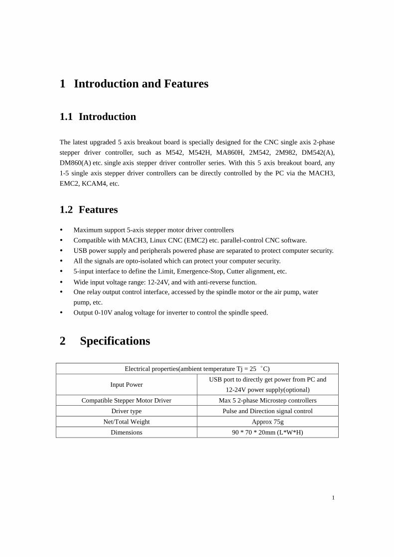
2 Specifications
Electrical properties(ambient temperature Tj = 25︒C)
Input Power USB port to directly get power from PC and
12-24V power supply(optional)
Compatible Stepper Motor Driver Max 5 2-phase Microstep controllers
Driver type Pulse and Direction signal control
Net/Total Weight Approx 75g
Dimensions 90 * 70 * 20mm (L*W*H)

2
3 Interfaces
3
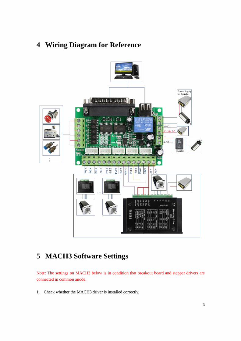
4 Wiring Diagram for Reference
5 MACH3 Software Settings
Note: The settings on MACH3 below is in condition that breakout board and stepper drivers are
connected in common anode.
1. Check whether the MACH3 driver is installed correctly.

4
2. Setup Units: Choose “MM’s” in Config->Set Default Units for Setup
3. Click “Config”->”Ports and Pins” on Main Interface.

5
4. Enter in “Port Setup and Axis Selection” to set “Port#1” and “Kernel Speed” shown as
below.
5. Click “Motor Outputs” to set it shown as below.
6. Click “Iutput Signals” to set it shown as below.

6
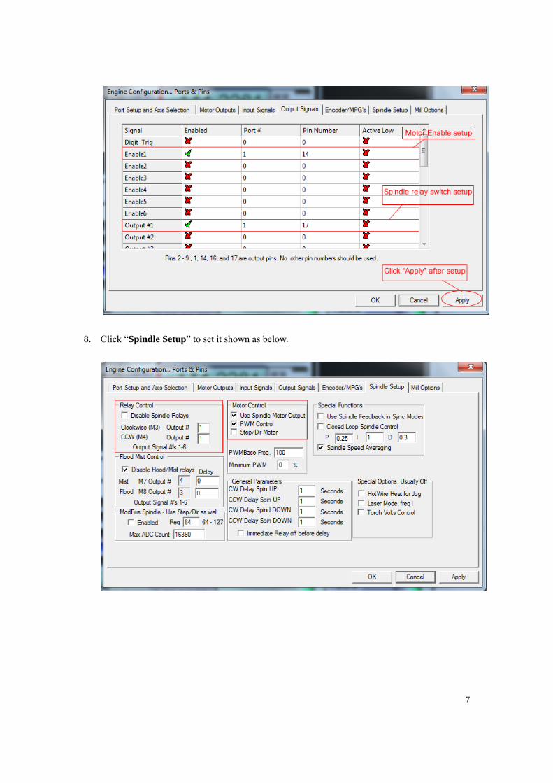
7. Click “Output Signals” to set it shown as below.
7
8. Click “Spindle Setup” to set it shown as below.
8
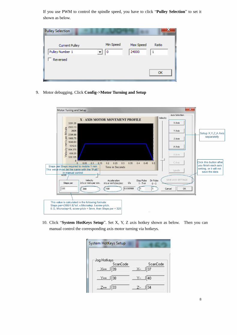
If you use PWM to control the spindle speed, you have to click “Pulley Selection” to set it
shown as below.
9. Motor debugging. Click Config->Motor Turning and Setup
10. Click “System HotKeys Setup”. Set X, Y, Z axis hotkey shown as below. Then you can
manual control the corresponding axis motor turning via hotkeys.