mac architecture for broadband satellite access …tahar/theses/tallal-thesis.pdf · mac...
TRANSCRIPT

MAC Architecturefor BroadbandSatelliteAccess
Systems
April 20,2000

Abstract
MAC Architecturefor BroadbandSatelliteAccessSystems
Tallal O. Elshabrawy
In recentyears,the telecommunicationsindustryhasexpandedtremendously. A ten-
dency of integratingvariousbusinessrevenueswith the conventionalcommunicationsys-
temsis becomingmoreandmorepopularto achieveglobal informationservices.Theinte-
grationis triggeredby increasingdemandsof costumersto accessvarioustypesof broad-
bandmultimediaservices. The accesssystemcan be implementedon many platforms;
from line feedascable,fiber, or coppernetworksto wirelessasradioor satellitenetworks.
Broadbandsatelliteaccessis a leadingcandidateto contribute to suchdevelopmentdueto
satellites’distinctivefeaturesof globalcoverageoversinglehopsanddistanceinsensitivity.
However, assatellitenetworkspossessratherlongerdelaysandboundedresources,aMAC
layerthatcanefficiently shareresourcesover a minimumpossiblebandwidthis mandatory
to thesuccessof satelliteaccess.ExistingMAC protocolsarenot ableto achieve optimum
performance.Hence,designof a new MAC becomesinevitable. The new MAC should
introducea novel structurewith certainbehavioral sequencesandan efficient accesstech-
nique.In this thesis,weproposeaMAC architecturethataimsto addresssuchrequirement.
We utilize a novel accesstechniquebasedon anenhancedCFDAMA protocol.We alsoin-
troduceanew conceptof two level differentialscheduling.Wepresentformalmodelsbased
on SDL to verify the validly of the devisedsystem.Finally, we build an OPNETsimula-
tion modelto demonstratequantitative systemoperationandserve asa nucleusmodelfor
possiblefuture researchinvolving performanceoptimizationin satellitenetworksover the
devisedarchitecture.
iii

Acknowledgments
Firstof all, I would like to thankGodfor grantingmetheability andtheloveof conducting
research.Secondly, I would like to thankmy family; my motherandfatherfor guidingme
andencouragingmetowardsgraduatestudies.I thankyou a lot for your love andsupport.
I want to thankmy sisterfor her love. Your visits every summerminimizedthe loneliness
I felt away from my family andfriends. I would alsolike to thankmy cousinfor helping
memove to Montrealandapply to ConcordiaUniversity. Thankyou for your supportand
friendship.
I want to expressmy gratitudeto my supervisors;Dr. T. Le-NgocandDr. S. Tahar. I
wantto thankDr. Le-Ngocfor initiating theideaof my researchandcontinuouslycontribut-
ing with his technicalinputsthroughmy research.I want to thankhim alsofor conducting
our researchmeetings,andhelpingmeimprovemy researchskills aswell asunderstandthe
valueof teamwork. I wantto thankDr. Taharfor giving metheopportunityto startgraduate
studiesandguidingmethroughmy researchprovidingmewith constructiveinputsandhelp-
ing meimprovemy writing skills. I alsowantto thankhim for helpingmesmoothlymake
thetransitionfrom undergraduateto graduatestudies.I would like to thankDr. F. Khendek
for introducingme, throughhis course,to formal methods,especiallySDL, which helped
mea lot in themodelingpartsof my thesis.I wouldalsolike to thankConcordiaUniversity
for supplyingmewith thenecessaryfacilitieswithin ahealthyresearchenvironmentandthe
CanadianInstitutefor TelecommunicationsResearch(CITR) for supportingmefinancially
throughmy research.Finally, I would like to thankmy colleaguesin my researchteamfor
participatingin thegroupresearchandhelpingmewith our interestingdiscussionsprogress
in my research.I especiallywant to thankmy friend MohamedAshour for participating
with me in partsof my OPNETmodel. Your assistancehasalwaysbeenof greathelp for
iv

methroughmy thesis.
v

Godhasblessedmewith myfamily. I dedicatethis thesisto them,To mymotherWadouda,my
fatherOsama,andmylittle sisterEthar
vi
Contents
List of Figures xi
List of Acronymsand Abbreviations xiii
1 Intr oduction 1
1.1 BroadbandAccess . . . . . . . . . . . . . . . . . . . . . . . . . . . . . . 2
1.2 BroadbandAccessServices . . . . . . . . . . . . . . . . . . . . . . . . . 3
1.3 BroadbandSatelliteAccess . . . . . . . . . . . . . . . . . . . . . . . . . 4
1.4 BroadbandSatelliteDeployment . . . . . . . . . . . . . . . . . . . . . . . 5
1.5 SatelliteSystemsImplementation . . . . . . . . . . . . . . . . . . . . . . 7
1.6 ContributionsandOutlineof theThesis . . . . . . . . . . . . . . . . . . . 10
2 BroadbandAccessSystems 12
2.1 DAVIC . . . . . . . . . . . . . . . . . . . . . . . . . . . . . . . . . . . . 13
2.1.1 DAVIC Organization . . . . . . . . . . . . . . . . . . . . . . . . . 13
2.1.2 DAVIC Objectives . . . . . . . . . . . . . . . . . . . . . . . . . . 14
2.1.3 DAVIC GeneralSystemConfiguration. . . . . . . . . . . . . . . . 15
2.1.4 DAVIC DeliverySystem . . . . . . . . . . . . . . . . . . . . . . . 17
2.2 BroadbandAccessNetwork Technologies. . . . . . . . . . . . . . . . . . 18
vii

2.2.1 CableNetworks . . . . . . . . . . . . . . . . . . . . . . . . . . . 20
2.2.2 Digital SubscriberLine . . . . . . . . . . . . . . . . . . . . . . . 21
2.2.3 Fiberto theHome . . . . . . . . . . . . . . . . . . . . . . . . . . 22
2.2.4 BroadbandWirelessAccess . . . . . . . . . . . . . . . . . . . . . 22
2.2.5 Multi-channelMulti-point DistributionSystem . . . . . . . . . . . 23
2.2.6 SatelliteAccess . . . . . . . . . . . . . . . . . . . . . . . . . . . 23
2.3 BroadbandSatelliteSystems . . . . . . . . . . . . . . . . . . . . . . . . . 24
2.3.1 Brief History . . . . . . . . . . . . . . . . . . . . . . . . . . . . . 24
2.3.2 InteractiveBroadbandSatelliteSystems. . . . . . . . . . . . . . . 25
2.3.2.1 InteractiveDirect BroadcastSatellite . . . . . . . . . . . 25
2.3.2.2 TR34.1SATATM . . . . . . . . . . . . . . . . . . . . . 27
2.3.3 SatelliteChallenges . . . . . . . . . . . . . . . . . . . . . . . . . 29
2.4 MAC AccessTechniques. . . . . . . . . . . . . . . . . . . . . . . . . . . 30
2.4.1 FixedAssignment . . . . . . . . . . . . . . . . . . . . . . . . . . 31
2.4.2 RandomAccess . . . . . . . . . . . . . . . . . . . . . . . . . . . 31
2.4.3 DemandAssignment . . . . . . . . . . . . . . . . . . . . . . . . . 32
2.4.4 CombinedTechniques . . . . . . . . . . . . . . . . . . . . . . . . 32
2.4.4.1 CombinedRandom/Reservation . . . . . . . . . . . . . 32
2.4.4.2 CombinedFree/DemandAssignmentMultiple Access . 33
2.5 SchedulingStructures . . . . . . . . . . . . . . . . . . . . . . . . . . . . 34
2.5.1 CentralizedScheduling . . . . . . . . . . . . . . . . . . . . . . . 34
2.5.2 Centralized/DistributedScheduling . . . . . . . . . . . . . . . . . 34
2.6 Summary . . . . . . . . . . . . . . . . . . . . . . . . . . . . . . . . . . . 35
viii

3 BroadbandSatelliteAccess 36
3.1 BroadbandSatelliteAccessConfiguration . . . . . . . . . . . . . . . . . . 37
3.2 BSA System. . . . . . . . . . . . . . . . . . . . . . . . . . . . . . . . . . 38
3.3 BSA ProtocolStacks . . . . . . . . . . . . . . . . . . . . . . . . . . . . . 40
3.4 BSA MAC Layer . . . . . . . . . . . . . . . . . . . . . . . . . . . . . . . 43
3.4.1 BSA MAC Architecture . . . . . . . . . . . . . . . . . . . . . . . 43
3.4.1.1 BSA MediumAccessScheme . . . . . . . . . . . . . . 44
3.4.1.2 DynamicCapacityAllocation . . . . . . . . . . . . . . 45
3.4.1.3 DynamicServices . . . . . . . . . . . . . . . . . . . . . 47
3.4.2 MAC Protocol . . . . . . . . . . . . . . . . . . . . . . . . . . . . 48
3.4.2.1 MAC ManagementMessages. . . . . . . . . . . . . . . 48
3.4.2.2 IllustrativeExamplefor ProtocolOperation . . . . . . . 50
3.4.3 BandwidthAllocationandScheduling . . . . . . . . . . . . . . . 51
3.4.3.1 TransmissionOpportunities. . . . . . . . . . . . . . . . 52
3.4.3.2 STSStructurefor DynamicCapacityAllocation . . . . . 52
3.4.3.3 MCSStructurefor DynamicCapacityAllocation . . . . 56
3.4.3.4 Examplefor AdmissionProcedureovertheProposedStruc-
ture . . . . . . . . . . . . . . . . . . . . . . . . . . . . . 57
3.5 DataTransmissionProtocolundertheEnhancedCFDAMA Scheme . . . . 58
3.5.1 GeneralAssumptions . . . . . . . . . . . . . . . . . . . . . . . . 58
3.5.1.1 Traffic TransmissionModes . . . . . . . . . . . . . . . 60
3.6 Summary . . . . . . . . . . . . . . . . . . . . . . . . . . . . . . . . . . . 61
4 BSA Formal Description and Validation 63
4.1 SDL Model . . . . . . . . . . . . . . . . . . . . . . . . . . . . . . . . . . 64
ix

4.1.1 BSA SystemModel . . . . . . . . . . . . . . . . . . . . . . . . . 64
4.1.2 STSBlock Type . . . . . . . . . . . . . . . . . . . . . . . . . . . 67
4.1.3 MCS Block . . . . . . . . . . . . . . . . . . . . . . . . . . . . . 71
4.1.4 BTS Block . . . . . . . . . . . . . . . . . . . . . . . . . . . . . . 74
4.1.5 SatelliteBentPipe . . . . . . . . . . . . . . . . . . . . . . . . . . 75
4.2 SystemValidation . . . . . . . . . . . . . . . . . . . . . . . . . . . . . . 75
4.3 DescriptionandVerificationModels . . . . . . . . . . . . . . . . . . . . . 79
4.3.1 DescriptionConstituents. . . . . . . . . . . . . . . . . . . . . . . 80
4.3.2 VerificationConstituents. . . . . . . . . . . . . . . . . . . . . . . 80
4.4 Evaluationof SDL FormalSpecificationfor BSA . . . . . . . . . . . . . . 81
5 Effects of Buffer Sizeon Performanceof Prediction-BasedCFDAMA 85
5.1 CFDAMA Protocol . . . . . . . . . . . . . . . . . . . . . . . . . . . . . . 86
5.2 CFDAMA ProtocolOPNETModel . . . . . . . . . . . . . . . . . . . . . 87
5.2.1 ModelAssumptions . . . . . . . . . . . . . . . . . . . . . . . . . 87
5.2.2 ModelOperation . . . . . . . . . . . . . . . . . . . . . . . . . . . 90
5.2.3 PerformanceMeasurements. . . . . . . . . . . . . . . . . . . . . 92
6 Conclusion 94
x

List of Figures
1.1 GeneralConfigurationof aBroadbandAccessSystem. . . . . . . . . . . . 3
1.2 FormalandNon-FormalDevelopmentCycles . . . . . . . . . . . . . . . . 9
2.1 GeneralDAVIC Configuration . . . . . . . . . . . . . . . . . . . . . . . . 15
2.2 GeneralDAVIC System. . . . . . . . . . . . . . . . . . . . . . . . . . . . 16
2.3 CabledNetwork Architecturein DAVIC . . . . . . . . . . . . . . . . . . . 17
2.4 SatelliteNetwork Architecturein DAVIC . . . . . . . . . . . . . . . . . . 18
2.5 Examplesof AccessNetwork Architectures . . . . . . . . . . . . . . . . . 19
2.6 DOCSISGeneralConfiguration . . . . . . . . . . . . . . . . . . . . . . . 20
2.7 An IDBS SatelliteNetwork Configuration . . . . . . . . . . . . . . . . . . 26
3.1 GeneralConfigurationof aBroadbandSatelliteAccessSystem. . . . . . . 37
3.2 BSA SingleDomainBlock Model . . . . . . . . . . . . . . . . . . . . . . 38
3.3 OverallBSA StackStructure . . . . . . . . . . . . . . . . . . . . . . . . . 40
3.4 3-DimensionalBSA StackModel with BTS andSTSactingasForwarders
at theNetwork Layer . . . . . . . . . . . . . . . . . . . . . . . . . . . . . 41
3.5 MF-TDMA Structurein BSA . . . . . . . . . . . . . . . . . . . . . . . . . 45
3.6 An Examplefor STSInitialization . . . . . . . . . . . . . . . . . . . . . . 50
3.7 STSDCA Block Structure . . . . . . . . . . . . . . . . . . . . . . . . . . 53
xi

3.8 MCSDCA Block Structure. . . . . . . . . . . . . . . . . . . . . . . . . . 56
3.9 DataTransferunderNormalModeOperation . . . . . . . . . . . . . . . . 60
3.10 DataTransferunderAccumulativeModeOperation . . . . . . . . . . . . . 61
4.1 SDL ProcessConstructsNotation . . . . . . . . . . . . . . . . . . . . . . 65
4.2 BSA StructureModel . . . . . . . . . . . . . . . . . . . . . . . . . . . . . 66
4.3 STSBlock TypeStructure . . . . . . . . . . . . . . . . . . . . . . . . . . 67
4.4 STSMAC Management. . . . . . . . . . . . . . . . . . . . . . . . . . . . 70
4.5 MCSBlock Structure . . . . . . . . . . . . . . . . . . . . . . . . . . . . . 71
4.6 MCSMAC Management. . . . . . . . . . . . . . . . . . . . . . . . . . . 73
4.7 BTSBlock Structure . . . . . . . . . . . . . . . . . . . . . . . . . . . . . 74
4.8 SatelliteBentPipe. . . . . . . . . . . . . . . . . . . . . . . . . . . . . . . 76
4.9 An Examplefor MSC Observersof SpecificProperties . . . . . . . . . . . 78
5.1 CFDAMA DataManagerfor Terminalsin theSDL Model . . . . . . . . . 88
5.2 CFDAMA DataManagerfor Terminalsin theOPNETModel . . . . . . . . 89
5.3 CFDAMA SystemConfigurationin OPNETModel . . . . . . . . . . . . . 91
5.4 AverageDelayperSlotandAverageCell LossRatefor OneTerminalunder
Dif ferentLoads . . . . . . . . . . . . . . . . . . . . . . . . . . . . . . . . 93
xii

List of Acronymsand Abbreviations
ADSL AsymmetricDigital SubscriberLine
ATM AsynchronousTransferMode
BSA BroadbandSatelliteAccess
BTS BaseTranceiverStation
BWA BroadbandWirelessAccess
CATV CableTV
CDMA CodeDivisionMultiple Access
CFDAMA Combined/FreeDemandAssignmentMultiple Access
DAMA DemandAssignmentMultiple Access
DAVIC Digital Audio-VisualCounsil
DCA DynamicCapacityAllocation
DHCP DynamicConfigurationHostProtocol
DOCSIS DataOverCableSystemInterfaceSpecifications
DS-DL DownstreamDown-Link
DS-UL DownstreamUp-Link
DSL Digital SubscriberLine
DVB Digital VideoBroadcasting
xiii

FDMA Frequency DivisionMultiple Access
FEC ForwardErrorCorrection
FTTC FiberTo TheCurb
FTTH FiberTo TheHome
GEO Geo-stationaryEarthOrbit
GII GlobalInformationInfrastructure
IDBS InteractiveDistributionBroadcastSatellite
IP InternetProtocol
LAN LocalAreaNetwork
LLC LogicalLink Control
LMDS LocalMulti-point DistributionSystem
MAC MediumAccessControl
MCS MasterControlStation
MCS-DL MasterControlStationDown-Link
MCS-UL MasterControlStationUp-Link
MF-TDMA Multiple Frequency TimeDivisionMultiple Access
MMDS Multi-channelMulti-point DistributionSystem
MPEG-2 Moving PictureExpertGroup-2
xiv

ONU OpticalNetwork Unit
OPNET OptimizedNetwork EngineeringTools
PBX PrivateBranchExchange
PSTN PublicSwitchedTelephoneNetwork
QCM QueueandCapacityManager
QoS Quality of Service
RSVP ReservationProtocol
SAT-MAC SatelliteMediumAccessControl
SDL SpecificationandDescriptionLanguage
SNMP SimpleNetwork ManagementProtocol
STS SubscriberTranceiverStation
TDMA TimeDivisionMultiple Access
TFTP Trivial File TransferProtocol
US-DL UpstreamDown-Link
US-UL UpstreamUp-Link
VDSL Veryhighbit-rateDigital SubscriberLine
VoD VideoonDemand
xv

Chapter 1
Intr oduction
Thetelecommunicationsindustryis oneof themostpromisingandanticipatedglobalbusi-
nessestowardsachieving universalinformationservices.In recentyears,it hasbeentremen-
douslyexpandedandits evolution is orientedtowardsintegrationof conventionaltelecom-
municationsindustrywith theemerging interactive Internetindustryaswell astheevolving
entertainmentindustry (e.g., CableTV (CATV), Video on Demand(VoD), etc.). There-
fore, it is foreseenasanew prominentbusinessarenawith enormouspotentialandbusiness
opportunities. Moreover, with the continuousadvancementsin network and information
technologies,it is reasonableto expectthateverypieceof informationin therealworld will
eventuallybedigitized,stored,andprocessed.Thissetsthestagefor all industriesandbusi-
nessesto becombinedtogetherandintegratedwith thetelecommunicationsindustry. Such
integrationis evident in the caseof electroniccommerce(e-commerce)[1], which on the
long run will grow to becomeoneof themostimportantserviceson thenetworks thatcan
createnew businessopportunities,new businessoperationsandnew industries[2]. Thisem-
phasizesthecorerole expectedfrom thetelecommunicationsindustryto play in achieving
theGlobalInformationInfrastructure(GII) [3]. TheGII is anticipatedto becomeaninfras-
1

tructurethat facilitatesthe development,implementation,and interoperabilityof existing
andfutureinformationservicesandapplicationswithin andacrossthetelecommunications
andinformationtechnologies.
1.1 BroadbandAccess
Oneof the long-termtargetsfor telecommunicationsnetworks in the multimediaerais to
supportany typeof telecommunicationsservices- distributionaswell asinteractiveservices
to residentialsubscribersor users[4]. Thecontinuouslyevolving broadbandaccesssystems
addressall the requirementsin orderto achieve this objective. The termaccessinvolvesa
subscriberaccessto someothernetwork, suchas, the Internet,a privatenetwork, a tele-
phony network or any otherbackbonenetwork. Telecommunicationssystemsin that case
canbe divided into threeparts;accessnetworks, corenetworks andsubscribernetworks.
Theaccessnetwork is definedasa network entity providing accesscapabilitiesfor various
serviceapplicationsto accessvariousserviceproviderslocatedat theedgesof thecorenet-
work. Alone, it doesnot representa completeend-to-endcommunicationsystem.Thecore
network may be the Internet,Public SwitchedTelephoneNetwork (PSTN),etc. The sub-
scribernetwork representstheend-userdoingtheaccess.It doesnotnecessaryconstituteof
asingleuser. Rather, aninterfacefrom somenetwork on thesubscriberside(LAN or PBX)
morelikely representsthestandardconfiguration.
Figure 1.1 depictsthe generalconfigurationof a broadbandaccesssystem. Various
broadbandaccesssystemtechnologiesarecurrentlyunderdevelopmentover cable,optical
fibers,wirelessandsatellite,etc. It is worth mentioning,asindicatedin [5], that in 1996,
theaccessnetwork accountedfor US$6billion of telecommunicationsbusinessworldwide.
It is growing at an averagerateof approximately27%/year. By 2000-2001it will have a
2

Access Network
Backbone Network
Subscriber Network
Subscriber Network
Figure1.1: GeneralConfigurationof aBroadbandAccessSystem
valueof aboutUS$19billion.
1.2 BroadbandAccessServices
Thewholetelecommunicationsresidentialindustryis servicecentered.Successfulservices
are driven in part by advancednetwork and information technologies.The other part is
market dependent,wherethe envisionedservicesshouldaddressconsumers’perceptions,
marketingsensitivity, cost/profitanalysis,andadvancednetwork andinformationtechnolo-
gies[2]. Thedevelopmentof broadbandaccesssystemsis drivenby andcoincideswith in-
creasingusers’demandfor transparenttransmissionsof datatraffic, especiallymultimedia,
betweensubscribersandbackbonecorenetworksin orderto supportenvisionedmultimedia
services.A multimediaserviceis a servicehandlingseveraltypesof presentationmediain
a synchronizedway from theconsumers’point of view. Themediamaybetext, graphics,
sound,image,andvideo,organizedto providevariouswaysof access.Multimediaservices
envisionedto bedeployedover theaccesssystemsmay includeasymmetricservices,such
3

as,Internetaccess,VoD(VideoonDemand)andDigital Audio/VideoMulti-castor symmet-
ric services,suchas,digital telephony andvideoconferencing.Otherareasof application
andinvestigationincludeelectroniccommerce,telemedicine,city informationservices,in-
telligenttransportationsystems,distancelearning,electroniclibrariesandmuseums,etc.
1.3 BroadbandSatelliteAccess
As previously mentioned,in recentyears,numerousbroadbandmultimediaserviceshave
beenintroduced.With MPEG-2[6], Digital VideoBroadcasting(DVB) [7], [8] is already
a reality. Video-conferencingandVoD (Video on Demand)servicesaswell asnumerous
multimediaapplicationsover theInternetwill not take long beforethey becomeefficiently
deployed. Expectedpopularityof theseserviceshasled to rigorouscompetitionbetween
currenttechnologiesin order to serve as the underlyinginfrastructure. DataOver Cable
SystemInterfaceSpecifications(DOCSIS)[9], [10] is alreadyimplementedby thecablein-
dustryin someregions.Digital SubscribersLine (DSL) [11] technologieslately developed
aVeryhighbit-rateDSL (VDSL) [12] to consolidateits competitionchances.IEEE802.16
BroadbandWirelessAccess(BWA) [13] taskgroupwasrecentlyformedto investigatewire-
lessaccess.Othertechnologiesinvolving fiber networksarealsounderinvestigationsuch
as,Fiberto theHome(FTTH) [14] andFiberto theCurb(FTTC) [14].
Advancementsin satellitetechnologieshasencouragedsatelliteproviders to envision
themselvesasstrongcompetitors.However, thesatellitecompetitionfor thebackbonecore
network role seemsquestionablefrom both the costanddelaystandpointsmainly, dueto
its well-known longer delay over shorterdistancesas well as its power and bandwidth
constraints.Satelliteprovidersseemto have a betterchancewith satellitesasaccessnet-
works to the backboneor as interconnectionsbetweenremotenetworks. In that context,
4

the former referredsatellitedrawbacksarebalancedout. Global connectivity over single
hopsallows for wide areacoveragewhile saving lots of switchingandrouting delaysas
well assequencingproblemsthatothertechnologieswill experienceoversimilar distances.
Reachabilityto remoteinaccessibleareasprovescost-effectivein low populationruralareas.
Satellitetransmissionsarebroadcastin nature.Thisallows for cost-effectivedeploymentof
broadcast/multi-pointservices,especially, in regionswith infrastructuredeficiencies.Satel-
lite systemsdiffer from other systemsin that the network provider (satelliteprovider) is
usually independentof the serviceprovider (VoD server for example). This allows satel-
lite networksto becomemoresuitedin developingservicescharacterizedby a competitive
environment.Competitivenessguaranteesbetterpricing for end-users.Suchconfiguration
will alsoencouragenumerousserviceprovidersto join themarket without worrying about
transmissionequipment.
1.4 BroadbandSatelliteDeployment
Broadbandservicesare far more complicatedthan traditional basebandservices. While
basebandservicessimply usually involve only a singledatatype, broadbandservicesare
characterizedby network integration,high bandwidthdemands,multimediaservicescom-
plexity, quality of service(QoS) requirements,and traffic fluctuation. The operationof
futuretelecommunicationsnetworkstherefore,is expectedto bemorecomplicatedthanthe
currentsituation. Taking telephoneserviceasan exampleof basebandservices,the ser-
vice hasa fixed bandwidthrequirementfor its connection.Although theremay be many
servicefeatures,suchas,call forwardingandcall waiting, to beaddedto thebasicservice
mechanism,establishinga call remainsthe major task. Broadbandserviceson the other
hand,demandmuchmorethanthis. A VoD servicefor exampleneedsto handlenot only
5

connectionestablishmentbetweena client andits server in orderto carryaudio,video,and
possiblytext streams,but also the variouscontrol messagessuchas forward, pause,and
rewind [15]. VideosignalsunderMPEG-2compressionarecomparatively bandwidthhun-
gry andproduceburstyvariablebit-ratetraffic. Moreover, real-timeaswell asnon-real-time
multimediaservicesareusuallycharacterizedby stringentQoSrequirements.
Deploying a broadbandservicewith necessaryefficient transportof data, voice and
video in termsof bandwidth,reliability anddelay, thereforeis far morecomplicatedand
requirescomplex engineeringefforts. A key elementin satisfyingsucha requirementwill
be thedevelopmentof anefficient MediumAccesscontrol (MAC) protocol/technique,es-
pecially, over sharedmedia. A MAC protocolspecifiesthe messagesequencesnecessary
to establishandmaintainconnectionsbetweenterminalsacrossthesatellitelinks involved
in broadbandcommunications.The MAC techniqueon the otherhand,defineshow users
will efficiently sharethecapacityallocatedachieving maximumsubscribersunderminimum
bandwidthrequirements.
Thedesignof anadequateefficient MAC layer for satellitenetworks representsa seri-
ouschallengeandis oneof the hottestresearchareas,assatellitesystemspossessseveral
characteristicsthathinderdecentperformanceof regularMAC. Developmentof new access
techniquesthatefficiently utilize thelimited bandwidthis required.Thesetechniquesmust
achieve rapidchannelaccessby userssharingthebandwidthin orderto minimizesatellite
long delayeffects. SatelliteMAC shouldalsosupportflexible reconfigurablechannelsto
facetheharmfuleffectsof non-stabilityandinterferenceof thesatellitemedium.Moreover,
assatellitesystemsareconfigureddifferentlyfrom regulartelecommunicationssystems,the
satelliteMAC mustachieve propercoordinationbetweenthevariousterminalsinvolvedin
datacommunications.
6

1.5 SatelliteSystemsImplementation
Thetrendin implementingcurrenttelecommunicationssystemsis orientedtowardsthede-
velopmentof networks that satisfy the requirementsof an opensystem. An openaccess
systemhasits end-userterminalsindependentof theemployedaccesstechnology. Hence,
accessnetwork providersintroducedtheconceptof interfaceterminalsasintermediategate-
waysthat connectthe customerswith their correspondingaccessnetwork. The advantage
of suchconfigurationis that it promotesmassproductionof end-userequipmentat lower
pricesandrendersflexibility to theirproducers.In satellitesystems,this is evidentin anair-
interfaceterminalbetweenusersandthesatellitemedium.Theair-interfaceterminalshould
convey the responsibilityof addressingandmanagingall the satelliterequirements.As a
result,all theeffortsondevelopmentof anefficientsatelliteMAC layershouldresideat the
air-interface. It is obvious thatcorrectdevelopmentof this air-interfaceterminalis critical
to thesuccessof satellitesystems.
Satellitenetworksasall communicationsystemsarecomplex, concurrent,safety-critical
andrequirestandardization.Descriptionsgivenin non-formalnaturallanguageand/ordia-
gramsarehardto avoid ambiguityandnot easyto analyzeor processautomaticallyasthey
lack explicit technicalpresentations.Generallyover theyears,protocolimplementationfor
telecommunicationssystemswasdonenon-formally. Implementationwasa direct transla-
tion from annon-formalspecification.Thoughfinal productswerereleasedafternumerous
debuggingiterations,still many faultsdueto designandimplementationerrorswereexperi-
encedthroughpracticaluseresultingin hugewastedinvestments.Thiswouldbecompletely
unacceptablewith satellitesystems,whereonly the launchingprocesswould costmillions
of dollars. Over the last two decades,a new trend hasemerged for telecommunications
systemsdevelopmentthroughthe useof formal techniques[16]. Formal techniques(FT)
7

arecapableof definingclear, plain andunambiguoussystemsin orderto achieveconsistent
standards.They havebeensuccessfullyutilized for descriptionandvalidationof communi-
cationprotocols.While systemdescriptioninvolvesbehavior andrequirementspecification,
validationinsuressystemcorrectness.
Theadvantageof describingsystemsusingformal languageslies in their representation.
Usingformal languagesfor systemspecificationcanbeconsideredasanintermediatestage
beforeimplementationthat achievesprecisedescriptionandspecifiestechnicalattributes.
Moreover, somelanguagesastheSpecificationandDescriptionLanguage(SDL) [17] com-
plementthat by visuality throughutilizing a graphicalrepresentation.Anotherinteresting
aspectof formal languagesis their ability to employ abstractionswithout affecting the in-
tegrity of thedescription.In thatscenario,descriptionandconsequentsimulationsareable
to utilize abstracted(input/outputbehavior) systemconstituentsto reducecomplexity while
achievingclearerunderstanding.Thiscanbeutilizedtosimplify thedescriptionof interfaces
to thesystemof interestandpresentmutualinteractions.Again in somelanguageslikeSDL
thatareobjectoriented,abstractionsallow for easiermodeldevelopment.Modelsarebuilt
in stageswith continuousextensionsin orderto gradually, yet simply achieve a complete
model. Moreover, assomeformal languagesrepresenta standardlanguage(e.g.,SDL), an
automaticcodegenerationis alwayspossible,thus,relieving someof the implementation
efforts.
One fundamentalconstituentof systemdevelopmentis the testing. It is usuallycon-
ductedon implementationsto confirmtheir functionality. This is a tediousprocedureespe-
cially within non-formalsystemdevelopmentdueto thecomplexity of currentcommunica-
tion systems.A complex communicationsystemmightrequiremillions/billionsof testcases
to confirmits functionality. Evenwith themosteffective testingtechniques,faultsarestill
8

Non-FormalSpecification of
Needs
Compilation
Non-Formal SoftwareDevelopment Cycle
Testing andDebugging
High-LevelLanguage Code
System Designand Concepts
Executable Code
Compilation
Simulation andValidation
Code Generationand Manual Translation
Non-FormalSpecification of
Needs
FormalSpecificationand Design
Testing andDebugging
Executable Code
Formal SoftwareDevelopment Cycle
High-LevelLanguage Code
Modification inthe design isrequired
SyntaxModificationif required
SyntaxModificationif required
Repeat untilValidation Ok
Automatic TestCase Generation
Manual Generationof Test Cases
Manual Generationof Test Cases
Figure1.2: FormalandNon-FormalDevelopmentCycles
usuallydiscovered. Formal techniquesprovide a way to minimize the requiredtestingby
employing formalvalidationandverificationat earlierstages.With thedevelopmentof for-
mal verificationtechniquesasreachabilityanalysis,systemverificationinsurestheabsence
of deadlocks,unspecifiedreceptions,live-locks,etc. in systemoperation.Validationuses
theverificationprocessto confirmdifferentbehavioral scenariosinsuringthatthedeveloped
systembehavior coincideswith the requirements.Successfulverification and validation
guaranteecorrectnessof thedesignandtheconsequenttestingwouldbesimplified.A com-
parisonbetweenformal andnon-formalsystemdevelopmentcyclesis shown in Figure1.2.
As shown in thefigure, theadvantageof formal techniquesis evident in the independence
betweenthedesignandtheimplementationphases,while non-formaldevelopmentrequires
goingbackandforth betweenthetwo phasesandit is usuallydifficult to distinguishbetween
designandsyntaxerrorsin testing.Hence,oncethevalidationof theformalspecificationis
9

completed,wecanexpectlessiterationsin theimplementationtestphaseandthereforeless
total developmenttime.
Althoughformal methodsarepowerful tools for systemsspecificationandverification,
their building semanticslack theability of providing quantitativeperformanceanalysisfor
thedevelopedsystems[18]. Performancemeasuresarevery importantto evaluateandcom-
parecommunicationsystems.Hence,equivalentsimulationmodelsmustbe built to meet
commonstandards.Oneof themostpopularsimulationtoolsis theOptimizedNetwork En-
gineeringTools(OPNET)[19]. Combiningperformanceandbehavior underformal meth-
odsis averyhot researchissue.
1.6 Contrib utions and Outline of the Thesis
Wecansummarizethecontributionsof our researchwork in thefollowing:
1. Constructinga flexible MAC layer architecturethat canbe employed in residential
two-way interactiveservicesoversatellite.
2. Employing anenhancedCFDAMA accesstechniquebasedonpredictionfor dynamic
capacityallocation.
3. Employing a flexible two-level schedulingstructurebasedon a differentialservices
approachwith minimumcomplexity.
4. Defining behavioral descriptionfor two modesof datatransferoperationunderthe
prediction-basedCFDAMA protocol.
5. Developinga formal model for the devised MAC layer behavioral descriptionand
verification.
10

6. Developinga performancesimulationmodelthatdemonstratesperformanceanalysis
of theutilized accesstechnique.
Therestof thethesisis organizedasfollows:
In Chapter2, we discussissuesrelatedto thestate-of-the-artof broadbandaccesssys-
tems. We describestandardsbodiesandhighlight variousaccessnetworks technologies.
Wethenconductasurvey of interactivebroadbandsatelliteaccesssystemsanddiscussopen
issuesin the field. Then in Chapter3, we describean interactive residentialbroadband
satelliteaccesssystem.We show its configurationstructure,constituentsandproposedpro-
tocol stacks.We emphasizetheMAC layerspecificationaswe describedynamiccapacity
allocation,accesstechniques,schedulingstructures,behavior descriptionanddatatransfer
operation.In Chapter4, wedevelopa formalmodelfor thedevisedMAC layer. Wediscuss
modeldescriptionandpresentverificationandvalidationresults. Then in Chapter5, we
built anOPNETsimulationmodelfor theutilized accesstechniqueandpresentanexample
for performanceanalysis.Finally, in Chapter6, we summarizeaswe concludeour work
andsuggestpossiblefurtherrelatedresearchstudies.
11

Chapter 2
BroadbandAccessSystems
The term broadbandliterally meanslarge bandwidth.With inevitable increasein thecus-
tomers’needsto accessmultimediainformation,popularityof broadbandsystemsis contin-
uouslyontherise.Successfuldeploymentof thesesystemshowever, necessitatesnumerous
efforts in all domainsof the field in orderto achieve efficient cost-effective servicesfrom
theperspective of serviceandnetwork providersaswell ascustomers.In this chapter, we
discussissuesrelatedto thestate-of-the-artof broadbandaccesssystemsaswe addressthe
variouseffortsandtechnologiesthatenvisionbroadbandservicesandaim for systemsstan-
dardization.Wethenshift our interestto focusondeploymentof suchservicesoversatellite
networks. We presentexamplesof currentefforts andhighlight their drawbacks.We then
discusstheopenissuesin satellitesystems.In theend,weaddressoneof themostimportant
challengesof satelliteaccessrelatedto developmentof anefficientMAC layer.
12

2.1 DAVIC
Soon,asweapproachclosertowardsachieving theGII [3], digital audio-visualserviceswill
dominatethe telecommunicationsmarkets. The vision of sharedaudio-visualinformation
transmittedback and forth over telecommunicationsnetworks betweenserviceproviders
andend-usersis steadilybecomingmoreandmoreevidentwith ceaselessefforts of devel-
opmentandimplementationof globally agreedaudio-visualstandards.TheDigital Audio-
Visual Council (DAVIC) is a well-recognizedtechnologystandardsleaderin this domain
and, through its specificationsand cross-industryrole, actively promotesthe successful
worldwidegrowth of interactive digital audio-visualapplicationsandservices[20]. In this
section,we presenta brief discussionof the DAVIC organizationwork, technologyand
specifications.
2.1.1 DAVIC Organization
TheDigital Audio-VisualCouncil(DAVIC) wasfoundedin October1994basedin Geneva.
It is a non-profitmakingassociationwith a membershipin morethan200companiesfrom
over 25 countriesworldwide and hastaken the leadershipof promotingand developing
broadbanddigital services. The DAVIC membershipis representedby all sectorsof the
audio-visualindustryincludingthecomputer, consumerelectronicsandtelecommunications
manufacturingsectors,andthe broadcasting,telecommunicationsandcablecompaniesas
well assomegovernmentandresearchorganizations.DAVIC membersincludemajor in-
dustryplayersincludingMicrosoft,BT, AT&T, Intel, andtheBBC [21]. Moreover, DAVIC
is alsocommittedto operatewith otherstandardsorganizationsandis opento integrationof
thepartialsolutionsprovidedby their standardsandspecificationswheneverpossible.
Since1994,DAVIC expertshave succeededin producingfive separatereleasesof the
13

DAVIC specification. Eachof theseindustry specificationsis backward compatible,and
specifiesneededinteroperabilityandfunctionalcapabilitiesof consumers,contentproviders,
serviceproviders,aswell asdeliverysystemsto achievethetargetservices.Earlierversions
of DAVIC specificationsonly involvedaudio-visualservices,e.g.,TV, VoD astheinitial pur-
posefor DAVIC wasfavoring thesuccessof emergingdigital audio-visualapplicationsand
services.However, with theInternetcurrentlybeingaccessedworldwideby some50million
PCowners,recentversionsof DAVIC specificationsspecifytoolsfor Internetservices,e.g.,
web browsing. DAVIC’s interrelationwith the Internetprovidesan evolutionarypathfor
the Internettowardsexcellentmultimediadistribution with guaranteedconnectionaswell
asdefinedquality of service(QoS)1 (usingbandwidthreservationanddifferentialservices)
in termsof bandwidth,latency, loss,andjitter [22]. Full detailson thelatestDAVIC specifi-
cation1.4couldbefoundin [23]. Thenext DAVIC release1.5is expectedto investigateTV
anywhere on the Intra-netdesignlevel. Examplesof existing implementationsthatutilize
DAVIC specificationscouldbefoundin [20].
2.1.2 DAVIC Objectives
The goalsof DAVIC aredeclaredas ‘... to identify, select,augment,developand obtain
endorsementbyformalstandardsbodiesof specificationsof interfaces,protocolsandarchi-
tecturesof digital audio-visualapplicationsand services’[21]. The objective is to define
minimumtoolsandcorefunctionsrequiredby digital audio-visualsystemsfor end-to-end
interoperabilityacrosscountries,applications,andservices.In orderto guaranteeinteroper-
ability acrossdifferentsystemsandapplications,DAVIC’sapproachprecludesthedefinition
of a system;instead,non-system-specificcomponents,or “tools”, aredefined.Thesetools1The term QoSdefinesparametersasdelay, throughput,jitter, etc. that shouldbe sustainedduring the
lifetime of a certainconnection.
14

Figure2.1: GeneralDAVIC Configuration
shouldhave the capability to be employed in a variety of differentsystemsaswell as in
differentpartsof thesamesystem.
2.1.3 DAVIC GeneralSystemConfiguration
ThegeneralDAVIC systemmodelis shown in Figures2.1and2.2 [21]. It consistsof 5 en-
tries: thecontentprovidersystem(CPS),theservicesprovidersystem(SPS),andtheservice
consumersystem(SCS),whichareinterconnectedby theCPS-SPSdeliverysystemandthe
SPS-SCSdeliverysystem.As shown in thefigure,thesystemdefinesfiveinformationflows
[21]:
S1: Principalserviceslayerpeerflow for uni-directionaltransferof encodedaudio,
videoanddatafrom theserver to theset-topunit.
S2: Applicationserviceslayerpeerflow for bi-directionalexchangeof thecontrol
15
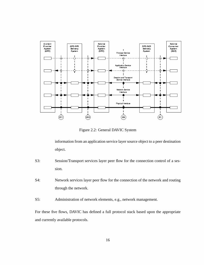
Figure2.2: GeneralDAVIC System
informationfrom anapplicationservicelayersourceobjectto apeerdestination
object.
S3: Session/Transportserviceslayerpeerflow for theconnectioncontrolof a ses-
sion.
S4: Network serviceslayerpeerflow for theconnectionof thenetwork androuting
throughthenetwork.
S5: Administrationof network elements,e.g.,network management.
For thesefive flows, DAVIC hasdefineda full protocolstackbaseduponthe appropriate
andcurrentlyavailableprotocols.
16
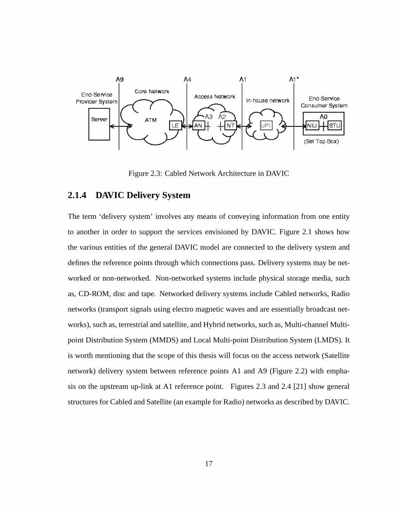
Figure2.3: CabledNetwork Architecturein DAVIC
2.1.4 DAVIC Delivery System
The term ‘delivery system’involvesany meansof conveying informationfrom oneentity
to anotherin order to supportthe servicesenvisionedby DAVIC. Figure2.1 shows how
thevariousentitiesof thegeneralDAVIC modelareconnectedto thedelivery systemand
definesthereferencepointsthroughwhich connectionspass.Deliverysystemsmaybenet-
worked or non-networked. Non-networked systemsincludephysicalstoragemedia,such
as,CD-ROM, discandtape.Networkeddelivery systemsincludeCablednetworks,Radio
networks(transportsignalsusingelectromagneticwavesandareessentiallybroadcastnet-
works),suchas,terrestrialandsatellite,andHybrid networks,suchas,Multi-channelMulti-
point DistributionSystem(MMDS) andLocalMulti-point DistributionSystem(LMDS). It
is worth mentioningthatthescopeof this thesiswill focuson theaccessnetwork (Satellite
network) delivery systembetweenreferencepointsA1 andA9 (Figure2.2) with empha-
sison theupstreamup-link at A1 referencepoint. Figures2.3 and2.4 [21] show general
structuresfor CabledandSatellite(anexamplefor Radio)networksasdescribedby DAVIC.
17
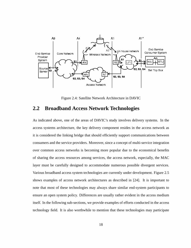
Figure2.4: SatelliteNetwork Architecturein DAVIC
2.2 BroadbandAccessNetwork Technologies
As indicatedabove, oneof the areasof DAVIC’s study involvesdelivery systems.In the
accesssystemsarchitecture,the key delivery componentresidesin the accessnetwork as
it is consideredthe linking bridgethatshouldefficiently supportcommunicationsbetween
consumersandtheserviceproviders.Moreover, sinceaconceptof multi-serviceintegration
over commonaccessnetworks is becomingmorepopulardue to the economicalbenefits
of sharingthe accessresourcesamongservices,the accessnetwork, especially, the MAC
layer must be carefully designedto accommodatenumerouspossibledivergent services.
Variousbroadbandaccesssystemtechnologiesarecurrentlyunderdevelopment.Figure2.5
shows examplesof accessnetwork architecturesas describedin [24]. It is importantto
notethat mostof thesetechnologiesmay alwayssharesimilar end-systemparticipantsto
ensureanopensystempolicy. Dif ferencesareusuallyratherevident in theaccessmedium
itself. In thefollowing sub-sections,weprovideexamplesof effortsconductedin theaccess
technologyfield. It is alsoworthwhile to mentionthat thesetechnologiesmay participate
18

AccessNode
AccessNode
AccessNode
AccessNode
AccessNode
AccessNode
FTTH
xDSL
MM DS/LMDS
HFC
Satelli teFTTC/VDSL
Metall ic
Metall ic
Optical Fiber
ONU
Optical Fiber
Optical Spli tter
ONU
ONU
ONU
ONU
Optical Fiber
ONU
CoaxialCable
Satelli te
Metall ic (Upstream controlline)
Optical FiberBase
Figure2.5: Examplesof AccessNetwork Architectures
19

Figure2.6: DOCSISGeneralConfiguration
in implementinga (completeor partial)DAVIC compliantsystem,which is not necessarily
developedby theorganizationitself.
2.2.1 CableNetworks
TheDataOverCableSystemInterfaceSpecification(DOCSIS)[9], [10] wasintroducedfor
cableoperatorsin deploying high-speeddatacommunicationssystemson cabletelevision.
It describesterminalstructuresanddatainterfacesthatwill provide betterperformanceon
cablenetworks. Subscribersaccessthe network througha CableModem(CM) andtheir
transmissionsarerealizedat thehead-endby aCableModemTerminationSystem(CMTS).
A generalconfigurationfor the DOCSISsystemis depictedin Figure2.6 [10]. The envi-
sionedservicesrely on efficient bi-directionaltransferof datatraffic over anall-coaxialor
hybrid-fiber/coaxcablenetworkorganizedin a tree-and-branch [9] architecture.Thesystem
usesupstream(CM to CMTS direction) frequenciesbetween5-30 MHz anddownstream
(CMTS to CM) frequencieswith a lower edgebetween50 and54 MHz andanupperedge
rangingfrom 300to 860MHz. Signalsmaybetransmittedatashighas10-15Mb/s. DOC-
SIS 1.1 [10] wasrecentlyreleasedto complementthe former DOCSIS1.0 [9]. DOCSIS
1.0only supportedstaticnetwork connectionsinitiatedduringsubscriberregistration(when
20

usersturn terminalson). DOCSIS1.1ontheotherhand,introducedadynamicdimensionto
thespecificationby definingdynamicservices.Dynamicservicesenablechangingattributes
of existing connectionsaswell asestablishingnew connectionsduringterminaloperation.
DOCSIS1.1 alsoenvisionedtheuseof somedifferentiatedschedulingservices.However,
specificcategoriesarenotyetcompletelystandardized.WehaveconsideredtheDOCSISas
a candidatetowardsdevelopmentof anefficient satelliteMAC. Detailson suchprocedure
andon theDOCSISMAC specificationitself will bepresentedin thenext chapter.
2.2.2 Digital SubscriberLine
Digital SubscriberLine (DSL) [11] offersbroadbandservicesoverspectrumbandsbeyond
the4kHz voicechannelsof twistedpairs.In thepast,bandwidthallocatedby thetelephone
company switch to voice calls limited the bandwidthof the voice modem. DSL technol-
ogy revealedthe capabilityof phonelines of carryingvery high dataratesif the narrow
bandswitchescanbeavoided. AsymmetricDigital SubscriberLine (ADSL) is oneof the
currentdevelopedDSL systems.It definesan asymmetrictransmissionsystemin which
downstreamsignalsusethebandwidthof severalhundredkb/srequiredfor Internetaccess
or several hundredMb/s requiredfor video transmission,while the upstreamusesband-
width sufficient for servicecontrolsignalswith lower initial investmentin facilities.ADSL
is capableof transmissionin a rangeof severalhundredmetersto severalkilometers.The
latestDSL systemis Very high bit-rateDigital SubscriberLine (VDSL) [12]. It is a high
bit-rateversionof ADSL that offers downstreamsignalsup to 30 Mb/s. However, dueto
thefactthatits transmissionis limited to lessthan1.5kilometersthereis a restrictionon its
applications.
21

2.2.3 Fiber to the Home
Fiber to theHome(FTTH) [14] is a fully opticalnetwork from theserviceprovider to the
consumer. Theopticalmultiplexedsignalis broughtto a splitter in thevicinity of a group
of customers.Thereareoptical splittersof differentratios,but themosttypical ratio used
is 1 to 16. This meansthat themultiplexedsignalis split to 16 differenthouseholds.Since
the optical signalhasto be convertedto electricalat the customer’s premises,an Optical
Network Unit (ONU) hasto be installedat the end of the network. Becausethe ONU
areexpensive, it hasbeensuggestedthat the resourcesof a singleONU shouldbe shared
amongseveralcustomers.Figure2.5 suggestswhat theFTTH accessnetwork might look
like. Applicationsof optical fibers result in fewer restrictionson transmissiondistances
and bandwidthsfor future serviceprovisioning. If we can achieve cost-effective optical
components,it maybeconsideredanidealline-feedaccesssystem[24].
2.2.4 BroadbandWir elessAccess
BroadbandWirelessAccess(BWA) is a wirelesssystemdesignedto deliver data,voice
andvideo with low delay. In BWA, multimediaservicesareprovided by basestationsto
businessor homenetworks in a star topology. As larger chunks(on the orderof 1 GHz)
of microwave andmillimeter wave spectrumarebecomingavailable,BWA becomesmore
liable for deployment in several regions. Most of the BWA frequency allocationsare in
the 24, 28, 31 or 40 GHz bandsandhave the capability to deliver dataratesin the tens
of Mb/s range. It shouldbe mentionedthatBWA is differentfrom the traditionalcellular
systemin two significantaspects.Firstly, BWA assumesfixedterminalsandthusdoesnot
supportmobility and the associatedcomplexity due to hand-over and fading. Secondly,
BWA operatesat high frequency, which limits the cell size [13]. The IEEE 802.16task
22

groupwasrecentlyformedto develop802standardsfor BWA.
2.2.5 Multi-channel Multi-point Distrib ution System
A typicalMulti-channelMulti-point DistributionSystem(MMDS) receivesscrambledsatel-
lite or cableTV signalsatacentrallocation.Thecentralstationthende-scrambles,digitizes,
multiplexes,andre-transmitsthereceivedsignalsby specialtransmitters(SHF).TheSuper
High Frequency (SHF, typically in GHz) transmittersthendistributethesignalsthroughout
thecoveragearea.Antennasinstalledon subscribers’roofs thenwill receive thesesignals
anddistribute themwithin the homeor building throughcoaxialcableinto a set-topbox
locatednearthetelevision. MMDS configurationis shown in Figure2.5.
Onemajorlimiting characteristicof wirelesscablesystemsis therequirementof line-of-
sight(LOS) transmission.Suchconstraintinducesa crucialdecisionon thelocationsof the
tranceivers.A preferablelocationwouldbeamountainpeak,with ahighangleof elevation
andfew obstaclesthatblock thesignal[25]. MMDS typically operatesin frequency bands
of lessthan 10 GHz, whereasPoint-to-Multi-point wirelesscommunicationssystemsfor
multimediabroadbandaccessservicescalled Local (L)MDS operatein millimeter-wave
frequency bandsover10GHz.
2.2.6 SatelliteAccess
Satellitecommunicationsystemscanoffer two-way interactive broadbandmultimediaser-
vicesoverwiderregionsthanall previouslydescribedtechnologiesdueto thenaturalbroad-
castcapability. They have theadvantageof possiblequicker deploymentin comparisonto
line-feedsystems,especially, in regionswith minimum infrastructures.They alsoprovide
line-of-sightadvantagesovermobilenetworks,especially, in crowdedregionswheresignal
23

blockingof wirelesstransmissionsis inevitable.Moredetailsaboutsatellitesystemswill be
presentedin thenext section.
2.3 BroadbandSatelliteSystems
In this section,we focuson presentingvarioussystemsdeployed for interactive services
over satellitenetworks andhighlight their drawbacks. We thenrevert to discussthe open
issuesin thefield with emphasison thedevelopmentof anefficientMAC layer.
2.3.1 Brief History
Satellitetechnologydatesbackto asearly as1947whenArthur C Clarke proposedGeo-
stationaryEarthOrbit (GEO)Satellites.Thefirst satellitelaunchedthoughwasa low earth
orbit known asSputnikdevelopedby the Russiansin 1957. The successof Sputniksig-
naledthebeginningof anew erain telecommunicationscharacterizedby globalworldwide
coverage. In 1965,Early Bird (akaIntelsatI) beganthe eraof commercialGEO satellite
communications.Afterwards,GEOsatelliteservicesstartedto spreadrapidly to provideIn-
ternationalaswell asRegionaltelephoneservicesoverwideareas.Currently, GEOsatellite
applicationsarevery popularin theTV broadcastingindustry, e.g.,Directv, PrimeStar, etc.
Low EarthOrbit (LEO) satellitesystemsarealsobecomingmorepopularwith Orbcomm
(1998),GlobalStar(2000),andICO-Global(2002).
Onthecourseof satellitedevelopment,complexity of equipmenthaschangeddrastically
from 34 kg, 240 telephonecircuits in the 1965Early Bird to 3000kg, 8 - 15 kW power,
1,200kg payloadin a year2000large GEOindicatingthehugeinvestmentsdedicatedfor
thesatelliteindustry. It is reportedthatexpectedrevenuesfrom all satellitecommunications
24

servicesshouldreach$75billion by 2005[26].
2.3.2 Interacti veBroadbandSatelliteSystems
Satellitesarecurrentlymainly usedfor TV andvoicecommunicationsworldwide. As the
most attractingfeatureof satellite is its naturalbroadcasting,video servicesby satellite
earned$17Billion in 1998.Hence,Wall StreetJournalcalledDirectBroadcastSatelliteTV
theGreatestTechnologyDevelopmentof theCentury[27]. Howeverasusers’demandsfor
multimediaInternet-basedservicesincrease,satellitetechnologyis challengedto enhance
itscapabilitiesby introducingauserinteractiondimensionto its structure.Satellitenetworks
operationwill no longerbeconfinedto a videoprovider broadcastingits datato customers.
Userswill have to be able to transmitdatathemselvesfor satelliteoperatorsto have any
chanceto survive in a highly competitive telecommunicationsmarket. As a matterof fact,
communicationssatelliteshave beenusedin theInternetfrom thebeginning,whereoneof
the first global networksusingthe Internetprotocolswasthe Atlantic SAT-NET intercon-
nectingtheARPANET with researchnetworksin Europein theyears1979-1985.However,
thescopeof futuresatellitenetworksin orderto sustainits establishedsuccessmustsurpass
just interconnectingpurposes.In thefollowing sub-sections,wepresentexamplesof differ-
entefforts to constructan interactive satellitesystem.We alsopoint out thedrawbacksof
eachsystemandhow they areavoidedunderthescopeof ourwork.
2.3.2.1 Interacti veDir ect BroadcastSatellite
A network configurationdescribedin [27] proposesa forward channelsuppliedby Direct
BroadcastSatellite(DBS). The returnlink to a server is provided by someothernetwork
(telephone,separatesatellitechannel,etc.) in order to achieve interactive datadevices.
25
Client
Client
STB
Return LinksISP
STB
Direct BroadcastSatelli te
Server
Server
MasterStation
ForwardLinks
Figure2.7: An IDBS SatelliteNetwork Configuration
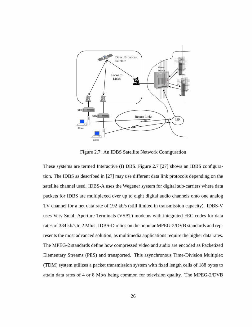
ThesesystemsaretermedInteractive (I) DBS. Figure2.7 [27] shows an IDBS configura-
tion. TheIDBS asdescribedin [27] mayusedifferentdatalink protocolsdependingon the
satellitechannelused.IDBS-A usestheWegenersystemfor digital sub-carrierswheredata
packetsfor IDBS aremultiplexedover up to eight digital audiochannelsonto oneanalog
TV channelfor a netdatarateof 192kb/s(still limited in transmissioncapacity).IDBS-V
usesVery Small ApertureTerminals(VSAT) modemswith integratedFEC codesfor data
ratesof 384kb/sto 2 Mb/s. IDBS-D reliesonthepopularMPEG-2/DVB standardsandrep-
resentsthemostadvancedsolution,asmultimediaapplicationsrequirethehigherdatarates.
TheMPEG-2standardsdefinehow compressedvideoandaudioareencodedasPacketized
ElementaryStreams(PES)and transported.This asynchronousTime-Division Multiplex
(TDM) systemutilizesa packet transmissionsystemwith fixedlengthcellsof 188bytesto
attaindataratesof 4 or 8 Mb/s beingcommonfor television quality. The MPEG-2/DVB
26

protocolarchitecturecanbebrokendown into threelevels;Physicallayerdefinedby EBU-
DVB documents[28]. Thedatalink providestransportover 188byteslong packets. Level
threeprovidesadaptationlayers.More detailson MPEG-2andDVB maybefound in [6],
and[7], [8] respectively.
It is notedthat IDBS assumesanasymmetricalnetwork accessconfigurationthatenvi-
sionsa separatenetwork for thereturnlink; usuallyis a terrestrialnetwork. Ratesattained
on this returnlink aremuchlower thantheforwardlink. Suchaconfigurationmightappear
relevant for web browsing like applications;especiallythat measurementsof typical web
sessionsanduserbehavior show a ratio of about10:1 to 20:1 betweenincomingandout-
goingdatastreams.However, underthepressureof users’demandsfor serviceintegration,
theallocatedbandwidthwill neverbesufficient to deploy somekey servicessuchasIP tele-
phony or videoconferencing,etc. Moreover, usingterrestrialnetworkswith its equipment
andfacilities for returnlinks, yet addsa new playerto a satelliteaccesssystem.This will
resultin highercostsif comparedto systemsthatintegratetheforwardandreturnpathsover
a sharedmediumunderthesameprovider. It is alsoworth mentioningthat recentlyIDBS
hastried to useseparatesatellitechannelsfor thereturnlink. However, suchefforts arenot
yet standardized.
2.3.2.2 TR34.1SATATM
Basedondemandfrom theindustry, theCommunicationsandInteroperabilitySection(CIS)
of the TelecommunicationsIndustryAssociation(TIA) satellitecommunicationsdivision
hasstartedthis standardizationprocess.TR34.1,thestandardscommitteefor CIS, hasde-
finedasetof satellitebasedATM [29] network architecturesfor futurephysicallayerspec-
ification. The architecturesdefinedby TR34.1are presentedin [30] andcanbe broadly
27

groupedinto two categories;satelliteATM (SATATM) architecturesfor transparentsatel-
lites, andSATATM architecturesfor satelliteswith on-boardswitches.In orderto provide
ATM andInternetservicesat requiredQuality of Service(QoS)levelsin a very bandwidth
efficientmanner, theTR34.1considersaDemandAssignedMultiple Access(DAMA) satel-
lite network asanidealplatformto respondto expectedvariablebandwidthdemands.One
suchnetwork is theCOMSAT Linkway 2000wide areanetworking andswitchingsystem
thatprovidesaccessandtransportfor packet switchedservices(ATM, IP/LAN, andFrame
relay),andcircuit switchedservices(ISDN andSignalingsystemNo. 7) [30]. It provides
a full-meshmulti-servicesatellitenetwork with a multi-frequency Time Division Multiple
Access(TDMA) [31] satelliteair-interfaceandunifiedframe,cell, andcircuit modetrans-
port services.
ATM packet sizeof 48 byteswasprimarily chosento specificallycarry voice packets
rangingbetween32 and64 kb/swith requiredquality of service.However, with the inva-
sion of multimediaservices,especially, video with variablelengthpackets,ATM packets
will not necessarilyremainthemostefficient transportsystemfrom theutilization point of
view. Sincehigherswitchingspeedsarefeasibledueto fasterprocessingcapabilities,sys-
temswith ratherlongeryetstill fixedsizepacketswill achievetherequiredqualityof service
with minimumoverhead.Moreover, ATM is currentlyevenbeingchallengedby non-fixed
packetssystemssuchasintegratedanddifferentialservicesof theInternetEngineeringTask
Force(IETF). As a result,wefind thatnewly deployedsystemsshouldbereluctantto com-
mit to aspecifictechnology. To succeedin achieving anopensystem,thedesignof aflexible
systemwith anindependentprotocol(SAT-MAC) thatallows convergencefor ATM or any
otherupperlayerprotocolwheneverneededis preferred.
28

2.3.3 SatelliteChallenges
While satellitenetworksindeedpromiseto becomewidely deployedasaccessnetworksfor
interactive residentialbroadbandservices,yet a lot of openissuesmuststill be addressed
beforesatelliteachievestheanticipatedsuccess.Oneof themostcommonresearchissues
focusesondevelopingextensionsto TCPin orderto overcometheslow startproblemunder
the long delayencounteredby satellitesystems.Antennatechnologyis alsoexperiencing
continuousdevelopmentsin orderto producerobustcost-effective terminals.Moreover, in
orderto respondto theeffectsof interferenceandfadingof thesatellitemedium,powerful
FECcodingalgorithmsaredesirable.Otheropenissuesincludeon-boardprocessing,beam
switching,protocolsuites,etc.
One of the most importantstudiesinvolves developmentof an efficient air-interface
MAC layerin termsof utilizationaswell ascomplexity. It shouldbenotedthatmostsatellite
studiesconductedin this domainup to this point usually involved the downstream(from
providersto customers)andhow to encodedataover the broadcastchannel.This issueis
nearlysettledwith advancementsin MPEG-2technologies.However, with the increasing
users’demandsfor interactive services,the challengeswitchestowardsthe capabilityof
multiplexing the maximumnumberof usersefficiently over smallerbandwidthswithout
affectingtheQualityof Service(QoS).Thetraffic patternoverdownstreamsatellitechannels
canalwaysbeassumedto achievearatherhighutilizationasaresultof consistentbroadcast
transmissionof datafrom a centralbasestationto variouscustomers.On the otherhand,
upstreamtransmissionsrepresenta distributed system. With customers’behavior being
lessconsistentas well, the burdenon the return link capabilitiesincreasesand requires
standardization.This triggeredthe necessityof developingan efficient MAC layer at the
air-interfaceterminalin theupstreamdirectionin orderto respondto thechallenge.
29

In this thesis,we proposea MAC architecturethat aimsto answerthe above require-
ments.Thescopeof thedevelopedMAC emphasizesonintroducinganew accesstechnique
with minimumdelayandhigh utilizationaswell asa novel distributedschedulingarchitec-
ture to minimize systemcomplexity. The integral functionality of both constituentswill
employ a DynamicCapacityallocation(DCA) approachto dynamicallyassignresources.
Completesystemdescriptionwill be presentedin the next chapter. In the following sub-
sections,we will presenta brief survey on both the MAC accesstechniquesanddifferent
schedulingstructuresin satellitesystems.Weshouldalsopoint out thatotherissuesrelated
to the MAC layer suchasschedulingalgorithms,admissioncontrol anduserparameters
controlareoutof thescopeof this thesis.
2.4 MAC AccessTechniques
MAC protocolsaredesignedto enablecommunicatingstationsat diverselocationsto reg-
ulatetransmissionsof their packetsandmanagenetwork bandwidthin orderto utilize the
network resourcesasefficiently aspossible.If theindividualtraffic loadperconnectionwas
high and the interconnectionpatternswerestatic,a fixed capacityallocationwould have
beenapplicable.Unfortunately, traffic in residentialserviceapplicationssupportingmulti-
mediais ratherburstyandusers’behavior is non-consistent.Hence,capacityallocationhas
to bemoredynamicto copewith thereal-timetraffic demandssothatsatelliteresourcesmay
efficiently besharedby a largepopulationof earth-terminals.Many accesstechniqueshave
contendedto leadthatrole [32], [33]. In this section,wedescribesomeof thesetechniques
anddiscusstheir suitability in satelliteaccessnetworks.
30

2.4.1 Fixed Assignment
In the fixed-assignmentmultiple accesstechnique,the allocationof channelbandwidthto
a station is a static assignmentand independentof other stations’activities (i.e., circuit
switching).Examplesof fixedassignmenttechniquesareFrequency, Timeor CodeDivision
Multiple Access(FDMA, TDMA or CDMA) [31]. Fixed assignmenthasthe advantage
of beingsimpleandwith minimum delay. However, with bursty traffic, fixed assignment
resultsin a hugewastein bandwidthresourcesrenderingvery low utilization. Moreover,
with channelsbeingcompletelydevotedto singleusersover extendedtime periods,fixed
assignmentallowslimited numberof usersthatcansimultaneouslyaccessthemediumwith
therequiredqualityof service.
2.4.2 RandomAccess
Randomaccessallows terminalsto instantlytransmittheir datapacketsassoonasthey ar-
rive, independentof otherstations. As it representsa distributedsystem,datapacketsof
variousterminalsaredestroyed from time to time dueto possiblecollisions. Examplesof
randomaccesstechniquesincludepureALOHA andslottedALOHA [29] proposedfor ear-
lier stagesof satellitecommunications.Randomaccesshastheadvantageof beingsimple.
It alsorequiresnosetupphase,whichotherschemes,suchas,reservationmightuse.At low
load,retransmission(dueto possiblecollisions)is negligible, whichoffersterminalsinstant
channelaccess.However, with increasingloads,collisionratesgrow exponentiallyandcon-
sequentpacketretransmissionbecomesnon-acceptable,especially, in real-timeapplications
andqualityof servicecannotbeguaranteed.It is worthwhileto mentionthatthemostinno-
vative randomaccessschemescanonly provide anupperboundof achievableutility in the
regionof 0.4-0.5.
31

2.4.3 DemandAssignment
Demandassignmentallows dynamicallocationof capacityon demandin responseto sta-
tion requests.Thealgorithmreservesbandwidthbasedon terminaldemandsandtherefore
rendershigh utility. Thereservationschemeitself might befixedor random.Examplesof
demandassignmenttechniquesincludePriority OrientedDemandAssignment(PODA) and
FIFO OrientedDemandAssignment(FODA) [32]. Demandassignmentis bestsuitedfor
jitter-tolerantqueueabletraffic. In spiteof its high utility, demandassignmentin satellite
environmentexperiencesinevitable setup (reservation) delaysof two roundtrips (around
500ms)addedto anotherroundtrip delayof datatransmissionfor a totalof threeroundtrip
delays.This is ratherunacceptablefor interactiveasymmetricreal-timeapplications,where
userscontinuouslyproduceshortcontrol commands,especially, given that randomaccess
canavoid suchdelaysunderlow loads.
2.4.4 CombinedTechniques
Multimedia traffic containsboth real-time(e.g.,voice andvideo) and jitter-tolerant(e.g.,
dataandgraphics)andrequiresa combinedtechniqueto be efficiently transported.Com-
bined techniquesaim to provide fast accessfor low load conditionsandshortmessages,
suchas, inquiry messagesin interactive datasessions,and to attain high utility of satel-
lite resourcesat high traffic load. In the following sub-sections,we provide examplesfor
combinedtechniques.
2.4.4.1 CombinedRandom/Reservation
A random/reservationschemeachieveslow delayatlow loadswith highutility of reservation
schemes.Bandwidthmaybecategorizedinto reservedandunreservedslots. Jitter-tolerant
32

traffic maybeconveyedover both typesof slots. Real-timetraffic on theotherhand,only
usesreserved slots. Sincesatelliteprovidersusespotbeamsto achieve channelreuse,the
scheduleratthemastercontrolis requiredtomonitorunreservedchannelsandreliablydetect
collisionsasterminalswill not beableto detectcollisionswith simultaneoustransmissions
on otherbeams.This will leadto very longcollision resolutionperiods;i.e.,a terminalwill
not be able to detecta collision beforetwo roundtripdelaysand is forcedto remainidle
within that period. In caseof a singlebeam,terminalscould be able to detectcollisions
instantaneouslyandthereforemightattemptretransmissionin thenext unreservedslot.
2.4.4.2 CombinedFree/DemandAssignmentMultiple Access
Contentionfreeprotocolscancontrol theworst delayin caseof real time applications.In
combineddemandassignmentwith fixed assignmentor with free assignment,unreserved
slotsareeitherfixedor freely assigned.TheCombinedFreeDemandAssignmentMultiple
Access(CFDAMA) providesbetterperformancedueto its dynamicfeature.By combining
freeassignmentwith demandassignment,CFDAMA protocoloffersmuchshorterdelaysat
low andmediumtraffic loads,while maintainingthe high channelutility of DAMA tech-
niques. Reservation in theseschemesmay be pre-assignedrequestslots,piggybackingor
any otherspecialalgorithm.A studyin [33], [34] showssuperiorityof CFDAMA overother
accesstechniquesin satelliteenvironments.CFDAMA mightbeevenenhancedby allowing
terminalsto reserveaheadof timebasedonaprediction.If thepredictionalgorithmhasac-
ceptableaccuracy, thenew enhancedCFDAMA will evenprovide betterperformancewith
lowerdelays.Detailson thatschemeandthedevisedprotocolbehavior arepresentedin the
next chapter.
33

2.5 SchedulingStructur es
Schedulingis mandatoryto complementanefficient accesstechniqueto achieve high per-
formance.It determineshow themastercontrolstationdistributesavailablecapacityondif-
ferentterminalsbasedon a specialalgorithm. Thesimplestschedulingalgorithmsarefirst
comefirst servedandroundrobin. However, schedulingalgorithmsareout of thescopeof
this thesis.In DynamicCapacityAllocation (DCA), theschedulermustdynamicallyassign
slotsto variousterminalseachtime frame(24 ms) . Hence,it requiresa lot of computing
anddataprocessing.Accordingly, schedulingstructureswith lesscomplexity arealways
desirable.Thissectiondescribestwo possibleschedulingstructures.
2.5.1 Centralized Scheduling
In centralizedscheduling,the schedulersuperviseseachandevery connectionwithin the
network. As a resultof serviceintegration,eachterminalis expectedto continuouslypro-
ducenumeroussimultaneousconnections.Thiswill overloadtheschedulerwith long look-
up tablesandwill leadto longprocessingdelays.
2.5.2 Centralized/Distributed Scheduling
As mentionedabove, the scheduleris obliged to control a large numberof connections
over a hugepopulation. In order to reducethe complexity, schedulersmay be structured
into two levelsof scheduling;amacrolevel responsiblefor handlingtheaggregaterequests
of eachterminalanda micro level, whereeachterminaldistributesgrantedcapacityover
local connections.While the mastercontrol stationperformsmacrolevel scheduling,it
is the terminalsthemselves that handlemicro scheduling. As the mastercontrol station
34

then dealsonly with total terminal demandsand not single connections,the scheduling
processingduty becomesdistributedrenderinglower complexity andminimumprocessing
delays.However, theoverall bandwidthcontrolstill residesat themastercontrolstationin
a centralizedmanner. Full detailson thatschedulingstructurewill bediscussedin thenext
chapter.
2.6 Summary
In thischapter, wehave indicatedtheimportanceof broadbandaccessin futuretelecommu-
nicationssystems.Accordingly, we highlightedthestructure,objectivesandachievements
of DAVIC asoneof themostactive standardsbodiesin thefield. We have alsodiscussed
variouscompetingtechnologiescontendingfor theaccessnetwork role andhencepointed
out the essenceof developmentof efficient satellitenetworks to achieve simpleandcost-
effectiveglobalcoverage.Consequently, wepresentedtheboundingfactorsthatlimit direct
successfuldeploymentof broadbandinteractivesatelliteaccessandfocusedour intereston
developmentof an efficient MAC layer at the air-interfaceterminalsto achieve maximum
utilizationandminimumdelay.
In thenext chapter, we will discussthroughlya proposedMAC architectureto address
theaboverequirements.Weshow systemstructures,behavior sequences,accesstechniques
andschedulingarchitectures.
35

Chapter 3
BroadbandSatelliteAccess
Broadbandsatelliteaccessis anaccesssystemwith a satellitesegmentrepresentingits ac-
cessnetwork. It addressesthesamemarketsandservicesasotheraccesstechnologiessuch
as, wireless,copper, cable,etc. As indicatedin Chapter2, most servicesdeployed over
currentconventionalsatellitesystemsareonly one-way andusually rely on a phoneline
for the returnpath (upstream)to provide interactive features. Any failuresin the public
network will directly terminateany communicationpossibility. In broadbandsatelliteac-
cess,two-way interactivemultimediaservicesaresupportedoversharedbandwidth.In this
chapter, we describea proposedbroadbandsatelliteaccesssystem.We show its configura-
tion structure,constituentsandproposedprotocolstacks.We emphasizeon theMAC layer
specificationdueto its critical role in systemimplementation.Themainscopeof thedevel-
opedMAC includesdynamiccapacityallocationundera novel accesstechniquebasedon
an enhancedCFDAMA andsimpleschedulingstructuresaswell asthe protocolbehavior
specification.
36

BackboneInternet
Subscriber
VoD Service Provider
Subscriber
Satellite AccessNetwork
MCS
Figure3.1: GeneralConfigurationof aBroadbandSatelliteAccessSystem
3.1 BroadbandSatelliteAccessConfiguration
Figure 3.1 shows the generalconfigurationof a broadbandsatelliteaccesssystem. The
figure indicatesthat via the satellite,subscribersmay accessa VoD serviceor an Internet
backboneforming two accessdomains.Within eachaccessdomain,aserviceprovider ren-
dersits applicationservicesto a groupof subscribers.A MasterControl Station(MCS)
supervisedby thesatelliteprovider is necessaryin orderto regulatemediumaccessamong
subscriberswithin thesamedomainaswell asacrossdifferentdomains.This is oneof the
maindifferencesthatdistinguishsatelliteaccessfrom othertechnologies.In thesetechnolo-
gies, the serviceandnetwork providersarecommonlysupervisedandusuallyphysically
locatedat thesamestation.On theotherhandin satellitesystems,theserviceprovider and
the network provider (satellite)are separate.Propercoordinationandsignalingbetween
bothprovidersis thereforeessentialto guaranteesuccessfulaccess.Thiscanbeachievedby
implementinga carefullydesignedMAC layer. TheMAC layerarchitecturemustbecon-
figuredto dynamicallymultiplex themaximumnumberof terminalswith highestpossible
utilizationandoptimumuseof satelliteresourcesover thesatellitenetwork.
In general,satellitecommunicationsis onetypeof BWA (BroadbandWirelessAccess).
37

Downstream Direction
Upstream Direction
STS
STS
MCS
MCS-ULUS-DL
DS-UL
US-DL
MCS-DL
DS-DL
US-UL
MCS-DL
BTS
Figure3.2: BSA SingleDomainBlock Model
However, the IEEE BWA groupexcludessatellitefrom their specifications.Our proposed
systemis part of a generalBroadbandSatelliteAccess(BSA). However, from this point
andthroughouttherestof this thesis,we will usethetermBSA to specificallyrefer to our
proposedbroadbandsatelliteaccesssystem.
3.2 BSA System
Figure3.2 depictsthe proposedblock modelfor the BSA system.The systemconsistsof
threemainstations:
� BaseTransceiver Station(BTS): It representsthegateway to thebackbonenetwork.
Subscribers’informationandregistrationfiles to bedownloadedduringSTSinitial-
izationarelocatedthere.
� SubscriberTransceiverStation(STS):It is connectedto theuserpremisesequipment.
38

It representsthe air-interfaceterminal. The interfaceto the userequipmentis stan-
dardizedto satisfyrequirementsof anopensystem.
� MasterControlStation(MCS):Regulatestheaccessto thesatellitemedium.
It is worthwhile to mentionthat we adoptsimilar terminology, asBWA, IEEE 802.16for
BTSandSTS,howeverwemustagainhighlight thattheMCSis uniqueto satellitesystems.
Theconfigurationshown is basedonaPoint-to-Multi-Pointstructureto form astartopology
for only oneaccessdomain.Multiple domainshowever, maycoexist in theaccessnetwork.
Upstreamdirectioninvolvesdatatransmissionsfrom STSto theBTS.Downstreamdirection
involvesdatatransmissionsfrom theBTS to STS.Thesatellitecanhave non-regenerative
transpondersandactsasa bentpipe whereup-link transmittedsignalsareamplified, re-
transmittedandswitchedat RF onto thecorrespondingdown-link beams.As indicatedin
thefigure, traffic andcontrol informationmaybe transmittedover threedifferentpossible
paths:
1. STScontrolandtraffic informationtransmittedover theUS-UL (UpstreamUp-link)
areamplifiedandregeneratedby thesatelliteover theUS-DL (UpstreamDown-link)
wherethey canbereceivedby theBTSandMCS.
2. BTStraffic informationtransmittedovertheDS-UL (DownstreamUp-Link) is ampli-
fied,regeneratedandbroadcastby thesatelliteoverDS-DL (DownstreamDown-link)
to bereceivedby differentSTS
3. MCS control informationtransmittedover theMCS-UL (MCS Up-link) is amplified
and regeneratedby the satelliteover MCS-DL (MCS Down-link), whereit canbe
receivedby theBTS andSTS.
39

SAT MAC
IP
PHY
LLC
SNMP
TCP/UDP
PHY
DLC
Application
TCP/UDP
RSVPIP
PHY
DLC
Application
TCP/UDP
RSVP IP
Convergence
PHY
DLC
RSVP IP
PMD
LLC
TFTP
UDP
RSVPIP
SAT MAC
DHCPSNMP
Convergence
PHY
DLC
RSVPIP
PMD
LLC
SNMP
UDP
RSVP IP
SAT MAC
DHCPTFTP
CPESTSBTSProvider
SNMP: Simple Network Management Protocol.DHCP: Dynamic Host Configuration Protocol.TFTP: Trivial File Transfer Protocol.RSVP: The Reservation Protocol.DLC: Data Link Protocol.LLC: Logical Link Control.CPE: Customer Premises Equipment.
MCS
Figure3.3: OverallBSA StackStructure
3.3 BSA ProtocolStacks
Figure3.3depictstheoverallstackstructurefor aBSA system.Themainfocusof ourstudy
involvesthe interfacesto the satellitemediumat the air-interfaceterminal. Designof in-
terfacestowardstheserviceprovideranduserequipmentshouldusestandardizedprotocols
andareassumedto satisfytherequirementsof anopensystem.An opensystemfacilitates
massproductionof customerequipmentindependentof theaccesstechnologyused(cable,
wireless,satellite,etc.).As shown in thefigure,theBTSandSTSmayoperateasforwarding
agents(bridging or at the network level asin Figure3.3) andalsoasend-systems(hosts).
As hosts,the applicationlayer supportsa numberof protocols. SNMP (SimpleNetwork
andManagementProtocol)is responsiblefor network management.DHCP(DynamicHost
ConfigurationProtocol)andTFTP(Trivial File TransferProtocol)areusedduringSTSini-
tialization procedures.Figure3.4 shows a threedimensionalmodelfor the BTS andSTS
actingasforwardersat thenetwork layer. Thestackis dividedinto two planes.In thedata
plane,thefollowing layersmaybedefined:
� Upperlayers:TheproposedMAC is flexible andmayindependentlysupportInternet
40

Data Plane
Control Plane
RSVP
LLC
MAC TCDAV TC
DigitalAudio/Video(BTSonly)
Upper Layer
Physical Layer
DataInterface
ServiceInterface
Interface
MAC Mang.
Convergence
BSA MAC
Figure3.4: 3-DimensionalBSA StackModel with BTS andSTSactingasForwardersattheNetwork Layer
protocolor ATM services.We assumethatreal-timetraffic over theselayersmayby-
passtheLLC anddirectlyaccesstheMAC assupportingservicesmayacceptslightly
erroneouspacketsratherthanafford delaysresultingfrom retransmissions.
� ConvergenceLayer: It encapsulatesProtocolData Units (PDU) framing of upper
layersinto thenativeBSAMAC/PHYPDUandtranslatesupperlayerQoSparameters
into BSA MAC constructs.It alsomapsupperlayer’s addressesinto corresponding
BSA addresses.
� BSA MAC Layer: This is the main focusof our study. It guaranteesefficient data
transmissionoverthesatellitemedium.DetailsontheMAC layerarepresentedin the
next sections.
� SegmentationandRe-assembly:Thisprocessat theMAC TransmissionConvergence
(TC) sub-layeris responsiblefor segmentingvariablelengthMAC framesinto equal
lengthpacketsto be reassembledonceagainat theotherside. It is essentialin MF-
TDMA ascapacityallocationsby theschedulerat theMCSmaybedistributedovera
41

rangeof carrierfrequencies.Transmissionof MAC framesover fixedsizepacketsis
essentialto satisfyQoS[35].
Notethat in theBTS only, broadcastMPEG-2encodeddigital audio/videomaybypassthe
MAC protocollayeranddirectly accessthephysicallayer in thedownstreamasit usually
conveys distribution traffic anddoesnot needtheMAC accessfunctionalityusedwith up-
streamtransmissions1. In the control plane,the generalstructurecanbe summarizedinto
thefollowing layers:
� A Control Protocol: As an illustrative example,we assumethe IETF Reservation
ProtocolRSVP[36]. It is thecontrolprotocolusedfor resourcesreservation in IPv6
(IP thenext generation)[37]. In RSVP, datais forwardedto thedestinationacrossthe
pathdeterminedduringtheresourcesreservationphase.
� InterfaceLayer: It translatesRSVPcommandsinto local messagesthatwill beused
for the resourcereservation over the satellitelink. It containsthe dynamicservices
processaswell asadmissionandpolicy functionalities.
� MAC ManagementLayer: It is responsiblefor overallMAC layermanagement.Typ-
ical functionsincludesystemmanagementandSTSregistration.
� LLC Packaging:We encapsulateMAC managementmessagesin LLC packagingin
consistency with theDOCSISspecifications[9], [10].
1MPEG-2transmissionsover theupstreammustutilize theMAC accessfunctionality. All upstreamcon-nectionsdefinepoint-to-pointlinks betweenanSTSandthecorrespondingBTS.
42

3.4 BSA MAC Layer
As indicatedearlier, akey elementto thesuccessfuldeploymentof aBSA systemis thede-
velopmentof a suitableMAC protocol/techniqueto efficiently sharethesatelliteresources.
TheMAC Layershouldaddressthefollowing challenges:
1. Satellitemediumlongdelayandits resourceconstraint.
2. ExpectedburstyInternetandmultimediatraffic of envisionedservices.
3. QoSrequirementsfor real-timeandnon-real-timedataexpectedto be conveyed by
theBSA system.
Capacityof thedownstreamlinks maybeassumedto befixed,astheaggregatebroadcast
transmissionis consideredto have high loadandis rathersmooth(i.e., thepeak-to-average
ratio is closeto unity). Transmissionover theupstreamandMCS links is burstywith high
peak-to-averageratio and necessitatesan efficient MAC. The MAC must satisfy certain
delayboundsandattainmaximumutilizationatthesametime. As anillustrativeexample,in
thefollowing discussionswefocusononeaccessdomain.Weassumethatin aBSA system,
theSTScanonly communicatewith eachothervia theBTS. We shouldalsomentionthat
weconsiderInternet-basedupperlayersspecifically, IPv6andRSVPfor integratedservices.
However, wemustagainemphasizethatourdevelopedarchitectureis completelyconsistent
with otherupperlayersdependentondifferentialservices.
3.4.1 BSA MAC Ar chitecture
We have chosentheDOCSIS1.1RF-interface[10] specificationasour building block due
its popularity in addressingthe samerangeof servicesanticipatedover satellitenetworks
43

andwe alsoadopttheir messageterminology. However, ascableandsatellitemediarender
diversecharacteristicsaswell asdifferentconfigurations(with satellitesystemsemploying a
MCS),largemodificationsto theDOCSIS1.1infrastructureshouldbeintroducedto achieve
optimumperformanceover satellite.In thefollowing sub-sections,we presentvariousfea-
turesof our BSA MAC layer. We alsohighlight aswell asjustify thedifferenceswith the
DOCSIS1.1specification.
3.4.1.1 BSA Medium AccessScheme
Terminalsare assumedto deploy a Multiple Frequency Time Division Multiple Access
(MF-TDMA) [33] accessschemewidely usedin satellitecommunications.It offers sim-
ple connectivity, greatflexibility andcompatibility with digital transmission.Superiority
of MF-TDMA over FDMA/TDMA employedby DOCSISis attributedto a bettertrunking
efficiency dueto a largerpoolof availablephysicalchannels.In MF-TDMA, thebandwidth
is first dividedinto a numberof frequency bands.A streamof time slotsis recognizedover
eachfrequency band. A channelin MF-TDMA is definedby a time-frequency slot in a
two-dimensionalframeasshown in Figure3.5. All STSmayaccessthesetime-frequency
slotsin a sharedmanner. Capacityallocationin MF-TDMA canberepresentedby a time-
frequency map indicating the time-frequency slots assignedto eachterminal. Note also
asshown in the figure, that mini-slots in the time-framemapmight vary in the time-slot
sizesor the transmissionbandwidth. Sinceeachtime-slotmusthave a segmentationand
re-assembly(SAR) header, variationin slot sizessupportsthecapabilityof decreasingthe
resultingoverheadwhensmallerpoolsof physicalchannelsareallowed underlow loads.
Variationin transmissionbandwidthon theotherhand,givestheBSA systemtheflexibility
of supportingterminalswith variousmodemtransmissionratecapabilities.
44

time (t)
STS-9STS-7
STS-7STS-4Carrier f3
Carrier f4
Carrier f2STS-2 STS-1
Carrier f1STS-1 STS-3 STS-2
Carrier f6f6
STS-8
Carrier f5 STS-6 STS-10
Band-1
Band-2
Band-3
Figure3.5: MF-TDMA Structurein BSA
3.4.1.2 Dynamic Capacity Allocation
Traffic in residentialapplicationssupportingmultimediaserviceshasdifferent typeswith
diversecharacteristicsandis ratherburstyin nature.Hence,thecapacityallocationscheme
hasto becarefullychosento attainbetterperformance.Terminalswith real-timetraffic re-
questsatelliteresourcesinfrequentlybut with relatively highcapacityandastringenttiming
requirement.Accordingly, in BSA, we employ DynamicCapacityAllocation (DCA) for
assigningdatatraffic. In DCA, satelliteresourcesaredynamicallyallocatedto registered
terminalsdependingon therequest,scheduler’s status,priority, etc. DynamicCapacityAl-
location(DCA) will thereforegiveenoughflexibility to guaranteethatsatelliteresourcescan
beefficiently sharedby thelargestpossiblepopulationunderminimumpossiblebandwidth
requirements.SuccessfulDCA necessitatesthefollowing two complementaryfunctions:
45

AccessTechnique Randomaccesstechniquesbasedon ALOHA [29] wereinitially pro-
posedfor satellitesystems.ALOHA is contentionbasedwith low utility andenvisionedser-
viceswill not toleratedelaysaccompaniedwith retransmissionsdueto collisions. In BSA,
we proposeto usea CFDAMA-basedMAC accesstechniquefor dynamiccapacityalloca-
tion. CFDAMA [33] is a hybrid accesstechniquewhereun-requestedbandwidthis freely
allocatedto usersaccordingto a pre-determinedalgorithm. DOCSIS1.1 employs a hy-
brid reservation/contentionbasedaccesstechnique.As discussedin Section2.4,contention
degradesutilization anddelayperformancein satellitesystems.We have also discussed
CFDAMA superiorityin satellitenetworksover traditionaltechniquesin thatsection.
Furthermore,in BSA we proposean enhancedCFDAMA accesstechnique.By com-
bining predictionwith CFDAMA, betteraccessdelayperformancemay be achieved. In
thatscheme,STSutilize a predictionfunction in their demands.STSrequeststo theMCS
will not reflecttheir instantaneousneeds.Rather, anticipatedbandwidthaftertwo roundtrip
delayswill bedemanded.Moreover, freeassignmentby theMCScanbebasedonapredic-
tion of terminals’demandsandactivity. While thefirst approachpromisesfasteraccessfor
demandassignmenttraffic, thesecondapproachwould promotebetterutilization of freely
assignedtraffic. It is worthwhileto mentionthatwe only allow contentionin thebeginning
initialization proceduresasuserssignalto theMCSwhenturningon their terminals.
MCS Scheduling MCS areobligedto controla largenumberof connectionsovera huge
population. In order to reducethe MCS complexity, we have structuredtwo levels of
schedulingin our system;a macrolevel responsiblefor handlingthe aggregaterequests
of eachSTSterminalanda micro level whereeachterminaldistributesgrantedrequests
over local connections.While macrolevel schedulingis doneat the MCS, the terminals
themselves(STS)handlemicroscheduling.As theMCSdealsnow only with total terminal
46

demandsandnot singleconnections,the schedulingprocessingduty becomesdistributed.
Distributedschedulingachievesan MCS with lower complexity andminimum processing
delays.However, overallbandwidthcontrolstill residesat theMCSin acentralizedmanner.
To furtherdecreasevariablesprocessedby theMCS, connectionsbetweenanSTSandthe
MCS on theupstreamup-link maysimply bedefinedby only a limited numberof standard
servicecategories(real-timeandnon-real-timefor example)with minimumparametersper
category (requiredaveragebandwidthfor example).This meansthatthemaximumnumber
of logical connectionswith an STSthat the MCS hasto handleis alwaysboundedby the
numberof categoriesableto supportall upperlayerconnectionswithin thatSTS.This re-
lievestheMCSfrom theburdenof managingnumerousconnectionsperSTSwith minimum
informationto beprocessed.
3.4.1.3 Dynamic Services
In BSA, we adopttheDOCSIS1.1 conceptof dynamicservicesto supportQoS.QoSde-
finesparametersasdelay, throughput,jitter, etc. thatshouldbesustainedduringthelifetime
of a connection.Dynamicservicesallow terminalsto dynamicallyadd,modify or delete
connectionsbasedon upperlayerrequests.Eachconnectioncorrespondsto a singlediffer-
entiatedservicecategory. Basedon their QoSparameters,upperlayerconnectionswill be
categorizedinto localservicecategorieswith specificequivalentparametersvia a translator.
Requestswith theresultingparametersandconsequentnegotiationswill thenbeconveyed
throughdynamicserviceprocedures.Servicecategoriesarealsoproposedby DOCSIS1.1,
however, they arenot yet well-standardized.ThecurrentDOCSIS1.1 specificationrather
reliesonsingleconnectionsbetweenthesubscribersandtheequivalentMCS.
47

3.4.2 MAC Protocol
TheMAC protocolspecifiestheMAC layerbehavior anddefinesmessagesequencesacross
thesystem.A MAC Framedefinestheunit of informationexchangedbetweenMACentities.
MAC framesmaybeoneof thefollowing types:
� DataFrames:DataframesmaycarryanIP packetor avariablenumberof ATM cells.
� MAC SpecificFrames:SpecificframesmaybeRequestframesusedfor reservation
requestsor MAC managementframes,whichcarrytheMAC managementmessages.
MAC managementplaysa key role in theMAC protocoloperationasit controlsandman-
agesall theprotocolmainfunctions.Managementmessagesareencapsulatedin LLC infor-
mationframes,which in turnareencapsulatedwithin MAC framingin consistency with the
DOCSISspecifications.
3.4.2.1 MAC ManagementMessages
Thedifferentmanagementmessageschosencoincidewith DOCSIS1.1terminologyandare
describedasfollows:
� SYNC (Synchronization):A SYNCmessageis transmittedperiodicallyby theMCS.
STSuseit to establishMAC sub-layertiming. TheMCS broadcastsinsidethis mes-
sagethecurrentstateat transmissionof a clock insidetheMCS to offer timing refer-
ence.
� UCD (Up-link ChannelDescriptor):A UCD messageis transmittedperiodicallyby
the MCS. It definesthe characteristicsof possibleSTSup-link channelbandswith
similar characteristics.Typical descriptorswould includemini-slot size,symbolrate,
modulationtypeandotherphysicalparameters.
48

� MAP (Allocation Map): A MAP messageis regularly sentby the MCS in orderto
organizeandregulatebandwidthallocationsonupstreamup-links.Basedonschedul-
ing decisions,it describestime asa variablenumberof variable-lengthtransmitop-
portunitiesover a bandof frequencies.Opportunitiesinclude request,data, initial
maintenance(ranging),stationmaintenance(ranging),andregistration.
� RNG_REQ(RangingRequest):RNG_REQmessagesaretransmittedby an STSat
initialization andperiodicallyon requestfrom MCS to determinenetwork delayand
requestfor time,powerandfrequency adjustmentsoveracertainbandof frequencies
describedby acertainUCD.
� RNG_RSP(RangingResponse):A RNG_RSPmessagemustbe transmittedby the
MCS in responseto a received RNG_REQ.Typical carriedparameterswill include
timing andpoweradjustmentaswell asfrequency fine tuning.
� REG_REQ(RegistrationRequest):A REG_REQmessageis transmittedby anSTS
duringtheinitializationphase.It carriesSTSconfigurationparametersasdownloaded
from theBTS.Theseparametersareusedby theMCS in registeringtheSTSwith the
satellitenetwork.
� REG_RSP(RegistrationResponse):A REG_RSPmustbetransmittedby theMCSin
responseto REG_REQ.TheMCSmaymodify someof theREG_REQparametersin
theresponse.
� REG_ACK (RegistrationAcknowledgment):A REG_ACK messageis transmitted
by theSTSin responseto a REG_RSPfrom theMCS. It confirmsthereceptionand
acceptanceof theSTSto theQoSandotherregistrationparametersasreportedby the
MCS in theREG_RSP.
49

Power_On
STS
SYNC
RNG_RSP
INI_RNG_REQ
MAP
UCD
SYNC
SYNC
MAP
SYNC
DHCP_REQ (data)
DHCP_RSP (data)
TFTP_REQ (data)
TFTP_REQ (data)
REG_RSP
REG_REQ
REG_ACK
BTS MCS
Figure3.6: An Examplefor STSInitialization
3.4.2.2 Illustrati veExample for Protocol Operation
To illustratethefunctionalityof theMAC management,we presentthe following example
shown in Figure3.6to describeanSTSinitialization procedure:
As soonasan STSpowerson, it scansfor an appropriatedown-link channelandwill
acquiresynchronizationwith theMCS by receiving two consecutive SYNC messages.On
thesamedown-link channel,theSTSmustthenreceiveanappropriateUCD transmittedby
theMCS. An appropriateUCD definesa bandof channelswith similar physicalattributes
thatcoincidewith theSTScapabilities.Following that,a rangingprocessis thennecessary
for theSTSto performtiming, power andfrequency adjustments.TheSTSshouldusethe
first initial rangingopportunityover the first received MAP message.A randomback-off
algorithmis usedto resolvecollisions2. OncetheINI_RNG_REQ(Initial RangingRequest)2Note that contention-basedallocationsareallowed only whenterminalslog on to the satellitenetwork.
TheMCS cannotrecognizeinactive terminalsandallows themto join thenetwork over regularly transmittedinitial maintenanceopportunities.Probabilityof collisions is low becauseusersare lesslikely to log on atexactly thesamemoment.
50
transmissionis successfultheSTSis assignedatemporaryID in theRNG_RSPandany fur-
therranginginstructionswill berecognizedasopportunitiesassignedto thetemporaryID or
thestationID acquiredafterregistration.To obtainits IP addressaswell astheIP addressof
theconfigurationfile from theBTS(serviceprovider), theSTSmustestablishIP connectiv-
ity via DHCP. Usingthis informationtheSTScandownloadtherequiredparameterfile via
TFTP. DHCPandTFTPcommandsarecarriedasdataframesusingMCSallocationsto the
temporaryID. In caseany of thesetwo processesis delayedor non-successfulboththeMCS
andSTStimeoutandthetemporaryID will belost. Re-initializationof theSTSis required
in thatcase.SuccessfulDHCPandTFTPrendertheSTSimplicit registrationto theserver
network. STSmustalsoperforma registrationprocedurewith the MCS to gainaccessto
thesatellitenetwork. Theregistrationshouldbebasedontheparametersof thedownloaded
file, which definesSTSmodemcapabilities,allowedbandwidth,thecorrespondingaccess
domain,policy data,etc. Uponregistrationsuccess,STSis givena stationID identifiedby
theBTSandis givenauthorityto exchangedatatraffic with theserviceprovider.
It is worthmentioningthattheMCSalwaysmonitorsregisteredSTSdatatransmissions
andtakesnecessaryproceedings(stationmaintenance)to maintainacceptableSTSranging
parameters.
3.4.3 Bandwidth Allocation and Scheduling
Allocationsandtransmissionopportunitiesoverfuturetimeframesrelyondynamiccapacity
allocation(DCA) assumingtheenhancedCFDAMA techniqueandaredefinedby theMAP
managementmessagesregularlytransmittedby theMCS.In thissub-section,wepresentthe
differentallocationopportunitiesin BSA andshow theSTSandMCS block structuresfor
DCA.
51

3.4.3.1 TransmissionOpportunities
A MAP messageconveying allocationdescriptionis constitutedof a groupof consecutive
MAP elements.A MAP elementis composedof a MAP opportunity, addressandallocated
slots.MAP opportunitiesarecategorizedasfollows:
� Initial Maintenance:This definesa contentioninterval wherenew stationsmay join
thesatellitenetwork throughinitial ranging.
� StationMaintenance:Thisdefinesintervalsassignedby theMCSfor STSto perform
routinestationrangingto maintaintiming, powerandfrequency settings.
� Request:In this interval the MCS providesopportunitiesfor STSto reporttheir in-
stantaneousbandwidthdemands.
� Datagrants:TheMCS in this interval allocatesgrantsto STSfor datatransmission.
� Registration:ThisdefinesintervalswhereSTSmaytransmittheirregistrationrequests
andacknowledgments.
� NULL: This is usedto indicatetheendof a time frame’s allocations.
3.4.3.2 STSStructure for Dynamic Capacity Allocation
Figure3.7depictsablockstructurethathighlightstherequiredcomponentsfor theproposed
dynamiccapacityallocationandschedulingin theSTS.It alsospecifieswherethesecompo-
nentsfit within theoverallMAC layerandhow will they interactwith theMAC management
aswell aswith upperlayers.Thefiguredefinesthefollowing blocks:
� UpperLayerControl: We assumeRSVP. Requestsfor new connectionsareinitiated
thereandforwardedtowardsthedynamicserviceprocess.
52

Data and requests
Translator
Category Requests
Upper Layer Control
Local Policy and Admission
Dynamic Service Process
Traffic Selector
TrafficPredictor
CapacityAllocator
MAC Management
To Local IDs
Upper Layer Traffic
AdmissionInformation
Queue and Capacity Manager
RequestResponse
Convergence Layer
MAC Layer
Convergence Layer
Upper Layers
Category Compliant Traffic
MAP information,Data and RequestTriggers
RegistrationParameters
FeedbackInformation
AdmissionInformation
Inst. Primary Queue Size
Controls Category DataTransmission
QCM Update
PrimaryCompliantTraffic
PrimaryData andRequestQueues
RegistrationParameters
Controls Primary DataTransmission
Inst. Category Queue SizeCategoryData andRequestQueues
Primary Requests
ManagementMessages
DynamicService Messages
Figure3.7: STSDCA Block Structure
53

� Translator:It hastheresponsibilityof translatingrequestedupperlayerQoSparame-
tersinto localparametersrecognizedby localadmission.For example,RSVPdefines
QoSin termsof a tokenbucket model.Thetranslatorwill convert thecorresponding
bucketattributesinto local parametersasdelay, jitter, cell loss,etc.
� LocalPolicy andAdmission:It definestheSTSpolicy. It alsohandlesadmissionof all
connectionrequestsfrom upperlayer control. Translatedupperlayer requestsfrom
singleconnectionsarecategorizedaccordingto internalcriteria into certainservice
categories(real-timeandnon-real-timefor example).Admissionmight immediately
refusea connectionrequestlocally; in caselocal resourcesarecompletelyexhausted
or if theconnectionviolatestheterminal’scapabilities.Admissionmechanismsmight
alsodecideto multiplex requestsoveranexisting contractin caseit is under-utilized.
Otherwise,theadmissionmustconsulttheMCS andconnection-relatedrequestsfor
thecorrespondingcategory areissued.Theserequestsaccompaniedby traffic param-
etersrelatedto that specificcategory will be transmittedover the MAC asdynamic
servicecommands.RegistrationinformationandperiodicQueueandCapacityMan-
ager(QCM) updateshelpin admissiondecisions.Theadmissionmustalsoupdatethe
QCM with the currentadmittedresourcestatusto be utilized in the predictionpro-
cess.It will alsofeedinformationaboutthevariousconnectionsto thetraffic selector
to helpit monitorcomplyingtraffic.
� DynamicServiceProcess:The dynamicserviceprocessis the meansby which the
STSconveys its requestto theMCSanddefinesthebehavior of mutualnegotiations.
� Traffic Selector:The traffic selectorhasthe responsibilityof forwardingcompliant
usertraffic into dataqueuesof the correspondingcategory. It also interleavesover
54

eachtime frame,traffic from differentlocal connectionsbeforeforwardingtheminto
thequeuesto avoid monopolizingof thequeuesby asingleconnection.
� DataQueues:Datafrom all connectionsof thesamecategoryenterthecorresponding
dataqueue.Instantaneousqueuestatusupdatesarereportedto help in theprediction
process.Theprimaryqueueis utilized by controlmessagesandis usedasanescape
mechanismfor non-categorizeddatapackets.
� QueueandCapacityManager:It hastheresponsibilityof managinganddistributing
grantedresourcesfrom the MCS. Basedon queuestatusandadmissioninformation
theQCM will predictandrequesttherequiredbandwidthandallocategrantedalloca-
tions.Thequeueandcapacitymanageris composedof:
1. Traffic Predictor:Thetraffic predictorhastheresponsibilityof requestingthe
necessarycapacityfrom theMCSto servethepacketsin thedataqueues.The
traffic predictorperiodicallyreceivesupdatesfrom the dataqueueson their
currentstatusand recordsinstantaneousdatarequests.The predictoralso
maintainsa recordandreceivesregularupdatesfrom admissionon the traf-
fic parametersof currentlyacceptedconnections.All provided information
will be usedin predictingthe anticipatednumberof datapacketsafter two
roundtrips (requestsfrom STSto MCS andback). Fine-tuningis achieved
by comparingpredictedrequestswith actualqueuesizeat receptionof allo-
catedgrants.
2. CapacityAllocator: It receivesdescriptionof thegrantsfrom MAC manage-
mentandupdatesthepredictorby theallocatedgrantsto modify its prediction
if necessary. It alsomanagesthequeuesandtheir timing. In caseof multiple
55

OutputQueue
Convergence Layer
MAC Layer
SchedulingInstructions
Dynamic ServiceProcess Poli cy and Admission
SchedulerMAC management
Reg. Request,Registration Parameters
Request Frame
Connection Request
Dynamic serviceMessages
Connection Response
Dynamic serviceResponse
SchedulingStatus
PollingInformation
AdmissionInformation
Management messagesMCS-Bands
Reg. Response
Figure3.8: MCS DCA Block Structure
queues,the allocatormay decideto move allocationsfrom onecategory to
another(real-timeovernon-real-timefor example).Excessbandwidthif any
will alsobeshuffledbasedon local algorithmsaswell asinstantaneoussizes
of thedifferentqueues.
3.4.3.3 MCS Structure for Dynamic Capacity Allocation
Figure3.8depictsablockstructurethathighlightstherequiredcomponentsfor theproposed
dynamiccapacityallocationandschedulingat theMCS. It alsospecifieswherewill these
componentsfit within theoverall MAC structureandhow they will interactwith theMAC
managementaswell aswith upperlayers.Thefiguredefinesthefollowing blocks:
� Policy andAdmission:It carriespolicy informationacquiredduringregistration.Ad-
missiondecisionsdependon thecurrentnetwork statusandregularupdatesreceived
for the currentschedulerstatus. The policy and admissionblock will also always
56
regularlyupdatetheschedulerwith latestadmissioninformation.
� Scheduler:It hastheresponsibilityof allocatingcapacitygrantsto all requestingSTS.
STSrequestsrepresenttheir overall requirementsper category. Theschedulerregu-
larly receivesadmissioninformationandusesit to monitorcomplyingstations.It is
alsofrequentlypolledfrom MAC managementto allocatemanagementopportunities
(RangingandRegistration)to specificstations.Schedulinginstructionsareforwarded
to theMAC managementto betransmittedasMAP messages.
3.4.3.4 Example for AdmissionProcedure over the ProposedStructure
Thefollowing examplewill give a scenarioto illustrateadmissionprocedureandhelpun-
derstandinteractionsbetweenthe systemcomponents:Assumingan STS registeredto a
contractthat specifiesan averageof 3 slotsper time framewith a maximumof 5 for the
real-timeservicecategory. If auseris trying to runamultimediaapplicationwhich requires
morecapacitythanis currentlyavailable(anaverageof 8 slotsanda maximumof 10 slots
for example),localadmissionwill needconsultationfrom theMCSbeforeit canacceptthe
connection.Theadmissionwill requestthedynamicserviceprocessto handlethemodifi-
cation. In that particularscenario,the dynamicserviceprocesswill senda requestto the
MCS for an increaseof 5 slotsin theaveragegrantsandanincreaseof 5 slotsin themax-
imum allowablegrantsperonetime framein thereal-timeconnection.Uponreceptionby
theMCS dynamicserviceprocess,the requestis forwardedto thepolicing andadmission
process.Thepolicing is performedaccordingto registrationparametersreceivedduringini-
tialization. Admissiondecisionis basedon theavailability of therequestedresourcesafter
consultingschedulerupdates.If themodificationis acceptedtheresponsewill beforwarded
backto theSTSandmodificationswill takeplacein futureframesreportedby broadcasting
57

MAP messages3.
3.5 Data TransmissionProtocol under the EnhancedCF-
DAMA Scheme
Subscribersin residentialapplicationsservicesareexpectedto producereal-timeaswell as
non-real-timetraffic. Non-real-timetraffic involvesbulk servicesasftp, http, etc. It has
the leastpriority andcan toleratecertainperiodsof delay. Real-timetraffic may involve
two categoriesof service;Short Impulseservicesare asymmetricin their natureandare
characterizedby muchmoretraffic on thedownstreamthantheupstream.Exampleof short
impulseservicesis VoD. ContinuousBurst servicesontheotherhand,arerathersymmetric
with muchlongerpacketsbut theapplicationmay toleratesinglepacket lossesevery once
and a while. Examplesof theseservicesare IP telephony and video conferencing. An
intermediatecategory might alsobedefined,whererathershortbut continuouscommands
mustbetransmittedon theupstream.Thesecommandsarevery sensitive to lossanderror.
Examplesof sucha category includeInternetgamingandvirtual shopping.In this section,
we focuson real-timetraffic andproposetwo modesof datatransmissionoperationunder
theenhancedpredictionbasedCFDAMA protocol.
3.5.1 GeneralAssumptions
1. Satellitepropagationroundtrip delayis 480ms,while thesatelliteMAP time frame
describesa periodof 24 ms . This meansthat thepropagationdelayis 20 timesthe3Note that MAP messagesareusuallymonitoredby the BTS on a regular basis. The BTS may usethe
messageinformationto anticipatepossibletransmissionsfrom its varioussubscribers.
58
MAP time frameperiod.
2. Usually per time frame,a singleapplicationwill generatea maximumof onedata
packet4.
3. In residentialservices,more thanoneapplicationmay be in useat the sametime.
However, thenumberof simultaneousapplicationsis bounded.Hence,it is legitimate
to assumethat theaggregatenumberof packets(variablein sizeeach)generatedper
time frameis alsoconstrainedby anupperbound. This providesanestimateon the
upperboundfor maximumnumberof slotsthatmayberequestedby asingleterminal
pertime frame.
4. The predictionalgorithmpredictsthe numberof slotsneededto convey the packets
generatedby activeservicesaftera roundtrip delay.
5. Requestsissuedby theterminaldescribetheir aggregaterequirementwithin acertain
category.
6. In casetheallocationis notenoughto emptythequeue,fragmentationwill beallowed.
Theuserterminalwill continueto attemptto sendthedeferredpacketsover N time
framesandwill thendropthemfrom its queue.
7. A requestmight be transmittedeitherexplicitly over a requestopportunityor piggy-
backedif theuserterminalreceivesa grantat thetimeof theprediction.
4This a is legitimateassumption,aswe assumea MAP frameevery 24 ms. Theexpectedservicesarenotexpectedto generatetraffic at ahigherrate,asall of themarecontrolledby humainbehavior.
59

1 2 3 4 5 6 7 8 9 10 11 12 13 14 15 16 17 18 19 20 21 22 23 24
Prediction for 23 at 3 is transmitted over a request (explicit or piggyback)
Prediction for 22 at 2 is discarded because there is no request opportunity
Prediction for 21 at 1 is transmitted over a request (explicit or piggyback)
Figure3.9: DataTransferunderNormalModeOperation
3.5.1.1 Traffic TransmissionModes
Normal mode In this mode,the STSpredictsmini-slotsdemandsneededafter an exact
roundtrip (20 framesinto the future,neglectingoffsetsdueto processingdelays,packets
transmissiontime, etc). However if the terminal is not able to convey its predictionto
theMCS (no requestopportunityexplicit or piggybacked), it will discardthis requestand
processthe predictionof the next frame. Normal modeoperationis shown in Figure3.9.
Thenormalmodewill bemoreefficient for servicesthatcontinuouslygeneratepacketsover
bursts.In this case,all requestscanbeconveyedoverdatapacketsaspiggybacking.
Accumulative Mode In this mode,the STSpredictsmini-slotsdemandsneededafter a
roundtripdelayplussometolerance(25 framesinto thefuturefor example).SincetheSTS
may not necessarilyget a requestopportunityeachframeandthe predictionis performed
earlier by 5 frames,the STS might convey its un-transmittedrequestwithin the 5-frame
tolerancezone. However, in this casewhenthe STSis ableto senda request,the request
shouldaddressthe aggregatepredicteddemandsfrom the first un-transmittedrequesttill
therequesttransmissiontime. Sincethesedemandsrepresentconsecutive frames,they can
beassumedhighly correlatedwith closedemands.Basedon local criteria in theMCS and
60

1 2 3 4 5 6 7 8 9 10
11
12
13
14
15
16
17
18
19
20
21
22
23
24
25
26
27
28
Prediction for 28 at 3 is transmitted (offset field in request is 0)
Prediction at 1+Prediction at 2 for 26 and 27 are transmitted (offset field in request is 1)
Prediction for 26 at 1 cannot be transmitted (no explicit request or piggyback)
Figure3.10:DataTransferunderAccumulativeModeOperation
its schedulingstatus,it decidesto distribute the aggregatedemandson the corresponding
frames(equally for example). Aggregatemodeoperationis shown in Figure 3.10. The
aggregatemodewill be more efficient for applicationsthat produceshort randomtraffic
bursts.
3.6 Summary
In this chapter, we have presenteda proposedMAC layer architectureat the air-interface
terminalsto deploy interactive residentialtwo-waybroadbandservicesoversatelliteaccess
networks. We have describedthesystemconfigurationandcorrespondingprotocolstacks.
We also have shown behavioral sequencesand introduceda new techniquebasedon an
enhancedCFDAMA protocol. Furthermore,we have proposeda novel schedulingstruc-
ture that canreducesystemcomplexity. We have alsoshown examplesof dataexchange
operationover two modesof datatransfer.
In thenext chapter, we developanSDL modelto formally describethedevisedsystem.
Wewill thenverify andvalidatetheresultingmodel,to ensuresystemcorrectness,usingthe
61

ObjectGEODEtools. Finally, we will reflecton our experienceby providing anevaluation
on theuseof formal techniques,especiallySDL, to describe/validatereal telecommunica-
tionssystems.
62

Chapter 4
BSA Formal Description and Validation
In the last chapter, we have describedtheproposedMAC structureat theair-interfaceter-
minalsfor BSA systems.As presented,theimplementationof suchsystemwill necessitate
complex engineeringefforts due to the ambiguityof a plain Englishdescription. Dif fer-
entprogrammersmight understandthespecificationdifferently, which setsa boundaryon
achieving thenecessaryrealstandardization.Thenon-formalspecificationis very far from
implementationtechnicalitiesandsystemvalidity cannotbeguaranteed.Duringthelasttwo
decades,formal techniqueshave beenusedsuccessfullyfor thedescriptionandvalidation
of communicationsystems.A systemis correctif it satisfiesgeneralaswell asspecificpro-
tocol properties.Generalpropertiesof a protocol includethe non-existenceof deadlocks,
unspecifiedreceptions,live-locksandunreachablestates.Specificpropertieson the other
handarederivedfrom thenon-formalspecificationto guaranteea propersystembehavior.
WehavedevelopedaformalmodelusingtheSpecificationandDescriptionLanguage(SDL)
[17] for theproposedBSA MAC with necessaryabstractionsto testits validity. In thischap-
ter, we presenttheconstructedSDL modelandshow validationproceduresandresults.In
theend,we commenton theutilization of formal methods,especiallySDL for description
63

andvalidationof realcomplex systems.
4.1 SDL Model
WehavechosenSDL astheformal languageto modeltheMAC layerandsystemstructure.
SDL is anITU standardformal descriptionlanguagethat is usedto describesystemsusing
graphicalrepresentationsaswell astextual representations.SDL describesasystemasaset
of processes.Transitionsin SDL from onestateto anotheraretriggeredby thereceptionof
signalingmessages.For eachprocess,SDL describestheactionsit is allowed to take and
which eventsareexpectedto happen.In SDL, a systemis dividedinto building blocksthat
communicateusingchannels.Blocksarecomposedof processes.Processes(within ablock)
areconnectedusingsignalroutes.Eachprocessis anextendedfinite statemachine,which
hasits own infinite queueandis assumedto operateindependentlyfrom all otherprocesses.
Figure4.1depictsthedifferentconstructsof anSDL process.
4.1.1 BSA SystemModel
Figure4.2 shows the devisedBSA systemmodel. It is composedof a BTS, a MCS and
two STS of an accessdomaincommunicatingthrougha satellitebent pipe. The MCS
is given MAC address2, the BTS is MAC address3, while the STS are representedby
MAC addresses4 and 5. The two STS are instancesof a commonblock type; SUB-
SCRIBER_TRANCEIVER_STATION_STSandareinitializedby feedingtheircorrespond-
ing MAC addressesasanattributeof thePOWER_ONsignals.We have modeledanMF-
TDMA systemoverasinglebandof frequencieswith similarcharacteristicsto reducemodel
complexity. The modelthereforedepictsonly threechannelbands;CH_1 carriesall STS
64

Start
Decision
Task
ProcedureCall
ProcessCreate
End
Input
State
Output
Figure4.1: SDL ProcessConstructsNotation
65

system BSA
DS_UL
CH_3A
TO_UPPER_LAYER_STS_5
BTS_UPPER_LAYER_DATA
STS_UPPER_LAYER_DATA
TO_UPPER_LAYER_BTS
STS_UPPER_LAYER_DATA
BTS_UPPER_LAYER_DATA
US_DL_2
CH_1B
US_DL_3
CH_1B
MCS_DL_5
CH_2B
MCS_UL
CH_2A
MCS_DL_3
CH_2BUS_UL_4
CH_1A
DS_DL_5
CH_3B
US_UL_5
CH_1A
DS_DL_4
CH_3B
TO_UPPER_LAYER_STS_4
BTS_UPPER_LAYER_DATA
STS_UPPER_LAYER_DATA
ON_OFF_SWITCH_4
POWER_ON,POWER_OFF
ON_OFF_SWITCH_5
POWER_ON,POWER_OFF
MCS_DL_4
CH_2B
SUBSCRIBER_TRANCEIVER__STATION_STS
BASE_TRANCEIVER_STATION_BTS_
MAC_ADDRESS_3
SATELLITE_BENT_PIPE
MASTER_CONTROL__STATION_MCS_
MAC_ADDRESS_2
CH_2 CH_3 CH_1
UPPER_LAYERS SWITCH
MAC_ADDRESS_5:SUBSCRIBER_TRANCEIVER_
_STATION_STS
CH_2 CH_3CH_1
UPPER_LAYERS SWITCH
MAC_ADDRESS_4:SUBSCRIBER_TRANCEIVER_
_STATION_STS
Figure4.2: BSA StructureModel
66

block type SUBSCRIBER_TRANCEIVER_STATION_STS
CH_2 CH_2B
CH_1 CH_1A
CH_3 CH_3BSWITCH POWER_ON,POWER_OFF
UPPER_LAYERS STS_UPPER_LAYER_DATA
BTS_UPPER_LAYER_DATA
CH_1_TRANS
CH_1A CH_3_REC
CH_3B
TO_LLC
MAC_SPECIFIC_FRAME,INI_ADD
MAC_SPECIFIC_FRAME
DATA_TO_MAC
STS_DATA,REQ
DATA_FROM_MAC
REC_DATA
CH_INITIATE_TERMINATE
USE_CH,STOP_USE_CH,INI_ADD
TO_PHY
RE_INIT
TO_UPPER_LAYER_STS
BTS_UPPER_LAYER_DATAFROM_UPPER_LAYER_STS
STS_UPPER_LAYER_DATA TO_DATA_BUF
REQ_TRIG,DATA_TRIG
ON_OFF_SWITCH
POWER_ON,POWER_OFF
TO_MAC_MANGINI_RNG_REQ,UNI_RNG_REQ,REG_REQ,REG_ACK
SYNC,UCD,MAP_MES,RNG_RSP,REG_RSP,INI_ADD
CH_2_REC
CH_2B
TO_MAC
UPSTREAM_MES
DOWNSTREAM_MES,INI_ADD
DATA_RECEIVER DATA_BUFFER__REQUESTER
STS_MAC_MANAGEMENT
LLC_ENCAPSULATOR__DECAPSULATOR
MAC_ENCAPSULATOR_DECAPSULATOR
STS_PHY_LAYER_ENCAPSULATOR__DECAPSULATOR
PHY_LAYER__SCANNER
Figure4.3: STSBlock TypeStructure
(stations4 and5) transmissions,CH_2conveysMCScontrolcommands,while CH_3bears
BTS datapackets. It is worth mentioningthatMCS andBTS arealwaysloggedto thenet-
work, while STSareturnedon andoff by feedingPOWER_ONandPOWER_OFFsignals
via theON_OFF_SWITCH.
4.1.2 STSBlock Type
Figure4.3 depictstheSUBSCRIBER_TRANCEIVER_STATION_STSblock type. As in-
dicatedby the figure, its structurecoincideswith theproposedprotocollayers. Theblock
typeis furtherdecomposedinto thefollowing building blocks:
� PHY_LAYER_SCANNER:Weusetheblockto simulateachannelscanningprocess.
67

On receptionof a POWER_ONtrigger from the environment,the scannerwill acti-
vatethe STS_PHY_LAYER_ ENCAPSULATOR_ DECAPSULATOR functionality
by sendinga USE_CHsignal. A POWER_OFFsignalwill result in deactivationof
that encapsulator/decapsulatorblock througha STOP_USE_CHinstruction. If the
MAC Managementproceduresdictatea re-initializationprocess,theRE_INIT signal
will triggeraSTOP_USE_CHfollowedby a USE_CHto simulatesystemrebooting.
� STS_PHY_LAYER_ENCAPSULATOR_DECAPSULATOR:Theblocksimulatesphys-
ical layerframingcompositionandextraction.WhentheSTSis poweredoff theblock
is in adormantstate.Activity of thisencapsulator/decapsulatorblock is controlledby
thescannervia theUSE_CHandSTOP_USE_CHsignals.
� STS_MAC_ENCAPSULATOR_DECAPSULATOR: It decapsulatesreceivedsignals
andcategorizesthemasdataor MAC SpecificFramemessages.Signalsflowing in
the otherdirection(data,requestandmanagement)areencapsulatedandforwarded
to thephysicallayer. Modelingof erroneouspacketsis doneby droppingoneout of
every100receivedsignalsfor anerrorrateof 0.011.
� LLC_ENCAPSULATOR_DECAPSULATOR: It converts MAC managementmes-
sagesto MAC_SPECIFIC_FRAMEsignalsandviceversa.
� DATA RECEIVER:This block simply receivesdataframesfrom the BTS andfor-
wardsthemto upperlayers.
� DATA_BUFFER_REQUESTER:ThisblocksimulatestheQueueandCapacityMan-
ager(QCM) processaswell astraffic queues.It is madesimpleassuminga single1This valuedoesnot representa realisticsatellitemediumperformance.We only introduceit to beableto
describesystembehavior in caseof corruptedpackets.
68

queueto reducemodelcomplexity. Weassumedatatransmissionoperationunderthe
normalmode. Existenceof a predictionis randomlydeterminedevery time frame.
If a predictionis detected,theSTSmayconvey its requestto theMCS only whena
requestopportunityis sensedvia an explicit REQ_TRIGor implicitly by receiving
a DATA_TRIG (Piggybacking).The queuestatus(emptyor non-empty)eachtime
frameis alsorandomlydeterminedunlessfragmentedpacketsareoutstandingfrom
thepreviousframe.Notethatweareonly interestedin describingall thepossiblesce-
nariospertimeframe,i.e., in acertaintimeframeareceivedgrantmightsatisfyoneof
two possibilities;eitherit is sufficient to emptythedataqueueor outstandingpackets
will remainto beservedin future frames.Thequeuebehavior in betweeneachtime
frameis outof thescopeof thespecification(i.e,weassumethatprioritization,queue
dropping,queuemanagement,etc.,aredoneexternally).
� STS_MAC_MANAGEMENT: Thisblock is responsiblefor STSMAC management.
Figure4.4describesits components.It is consistsof:
1. STS_MANAGEMENT_MESSAGES_DISTRIBUTER: It receivesall man-
agementmessagesandcorrectlydistributesthemto variousprocessesof the
Managementblock.
2. STS_MAC_MANAGEMENT_HANDLER:It managestheoverallSTS_MAC_MANAGEMENT
block. An STSis eitherin an initialization phaseor a datatransfermodeas
determinedby theHandler. It receivesSYNC,UCD, RangingandRegistra-
tion statusupdatesandenforcesre-initializationin caseof any failures.It will
terminateUCD, rangingor registrationprocesseswheneverre-initializationis
in effect.
69

block STS_MAC_MANAGEMENT
TO_DATA__BUF
TO_PHY TO_MAC_MANG
TO_MAC_MANG
TO_MAC_MANG
TO_UCDUCD
TO_RNG
RNG_RSPTO_REG
REG_RSP
TO_SYNCSYNC
TO_MAP
MAP_MES
SYNC_MANG
SYNC_STATUS
UCD_MANG
UCD_STATUS TERMINATE
RNG_MANGRNG_STATUS
TERMINATE
REG_MANG
REG_STATUS
TERMINATE
MAP_TO_REG
REG_TRIG
MAP_TO_RNG
INI_RNG_TRIG,UNI_RNG_TRIG
TO_DATA_BUF
REQ_TRIG,DATA_TRIG
TO_PHYRE_INIT
TO_DIST
SYNC,UCD,MAP_MES,RNG_RSP,REG_RSP,INI_ADD
FROM_REG
REG_REQ,REG_ACK
FROM_RNG
INI_RNG_REQ,UNI_RNG_REQ
STS_REGISTRATION(0,)
STS_RANGING(0,)
STS_UCD(0,)
STS_SYNC(0,)
STS_MAC__MANAGEMENT_
_HANDLER(0,)
STS_MAP__HANDLER
(0,)
STS_MANAGEMENT_MESSAGES__DISTRIBUTER
Figure4.4: STSMAC Management
3. STS_SYNC:It is responsiblefor handlingsynchronizationprocedures.Fail-
ure to receive a SYNC messagewithin a certaintimeout period forcesre-
initialization.
4. STS_UCD:It receivesUCD messages.Thesuitability of theband’sparame-
tersis randomlydeterminedusinganANY construct.A re-initializationpro-
cedureis triggeredif theprocessfails to receiveaUCD messagewithin acer-
tain timeoutperiodor if a receivedUCD messageindicatesanon-compatible
changein theband’sparameters.
5. STS_RANGING:It handlesinitial andperiodicrangingprocedures.It forces
re-initializationin caseof failuresin rangingprocedures.
6. STS_REGISTRATION: It is responsiblefor exchangingregistrationinforma-
tion with theMCS.Registrationfailureforcesa terminalre-initia- lization.
70

block MASTER_CONTROL_STATION_MCSMAC_ADDRESS_2
US_DL_2 MCS_UL
MAC_MANG_AND_SCH
POLL_REG,POLL_RNG_REQ,REGIS_STATIONS
MAP_INS
MAC_TO_SCH
REQ_FRAME
TO_MAC
MCS_MES
UPSTREAM_MES
CH_1_REC
CH_1B
TO_LLC
MAC_SPECIFIC_FRAME
MAC_SPECIFIC_FRAME
CH_2_TRANS
CH_2A
TO_MAC_MANG
SYNC,UCD,MAP_MES,RNG_RSP,REG_RSP
INI_RNG_REQ,UNI_RNG_REQ,REG_REQ,REG_ACK
SCHEDULING
MCS_MAC_ENCAPSULATOR_DECAPSULATOR
MCS_PHY_LAYER_ENCAPSULATOR_DECAPSULATOR
MCS_LLC_ENCAPSULATOR__DECAPSULATOR
MCS_MAC_MANAGEEMNT
Figure4.5: MCSBlock Structure
7. STS_MAP_HANDLER:It receivesandtranslatestheMAP_MESsignal. It
then issuestriggersto the variouscorrespondingprocessesin the samese-
quenceasthatindicatedin theMAP.
4.1.3 MCS Block
Figure4.5depictstheMASTER_CONTROL_STATION_MCSblock. Its structurealsoco-
incideswith theproposedprotocollayers.Theblock is furtherdecomposedinto thefollow-
ing building blocks:
� MCS_PHY_LAYER_ENCAPSULATOR_DECAPSULATOR:As in theSTS,theblock
simulatesphysicallayerframing.
71

� MCS_MAC_ENCAPSULATOR_DECAPSULATOR:It decapsulatesreceivedsignals
andcategorizesthemasrequestframesor MAC SpecificFramemessages.Specific
Framesignalsflowing in theotherdirectionareencapsulatedby this block to besent
over theMCS_UL.
� MCS_LLC_ENCAPSULATOR_DECAPSULATOR: It convertsMAC management
messagesto MAC_SPECIFIC_FRAMEsignalsandviceversa.
� SCHEDULING: The schedulermay receive requestframesfrom STSor is locally
polled for managementopportunities(e.g.,maintenanceor registration).Thesched-
uler randomly(with ANY construct)respondsto requestsor polled messageseach
time frame(to simulatepossiblebehavior scenariosdependenton capacityavailabil-
ity or systempolicy). After eachtimeframetheschedulersendsaMAP_INSto MAC
managementdescribingcontentsof futureMAP messages.A Requestopportunityfor
eachregisteredterminal is randomlydeterminedeachtime frame. Freedatais also
randomlygrantedper registeredterminaleachtime frame. The algorithmby which
requestsandfreedataallocationaredeterminedis out of thescopeof themodel.
� MCS_MAC_MANAGEMENT: This block is responsiblefor MCS MAC manage-
ment. Figure 4.6 describescomponentsof the STS_MAC_MANAGEMENT. It is
constitutedof:
1. MCS_MANAGEMENT_MESSAGES_DISTRIBUTER: It receivesall man-
agementmessagesandcorrectlydistributesthemto variousprocessesof the
Managementblock. It alsoinstantiatesa new Handlerprocessfor every new
STSloggingin to thenetwork.
72

block MCS_MAC_MANAGEEMNT
TO_MAC_MANGTO_MAC_MANG
TO_MAC_MANG
MAC_MANG_AND_SCH
MAC_MANG_AND_SCH
FROM_SYNC
SYNC
REG_MANG
REG_STATUSREG_REQ,REG_ACK
RNG_MANG
RNG_STATUSINI_RNG_REQ,UNI_RNG_REQRNG_TO_SCH
POLL_RNG_REQ
REG_TO_SCH
POLL_REG
SCH_TO_MAP
MAP_INS
FROM_UCDUCD TO_DIST
INI_RNG_REQ,UNI_RNG_REQ,REG_REQ,REG_ACK
FROM_REG
REG_RSP
FROM_RNG
RNG_RSP
FROM_MAP
MAP_MES
MANG_DIST
INI_RNG_REQ,UNI_RNG_REQ,REG_REQ,REG_ACK
REGIS_UPDATE,STATION_UPDATE
TO_SCH
REGIS_STATIONS
MCS_MAC__MANAGEMENT_
_HANDLER(0,)
MCS_UCD__TRANSMITTER
MCS_SYNC__TRANSMITTER
MCS_MAP__TRANSMITTER
MCS_RANGING(0,)
MCS_REGISTRATION(0,)
MCS__MANAGEMENT_
_MESSAGES__DISTRIBUTER
Figure4.6: MCSMAC Management
2. MCS_MAC_MANAGEMENT_HANDLER: Each instanceof this process
managesasingleSTS.It receivesRangingandRegistrationstatusupdatesof
thecorrespondingSTS.Successfulregistrationwould addthecorresponding
terminalto theregisteredterminalslist, while arangingfailureof aregistered
terminalwould removeit from thatlist.
3. MCS_SYNC_TRANSMITTER:It periodicallytransmitsSYNC messages.
4. MCS_UCD:It periodicallytransmitsUCD messages.Weassumeonly asin-
gle bandof frequencieswith similar characteristics.However, the band’s
attributesmight changeasreportedby the UCD every now andthendueto
variationof themediumconditionsfor example.
5. MCS_RANGING:Eachinstanceof this processhandlesinitial andperiodic
rangingproceduresof asingleSTS.
73

block BASE_TRANCEIVERSTATION_BTSMAC_ADDRESS_3
DS_UL
TO_UPPER_LAYER_BTS
MCS_DL_3US_DL_3
TO_MAC
DOWNSTREAM_MES
UPSTREAM_MES
CH_3_TRANS
CH_3A
MAC_DATADATA_FRAME
DATA_FRAME
TO_LLCMAC_SPECIFIC_FRAME
TO_MAC_MANG
MAP_MES,SYNC
TO_UPPER_LAYER_BTS
BTS_UPPER_LAYER_DATA
STS_UPPER_LAYER_DATA
CH_1_REC
CH_1B
CH_2_REC
CH_2B
BTS_MAC_ENCAPSULATOR_DECAPSULATOR
BTS_PHY_LAYER_ENCAPSULATOR_DECAPSULATOR
DATA__TRANCEIVER
BTS_LLC_ENCAPSULATOR__DECAPSULATOR
BTS_MAC_MANAGEEMNT
Figure4.7: BTS Block Structure
6. MCS_REGISTRATION: Eachinstanceof this processhandlesregistration
proceduresof a singleSTS.
7. MCS_MAPTRANSMITTER:It receivesMAP_INSmessagesfromthesched-
ulerandformatstheminto correspondingMAP messages.
4.1.4 BTS Block
Figure4.7depictstheBASE_TRANCEIVER_STATION_BTSblock. Its structurealsoco-
incideswith theproposedprotocollayers.Theblock is furtherdecomposedinto thefollow-
ing building blocks:
� BTS_PHY_LAYER_ENCAPSULATOR_DECAPSULATOR: As in STS, the block
74

simulatesphysicallayerframing.
� BTS_MAC_ENCAPSULATOR_DECAPSULATOR: It decapsulatesreceivedsignals
andcategorizesthemasdataframesor MAC SpecificFramemessages.Datapackets
flowing in theotherdirectionareencapsulatedby this block to betransmittedon the
downstream.
� BTS_LLC_ENCAPSULATOR_DECAPSULATOR:It convertsreceivedMAC-_SPE-
CIFIC_FRAME signalsinto SYNC andMAP_MES managementmessages.Other
managementmessagesaredroppedby theBTS asthey areirrelevant to its function-
ality.
� DATA_TRANCEIVER: It sendsandreceivesdataframesover thesatellitesystem.
� BTS_MAC_MANAGEMENT: Aspreviouslymentioned,theBTSmightelecttomon-
itor theMAP messagesto anticipateits subscribers’transmissions.Moreover, in order
to adjustits timing, it periodicallyreceivesthebroadcastSYNC messages.
4.1.5 SatelliteBent Pipe
The bentpipe structureis shown in Figure4.8. It consistsof threeprocessesresponsible
for introducingsatellitedelayandbroadcastingframeson thecorrespondingsatellitebands
involvedin thecommunicationprocess.
4.2 SystemValidation
For the verificationprocess,we have utilized a subsetof the modelshown in Figure4.2
by removing oneof the STSterminalsasverificationis usually interestedin independent
75

block SATELLITE_BEND_PIPE
DS_UL
DS_DL_5
US_UL_5
US_DL_3
US_DL_2
MCS_DL_3 MCS_DL_4MCS_UL
DS_DL_4
US_UL_4
MCS_DL_5
DS_ULCH_3A
DS_DL_5
CH_3B
US_UL_5
CH_1A
US_DL_3
CH_1B
US_DL_2
CH_1B
MCS_DL_3
CH_2B
MCS_DL_4
CH_2B
MCS_UL
CH_2A
DS_DL_4
CH_3BUS_UL_4
CH_1A
MCS_DL_5
CH_2B
DOWNSTREAM_SAT_PIPE
UPSTREAM_SAT_PIPE
MCS_SAT_PIPE
Figure4.8: SatelliteBentPipe
peerto peeroperation. The relevanceof suchprocedurewill be thoroughlydiscussedin
the next section. Using the aforementionedpostulate,we have verified the correctnessof
theprotocol’sgeneralpropertiesby runningtheverificationprocessin ObjectGEODE[38].
Resultsprovedtheprotocolfreefrom deadlocks,unspecifiedreceptionsandlive-locks.We
have also derived the most critical specificpropertiesthat we considershouldcover the
validationof thelargestportionof thesystembehavior. Illustrativepropertiesare:
� Failuresin MAC managementprocedures(SYNC, UCD, RangingandRegistration)
at theSTSwill alwaysstimulatere-initializationandinstancesof all theseprocesses
(exceptfor SYNCprocess)areterminated.
� Failuresin MAC managementprocedures(RangingandRegistration)at theMCSwill
alwaysterminatetheseprocessesaswell astheir Handlers.
76

� An STSissuingINI_RNG_REQduring initialization eventuallyexpectsa response
from theMCS or elsetheprocessmustbe terminatedif retriesareexceeded(dueto
collisionsfor example).
� A changein UCD descriptionparametersby theMCSis eitheracceptedor refusedby
theSTS.
� A stationmaintenanceopportunitysensedby anSTSwill triggera rangingprocedure
andtheterminalremainsregisteredonly with successfulranging.
� Registrationprocedureat theSTSis only completeafterreceiving thefirst dataallo-
cationfrom theMCS.
� Registrationprocedureat theMCSis completeby receiving thelastregistrationMAC
managementmessagefrom theSTS(REG_ACK).
� Thesequencefor STSregistrationis alwayssynchronization,acceptableUCD param-
eters,successfulrangingandregistrationprocedures.
� STSarenot allowedto transmitdatapacketson thesatellitenetwork beforethey are
successfullyregisteredwith theMCS.
� Piggybacked requestsareutilized to implicitly convey terminals’predictionsto the
MCS.
� Non sufficient grantswill triggera fragmentationprocedureif remainingcapacityis
enoughto convey at leastonefragmentof theoutstandingpacket.
� TheschedulerMAP allocationsarealwaysregularlybroadcastto thenetwork in man-
agementmessages.
77

STS_Ranging STS_Ranging
UNI_RNG_TRIG UNI_RNG_TRIG
RNG_RSP (Good)
Figure4.9: An Examplefor MSCObserversof SpecificProperties
� Unallocatedcapacityby theschedulereverytimeframeperiodwill befreelyassigned
to variousterminalsasdescribedby CFDAMA.
To validatemost of the above propertiesin ObjectGEODE,they must be translatedinto
equivalentMessageSequenceChart(MSC) [39] observers.An MSCobserver is composed
of oneormany MSCleaveslinkedbyhigh-levelMSCoperator(s),e.g.,AND, OR,REPEAT,
etc. Formal validationis achieved by runningthe verificationprocessagainsttheseMSC
observers. For illustration purposes,an examplefor the translationprocessis presented
by deriving the observer for the following property; "A stationmaintenanceopportunity
sensedby anSTSwill triggera rangingprocedureandtheterminalremainsregisteredonly
with successfulranging". This may be representedby two MSC scenariosthat arelinked
togetherby an OR parameterasshown in Figure4.9. As indicatedin the figure,a station
maintenanceopportunityat a registeredSTSis representedby a UNI_RNG_TRIGsentby
the MAP Handler. The two possiblescenariosthat the propertystatesinvolve either the
78

receptionof a successfulRNG_RSPfrom the MCS or terminatingthe rangingprocessas
a result of rangingfailure (i.e., terminal will no longer be registered). The verification
procedureis doneby simulatingtheBSA systemto thepoint that theschedulerincludesa
UNI_RNGopportunityin its MAP frame.Thefollowing stepis to runaverificationprocess
againstthespecifiedobserver.
Similar translationsweredonefor otherderivedpropertiesandvalidationwasachieved
by runningtheverificationprocessagainsteachof theequivalentobservers.Wehave found
thatnoneof thepropertieswereviolated.
It is worthwhile to mentionthat we werenot ableto formally validatepropertiesthat
involve variabledecisionsanddependon non-message(event)criteria,asnon-sufficient or
unallocatedgrantsfor example. It is even harderwith the randombehavior assumption
(usingANY) dueto the lack of quantitative attributes.However, dueto the importanceof
theseproperties,wehavechosento try to validatethemvia inspectionby runningnumerous
guidedsimulationsandstudyingall possiblescenarios2. Nevertheless,noneof theindicated
propertieswereeverviolatedover thechosenscenarios.
4.3 Description and Verification Models
Whenwe developedthe modelshown in Figure4.2, we have set in mind two goals;sys-
temdescriptionandverification.Theserepresenttwo diverseobjectives.While description
becomesmorerobustby includingmoredetailsto contributeto easierimplementation,the
verificationprocessis moreinterestedin abstracted(i.e., lesscomplex) peerto peeropera-
tion independentof othersystemcomponents.To respondto suchdiversity, we havedevel-2This approachdoesnot offer a true100%validation.Simulationis a partial techniqueandpossiblysome
scenariosarenot studied.
79

opedour SDL with flexibility by merging descriptionandverification-orientedconstituents
underonemodel. Theonly significantdifferencebetweenthedescriptionandverification
models,asindicatedearlieris evidentby removing oneof thetwo STSterminalsto simplify
theverificationprocessandsatisfythepeerto peerrequirement.
4.3.1 Description Constituents
Most of thedescriptionconstituentsresideon theblock (i.e.,configuration)level. It is very
evident that even thoughour larger interestis in the MAC operation,we have chosento
specifylower layerblocks,suchas,thescannerandframingblocksat theSTS.Thereason
is thatwewill beableto observeaclearerdescriptionof MAC operationandits interactions
at the interfacewith the physicallayer by runningsimulationsundersuchcircumstances.
Moreover, in a BSA implementation,numerousscenarioswould always include various
STSjoining andleaving thenetwork. Hence,in our descriptionmodel,we have introduced
two STSterminalsto view theimplicationsof thatontheMCSmanagementoperation.This
helpedusintroducecrucialfunctionalprocessesthatareoutof thescopeof theMAC opera-
tion, but areessentialfor properfunctionality, suchas,theDistributorandtheManagement
Handlerprocesses.Theseprocessesallow thedevisedMCS systemto simultaneouslycon-
trol variousSTS.In thatcase,aclearermulti-terminalbehavior couldberecognizedaswell
throughsimulation.
4.3.2 Verification Constituents
Most of theverificationconstituentsresideon theprocess(i.e., functional)level. Suchan
approachgiveslesscomplex processes,which is very importantastheverificationprocess
consumesalot of memoryresources;i.e.,asimplermodeloffersaneasierverificationproce-
80

dure.Moreover, descriptionof simultaneouseventsthatrequireprecisetiming (ascollision)
is not partof thestandardSDL constructs.It is evenharderto describetheir behavior in a
distributedsystemsuchastheBSA. Eventhoughdescribingsuchbehaviors is still possible,
it will expandmodelcomplexity drastically. To clarify that issuewe presentour approach
in designingthescheduler. In ourschedulerprocessweassumeit randomlyreactsto capac-
ity demandsusingan ANY construct.If the grantbranchis taken, this signifiesavailable
capacity. If thesimulationchoosestheotherbranch,we assumenon-availablecapacityor
a policy violation. For verificationpurposes,we areonly interestedin describingall the
possiblebehavior scenariosandif wedeploy aschedulerthatcounts,addsandsubtracts,we
canexpecta large andcomplex process.Moreover, we will be forcedto utilize a specific
schedulingalgorithm,which is out of thescopeof thedevisedmodelanddeprivesit from
its flexibility .
4.4 Evaluation of SDL Formal Specificationfor BSA
Basedon our efforts in developinganSDL modelfor thedescribedBSA system,we were
ableto evaluatethe utilization of formal methods(advantagesandlimitations), especially
SDL, in thedevelopmentof telecommunicationssystemsin thefollowing:
� EasierSystemImplementation:Systemdescriptionin SDL shouldprovidesignificant
decreasein implementationeffort asit shouldreducethe ratherlarge jump from an
Englishlanguagespecificationto aC program(usuallyusedin softwareimplementa-
tion) implementationthroughanintermediate(semi-technical)model.Moreover, the
possibilityof usingsimulationwill allow implementersto attainaclearerunderstand-
ing of therequiredsystem.
81

� GraphicalHierarchalRepresentation:Oneof themostattractive featuresof SDL lies
in its graphicalrepresentation.Thegraphicalrepresentationpermitsdescriptionsthat
areuserfriendly, easyto understandandmodify. Anotherinterestingfeatureof SDL
is its hierarchalstructureof definingsystems,blocksandprocessesfor building mod-
els. This allows for a clear, representative modeldescription.It alsooffers an easy
procedurefor modeldevelopment.Our BSA model,initially, only involveda single
STSanda MCS at theMAC Managementlevel. Furtherdevelopmentsincludeddata
transferoperation,lowerlayersspecification,BTSdescriptionandmultipleSTSintro-
duction. Moreover, SDL is object-oriented.A station(STS)descriptionwasdefined
onceasa block type. Multiple instancesof thatblock typewill allow for description
of multiple stations.Hence,expandingthescalabilityof themodelis simpleasmore
STSmight besimply introducedby addingnew instancesof theSTSblock type
� SystemAbstraction:As mentionedearlier, abstractionof variousoperationsachieves
simpler, moregeneralandflexible models. We only careaboutpossiblescenarios
ratherthan specificalgorithms. However, due to attainedmodel flexibility , when-
ever specificalgorithmsareneededthey canbeeasilyintegratedwith thedeveloped
models.
� Useof MSCobserversfor validationof specificproperties:MSCobservershavesev-
eralattractive features.MSC is agraphicalinterfaceusedto traceanumberof events
within a process.This allows for a cleardescriptionof thespecificpropertieswhen
definedasMSCobserverscomparedto algebraicformulas.
� SDL Timing: SDL doesnot have standardtiming constructsin its semantics[18].
Thishinderedthepossibilityof attainingacompletesimplesystemspecification.For
82

example, the MAC protocol necessitatespreservation of transmissionsequenceas
definedin MAP frames.Dueto thedifficulty of specifyingthecompleteSYNCoper-
ation,satisfyingsucha requirementover thedistributedsystemis neglectedpertime
framein our model.We canonly guaranteethata terminalwill transmitwithin a cer-
tain timeperiod.However, wearenotableto identify theexacttransmissioninstant.
� Broadcasting:The SDL version(SDL 96) utilized in this modeldoesnot definea
broadcastingor multi-castingfunction.Therefore,to simulateabroadcastingfunction
a datapacket is transmittedon all channelsin thereceiving domain.However, under
suchan assumption,packetsaresequentiallytransmittedratherthansimultaneously
asnormalbroadcastingregularlydoes.
� Delay: In orderto specifythesatelliteroundtrip delay, wehadto introducethesatel-
lite bentpipe block, asSDL canonly specify instantaneoustransmissionor a com-
pletelyrandomdelay. Thebentpipereceivespackets,delaysthemfor acertainperiod
andthenbroadcaststhemon thedown-links. This addsto thecomplexity of thede-
visedmodelwithoutsignificantbenefitsin therequiredMAC specification.
� Validationof PropertiesthatinvolveVariables:Wehavealreadydiscussedthedifficul-
tieswe experiencedin verifying propertiesthatrely on non-messagecriteria(mainly
variables).The involvedpropertiesarecritical to prove theprotocolcorrectnessand
wehadto try to validatethemthroughinspectionaspreviouslydiscussed.
� Behavior vs. Performance:SDL is only concernedwith systembehavior. However,
any telecommunicationssystemmustdefinebothbehavior andperformancerequire-
ments. Systembehavior involves the variousscenariosconductedthroughsystem
operation. Systemperformancedefinesquantitative attributesthat evaluatesystem
83
efficiency. It is a fundamentalcriteriain orderto beableto comparebetweentheper-
formanceof variousprotocolsandidentify the onewith the bestperformancemea-
suresresultssuitablefor optimumoperation.Typical performancemeasuresfor any
telecommunicationssystemincludebandwidthutilization, minimum delay, cell loss
rateandtime jitter, etc. As SDL lacks timing andprobability constructs,it cannot
beusedto verify or evenevaluatesystemperformance.In Chapter5, we introducea
simplifiedperformancemodelfor theprediction-basedCFDAMA protocolto demon-
stratequantitative operationof theutilized accesstechnique.Numerousresearchef-
forts arecurrentlybeingconductedin order to integrateperformanceandbehavior
within SDL [18].
Basedon theabove,asanoverall evaluation,we candeclarethatSDL is a simpleandvery
efficient methodto describeandvalidatetelecommunicationssystemsbehavior despitethe
existenceof somelimitations. In the next chapter, we complementthoseresultsby intro-
ducinganOPNETsimulationmodelfor a simplifiedprediction-basedCFDAMA protocol.
We will usethedevelopedmodelto studytheeffectsof buffer sizeon theperformancein
termsof total delayandcell lossrate.
84

Chapter 5
Effectsof Buffer Sizeon Performanceof
Prediction-BasedCFDAMA
In Chapter3, we have describedthestructureandsystembehavior for theproposedMAC
layerattheair-interfaceterminalsin ourBSA system.Weproposedemploying aprediction-
basedCFDAMA techniqueto improvetheaccessoverthesatellitemedium.It is obviousby
intuition thattheuseof predictionwill improvethedelayperformanceof aDAMA technique
astherequests(demands)alwaysreportfutureneeds.This meansthat the roundtripdelay
of the reservation periodshouldnot contribute to the total delayexperiencedby the data
traffic. However, thelevel of improvementdependson theutilized predictionalgorithm;its
accuracy andprocessingspeed,which is outof thescopeof our thesis.
In non-predictionCFDAMA, thebuffer sizemustbeat leastequivalentto theroundtrip
delay(20 time frames)becausedatatraffic will usuallybe queuedfor aroundthat period
beforethey canutilize theassignmentsrespondingto their demands.Oneof theinteresting
aspectsthat we would like to studyaboutthe prediction-basedCFDAMA is the effect of
buffer sizeon thetotal delayandthecell lossrate.However, aswe have alreadydiscussed
85

in thelastchapter, SDL cannotbeusedto satisfysuchanobjective. In this chapter, we aim
to provide a simplifiedprediction-basedCFDAMA performancemodelto demonstratethe
effect of buffer sizeon the total delayandcell lossrateof the system. We usethe Opti-
mizedNetwork EngineeringTools (OPNET)[19], which is widely usedin simulationand
evaluationof telecommunicationssystems.Resultsobtainedonly serve for demonstration
purposes.We alsoconsiderthe devisedperformancemodelasa nucleusfor possiblefu-
ture researchinterestedin designingoptimumpredictionandschedulingalgorithmsto be
utilized in theBSA system.
5.1 CFDAMA Protocol
For simplicity, wehavedevelopedaprimitiveCFDAMA protocol.As previouslydescribed,
in CFDAMA, theschedulerrespondsto demandsfrom differentterminalsdynamicallyeach
timeframe.Theextracapacityis distributedoverterminalsaccordingto aspecialalgorithm.
For scheduling,we have utilized a first comefirst serve policy. For thefreedataallocation
scheme,wehaveassumeda fair distribution,whereunallocatedcapacitywill bedistributed
oneby oneover registeredterminalsin a rotatingRoundRobinmanner(i.e., a typical free
allocationsequenceto registeredterminalswouldbe2,6,10,7,5,2,6,etc.).For requestoppor-
tunities,we have utilized the following algorithmbasedon theactivity of terminals:Each
registeredterminalhasaninformationrow in alookuptableinsidethescheduler. Thesched-
uler usesthetableto identify theperiodicityof requestopportunitiesaswell asnumberof
time framesleft (usinga time stamp)beforethe next requestopportunity. Whenever the
schedulerreceivesa requestfor bandwidth(indicatingterminalactivity) from a terminal,it
resetstheperiodicityof requestsbackto one(i.e.,allocatesa requestin thenext frame).On
theotherhand,eachtimeframewith norequestsreceivedfrom acertainterminal,thesched-
86

ulerwill decreaseits stampby one.If therequestperiodexpires(stampbecomeszero)with
still no requestsreceived,theschedulerwould increasetherequestperiodicityby one.This
processwould continueaslong asthe terminalremainsdormant(no requestsarereceived
by thescheduler)until a certainperiodicity is reachedafterwhich it becomesconstant.As
specifiedin previouschapters,arequestmightbeexplicit (requestopportunities)or implicit
(piggybacking).Whenever theschedulergrantscapacityfor a terminal,it expectsthat ter-
minal will reportany demandsthroughpiggybackingandremovesthat terminalfrom the
requestopportunitylist (if it is scheduledfor a requestopportunitynext frame).
5.2 CFDAMA ProtocolOPNET Model
We initially extracteda subsetof theSDL modeldescribedin Chapter4. Themodelspeci-
fiesaprediction-basedCFDAMA protocoloperatingunderthenormaltransfermode.Next,
wemanuallytranslatedtheSDL modelinto anequivalentOPNETperformancemodelwith
the necessarymodificationsto introducethe describedschedulingandfree assignmental-
gorithms1. The translationprocesswasa simple direct syntaxtranslation. Figures5.1
and5.2 depictthestructureof thedatamanagingprocessin theSDL andOPNETmodels
respectively.
5.2.1 Model Assumptions
ThedevelopedOPNETmodelis shown in Figure5.3. In modeloperation,we assumethe
following:1As discussedin Chapter4, the SDL modeldefinessimplified schedulingandfree assignmentbehavior
throughemploying randomdecisions.
87

process DATA_MANAGER
DCL ARRIVAL BOOLEAN;DCL CURRENT_ARRIVAL INTEGER;DCL PIGGYBACKING BOOLEAN:=TRUE;DCL DATA_GRANT INTEGER;DCL SENT_DATA INTEGER;DCL ARRIVED_PACKETS QUEUED_DATA_PACKETS;DCL TERMINAL_QUEUE DATA_QUEUE;SYNONYM FRAME_PERIOD=1;
TIMER FRAME_TIMER;
SET (NOW+FRAME_PERIOD,FRAME_TIMER)
WAIT_FOR_MAP_TRIGS
REQ_TRIG
ARRIVAL
FALSE TRUE
REQ(CURRENT_ARRIVAL)
PIGGYBACKING:=FALSE
WAIT_FOR_MAP_TRIG
DATA_TRIG(DATA_GRANT)
TERMINAL_QUEUE
ELSE
SENT_DATA:=SERVE(TERMINAL_QUEUE,DATA_GRANT),TERMINAL_QUEUE:=REFRESH(TERMINAL_QUEUE,DATA_GRANT)
SATISFY AS MUCH ASPOSSIBLE FROMDATA_QUEUE ANDUPDATE
PIGGYBACKING
TRUE
DATA(SENT_DATA,TRUE,CURRENT_ARRIVAL)
FALSE
DATA(SENT_DATA,FALSE,0)
WAIT_FOR_MAP_TRIG
EMPTY
WAIT_FOR_MAP_TRIG
FRAME_TIMER
TERMINAL_QUEUE
EMPTY ELSE
TERMINAL_QUEUE:=UPDATE(TERMINAL_QUEUE) INCREMENT DELAY VALUESAND DROP LONG DELAYED PACKETS
PIGGYBACKING:=TRUE
SET (NOW+FRAME_PERIOD,FRAME_TIMER)
ANYARE THERE ARRIVALSTHIS FRAME
ARRIVAL:=FALSE
PIGGYBACKING:=FALSE
ARRIVAL:=TRUE
ARRIVED_PACKETS:={QUEUED_PERIOD 0,QUEUED_AMOUNT CURRENT_ARRIVAL}
TERMINAL_QUEUE
ELSE
TERMINAL_QUEUE:=TERMINAL_QUEUE//MKSTRING(ARRIVED_PACKETS)
EMPTY
TERMINAL_QUEUE:=MKSTRING(ARRIVED_PACKETS)
WAIT_FOR_MAP_TRIG
Figure5.1: CFDAMA DataManagerfor Terminalsin theSDL Model
1. Successfulregistrationfor apopulationof fiveterminals.Weconductthestudyonthe
initial populationwithout any terminalsjoining or leaving thenetwork.
2. Roundtrip propagationdelayover the satellitenetwork is constantand is equalto
twentytimestheframeperiod.
3. Thetotal bandwidthcapacitypertime frameis equalto 50 slots.
4. Input traffic is distributedaccordingto aPoissondistribution2 .
5. More thanonerequestmessagecanfit into a singulardatatime slot. We assumethat
eachdatatimeslot canfit four requestmessages.
6. Terminalscanonly queuedatapacketsfor N timeframesafterwhichthey aredropped.
2Thechoiceof Poissonis dueto its simplicity andis only usedfor thedemonstrationpurposes.
88

Figure5.2: CFDAMA DataManagerfor Terminalsin theOPNETModel
89

5.2.2 Model Operation
As shown in Figure5.3, thesystemconsistsof a centralschedulerconnectedto five termi-
nalsin a starconfiguration.Eachterminalis representedby instancesof a Map Analyzer
andaDataManager. In orderto initialize thesystem,wehaveimplementedaNew Terminal
processthatfeedstheschedulerwith addressesof registeredterminalsandconsequently, the
schedulerwould initialize eachterminalwith its correspondingaddress.Theschedulerrep-
resentstheMCSfunctionalityandregularlybroadcastsMAP frameseachtime frame.Each
terminalanalyzesthe MAP andaccordingly, transmitstheir requestsandgrantswherever
possible.
For demonstrationpurposes,we assumean input traffic accordingto a Poissondistri-
bution. We have abstractedthepredictionbehavior aspredictionalgorithmsareout of the
scopeof this thesis.In orderto simulatepredictionbehavior, wegeneratetheexpectedtraf-
fic arrivalsearlyby takingasampleof thedistribution. Following that,we introduceanoise
(alsofor simplicity basedonanoisefunctiondistributedaccordingto aPoissondistribution)
to the samplevaluewith the resultbeingthe prediction. The resultingpredictionvalueis
transmittedasa requestwhenever possibleaccordingto normalmodeoperation.Thedis-
tribution sampleon the otherhand,is delayedand is actuallyaddedinto the dataqueues
after20 frames(oneroundtrip propagationdelay)to simulatetraffic arrival. If we assume
that thetraffic distribution hasaninstantaneousvalue�
with a mean�
andthat thenoise
function(usedto generatethesamplenoisevalue)hasaninstantaneousvalue � with amean
� , thereforetheinstantaneousnoisevaluewill be � � = � - � andthepredictedvaluewill
be � =�
+ � ���
90

Figure5.3: CFDAMA SystemConfigurationin OPNETModel
91
5.2.3 PerformanceMeasurements
We have describeda systemwherefive subscriberssharea total capacityof 50 slots. This
impliesamaximumloadperuserof 10slots(i.e., themaximumaveragetraffic asubscriber
cangenerateper time frameis 10). Numerousimportantperformancemeasurescanbeat-
tainedusing this model,suchas,queuingdelay, cell lossrate,bandwidthutilization, etc.
However, asour aim hereis to studytheeffect of buffer sizeon theaveragequeuingdelay
perslot andconsequentcell lossratesat variableloadsof a singleterminal. We have con-
sideredtwo queuedroppingscenarios,whereterminalscanpossiblyqueuepacketsfor upto
5 and10 time frames.Simulationwasrun for a total periodof 40,000time frames.Results
arepresentedin Figure5.4.As indicatedin thefigure,increasingthedropperiod,decreases
thedelaysignificantly. However, eventhoughthelossrateis higher, differencesbetweenthe
two scenariosis minimum. Hence,an importantobjective on thedesignlevel would be to
chooseanoptimumdropperiodto achieve minimumpossibledelaywith leastpossiblede-
teriorationin thecell lossperformance.This resultandconsequentoptimizationprocedures
cannotberealizedusingthebehavioral model.It is thereforeobviouslyessentialto develop
a performancemodel to attain robust specifications.As we have pointedout in previous
chapters,a lot of researchis currentlybeingconductedin orderto integratebehavior and
performance,especially, for real-timetelecommunicationssystems.
92

0
1
2
3
4
5
6
7
8
9
100% 95% 90% 85%
Terminal Load
Ave
rag
e D
elay
per
Slo
t
Max Queue Delay = 5
Max Queue Delay = 10
0
0.005
0.01
0.015
0.02
0.025
100% 95% 90% 85%Term ina l Load
Ave
rag
e S
lot
Lo
ss R
ate
Max Queue Delay = 5
Max Queue Delay = 10
Figure5.4: AverageDelay per Slot andAverageCell LossRatefor OneTerminalunderDif ferentLoads
93

Chapter 6
Conclusion
In this thesis,we have suggestedthe expectedpopularityof future residentialmultimedia
servicesover accessnetworks. We have highlightedthe essenceof developinga new ef-
ficient MAC layer to contribute to successfuldeploymentof theseresidentialapplications
over a satelliteaccessnetwork. Accordingly, we have constructeda systemarchitecture
to satisfysucha requirement.We have presentedprotocolstacksanddescribedprotocol
behavior. Thesystemarchitecturedictatesa simpledistributedschedulingscheme.It also
supportsdynamiccapacityallocation(DCA) over differentialservicecategories. We have
also justified the useof a CFDAMA-basedaccesstechniqueand proposedpossiblefur-
therenhancementby employing prediction.Furthermore,we have alsodevelopeda formal
modelthat canrenderfast implementation.Verificationandvalidationof the modelwere
successfulin confirmingsystemcorrectness.However, theformalmodellackedany capabil-
ity of measuringperformanceattributes.Hence,wehavepresentedanOPNETperformance
model for a simplified prediction-basedCFDAMA protocolanddemonstratedthe effects
of buffer sizeon the performance.The OPNETmodelcanserve asa platform for future
studiesinvolving specificpredictionalgorithms.
94

The field of researchinvolving satelliteaccessis very broadandour work canonly fit
asa singlepartof thecompletepicture. Theresearchissuesarevastandrangefrom phys-
ical layer transmissiontechniquesto upperlayer TCP extensions.Researchon the MAC
layer level alsostill requiresfurtherengineeringstudies.In orderto effectively utilize the
proposeddevisedsystem,accurateyet optimumpredictionalgorithmsmustbedeveloped.
An optimumpredictionalgorithmwill achieve bestaccuracy in minimumprocessingtime.
Anotherfield of possibleresearchinvolvesstandardizationof thedifferentialservicecate-
gories. Minimum differentialcategoriesthat canconvey all possibleupperlayersconnec-
tionsaredesired.Thenumberof differentialcategoriesrepresentsthemaximumnumberof
connectionswith theschedulerperterminal. Thesmallerthenumberof categoriesdefined
(while maintainingtherequiredQoSof all upperlayers’connections),theeasierandfaster
schedulerprocessingwill be. Finally, we canidentify traffic admissionandpolicy control
algorithmsaspossiblecandidatesfor researchthat canalsocontribute to enhancesystem
operationandefficiently utilize resources.
95

Bibliography
[1] R. KalakotaandA. B. Whinston,Frontiersof ElectronicCommerce,Addison-Wesley,
1996.
[2] Geng-ShengKuo, “TelecommunicationsIndustry Markets: Vision and Potential,”
IEEECommun.Mag., vol. 36,no.11,Nov. 1998,pp.95-96.
[3] ITU SG13,Rep.76,COM13-R-76-E,Geneva,Switzerland,Oct.1996.
[4] LeonidG. Kazovsky, Giok-DjanKhoe,andM. OskarvanDeventer, “FutureTelecom-
municationsNetworks: Major TrendProjections,” IEEE Commun.Mag., vol. 36, no.
11,Nov. 1998,pp.122-127.
[5] Milan Jankovic, andZoranPetrovic, “Provision of Multimedia Services:The key to
Deploymentof AccessNetwork Architecturesin DevelopingCountries,” IEEE Com-
mun.Mag., vol. 36,no.11,Nov. 1998,pp.106-113.
[6] MPEG Video Standard,“ISO/IEC 13818-[1,2,3]: Information Technology-Generic
Codingof Moving PicturesandAssociatedAudio Information,” 1994.
[7] DVB, (http://www.dvb.org).
96

[8] Ulrich Reimers,“Digital Video Broadcasting,” IEEE Commun.Mag., vol. 36, no. 6,
June1998,pp.104-110.
[9] SP-RFI-I02-971008,“Data-Over-CableServiceInterfaceSpecifications:RadioFre-
quency InterfaceSpecification1.1,” Oct.,1997.
[10] SP-RFIv1.1-I01-990311,“Data-Over-CableServiceInterfaceSpecifications:Radio
Frequency InterfaceSpecification1.0,” Mar., 1999.
[11] Timothy C. Kwok, “Residential BroadbandArchitecture Over ADSL and G.Lite
(G.992.2):PPPOverATM,” IEEECommun.Mag., vol. 37,no.5,May1999,pp.84-89.
[12] J.M. Cioffi et al., “Very-High-SpeedDigital SubscriberLine,” IEEE Commun.Mag.,
vol. 37,no.4, Apr. 1999,pp.72-79.
[13] ImedFrigui, NortelNetworks,“Services,Performance,andCapacityfor BWA”, IEEE
802.16sc-99/23, June,1999.
[14] FTTH, (http://www.tcm.hut.fi/Studies/Tik-110.300/1998/Newtech/ftth.html).
[15] Y.-D. Lin, Y.-T. Lin, P.-N. Chen,andM. M. Choy,“BroadbandServiceCreationand
Operations,” IEEE Commun.Mag., vol. 35,no.12,Dec.1997,pp.116-124.
[16] E. Clarke andJ. Wing, “Formal Methods: Stateof the Art andFutureDirections”,
CMU ComputerScienceTechnicalReportCMU-CS-96-178, Aug. 1996.
[17] ITU-T Z.100,CCITT SpecificationandDescriptionLanguage(SDL), 1996.
[18] M. Ashour, F. Khendek,andT. Le-Ngoc,“FormalDescriptionof Real-timeSystems
usingSDL,” Proceedingsof theSixthInternationalConferenceonReal-TimeComput-
ing SystemsandApplications(RTCSA’99), Hong-Kong,Dec.1999.
97

[19] OPNET, OPNETModeler, Manuals,1999.
[20] HiroshiYasuda,andHenryJ.F. Ryan,“DAVIC andInteractiveMultimediaServices,”
IEEECommun.Mag., vol. 36,no.9, Sep.1998,pp.137-143.
[21] A. Donnelly, andC. Smythe,“A tutorialontheDigital Audio-VisualCounsil(DAVIC)
standardizationactivity,” Electronics & CommunicationEngineeringJournal., Feb.
1997,pp.46-56.
[22] JohnThompson,“DAVIC: striving to achievethebenefitsof openness,” Electronics&
CommunicationEngineeringJournal., Feb. 1997,pp.43-45.
[23] DAVIC , (http://www.davic.org).
[24] Koichi Asatani,andYoichi Maeda,“AccessNetwork ArchitecturalIssuesfor Future
TelecommunicationNetworks,” IEEE Commun.Mag., vol. 36, no. 8, Aug. 1998,pp.
110-114.
[25] Francis Chow, Philip Ho, and Hayden Metz, MMDS,
(http://alder.eecs.berkeley.edu/˜fchow/ee228.html),Dec.1996.
[26] Tim Pratt,“Overview of SatelliteCommunications,” SecondInternationalSymposium
onAdvancedRadioTechnologies, BoulderCo.,Sep.8-10,1999.
[27] HorstD. Clausen,Hilmer Linder, andBernhardCollini-Nocker, “Internetover Direct
BroadcastSatellites,” IEEE Commun.Mag., vol. 37,no.6, June1999,pp.146-151.
[28] ETSI ETS 300 421, “Digital BroadcastingSystemsfor Television, SoundandData
Services;FramingStructure,ChannelCodingandModulationfor 11/12GHzSatellite
services,” Geneva,Switzerland,Dec.1994.
98

[29] Andrew S. Tanenbaum,“ComputerNetworks,3/e,” PrenticeHall PTR(ECSProfes-
sional)<http://www.phptr.com>,1996.
[30] PrakashChitre, and Ferit Yegenoglu,“Next-GenerationSatelliteNetworks: Archi-
tecturesandImplementations,” IEEE Commun.Mag., vol. 37, no. 3, Mar. 1999,pp.
30-36.
[31] TheodoreS. Rappaport,“WirelessCommunicationsPrinciples& Practice,” Prentice
Hall, 1996.
[32] HassanPeyravi, “Medium AccessControlProtocolsPerformancein SatelliteCommu-
nications,” IEEECommun.Mag., vol. 37,no.3, Mar. 1999,pp.62-71.
[33] ThoLe-Ngoc,“DynamicResourceAllocationSchemesfor MultimediaSatelliteCom-
munications,” TheFourth InternationalSymposiumon Personal, Indoor and Mobile
Communications(PIMRC’93), Yokohama,Japan,Sep.1993,pp.552-556.
[34] ThoLe-Ngoc,andS.V. Krishnamurthy, “Performanceof CombinedFree/DemandAs-
signmentMultiple-AccessSchemesin SatelliteCommunications,” InternationalJour-
nal of SatelliteCommunications, vol. 14,1996,pp.11-21.
[35] David McDysan,“QoS & Traffic Managementin IP & ATM Networks,” MCGRAW
HILL, 1999.
[36] RFC 2205, “RSVP ResourceReservation Protocol(RSVP) – Version1 Functional
Specification,” ProposedStandard, Sep.1997.
[37] RFC2460,“InternetProtoclVersion6 (IPv6 ) Specification”,Dec.1998.
[38] ObjectGEODE,Verilog,Toulouse,France,1996.
99

[39] RecommendationZ. 120- MessageSequenceCharts(MSC),1996.
100