m100-750 95-046-610-102 07-2005 neutral - … · filtomat m100-750 installation & maintenance...
TRANSCRIPT
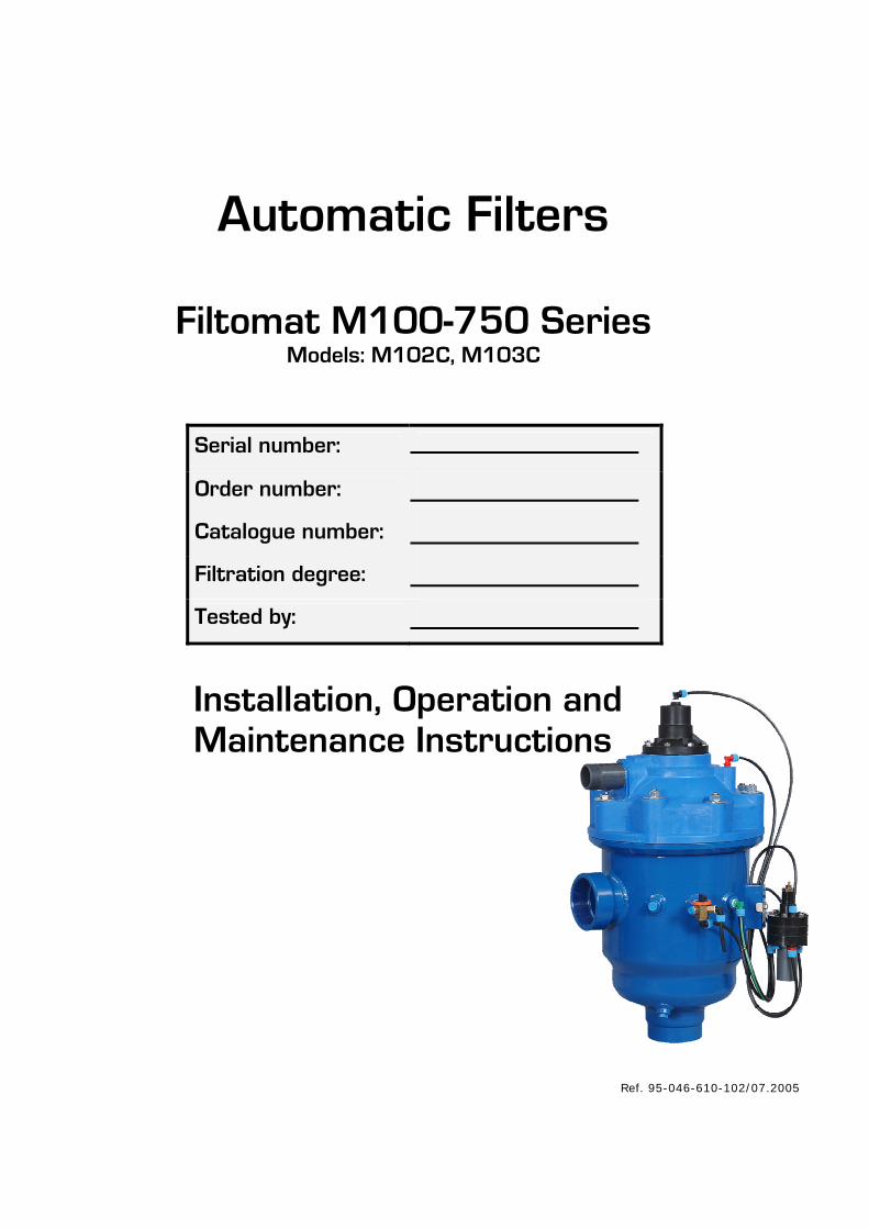
Automatic Filters
Filtomat M100-750 Series Models: M102C, M103C
Serial number:
Order number:
Catalogue number:
Filtration degree:
Tested by:
Installation, Operation and Maintenance Instructions
Ref. 95-046-610-102/07.2005

FILTOMAT M100-750 Installation & maintenance – 06.2005 - 2 -
TABLE OF CONTENTS
Specifications..............................................................................................3
Safety instructions.......................................................................................4
Dimensional drawing and recommended installation .........................................5
Introduction................................................................................................6
Installation .................................................................................................8
Preparations for installation...........................................................................9
Troubleshooting......................................................................................... 10
Adjusting the rinse controller....................................................................... 10
Maintenance ............................................................................................. 11
Parts schedule........................................................................................... 12
Parts drawing #1....................................................................................... 13
Parts drawing #2....................................................................................... 14
Parts drawing #3....................................................................................... 15
Control system.......................................................................................... 16
With any inquiry please quote the Filter Serial Number, located on the filter housing.

FILTOMAT M100-750 Installation & maintenance – 06.2005 - 3 -
SPECIFICATIONS
General
Maximum flow rate 40m3/h; 176USgpm Consult manufacturer for optimum flow depending on filtration degree & water quality.
Min. working pressure 2.0bar; 30psi Or lower if pressure is increased for flushing
Max. working pressure 8bar; 115psi
Flat screen 540cm2; 84in2 Filter area
Molded screen 700cm2; 109in2
Inlet/Outlet diameter 50, 80mm; 2", 3" Thread or flange standards as per request.
Max. working temperature 550C; 1300F
Empty / Full weight – M102C 22kg / 38kg; 49lb / 84lb
Empty / Full weight – M103C 25kg / 40kg; 55lb / 88lb
Flush data
Exhaust valve 40 mm; 11/2"
Flushing cycle time 10 seconds Depending on the working pressure
Wasted water per cycle 15liter; 4USgallon at 2bar; 30psi
Minimum flow for flushing 15m3/h; 66USgpm at 2bar; 30psi
Flush criteria Differential pressure of 0.5 bar; 7psi and manual operation
Construction materials
Filter housing Epoxy-coated carbon steel 37-2 (St. St. 316 available on request)
Filter lid High density polypropylene
Coarse screen Reinforced nylon
Fine screen Stainless Steel 316, molded plastic support structure
Cleaning mechanism PVC and Stainless Steel 316L
Motor assembly Reinforced nylon, brass, stainless steel
Control tubing Polyethylene
Seals BUNA-N
Control Aluminum, Brass, Stainless Steel 316, PVC, Acetal
Filtration degrees available Type Molded screen Flat screen
micron 500 300 200 130 100 80 800 400 200 150 130 100 80 50
mm 0.5 0.3 0.2 0.13 0.1 0.08 0.8 0.4 0.2 0.15 0.13 0.1 0.08 0.05

FILTOMAT M100-750 Installation & maintenance – 06.2005 - 4 -
SAFETY INSTRUCTIONS
General
Carefully read the installation and operation instructions prior to installation or handling of the filter.
While working with the filter all conventional safety instructions should be observed in order to avoid danger to the workers, the public or to property in the vicinity.
Note that the filter enters into a self-cleaning cycle automatically, without prior warning.
No changes or modifications to the equipment are permitted without written consent provided by the manufacturer or by its representative, on the manufacturer’s behalf.
Operation, Control and Maintenance
Loosening or unscrewing bolts should be done only after the pressure in the filter has been released.
Avoid splashing and water leakage in order to reduce danger of slipping, electrocution or damage to the equipment caused by moisture.
Always open and close valves gradually.
Remove grease and fat material residues in order to avoid slipping.
Manual cleaning of filter element using high water pressure or steam should be performed in accordance with the cleaning system instructions and without endangering the operator or his working area.
Manual cleaning of filter element using acid or other chemical agents should be performed in accordance with the relevant material safety instructions and without endangering the operator or his working area.
Use of Lifting Equipment
While using lifting equipment, make sure that the filter or the lifted part is chained securely and in a safe manner.
Avoid working below lifted equipment.
Wear a safety helmet while using lifting equipment.

FILTOMAT M100-750 Installation & maintenance – 06.2005 - 5 -
DIMENSIONAL DRAWING & RECOMMENDED INSTALLATION This is a conceptual installation drawing. Note that piping is not included.
*
753 (29.6")
400 (15.7")
554 (
21.8
")
(710)
(28")
960
(15.7
")
328 (12.9")
210 (8.3")
DRAIN
185 (7.3")
3
2
4
51 6
Key: 1. 2" Inlet manifold 2. 2" Inlet butterfly valve 3. 2" Filtomat M102-C filter 4. 2" Outlet butterfly valve 5. 2" Bypass butterfly valve 6. 2" Outlet manifold
* Minimum length required for opening.

FILTOMAT M100-750 Installation & maintenance – 06.2005 - 6 -
INTRODUCTION The FILTOMAT M100-750 is a sophisticated, yet easy-to-operate automatic filter, with a self-cleaning mechanism driven by a hydraulic turbine. The FILTOMAT M100-750 is designed to work with various types of screens with filtration degrees from 800 to 50 micron, and is available in 2" and 3" inlet/outlet diameter.
The FILTOMAT M100-750 filters are configured to meet your specific needs according to flow rates and water quality. These filters can be installed as stand-alone units for low flow rates, or assembled in a group on a manifold when high flow rates and/or a large screen area are required. The filters are delivered fully assembled, requiring a simple connection to the inlet and outlet and to the exhaust.
General Description
Water enters the filter through the inlet pipe and passes through a coarse screen which is designed to protect the cleaning mechanism from large dirt particles. It should not accumulate large quantities of suspended solids and is not cleaned automatically. The water then flows through a fine screen that filters out the smaller particles. Clean water then flows from the filter through the outlet. The particles form a "filtration cake" which accumulates on the fine screen surface. The cake build-up increases the pressure differential across the fine screen, and at a pre-set value of 0.5bar (7psi) the automatic self-cleaning cycle begins. Suction nozzles sweep across the surface of the fine screen pulling debris off and expelling it out of the exhaust valve.
This innovative self-cleaning process, utilizes the backflush technique to effectively remove the dirt particles from the fine screen, and provide an uninterrupted downstream flow during the self-cleaning cycle.
The M100-750 series filters are hydraulically operated units. No external power source is required. This type of control enables operation at remote installation sites. Alternatively, where electricity is available, an electronic controller can also be incorporated onto the filter.

FILTOMAT M100-750 Installation & maintenance – 06.2005 - 7 -
Self-Cleaning Cycle
The automatic self-cleaning cycle described below takes several seconds and does not interrupt the supply of process water.
Water flows from the inlet through the coarse and fine screens to the outlet. At a pre-set pressure differential (0.5 bar; 7 psi), the rinse controller opens the exhaust valve. The pressure in the rotor chamber drops, releasing a strong backflush stream that flows through the nozzles and then out the exhaust.
The drop in pressure and corresponding release of the backflush stream create a suction at the nozzle tips. This effect actuates spot cleaning directly in front of the openings of each nozzle on the inner surface of the fine screen.
Backflush water flows through the collector pipe, via the rotor to the exhaust valve forcing the dirt collector assembly to spin. The first backflush stroke begins when the pressure-drop in the rotor chamber permits the suction scanner assembly to move upward.
When the first stroke is completed, the exhaust valve closes and after a very short interval the rinse controller activates the second backflush stroke (downward). The dirt collector assembly moves downward returning to its original position.
The two stroke helical movement of the dirt collector assembly as described ensures that the nozzles sweep the entire inner surface of the fine screen.
This self-cleaning process takes approx. 10 seconds, depending on the operating pressure.
Exhaust valve
Rotor chamber
Rinse controller
Drain
Rotor
Fine screen
Outlet
Nozzles
Inlet
Dirt collector
Collector pipe

FILTOMAT M100-750 Installation & maintenance – 06.2005 - 8 -
INSTALLATION Read these instructions carefully before installing and operating the filter. Design Recommendations
If a prolonged pipeline fill time causes a temporary high flow and low pressure condition, it is recommended that you install a pressure sustaining valve downstream of the filter. The pressure-sustaining valve will ensure a controlled fill-up of the line.
The upstream pressure source should not drop below 2bar (30psi) during the rinse cycle. If this cannot be ensured, consult the manufacturer.
If continued water delivery is essential even during "down time" maintenance periods, it is recommended that a manual or automatic by-pass be installed, and that isolating valves be installed up and downstream of each filter unit for isolation purposes.
Avoid placing the drainage pipe on a rising slope to minimize backpressure.
Secure the open end of the drain pipe to prevent movement during the rinse cycle.
It is recommended to install a mechanical non-return valve downstream of the filter.
It is recommended to install a pressure gauge on the three-way valve.
Check that there is sufficient space to remove the cover assembly and the screen from the filter for troubleshooting.
Preparations for Installation
Ensure suitable lighting at the area of the filter to enable good visibility and safe maintenance.
Arrange suitable platforms and safety barriers to enable easy, safe access to the filter.
It is recommended to install a mechanical non-return valve downstream of the filter to prevent backflow damage to the screen.
Allow a convenient approach and enough space for dismantling and maintenance.
Installation Procedure Ensure the direction of flow according to the arrows marked on the filter housing. 1. Connect a minimum of 2" (50mm) pipe to the exhaust valve. The exhaust pipe should be
designed so that it creates minimal resistance to flow of 20m3/h (88USgpm). Water should be allowed to flow to atmosphere freely from the exhaust pipe.
2. Connect a minimum of 1" (25mm) flexible tube to the rinse controller drain port. Ensure this drain line is open to atmosphere.
IMPORTANT!!
Prevent static back pressure or reverse flow through the filter. Install a manual or a hydraulic valve downstream of the filter.
NOTE: The filter may enter flush mode automatically, without prior warning.

FILTOMAT M100-750 Installation & maintenance – 06.2005 - 9 -
PREPARATIONS Before using the filter for the first time, go through the following check-list carefully. No special training is required to carry out these activities.
Check that the upstream pressure at the filter inlet is more than 2bar (30psi) during the rinse cycle.
Check that the filter is mounted in the correct flow direction.
Check that all the control tubes are connected properly and that all connections are tight.
Check that the three-way mini-valve is turned to the automatic position. The arrow on the knob should point to AUTO, and the sticker on the filter.
The nominal diameter of the drainpipe should be 2" (50mm), in order not to restrict the drain line.
Shut the upstream and downstream isolation valves.
Check that there is sufficient space to remove the cover assembly and the screen from the filter for troubleshooting.
GETTING STARTED First operation of filter
After completing the preparation check-list above, perform the following steps:
1. Slowly open the isolating valve at the filter inlet. Water will flow into the filter.
2. Check for leaks and repair if necessary.
3. Check that the minimum inlet pressure remains 2bar (30psi) or higher.
4. Slowly open the isolating valve at the outlet of the filter.
5. If there is a by-pass valve, close it slowly.
6. Ensure the flow through the filter does not exceed the filters published maximum flow rate.
7. Start a manual flush by turning the three-way valve to the OPEN position for a few seconds, and then turn it back to AUTO.
8. During the self-cleaning cycle, check the pressure at the filter inlet and in the rotor chamber.
NOTE: The minimum pressure in the rotor chamber should be 1.5bar (22psi) lower than the inlet pressure.

FILTOMAT M100-750 Installation & maintenance – 06.2005 - 10 -
TROUBLESHOOTING Problem Possible Cause Solution
Valves are closed Open valves Pressure differential is not correct
Perform a manual flush as follows: 1. Close the filter outlet valve 2. Check that the filter outlet and inlet
pressures are equal 3. Perform a manual flush as in item 7,
page 9. 4. Check the pressures at the inlet valve
and in the rotor chamber Rinse controller dripper blocked
Change dripper
The filter does not flush
Rinse controller has been adjusted incorrectly
Check and readjust screw on rinse controller (see below)
Excessive pressure in the rotor chamber
Drain pipes are not clear Check if drain lines are clear. If necessary replace with a larger (diameter) flush drain line, or shorten the existing lines.
Insufficient inlet pressure (less than 2 bar—30 psi)
Inlet valves not fully open Open inlet valves to maximum. Increase the inlet pressure or throttle the outlet to increase pressure during the self-cleaning cycle.
Coarse filter is blocked Check coarse filter Pressure differential exceeds 0.7 bar (10 psi) during normal operation
Rinse controller needs adjusting
Adjust rinse controller (see below) Check for blockage at high pressure sensor connection.
Inlet lines blocked Check inlet lines Water does not flow through the filter Isolating valves are closed Open isolating valves
ADJUSTING THE RINSE CONTROLLER NOTE: Improper adjusting of the rinse controller may cause the filter to malfunction.
1. Disconnect the rinse controller drain line.
2. Loosen the locking nut on the long nose (1) and loosen (CCW) the adjusting screw (2) until a self-cleaning cycle begins.
3. Turn the adjusting screw (2) (CW) 1.5 times, and then tighten the locking nut (1). This adjusts the rinse controller for a differential pressure of 5m (7psi).
4. Observe at least one automatic self-cleaning cycle, if possible.
The rinse controller is adjusted for a differential pressure of 0.5bar (7psi).

FILTOMAT M100-750 Installation & maintenance – 06.2005 - 11 -
MAINTENANCE NOTE: Depressurize the filter before maintenance (close inlet, and then outlet valve).
Checking the Filter
1. Remove the filter cover by unscrewing the fastening nuts.
2. Extract the fine screen and clean if necessary. Cleaning may be performed by hosing the screen from outside-in, and/or with a nylon brush.
3. Check the coarse screen and clean if necessary.
4. Check the O-rings of the fine screen and apply grease, if necessary.
5. Reassemble the fine screen.
NOTE: Check that the dirt collector shaft is properly aligned in the bearing.
6. Return the cover and fasten the nuts.
7. Perform First Operation of Filter as on page 9.
Winterization Filter operations should be suspended in climates where the filter is exposed to freezing temperatures.
1. Check that the outlet isolating valve is closed and perform two manual rinses.
2. Close the inlet valve to the filter and release the pressure.
3. Remove all drain lines from the valves and rinse controller. These should be drained of water and re-connected.
4. Remove the following items from the filter and store in a dry place:
Top cover assembly
Coarse and fine screen assembly
Rinse controller
5. Apply grease to the O-rings of the fine screen before storing.
At the beginning of the operation season, reassemble the filter elements and check Preparations (on page 9) and First Operation of Filter (page 9).

FILTOMAT M100-750 Installation & maintenance – 06.2005 - 12 -
PARTS SCHEDULE No. Description Cat. No.
1 Filter housing 05-1XX4-12XX
1.1 Stud bolt 1/2" X 108 (X4) 85-2431-08-108
1.2 Stud bolt 1/2" X 100 (X3) 85-2431-08-100
1.3 Stud bolt 1/2" X 97 85-2431-08-097
1.4 Plastic plug 1/4" 8211-0121-0400
1.5 Plastic plug 1/4" 8211-0121-0400
2 Fine screen – flat 15-1203-0XXX
Fine screen – molded 15-1203-1XXX
2.1 O-Ring 647 81-41-4001-0674
3 Dirt collector Ass. (M100-700) 15-1024-0019
3.1 Rotor assembly 55-1006-0010
3.1.1 Lower bearing 65-3004-0602
3.1.2 Rotor bearing housing 65-1024-0026
3.1.3 Rotor 51-5510-0023
3.1.4 Self tapping screw 5/8" (X4) 85-4125-08-015
3.2 Dirt collector sub Ass. (M100-700) 15-1034-0105
3.2.1 Dirt collector top plug 65-1024-0064
3.2.2 Bolt 3/8" X 8 (X4) 85-4125-08-009
3.2.3 Dirt collector pipe (M100-700) 65-1024-0063
3.2.4 Nozzle assembly (M100-700) 55-1024-0357
3.2.6 Dirt collector bottom plug 65-1004-0060
3.2.7 Dirt collector shaft (M100-700) 65-1024-0020
4 Filter lid assembly 15-1070-024
4.1 Filter lid 55-1070-0090
4.2 O-Ring 6/3 81-41-4100-0603
4.3 Plug 1/4" BSP 82-11-0121-0400
4.4 Nut 1/4" 85-2231-04-000
4.5 Washer 65-1008-0212
4.6 O-Ring (P2-107) 81-41-4000-0107
4.7 L-Connector 6 X 1/4" 82-11-6469-4604
No. Description Cat. No.
4.8 Diaphragm 81-41-4561-0003
4.9 Spring support 61-5510-0042
4.10 Spring 65-1008-0202
4.11 Spring plug guide 61-5510-0041
4.12 Rod tie 65-1008-0203
4.13 Washer 1/4" (X8) 85-2312-06-000
4.14 Nut 1/4" (X8) 85-2211-04-000
4.15 Diaphragm cover 51-5510-0021
4.16 L-Connector 6 X 1/4" 82-11-7469-4604
4.17 Rod tie (X7) 65-1024-0102
4.18 Rod-tie diaphragm support 65-1024-0031
4.19 O-Ring (P2-107) 81-41-4000-0107
4.20 Nut 65-1008-0007
4.21 Exhaust valve assembly 55-1006-0100
4.21.1 Exhaust valve seal 81-41-4561-0047
4.22 Exhaust valve seat 55-1006-0206
4.23 O-Ring 81-41-4000-0351
5 Flushing chamber 51-5510-0025
6 Self tapping screw 5/8" X 8 85-4125-08-015
7 Lid seal 81-41-4561-3015
8 Jam nut 1/2" 85-2221-08-000
9 Nut 1/2" (X7) 85-1211-08-000
10 Washer 1/2" (X8) 85-1311-08-001
11 Nipple 11/2" NPT 83-2920-0151-0105
Nipple 11/2" BSP 83-2920-0150-0105
12 Rinse controller 15-1007-0101
12.1 Bolt 1/4" 85-41-1104-012
13 3-Way valve 84-3170-0011
13.1 Nipple 1/4" X 1/8" 83-4324-1012-1925

FILTOMAT M100-750 Installation & maintenance – 06.2005 - 13 -
PARTS DRAWING #1

FILTOMAT M100-750 Installation & maintenance – 06.2005 - 14 -
PARTS DRAWING #2

FILTOMAT M100-750 Installation & maintenance – 06.2005 - 15 -
PARTS DRAWING #3

FILTOMAT M100-750 Installation & maintenance – 06.2005 - 16 -
CONTROL SYSTEM
DRAIN
B
C
A
D
ADC B