m1 manual instalacao en v2 - flymasterdownloads.flymaster.net/m1 user manual_en.pdf · this manual...
TRANSCRIPT

M1M1M1M1
User manual
Version 1.0

M1�Installation�Manual
2010�FLYMASTER�Avionics�Ltd.
R. Comendador Rainho, 192 - Apartado 1183701-910 S. João da MadeiraPortugalTel: + 351 256 880 568Fax: + 351 256 880 551
All rights reserved. Except as expressly provided herein, no part of thismanual may be reproduced, copied, transmitted, disseminated, downloaded orstored in any storage medium, for any purpose without the express priorwritten consent of FLYMASTER Avionics Lda. herein FLYMASTER avionics.FLYMASTER Avionics hereby grants permission to download a copy of thismanual onto a hard drive or other electronic storage medium to be viewed andto print a copy of this manual or of any revision hereto, provided that suchelectronic or printed copy of this manual must contain the complete text of thiscopyright notice and provided further that any unauthorized commercialdistribution of this manual or any revision hereto is strictly prohibited.
Information in this document is subject to change without notice.FLYMASTER Avionics reserves the right to change or improve its products andto make changes in the content without obligation to notify any person ororganization of such changes or improvements. Visit the FLYMASTER Avionicswebsite (www.flymaster-avionics.com) for current updates and supplementalinformation concerning the use and operation of this and other FLYMASTERAvionics products.
Version 1.0

Warning
It is the sole responsibility of the pilot to operate the aircraft in a safe manner,maintain full surveillance of all flying conditions at all times, and not becomedistracted by the Flymaster�M1. Flymaster Avionics is not responsible forany damages resulting from incorrect or no data provided by the Flymaster
M1. Flight safety is the sole responsibility of the pilot.
It is unsafe to operate the Flymaster�M1 while in the air. Failure by thepilot equipped with a Flymaster�M1 to pay full attention to the aircraft andflying conditions while flying could result in accident with property damageand/or personal injury.
3 Version 1.0

M1�Installation�Manual
Table of contents
Table of contents
1. Introduction.................................................................................................................5
2.Getting Started..............................................................................................................5
2.1.M1 Keys...............................................................................................................................6
2.2.Switching M1 On and Off...................................................................................................6
3.Flight Data.....................................................................................................................7
4.Settings Menu................................................................................................................9
4.1.Date and Time...................................................................................................................10
4.2.Reset Counter....................................................................................................................10
4.3.Temperature Offset...........................................................................................................10
4.4.Stroke Number...................................................................................................................10
4.5.Fuel Settings......................................................................................................................11
4.5.1.Tank Calibration......................................................................................................................11
4.5.2.Sensor Calibration...................................................................................................................11
4.5.3.Tank Empty.............................................................................................................................11
4.5.4.Fuel Units.................................................................................................................................12
4.5.5.Average Fuel Consumption.....................................................................................................12
5.Fuel Sensor Installation Procedure...........................................................................12
5.1.Fuel Sensor Position.........................................................................................................13
5.2.Fuel Sensor .Cutting Procedure........................................................................................14
5.2.1.Deciding Sensor Length .........................................................................................................14
5.2.2.Cutting the Metallic Tube........................................................................................................16
5.3.Sensor Calibration Procedure..........................................................................................18
5.4.Tank calibration................................................................................................................20
6.Temperature Sensor Installation..............................................................................22
7.RPM Sensor Installation............................................................................................23
8.Updating firmware.....................................................................................................24
Version 1.0 4
1. Introduction
Thank you for choosing FLYMASTER�M1. If you have any questions orcomments regarding the use of our instruments you can visit our website orcontact our Support Department ([email protected]).
This manual covers Firmware versions up to 1.2. If have a more recentversion of firmware some of the features may not be covered.
2. Getting Started
Fully charge battery before using FLYMASTER�M1 for the first time.
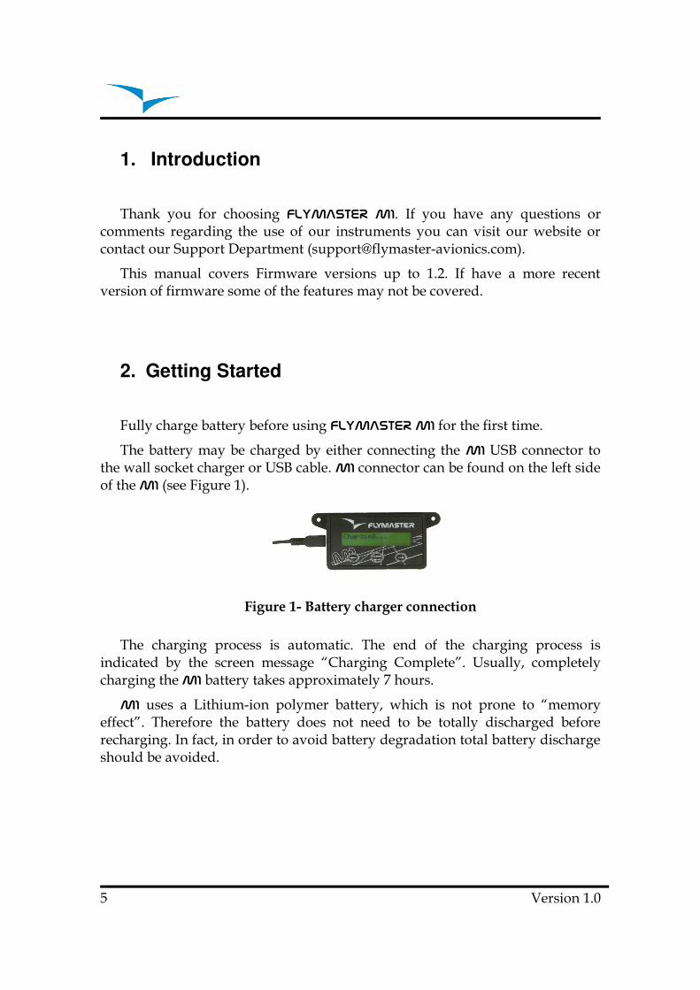
The battery may be charged by either connecting the M1 USB connector tothe wall socket charger or USB cable. M1 connector can be found on the left sideof the M1 (see Figure 1).
Figure 1- Battery charger connection
The charging process is automatic. The end of the charging process isindicated by the screen message “Charging Complete”. Usually, completelycharging the M1 battery takes approximately 7 hours.
M1 uses a Lithium-ion polymer battery, which is not prone to “memoryeffect”. Therefore the battery does not need to be totally discharged beforerecharging. In fact, in order to avoid battery degradation total battery dischargeshould be avoided.
5 Version 1.0

M1�Installation�Manual
2.1. M1�M1�M1�M1�Keys
Figure 2 - FLYMASTER�M1�Keyboard
Three keys are used to interact with M1 (see Figure 2). Depending thecontext each key can have more than one function. Key functions are indicatedby a symbol, or word. The available functions are indicated in Table 1.
Table 1 – Key Functions
KeyFunction
Flight Mode Menu Mode
S1
(←←←←) • Change Line 1 Data;
• Change Menu Option (leftoption);
• Decrements parametervalues.
S2(Menu)
• Turn On;
• Change to Menu Mode, • Confirm Actions
S3
(→→→→) • Change Line 2 Data;
• Change Menu Option(Right option);
• Increments parametervalues.
2.2. Switching M1�M1�M1�M1� On and Off
To switch on the M1, briefly push the S2 key. This will display the start upscreen showing the M1 �serial number, firmware version and a 10 secondcountdown. Pushing S2 before the end of the countdown will initiate the M1.
To switch off the M1 , activate menu mode by pushing the S2 (menu) key.Using keys S3, or S4, chose “Shutdown” menu option. Finally, push the S2(Enter) Key to confirm.
Version 1.0 6
The M1 �includes a large flight memory. Whenever, motor rotation isdetected for more than 3 consecutive seconds, flight recording is started.
Flight recording is terminated whenever motor rotation stops. Flight logscan be downloaded to the PC using the USB port and adequate software.
3. Flight Data
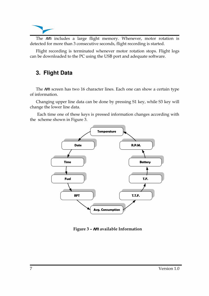
The M1�screen has two 16 character lines. Each one can show a certain typeof information.
Changing upper line data can be done by pressing S1 key, while S3 key willchange the lower line data.
Each time one of these keys is pressed information changes according withthe scheme shown in Figure 3.
Date
Time
Temperature
R.P.M.
Battery
RFT
Avg. Consumption
Fuel
T.T.F.
T.F.
Figure 3 – M1M1M1M1 available Information
7 Version 1.0
M1�Installation�Manual
The meaning of each data field is the following:
Temperature – External probe temperature in ºC. (maximum temperature is250ºC)
Date – Date in the format Year:Month:Day. Data can be adjusted usingmenu (see section Date and Time).
Time – Time in the format Hour:Minute:Second. Time can be adjusted usingmenu (see section Date and Time).
Fuel (level) – Indicates the tank fuel level. The fuel level can be in centilitres,or percentage, according with the “fuel units” settings (see section 4.5.4). Thefuel level is calculated by measuring the fuel column, therefore its' accuracydepends on tank calibration and inclination. To correctly calibrate the tank referto the “Tank Calibration“ section.
Remaining Fuel/Flight Time (RFT) – Gives the remaining fuel time in theformat Hour:Minute. This time is calculated considering the tank level andaverage fuel consumption.
Average Consumption (Avg. Con.) – Indicates the average consumptionsince last user change. The average consumption is updated periodically oncerpm is greater than zero. The Average Consumption value can be changed bythe user in the “Fuel Settings” menu (see section 4.5.5 Average FuelConsumption).
Total Flight Time (T.F.T.) – Shows the total flight time since last timer reset.Timer reset can be done trough “T.F.T.” menu option (see section 4.2. ResetCounter).
Flight Time (F.T.) – Indicates current flight time. The timer is started oncerpm is detected.
Battery – Indicates the remaining battery level in percentage. M1 uses aLithium-ion polymer battery, which is not prone to “memory effect”, Thereforethe battery does not need to be totally discharged before recharging. In fact, inorder to avoid battery degradation total battery discharge should be avoided.
RPM – Motor angular speed in Revolutions Per Minute. The motor RPM isdetermined using an electromagnetic sensor which detects the supply sparkplug current. Depending on the motor type, in order to have the correct value ofRPM the number of spark plug ignitions detected must be multiplied by acertain factor. This multiplication factor may be adjusted by the user on theconfiguration menu (see section 4.4 Stroke Number).
Version 1.0 8
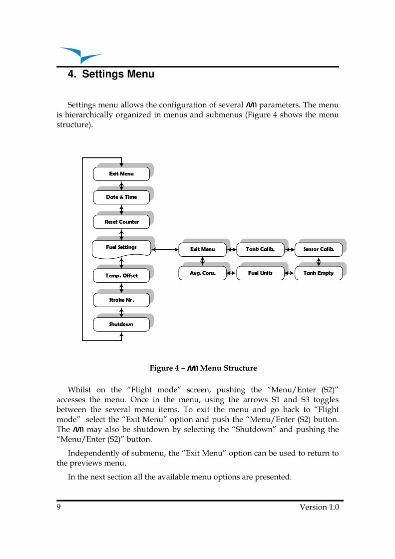
4. Settings Menu
Settings menu allows the configuration of several M1 parameters. The menuis hierarchically organized in menus and submenus (Figure 4 shows the menustructure).
Fuel Settings
Exit Menu
Date & Time
Reset Counter
Temp. Offset
Stroke Nr.
Shutdown
Exit Menu Tank Calib. Sensor Calib.
Tank EmptyFuel UnitsAvg. Cons.
Figure 4 – M1M1M1M1 Menu Structure
Whilst on the “Flight mode” screen, pushing the “Menu/Enter (S2)”accesses the menu. Once in the menu, using the arrows S1 and S3 togglesbetween the several menu items. To exit the menu and go back to “Flightmode” select the “Exit Menu” option and push the “Menu/Enter (S2) button.The M1 may also be shutdown by selecting the “Shutdown” and pushing the“Menu/Enter (S2)” button.
Independently of submenu, the “Exit Menu” option can be used to return tothe previews menu.
In the next section all the available menu options are presented.
9 Version 1.0
M1�Installation�Manual
4.1. Date and Time
The M1 has a internal clock, and calendar, which are responsible for timeparameters. The “Date and Time” menu option allows the user to set the clockand calendar.
After “Date and Time” menu option selected the date will appears on thescreen. Values can be set using S1 and S3 key. Confirming one value will allowchanging the next one.
4.2. Reset Counter
The M1 includes two flight time counters. One indicates the current flighttime, and the other indicates the total flight time since the last reset. Both timersare automatically started when RPM is detected, and stopped when RPM iszero. However, whilst the flight time counter is initiated whenever the flightstarts, the total flight time counter accumulates the total of all flights.
The “Reset Counter” menu option allows the user to reset the total flight timecounter.
The total flight time counter is useful to control the number of motor workinghours in order to schedule preventive maintenance tasks.
4.3. Temperature Offset
This option allows the user the calibration of the external temperaturesensor. This is accomplished by setting a certain offset.
4.4. Stroke Number
The motor rotation is determinate using an electromagnetic sensor whichdetects the supply spark plug current.
Depending on the motor type, in order to have the correct value of R.P.M.the number of spark plug ignitions detected must be multiplied by a certainfactor. This multiplying factor can be changed by the user trough this option.
The current version of firmware allows two motor types, specifically 2 and 4stroke motors. The multiplying factor for the 2 stroke motors is 1. This meansthat the number of ignitions is equal to the number of rotations. Alternatively,the multiplying factor for 4 stroke motors is 2. This means that the number ofignitions is half of the number of rotations.
Version 1.0 10

4.5. Fuel Settings
The “Fuel Settings” submenu allows the adjustment of several parameters,and procedures related with the fuel level measurement and sensor. Theavailable options in this submenu are described in the following sections.
4.5.1. Tank Calibration
The available fuel on tank is calculated from the measure of the fuel heighton tank. Depending on tank configuration, the same fuel height can givedifferent fuel quantity. In order to get a more accurate value , is need tocalibrate the thank. This calibration procedure establishes a relation betweenfuel height and fuel quantity.
The calibration procedure is explained in section 5.3 Sensor CalibrationProcedure.
4.5.2. Sensor Calibration
The fuel sensor supplied with M1 is factory calibrated. However, the sensorlength can be cut to size . Cutting the fuel sensor length involves several tasksbeing the last one the Sensor Calibration.
This menu option allows fuel sensor calibration after being cut. Thecalibration procedure is necessary in order the M1 recognize the new length.The procedure is explained in section 5.3 Sensor Calibration Procedure
4.5.3. Tank Empty
The tank calibration procedure is made in certain conditions which can bedifferent from that on flight day. This option allows the definition of a newempty set point.
In order to define the new empty point the following procedure should bedone:
1. Completely empty the fuel tank;
2. Choose “Tank Empty” option and follow the instructions onscreen.
11 Version 1.0

M1�Installation�Manual
4.5.4. Fuel Units
Fuel level can be shown in Percentage or Centilitres. This option allowsdefining which unit should be used. If percentage is chosen the calculation isbased on the maximum fuel level defined during tank calibration procedure.
4.5.5. Average Fuel Consumption
The average consumption is calculated during flight, dividing periodicallythe value of consumed fuel by the elapsed time. This calculation is repeatedindefinitely when the rotation is greater than 0 and the fuel level can bedeterminate. The Average Fuel Consumption is shown in Litres per Hour(L/H).
This menu option allows the user to change the Average Fuel Consumptionvalue. Since values need to be calculated using averages, these need some timeto be obtained, therefore the user can manually insert a reference value so thatother calculations that depend on this value can be immediately carried out.
5. Fuel Sensor Installation Procedure
Caution: The fuel sensor installation is a delicate, and potentially dangerous,process, which should only be carried out by skilled technicians. The sensor isfuel certified, but the incorrect installation, or use, may have seriousconsequences.
Figure 5 – Fuel Sensor Installation Example
Version 1.0 12

5.1. Fuel Sensor Position
Considering the height measured by the sensor is proportional to the lengthof the immersed part, the fuel sensor should be vertically installed (see Figure 6a)). However, an inclined position is possible provided that sealing isguaranteed (see Figure 6 b)).
Figure 6 – Installation position
In order to grant the measure accuracy the sensor tube should not have anyobstacle closer than 10 mm (see Figure a)). Special care should be taken withthe distance to the tank bottom.
If required the sensor length can be reduced trough the procedure defined insection 5.2 Fuel Sensor .Cutting Procedure.Otherwise, the installationcontinues with tank calibration according section 5.4 Tank calibration.
13 Version 1.0
M1�Installation�Manual
5.2. Fuel Sensor .Cutting Procedure
The fuel sensor supplied with M1 has a default length. If required the sensorcan be shortened.
The first step for shortening the fuel sensor is to decide the correct length ofthe metallic tube which will be inserted in the tank.
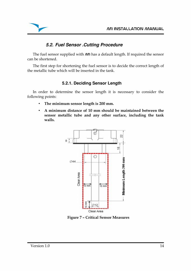
5.2.1. Deciding Sensor Length
In order to determine the sensor length it is necessary to consider thefollowing points:
• The minimum sensor length is 200 mm.
• A minimum distance of 10 mm should be maintained between thesensor metallic tube and any other surface, including the tankwalls.
Figure 7 – Critical Sensor Measures
Version 1.0 14
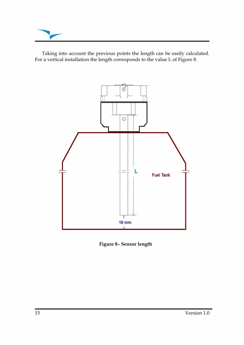
Taking into account the previous points the length can be easily calculated.For a vertical installation the length corresponds to the value L of Figure 8.
Figure 8– Sensor length
15 Version 1.0

M1�Installation�Manual
5.2.2. Cutting the Metallic Tube
The sensor cut should be made using an adequate tool (eg. Pipe Cutter; finetoothed hacksaw).
Figure 9 – Cutting the Sensor
After cutting the metallic, outer, and inner tube carefully remove theremaining jagged edges using adequate tool.
Figure 10 – Sensor after being cut
Version 1.0 16

The sensor has a small hole on the bottom. This hole is necessary to allowfuel entry. (see Figure 11).
Figure 11 – Sensor hole
If cutting the sensor leads to the elimination of the hole a new one should bemade using 4 mm drill.
After all the above procedures were done all the surfaces must be cleanedand specially without filings.
The cutting procedure is terminated with the insertion of the special PTFEterminator supplied with the sensor (see Figure 12).
The main objective of this terminator is to avoid the contact between thecentre aluminium rod and the outer tube. Furthermore, the distance betweenthe rod and the outer tube should be keep constant along all sensor length.
Attention: Contact between the centre aluminium rod and the outer tubealters significantly the measures.
Figure 12– End Plug placement
17 Version 1.0
M1�Installation�Manual
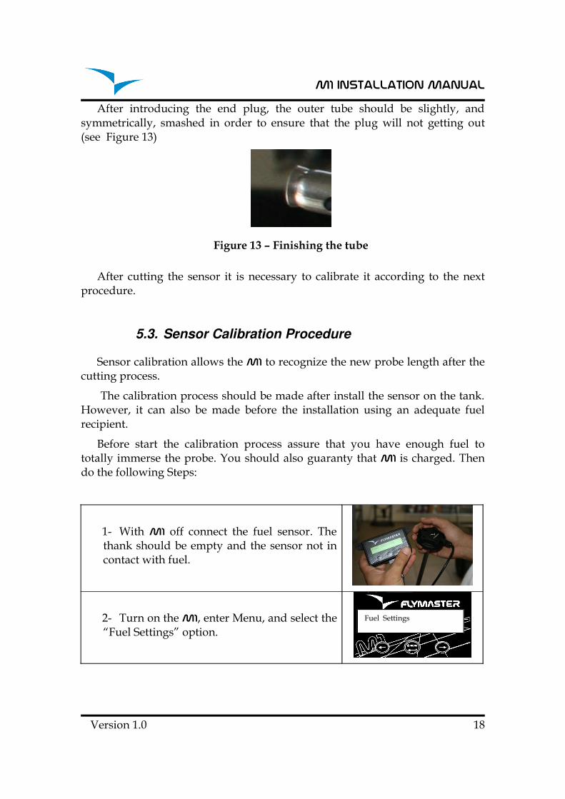
After introducing the end plug, the outer tube should be slightly, andsymmetrically, smashed in order to ensure that the plug will not getting out(see Figure 13)
Figure 13 – Finishing the tube
After cutting the sensor it is necessary to calibrate it according to the nextprocedure.
5.3. Sensor Calibration Procedure
Sensor calibration allows the M1 to recognize the new probe length after thecutting process.
The calibration process should be made after install the sensor on the tank.However, it can also be made before the installation using an adequate fuelrecipient.
Before start the calibration process assure that you have enough fuel tototally immerse the probe. You should also guaranty that M1 is charged. Thendo the following Steps:
1- With M1 off connect the fuel sensor. Thethank should be empty and the sensor not incontact with fuel.
2- Turn on the M1, enter Menu, and select the“Fuel Settings” option.
Version 1.0 18
Fuel Settings

3- Choose the “Calibrate Sensor” option
4- The M1 ask you to confirm the sensorcalibration process. By default the flashingoption is “No”, so you should choose “Yes”.
5- The sensor ask you to confirm that sensoris dry (i.e. not in contact with the fuel). Youshould choose “Yes”.
6- A message “Wait…” appears on thedisplay while the M1 acquire the empty tankstate. The acquisition takes approximately 3seconds.
7- After 3 seconds have elapsed the M1 willask if the sensor is fully immersed. Fill thetank to full capacity making sure the sensor isfully immersed. appears asking if the sensor isimmersed.
8- When the tank is completely immersed thevalue on the screen should be around 1000(the value should be greater than 200). At thispoint you should confirm the value using S2key.
9- A message “Wait…” appears on thedisplay while the M1 acquire the full tankstate. The acquisition takes approximately 6seconds.
10- If the calibration was successful than themessage “Sensor Calibrated” appears on thescreen, otherwise an error message will beshown. Despite the message you should pressa key in order to continue.
19 Version 1.0
Calibrate Sensor
Are You SureYes No
Sensor Dry?Yes No
Wait ....
Sensor Immersed?Ok Value: 923
Wait ....
Sensor Calibrated

M1�Installation�Manual
5.4. Tank calibration
The available fuel is calculated from the measure of the fuel height on tank.Depending on tank configuration, the same fuel height can give different fuelquantities. In order the right calculation can be made a calibration procedure isnecessary. This calibration procedure establishes a relation between fuel height,and fuel quantity.
The calibration process is based on a simple idea. After asking for a standardmeasure definition, the M1 keeps asking the user to spill measures on the tankuntil it is full. For each added measure the corresponding height is saved. Laterthe fuel quantity can be calculated by interpolation.
The calibration process requires one M1 and a calibrated fuel sensorcorrectly installed. If enough fuel is available to completely fill the tank ,followthe next steps:
1- Start with an empty tank, and the fuel sensorcorrectly connected to the M1.
2- Turn on M1. Enter menu mode and select“Fuel Settings”.
3- Within the Fuel Settings menu select“Calibrate Tank” option.
4- The first step is the definition of the standardmeasure. By default the standard measure is 100cl. In this step user can alter the standardmeasure value, or skip the alteration andmaintain the previews definition.
5- The standard measure value can varybetween 5cl and 200cl. Value can be altered usingkeys S1 and S3 and confirmed using S2 Key.
Version 1.0 20
Calibrate Tank
Set Measure?Skip Val=150cl
Use <- and ->Value: 150cl
Fuel Settings

6- Depending on the first value measured by thesensor the M1 can ask the user to confirm if tankis really empty. In case “No” is selected thecalibration process is aborted.
7- In this step M1 waits for a fuel quantity, equalto the “standard measure” value, be added in thetank. For example, if the standard measure valueis 100 cl, then 100 cl of fuel should be added inthe tank. After putting the fuel on tank it isimportant to wait for the stabilization of the fuelbefore selecting “Done” option.
8- After a measure being added the M1 asks theuser if tank is full. If “No” is selected the processreturns to point 7, otherwise, all values are savedin memory and calibrations ends.
Note: Smaller “standard measure” values allow more accurate fuel levelcalculation, particularly in tanks with irregular shapes. However, the chosenvalue should cause fuel height variations greater than 1 centimetre. Themaximum number of measures is 30.
Once the calibration is done M1 can calculate data as: fuel level; average fuelconsumption; remaining flight time.
21 Version 1.0
Tank Empty?No Yes
Waiting MeasureDone Cancel
Tank Full?No Yes

M1�Installation�Manual
6. Temperature Sensor Installation
The temperature sensor supplied with M1 is a thermistor capable ofmeasures up to 250ºC.
Figure 14 – Example of Temperature Sensor Installation Local
The sensor terminator is a standard M8 ring which can be installed in anymotor screw. The installation in a screw instead of more common spark pluginstallation has several advantages, namely:
• It’s easier to install since most of the times the spark plug holeis to small and inaccessible.
• It’s more definitive since it is not necessary to remove thesensor when spark plug need to be changed.
• It’s more robust since working temperature range is smaller.
The main drawback of the sensor installation in a screw is an higher delay inthe response to a motor temperature increase.
Flymaster can supply different temperature sensors with different measures.
Version 1.0 22
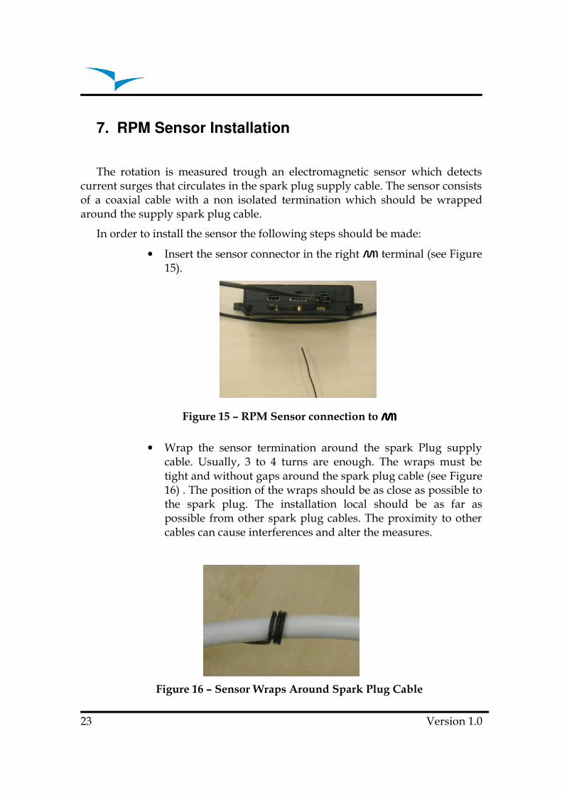
7. RPM Sensor Installation
The rotation is measured trough an electromagnetic sensor which detectscurrent surges that circulates in the spark plug supply cable. The sensor consistsof a coaxial cable with a non isolated termination which should be wrappedaround the supply spark plug cable.
In order to install the sensor the following steps should be made:
• Insert the sensor connector in the right M1 terminal (see Figure15).
Figure 15 – RPM Sensor connection to M1M1M1M1
• Wrap the sensor termination around the spark Plug supplycable. Usually, 3 to 4 turns are enough. The wraps must betight and without gaps around the spark plug cable (see Figure16) . The position of the wraps should be as close as possible tothe spark plug. The installation local should be as far aspossible from other spark plug cables. The proximity to othercables can cause interferences and alter the measures.
Figure 16 – Sensor Wraps Around Spark Plug Cable
23 Version 1.0

M1�Installation�Manual
The ideal number of turns is difficult to predict since it depends on severalfactors. A higher number of turns increase sensibility to the R.P.M., but alsoto noise, so more interferences can occur. A lower number decreasessensibility which can cause wrong measures especially at higher rotationvalues.
After install the sensor, if the rotation value is not correct different numberof turns and sensor position should be tried.
8. Updating firmware
The update of the firmware is a simple procedure that adds new features tothe M1 firmware.
Before beginning update procedure make sure you download from our site(www.flymaster-avionics.com) the next list of files:
• FlymasterUSBdrivers.msi (USB Drivers)
• M1Firmware.m1n (Firmware M1)
• FlashM1Install.msi(updating software)
When you have all the files you can start the update procedure.
The first step of the updating procedure consists in installing the USBdrivers on the PC. In order to do that you should run theFlymasterUSBdrivers.msi file and follow the on-screen instructions.
Next you need to install the update application, run the FlashM1Install.msiand follow the on-screen instructions.
1- Execute the FlashM1Install.msi application.
2- Select the M1Firmware.m1n file previously downloaded from the website.
3- Push the “Send” button. A message “Waiting M1…” will appear onscreen.
4- Hold the “Menu” (S2 key) button on your M1, and insert a paper clip intothe reset orifice on just above the usb connector on the M1 in such a wayas to reset the M1.
Version 1.0 24

5- Release the reset button while keeping the “Menu” button. Once you seea message on the FlashM1 “Erasing memory…” you may release the“Menu” button. If the message doesn’t appear within 5-7 seconds resetthe M1 again.
6- Wait until you see the message “Complete.”
25 Version 1.0