m. yankelevich - core
TRANSCRIPT

Municipal economy of cities, 2016, issue 132 ISSN 0869-1231
2 © Yankelevich M.
M. Yankelevich
The design–built company “PARSONS”, New York, USA
FROM MY EXPERIENCE IN USA.
THE FORMER TERMINAL A IN AIRPORT “LOGAN”
Information presented in this article is about former Terminal A building reinforced concrete structures
performance, load bearing capacity study of structures and the demolition project. That was one of the first
buildings in USA were the most of flexural elements were cast-in-place post-tensioned reinforced concrete. The
building Terminal A was constructed in 1968, became obsolete, did not satisfy modern technological requirements
and was demolished in 2002.
Keywords: post-tensioned reinforced concrete, load bearing capacity, monitoring, and demolition.
Airport “Logan” is sadly known all over the world
as the airport where flights initiated and resulted in
terrible events of September 11, 2001. However, for me
this airport is the place from which I was flying for
business trips and vacations, as well as a place of many
projects in which I was involved. I was involved in
study and design of several terminals, of people mover
bridges, performed construction services.
Some tasks presented in this article were
performed to support temporary service of the old
terminal building. The building was in service for 30
years, obsolete but had to be used until new building
was designed and its construction began.
Fig.1. Terminal A Former Building
Building Terminal A (Fig. 1) was designed by
Architect- MINORU YAMASAKI & ASSOCIATES,
Structural Engineer- SEPP FIRNKAS ENGINEERING
and constructed in 1968. It was one of the first buildings
in USA were main structures were post-tensioned cast-
in-place reinforced concrete.
Presented is a “detective” story where “main
hero”, Terminal A, was “killed” – demolished (Fig. 11)
at the start. However, the story is: what had happened
before this.
1В відомостях про автора в науково-технічному збірнику “КОМУНАЛЬНЕ ГОСПОДАРСТВО
МIСТ 124/2015” допущена неточність: Марк Янкелевича не було вписано до списку вчених США, у
2002/2003 роках, а було внесено в “America’s Registry of Outstanding Professionals” - книгу, що
містить відомості про професіоналів за різними напрямками.
brought to you by COREView metadata, citation and similar papers at core.ac.uk

The design, construction and maintenance of urban economy buildings and structures
3
Fig.2. Typical Garage Floor of Terminal A
Fig.3. Roof Plan of Terminal A
The building presented (Fig. 2) was supported by
columns with grid 60 x 60 feet (≈ 18 x 18 m.). As in
typical terminals, there were the Departure and Arrival
floors (2 lower floors), and also it had four parking
garage floors and roof. The roof had additional parking
areas at the total perimeter: the cantilevers on the west,
south and east sides and an additional span with a total
width canopy supported by the row of high columns on
the north side (Fig. 3, 4).
The first task assigned to Weidlinger Associates in
1997 was the Wind Vulnerability Study. We were
informed that the new project will be developed for
Terminal A. However, the existing building should be in
service about 4 years until it would be demolished and
the new building would began to be constructed. The
project of the existing building was developed in time
when the wind and live loads used in design were
smaller than should been used per Codes [1] of present
time. The assignment was to verify that the existing
building could sustain the required per current Codes
design wind and live loads for the future 4 years.
The first view on the plan of building (Fig. 2)
showed that monolithic ramps placed between two
concrete circular walls were located at the each side of
the building. These walls were interconnected at 5
levels with monolithic floor slabs and roof. Since this at
first the wind load seemed to be not a problem.
However, a further study showed that one of the outer
circular walls of rump were not supported by the
foundation but placed on columns at the first level.
Municipal economy of cities, 2016, issue 132 ISSN 0869-1231
4
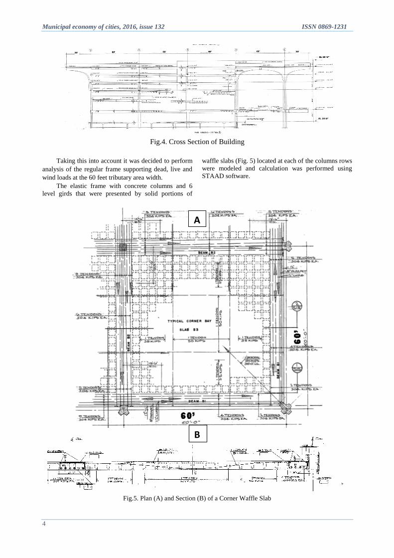
Fig.4. Cross Section of Building
Taking this into account it was decided to perform
analysis of the regular frame supporting dead, live and
wind loads at the 60 feet tributary area width.
The elastic frame with concrete columns and 6
level girds that were presented by solid portions of
waffle slabs (Fig. 5) located at each of the columns rows
were modeled and calculation was performed using
STAAD software.
Fig.5. Plan (A) and Section (B) of a Corner Waffle Slab
B
A

The design, construction and maintenance of urban economy buildings and structures
5
Checking the concrete sections under the factored
designed forces we revealed that the outer columns
connections to the girds at the first three levels had the
moments that were up to 15% larger than the capacity of
sections while the forces in the joints at middle columns
and girds sections were more than 50% smaller than the
capacity of their sections. Inspection of the structures
was performed and revealed that the edge columns had
visual cracks. No cracks were found in interior sections.
It was decided to place at the design model plastic
hinges in connection of girds to the outer columns and
applies in hinges the moments corresponding to the
minimum moment capacity of columns or girds.
Reviewing the forces in all critical sections obtained by
this analysis under all design load combinations we
found out that the load capacity of frame was in the
allowable limits. Based on this and taking into account
the 30 years of framing service we made a positive
conclusion on the results of Wind Vulnerability Study.
While performing this study one day in 1998 we
received a call from the terminal service personal that
something happened at night in one of the building
rooms. Inspection of that room showed that on the
second floor in cafeteria kitchen the floor tiles were
popping out. The visual inspection of the waffle slab
soffit at this place had not shown any damage or even
cracks in the ribs of the slab. It was concluded that this
was not a structural problem. It was assumed that the
often watering of this floor could some way expand the
mortar under the tiles that caused their popping. The
floor was repaired.
However, after the year and a half passed, the
similar accident happened at the day time. The staff
heard a sudden sharp noise and felt vibration after
which the tiles popped out at the same place. It was
realized that something happened with the waffle slab
reinforcement.
The 4” thick waffle slab reinforced with #3 (≈10
mm diameter) at 12” (≈305 mm) had ribs spaced 3x3
feet (≈914x 914 mm) of total depth 2 feet (≈610 mm)
and average width 7” (≈178mm). The ribs were
reinforced with the post-tensioned 7 wire tendons 0.6”
diameter (≈15mm) which were greased and did not have
cohesion with concrete – were un-bonded.
It was a possibility that at least one of 5 mm wires
in a tendon was broken creating a noise and vibration. It
was a mechanical room under the kitchen room. The
supporting post was promptly installed directly under
the place of tiles popping.
It was made a decision to analyze the waffle slab.
First the slab with local supporting post was checked.
The post was installed near the span diagonal, about 13
feet (≈ 4m.) from the center of interior column.
The maximum forces at slab sections based on the
elastic slab analysis were not larger than load bearing
capacity in the critical sections.
However, the most critical was the corner slab that
was not continuous on two corner exterior sides of the
building. On one of the upper floors the popped up tiles
were also found out in the closed at the most of time
storage room located at the corner slab (Fig. 6).
The elastic analysis of waffle slab was performed
using the model that included four slab units on 9
columns below and above in which interior sides were
moment restrained (continuous) and exterior sides
between the columns were free. The results of analysis
showed that the span positive moment in the critical
span section of the corner slab was about 30% larger
than the moment capacity of the critical section.
Based on such results, we performed the yield line
analysis of this slab calculating the moment capacity of
sections using fps - stress in prestressed tendons at
nominal strength [2] and project specified stresses of
concrete. The load bearing capacity of the slab based on
this analysis was equal of: Plimit = 0.365 ksf. The service
load on the airport slab included 0.138 ksf dead load
and 0.1 ksf live load – 0.238 ksf total load. The
safety factor obtained was equal of SF = 1.53,
which was 8% smaller than minimal safety factor
that would be provided by the load factor design:
SF = (1.4DL + 1.6 LL)/[φ(DL+LL)] = (0.138
x 1,4 + 0.1 x 1.6)/(0.9 x 0.238) = 1.65.
Taking into account that yield-line analysis
does not comply with the standard design practice
in the USA and even this analysis shows about 8%
overstress under the design load, it was decided to
perform additional study of slabs behavior:
The crack width gages were installed on
cracks at several slab ribs (Fig. 7) and the crack
width monthly monitoring were performed during
6 month period.
Monthly survey was performed on random
bays of floors to monitor the deflections variation
during 6 month period too.
Observations were made to figure out the
real maximum live loads on the floors.

Municipal economy of cities, 2016, issue 132 ISSN 0869-1231
6
Fig.6. Popped Tiles on Corner Slab
A research laboratory was hired to perform first
two tasks. The load observation was performed by
counting the equipment weights and visiting the
terminal areas at most critical days on the eve of
government holidays. The maximum load that was
estimated at the crowded departure floor occurred to be
not more than 30 psf (pounds per square foot) ≈ 150
kg/m2, while the design live load at airport by Code
used in calculations was 100 psf (≈500 kg/m2).
Since the cracks width and the deflections during
the half year observation had not been increased and the
observed load was much less than the design load, we
concluded that the airport building could stay in
temporary service.
However, some other problems emerged during
the observation of building structures.
The two spiral ramps for car traffic to parking
garages located at the upper floors at the west and east
edges of the building were designed different way
(probably for research goals). The east ramp slab had
non-prestressed reinforcement mesh while the west
ramp slab was reinforced with radial prestressed
tendons.
Fig.7. Monitor on the Crack on the Waffle Slab Rib
The observations of ramps showed that in several
places the both ramp slabs had deterioration of concrete
with open reinforcement covered with rust (Fig. 8). It
should be noted that these ramp slabs are actually 8” (≈
200mm.) thick one way slabs with 16 ft (≈ 5m.) span
restrained on both sides in circular 1 foot (≈ 30mm.)
thick walls and in such arrangement restricted not only
from rotation but also from horizontal movement.
The investigations of such slabs [3, 4, 5] show that
their capacity drastically increases due to outward trust.
Our calculations, performed using the algorithm that
was developed in NIISK (Kiev) for program
“RASPOR” [5], showed that the use of prestressed
reinforcement in such slabs was too redundant and the
required capacity was achieved even if the amount of
reinforcement was 75% lesser than what was used in
the original design.
Fig. 8. Deteriorated Concrete and Rusted Reinforcement at the Bottom of Ramp Slabs:
A – East Ramp; B –West Ramp

The design, construction and maintenance of urban economy buildings and structures
7
Based on above, it was recommended to use rust
remover and to clean rust at the exposed reinforcement
and apply protecting paint. After this temporary use of
ramps for the term required was allowed.
The next task was verification of a partial
demolition option at the north-east corner of
cantilevered roof. This region was considered for the
early beginning of the new Terminal A construction
without termination of old Terminal A service. For
design such temporary demolition procedure without
destruction of other roof spans it was required to verify
that the existing post-tensioned reinforcement and its
anchors were in good condition.
High pressure hydraulic demolition procedure was used
for concrete chipping and exposing the tendons and
anchors. As it is shown on Fig. 9 the anchors and the
slab reinforcing at the roof corner were in good
condition. There was an option to re-anchor these
tendons that should stay in place before start of slab
partial demolition.
After the demolition at cantilever corner the
middle-span moment at the next span of the roof rib
supported by the corner column would increase. The
decision was to add the steel beam above and connect it
with hangers to the rib, as it is shown on the design
model (Fig. 10). Such way the capacity of the partially
demolished roof was warranted.
Fig. 9. Open Reinforcing (A) and Anchor (B) after Concrete Chipping
Fig.10. Model of Roof Corner after Cantilever Demolition for Analysis with Program STAAD.

Municipal economy of cities, 2016, issue 132 ISSN 0869-1231
8
The last task assigned to Weidlinger Associates
was a design procedure for building demolition. The
main goal of this design was to avoid progressive
collapse of the building and to develop a demolition
sequence preventing any dust and debris from getting to
take-off and lending runways of the airport in service.
A detailed step by step demolition sequence was
developed in such way that at each step the assigned by
design portion of structure should be brought down. To
achieve such goal for totally cast in place prestressed
concrete structure was a very complex task. The
demolition project was developed and coordinated with
an experienced demolition company who performed the
demolition. One of my tasks was to visit the demolition
site from time to time and to control the demolition
process. The photos that I made during my visits are
presented on Fig. 11. The demolition mostly performed
by using crane boom swing with a heavy weight
hanging ball.
Fig. 11. Phases of Demolition (sequence follows the numbers)
The procedure took place with permanent water
streaming around the each particular demolition place to
avoid dust and small debris to fly around the airport
area. The demolition was performed approximately
during a month period and finally was completed in
August 2002.
Soon after this the construction of new Terminal A
started. The new terminal project design was completed
before the old terminal demolition. The structural design
of the new terminal was also performed by our company
and I took part in the design.
The new terminal was opened in March 2005 and
that year I flied from this terminal for the business trip
to Atlanta.

The design, construction and maintenance of urban economy buildings and structures
9
References
1. ASCE -7 -95. ASCE Standard. American Society of Civil
Engineers. Minimum Design Loads for Buildings and Other
Structures. 1995.
2. Building Code Requirements for Structural Concrete (ACI
318-95) and Commentary (ACI 318R-95)
3. Park, R., Gamble, W.L. Reinforced Concrete Slabs. New
York: John Wiley & Sons, 1980, pp. 562 - 612.
4. Mark A. Yankelevich. Membrane Action Influence on the
Flexural Capacity of Reinforced Concrete Slabs. Бетон и
Жeлезобетон в Украине. №1, 2004 Стр. 13 – 24.
5. М. Янкелевич. Методические рекомендации по
использованию программы. “RASPOR” для расчета несущей
способности железобетонных прямоугольных
оконтуренных плит с учетом влияния распора. Киев,
НИИСК, 1985. 36 с.
Author: YANKELEVICH Mark
Ph.D., chief engineer of the project
The design–built company «PARSONS» New York,
USA
ИЗ МОЕГО ОПЫТА В США. БЫВШЕЕ ЗДАНИЕ ТЕРМИНАЛА А АЭРОПОРТА «ЛОГАН»
М. Янкелевич
Строительно-проектная фирма «PARSONS» Нью-Йорк, США
Сведения о натурном обследовании, об исследовании несущей способности пост-напряженных
железобетонных конструкций Терминала А Бостонского aэропорта “Логан”, a также о проекте разборки
здания представлены в этой статье. Терминал А являлcя одним из первых построенных в США зданий,
основные изгибаемые конструкции которого выполнены из монолитного железобетона с натяжением
aрматуры на бетон. Здание Терминала А было построено в 1968 году и разобрано в 2002 году в связи с тем,
что оно больше не соответствовало современным технологическим требованиям.
Ключевые слова: пост напряженный железобетон, несущая способность, натурное наблюдение,
разборка.
З МОГО ДОСВІДУ В США. КОЛИШНЯ БУДІВЛЯ ТЕРМІНАЛУ А АЕРОПОРТУ «ЛОГАН»
М. Янкелевич
Будівельно-проектна фірма «PARSONS» Нью-Йорк, США
Відомості про натурне обстеження, дослідження несучої здатності пост-напружених
залізобетонних конструкцій Терміналу А Бостонського Аеропорту "Логан", a також про проект
розбирання будівлі представлені в цій статті. Термінал А був однією з перших побудованих в США будівель,
основні згинаючі конструкції якої виконані з монолітного залізобетону з натягом арматури на бетон.
Будівлю Терміналу А було побудовано в 1968 році і розібрано в 2002 році в зв'язку з тим, що вона більше не
відповідала сучасним технологічним вимогам.
Ключові слова: пост напружений залізобетон, несуча здатність, натурне спостереження,
розбирання.
_________________________________________