m nuel 'utili ion cii= oe,o ui - c.searspartsdirect.com · compressor steps coebng. ......
TRANSCRIPT

AIIi®
C N ITIONEIN
Please read the operating instructions and safety precautionscarefu/y and thoroughly before installing and operating yourroom air conditioner.
M NUEL 'UTILICII oE= ,o_UI
ION
Veuilez/re atentivement et en entier ce guide d'ullsationet [es mesures de securite ci-inc[uses avant de proceder &rinstalation et au fonctionnement de votre clmalseur.
AI N ICI
Por favor lea las instrucciones de operaci6n y las precaucionesde seguridad cuidadosa y totalmente antes de insta[ar y operarsiu acondicionador de aire de ventana.
MODELS, MODELES, MODELOS: HBLG8000RHBLG1000R
Manufactured bv LG Electronics

FOR YOUR RECORDS
Staple your re.ce_otto this page in case you need it later,
Write down the model and serial numbers here:
Model #
Serial #
You can find them on a label on the side of each unit.
Dealer's Name
Date Purcha_d
READ THIS MANUAL
Inside you will find many helpful hints on how to use andmaintain your air conditioner properly, Just a little preventivecare on your part can save you a great deal of time andmoney over the life d your air conditioner,
You'll find many answers to common problems in the chartof troubleshooting tips. If you review our chart ofTroubleshooting Tips first, you may not need to call forservice at all.
• Contact an Authorized Service Center for repair ormaintenance of this unit. Call 1-800-243-0000 tolocate the nearest ASC.
• The air conditioner _si not intend_ for use by youngchildren or invalidswithout supervision.
• Young children should be supervised to ensure thatthey do not play with the air conditioner.

fety Pre utions
To prevent injury to the user or other people and property damage, the following instructions must Ibefollowed.
[] _n_rrect operation due to ignoring of instruction wi!_ cause harm or damage, The seriousness is classified
by the following indications.
[] Because of the weight of the product, it is recommended that you have a hdper to assist in the installation.
[] Use Caution! Sharp Edges! See Warning; page 4.
[] Meanings of symbols used in this manual are as shown below.
I sureBe sure not to do this.
__ Be to follow the instructions.
f [ _ WARNING 1L J
• Otherwise, it will cause electricshock or fire due to heat
generation.
, It will cause electric shock or firedue to heat generation.
• It wiil_use electric shock or fire.
• If thepowercord is damaged,_ mustreplacedby the manufactureror
an authorizedsewice centeror asimilarlyqualifiedpe_s® inorder toavoida hazard,
• It will cause dectric shock or fire , Itwil_cause electric shock.due to heat generation.
• This could lead to health problems.
®

c 1o.1
• It may"cause an injury. • Water may enter the unitand degrade theinsulation. _tmay causean electric shock,
• This could injure the pets orp_ants.
• An oxygen shortage mayoccur.
• S[n_ the fan rotates athigh s_ed duringoperation, it may causean injury.
• It may cause a fire or deformationd the cabinet
•Do not use this air conditioner to
preserve precision devices, f_d,pets, plants, and art objects.it may cause deterioration ofquali_, etc.
• It may cause imperfectcombustion.
• it may cause an electric shock.
• Use caution when handling the
case. Grip it firmly and do not allow
it to slip while holding it,• Use heavygloves to handle the case if
necessary• DONOT
albw thecase to slide
yourskin!

About the ntro, ls on the Air nditioner
SIGNAL RECEWER
if the switch is _t to "On", the fan sto_ wt-_n thecompressor steps coeBng.Approximatelyevery 3 minutes the fan win turn on andcheck the room air to determine if cooling is needed.
ON/OFF TIMER
• Everytime you push this button, timer is set as follows.(1Hour.. 2Hours _.3Hours -,.4Hours -. 5_urs ... 6Hours-.7Hours _ 8Hours _ 9Hours .. lOHours.. 11Hours .. 1Hours .,.Cancel)
• The Setting Tempsrature wil_ be rai_d by 2°F(1%) 30rain.later and by 2°F(1'C) after another 30 rain,
• To turn the air cond_ionerON, p_h the bulton.TO turn the air conditionerOFF, push thebutton again.
• Thisbuttontakes priorityover anyother buttons_• When you first turn _ on, the air conditioner is on t_
High cool modeand the temp. at 72°F(22°C)
TEMPERATURE SE_NG
• This button _n automaticallycontro_the temperatureel the room. The temperaturecan be set within a rangeOf@°F to _°F by 1°F,(16"C to 30% by 1"C)Selectthe lowernumberforIcwer tem_ature of the room.
MODE
* Everytime you push thisbutton it will togglebe_een C_L, FAN and DRY.
RemotecontroflerPr_aution: The Remote Controllerwill not function pro_dy ifstrong Hghtstrikesthe _nsor windowof the
air condffioneror if there areobstacles betweenthe Remote Controllerandthe air conditioner.
• To turn the air conditioner ON, push t_ button. To turn the air cor_itioner OFF, push thebutt_ a_ino• This button takespdodty over anyother button&• When you Iirst turn it on, the air conditioner is on the High coo_modea_ the temp, at 72°F(22°C).
TEMPERATURE SETTING• This button _n automatically controEthe temperature of the room.The temperature can be set within a range of 60_Fto 86°F by 1°F,(16"C to 30°C by 1"C)Sei_t the _owernumber tor lower temperatureof the room.
FAN SPEED• Ever_me you push this bu_on it is set as follows, {High(F3)--Low(F1 } _ Med(F2} -_High(F3).}
ON/OFF TIMER- STOPPING OPERATION /• Ever;4imeyou push this button, whenthe air conditioner is operating, timer is _t as folbws. "
(1Hour_ 2Hours _,.3Hours.--4Hours---5Hours- 6Hou_ .--7Hours -_8Hours _-gHours_lOHours -. 11Hours_. 12Hours..*Cancel)
• The Setting Te_erature will be raised by _F(I_'C) _min, later and by 2°F(1°C) after another 30 rainoSTARTING OPERATION
• Everytime you push this button, when the air conditioner is not operating, timer is set as fo!low(1Hour- 2Hou_ -.,-3Hours-4Hou_ _. 5Houm .-.-6Hours-,.7Hours.-,,8Houm ._9Hours._10Hours _ 11Hours -.-12Hours_ Cancel)
ENERGY SAVER• If theswitchis setto "On",thetan stopswhenthecompressorstops cooling_Approximatelyeve_ 3minutesthefanwillturnona_ ci]eckt_ ro_ airto determineifcooling_ needed.
Timer Mode
• Everytime you push this b_on_ itwiB togglebetween C_L FAN and DRY.

Additional controls and imPortant information.
The ventilation lever must be in the CLOSE position in order to maintain the best cooling _nditions.When fresh air is necessary in the room, set the ventilation lever to the OPEN position.The damper is opened and room air is drawn out.
CLOSE_ VENT JL OPEN
NOTE: Before using the ventilation feature,make a ventilation kit First, pull downpart @ to horizontal line with part (:_.
Air Direction
The direction of air can be controlled wherever youwant to cool by adjusting the horizontal louver andthe ve_ical louver.
• HORIZONTAL AIR.DIRECTION CONTROL
The horizontal air direction is adjusted by
rotating the vertical louver right or left.
• VERTICAL AIR-DIRECTION CONTROL
The vertical air direction is adjusted by rotating thehorizontal louver forward or backward.
How to Secure the Drain
In humid weather, excess water may cause the BASEPAN to overflow To drain the water, remove the DRAINCAP and secure, the DRAIN PiPE to the rear hole of the
BASE PAN.
Drain pipe
Drain cap

and Maintenain
TURN THE AIR CONDITIONER OFF AND REMOVE THE PLUG FROM THE POWER OUTLET.
Air Filter Cloaning
The air filter behind the front grille should be checked and cleaned at least once every 2weeks or more often if necessary.
The grille is designed to clean the filter both upward and downward,
TO REMOVE:
1_Open the inlet grille upward by pulling out the bosom of the inlet grille or downward bypulling out the top of the inlet grille.
2. Using the tab, pull up slightly on the filter to release it and pull it down or up.
3. Clean the filter with warm, soapy water below 40_ (104_).
4. Rinse and gently shake the water from the filter and let it dry before replacing it.
(a) (b) (c)
CAUTION: DO NOT operate the air conditioner without a filter because dirt and lint willclog it and reduce performance.
HOW TO INSERT BATTERIES
1. Remove the cover from the back of the remote
controller.
2. Insert two batteries.
• Be sure that the (+) and (-) directions are correct• Be sure that both bakeries are new.
3. Re-attach the cover.
• Do not use rechargeablebatteries. Such batteries
differ from standard dryceils in shape, dimensions,and performance
° Remove the batteries fromthe remote controller if the
air conditioner is not goingto be used for an extended
length of time,

atums
Learning parts name prior to installation will help you understand the installation procedure.
CABINET
FRONT GRILLE
VERTICAL AIR DEFLECTOR
(HORIZONTAL LOUVER)
DRIZONTAL AIR DEFLECTOR
(VERTICAL LOUVER)
AIR DISCHARGE
AIR FILTER " AIR INTAKE
(INLET GRILLE)
BRACE
EVAPORATOR _ ;ER
CONTROL BOARD BASE PAN
REMOTE_CONTROLLER
POWER CORD
EVAPORATOR--
CONTROLBOARD
REMOTE_CONTROLLER
;ER
BASE PAN
POWER CORD

How to Install the Unit
.
25
3_
To prevent vibration and noise, make surethe unit is installed securely and firmly
Install the unit where the sunlight does notshine directly on the unit.
The outside of the cabinet must extendoutward for at least 11" and there should
be no obstacles, such as a fence or wall,within 20" from the back of the cabinet
because it will prevent heat radiation of thecondenser.
Restriction of outside air will greatly reducethe cooling efficiency of the air conditioner.
Fenc_
f
;..J......... ......................................................................,
CAUTION: All side louvers of the cabinet must remain exposed to the outside of thestructure.
4. Install the unit a little slanted so the back is slightly lower than the front(about 1/¢,).This will force condensed water to flow to the outside.
5. Install the unit with the bottom about 30"~60" above the floor level.
WindowRequirementsNOTE: All sup_rting parts should be secured to firm wood, masonry, or metal.
This unit is designed for installation in
standard double hung windows with actual
opening widths from 22" to 36".
The top and bottom window sash must open
sufficiently to allow a clear vertical opening of
15" from the bottom of the upper sash to the
I j ....22" to
15" min(Wi_hflamecurtain}
window stool.

InstallationKits Contents
Suggested Tool Requirements
NO. NAME OF PARTS Q%Y_
i FRAME CURTAmN 2
2 SILL SUPPORT 2
3 BOLT 2
4 NUT 2
5 SCREW(TYPE A) 16
6 SCREW(TYPE B) 3
7 SCREW(TYPE C) 58 FOAM-STRIP 1
9 UPPER GUIDE 1
0 FOAM-PE 1
11 FRAME GUIDE 2
12 WINDOWLOCKINGB_CKET 1
i 3 FOAM-PE 1
I SCREWDRIVER(+, -), RULER, KNIFE, HAMMER, PENCIL, LEVEL
PREPARATION OF CHASSIS
Remove the screws which fasten the cabinetat both sides and at the back.
Slide the unit from the cabinet by gripping the
base pan handle and pulling forward while
bracing the cabinet.
2_
, Cut the window sash seal to the proper
length.
Peel off the backing and attach the foam-pe
@ to the underside of the window sash.
4_
.
,
,
Remove the backing from the top upper guide
Foam PE @ and attach it to the bottom of the
upper guide ®.
Attach the upper guide onto the top of the
cabinet with 3 type A screws.
Insert the frame guides @ into the bottom ofthe cabinet.
Insert the Frame Curtain _ into the upper
guide ® and frame guides @.
(Type A)
8. Fasten the curtains to the unit with 4 TypeA screws
(Type A)
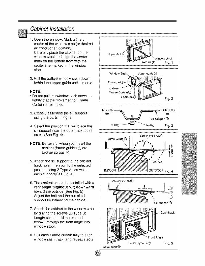
Cabinet Installation
1. Open the window. Mark a line oncenter of the window stool(or desiredair conditioner location).Carefully place the cabinet on the
window stool and align the centermark on the bottom front with thecenter line marked in the windowstool.
2. Pull the bottom window saslh down
behind the upper guide until it meets.
• Do not pull the window sash down sotightly that the movement of FrameCurtain is restricted.
3. Loosely assemble the sill supportusing the parts in Fig. 3.
4. Select the position that will place thesill support near the outer most pointon sill (See Fig. 4)
NOTE: Be careful when you install thecabinet (frame guides @ are
broken so easily).
5. Attach the sill support to the cabinettrack hole in relation to the selected
position using 2 Type A screws ineach support(See Fig. 4).
6. The cabinet should be installed with a
very slight tilt(about 1/2") downwairdtoward the outside (See Fig. 5).Adjust the bolt and the nut of sillsupport for balancing the cabinet
7. Attach the cabinet to the window stool
by driving the screws ®(Type B:
Length sixteen millimeters andbelow.} through the front angle intowindow stool,
8. Pull each Frame curtain fully to eachwindow sash track, and repeat step 2.
Upper Guide
Window stool
Front Angie Fig, 1
Window Sash
Foam-
Frame Cumin 0
Foam-pe@
_rew(Type A) Q
Sill suppo_Q
Front Angle
Screw(Type B)Q
_rew(Type B)
SillsuppodQ
Sashtrack

9. Attach each Frame curtain the window sash
using screws _Type C),(See Fig, 6)
CAUTION: DO NOT DRILL A HOLE IN THEBOSOM PAN,
The unit is designed to operatewith approximately 1/2" of water inbottom pan,
10. Slide the unit into the cabinet(See Fig, 7)
CAUTION: For security purpose, reinstallscrews(Type A) at cabinet's sides.
Screw(Ty_ A)
........Power cord
f
Screw(Type A)
11. Cut the foam-strip ® to the proper length
and insert between the upper window sashand the lower window sash.
(See Fig. 8)
F_m-Strip Q
12. Attach the window locking bracket @ witha type C screw (See Fig. 9)
Window locking bracket @
13. Attach the front grilte to the cabinet byinserting the tabs on the grille into the tabson the front of the cabinet, Push the grillein until it snaps into place. (See Fig,10)
14 Lift the inlet gdlle and secure it with a typeA screw through the front grille,(See Fig. 11)
15, Window installation of morn air conditioner
is now completed, See ELECTRICAL DATAfor attaching _wer cord to electrical outlet,
Fig, 10
Fig. 11

How to Use the Reversible,Inlet Grille
1. If you want to pull out the filter upward,open the inlet grille slightly. Turn inside outthe front grille.
Disassemble the inlet grille from the frontgrille with separating the hinged part byinserting a "--" type screw-driver tip.
Rotate the inlet grille 180 degrees andinsert the hooks into the lower holes of front
grille
Then, insert the filter. (See Fig.12, 13)
2 A_ach the front grille to the cabinet byinserting the tabs on the grifle into the tabson the front of the cabinet, Push the grille inuntil it snaps into place (See Fig.14)
!7 Fig. 12
Fig, 13
3. Lift the inlet grille and secure it with a typeA screw through the front grille.(See Fig. 15)
4 if you want to pull out the filter downward,use the reversible inlet grille withoutchange.(The grille is already assembled for thatway.)
Bectrical Data
Fig, 14
Fig. 15,
Line Cord Plug Use Wall Receptacle Power Supply
......._ l[)o r_otur'der ar_Y
_T J z/ circumstances out-./.._ or remove the Use 15 AM P time>-_J I grounding prong delay fuse or circuit
[..from the plug,
i breaker.Power supply €oid with3oprong grounding plug
USE OF EXTENSION CORDSBecause of potential safety hazards, we strongly discourage the use of an extension cord_However, if you wish touse an extension cord, use a CSA certifiediUL-listed 3-wire (grounding) extension _rd, rated 15A, i25V.
Standard 125V, 3-wire groundingr_eptacle rated 15A, 125V AC

Electrical Safety
(PLEASE READ CAREFULLY)
FOR THE USER'S PERSONAL SAFETY, THIS
APPLIANCE MUST BE PROPERI_ Y GROUNDED
The power cord of this appliance is equipped with a
three-prong(grounding) plug. Use this with a
standard three-slot(grounding) wall power
outlet(Fig. 16) to minimize the hazard of electricshock. The customer should have the wall
receptacle and circuit checked by a qualified
electrician to make sure the r_eptacle is properly
grounded,
PREFERRED METHOD
nsureFoper ground
exists _fore u_
Fig. 16
DO NOT CUT OR REMOVE THE
OUND) PRONG FROM THE POWERPLUG,
A. SITUATIONS WHERE THE APPLIANCEWILL BE DISCONNECTED ONLYOCCASIONALLY:
Because of potential safety hazards, we strongly
discourage the use of an adapter plug. However, if
you wish to use an adapter, a TEMPORARYCONNECTION may be made. Use ULqisted
adapter, available from most local hardware
store(Fig. 17). The large slot in the adapter must bealigned with the large slot in the receptacle to
assure a proper polari_ connection.
CAUTION: A_aching the adapter ground terminal b
the wall receptacle _ver screw does not ground the
appliance unless the cover screw is metal, and not
insulated, and the wall receptacle is grounded
through the house wiring.
The customer should have the circuit checked by a
qualified electrician to make sure the
receptacle is properly grounded.
Di_onnect the power cord from the adapter, using
one hand on each_ Otherwise, the adapter ground
terminal might break DO NOT USE the appliance
with a broken adapter plug,
B. SITUATIONS WHERE, THE APPLIANCEWILL BE DISCONNECTED OFTEN.
Do not use an adapter piug in these situations.
Unplugging the power _rd fr_uent]y can lead to
an eventual breakage of the ground terminal Thewail power outlet should be replaced by a
three-slot(grounding) outlet instead.
Metal screw
Fig. 17
USE OF EXTENSION CORDS
Because of potential safety hazards, we strongly
discourage the use of an extension cord. However,
if you wish to use an extension cord, use a CSA
certified/UL4isted 3-wire(grounding) extension cord,rated 15A, 125V,
fore you for
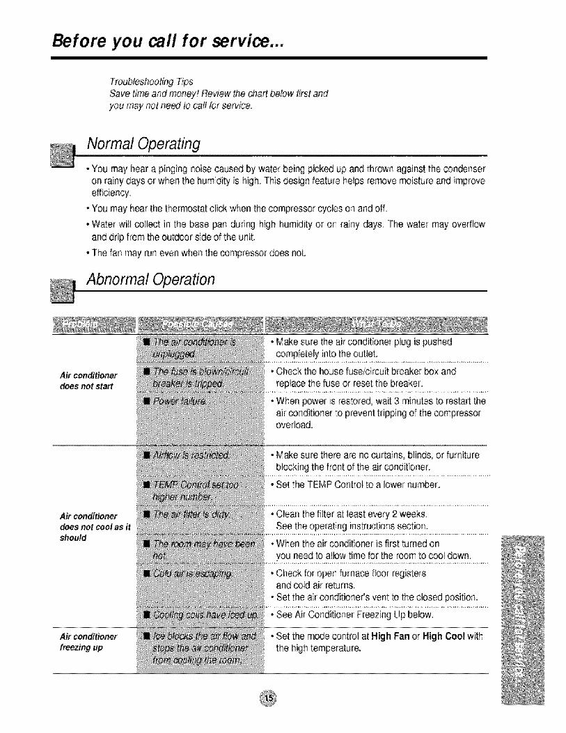
Troubleshooting TipsSave I time and money! Review the chart below first andyou may not ne_ to cat! for service.
Normal OPerating
• You may hear a pinging noise caused by water being picked up and thrown against the condenseron rainy days or when the humidity is high. This design feature helps remove moisture and improveefficiency.
• You may hear the thermostat click when the compressor cycles on and off.
• Water will collect in the base pan during high humidity or on rainy days, The water may overflow
and drip from the outdoor side of the unit,
• The fan may run even when the compressor does not.
Abnormal Operation
Air conditionerdoesnot start
Air conditionerdoesnot cool as itshould
Air co,ndition_
• Make sure the air conditioner plug is pushedcompletely into the outlet.
Check the house fusdcircuit breaker box and
replace the fuse or reset the breaker,
When power is restored, wait 3 minutes to restart theair conditioner to prevent tripping of the compressoroverload.
Make sure there are no curtains, blinds, or furniture
blocking the front of the air _nditioner.
Set the TEMP Control to a lower number
. Clean the filter at least every 2 weeks.See the operating instructions s_tion.
• When the air conditioner is first turned on
you need to allow time for the room to cool down.
• Check for open furnace floor registersand cold air returns.
• Set the air conditioner's vent to the closed position.
• See Air Conditioner Freezing Up below,
• Set the mode control at High Fan or High Cool withthe high temperature,