m i!flm - digital library/67531/metadc618868/m2/1/high... · a suction vortex exists at the inlet...
TRANSCRIPT
--lwest
PNNL-13039UC-2030
m
i!fl<mu
,::-,:.::},;.,,:. ;,:.J, : -,. .’ Effects of Crust Ingestion on Mixer Pump:.?,.,.... ..,>.-,:,::.,-:.,.“,:,..-,.>,-.. ~,: Performance in Tank 241-SY-101:.....,,”. ,,..,.,...:... Workshop Results...... “...... ..

DISCLAIMER
This report was prepared as an account of work sponsored by an agency of theUnited States Government. Neither the United States Govermnent nor any agencythereof, nor Battelle Memorial Institute, nor any of their employees, makes anywarranty, express or implier$ or assumes any legal liability or responsibilityfor the accuracy, completeness, or usefulness of any information, apparatus,product or process disclose~ or represents that its use would not infringeprivately owned rights. Reference herein to any specific commercial produc~process, or service by trade name, trademark manufacturer, or otherwise does notnecesuily constitute or imply its endorsement recommendation, or favoring by theUnited States Government or any agency ther+ or Battelle Memoriai Institute. Theviews and opinions of authors expressed herein do not necessarily state or reflectthose of the United States Government or any agency thereof.
PACIFIC NORTHWEST NATIONAL LABORATORYoperated byBATTELLE
for theUNITED STATES DEPARTMENT OF ENERGY
under Contract DE-A C06- 76RL0 1830
Printed in the United States of America
Available to DOE and DOE contractofi from theOflice of Scientific and Technical Information, P.O. Box 62, Oak Ridge, TN 37831;
prices available from (615) 576-S401.
Avaifable to the pubfic from the National Technical Information Service,U.S. Department of Commerce, 5285 Port Royal Rd., Springfield, VA 22161
@ This document was printed on recycled paper.(9/97)

DISCLAIMER
Portions of this document may be illegiblein electronic image products. Images areproduced from the best available originaldocument.

(a) California Institute of Technology
PNNL-13039UC-2030
Effects of Crust Ingestion on MixerPump Performance in Tank241-SY-I 01: Workshop Results
PA MeyerCW StewartCE Brennen(a)
September 1999
Prepared forthe U.S. Department of Energyunder Contract DE-AC06-76RL0 1830
Pacific Northwest National LaboratoryRichland, Washington

Summary
In August 1999, a workshop was held at Pacific Northwest National Laboratory to discussthe effects of crust ingestion on mixer pump performance in Hanford Waste Tank 241-SY-101.The main purpose of the workshop was to evaluate the potential for crust ingestion to degrademixing and/or damage the mixer pump. The need for a previously determined 12-inchseparation between the top of the mixer pump inlet and the crust base was evaluated.Participants included a representative from the pump manufacturer, an internationally knownexpert in centrifugal pump theory, Hanford scientists and engineers, and operational specialistsrepresenting relevant fields of expertise.
The workshop focused on developing an understanding of the pump design, addressing thephysics of entrainment of solids and gases into the pump, and assessing the effects of solids andgases on pump performance. The major conclusions are summarized as follows:
●
●
●
●
●
Entrainment of a moderate amount of solids or gas from the crust should not damage thepump or reduce its lifetime, though mixing effectiveness will be somewhat reduced.
Air binding should not damage the pump. Vibrations due to ingestion of gas, solids, andobjects potentially could cause radial loads that might reduce the lifetime of bearings andseals. However, significant damage would require extreme conditions not associated withthe small bubbles, fine solids, and chunks of relatively weak material typical of the crust.
The inlet duct extension opening, 235 inches from the tank bottom, should be consideredthe pump inlet, not the small gap at 262 inches.
A suction vortex exists at the inlet of all pumps. The characteristics of the inlet suctionvortex in the mixer pump are very hard to predict, but its effects likely extend upwardseveral feet. Because of this, the current 12-inch limit should be replaced with criteriabased on actual monitored pump performance. The most obvious criterion (in addition tocurrent operational constraints) is to monitor discharge pressure and cease pump operationif it falls below a predetermined amount.
There are no critically necessary tests to prove pump operability or performance beforeinitiating the transfer and back-dilution sequence.
...111


Contents
summary ...........................................................................................................................................111
1.0
2.0
3.0
4.0
5.0
6.0
Introduction ........................................................................................................................... 1.1
Workshop Description .......................................................................................................... 2.1
SY-101 Mixer Pump Design and Operation ......................................................................... 3.1
Effects of Crust Ingestion on Mixer Pump Pefiomance ...................................................... 4.1
The Physics of Crust Entrainment ........................................................................................ 5.1
Recommendations and Conclusions ..................................................................................... 6.1
Appendix A:
Appendix B:
Workshop P~icipants ......................................................................................... A.1
Letter flom C. E. Bremen .....................................................................................B.l
Figures
1.1 Crust Base Interfering with Mixer Pump Operation ............................................................. 1.13.1 Components of Mixer Pump System .................................................................................... 3.24.1 Performance Breakdown Due to Gas Ingestion in a Centrifugal Pump ............................... 4.1
v
1.0 Introduction
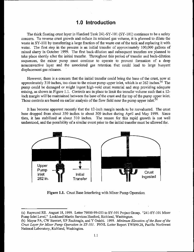
The thick floating crust layer in Hanford Tank 241-SY-101 (SY- 101) continues to be a safetyconcern. To reverse crust growth and reduce its retained gas volume, it is planned to dilute thewaste in,SY-101 by transfeming a large fraction of the waste out of the tank and replacing it withwater. The first step in the process is an initial transfer of approximately 100,000 gallons ofmixed slurry in October 1999. The first back-dilution and subsequent transfers are planned totake place shortly after the initial transfer. Throughout this period of transfer and back-dilutionsequences, the mixer pump must continue to operate to prevent formation of a deepnonconnective layer and the associated gas retention that could lead to large buoyantdisplacement gas releases.
However, there is a concern that the initial transfer could bring the base of the crust, now atapproximately 310 inches, too close to the mixer pump upper inlet, which is at 262 inches.(a) Thepump could be darnaged or might ingest high-void crust material and stop providing adequatemixing, as shown in Figure 1.1. Controls are in place to limit the transfer volume such that a 12-inch margin will be maintained between the base of the crust and the top of the pump u er inlet.These controls are based on earlier analysis of the flow field near the pump upper inlet. 8J’
It has become apparent recently that the 12-inch margin needs to be reevaluated. The crustbase dropped from about 350 inches to about 300 inches during April and May 1999. Sincethen, it has stabilized at about 310 inches. The reason for this rapid growth is not wellunderstood, and the possibility of a similar event prior to the initial transfer must be allowed for,
UpperPumpInlet262 in.
Figure 1.1. Crust Base Interfering with Mixer Pump Operation
(a) Raymond RE. Augnst 18, 1999. Letter 79000-99-053 to SY-101 Project Group. “241-SY-101 MixerPump Inlet Level.” Lockheed Martin Services Hanford, Richland, Washington.
(b) Meyer PA, CW Stewart, KP Recknagle, and Y Onishi. 1999. Minimum Elevation of the Base of the
Crust Layer for Mixer Pump Operation in SY-101. PNNL Letter Report TWS99.28, Pacific Northwest
National Laboratory, Richland, Washington.
1.1

If the crust base were to drop again by a similar amount, even a small transfer would violate the12-inch margin. In addition, the technical basis for the 12-inch margin needs to be revisited. The12-inch separation was determined from a simplistic model that compared the shear stresses onthe crust base induced by the pump inlet suction flow field with the assumed strength of the crustbase material.
An expert workshop was held at Pacific Northwest National Laboratory on August 4, 5, and10, 1999, to reexamine the 12-inch separation control. Its purpose was to evaluate the potentialfor crust ingestion to degrade mixing and/or to damage the mixer pump. Attendees includedexperts in the following areas:
●
●
●
e
●
●
*
●
●
Centrifugal pump design, theory, and operationFluid mechanics, multiphase flow, mixing, sludge mobilizationThermal sciences, transport phenomena, heat transferFlammable gas safety, nuclear safety and licensingTank waste configuration and propertiesTank farm and mixer pump operationsProcess EngineeringMechanical DesignElectrical Engineering
In addition, engineers familiar with the specific design details of the mixer pump and arepresentative from the pump manufacturer were present. The workshop focused on the pumpdesign, the physics of entrainment of solids and gases into the pump, and the effects of solids andgases on pump performance.
This report summarizes the information presented and discussed during the workshop and themajor conclusions. Section 3 describes the structure of the workshop and presents the issues thatwere addressed. Sections 4-6 contain a summary of the information-gathering phase of theworkshop: Section 4 addresses pump design and operation, Section 5 the effects of solids andgas on pump performance, and Section 6 the physics of crust entrainment. Section 7 presents themajor conclusions and recommendations developed during the workshop. Appendix A lists theworkshop participants, and Appendix B contains a letter of findings by Professor ChristopherBrennen from the California Institute of Technology.
1.2

2.0 Workshop Description
The workshop attempted to develop consensus-based, technically defensible answers to thefollowing questions:
. Is the existing 12-inch separation requirement betieen the bottom of the crust and the topof the pump inlet sufficient to ensure effective mixer pump operation?
. Is 12-inch separation necessay, or is there a better alternative method to ensure effectivemixer pump operation?
. Can the pump survive temporarily ingesting crust, or must crust ingestion be avoidedaltogether?
The format used to achieve answers to these questions involved identi~ing key questions,addressing essential issues, and capturing information in the form of questions, ideas, andconclusions.
It is important to carefully define what is meant by degraded pump operations and crustingestion. For the purposes of the workshop discussion, these were defined as follows:
Degraded Pump
●
●
●
Reduction in mixing efficiency due to the presence of solids or gas in the process stream.The net effect of reduced efficiency would be a reduction in pump discharge pressureresulting in less jet momentum and hence less mobilization of the settled solids layer.
Reduction in allowable pump operating time. Because operating time is limited by oiltemperature, degraded cooling due to gas ingestion would result in a decrease inoperating time. This also would reduce mobilization of settleddependent, to some extent, on mixer pump run time.
Permanent damage to the pump or operational difilculties requiringpump operating procedures.
Mixer Pump Effectiveness:
The ability of the mixer pump to mitigate buoyant displacementpreventing the buildup of a nonconnective layer at the bottom of the tank.
solids because it is
disruption of normal
GREs by adequately
Crust Ingestion
Entrainment of solids, bubbles, or bulk material (matrix of gas/liquid/solid) into the mixerpump inlet. This could also include ingestion of foreign materials. The following key questionswere identified and addressed extensively during the workshop:
. Under what conditions is crust ingestion likely?
. What will be the effects of crust ingestion on mixer pump effectiveness?
2.1
. What separation is required to maintain effective mixer pump operation?
. Are lab-scale or fill-scale tests required?
. Are there monitoring activities, operational approaches, or response actions that will helpmaintain effective mixer pump operation?
● Are there other issues to be considered?
The following technical categories were used as working issues throughout workshopdiscussions:
●
●
●
●
Air Binding. This relates to the trapping or accumulation of gas in the mixer pump.Accumulation of solids was also considered.Performance Breakdown. This refers to hydrodynamic breakdown across the pumpimpeller resulting in performance degradation.Heat Transfer. This relates to reduction in motor cooling resulting from entrained crustmaterial.Entrainment. This refers to the process, external to the pump, whereby crust material isingested into the pump.
2.2

3.0 SY-101 Mixer Pump Design and Operation
Figure 3.1 is a schematic of the relevant components of the mixer pump. The waste entersthe inlet, passes through the impeller, and then enters the volute. Rather than being discharged,the waste enters the annular cooling jacket around the oil-filled motor casing by way of two largecrossovers. After pefiorming its cooling fimction in the annular jacket, the waste is dischargedthrough the nozzles.
A tailpipe, or inlet duct extension, was added as a structural member to prevent the pumpcolumn breaking during installation. It is 235 inches from the tank bottom and has no hydraulicfiction. A small gap exists between the tail pipe and the upper pump inlet. The original 12-inch separation was measured from the top of this gap (262 inches from the bottom of the tank)to the crust base. The gap is severely obstructed by bolt blocks. There is no hydraulic reason forthe small gap; it was provided to prevent forces on the wearing ring at the pump inlet. There aretwin discharge volutes, each with its own crossover. The cooling jacket is a common plenum forboth volute discharge streams. The motor stator and rotor are immersed in oil, which swirlsaround the casing by rotation of the rotor and shaft. There is no way to add additional oil. As-built elevations from the tank bottom are available for all the major components of the pump.
The pump was originally designed for short-term operation (two-year design life). It hasnow operated six years. The primary catastrophic failure mode is oil loss through the seals. Thepump has both inboard and outboard seals; both need to fail in order to lose oil. Seal failurewould be accelerated by vibrations induced by bearing wear. The oil lifetime is estimated to beabout 20 years in the SY-101 radiation environment, The oil temperature limit is stated as 21O”Fby the pump manufacturer. The temperature is limited operationally to 190°F. One study of seallife determined that lifetime of seals is 9 + 3 years. Temperature effects are deemed moreimportant than radiation dose with regard to seal life. Thermal cycling effects on seal life havenot been studied.
There are places where water can be introduced into the mixer pump system: a burrowingring below the discharge nozzles that can inject about 30 gpm vertically downward and a high--pressure heel-flush port in the nozzles that operates at very low flow rate. A suction clearingring introduces water into the bell mouth at about 30 gpm. The annular jacket flush wasdesigned to decontaminate the pump internals prior to removal. The flush line is attached to a 2-inch ring header that has four l-inch lines entering the annular jacket; the annular jacket flushcan operate at about “140gpm. The ring header has one 3/16-inch-diameter hole that wasdesigned to bleed trapped air out of the pump during installation. It is not known whether thishole is now plugged with waste. The ring header sees pump discharge pressure at all timesduring pump operation so it is possible that the hole is clear. The annular jacket flush wouldprobably not flush the entire rotor/inlet because the passages between impeller blades are quitelarge and the water would likely find a preferred path. The annular jacket was flushed twiceduring May 1999 with no measurable effect on pump monitoring data.
3.1

OIL-FILLEDTANK
--lMOTOR
/- IMPELLER
LINES
/-- ANNULARJACKET
? 3/16 in. HOLE
L
.f
‘\2 IN. RINGHEADER-—--. ——-. .---- —__ -————
—----- —- ——----- —-------
FOUR 1 in.
o3
i
NOZZLES
k-TWO LARGECROSSOVERS
/
TrNLETDUCT
@ HEEL FLUSHA
(-30 GPM)
T--b@
o2 SUCTION CLEARINGFLUSH (-30 GPM)
o3 ANNULAR JACKETFLUSH (- 140 GPM)
Figure 3.1. Components of Mixer Pump System
3.2

The following operational shutdown criteria and alarms are specified for the pump:
● Motor current 1.4 times expected amps, alarm at 1.2. Motor oil temperature at 225”F, alarm and shutdown at 190”F. Motor oil moisture indication (conductivity sensor). Pump column strain gauge at 194 micro-inctiinch● Pump column gas pressure 7 psig, alarm at 9 psig. Discharge pressure operating limit.
The primary indication of nozzle plugging or entrainment of solids or gas would be changesin nozzle discharge pressure. The motor oil temperature generally reaches 190”F in about 25minutes of operation. During pre-installation testing in water, the pump could operateindefinitely without reaching 190”F. The reason for the higher temperatures in the tank isthought to be the larger current required to pump waste with a much higher specific gravity andviscosity than water.
3.3
4.0 Effects of Crust Ingestion on Mixer Pump Performance
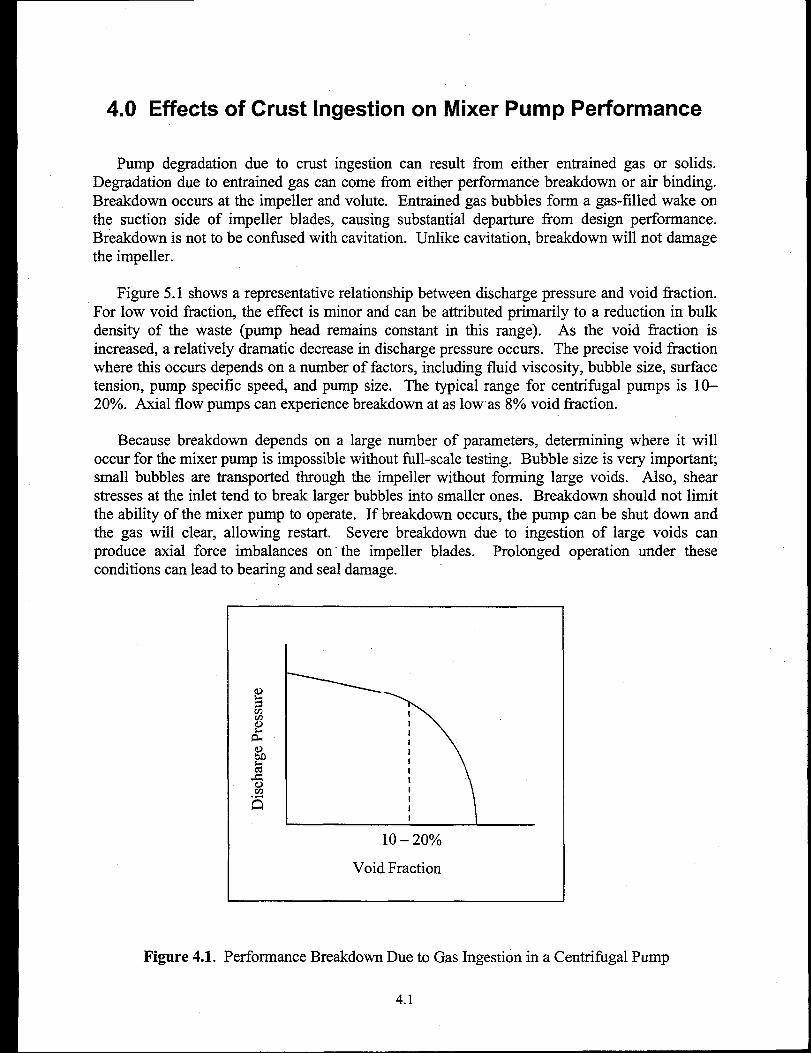
Pump degradation due to crust ingestion can result from either entrained gas or solids.Degradation due to entrained gas can come from either petiormance breakdown or air binding.Breakdown occurs at the impeller and volute. Entrained gas bubbles forma gas-filled wake onthe suction side of impeller blades, causing substantial departure horn design performance.Breakdown is not to be confised with cavitation. Unlike cavitation, breakdown will not damagethe impeller.
‘Figure 5.1 shows a representative relationship between discharge pressure and void fkaction.For low void fraction, the effect is minor and can be attributed primarily to a reduction in bulkdensity of the waste (pump head remains constant in this range). As the void fraction isincreased, a relatively dramatic decrease in discharge pressure occurs. The precise void fi-actionwhere this occurs depends on a number of factors, including fluid viscosity, bubble size, stiacetension, pump specific speed, and pump size. The typical range for centrifugal pumps is 10-20Y0. Axial flow pumps can experience breakdown at as lowas 8°Avoid fraction.
Because breakdown depends on a large number of parameters, determining where it willoccur for the mixer pump is impossible without fill-scale testing. Bubble size is very important;small bubbles are transported through the impeller without forming large voids. Also, shearstresses at the inlet tend to break larger bubbles into smaller ones. Breakdown should not limitthe ability of the mixer pump to operate. If breakdown occurs, the pump can be shut down andthe gas will clear, allowing restart. Severe breakdown due to ingestion of large voids canproduce axial force imbalances on- the impeller blades. Prolonged operation under theseconditions can lead to bearing and seal damage.
Figure 4.1.
IIIIII
I 1I I I
10 – 20%
Void Fraction
Performance Breakdown Due to Gas Ingestion in a Centrifugal Pump
4.1
Air binding occurs when a pocket ofgasis oftrapped inthepurnp internals. Air bindingoccurring at the impeller is similar to the pefiormance breakdown phenomena. However, if theimpeller is air-bound, the pump cannot be started because the blades are not contacting any fluid.This type of air binding would not be possible for the mixer pump unless the entire inlet, volute,and cooling jacket were intentionally air-filled. This would have been nearly the situation uponinitial pump installation and was the reason for adding the small hole in the ring header. A morelikely gas buildup scenario could occur in the annular cooling jacket, which provides aseparation chamber for the gas voids in the waste that are processed by the pump. The degree ofgas buildup depends on inlet void fraction, and the amount of flow (if any) through the smallhole in the ring header will also affect the buildup of gas. An as-yet undetermined amount of gasbuildup in the cooling jacket is certain to occur. The primary effect of air binding or gas buildupin the annular cooling jacket would be reduction in motor cooling. This would result in faster oiltemperature heatup and a shorter run time.
Entrained solids can have several effects on mixer pump performance. Fine solids, which arecarried with the fluid, will increase the bulk specific gravity, which requires additional power topump. This would cause the pump to draw additional current, resulting in faster oil temperatureheatup and reduced run time. Solids could also build up in the annular cooling jacket, whichcould act like a settling chamber. As with accumulation of gas, the degree of settling in thecooling jacket would depend on solids fraction, waste physical properties, solids settling times,fluid residence time in the annular jacket, and the degree of turbulence. The primary effect ofsolids buildup in the cooling jacket would be degraded cooling due to loss of heat transfercontact area between the liquid waste and the motor casing. The annular jacket flush operationshould clear any settled solids.
Finally, if large chunks of hard solids or foreign objects enter the mixer pump, impact withthe impeller blades would result in sudden load imbalances that could damage the bearings. Thisis not thought to be a major concern in SY-101 for two reasons. First, it is very unlikely thatforeign objects are lodged in the lower region of the crust. “The base of the crust is newlyformed, and foreign objects likely would have sunk to “the bottom of the tank during violentrollovers before the mixer pump was installed. Second, the crust base material is believed to berelatively weak. The impact of a discrete portion of this material with the impeller blade isanalogous to a week ball of mud hitting a wall. The likelihood of material with high strengthbeing liberated from the crust and ingested is considered very unlikely. Additionally, the maininlet is oriented downward. The upward velocities near the inlet are insufficient to entrainsubstantial sized debris.
4.2
5.0 The Physics of Crust Entrainment
The degree to which the crust material will be ingested into the mixer pump depends on thenature of the inlet vortex and its interaction with the crust base. An inlet vortex always forms atthe inlet of a submerged pump. Because the vorticity is essentially conserved, the vortex mustterminate at a surface. A vortex from a pump submerged in a liquid with a free surface will oftenentrain air, or ventilate. Significant performance degradation generally occurs when the inletvortex ventilates because air is drawn directly into the inlet. Whether the vortex ventilatesdepends on several factors. The submergence of the inlet is important. The smaller thesubmergence, the more likely ventilation will occur. The critical submergence (the submergenceat which the vortex cannot ventilate) scales roughly with the inlet diameter. Inlet vortices asmuch as 8–1Odiameters below the surface may ventilate. The critical submergence also dependson the vortex strength. The strength of an inlet vortex is design-dependent. However, as a rule,the strength will be minimized when the pump is operating at its design flow rate. As the flowrate is reduced, the inlet vortex becomes stronger. Pumps operating at very low flow rate willhave the strongest inlet ‘vortices. The mixer pump in SY-101, when operating at 1000 rpm, isoperating at just below its design flow rate. This means the inlet vortices are not as strong asthey could be; however, there is no way of knowing how strong they actually are without full-scale testing.
Solid surfaces such as sheets of floating plywood can be used to prevent vortex ventilation.Therefore, the 10-foot-thick crust in SY-101 should effectively eliminate vortex ventilation.However, little is known about the interaction of inlet vortices with a weak solid surface such asthe crust base. It is reasonable to assume that the inlet vortices have, to some degree, alreadyeaten away some of the crust base near the pump. Because the pump is operating close to itsdesign point, the vortex will not be strong enough to ventilate until the base of crust gets near theinlet. Even then, ventilation would be impossible unless there is abundant gas available. Unlessthe vortex ventilates, it probably cannot pull enough bubbly material into the inlet to cause aproblem. The downward velocity inside the vortex core is probably not much greater than thedownward velocity away from the vortex. To be conservative, however, it is best to assume thatthe vortex will pull some small amount of crust gas into the pump.
The chance of inlet plugging due to crust entrainment is very slight. The lowest part of thecrust is likely quite slushy, as observed during operation of the mechanical mitigation arm in lateMay, and therefore should not plug. The impeller will break up small chunks of crust material.Any large chunks of crust would. be filtered out by hardware surrounding the main inlet.Additionally, the crust material, which is strong enough to plug the inlet, is unlikely to breakaway from the crust and get into the pump by virtue of its own strength. If inlet plugging were tooccur, it would be immediately detectable fi-omdischarge pressure or motor amperage.
5.1

Throughout
6.0 Recommendations and Conclusions
the workshop, whenever a consensus on an important issue wascaptured as a conclusion or recommendation. These are summarized as follows:
1.
2.
3.
4.
5.
6.
7.
8.
9.
reached it was
Gas entrainment into the small gap is not a concern because the majority of the flow entersthe pump through the main inle~ For all practical purposes, the gap-does not act as an inlet.The original 12-inch separation was based on the distance between the crust base and thesmall gap. It is more meaningful to consider the distance between the crust base and the maininlet. The main inlet elevation is 235 inches from the tank bottom; the small gap is 262inches from the bottom.
Entrainment of a moderate amount of solids or gas from the newly formed lower region ofthe crust does not significantly damage the pump or reduce its lifetime, though mixingeffectiveness would be somewhat reduced.
Pump performance degradation is not equivalent to pump darnage. For small void fractions,degradation means reduction in discharge pressure, which is, from a hydraulic point of view,equivalent to operating the pump at lower speed. Degradation can eventually lead to pumpdamage if it is severe enough and continues for an extended period of operation measured inhours.
There will be obvious and adequate precursors to pump darnage by performance degradation.Discharge pressure will be significantly reduced and oil heatup rate will significantlyincrease.
Air binding should not damage the pump. Vibrations due to ingestion of air/solids/objectspotentially could cause radial loads that might reduce the lifetime of the bearings and seals.However, this would require extreme conditions not associated with small bubbles, finesolids, and weak chunks.
The pump has operated for about 500 hours since installation and thus is very young in termsof the normal operating lifetime for similar pumps.
Bearing failure leading to seal darnage is the primaryfailure would not occur suddenly even under extremetake several hours, not minutes.
failure mode of the pump. Bearingconditions. Failure would generally
There has always been some gas in the mixed slurry. Hence, technically speaking, the pumphas been operating in a somewhat degraded mode all along. Recent changes in slurry voidfraction have been readily apparent in discharge pressure.
The process of transfer and back-dilution does not increase the risk of ingestion of foreignobject debris (FOD). The lower portion of the crust has been recently formed, so there is littlereason to suspect FOD would be embedded in it.
6.1

10. The characteristics of the inlet suction vortex are very hard to predict but can be assumed toaffect the base of the crust. Because of this, the 12-inch limit is ineffective and should bereplaced with criteria based on monitored pump performance. The most obvious criterion isto monitor discharge pressure and stop pump operation if it falls below a predeterminedamount.
11.
12.
13,
14<
The minimum allowable discharge pressure for pump operation should be based on analysisof the mobilization and mixing of settled solids in the tank.
If pump performance measures deviate from the norm, then operation should cease pendingevaluation. There is no need to develop a detailed degraded pump operating criteria beforethe fact.
It is not necessary to run the pump as often as in the past during an ongoing transfer andback-dilution campaign because the potential for serious buoyant displacement GREs will beeliminated before a dangerous amount of gas can accumulate. Therefore, if significantdegradation occurs during operation, the frequency of operation can be reduced. Thereduced frequency should depend on analysis of gas generation and rate of retention.
There are no critically necessary tests to perform before the transfer and back-dilution stepsare initiated. Even though they are not necessary, several potential tests have been identified:
. Inject air into the inlet flush jets to assess the effect of air ingestion. The potential valuewould be to demonstrate that the pump could operate with significant gas entrainment.
. Perform scaled tests to assess vortex formation under a crust and the effect of vortices ona crust.
● Monitor thermocouple uncovery at several different pump speeds and correlate wastemobilization with discharge pressure. This could verify experimentally the minimumallowable discharge pressure.
6.2
. Pump water down the annular jacket flush during pump operation and see if oil heats upmore slowly. This would help determine whether some air holdup is occurring in theannulus.

Appendix A
Workshop Participants

Name
JR BiggsJM GrigsbyCE HansonCP ShawFA SchrnordeGJ GauckGD JohnsonNW KirchRE RaymondFF ErianZA AntoniakPA MeyerWL KuhnCW StewartW HaentjensCE Brennen
Appendix A: Workshop Participants
Area of Expertise
Tank Farm OperationsNuclear Safety & LicensingMechanical Engineering DesignPump DesignTank Farm OperationsPlant EngineeringFlammable Gas SafetyProcess EngineeringElectrical EngineeringMultiphase FlowHeat TransferFluid MechanicsTransport PhenomenaThermal Fluids ScienceCentrifugal PumpsCentrifugal Pumps
Organization
E2 Consulting Engineers IncG&P Consultants IncCogema Engineering CorpCogema Engineering CorpLockheed Martin Hanford CorpLockheed Martin Hanford CorpLockheed Martin Hanford CorpLockheed Martin Hanford CorpLockheed Martin Hanford CorpPacific Northwest National LaboratoryPacific Northwest National LaboratoryPacific Northwest National LaboratoryPacific Northwest National LaboratoryPacific Northwest National LaboratoryHazleton Pump CoCalifornia Inst. of Technology
A.1

Appendix B
Letter from Christopher Brennen

Perry Nieyer
36001 ive Tree Lane
Sierra Madre, Cal. 91024
.iu~t,st 17, lgg’J
Fluid Dynamics GroupPacific Northwest. Nat.ional Lal)orah-y
Report on Aug.4, 5, 1999, Visit
by
Christopher E. BrennenCa.hfornia Institute of Technology,
Pasadena. CA 91125
Purpose
The purpose of my consulting ~isit to Hanford. hosted by the Fluid DynamicsGroup, Pacific Northwest National Laboratory, was to advise r.hern on issuesperkining to how the mixer pump in the 101 waste tank would perform uponingestion of crust. On the first clay I visited with Perry Meyer, Zen Antoniak.Charles Stewart and Craig Shaw for an orientation on t,he wasr.e tank and themixer pump. On the second we transitioned into a workshop with many addi-tional participants to study the issues in detail.
In general, these experiences led me to conclude that the staff are addressingthe complex scientific and engineering issues of mixer pump crust ingestion in athorough, constructive and realistic manner. I believe I was able to add some-thing to the discussion aa a rcs..dt of my previous experience in a. wide varietyof pump problems and mult.iphase flow issuea. The interactive discussions atthe pump workshop were particularly constructive and resulted in a number ofspecific technicaf directives and conclusions which were summarized in a reportwhich was prepared during the workshop (it. is currently only awilable to me inrough form but the essence of each point is clear). Each of these comments andconclusions was reached after carefu I discussion which incorporated commentsfrom many perspectives. [ agrecded \vit]l all of the com[nent.s and conc]u~ions
and believe r.hey form a sound basis for a re-examination of the waste removalstrategies.
It would therefore not be particularly valuable for this report. r.o re-i terateall of the clet.aikd discussion whid led to the conclusions in the report since J
regard that report as, in effect, comticut ing part of my report. However, it u ta>be valuable to r-iterate a few basic issues to which I contributed in a substal]t.ialway.
Some Specific Issues
Q In my experience it is of critical importance in an: turbomachinery issue iotake the time to fully understand the complicated geometry of the devicein question. Thanks to Craig Shaw we did this in this case and, as aresult, several new perspectives emerged. I continue to urge attention tothe details of the mechanics and fluid dynamics of the mixer pump and itsprincipal components, namely the induction motor in its oil-filled cavity,the bearings, the seals, the cover gas, the annular waste-fluid-filled jacketaround the oil cavity, the double volute and the impeller in addition to thecomponents modified or added for use in SY-101, namely the inlet duct.the downcomers and the nozzles. A rough schematic of these componentsis attached.
● I continue to recommend that the pump mamtfacturer be pressed to pro-vide as much knowledge as they have on the performance of this pumpand experiences with che pump in the field. It wonld be my j udgementthat the pump is most likely to fail because the seal at the bottom ofthe oikcavky begins to leak and the oi] is lost., Since there is no way torepienish the oil this wili mean the end of the pump as an operable &Iit..It. is important to emphasize that it, is only a question of time until thishappens. Consequently any field experience with these pumps which themanufacturer could provide would be valuable in evaluating the possiblefailure modes and, perhaps, devising ways to extend the pump life.
● R is also important to emphasize that this is a rugged sump pump designedto ingest slot of solids and, perhaps, gases without signicant damage.Indeed the mixer pump may well have ingested snbsta.nt.ial solids duringthe initial r-nixing during Phase B tests. It seems to me quite unlikely thatingestion of crust material, particularly from the bottom of the crust, isIikely to cause much harm to the pump impeller or vohtte.
● During our discussions, I indicated that the accumulation of gas in theannular cooling jacket (the high point of the waste flow route) was a morelikely cause for concern. Perhaps the accumulation of gas in this spacelms always ca.usecl a decrease in the heat transfer from the oil-filled cavityand therefore the unexpectedly high rate of temperature increase in the oilduring pump runs. This would be a concern if fut ure use ingested greatervolume fractions of gas and resulted in even more gas ,accummulation inthe annular jacket - leading to shorter pump runs due to shut down at thered-lined oil temperature.
●
●
The fluid mecknics of gas ingestion were also discussed at length and [introduced the concept. of intake vortex ventilation wbich had not bwwrecognized by the group. In the case of water intakes (for example topower plant cooling systems) this phenomena determines the minimumsubmergence at which the intake can be operated. Extensive literatureexists on this subject. However. I know of little experience which applieswhen there is a floating crust on top of the liquid. I suspect that thevort<ex will sti!l form (its strength increases as the pump operating pointis lowered below the design point) aud will impinge on the bottom of thecrust layer. But there is little to guide us on the submergence at whichthe vortex could begin to ingest solids/gases from the crust which wouldthen travel down the vortex core into the pump inlet. This coulcl happeneven if the clearance between the pump suction and the crust bottom wereseveral suction diameters. I recommend that some basic research programbe conducted at a model scale to identify the phenomena that occur witha floating crust. Quantitatively the results might be difficult to scale up toprototype size; however. qualitatively it would be of value to know whatthe basic fluid dynamic processes are. For example, it might be valuableto determine -whether the intake vortex might in fact help by scouring ~deating away at the bottom of the crust in the vicinity of the pump. Inmy view the issues with respect to the behavior of the intake are the leastpredictable of the central issues in question.
In the light of the above uncertainit.ies, it is not. clear to me that. thecurrent. 1X7?ch clearance constraint makes much se]w. 1 do t.])ink thatmonitoring the pump head and placing a const raint on the amount of headdegradation to be tolerated is much more sensible. One suggestion mightbe to establish an ah-n at, say, 10/drop and an automatic shutdown at40/n~aintain some elevation clearance in addition. Since I do not believethat any solids or gases ingested through the “snial] gap” at the originalsuction bellmouth could cause a problem, a prudent additional constraintmight be to maintain some minimum clearance between the bottom of thesuction duct and the bottom of the crust. - say one diameter of the suctionduct. Of course, throughout it. is critical to maintain the current limits onoil temperature and motor amps.
I emphasize that these are only a few of the issues which are covered in thepump workshop report which should be appended to this letter report.

No. of
C@S
Offsite
2 OffIce of Scientific and TechnicalInformation
C. E. Brennan360 Olive Tree LaneSierry Madre, CA 91024
Onsite
17 PHMC Team
W. B. BartonR. E. Bauer (3)J. R. BiggsR. J. CashJ. M. Grigsby (3)B. K. HamptonC.E. HansonG. D. JohnsonN. W: KirchL. J. KlippSR. E. RaymondC.P. ShawF. A. Schmorde
PNNL-13139UC-2030
Distribution
R2-11S7-73S7-07S7-73R1-44G1-24S7-70S7-73R2-11S7-73S7-70R3-74T4-08
Distr. 1
No. of
C@=
3 DOE Richland O~erations Office
C. A. Groendyke (3) H6-60
19 Pacific Northwest National Laboratory
J. M. BatesS. Q. BennettJ. W. Brothers (4)C. E. EnderlinW. L. KuhnP. A. Meyer (2)C. W. Stewart (3)B. E. WellsInformation Release (5)
K7-15K7-90K9-20K7-15K7-15K7-15K7-15K7- 15K1-06