m 700(x) - mettler toledo balances & scales for · pdf filethe m 700(x)s version with...
TRANSCRIPT

Safety informationand short description ENG
M 700(X)

WarrantyDefects occurring within 1 years from delivery date shall be remedied free of charge at our plant (carriage and insurance paid by sender).Sensors, fittings, and accessories: 1 year.
©2005 Subject to change without notice
TS-201.011-MTX03 240205

ENG-3
Safety informationInformation on installation
Be sure to read and observe the following instructions!The device has been designed in accordance with the state of the art and complying with the applicable safety regulations.When operating the device, certain conditions may nevertheless lead to danger for the operator or damage to the device.
Caution!Before commissioning it must be proved that the device may be con-nected with other equipment. Commissioning may only be carried out by trained experts! Whenever it is likely that protection has been impaired, the device shall be made inoperative and secured against unintended operation. The protec-tion is likely to be impaired if, for example:• the device shows visible damage• the device fails to perform the intended measurements• after prolonged storage at temperatures above 70 °C• after severe transport stressesBefore recommissioning the device, a professional routine test in accor-dance with EN 61010-1 must be performed. This test should be carried out by the manufacturer.
Before opening the device, be sure to observe the following:• Switch off power supply before replacing the front door (FRONT module). • Switch off power supply before replacing or inserting a module.• Protect the signal inputs of the modules and the SmartMedia card against electrostatic discharge.• Only operate signal outputs and inputs within the specified limits. Provide the relay outputs with protective wiring.
Warning! Do not touch the terminal compartment, there may be dangerous contact voltages!

ENG-4
Caution!Never expose the display to direct sun light! Only operate the display within the temperature range of 0 °C up to 50 °C max.
Important note concerning SmartMedia cardThe SmartMedia card may be inserted or replaced with the power supply switched on. Warning! Do not touch the terminal compartment, there may be dangerous contact voltages!
Intended useM 700(X) is a flexible measuring system for continuous measurements in the field of liquid analysis. Thanks to its modular design, the M 700(X) can easily be adapted to your measuring task. Flexible use of plug-in modules allows combined measurements as well as later expansions or modificati-ons.
The measured variables depend on the measuring modules installed.Communication modules are available for further processing of the output signals.
The rugged enclosure (IP 65) can be wall or pipe mounted or fixed into a control panel.
The M 700(X)S version with hygienic, polished stainless steel enclosure allows application in the field of biotechnology, food processing, and in the pharmaceutical industry.
The M 700(X)C version with coated steel enclosure – extremely corrosion resistant – has been developed for application in the chemical industry, environmental engineering, water and waste-water treatment, and for application in power plants.
Safety informationDisplay. Use of SmartMedia card. Intended use.

ENG-5
FRONT module, BASE module M 700-011Extract from general technical specifications
––––––––––––––––––––– l–––––––––––––––––––––––––––––––––––––––––––––––––Display* LC graphic display, white backlightingResolution 240 x 160 pixelsLanguages German, English, French, Italian, Spanish, Swedishl–––––––––––––––––––––– l––––––––––––––––––––––––––––––––––––––––––––––––– Keypad NAMUR keypad, individual keys, no double assignments [meas] [menu] [ ] [ ] [ ] [ ] [enter] [softkey 1] [softkey 2], NAMUR LEDs red and green.l––––––––––––––– l––––––––––––––––––––––––––––––––––––––––––––––––– Power supply 24 (–15 %) to 230 (+15 %) V AC/DC appr. 10 VA/10 WOvervoltage category IIProtection class IPollution degree 2 (EN 61010-1)Wire cross-section 2.5 mm2l–––––––––––––––––––––– l–––––––––––––––––––––––––––––––––––––––––––––––––Protection against Protective separation of all extra-low-voltage circuits electrical shock against mains as per EN 61010-1 l–––––––––––––––––––––– l–––––––––––––––––––––––––––––––––––––––––––––––––EMC NAMUR NE 21 and EN 61326 VDE 0843 Part 20 /01.98 EN 61326/A1 VDE 0843 Part 20/A1 /05.99Emitted interference Class BImmunity to interference Industryl–––––––––––––––––––––– l–––––––––––––––––––––––––––––––––––––––––––––––––Lightning protection EN 61000-4-5, Installation Class 2l–––––––––––––––––––––– l–––––––––––––––––––––––––––––––––––––––––––––––––Nominal operating Ambient temperature –20 to +55 °Cconditions Relative humidity 10 ... 95 % not condensing Power supply 24 (–15 %) to 230 (+15%) V AC/DC Frequency AC 45 ... 65 Hzl–––––––––––––––––––––– l–––––––––––––––––––––––––––––––––––––––––––––––––Transport/ –20 to +70 °CStorage temperaturel–––––––––––––––––––––– l––––––––––––––––––––––––––––––––––––––––––––––––– Ingress protection IP 65 / NEMA 4 XTerminals Single wires and flexible leads up to 2.5 mm2 (AWG 14)
* Caution! Never expose the display to direct sun light! Only operate the display within the temperatu-re range of 0 °C up to 50 °C max.

ENG-6
Connection of power supplyContact assignment of BASE module
Information on installation
Caution!• Installation may only be carried out by trained experts in accordance with this instruction manual and as per applicable local and national codes.• Be sure to observe the technical specifications and input ratings.• Be sure not to notch the conductor when stripping the insulation.• All parameters must be set by a system administrator prior to commissioning. The terminals are suitable for single wires and flexible leads up to 2.5 mm2 (AWG 14).

ENG-7
Connection of power supplyWarning! Beware of dangerous contact voltages!
BASE module M 700-011,terminal plate Connection of power supplyWith the VariPower broad-range power supply unit, the M 700 can be ope-rated with a power supply of 24 (-15 %) to 230 (+15 %) V AC/DC making it suitable for all public mains supplies in the world.
BASE module M 700X-025/VPW100 (-15 %) ... 230 (+10 %) V AC (EEx em IIC)
BASE module M 700X-026/24V24 V AC (-15 %, + 10 %)24 V DC (-15 %, +20 %)
ENG-8
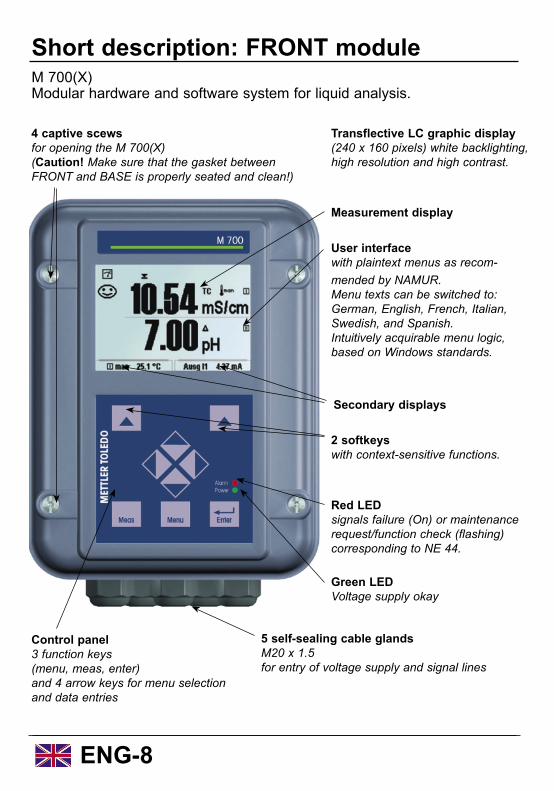
Short description: FRONT moduleM 700(X)Modular hardware and software system for liquid analysis.
Transflective LC graphic display (240 x 160 pixels) white backlighting, high resolution and high contrast.
Red LEDsignals failure (On) or maintenance request/function check (flashing) corresponding to NE 44.
4 captive scewsfor opening the M 700(X)(Caution! Make sure that the gasket between FRONT and BASE is properly seated and clean!)
Green LED Voltage supply okay
5 self-sealing cable glandsM20 x 1.5for entry of voltage supply and signal lines
2 softkeys with context-sensitive functions.
User interface with plaintext menus as recom-mended by NAMUR. Menu texts can be switched to: German, English, French, Italian, Swedish, and Spanish.Intuitively acquirable menu logic, based on Windows standards.
Control panel3 function keys (menu, meas, enter)and 4 arrow keys for menu selectionand data entries
Measurement display
Secondary displays

ENG-9
Measuring
Short description: Menu structureBasic functions: Calibration, maintenance, parameter setting, diagnostics
Calibration Maintenance Parameter setting Diagnostics
Menu groups
1
2
3
1147 2958 1246Operator level
1989Admin. level
Passcode:
Selection offurthermenu items:
Module 1Module 2Module 3
BASE Module 1 Module 2 Module 3
SYSTEM FRONT BASE Module 1 Module 2 Module 3
4
5
Legend:(1) Pressing the menu key accesses menu selection(2) Pressing the meas key returns to measurement(3) Menu groups are selected using the arrow keys(4) Press enter to confirm, enter passcode(5) Further menu items are displayed(6) Selected functions of the Diagnostics menu can be recalled via softkey even when in measuring mode
Message list LogbookDevice descrip-tion
FRONT BASE Module 1 Module 2 Module 3

ENG-10
Short description: FRONT moduleM 700View into the open device (FRONT module)
Terminal plates of “hidden” modules Each module comes with an adhesive label containing the contact assign-ments. This label should be sticked to the inner side of the front (as shown).Then, the terminal assignments remain visible even if further modules are inserted.
Slot for SmartMedia card• Data recording The SmartMedia card expands the measurement recorder capacity to > 50000 records.
• Exchange of parameter sets 5 parameter sets can be stored on the SmartMedia card,
2 of them can be loaded to the M 700(X) and switched by remote control. Parameter sets can be transmitted from one M 700(X) to the other (same hard- and software configuration required).
• Function expansions are possible with additional softwaremodules which are released using transaction numbers (TAN)
• Software updates (also at different devices)
The circumferential sealingguarantees IP 65 protection and allows spray cleaning / disinfection.Caution! Keep clean!
Replacing the front module Pull off power cord and ground wire. To separate the FRONT module from the BASE module, turn the retaining screws of the pivot hinge by 90°.

ENG-11
Short description: BASE module M 700View into the open device (BASE module, 3 function modules installed)
BASE module 2 current outputs (free assignment of process variable) and 4 relay contacts, 2 digital inputs. VariPower broad-range power supply, 20 ... 265 V AC/DC, suitable for all public mains supplies in the world.
Important note concerning SmartMedia cardThe SmartMedia card may be inserted or replaced with the power supply switched on. When closing the device, make sure that the sealing is pro-perly seated and clean.Warning! Do not touch the terminal compartment, there may be dangerous contact voltages!
Module equipment Module identification: Plug & PlayUp to 3 modules can be combined as desired. Several input and communication modules are available.
ENG-12
Inserting the SmartMedia card
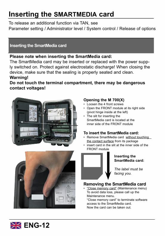
Opening the M 700(X) • Loosen the 4 front screws• Open the FRONT module at its right side (pivot hinge inside at the left) • The slit for inserting the SmartMedia card is located at the inner side of the FRONT module
To insert the SmartMedia card:• Remove SmartMedia card without touching the contact surface from its package• insert card in the slit at the inner side of the FRONT module
Inserting the SMARTMEDIA cardTo release an additional function via TAN, see Parameter setting / Administrator level / System control / Release of options
Please note when inserting the SmartMedia card:The SmartMedia card may be inserted or replaced with the power supp-ly switched on. Protect against electrostatic discharge! When closing the device, make sure that the sealing is properly seated and clean.Warning! Do not touch the terminal compartment, there may be dangerous contact voltages!
Inserting the SmartMedia card:
The label must be facing you.
Removing the SmartMedia card• “Close memory card” (Maintenance menu) To avoid data loss, please call up the Maintenance menu. “Close memory card” to terminate software access to the SmartMedia card. Now the card can be taken out.
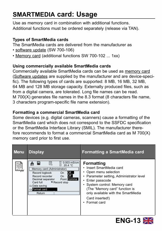
Formatting• Insert SmartMedia card• Open menu selection• Parameter setting, Administrator level• Enter passcode• System control: Memory card (The “Memory card” function is only available with the SmartMedia Card inserted!)• Format card
ENG-13
SMARTMEDIA card: UsageUse as memory card in combination with additional functions.Additional functions must be ordered separately (release via TAN).
Types of SmartMedia cardsThe SmartMedia cards are delivered from the manufacturer as• software update (SW 700-106)
Menu Display Formatting a SmartMedia card
Memory card (Administrator)Record logbook
Return
20.4 °C
Record recorderDecimal separator
Format cardData saving
0.003 mS/cm
Card full
OnOnPoint
Record stop
OffOffComma
• Memory card (additional functions SW 700-102 ... 1xx)
Using commercially available SmartMedia cardsCommercially available SmartMedia cards can be used as memory card (Software updates are supplied by the manufacturer and are device-speci-fic). The following types of cards are supported: 8 MB, 16 MB, 32 MB, 64 MB and 128 MB storage capacity. Externally produced files, such as from a digital camera, are tolerated. Long file names can be read. M 700(X) generates file names in the 8.3 format (8 characters file name, 3 characters program-specific file name extension).
Formatting a commercial SmartMedia cardSome devices (e.g. digital cameras, scanners) cause a formatting of the SmartMedia card which does not correspond to the SSFDC specification or the SmartMedia Interface Library (SMIL). The manufacturer there-fore recommends to format a commercial SmartMedia card as M 700(X) memory card prior to first use.

ENG-14
Insert moduleNote: Be sure to connect the shielding properly!
Insert module
Switch off power supplyOpen the device (loosen the 4 screws at the front)Place module in slot (D-SUB connector)Tighten fastening screws of the moduleOpen ESD shielding cap (if provided)Connect sensor cable. To avoid interferences, the cable shielding must be completely covered by the ESD shielding cap.Close ESD shielding cap (if provided)Close device, tighten screws at the frontSwitch on power supplySet parameters (see module description)
Make sure that the cable glands are tightly closed to protect against humidity.
The terminals of some of the modules are covered by an ESD shield. To connect the sensor cable, just pull it back.
1.2.3.4.5.6.
7.8.9.
10.


Mettler-Toledo GmbHProcess Analytics, Industrie NordCH-8902 Urdorf
Phone: +41 (01) 736 22 11Fax: +41 (01) 736 26 36Internet: http://www.mtpro.com
Subject to technical changes.