lv79 2005 en - siemens suomi · capable circuit-breakers ... lv 70 p price list ... the delivery...
TRANSCRIPT

LV79_2005_en.FH10 Tue Jul 12 11:18:29 2005 Seite 2
&56;3

Related catalogs Contents
Low-VoltageControlgear for IndustryOrder No.: E86060-K1002-A101-A4-7600
LV 10 Contactors and contactor assemblies · Semiconductor controlgear, soft starters, controllers · Circuit-breakers · Overload relays · Load feeders · Switch disconnectors and fuses · SIMIREL time, monitoring, coupling relays and converters · Control and signaling devices · BETA electrical installation technology: Selected products · SIGUARD safety systems · SIDAC-T transformers · SIDAC-S power supplies · ALPHA FIX terminal blocks
Power DistributionProducts and Systems for Power DistributionOrder No.: E86060-K1801-A101-A4-7600
LV 30 BETA protect installation equipment · Communication-capable circuit-breakers · Compact circuit-breakers (MCCB) · Air circuit-breakers (ACB) · SENTRIC switch disconnectors and fuse switch disconnectors · Switch-gear, distribution systems and cabinets
SIVACON 8PSBusbar Trunking Systems CD-K, BD01, BD2 up to 1250 AOrder No.: E86060-K1870-A101-A1-7600
LV 70 Busbar Trunking Units, Overview · System CD-K (25 A - 40 A) · System BD01 (40 A - 160 A) · System BD2 (160 A - 1250 A)
SIVACON 8PSBusbar Trunking Systems CD-K, BD01, BD2 up to 1250 AOrder No.: E86060-P1870-A101-A2-7600
LV 70 P Price ListSystem CD-K (25 A - 40 A) · System BD01 (40 A - 160 A) · System BD2 (160 A - 1250 A)
SIVACON 8PSBusbar Trunking Systems BD2A/BD2C, LDA/LDC from 160 A to 5000 AOrder No.: E86060-T1871-A101-A1-7600
LV 71 T Technical InformationSystem Overview · BD2A/BD2C System · LDA/LDC System · Further Information
SIVACON 8PSBusbar Trunking Systems LXA/LXC over 800 AOrder No.: E86060-T1872-A101-A1-7600
LV 72 T Technical InformationSystem Overview · LXA/LXC System · Further Information
Automation and DrivesThe Offline Mall for A&DOrder No.: E86060-D4001-A110-C3-7600
CA 01 All the products from Automation and Drives including the products from the catalogs listed above.
A&D Mall
Internet:http://www.siemens.com/automation/mall
All the products from Automation and Drives including the products from the catalogs listed above.
Registered trademarks Technical Assistance
All product designations may be registered trademarks or product names of Siemens AG or other supplying companies. Third parties using these trademarks or product names for their own purposes might infringe upon the rights of the trademark owners.Further information about low-voltage switchgear and controlgear is available on the Internet at:http://www.siemens.com/lowvoltage
Tel.: +49 (9 11) 8 95 - 59 00Fax.: +49 (9 11) 8 95 - 59 07
Email: [email protected]
LV79_en_U2.fm Seite 1 Donnerstag, 14. Juli 2005 7:09 07

s
© Siemens AG 2005
SIVACON 8PL Busbar Trunking System
Catalog LV 79 · 2005
Introduction
1
8PL Busbar Trunking System
2
Planning and Projecting for SIVACON 8PL Busbar Trunking System
3
Annex
4

Siemens LV 79 · 20052
Delivery times (DT)
Preferred type
A 2 working days
B 1 week
C 3 weeks
D 6 weeks
X On request
Preferred types are available immediately from stock, i.e. are dispatched within 24 hours.
Normal quantities of the products are usually deliv-ered within the specified time following receipt of your order at our branch.
In exceptional cases, the actual delivery period may differ from that specified.
The delivery periods apply up to the ramp at Siemens AG (products ready for dispatch). The transport times depend on the destination and type of shipping. The standard transport time for Germany is 1 day.
The delivery times specified here represent the situation in October 2004. They are continuously optimized. Up-to-date information can be found at http://www.siemens.com/automation/mall.
Price units (PU)
The price unit defines the number of units, sets or meters to which the specified price and weight apply.
Packaging size (PS)
The packaging size defines the number, e.g. of units, sets or meters, for outer packaging.
Only the quantity defined by the packaging size or a multiple thereof can be ordered!
For multi-unit packaging and recyclable packaging, see Catalog LV 10 · 2004, Annex.
Price group (PG)
Each product is assigned to a price group.
Weight
The defined weight in kg refers to the price unit (PU).
Dimensions
All dimensions in mm.
Explanations

Siemens LV 79 · 2005
1/2 Welcome to Automation and Drives
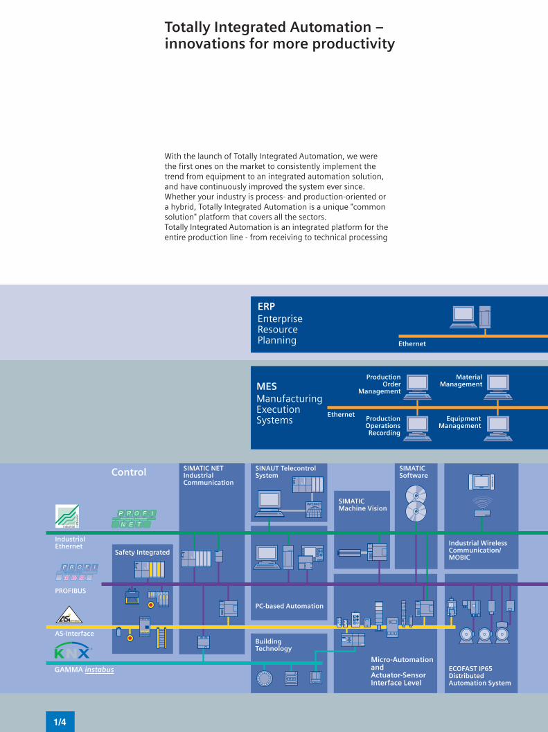
1/4 Totally Integrated Automation –innovations for more productivity
1/6 Totally Integrated Power –energy distribution and management from one source
1/8 Low-voltage switchgear –the basis for progressive solutions
1/10 SIVACON 8PS – Busbar Trunking Systems in Action
1/12 SIVACON 8PL – Busbar Trunking System
Introduction


!
!"
#!$
!
"#
$%&' (
) ) *+
) *
$#,
*(
!, (
*-
.
)'
# (
% && %' ' &
( / *(

*
$-0
* (
+'( * (
1 (
" (
22 *
("!
!! )#0
(3)
' "
! (
!,4!
) (
! .
&
$#,
2
5 (
) (

,
6670.
( -/ (' *
( &
(
*
(
"
+ )
2

#
)*
+ "
"
!$$
!$$
" )
)
-(
#

1/8
Low-voltage switchgear and controlgearThe basis for progressive solutions.
The requirements in the field of low-voltage switchgear and
controlgear are high: Cost-effective solutions are required
that can be easily integrated into switchgear cabinets,
distribution boards or distributed systems and that can
communicate with each other perfectly. Siemens has the
answer to this, with SIRIUS industrial switchgear and low-
voltage power distribution with SIVACON, SENTRON and
SIMARIS.
SIRIUS industrial switchgear
In the SIRIUS product family, you will find everything
that you require for switching, protecting and start-
ing loads. Products for monitoring, controlling, sens-
ing, signalling and power supply round off the spec-
trum of industrial switchgear. Totally Integrated
Automation, Safety Integrated and ECOFAST addi-
tionally permit our product portfolio to be combined
to form optimized systems. All in all, at Siemens you
will find innovative switchgear and control gear with
modern features such as integrated communication
and safety technology that work to your advantage:
The basis for ground-breaking integrated solutions.
SIRIUS modular system SIRIUS Safety Integrated
product family
1/9
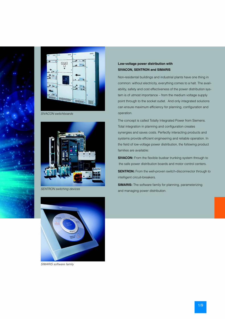
Low-voltage power distribution with
SIVACON, SENTRON and SIMARIS
Non-residental buildings and industrial plants have one thing in
common: without electricity, everything comes to a halt. The avail-
ability, safety and cost effectiveness of the power distribution sys-
tem is of utmost importance – from the medium voltage supply
point through to the socket outlet. And only integrated solutions
can ensure maximum efficiency for planning, configuration and
operation.
The concept is called Totally Integrated Power from Siemens.
Total integration in planning and configuration creates
synergies and saves costs. Perfectly interacting products and
systems provide efficient engineering and reliable operation. In
the field of low-voltage power distribution, the following product
families are available:
SIVACON: From the flexible busbar trunking system through to
the safe power distribution boards and motor control centers.
SENTRON: From the well-proven switch-disconnector through to
intelligent circuit-breakers.
SIMARIS: The software family for planning, parameterizing
and managing power distribution.
SIVACON switchboards
SENTRON switching devices
SIMARIS software family

1/10
The BD 01 system is quick to install and
ideally suited for use in workshops and
trade premises, as here, at a photogra-
pher’s.
The ideal system for production lines
needing a great deal of power is the
LD system up to 5000 A.
In the petrochemical industry, it is the PEC system that provides
reliable and fault-free power supply.
SIVACON 8PS –Busbar Trunking Systems in Action
Busbar trunking systems in the low-voltage range perform
the safe and reliable transmission and distribution of electri-
cal power from transformer via main distribution board and
sub-distribution board right to the load. Siemens busbar
trunking systems are the complete and efficient answer in
this area:
• The CD-K system for 25 A to 40 A• The BD01 system for 40 A to 160 A• The BD2 system for 160 A to 1250 A• The PEC system for 800 A to 6000 A• The LD system for 1100 A to 5000 A• The LX system for 800 A to 6300 A
Alle these systems are ’Type-tested LV switchgear assem-
blies’ (TTA) to IEC/EN 60439-1 and -2. This ensures that
they offer a standard of safety and reliability that meets the
particularly high performance expectations of automated
production and for building services provision.
Performance characteristics:• Clear network structure• Unproblematic retrofitting in the event of load changes• Low operating costs due to uninterrupted serviceability• Simple planning and installation
Room-covering systems for lighting installations and small loads
The CD-K system (up to 40 A) allows you to supply lighting
installations covering the whole expanse of, say, furniture
showrooms, supermarkets or greenhouses with power, and
also provides the means to easily fix them in position.
Due to its pleasing appearance, the equipment is well
suited for use in sales rooms visited by the public.
The power source for loads with no fixed location
The BD01 system is ideally suited for the power supply (up
to 160 A) in workshops and trade premises. The trunking
units are easy and quick to put together. The anti-rotation
feature on the tap-off units makes sure that the units are cor-
rectly fitted and allows for easy retrofitting even while the
production is running. Other benefits: minimum stock hold-
ing and uncomplicated planning due to one standard frame
size for five different current ratings.

1/11
Universal power distribution
The BD2 system (up to 1250 A) can supply power
to medium-size loads in buildings and in all indus-
trial applications. Prefabricated tap-off units fitted
with many differing component combinations
make this equipment universally applicable. Two
standard frame sizes covering all current ratings
simplify stock keeping and planning.
Safe and reliable power transmission in the petrochemical industry
The PEC resin-insulated system, up to 6000 A,
has a high degree of insulation protection and
thus an enormous resistance to external interfer-
ence factors. This ensures safe and reliable trans-
port of power even in rough weather or in highly
dust and dirt and corrosion polluted industrial en-
vironments. Typical applications of this system is
the petrochemical industry, waste incinerators
and power stations.
High system serviceability in production
The louvred LD busbar trunking system, up to
5000 A, is the system for transporting current in
production lines with a large energy requirement,
such as in the automotive industry. A separate PE
busbar ensures that the protective device in such
a system responds reliably even if the current
paths are relatively long. The high short-circuit rat-
ing allows medium-voltage switches to be used
as protective elements for the transmission of
power between transformer and main circuit-
breaker. Tap-off units up to 1250 A available as
standard.
Flexible power distribution in multi-storey buildings
The LX sandwich-style system, up to 6300 A, is
used where large quantities of power need to be
transported, uninfluenced by the mounting posi-
tion of the system.
Conductor configurations with the PE conductor
insulated along its entire length, and a double-
size neutral can ensure the interference-free dis-
tribution of power in places such as radio stations,
computer centres or at internet providers’. The
system is protected up to IP55 as standard, and
tap-off units up to 1250 A available as standard.
Siemens offers modular component cabinets for indication, control and monitoring of the
flow of power through busbar trunking systems. These cabinets are equipped with bus
interfaces, control circuit devices and power meters.
The LX busbar trunking system is the perfect equipment for multi-sto-
rey buildings where large quantities of power need to be transported,
uninfluenced by the mounting position of the system.
1/12
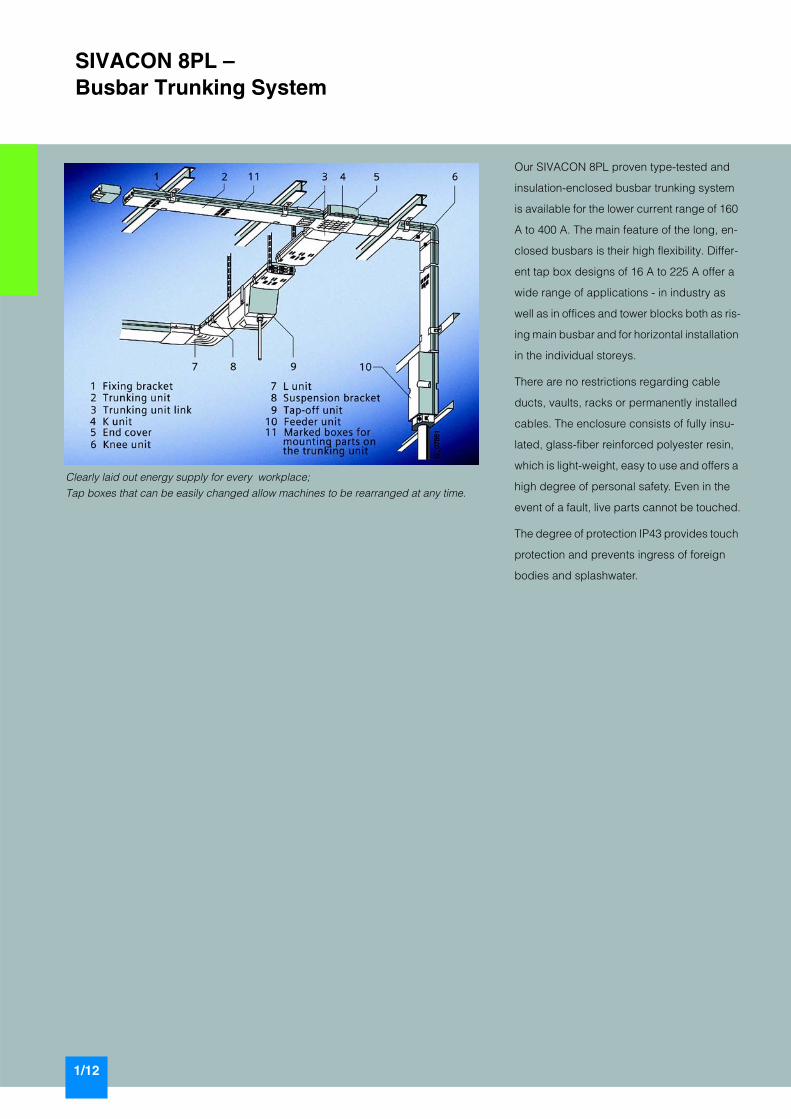
Clearly laid out energy supply for every workplace;
Tap boxes that can be easily changed allow machines to be rearranged at any time.
SIVACON 8PL –Busbar Trunking System
Our SIVACON 8PL proven type-tested and
insulation-enclosed busbar trunking system
is available for the lower current range of 160
A to 400 A. The main feature of the long, en-
closed busbars is their high flexibility. Differ-
ent tap box designs of 16 A to 225 A offer a
wide range of applications - in industry as
well as in offices and tower blocks both as ris-
ing main busbar and for horizontal installation
in the individual storeys.
There are no restrictions regarding cable
ducts, vaults, racks or permanently installed
cables. The enclosure consists of fully insu-
lated, glass-fiber reinforced polyester resin,
which is light-weight, easy to use and offers a
high degree of personal safety. Even in the
event of a fault, live parts cannot be touched.
The degree of protection IP43 provides touch
protection and prevents ingress of foreign
bodies and splashwater.

Siemens LV 79 · 2005
2/2 Introduction2/4 Busway section2/6 Infeed section2/6 Expansion section2/7 Tap boxes2/10 8HP empty section and adapter set2/11 Suspension2/12 Fire barrier2/13 Accessories
SIVACON 8PL –Busway Systems

SIVACON 8PL — Busway System
Introduction
2/2 Siemens LV 79 · 2005
2
Overview
High degree of personnel protection by totally insulated system (safety class 2). Even in case of fault it is impossible to touch live parts.• Type-tested switchgear and controlgear (TTA) in accordance
with EN 60439-2.• High operational reliability for the operating personnel by
means of locked tap-off sections with fuses from 16 A to 225 A, i.e. fuses can only be changed in off-load condition.
• A large variety of combinations by modular system. All tap boxes can be mounted to busway sections of different rated currents. This results in nearly unlimited possibilities for the placement of loads (production machines).
• Adaptation to all structural conditions by using angle (L), cross (K) and knee-bend sections.
• Degree of protection IP43 (IP54 on request),shock hazard protection, protection against foreign solid bod-ies (> 1 mm), spray water up to an angle of 60° to the vertical in accordance with EN 60529.
• Uniform, totally insulated busway system for currents of 160 A, 250 A and 400 A.
• All encapsulation parts are of insulating material (glass-fiber-reinforced polyester resin).
• High strength, low weight.• Low weight facilitates installation and handling.• Flame-retardant, self-extinguishing.• No protective coating required, no maintenance.
Area of application
The 8PL busway system with changeable outgoing feeders was developed for power supply to machines that have to be re-grouped from time to time. This is in accordance with the "Regu-lations for type-tested l.v. switchgear and controlgear assembly (TTA)“ according to EN 60439-2.
The enclosed sections are made of fiber-reinforced polyester. This material offers the following advantages:• Corrosion protection in corrosive atmospheres• Low weight, minimal maintenance, no protective coating
necessary• Protective measure "Safety Class 2" (total insulation).
The 8PL busway system is ideally suited to applications in indus-try and commerce, e.g. in the machine tool, motor, wood pro-cessing, paper processing, textile and food industries and in re-pair shops, laboratories and as vertical conductors in administration buildings.
Design
The tap boxes fit all 3 busway sections for currents of 160 A, 250 A and 400 A. They are electrically and mechanically con-nected to the busway section with an integrated snap-on fixture.
All tap boxes (with the exception of the version without an isolat-ing mechanism) are equipped with disconnector-fuses or DIAZED fuses in the cover so that when the cover is open, all built-in components are de-energized (for replacing the fuse).
In this state, the tap boxes can be taken off or fitted to the busway sections after releasing a mechanical locking mecha-nism; this allows the busway sections to remain live.
The tap boxes are supplied without fuse links and screw caps.
!"#$%&'
()%&'($%&'(*+,

SIVACON 8PL — Busway System
Introduction
2/3Siemens LV 79 · 2005
2
Mounting Length expansion
For lines consisting of more than 10 busway sections in a row, length expansion must be taken into account for the 250 and 400 A systems.In this case, sliding suspensions and expansion sec-tions are to be used.
Shortening busway sections
Busway sections are supplied in lengths of 2.5 m. If shorter sec-tions are required, they can be cut at any point.The 8PL1 080 cover sheet must also be ordered for this purpose.
Technical specifications
For mounting busway sections with:
Fixing bracket
Hanger
Suspension device
Fixing clamp
8PL1 411
8PL1 421
8PL1 422
8PL1 451
!
" # $
%
Data according to EN 60439-2
Rated operational voltage AC VDC V
500600
Rated insulation voltageaccording to DIN VDE 0110 pollution degree 3 AC V
DC V10001200
Rated current
Busbar A 160, 250, 400
Built-in components A 160, 250, 400, up to 225 (continuous current Ith2)
Short-circuit strength of the busbar Icw
at 160 Aat 250 Aat 400 A
24 kA40 kA50 kA
Degree of protection acc. to EN 60529 IP43
Combustion value Details on request
Color of the enclosed parts RAL 7020, slate gray
Protective measures Total insulation (Safety Class 2)
Conductor material Cu
Configuration of the busway section with flat copper rails
Rated current A 160 250 400
3 main conductors per mm 7 x 5 7 x 10 7 x 20
1 center conductor mm 7 x 5 7 x 5 7 x 10
1 protective conductor(for 5-conductor system)
mm 7 x 5 7 x 5 7 x 10
Possible load for higher frequencies
Rated current at 50 Hz A 160 250 400
at 200 Hz A 145 225 320
at 400 Hz A 130 200 250
Ambient temperature
All rated currents apply to an ambient temperature of 35 °C. Current-carrying capacity for other ambienttemperatures in %:
Ambient temperature °C 20 30 35 40 50
Rated current load
160 A in % 112 106 100 97 90
250 A in % 112 106 100 97 90
400 A in % 112 106 100 97 90

SIVACON 8PL — Busway System
Busway section
2/4 Siemens LV 79 · 2005
2
Selection and ordering data
1) Busway section connection is required.
for rated current DT Order No. Price per PU
PU (item, set, meter)
PS* PG Weightper PU
A item kg2.5 m busway section 1)
5-conductor system, 6 outgoing feeders are possible
160 C 8PL2 010 1 1 145 6.800
250 C 8PL4 01 1 1 145 9.600
400 C 8PL6 01 1 1 145 16.000
5-conductor system, 6 outgoing feeders are possible
400 C 8PL5 01 1 1 145 15.000
L section 1)
160 C 8PL2 110 1 1 145 0.800
250 C 8PL4 11 1 1 145 1.000
400 C 8PL6 11 1 1 145 1.700
K section 1)
160 C 8PL2 130 1 1 145 1.400
250 C 8PL4 13 1 1 145 1.900
400 C 8PL6 13 1 1 145 3.600
Knee-bend section 1)
160 C 8PL2 150 1 1 145 0.700
250 C 8PL4 15 1 1 145 0.700
400 C 8PL6 15 1 1 145 0.800
Busway section connection
160 C 8PL2 060 1 1 145 1.100
250 C 8PL4 06 1 1 145 1.100
400 (4-conductor and 5-conductor system) C 8PL6 06 1 1 145 1.100
AccessoriesEnd cover
160, 250, 400 C 8PL1 24 1 1 145 0.100
* You can order this quantity or a multiple thereof.

SIVACON 8PL — Busway System
Busway section
2/5Siemens LV 79 · 2005
2
Dimensional drawings
Busway sections L section K section
8PL2 010, 8PL4 01, 8PL6 01
8PL2 110, 8PL4 11, 8PL6 11
8PL2 130, 8PL4 13, 8PL6 13
Knee-bend section
8PL2 150, 8PL4 15, 8PL6 15
Infeed section
8PL2 210, 8PL4 21
8PL6 21
Expansion section Infeed section
Rated current
Cable gland Maximum conductor cross-section
8PL4 171, 8PL6 171
NYY NYCWY
A mm2 mm2
8PL2 210 160 cable entry 3 x 120/70 4 x 120/70
8PL4 21 250 for cablesØ 14 - 65 mm
3 x 120/70 or4 x 150
4 x 120/70
8PL6 21 400 cable clamp 3 x 185/95 or2 x 4 x 95
1 x 4 x 150/70
I2_07675
125
325389
152
for M 8
125
325389
195
I2_07677
225
40
for M 8
I2_07676279307
220
232
21
18.5
Busway section

SIVACON 8PL — Busway System
Infeed section
2/6 Siemens LV 79 · 2005
2
Selection and ordering data
Overview
Length expansion
For lines consisting of more than 10 busway sections in a row, length expansion must be taken into account for the 250 and400 A systems.
In this case, sliding suspensions and expansion sections are to be used.
Selection and ordering data
for rated current DT Order No. Price per PU
PU (item, set, meter)
PS* PG Weightper PU
A item kgfor horizontal installation
160 C 8PL2 210 1 1 145 2.000
250 C 8PL4 21 1 1 145 2.200
400 C 8PL6 21 1 1 145 2.900
for vertical installation(including fixing rail),use 8HP1 520 cable entry plate for feeding in the cable.
160 C 8PL2 215 1 1 145 6.000
250 C 8PL4 215 1 1 145 6.200
400 C 8PL6 215 1 1 145 6.400
Expansion section
for rated current DT Order No. Price per PU
PU (item, set, meter)
PS* PG Weightper PU
A item kgfor horizontal installation
250 C 8PL4 171 1 1 145 6.300
400 C 8PL6 171 1 1 145 6.800
for vertical installation(including fixing rail)
250 C 8PL4 175 1 1 145 8.100
400 C 8PL6 175 1 1 145 8.500
* You can order this quantity or a multiple thereof.

SIVACON 8PL — Busway System
Tap boxes
2/7Siemens LV 79 · 2005
2
Selection and ordering data
No. of con-duc-tors
DT Order No. Price per PU
PU (item, set, meter)
PS* PG Weightper PU
item kgDIAZED fuse bases
25 A with 3 DIAZED fuse bases DII 5 C 8PL2 311 1 1 145 1.400
4 C 8PL1 311 1 1 145 1.300
25 A with 3 DIAZED fuse bases DII (larger terminal compartment)
5 C 8PL2 31 1 1 145 2.300
4 C 8PL1 31 1 1 145 2.200
with SCHUKO socket outlets
1 x 16 A DII,2 Schuko socket outlets without isolating mechanism
5 C 8PL2 33 1 1 145 0.800
4 C 8PL1 33 1 1 145 0.700
3 x 25 A,3 SCHUKO socket outlets with hinged cover, 16 A, 230 V, splash-proof
5 C 8PL2 312-2 1 1 145 2.600
with CEE socket outlets
3 x 25 A DII,2 CEE socket outlets 16 A, 230 V, 6 h, 5-pole
5 C 8PL2 335 1 1 145 2.300
4 C 8PL1 335 1 1 145 2.200
3 x 25 A,2 CEE socket outlets 16 A, 230 V, 6 h, 5-pole
5 C 8PL2 312-1 1 1 145 2.600
3 x 25 A,2 CEE socket outlets, sloping, 16 A, 400 V, 6 h, 5-pole
5 C 8PL2 313-1 1 1 145 2.600
with SCHUKO socket outlets and CEE socket outlets
3 x 25 A,2 SCHUKO socket outlets, 16 A, 230 V,1 CEE socket outlet, 16 A, 400 V, 6 h, 5-pole
5 C 8PL2 313-2 1 1 145 2.600
with RCCB
3 x 25 A,2 SCHUKO socket outlets, 16 A, 230 V,NFI, 25 A, 30 mA, 4-pole
5 C 8PL2 312-3 1 1 145 2.700
3 x 25 A,2 CEE socket outlets, 16 A, 400 V, 6 h,NFI, 25 A, 30 mA, 4-pole
5 C 8PL2 313-3 1 1 145 2.700
with miniature circuit-breaker
3 x 25 A,1 MCB, 16 A, 230 V, 3-pole
5 C 8PL2 312-4 1 1 145 2.700
* You can order this quantity or a multiple thereof.

SIVACON 8PL — Busway System
Tap boxes
2/8 Siemens LV 79 · 2005
2
LV HRC fuse links100 A for 3 LV HRC fuse links, Size 00 5 C 8PL2 34 1 1 145 2.200
4 C 8PL1 34 1 1 145 2.100
225 A for 3 LV HRC fuse links, Size 1 5 C 8PL2 351 1 1 145 6.800
4 C 8PL1 351 1 1 145 6.500
with CEE socket outlets
3 x NH002 CEE socket outlets, 32 A, 5-pole
5 C 8PL2 336 1 1 145 2.300
4 C 8PL1 336 1 1 145 2.200
3 x NH00,1 CEE socket outlets, 16 A, 400 V, 6 h, 5-pole
5 C 8PL2 341-1 1 1 145 2.700
3 x NH00,1 CEE socket outlets, 32 A, 400 V, 6 h, 5-pole
C 8PL2 343-1 1 1 145 2.700
3 x NH00,1 CEE socket outlet, 63 A, 400 V, 6 h, 5-pole
5 C 8PL2 345-1 1 1 145 2.700
with RCCB
3 x NH00,NFI, 25 A, 30 mA, 4-pole
5 C 8PL2 342-6 1 1 145 2.700
3 x NH00,NFI, 40 A, 30 mA, 4-pole
5 C 8PL2 344-6 1 1 145 2.700
3 x NH00,NFI, 63 A, 30 mA, 4-pole
5 C 8PL2 345-6 1 1 145 2.800
3 x NH00,NFI, 40 A, 30 mA, 4-pole,2 CEE socket outlets, 32 A, 400 V, 6 h, 5-pole
5 C 8PL2 343-3 1 1 145 2.800
No. of con-duc-tors
DT Order No. Price per PU
PU (item, set, meter)
PS* PG Weightper PU
item kg
* You can order this quantity or a multiple thereof.

SIVACON 8PL — Busway System
Tap boxes
2/9Siemens LV 79 · 2005
2
Dimensional drawings
LV HRC fuse linkswith RCCB3 x NH00,NFI, 40 A, 0.5 A, 4-pole
5 C 8PL2 344-5 1 1 145 2.800
3 x NH00,NFI, 63 A, 0.5 A, 4-pole
5 C 8PL2 345-5 1 1 145 2.800
with miniature circuit-breaker3 x NH00,1 MCB, 16 A, 400 V, 3-pole
5 C 8PL2 341-7 1 1 145 2.800
3 x NH00,2 MCB, 16 A, 1-pole,2 SCHUKO socket outlets, 16 A, 230 V
5 C 8PL2 341-4 1 1 145 2.800
No. of con-duc-tors
DT Order No. Price per PU
PU (item, set, meter)
PS* PG Weightper PU
item kg
8PL1 311, 8PL2 3118PL1 31, 8PL2 31, 8PL1 333, 8PL2 333, 8PL1 335, 8PL2 335, 8PL1 336, 8PL2 336, 8PL1 34, 8PL2 34
8PL1 351, 8PL2 351 8PL1 33, 8PL2 33
* You can order this quantity or a multiple thereof.
SIVACON 8PL — Busway System
8HP empty section and adapter set
2/10 Siemens LV 79 · 2005
2
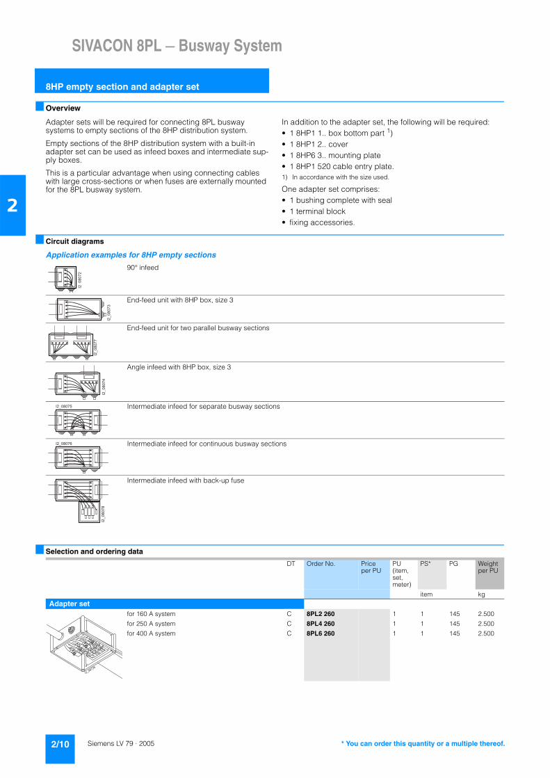
Overview
Adapter sets will be required for connecting 8PL busway systems to empty sections of the 8HP distribution system.
Empty sections of the 8HP distribution system with a built-in adapter set can be used as infeed boxes and intermediate sup-ply boxes.
This is a particular advantage when using connecting cables with large cross-sections or when fuses are externally mounted for the 8PL busway system.
In addition to the adapter set, the following will be required:• 1 8HP1 1.. box bottom part 1)• 1 8HP1 2.. cover• 1 8HP6 3.. mounting plate• 1 8HP1 520 cable entry plate.1) In accordance with the size used.
One adapter set comprises:• 1 bushing complete with seal• 1 terminal block• fixing accessories.
Circuit diagrams
Application examples for 8HP empty sections
Selection and ordering data
90° infeed
End-feed unit with 8HP box, size 3
End-feed unit for two parallel busway sections
Angle infeed with 8HP box, size 3
Intermediate infeed for separate busway sections
Intermediate infeed for continuous busway sections
Intermediate infeed with back-up fuse
DT Order No. Price per PU
PU (item, set, meter)
PS* PG Weightper PU
item kg
Adapter setfor 160 A system C 8PL2 260 1 1 145 2.500
for 250 A system C 8PL4 260 1 1 145 2.500
for 400 A system C 8PL6 260 1 1 145 2.500
* You can order this quantity or a multiple thereof.

SIVACON 8PL — Busway System
Suspension
2/11Siemens LV 79 · 2005
2
Overview
Suitable for all types of busway sections. Every busway section must be fixed with at least two suspensions.
The following components are available:• clip• hanger• suspension.
Selection and ordering data
Dimensional drawings
DT Order No. Price per PU
PU (item, set, meter)
PS* PG Weightper PU
kg
Clip
comprising two fixing clamps C 8PL1 411 1 1 set 145 0.050
Hanger
comprising two fixing clamps C 8PL1 421 1 1 set 145 0.180
Suspension device
sliding ability for large length expansion over allcomponents
C 8PL1 422 1 1 set 145 0.220
Clip Hanger
8PL1 411
8PL1 421
Sliding suspension Fixing clamp
8PL1 422
8PL1 451
98
I2_0
7666
35158
30
Pendelum attachmentwith steel strip
* You can order this quantity or a multiple thereof.
SIVACON 8PL — Busway System
Fire barrier
2/12 Siemens LV 79 · 2005
2
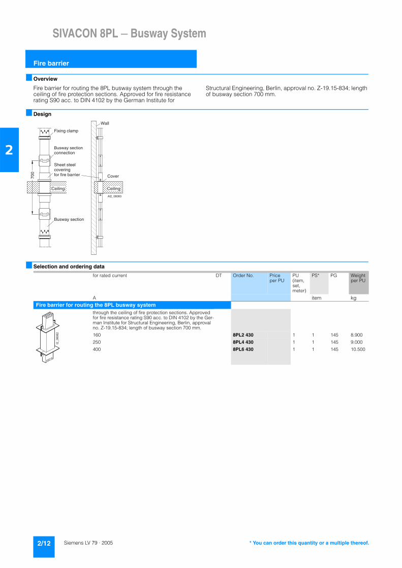
Overview
Fire barrier for routing the 8PL busway system through theceiling of fire protection sections. Approved for fire resistance rating S90 acc. to DIN 4102 by the German Institute for
Structural Engineering, Berlin, approval no. Z-19.15-834; length of busway section 700 mm.
Design
Selection and ordering data
I2_08083
700
Fixing clamp
Busway sectionconnection
Sheet steelcoveringfor fire barrier
Busway section
CeilingCeiling
Cover
Wall
A
for rated current DT Order No. Price per PU
PU (item, set, meter)
PS* PG Weightper PU
A item kgFire barrier for routing the 8PL busway system
through the ceiling of fire protection sections. Approved for fire resistance rating S90 acc. to DIN 4102 by the Ger-man Institute for Structural Engineering, Berlin, approval no. Z-19.15-834; length of busway section 700 mm.
160 8PL2 430 1 1 145 8.900
250 8PL4 430 1 1 145 9.000
400 8PL6 430 1 1 145 10.500
* You can order this quantity or a multiple thereof.

SIVACON 8PL — Busway System
Accessories
2/13Siemens LV 79 · 2005
2
Selection and ordering data
1) At least one fixing clamp is required for each busway section.
DT Order No. Price per PU
PU (item, set, meter)
PS* PG Weightper PU
item kgfor horizontal and vertical installation
Cover sheetwith instructions for cutting to fit and connecting cut ends of busway sections
C 8PL1 080 1 1 set 145 0.020
Cover for sealingunused outgoing feeder points. The cover can only be removed by destroying it.
C 8PL1 400 1 1 145 0.022
for horizontal installationMounting luminaires1 unit/pendant
C 8PL1 46 1 1 145 0.180
Wiring clipsfor holding wires, up to 4 wires from 9 mm to 19 mm Ø C 8PL1 471 1 1 145 0.180
Adapter set for the 8HP distribution systemfor use of empty 8HP section as supply box comprising one bushing with seal, fixing accessories and one terminal block
for 160 A system C 8PL2 260 1 1 145 2.500
for 250 A system C 8PL4 260 1 1 145 2.500
for 400 A system C 8PL6 260 1 1 145 2.500
for vertical installationFixing clamp 1)(including bolts and nuts)for fixing on the C-section rail
8PL1 451 1 1 set 145 0.175
* You can order this quantity or a multiple thereof.

SIVACON 8PL — Busway System
Notes
2/14 Siemens LV 79 · 2005
2
7

Siemens LV 79 · 2005
3/2 Number of conductors3/2 Extension of existing systems3/2 Ambient temperature3/2 Possible load for higher
frequencies3/3 Feed-in3/3 Bus plugs3/3 Lengthwise expansion3/4 Short-circuit and overload
protection3/7 Voltage drop3/8 Hangers3/9 Lighting arrangements3/9 Fire barrier3/11 Busway run3/12 Shortening busway sections
Planning and Projecting for SIVACON 8PLBusway Systems

Planning and Projecting for Busway Systems
Number of conductors
3/2 Siemens LV 79 · 2005
3
Design
Only 5-conductor designs are supplied for the 8PL busway sec-tions for 160 A and 250 A. Incoming 4-conductor cables are di-vided into the 5-conductor system in the feed-in sections. 8PL busway sections for 400 A rated current are supplied in 4-con-ductor and 5-conductor designs.
The 5-conductor design must be used for locations exposed to fire hazards.
According to VDE 0100/5.73, an additional fifth conductor must be installed for conductor cross-sections under 10 mm2. For this reason, all bus plugs for 4-conductor busway sections, up to and including 100 A rated current, have a separate PE and N ca-ble lug.
Under certain conditions they can also be used, among others, in timber, paper, and textile processing plants.
If the corresponding rooms are exposed to fire hazards, the 5-conductor design must also be used for the 8PL busway sys-tem independent of the current strength "from the last distribu-tion outside the rooms exposed to fire hazards" (VDE 0100/5.73 § 50).
Configuration of the busway section with flat copper
Overview
In future, existing systems with 4-conductor 160 A or 250 A busway sections must be extended exclusively with 5-conductor busway sections. In this case, the fifth busbar is not connected.
If the 8PL1 31 bus plug is used for a 4-conductor system, the un-used contact must be sawn off flush with the box.
Technical specifications
All rated currents apply to an ambient temperature of 35 °C. Current-carrying capacity for other ambient temperatures in %
Technical specifications
Rated current 3 main conductors per
1 center conductor
1 protective conductor (for 5-conductor system)
A mm mm mm
160 7 x 5 7 x 5 7 x 5
250 7 x 10 7 x 5 7 x 5
400 7 x 20 7 x 10 7 x 10
Extension of existing systems
Ambient temperature
Ambient temperature
Load in % of the rated current
°C 160 A 250 A 400 A
20 112 112 112
30 106 106 106
35 100 100 100
40 97 97 97
50 90 90 90
Possible load for higher frequencies
Rated current at 50 Hz 200 Hz 400 Hz
A A A
160 145 130
250 225 200
400 320 250

Planning and Projecting for Busway Systems
Feed-in
3/3Siemens LV 79 · 2005
3
Function
Installation of K sections permits intermediate infeeds over the length of a busway run so that the power of a line can be subse-quently extended at any time.
Function
The fuses in the bus plugs are used to provide short-circuit pro-tection for the output lead to the load. Overload protection is not required if the individual loads (e.g. motors) within the machine control are already protected in accordance with VDE 0113. In all other cases, it must be checked if the fuse to be installed in the bus plug is to be used for short-circuit protection only or also for overload protection.
Overview
For lines with more than 10 busway sections (corresponds to 25 m), the lengthwise expansion for the 250 A and 400 A system at rated load must be considered. Flexible suspension devices and expansion fittings are available for this purpose.
Feed-in from one side
Feed-in from two sides
Feed-in in the center
Bus plugs
Lengthwise expansion
Planning and Projecting for Busway Systems
Short-circuit and overload protection
3/4 Siemens LV 79 · 2005
3
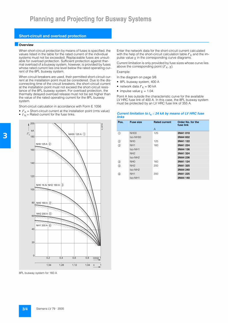
Overview
When short-circuit protection by means of fuses is specified, the values listed in the table for the rated current of the individual systems must not be exceeded. Replaceable fuses are unsuit-able for overload protection. Sufficient protection against ther-mal overload of a busway system, however, is provided by fuses whose rated current lies one level below the rated operating cur-rent of the 8PL busway system.
When circuit breakers are used, their permitted short-circuit cur-rent at the installation point must be considered. Due to the dis-connecting time of the circuit breakers, the short-circuit current at the installation point must not exceed the short-circuit resis-tance of the 8PL busway system. For overload protection, the thermally delayed overload release must not be set higher than the value of the rated operating current for the 8PL buswaysystem.
Short-circuit calculation in accordance with Form E 1056• I“K = Short-circuit current at the installation point (rms value)• I N = Rated current for the fuse links.
8PL busway system for 160 A
Enter the network data for the short-circuit current calculated with the help of the short-circuit calculation table I“K and the im-pulse value χ in the corresponding curve diagrams.
Current limitation is only provided by fuse sizes whose curve lies above the corresponding point (I“K, χ).
Example:
In the diagram on page 3/6• 8PL busway system, 400 A• network data I“K = 90 kA• impulse value χ = 1.04.
Point A lies outside the characteristic curve for the available LV HRC fuse link of 400 A. In this case, the 8PL busway system must be protected by an LV HRC fuse link of 355 A.
Current limitation to Is ≤ 24 kA by means of LV HRC fuse links
!
!
!
"#
! !
!
$%#
$%#
$% #&$% #
$% #!
$%#
$%#
'"
Pos. Fuse size Rated current Order No. for the fuse link
A$ NH00 125 3NA1 010
Iso-NH00 3NA4 832
% NH0 125 3NA1 122
& NH1 160 3NA1 224
Iso-NH1 3NA4 136
NH2 3NA1 324
Iso-NH2 3NA4 236
( NH0 160 3NA1 124
) NH2 200 3NA1 325
Iso-NH2 3NA4 240
* NH1 200 3NA1 225
Iso-NH1 3NA4 140

Planning and Projecting for Busway Systems
Short-circuit and overload protection
3/5Siemens LV 79 · 2005
3
8PL busway system for 250 A
Current limitation to Is ≤ 40 kA by means of LV HRC fuse links
!
!
!
"#
! !
$%#
$%#
$%#!
$%#
$%!#$%!#&
'"
Pos. Fuse size Rated curent Order No. for the fuse link
A$ NH1 224 3NA1 226
Iso-NH1 3NA4 142
NH2 3NA1 326
Iso-NH2 3NA4 242
% NH2 250 3NA1 327
Iso-NH2 3NA4 244
& NH1 250 3NA1 227
Iso-NH1 3NA4 144
( NH3 300 3NA1 428
Iso-NH3 3NA4 350
) NH2 300 3NA1 328
Iso-NH2 3NA4 250

Planning and Projecting for Busway Systems
Short-circuit and overload protection
3/6 Siemens LV 79 · 2005
3
8PL busway system for 400 A
Current limitation to Is ≤ 50 kA by means of LV HRC fuse links
!
!
!
"#
! !
$%#&$%#
$%!#
$%!#
$%!#!
'"
#
Pos. Fuse size Rated current Order No. for the fuse link
A$ NH2 355 3NA1 331
Iso-NH2 3NA4 254
NH3 3NA1 431
Iso-NH3 3NA4 354
% NH3 400 3NA1 432
Iso-NH3 3NA4 360
& NH2 400 3NA1 332
Iso-NH2 3NA4 260
( NH3 425 3NA1 433

Planning and Projecting for Busway Systems
Voltage drop
3/7Siemens LV 79 · 2005
3
Caracteristic curves
The voltage drop ∆U for three-phase current is
∆U = √3 x a x I x L x (R p.f. + X sinϕ)
Explanation:
Factor a depends on current distribution. It is assumed that the current changes relatively continuously over the length of the busway.
Voltage drop for 8PL busway system for 160 A for three-phase current in mV/m
Voltage drop for 8PL busway system for 250 A for three-phase current in mV/m
Voltage drop for 8PL busway system for 400 A for three-phase current in mV/m
∆U Voltage drop in V
I Operating current in A
L Total length of busway in m
a Current distribution factor (see table)
(for 8PL busway system for)
R 0.51 10-3 Ω/m0.25 10-3 Ω/m0.12 10-3 Ω/m
160 A250 A400 A
X 0.16 10-3 Ω/m0.16 10-3 Ω/m0.16 10-3 Ω/m
160 A250 A400 A
Current distribution Voltage drop Factor
1/2
1/4
1/8
(
(
!
(
!
!
)&
)&
)&
&
!
!
)&
)&
)&
&
!
!
)&
)&
)&
&

Planning and Projecting for Busway Systems
Hangers
3/8 Siemens LV 79 · 2005
3
DesignWith the help of the galvanically zinc-coated bichromatized 8PL1 411 fixing brackets the busway sections are fixed directly to aligned cross-arms, smooth ceilings, and walls etc. If length-wise expansions are to be expected, the 8PL1 422 flexiblehangers must be used.
For room heights over 2.5 m, 8PL1 421 fixing brackets must be used as well as slotted steel strips and steel cables etc. pro-vided by the customer.
Each busway section must be fixed on at least two points.
Only the sections which are marked on the busway section must be used for fixing the busway section so as to leave space for the bus plugs.
The feed-in sections must be fixed to a fixed cross-arm using two M8 screws.
!
" # $
%
*** +**,+
-,
.,
/0*/
Hanger spacing 1.25 m. Rigid mount with slotted steel strips; feed-in at the end of the line.
-,
.,
/0*/
Hanger spacing 2.5 m; guy wire used in-between.
Planning and Projecting for Busway Systems
Lighting arrangements
3/9Siemens LV 79 · 2005
3
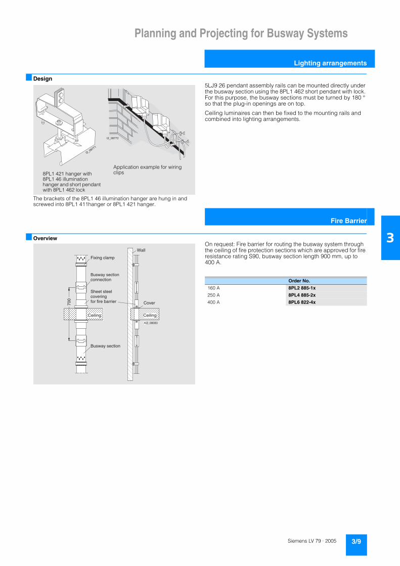
Design
The brackets of the 8PL1 46 illumination hanger are hung in and screwed into 8PL1 411hanger or 8PL1 421 hanger.
5LJ9 26 pendant assembly rails can be mounted directly under the busway section using the 8PL1 462 short pendant with lock. For this purpose, the busway sections must be turned by 180 ° so that the plug-in openings are on top.
Ceiling luminaires can then be fixed to the mounting rails and combined into lighting arrangements.
OverviewOn request: Fire barrier for routing the busway system through the ceiling of fire protection sections which are approved for fire resistance rating S90, busway section length 900 mm, up to 400 A.
8PL1 421 hanger with8PL1 46 illuminationhanger and short pendant with 8PL1 462 lock
Application example for wiring clips
Fire Barrier
I2_08083
700
Fixing clamp
Busway sectionconnection
Sheet steelcoveringfor fire barrier
Busway section
CeilingCeiling
Cover
Wall
A
Order No.
160 A 8PL2 885-1x
250 A 8PL4 885-2x
400 A 8PL6 822-4x

Planning and Projecting for Busway Systems
Fire barrier
3/10 Siemens LV 79 · 2005
3
Application
Vertical installation
Example for power supply
Example for the power supply of a 24-floor administration building with busway system 8PL for 400 A used as a rising main busway.
Horizontal installation
Application example for a machine plant
Clearly structured power supply for each workplace. Changeable feeders permit the machines to be converted at any time.
NYY 2x3x95/50 mm2
I2_0
5795
c
24
23
22
21
20
19
18
17
16
15
14
13
12
11
10
9
8
7
6
5
4
3
2
1
Buswaysection
Expansionsection
Outgoing feeders to individualstoreys
Busway system 400 A,split into three sections
1**/2*3
45 +,55
1**/2*3
165+*
-,
-,
45 +,55
1/*5.65**
/ 0**5
75 8,5/5

Planning and Projecting for Busway Systems
Busway run
3/11Siemens LV 79 · 2005
3
Overview
Vertical busway run
The 8PL busway system for vertical installation can be used as a rising busway in high-rise building. These are in accordance with the "Regulations for type-tested l.v. switchgear and con-trolgear assembly (TTA)“ according to EN 60439-2.
Fire protection
Due to fire protection regulations, the openings in the ceiling for the corresponding fire protection sections must be sealed with fire barrier.
Benefits
Using busways as main rising busways rather than using "clas-sical" installations with a number of cables has the advantage of providing a better overview over the conductors and requires less time for installation. If the amount of power required on dif-ferent floors changes over time, this can be covered without hav-ing to install additional equipment.
The low weight of the molded-plastic enclosure makes installa-tion of vertical busway sections significantly easier.
Design
It is easy to seal the 8PL busway system, if necessary: All bus plugs are fitted with capstan screws. There must be a bore hole in the handle shell for this purpose.Sealing becomes unnecessary if the 8PL1 400 covers are latched into unused bus plugs. This prevents electricity theft. Covers cannot be removed without breaking them.
Function
The busway sections are installed in the riser ducts with the help of armature mounting rails which must be supplied by the cus-tomer. When mounting the busway sections, care must be taken that the slides of the plug-in points can always be opened from below. The busway sections are fixed to the mounting rails with 8PL1 451 fixing clamps. At least one fixing clamp is required for each busway section.
The expansion fittings support the weight of the busway sections on top in the same way as the feed-in sections.

Planning and Projecting for Busway Systems
Shortening busway sections
3/12 Siemens LV 79 · 2005
3
OverviewThe busway sections are only supplied in lengths of 2.5 m. If shorter busway sections are required, they can be shortened anywhere in area x.
K sections can be installed anywhere over the length of a busway section including the beginning and end of the busway section.
Cut busway section ends must only be connected with uncut busway sections, L or K sections. In addition, the 8PL1 080 cover foil is required.
Application
Application examples with shortened busway sections
99
9
(
99
9
(
(
I2_0
7663
a
Cross section
A
End cover
Connection ofbusway sections
Infeed sectionCenter infeed sectionwith cross section
I2_0
7664
a
150
mm
150 mm
A
Change of direction
Intermediatesection
Angle section
Knee section
Verticalinfeed
Least possible changeof direction
InfeedsectionWithout intermediate
section 290 mmWith intermediatesection 440 mm
Intermediate-section

Planning and Projecting for Busway Systems
Shortening busway sections
3/13Siemens LV 79 · 2005
3
Design
Shortening 8PL busway sectionsShortening
The sections can be short-ened anywhere in this area*). The cut section must not be < 150 mm.
Installation
Shortened busway sections must only be connected to un-shortened busway sections.
This requires the following equipment: 8PL... busway section connection8PL1 080 cover sheet.
1. Concatenation
2. Inserting the chamber piece
3. Covering the interface
&
&
' (
) $ $ # *
%
I2_07672a
Connecting terminal
A
When concatenating busway sections, ensure that the phase is in the correct position !
I2_07673a
Chamber piece Cover sheet
A
Insert chamber piece, then wrap the interface in a sheet
I2_07674a
Case
A
Cover interface with the shell coversfor the busway section connection

Planning and Projecting for Busway Systems
Notes
3/14 Siemens LV 79 · 2005
3
7

Siemens LV 79 · 2005
4/2 Siemens contacts4/3 A&D online services4/4 Customer support4/5 Subject index4/6 Order number index4/7 Conditions of sale and delivery,
export regulations
Annex

Annex
Siemens Contacts
4/2 Siemens LV 79 · 2005
4
At
http://www.siemens.com/automation/partner
you can find details of Siemens contact partners worldwideresponsible for particular technologies.
You can obtain in most cases a contact partner for• Technical Support,• Spare parts/repairs,• Service,• Training,• Sales or• Consultation/engineering.
You start by selecting a• Country,• Product or• Sector.
By further specifying the remaining criteria you will find exactly the right contact partner with his/her respective expertise.

AnnexService & Support
Information and Orderingin the Internet and on CD-ROM
4/3Siemens LV 79 · 2005
4
A&D in the WWWA detailed knowledge of the range of products and services available is essential when planning and configuring automation systems. It goes without saying that this information must always be fully up-to-date.
The Siemens Automation and Drives Group (A&D) has therefore built up a comprehensive range of information in the World Wide Web, which offers quick and easy access to all data required.
Under the address
http://www.siemens.com/automation
you will find everything you need to know about products, sys-tems and services.
Product Selection Using the Interactive CatalogDetailed information together with convenient interactive func-tions: The interactive catalog CA 01 covers more than 80,000 products and thus provides a full summary of the Siemens Automation and Drives product base.
Here you will find everything that you need to solve tasks in the fields of automation, switchgear, installation and drives. All information is linked into a user interface which is easy to work with and intuitive.
After selecting the product of your choice you can order at the press of a button, by fax or by online link.
Information on the interactive catalog CA 01 can be found in theInternet under
http://www.siemens.com/automation/ca01
or on CD-ROM or DVD:
Easy Shopping with the A&D Mall The A&D Mall is the virtual department store of Siemens AG in the Internet. Here you have access to a huge range of products presented in electronic catalogs in an informative and attractive way.
Data transfer via EDIFACT allows the whole procedure fromselection through ordering to tracking of the order to be carried out online via the Internet.
Numerous functions are available to support you.
For example, powerful search functions make it easy to find the required products, which can be immediately checked for avail-ability. Customer-specific discounts and preparation of quotes can be carried out online as well as order tracking and tracing.
Please visit the A&D Mall on the Internet under:
http://www.siemens.com/automation/mall

AnnexCustomer Support
Our Services for Every Phase of Your Project
4/4 Siemens LV 79 · 2005
4
.I
In the face of harsh competition you need optimum conditions to keep ahead all the time: A strong starting position. A sophisticated strategy and team for the necessary support - in every phase. Service & Support from Siemens provides this support with a complete range of different services for automation and drives.
In every phase: from planning and startup to maintenance and upgrading.
Our specialists know when and where to act to keep the produc-tivity and cost-effectiveness of your system running in top form.
Online SupportThe comprehensive information system available round theclock via Internet ranging from Product Support and Service & Support services to Support Tools in the Shop.
http://www.siemens.com/automation/service&support
Technical SupportCompetent consulting in techni-cal questions covering a wide range of customer-oriented ser-vices for all our products and systems.
Tel.: +49 (0)180 50 50 222Fax: +49 (0)180 50 50 223http://www.siemens.com/automation/support-request
Technical ConsultingSupport in the planning and de-signing of your project from de-tailed actual-state analysis, target definition and consulting on product and system ques-tions right to the creation of the automation solution. 1)
Configuration and Software EngineeringSupport in configuring and de-veloping with customer-oriented services from actual configura-tion to implementation of the au-tomation project. 1)
Service On SiteWith Service On Site we offer services for startup and mainte-nance, essential for ensuring system availability.
In Germany 0180 50 50 444 1)
Repairs and Spare PartsIn the operating phase of a ma-chine or automation system we provide a comprehensive repair and spare parts service ensur-ing the highest degree of oper-ating safety and reliability.
In Germany 0180 50 50 446 1)
Optimization and UpgradingTo enhance productivity and save costs in your project we of-fer high-quality services in opti-mization and upgrading. 1)
1) For country-specific telephone numbers go to our Internet site at: http://www.siemens.com/automation/service&support

Annex
Subject index
4/5Siemens LV 79 · 2005
4
Page Page Page
AAccessories 2/13
for horizontal and vertical installation 2/13Adapter set 2/10Adapter set for the 8HP distribution system 2/13Ambient temperature 3/2Application examples
for empty sections 2/10
BBus plugs 3/3Busway run
vertical 3/11Busway section 2/4Busway section connection 2/4
CCover for sealing 2/13Cover sheet 2/13
DDIAZED fuse base 2/7
EEmpty section and adapter set 2/10End cover 2/4Expansion section 2/6
for horizontal installation 2/6for vertical installation 2/6
Extension of existing systems 3/2
FFeed-In 3/3Fire barrier 2/12, 3/9Fire protection 3/11Fixing clamp 2/13
HHangers 3/8
IInfeed section 2/6
for horizontal installation 2/6for vertical installation 2/6
Installationhorizontal 3/10vertical 3/10
Introduction 2/2
KK section 2/4Knee-bend section 2/4
LL section 2/4Length expansion 2/3, 2/6Lengthwise expansion 3/3Lighting arrangements 3/9LV HRC fuse link 2/8
MMounting 2/3Mounting luminaires 2/13
NNumber of conductors 3/2
PPossible load for higher frequencies 3/2
SShort-circuit and overload protection 3/4Shortening busway sections 2/3, 3/12Suspension 2/11
fixing bracket 2/11
TTap boxes 2/7...2/9
VVoltage drop 3/7
WWiring clips 2/13
Annex
Order number index
4/6 Siemens LV 79 · 2005
Order No. Page Order No. Page Order No. Page
4
8PL18PL1 080 2/138PL1 24 2/48PL1 31 2/78PL1 311 2/78PL1 33 2/78PL1 335 2/78PL1 336 2/88PL1 34 2/88PL1 351 2/88PL1 400 2/138PL1 411 2/118PL1 421 2/118PL1 422 2/118PL1 451 2/138PL1 46 2/138PL1 471 2/13
8PL28PL2 010 2/48PL2 060 2/48PL2 110 2/48PL2 130 2/48PL2 150 2/48PL2 210 2/68PL2 215 2/68PL2 260 2/10, 2/138PL2 31 2/78PL2 311 2/78PL2 312-1 2/78PL2 312-2 2/78PL2 312-3 2/78PL2 312-4 2/78PL2 313-1 2/78PL2 313-2 2/78PL2 313-3 2/78PL2 33 2/78PL2 335 2/78PL2 336 2/88PL2 34 2/88PL2 341-1 2/88PL2 341-4 2/98PL2 341-7 2/98PL2 342-6 2/88PL2 343-1 2/88PL2 343-3 2/88PL2 344-5 2/98PL2 344-6 2/88PL2 345-1 2/88PL2 345-5 2/98PL2 345-6 2/88PL2 351 2/88PL2 430 2/12
8PL48PL4 01 2/48PL4 06 2/48PL4 11 2/48PL4 13 2/48PL4 15 2/48PL4 171 2/68PL4 175 2/68PL4 21 2/68PL4 215 2/68PL4 260 2/10, 2/138PL4 430 2/12
8PL58PL5 01 2/4
8PL68PL6 01 2/48PL6 06 2/48PL6 11 2/48PL6 13 2/48PL6 15 2/48PL6 171 2/68PL6 175 2/68PL6 21 2/68PL6 215 2/68PL6 260 2/10, 2/138PL6 430 2/12

Annex
Conditions of sale and delivery
4/7Siemens LV 79 · 2005
4
Terms and Conditions of Sale and Delivery
By using this catalog you can acquire hardware and software products described therein from the Siemens AG subject to the following terms. Please note! The scope, the quality and the con-ditions for supplies and services, including software products, by any Siemens entity having a registered office outside of Ger-many, shall be subject exclusively to the General Terms and Conditions of the respective Siemens entity.
For customers with a seat or registered office in the Federal Republic of GermanyThe „General Terms of Payment“ as well as the „General Condi-tions for the Supply of Products and Services of the Electrical and Electronics Industry“ shall apply.For software products, the „General License Conditions for Soft-ware Products for Automation and Drives for Customers with a Seat or registered Office in Germany“ shall apply.
For customers with a seat or registered office outside of GermanyThe „General Terms of Payment“ as well as the „General Condi-tions for Supplies of Siemens, Automation and Drives for Cus-tomers with a Seat or registered Office outside of Germany“ shall apply.For software products, the „General License Conditions for Soft-ware Products for Automation and Drives for Customers with a Seat or registered Office outside of Germany“ shall apply.
GeneralThe prices are in € (Euro) ex works, exclusive packaging.The sales tax (value added tax) is not included in the prices. It shall be debited separately at the respective rate according to the applicable legal regulations.In addition to the prices of products which include silver, plump, aluminum and/or copper, surcharges may be calculated if the respective limits of the notes are exceeded. The respective note (e.g. source: German newspaper „Handesblatt“ in category „deutsche Edelmetalle“ and „Metallverarbeiter“) for silver („ver-arbeitetes Silber“), plump („Blei in Kabeln“), aluminum („Alumin-ium in Kabeln“) and copper („Elektrolytkupfer“, „DEL-Notiz“) re-spectively, of the day the order or rather the on call order is received, is decisive for the calculation of the surcharges.Surcharges of copper shall be calculated for Drives at a note („DEL-Notiz“) above EUR 225,00 / 100 Kg and for chokes / trans-formers above EUR 150,00 / 100 kg.Surcharges shall be charged based on the quantities of the ma-terials which are contained in the relevant products.Prices are subject to change without prior notice. We will debit the prices valid at the time of delivery. The dimensions are in mm. Illustrations are not binding.Insofar as there are no remarks on the corresponding pages, - especially with regard to data, dimensions and weights given - these are subject to change without prior notice.
Comprehensive Terms and Conditions of Sale and Delivery are available free of charge from your local Siemens business office under the following Order Nos.:• 6ZB5310-0KR30-0BA0
(for customers based in the Federal Republic of Germany)• 6ZB5310-0KS53-0BA0
(for customers based outside of theFederal Republic of Germany)
or download them from the Internet:http://www.siemens.com/automation/mall (Germany: A&D Mall Online-Help System)
Export regulations
The products listed in this catalog / price list may be subject to European / German and/or US export regulations.Therefore, any export requiring a license is subject to approval by the competent authorities.According to current provisions, the following export regulations must be observed with respect to the products featured in this catalog / price list:
Even without a label or with an “AL: N“ or “ECCN: N“, authoriza-tion may be required due to the final destination and purpose for which the goods are to be used.The deciding factors are the AL or ECCN export authorization indicated on order confirmations, delivery notes and invoices.Errors excepted and subject to change without prior notice.
A&D/VuL/En 17.03.05
AL Number of the German Export List.Products marked other than “N“ require an export license.In the case of software products, the export des-ignations of the relevant data medium must also be generally adhered to.Goods labeled with an “AL not equal to N“ are subject to a European or German export authori-zation when being exported out of the EU.
ECCN Export Control Classification Number.Products marked other than “N“ are subject to a reexport license to specific countries.In the case of software products, the exportdesignations of the relevant data medium must also be generally adhered to.Goods labeled with an “ECCN not equal to N“ are subject to a US re-export authorization.

Annex
Notes
4/8 Siemens LV 79 · 2005
4
Siemens AGAutomation and DrivesLow-Voltage Controls and DistributionPostfach 48 4890327 NÜRNBERGGERMANY
Order No.E86060-K1879-A101-A1-7600En/503112Printed in Germany

LV79_2005_en.FH10 Tue Jul 12 11:18:29 2005 Seite 1
!"#$%#&'%(('%)#*
++, -#+'../0"000".1234
56+7
58 8838833 88+8 8 39 983 + 38:+