luminescent spectral splitting: efficient spatial division of solar spectrum at low concentration
TRANSCRIPT

Solar Energy Materials & Solar Cells 95 (2011) 1741–1755
Contents lists available at ScienceDirect
Solar Energy Materials & Solar Cells
0927-02
doi:10.1
n Corr
E-m
journal homepage: www.elsevier.com/locate/solmat
Luminescent spectral splitting: Efficient spatial division of solar spectrumat low concentration
Brent Fisher n, John Biddle
Institute for Defense Analyses, 4850 Mark Center Drive, Alexandria, VA 22311, USA
a r t i c l e i n f o
Article history:
Received 30 November 2010
Received in revised form
18 January 2011
Accepted 28 January 2011Available online 23 February 2011
Keywords:
Optics
Luminescence
Nanocrystals
Concentrating photovoltaics
Multijunction
48/$ - see front matter & 2011 Elsevier B.V. A
016/j.solmat.2011.01.043
esponding author. Tel.:+1 703 845 6768; fax
ail addresses: [email protected] (B. Fisher), jbid
a b s t r a c t
The purpose of this study was to investigate the potential performance of a novel concept for dividing
solar radiation into spectral components that separately illuminate photovoltaic (PV) cells of different
band gaps using an optical design that (1) is simple, easily manufactured, and extensible to many
spectral channels and (2) does not achieve high geometric concentration factors. The concept that we
explore leverages the approach of stacked luminescent solar concentrators (LSCs) for dividing the solar
spectrum using fluorophores that are tuned to different spectral bands. However, whereas multicolor
LSCs must perform two functions using the same optical component—spectral division and
concentration—we consider the performance of a similar design when only one demand—spectral
division—is placed on it. We find that the optical quantum and power efficiencies can be quite high
(QE490%, PE480%) compared to what one might intuitively expect. When we couple the light output
to a simple detailed balance model of a solar cell using experimental performance parameters we find
that solar-to-electric conversion could exceed 30% with four junctions, using existing PV materials.
While this does not exceed what can be achieved by HCPV designs on multijunction epitaxially grown
stacks, the concept presented here has the major advantage of being easily extensible to an arbitrarily
large number of spectral channels. Because of this extensibility, the number of junctions in the system
is limited only by the availability of PV cells with appropriate band gaps, so significantly higher system
efficiencies should be accessible without major revision to the basic design presented here.
& 2011 Elsevier B.V. All rights reserved.
1. Introduction
Optical division of the solar spectrum, known as ‘‘spectralsplitting,’’ is an old concept that enables designing a multijunc-tion PV module with a number of potential advantages: (1) cur-rent matching all the subcells is not required; (2) each subcellmaterial may be fabricated on a different substrate, so there is noneed for lattice matching or thick metamorphic layers, and eachsubcell may be independently optimized; (3) a larger number ofjunctions may be accessible. Concepts for spectral splitting havegenerally always considered spectral splitting in combinationwith optical concentration, but combining these functions into asingle design can lead to problems. Designs based on dichroics arefundamentally challenged because concentration leads to largedistributions of input angles, but the performance of dichroics forspectral splitting degrades when the range of angles it mustaccommodate becomes large. Stacks of luminescent solar con-centrators (LSCs) are another option for spectral division and
ll rights reserved.
:+1 703 578 2877.
[email protected] (J. Biddle).
concentration, but their optical efficiency has been severelyconstrained by reabsorption within the devices.
In this paper we consider a concept that aims to split the solarspectrum with maximum optical efficiency, but using a simpledesign that is easy to manufacture and is easily extensible to anarbitrary number of subcells. Optical concentration is used in thisdesign, but high concentration is not a requirement. Dispensingwith high concentration as the singular focus permits us toexplore a design space of what we call luminescent spectrumsplitters (LSS), which are essentially a variation on LSCs thatfocuses first on high efficiency and good spectral splitting, withconcentration a secondary concern. Based on a home-built ray-tracing simulation that uses experimental data to model theperformance of luminescent materials, optical quantum efficien-cies of 95% are achievable with optical power efficiencies of 75%(after the Stokes shift of the emission). An extension of this modelcouples the optical output to PV materials reported in literatureand suggests that module efficiencies of 30–35% and higher couldbe realized by these designs. A very clear tradeoff between netoptical concentration and efficiency is explored, and a few designvariations that could overcome this tradeoff are discussed.Because we find that high-efficiency operation is currently limitedto designs with fairly low concentration (o10� ), this approach

B. Fisher, J. Biddle / Solar Energy Materials & Solar Cells 95 (2011) 1741–17551742
may not be economically viable if the PV materials are high cost(e.g., III–V materials). However, this work demonstrates that if afairly low-cost PV were available at a wide variety of band gapvalues, the LSS concept could provide a highly efficient, manu-facturable, and easily extensible approach to a stitching the PVmaterials together in a multijunction module.
2. Materials and methods
It is well known that solar-to-electric conversion efficiency canbe greatly enhanced by using more than one band gap in amultijunction photovoltaic system. The benefit is derived bybreaking the tradeoff between high current and voltage that isthe basis of the Shockley–Quiesser limit. The great majority ofmultijunction PV devices in both research and production arebased on multiple junctions stacked in optical series, usually byepitaxial growth of one material on another. An alternativeapproach to the multijunction stack is to employ optics thatseparate portions of the incident solar spectrum and direct themto different spatial locations. This concept has been around formany decades, and a thorough review is given by Imenes andMills [1]. Some examples of efforts to optically split the solarspectrum include the RAINBOW multijunction design fromNASA [2,3], holographic splitting [4], and more recently aDARPA-funded CPV project [5,6]. There are at least two potentialadvantages associated with optical separation of the solarspectrum:
1.
The individual PV cells do not need to be epitaxially grown ontop of one another, so the material choices and growthconditions are less restricted. In principle each junction couldbe grown on a separate substrate. This would of coursemultiply substrate costs, but it would also reduce growth timeand precursor usage often associated with graded layers inmetamorphic devices or many of the other intermediate layers(e.g., tunnel junctions) required in complex multijunctions.2.
Each individual junction may be separately contacted withoutthe need for transparent, buried contacts so there is no currentmatching requirement across the PV devices. Among otherthings such a device would be less susceptible to diurnal andseasonal variation of the illumination spectrum—a problemthat limits the practical efficiency gains of series connectedmultijunction devices when the number of junctions becomeslarge [7].A variety of optical designs have been proposed and built forthe purpose of spatially dividing the solar (or any broadband)spectrum. Most of these employ either dispersion in an opticalmaterial (e.g., a prism) or a wavelength-dependent reflectivesurfaces such as dichroic mirrors. There are at least three aspectsof designs based on dichroic mirrors that are not ideal. First, thewavelength at which a dichroic mirror switches from reflective totransmissive depends on the angle of incidence of the propagatinglight. This means that if the light field incident on the dichroic iscomposed of rays incident over a wide distribution of angles (asfound at the output of a primary concentrating optic), then eachray will encounter a dichroic with a different cutoff wavelength. Aweighted average of the dichroics reflectance spectrum over allthese angles can yield spectral division that is not very sharp. Asecond challenge associated with optical designs based ondichroics is their ‘‘extensibility.’’ A design might be found thatperforms well for separation of the spectrum into two compo-nents, but adding third, fourth, or fifth channel would usuallyrequire a complete redesign. The third challenge associated withoptical designs based on dichroics and assembled from many
individual pieces is economic cost. High-performance dichroicscan easily cost many hundred dollars per square meter, and themanufacturing of assemblies with large part counts drivesup cost.
Stacked LSCs offer an alternative to dichroics for spectrumsplitting, but these generally have not yielded high opticalefficiencies. The major challenge associated with LSCs is reab-sorption of the wave-guided photons before they are able to reachthe targeted PV cells. The degree to which reabsorption limits theperformance of an LSC is directly connected to its geometricdimensions [8] (aspect ratio) which is, by definition, its concen-tration factor. In short, it is the demand for both concentrationand spectrum splitting functionality that makes high-efficiencyLSCs difficult to realize. The concept we present here dispenseswith large net concentration as a requirement to explore howhigh the optical and system efficiency of a luminescent spectrumsplitter (LSS) can be with concentration of secondary importancein the design requirements.
3. Calculation
Fig. 1 is an illustration of the particular instantiation of ourconcept. The first component is an unspecified non-imagingconcentrator optic such as a compound parabolic concentrator.The second component is simply a cylindrical light guide throughwhich light propagated by total internal reflection (TIR). Thefunction of splitting the spectrum is fulfilled in the light guideby doping sequential segments of it with a tunable fluorophorethat has a very high luminescent quantum yield, in this casesemiconductor nanocrystals. The technology for embedding semi-conductor nanocrystals inside polymer matrices or inorganicmatrices with little loss of luminescent quantum yield (QY) hasbeen previously established by various routes ranging frompolymerization [9–12] to sol–gel composites [13–15], so themanufacture of such optical components is certainly possible.The principle of operation is evident from the figure: broadband,plane-wave light is incident on the primary optic and concen-trated before entering the second component where each wave-length propagates until it encounters a segment that is dopedwith nanocrystals whose band gap is lower in energy than thegiven wavelength. Photons that are absorbed by the fluorophoresare then re-emitted isotropically. Some photons will be capturedwithin the waveguide, propagating back out the entrance aper-ture of the device—these are lost. Others may propagate furtherdown the device to be absorbed by the next color segment, whilethe rest will not meet the TIR condition and will exit thewaveguide laterally. It is along these color segments where PVmaterials would be placed to collect the narrowband radiationthat is emitted from each color segment of this luminescentspectrum splitter (LSS). For our investigation we primarily con-sidered a cylindrical design with rotational symmetry about the z-
axis, but rectilinear or other designs are also possible. Moredetailed investigations could compare performance of thesecategories.
3.1. Parameters
Before undertaking a detailed analysis of this concept, weidentified the relevant design parameters and investigated thetradeoffs required between these. These parameters, illustratedin Fig. 1, are the following:
n0 refractive index of cladding on LSSn1 refractive index of LSS interiorni refractive index at input to LSS and exit of primary optic

Fig. 1. Diagram of luminescent spectral splitting concept (not to scale). The gap between primary concentrator and the LSS is inflated so that angle definitions can be
illustrated.
B. Fisher, J. Biddle / Solar Energy Materials & Solar Cells 95 (2011) 1741–1755 1743
Lseg/R unitless ratio between length of color segment andradius of rotationally symmetric LSS
Ptrans probability of transmission for a photon traveling par-allel to the z-axis when it encounters a color segmentand has a wavelength equal to the band-edge absorptionpeak of the nanocrystal dopants
Lspace/R unitless ratio of the length of spacing between colorsegments and the radius of the rotationally symmetricLSS
yin acceptance half angle of primary concentrator. Forcalculation of maximum primary concentration weassume that yin¼1.5 deg
These design parameters can be used to immediately computea few key quantities that describe a design’s performance. The TIRangle yTIR is the angle of incidence inside the waveguide at whichTIR kicks in—the larger the TIR angle, the more likely anisotropically emitted photon will exit the waveguide.
yTIR ¼ sin�1ðn0=n1Þ ð1Þ
The acceptance angle of the LSS, aLSS, on the other hand is themaximum angle for which TIR will be supported within the lightguide. Photons that are incident at angles greater than aLSS do notpropagate through the LSS.
aLSS ¼ sin�1ffiffiffiffiffiffiffiffiffiffiffiffiffiffin2
1�n20
q=ni
� �ð2Þ
If we demand that the range of angles at the output of theprimary optic is contained within the acceptance angle of the LSS,the maximum concentration permitted by 100% conservation ofoptical etendue is given by (see Ref. [16])
C1 max ¼nout sinðyoutÞ
nin sinðyinÞ
� �2
¼ni sinðaLSSÞ
1� sinðy0Þ
� �2
¼n2
1�n20
sin2ðy0Þ
!ð3Þ
Finally, the degree to which the LSS de-concentrates inputradiation is just the ratio between the area of the cylinder wall thatthe PV material must cover to capture any photons emitted from agiven color segment and the area of the input aperture of the LSS
Dmax ¼2pRðLsegþLspaceÞ
pR2¼
2Lseg
R1þ
2RtanyTIR
Lseg
� �ð4Þ
where the first factor 2Lseg/R is the de-concentration resulting fromcovering the entire length of a color segment with PV, and the
second factor, (1+2R tan yTIR/Lseg), is an approximation of how muchextra coverage is needed to collect emitted photons with thesteepest angle for which a meridional ray still does not meet TIRand can escape. In this expression the de-concentration D is giventhe subscript ‘‘max’’ because we measure the de-concentrationaccording to the largest area over which photons might be spreadaccording to not meeting the TIR condition. Also note that weassume Lspace, the spacing between color segments, is set such that itis twice the maximum z distance a photon could traverse while stillnot meeting the TIR condition and exiting: Lspace¼R� tan yTIR.
So the net concentration of the system is computed as
CNET ¼n2
1�n20
sin2ðy0Þ
!�2Lseg
R1þ
2RtanyTIR
Lseg
� �� �ð5Þ
Without any consideration of dopant fluorophores we canimmediately recognize a fundamental tradeoff of this concept.As the difference between the cladding and core refractive indicesdecreases, the TIR angle increases and the fraction of isotropicallyemitted photons that can escape likewise increases. At the sametime, however, the LSS acceptance angle aLSS decreases, causingthe maximum concentration permitted by the primary optic todecrease. There is a tradeoff between the fraction of isotropicallyemitted photons that are collected (exit through side) and the netconcentration of the system. This is illustrated in Fig. 2.
Another expected limitation on the concentration levels thatwould be practical in this device is a consequence of heating thatoccurs when the luminescent materials in the LSS absorb solarillumination and re-radiate at longer wavelengths. Any differencebetween the energy of the photon absorbed and the photon thatis re-emitted is converted to heat. The minimum amount ofheating is the energy of the Stokes shift between the lowestenergy photons that can be absorbed and the energy of thephotons emitted.
If PV material and cell costs are a major component of the coststructure when designing an LSS, then the best design will strike acompromise between permitting high concentration while col-lecting reasonably high fractions of isotropic emission. Fig. 2shows, though, that the more one tries to drive up the concentra-tion, the more collection efficiency will drop and the higherinternal temperatures will be driven. On the other hand, if PVmaterial costs are not overwhelming, the optimal design maydrive photon collection fraction (i.e., QE) up while sacrificing net

Fig. 2. Expected limitations on concentration for the LSS concept. Left: the fraction of isotropic luminescence that can exit the LSS through the side (as calculated
in Appendix B) is plotted against the CNET (given in Eq. (5)) by varying the cladding index n0. Each line corresponds to a different value of Lseg/R. Right: estimates of the
steady-state temperature in a disk as a function of concentration if 850 W/m2 is incident and 80% of the incident light is converted to heat. Different lines indicate different
Lseg/R aspect ratios of the ‘‘disks.’’ Dashed lines assume a surface heat-transfer coefficient out the sides of the disk (excluding the top/bottom of disk) of h¼20 W/m2/K.
Solid lines assume h¼150 W/m2/K.
B. Fisher, J. Biddle / Solar Energy Materials & Solar Cells 95 (2011) 1741–17551744
optical concentration. It is in this regime of low net concentrationwhere our investigation of LSS will focus.
3.2. Experimental methods
To investigate the performance of this optical system in moredetail than is permitted by simple analytical expressions (with noapproximations), we constructed a Monte Carlo ray-tracing modelthat simulates the propagation of incident photons through theLSS. In this model, rays are introduced to the inside of the LSS atuniformly random locations across the input aperture of the LSS.The initial propagation direction of each photon is randomlydrawn from uniform distributions in xy-plane azimuth and froma user-defined distribution for the angle theta between thedirection of propagation and the z-axis. For most runs the inputtheta distribution was uniform between 0 and aLSS and zerootherwise.1 At each propagation step of the ray-tracing one ofthree possible events was possible: (1) absorption by a chromo-phore, (2) intersection with the sidewall of the LSS, or (3) inter-section with the boundary between adjacent segments. For eachof these three outcomes a distance is computed at each step: thedistance to the sidewall, the distance until the z-plane of inter-section between two segments is reached, and a randomly drawnabsorption distance based on Beers law using an extinctioncoefficient obtained from the absorption spectra for the fluor-ophore found in the present segment. Whichever distance isshortest determines which event occurs at each propagation step.If case (3) occurs nothing is changed, and the photon continues onthe same trajectory in the next step. If case (2) occurs—sidewallintersection—then the angle of incidence and associated Fresnelreflection coefficient are computed. A random number is drawnand compared with this reflection coefficient to determinewhether or not the photon exits the LSS. If the photon is absorbed(case 1) then a random number is drawn and compared to thequantum yield of the chromophore to determine whether or not anew photon is re-emitted. If one is re-emitted its new propaga-tion direction is obtained by random draw from uniform dis-tributions of zenith and azimuth angles, and its new wavelengthis obtained by random draw from a distribution set by thefluorophore’s emission spectrum, modified such that the emission
1 We also simulated input angle distributions that were (1) a delta function at
yincidence¼0 (i.e., a uniform plane wave in the z-direction) and (2) a realistic
distribution obtained from a parabolic concentrator. The performance was quite
insensitive to the initial distribution of input angles.
wavelength is not permitted to be smaller than the wavelength ofthe photon before it was absorbed. This simple approach topropagating photons through the LSS permits most of the relevantphysics to be captured. Iteration over N photons allows theperformance of the LSS to be simulated. For batch runs toinvestigate parameter dependencies we usually used N¼20,000,and for results presented here we used N¼100,000 photons tosimulate the performance.
For our study we sought to simulate a system that is realis-tically feasible using present technology. We chose glass orpolymer materials doped with semiconductor nanocrystals toserve as the luminescent segments of the LSS. We selected arefractive index for the LSS of n1¼1.62, corresponding to opticalglass, but the cladding index, n0, was a varied parameter. We didnot adjust n1 to account for the presence of (higher index)nanocrystals because the loading fractions were relatively small.To emulate actual nanocrystal optical behavior we used absorp-tion and emission spectra obtained from literature reports onactual materials. One advantage of using semiconductor nano-crystals in the LSS is the tunability of their band gap based onnanocrystal size. This property along with the use of just threedifferent nanocrystal materials (CdSe, InAs, and PbSe) wouldallow almost any band gap to be obtained between 450 and2000 nm. We could not obtain separate unique spectra for everypossible band gap value. Therefore, we obtained absorption andemission spectra from six separate reports, and translated thenearest spectrum to match whatever band gap value was desiredin each segment of the LSS in a simulation run.2 The six absorp-tion spectra are shown in Fig. 3. The output of each Monte Carloray-tracing run was a data structure that contained the propaga-tion history and fate of each test ray. From these data we derivedall the results given in the next section.
4. Results
Our simulation experiments had two main goals. First wesought to identify the design parameters that yielded the bestoptical efficiency for a given low optical concentration (from 2�to 10� ). We then sought to quantify the sensitivity of the opticalperformance to these design parameters.
2 For example, if the spectrum for nanocrystals with a band-edge absorption
at 1600 nm were desired, the green spectrum in Fig. 3 would be selected and
translated such that its first absorption peak matched 1600 nm.

Fig. 3. Absorption spectra used for model runs. Two of the spectra are from CdSe nanocrystals of different sizes [1,2], one is from InAs nanocrystals [3], and the other three
are from PbSe nanocrystals of various sizes [4–6].
Fig. 4. Two representations of the wavelength spectrum of the LSS optical output are given as a function of z. On the left a color map indicates number of photons emitted
at each wavelength l and position z out of the N¼105 input. On the right the spectrum of all photons output from four separate regions of the LSS (indicated by dashed
lines on the left-hand side) plus the back end of the LSS are shown. The inset to the left figure shows the absorption and emission spectra for each color segment of this
design. The design parameters yielding this result are Lseg/R¼5.0 and n0¼1.60, n1¼1.62, Ptrans¼0.01, Lspace/R¼5.04.
3 From Beer’s law a simple derivation yields: l=Lðr,z,f,yÞ ¼ �1= logð1�preabsorbtionÞ
where /yS indicates an average over r, z is the position from which a photon
is emitted and f, y is the angular direction of its emission. L(r,z,f,y) is the distance
to the boundary of the color segment, and QUOTE is the inverse of the extinc-
tion coefficient (i.e., the average distance a photon propagates before being
absorbed).
B. Fisher, J. Biddle / Solar Energy Materials & Solar Cells 95 (2011) 1741–1755 1745
4.1. Quantum efficiencies attainable
To explore efficiency limits, we empirically optimized theoptical efficiency by running batches of simulations in whichwe varied Lseg/R between 0.1 and 10, n0 between 1.4 and 1.55, andPtrans between 0.0001 and 0.02, with other parameter values heldconstant (n1¼1.62, QY¼1.0). In general when Lseg/R increased andwhen n0 increased, the optical efficiency increased (but concen-tration decreased). A number of parameter combinations wereidentified for which the optical quantum efficiency (QE, i.e.,number of photons out divided by number input) exceeded 90%,and we present the results of one typical high QE example in thissection.
When we set Lseg/R¼5.0 and n0¼1.60, we obtained QE¼94%and PE¼75% for the LSS (QE¼80% and PE¼70% when only sidewalls are counted). Fig. 4 shows how the output spectrum variesalong the length of the LSS when we assume an input concentra-tion (C1) of 94� . In this design, the spacing length is large enough(Lspace/Lseg¼5.0) that the emission spectra from adjacent color
segments do not overlap significantly. Furthermore, these datashow that relatively narrowband emission exits each segment ofthe LSS. Based on the results of this run, the probability ofreabsorption inside the same segment was 0.35, which gives aphoton better than even odds of escaping without reabsorption.With some conversion3 this reabsorption probability means thaton average an emitted photon travels 2.3 times as far as theaverage distance to a boundary of the color segment before beingreabsorbed [2.3¼–1/ln(1–0.35)]. For comparison, standard LSCdesigns have a ratio of average transmission length (l) to diskradius (r) in the range from l/r¼0.05 to 0.1. A good discussion ofhow l/r relates to reabsorption and overall efficiency of LSCs is

Fig. 5. On the left-hand side differential quantum and power efficiency along the z-axis of the LSS are given for the design described in Fig. 4. By sorting each differential
contribution, the cumulative distribution of QE or PE can be computed as a function of cumulative length Z that is covered by PV. The total Z area that is covered is
inversely proportional to net concentration of the system. The right-hand plot shows the tradeoff between QE or PE and net concentration for this particular design.
Vertical red dashed lines in the plot indicate nominal concentration values: CNET,2¼C1/D1 where D1¼2Lseg/R is computed on the basis of covering only the length of each
color segment and no more; CNET,1¼C1/D2 where D2¼2Lseg/R*(1+2 tan yTIR) is based on covering not only the length of each color segment, but also the maximum Z
distance that a ray that meets the TIR condition can traverse before meeting the wall after departing a color segment. (For interpretation of the references to color in this
figure legend, the reader is referred to the web version of this article.)
B. Fisher, J. Biddle / Solar Energy Materials & Solar Cells 95 (2011) 1741–17551746
given by Olson [8]. Because the QY was assumed to be 100% inthese optimization simulations, the reabsorption did not have toosevere an impact on the QE of the LSS. The most important sourceof QE loss by far was fluorescence that traveled in the reversedirection back out the front (5%), which we term, ‘‘return losses.’’The severity of this loss mode does depend on the how manycycles of re-emission a ray undergoes, but for this design it wasnot too severe.
4.2. Tradeoff: quantum efficiency vs. Concentration and temperature
Based on the design parameters for this run we compute twoillustrative net concentration values, CNET,1 and CNET,2. The firstcorresponds to a case where PV would cover all locations alongthe length of the LSS where a photon is emitted, and is computedby Eq. (5), yielding 2� . The second estimate of net concentrationassumes that only the length of each color segment is covered byPV and none of the spacing between color segments has PVcoverage, so instead of Eq. (4), the de-concentration factor of theLSS is D2¼2lseg/R. The net concentration ratio based on thisassumption is 9.4� . In Fig. 5 we show the distribution of QEand PE along the z-axis of the LSS and then, based on those data,how these efficiencies vary with net concentration when thefraction of PV coverage on the LSS sidewall is varied. We find thatalthough covering only the color segment portions of the LSS (andnone of the space between) can yield a higher net concentrationratio (9.4� ), one pays a penalty (�10%) in QE as the curve beginsto roll off. All LSS designs exhibited a tradeoff between QE and netgeometric concentration (PV savings) like that shown in Fig. 5(b).We can generalize that a QE within about 1–2% of the CNET,1 isobtained for a net concentration value around half-way betweenCNET,1 and CNET,2.
The previous results gave a reasonable estimate for howefficient a basic LSS design could be realized if net concentrationvalues of less than 10� are required. We also explored how muchthe efficiency is reduced if much higher net concentration valuesare required, for example, 100�–500� . For such a case largervalues of aLSS are required, so n0 must be reduced, which results ina lower fraction of isotropic emission escaping the sidewalls ofthe LSS and therefore lower QE. More important, though, istemperature. Because of the de-concentration factor (greater than2�–5� in general) required to keep the average path length forexiting photons /lS lower than the average absorption length l,net concentrations of 100�–500� require primary concentra-tions of 500�–1500� . At these primary concentrations, the
radiative load into the LSS may exceed 85 W/cm2 and if QY ismuch less than unity (e.g., say, 20%), heating loads can be over10 kW/cm3, leading to temperatures well above 100 1C. At suchtemperatures severe mechanical degradation would be likely, aswell as the degradation of luminescent quantum yield that sets inat even moderate temperatures (e.g., 70–100 1C). For thesereasons results of designs for medium and high concentrationare not reported here.
4.3. Solar-to-electric conversion estimates
We calculated the solar-to-electric conversion efficiency thatwould be achievable if PV cells with band gaps matched to theseoptical spectra (e.g., AlInGaP, InGaAs, Si, and Ge) were coupled toeach of our LSS designs. We used reported VOCs and EQE spectra tocompute the current generation and found that a system based onthe results in Figs. 4 and 5 would yield a solar-to-electricconversion efficiency in the neighborhood of 30%, depending onexactly what band gap values are chosen and how high the VOC
actually is for each cell. The individual efficiencies of each channelwere 58%, 56%, 30%, and 11% (high to low band gap). When weallowed EQE to go to unity for each cell, the system efficiencyincreased to around 35%, with individual channel efficiencies of63%, 61%, 39%, and 15% (high to low band gap). For the colorsegments coupled to PV cells with band gaps above 1 eV, theindividual channel efficiency results are quite consistent with thereported performance of PV cells (so-called photovoltaic powerconverters), which are designed to convert narrowband laserillumination to electricity [17–19]. In such devices light-to-electricity conversion is in the 50–60% efficiency range. Theindividual channel efficiencies for lower band gaps in our modelare lower because of higher dark currents. Appendix A gives amore detailed explanation of our estimates for solar-to-electricefficiency.
4.4. LSS dependence on luminescence quantum-yield and other
design parameters
Because the assumption of unity QY in the foregoing resultsrepresents by far the most optimistic of all parameter assump-tions, it is important to know how sensitive the performance is tothe QY of individual fluorophores. Fig. 6 shows that the overallefficiency of the LSS varies almost linearly with QY. This behavioris significantly different than what would be observed in morecommon flat-panel LSCs, where the likelihood of reabsorption is

B. Fisher, J. Biddle / Solar Energy Materials & Solar Cells 95 (2011) 1741–1755 1747
much greater. Roughly speaking, we would expect the overallquantum efficiency of an LSS or LSC to vary according to QY/nS,where /nS is the average number of absorption events that occurfor rays entering the system. The larger /nS is, the morenonlinear the dependence on QY will be. The LSS is designed tohave /nSE1, and we see this realized in Fig. 6.
We evaluated the sensitivity of LSS performance to a largenumber of parameters besides QY. These included (with asso-ciated range of variation): Lseg/R (0.01–50), n0 (1.0–1.6), n1 (1.5–1.62), Ptrans (0.005–0.1), and Lspace/R (2 –5 0). Of these parameters,the optical efficiency was most sensitive to n0, followed by Lseg/R.The dependence of total QE on Ptrans was quite weak because itincluded photons that exit the back of the LSS; however, high QEout the side of LSS requires Ptrans to be low (less than 0.05).Another reason Ptrans must be small is the ratio of PE/QE goesdown as Ptrans increases, since it permits a larger fraction of lightthat is intended to be absorbed to pass to the next segment with a
Fig. 7. Calculated return losses for a conventional LSC (red, squares), thin-film LSC (cya
the center (r¼0) of a cylindrical LSS (green, dashed line). These curves are based o
(For interpretation of the references to color in this figure legend, the reader is referre
Fig. 6. The dependence on fluorophore quantum yield (QY) of total QE, total PE,
and side-only QE and PE (solid lines with markers) for the medium concentration
LSS design whose results were given in Figs. 4 and 5 (Lseg/R¼4.0 and n0¼1.50,
n1¼1.62, Ptrans¼0.005, Lspace/R¼15.6). For comparison, the dashed lines indicate,
based on Olson et al. [8] how LSC quantum efficiencies would scale with QY for
three different geometric concentration values ranging from 2� to 60� . The
average number of reabsorptions for these three LSC cases are 1.3, 4.4, and 7.0. In
the calculation of theoretical LSC QE, the losses associated with isotropic emission
that does not meet the TIR condition are ignored (loss cone set to zero), and values
are rescaled to match the LSS at QY¼1. This emphasizes the variation of LSC QE
with QY.
lower energy band gap. We also experimented with varying para-meters that are not yet under the LSS designer’s control, givencurrent technology. We varied the Stokes shift beyond its reportedvalue by a factor of between 50% and 150%. This yielded a smallbenefit in QE of the LSS, but it also compromised the powerefficiency (PE). The relatively limited QE benefit of artificiallyinflating the Stokes shift is an indication that reabsorption, bydesign, is a relatively minor factor in the performance of the LSS.Taken together, our results indicate that QY of the fluorophores isthe single most important parameter that requires optimization toapproach the LSS performance indicated by these results.
5. Discussion
5.1. Loss mechanisms in LSCs and LSS concept
Because the LSS concept is so closely related to LSCs, it is worthcomparing their main loss mechanisms. To begin with, both sufferfrom ‘‘return losses’’ incurred when a fraction of isotropically re-emitted photons (after initial absorption of the incident light)propagate back in the direction from which they originated.
For conventional LSCs, the return loss or the likelihood ofisotropic emission falling within the front-side ‘‘loss cone’’ (i.e.,not meeting the TIR criterion and propagating back out the frontface) is LRET,LSC¼½(1–cos(yTIR)) or, in terms of the LSC and
cladding refractive indices, LRET,LSC¼1=2ð1�ffiffiffiffiffiffiffiffiffiffiffiffiffiffiffiffiffiffiffiffiffiffiffiffiffi1�ðn0=n1Þ
2q
) [20,21].
For LSCs with thin-film absorber coatings on the front exteriorsurface of the waveguide, emission originates from the interfacebetween two indices. The fraction which is re-emitted back out ofthe front surface is given by the ensemble-averaged probabilitythat the emission falls in the upper hemisphere with lowerrefractive index n0. That probability depends on the ratio betweenthe square of the refractive indices—the return loss probability isn0
2/(n02+n1
2). For the case of the LSS, the return loss is a complicatedexpression described in Fig. 9 (see Appendix B for derivation).However, the general trend can be seen in the expression forreturn loss along meridional rays only—emission that originates
from the center of the cylinder: LRET,LSS¼1/2 (1–cos(p/2–yTIR))¼1/2 (1–n0/n1), which decreases as n0 increases. A comparison ofthe return losses out the front aperture of the LSS and conven-tional LSC shows that they trend in opposite directions withcladding index n0. Furthermore, we find that for a waveguideindex of n1¼1.62, the LSS can achieve lower minimum returnlosses (approaching zero), whereas the minimum LSC return lossis �10% as illustrated in Fig. 7, since the cladding index cannot be
n, triangles), a cylindrical LSS (blue, solid line), and for the photons emitted from
n analytic expressions and approximations stated in the text and Appendix B.
d to the web version of this article.)

Fig. 8. This plot illustrates the calculated heating loads (W/mm3) on an LSS as a function of position along the length of the LSS and radial position inside the LSS. The
heating loads are rotationally symmetric, so each coordinate on these plots gives the heating load on an annular region. The results on the right include only heating
contributions arising from the energy difference between absorbed and emitted photons that arise from thermalization of photogenerated carriers to the band edge of the
nanocrystal plus the Stokes shift of luminescence. It does not include heating from non-radiative relaxation since QY was unity in this model run. The heating load on the
left side corresponds to the same design but with QY¼20% instead of unity, so non-radiative relaxation is included. These two cases approximate the bounds on heating
inside this LSS design (minimum on right, maximum on left).
B. Fisher, J. Biddle / Solar Energy Materials & Solar Cells 95 (2011) 1741–17551748
lower than 1. To combat the return loss in the LSS, the claddingindex n0 can be increased, but only at the expense of reducing theaperture of the LSS input and increasing de-concentration(Eq. (4)). Both of these lead to reduced net concentration. Forthe cladding indices considered in this paper, the return lossesranged from 0.05 to 0.25—generally comparable to or smallerthan the return losses experienced by a conventional LSC.
Another loss occurs in both the LSS and LSC when not all of theincident, above-band gap photons are absorbed by a colorsegment—that is, when Ptrans is too large. In both systems thisloss is mitigated by increasing the fluorophore concentration, butthe consequences for the LSS and LSC are different. Whenfluorophore concentration is increased for an LSC, the reabsorp-tion probability is amplified substantially, since the path lengthover which emitted photons must traverse to reach the exitaperture of an LSC is much longer than the absorption pathlength for the incident photons. In the LSS the opposite istrue—the path length for emitted photons to exit the LSS isshorter than the absorption path length—so reabsorption is notseverely affected by reducing initial absorption losses to near zeroin the LSS. But ensuring complete absorption in the LSS whileholding reabsorption probability constant amounts to lengthen-ing a color segment—increasing Lseg/R. So the price paid forensuring complete absorption in an LSS is decreased net concen-tration rather than decreased QE. Note, though, that the sensitiv-ity of net concentration to Lseg/R is not as severe as it is to n0.
Finally, for a given device geometry, the single most importantdictator of either LSS or LSC quantum efficiency is the quantumyield of individual fluorophores. However, as we noted earlier,whereas the quantum efficiency of an LSC depends on QY in anonlinear degree, the QY dependence of the LSS should beapproximately linear. This behavior of the LSS should permit amore graceful degradation of device performance if QY is com-promised. A drop in fluorophore QY is the single largest risk toachieving the ideal performance indicated in the results ofthis paper.
One potential source of QY degradation for the fluorophores iselevated temperature. For semiconductor nanocrystals, this phe-nomenon is well known, though it may vary among materials. Inmost reports the temperature dependence of QY is documentedfor temperatures less than room temperature [22,23]. Extrapola-tion from these results suggests that a decrease in QY of between20% and 50% relative to RT would be expected when thetemperature increases from 25 to 75 1C. We used the results ofour Monte Carlo runs (difference between absorption and
emission wavelengths) to estimate the heating load on the LSSas a function of position. An example, based on the design usedfor the run shown in Figs. 4 and 5, is given in Fig. 8, showing theheat load for both QY¼100% and QY¼20%. Based on the heatingprofile for the QY¼100% case in PMMA material and boundaryconditions of constant heat-transfer coefficient on the side walls(h¼20 W/m2/K), we use a finite element analysis (FEA) tocompute temperatures ranging from 61 to 83 1C. The spread oftemperatures occurs because the incident light absorption isexponentially distributed along the length of an LSS color section.A more sophisticated LSS design could narrow this distribution oftemperatures (to about 70 1C) by varying the doping level alongthe length of the color section so that the heating load is moreevenly distributed along the segment length. This result confirmsthat this LSS design could be operated without active coolingwithout too severe a temperature increase. Of course, as thetemperature increases the QY can decrease, which would, in turn,feed back by increasing the heat load as more fluorophoresdissipate photon excitation energy by non-radiative relaxation.Quantitative estimates of performance would require iterationbetween (1) FEA to determine temperature based on heating and(2) calculating QY¼ f(T) to determine heating as function oftemperature. Such an analysis was beyond the scope of this effort,but the potential for such a vicious cycle makes clear how crucialthe effective removal of heat would be to the realization of anyLSS design. To give a sense of how much extra heating might beobserved, we also ran the FEA model using the heating load forthe QY¼20% case and found average temperatures around 97 1C.
5.2. Overcoming the tradeoff between quantum efficiency and net
concentration
The LSS results we have presented indicate that the highestoptical efficiencies (and lowest operating temperatures) generallyrequire the LSS to introduce a net de-concentration of the opticalflux for two reasons:
1.
The cladding index n0 must be made close to n1 to permit alarge range of angles to escape the LSS. Bringing n0 close to n1also reduces the numerical aperture that the LSS light guidecan accommodate, which limits primary concentration andtherefore temperature.
2.
Lseg/R should be made large to reduce the probability ofreabsorption for a given value of Ptrans. Increasing Lseg/R also
B. Fisher, J. Biddle / Solar Energy Materials & Solar Cells 95 (2011) 1741–1755 1749
helps manage temperature by spreading the heating over alarger volume.
Through many iterations of parameter variation in our modelwe have found that the requirement for large n0 drives thetradeoff between concentration and QE most strongly because itaffects the net concentration in two ways: (1) emitted photonsare spread over a larger range of z along the LSS and (2) larger n0
reduces the permitted primary concentration by reducing thenumerical aperture of the LSS. It is worth considering how thistradeoff might be overcome.
One option for overcoming the tradeoff between concentrationand LSS efficiency that is possible with existing technology is tointroduce secondary concentrator optics to the LSS that collectthe optical output of the LSS and refocus it to the PV targets. Nonew technology is required, but a few optical limitations have tobe considered. First, if we wish to employ secondary concentra-tors, a rectilinear LSS design would probably be preferable to therotationally symmetric cylindrical ones considered in this paper.The more important optical constraint, however, is the fairly wideangle distribution of the optical output from the LSS. Non-imagingoptics dictate that the maximum concentration an optic candeliver is related to the square of the ratio sin (yout)/sin (yin),where yout and yin are the maximum angles accommodated by theinput and output apertures of the secondary concentrator. Fig. 9shows the angle distribution of the LSS output, which spansalmost the full range of 0 to p/2, although the majority of therays are grouped around p/4. To obtain appreciable secondaryconcentration, yin cannot be too large, so an optimized designmight have to sacrifice some of this distribution and hence reduceits QE. Note, however, that that those rays that the secondaryconcentrator ‘‘rejects’’ would be returned to the LSS, and some ofthem might enjoy a second opportunity for collection in anothersegment. More detailed analysis would be required to identify theoptimal tradeoff of ray rejection and concentration for an LSS. Thisidea of secondary concentration was suggested over 30 years agofor LSCs and is reported to yield between 1.5� and 2� with itslimit set by the distribution of angles at the output [24,25].
A more exotic option for overcoming the tradeoff betweenconcentration and LSS efficiency involves a technology that doesnot yet exist in such a mature form: anisotropic fluorescence from
Fig. 9. This plot shows the distribution of exit angles relative to the cylinder
surface for rays in each segment of an LSS whose design is the same as the one for
which results were given in Fig. 4 and 5 (medium concentration, CNET,1¼2,
CNET,2¼10).
aligned dipoles. Recall that the widely applied assumption ofisotropic fluorescence in LSCs (and luminescent materials ingeneral) is actually based on an ensemble average over manyanisotropic dipoles whose orientations are randomly distributed.If the dipoles could be oriented such that they all were parallel tothe z-axis of the LSS, then re-emitted photons would be morelikely to propagate in a direction perpendicular to the z-axis(likely to exit the LSS) than parallel to it (trapped inside the LSS).More precisely, the probability of a photon being re-emitted withan angle ye relative to the z-axis would be 2 sin2(ye)/p. This kindof control over the direction of fluorescence would permit n0 to bereduced relative to n1 (and concentration increased), whilemaintaining a constant value of QE. Also, the benefit of asecondary concentrator would be enhanced since the distributionof angles for photons exiting would be smaller. On the other hand,an ensemble of uniformly aligned dipole emitters would also haveenhanced absorption along the same axes as the enhancedemission (perpendicular to the z-axis). Therefore, larger valuesof Lseg/R would be required to keep the ratio between probabilityof reabsorption and probability of initial absorption in a colorsegment sufficiently low. Because n0 drives the tradeoff betweenQE and net concentration more strongly than Lseg/R, we expectthat the benefits of uniformly oriented, non-isotropic emitters toreducing n0 would more than outweigh any required increase ofLseg/R to maintain low reabsorption. The feasibility of orientingdye molecules and nanocrystals at the nanoscale has beendemonstrated for the purpose of improving LSC performance,among other applications [26–28]. Future investigation of LSSdesigns should explore this trade space using non-isotropicemission from fluorophores. If substantial benefits to LSS perfor-mance were found, it would provide a strong motivation toexplore technical approaches to realizing such emitters.
6. Conclusions and summary
This paper has summarized an investigation of the perfor-mance of the LSS concept: a novel variation on LSCs for thepurpose of dividing the solar (or any broadband spectrum) intospectral components with high quantum efficiency. Whereas theprimary motivation of LSCs is to concentrate solar radiation,leaving division of the spectrum a secondary priority, the ideabehind LSS is to design a chromophore-doped optical light guidewhose primary function is to divide the solar spectrum, leavingconcentration to other optical components in the system. Using aMonte Carlo ray-tracing model we conducted an initial explora-tion of the LSS design space, trying to estimate its performancelimits. We found that the optical quantum efficiency and powerefficiency of a cylindrical LSS can be much higher than thoserealized for typical LSCs, but this comes at the expense of opticalconcentration. We identified a notional design with net concen-tration between 2� and 10� whose QE reaches 95%. For designsthat would permit high concentration (e.g., 100�–500� ), ourmodel indicated that the QE would be substantially reduced (toaround 40%). But more important, thermal loads imposed on anLSS that seeks 100�–500� concentration would drive operatingtemperatures well into the 100 1C and higher. Based on this, weconclude that the LSS approach appears uniquely suited to low-concentration applications; this limits PV material options tothose whose costs are not overwhelming. The QE and opticaland electrical power efficiency results of our modeling do notrepresent true upper bounds—just the best performers in thisstudy—so more variation of parameters including the band gapset may yield slightly better efficiencies.
The LSS performance modeling given by the results in this paper isan idealization, but only in one major respect—the assumption of

B. Fisher, J. Biddle / Solar Energy Materials & Solar Cells 95 (2011) 1741–17551750
unity QY for all of the fluorophores. All other modeling assumptions,including absorption and emission spectra, were derived from exist-ing materials and technology. Like LSCs, the performance of the LSSdoes critically depend on QY. However, we showed that LSS efficiencyvaries linearly with QY, whereas an LSC would exhibit much moresensitive nonlinear dependence on QY because the LSS requires farfewer reabsorption events than an LSC before the ray exits the device.The present state of the art in nanocrystal synthesis has demonstratedluminescent QY of over 70% for CdTe, over 80% and approaching unity(499%) for CdSe [29–32], over 80% for PbSe [33], and 50% forInAs [34], so our assumption of 100% QY to explore the potential ofan LSS is optimistic, but not gratuitous. Furthermore, incorporation ofnanocrystals into polymer solids has been demonstrated for manymatrices, ranging from polymers to sol–gel titania matrices [10–15].Incorporation into some matrices (particularly when a free-radicalpolymer initiator like AIBN is involved) can reduce the luminescentQY somewhat, but incorporation into other polymers has beendemonstrated to be possible with no loss in QY [9]. Nanocrystal-doped polymers and glasses with 100% quantum yield have not yetbeen realized, though there is no fundamental reason that very highQY and matrix incorporation could not be combined.
Thermal management in this approach is a central issue ofwhich we only scratched the surface. Our preliminary thermalanalysis suggested that temperatures inside an LSS under 94�primary concentration (2�–10� net concentration) would notbe too severe (TmaxE61–83 1C at high QY), but there remains arisk that elevated temperatures could reduce the QY. Given theinterdependence of QY and temperature inside an LSS, a moredetailed thermal analysis is still needed to better elucidate how areal system might perform.
We identified two design improvements that might allow thetradeoff we observed between LSS efficiency and net concentration tobe broken. One, the use of secondary concentrators, probably haslimitations because of the wide distribution of angles in the light thatexits the LSS, but it requires no fundamental technology. The second,aligned anisotropic luminescence, represents an approach that wouldrequire significant technological development. Besides these twoideas there is definitely room for improvement of the light-pipeoptical design. Recent advances in solid-state lighting optics might bebrought to bear by considering, for example, non-rotationally sym-metric designs. Light guides with hexagonal or rectangular crosssections, instead of circular (like the LSS considered in this study) arenot only needed to accommodate flat solar cells, but also wouldpermit tiling of multiple units into an array. Most important, though,non-rotationally symmetric designs may relax the tradeoff betweencladding and concentration, allowing higher concentration andimproved optical efficiency. Taken together all these approachescould open a path to appreciable concentration levels that maypermit the use of higher cost III–V materials that are currentlyavailable for multijunction PV.
In its present, rudimentary form, we were not able to identifyLSS designs with more than low optical concentration whose idealquantum efficiencies were high enough to promise systemefficiencies (30–40% SPE) that can significantly outperform emer-ging multijunction PV modules that deliver near 30% efficiency athigh concentration. However, the LSS concept demonstrates somenovel points. First, simple modification of the LSC geometry canyield substantially higher QE and changes the design problem.Second, if optical spectrum splitting is the goal of a CPV module,the LSS approach offers a design that is inherently simple. Thismeans it would be relatively inexpensive to manufacture and islikely to be robust. Furthermore, the approach is inherentlyextensible: adding more band gaps to an existing, optimizeddesign would require practically no redesign, and using nano-crystals as these designs do permits practically any band gap setto be realized. These benefits, coupled with the potential for
substantially better performance than presented in this paper,make the LSS approach to optical splitting of the solar spectrum atopic worthy of further investigation.
7. Recommendations
This paper documents research that represents only an initialinvestigation of the potential utility of the LSS concept. We believethat follow-up research—including not only modeling but, moreimportant, experimentation—is warranted. A few areas worthy ofdesignation are listed here, but many others surely exist:
�
Aligned dipoles and secondary concentration—the results ofthis paper made clear the tradeoff that a simple LSS designdemands between optical efficiency and concentration. But thediscussion introduced two possible options that, taken sepa-rately or together, could break the tradeoff to some degree.Significant research has already begun on the microscopicalignment of luminescent emitters, and this work could beextended to nanocrystals. After modeling the potential benefitof aligned emitter dipoles, a critical part of this research mustinclude the development of fabrication methods that permitthe individual molecules or dipoles to be aligned. One possi-bility: extrusion methods for fabricating a waveguide couldnaturally drive high-aspect-ratio nanowires into some amountof alignment. Research into this area as well as others,including the potential benefit of secondary concentration foran LSS, could go a long way toward enabling higher net opticalconcentration without sacrificing too much efficiency. � Low-cost PV at a variety of band gaps, especially band gaps above2 eV—as the discussion section made clear, most of the PVmaterials that offer good performance at a variety of band gapsbetween 1 and 2 eV are based on III–V materials that use veryexpensive substrates and are expensive to grow and process.Typical prices for III–V cells on Ge or GaAs substrates exceed$100,000/m2 at present (compared with $400–$600/m2 for siliconPV). At these prices, a CPV design needs to provide significantconcentration to drive down the cost of III–V PV material per unitarea of the finished module. The current limitations on concentra-tion for the LSS concept preclude it from using high-performanceIII–V materials of this variety in any economically competitiveway. However, future development of new PV materials oninexpensive substrates—or PV materials that could be fabricateddirectly onto the surface of a LSS—that cover a wide variety ofband gap values (especially Eg42 eV) could make the LSSapproach much more commercially interesting.
� Optimizing PV for narrowband spectra—the development oflow-cost III–V (and other materials) is a goal that is practicallyas old as photovoltaics, but the LSS approach offers a poten-tially new opportunity: the PV no longer needs to efficientlyconvert a wide-band incident spectrum. Instead, the LSSilluminates the PV on each spectrum channel with a narrow-band spectrum. In principle, this should make the designrequirements of the PV less demanding, so a variety of cost-cutting opportunities may be found with a concerted researcheffort. The main two requirements of the PV design are (1) highEQE over a 50 nm bandwidth at the band edge and (2) max-imum VOC for the given illumination spectrum. It may bepossible to achieve high performance over this much morelimited spectral band for many materials without the require-ments of certain window layers, confinement layers, or mini-mized surface recombination velocities.
� Improved light pipe design—rectilinear, hexagonal, and othernon-rotationally symmetric designs should be explored toidentify designs that yield better optical efficiency and that

Figand
TabList
Se
M
LM
G
IM
IM
G
In
In
T
wer
B. Fisher, J. Biddle / Solar Energy Materials & Solar Cells 95 (2011) 1741–1755 1751
relax the tradeoff between cladding and net optical concentra-tion. Non-rotationally symmetric designs are needed toaccommodate flat solar cells and would permit the tiling ofmany units into arrays. Work in this direction should leveragerecent developments in the field of solid-state lighting.
� Investigate the photobleaching and QY degradation of lumines-cent materials—both the immediate (short-term) QY loss asso-ciated with heating and longer term loss from photobleachingare important to quantify and understand. One of the reasons forongoing interest in semiconductor inorganic nanocrystals is theirrelative resistance to photobleaching (compared with organicdyes). Under what circumstances the QY would remain robustover many years of exposure to luminescence and thermalcycling remains to be better understood.
Appendix A. Supplementary 1: solar-to-electric systemefficiency model
This section describes how we computed estimates of theelectrical power output of PV cells coupled to an LSS underAM1.5D illumination. Experimental data from actual PV cells formedthe basis of these estimates so that they would be consistent withexisting technology. The general approach can be summarized as:(1) obtain EQE spectrum for each PV cell; (2) compute the opticalpower spectrum of the LSS output; (3) match the LSS outputspectrum to the corresponding EQE spectrum to obtain the short-circuit current of each cell, Isc; (4) compute the open-circuit voltageof each cell, VOC, based on either Isc or by extrapolation fromexperimentally reported VOC, values; (4) compute fill factor FF, basedon VOC, for each cell; and (5) compute power output of each cell asthe product of Isc, VOC, and FF.
. A.1. EQE Spectra from reports on eight different PV cells of various materials
band gaps.
le A.1of the eight different PV materials whose experimental EQE are given in Fig. A.1, a
lected laboratory cells Generic cell class
M InGaP (2.1 eV) LMM AlInGaP (Eg¼1.27–2.3)
InGaP (1.83 eV) LMM AlInGaP (Eg¼1.27–2.3)
aAs (crystalline) GaAs
M InGaAs (1.34 eV; In¼4%) LMM InGaAs (Eg¼1.2–1.42)
M InGaAs (0.89 eV; In¼37%) LMM InGaAs (Eg¼0.75–1.20)
aSb (0.68) GaSb
GaAs (0.60 eV) InGaAs (Eg¼0.60–0.75)
GaAsSb (0.56 eV) InGaAsSb (Eg¼0.50–0.60)
he min and max band gap ranges indicate the range of band gaps over which we con
e obtained from references [35,36,37,38] and unpublished results (LM and LMM In
The nanocrystal band edges (luminescence) used in the LSSresults of this paper were 489, 695, 1010, and 1900 nm. Based onthe luminescent output of the LSS, we selected the following set ofdesired band gaps for the PV that we might couple to the LSS: 2.1,1.45, 0.99, and 0.56 eV. We were not able to identify literaturereports for PV with these exact band gaps. Instead, we identified aset of eight different reports on PV cells that were generally made ofternary or quaternary III–V semiconductor materials. This meantthat the results which were reported on each PV cell at a particularband gap can plausibly be shifted within a certain range to matchthe band gaps we desire. The experimental EQE for eight differentPV cells that we identified are given in Fig. A.1. Table A.1 lists thematerial to which each of the EQE spectra corresponds, as well as amore general material class of which that material is a member. Foreach of the eight types of material, we identified a range of bandgaps over which such a material might reasonably be tuned. Wethen used these as a look-up table for assigning EQE spectra to eachPV cell in our solar-to-electric conversion model. As an example,consider the third color segment of our notional LSS for which weidentified PV with a band gap of 0.99 eV as suitable. We approx-imate a realistic EQE for our notional cell by the following steps.First, identify InGaAs as the material into whose band gap domain0.99 eV falls. Then take the representative example of thismaterial—a 0.89 eV InGaAs cell—and translate its EQE spectrum(cyan line in Fig. A.1) by the difference between its actual band gapand our desired band gap, 0.99–0.89¼0.1 eV, to obtain the experi-mental EQE spectrum of the notional PV cell placed on the thirdsegment of this LSS design. The result of carrying out this procedurefor all five output channels of the LSS is overlaid on a rescaled powerspectrum of the LSS output in Fig. A.2.
To model performance in the limit of nearly perfect EQE, wealso carried out runs for which we dispensed with the experi-mental EQE spectra altogether, replacing them with simpleHeaviside step functions that are 0 below the band gap and aconstant value above the band gap. We set the constant to eitherthe maximum value from each of the eight representative EQEspectra or to unity. Increasing the EQE to either of these idealcases gave us a sense for how much improvement could berealized if cells with ideal EQE were coupled to the LSS system.
To compute the short-circuit current of each PV cell in the systemmodel, we require not only a realistic EQE spectrum for each cell, butalso an accurate estimate of the number of photons emitted from theLSS at each wavelength. The results given in Figs. 4 and 7 tell us howmany of NMC input photons were emitted in the Monte Carlosimulation, but the number used for the simulation, NMC, is farsmaller than the actual number of photons that would be incidenton the LSS per second in actual operation. Therefore, we computed ascale factor to convert the Monte Carlo spectrum to an estimate of theactual number of photons emitter per second under real conditions.The number of photons incident on the LSS device is obtained by firstdividing the AM1.5D spectrum by photon energy at each wavelength
long with a more general material class to which each material belongs.
Band gap range: min Band gap range: max
1.9 2.35
1.83 1.89
1.43 1.43
1.2 1.42
0.75 1.2
0.67 0.75
0.6 0.67
0.5 0.6
sidered the selected laboratory cell to be a reasonable proxy. Data for example cells
GaP).

Fig. A.2. Modified experimental EQE spectra overlaid on a rescaled power spectrum of the optical output of the LSS described in Fig. 7 of the results. These EQE spectra
come from measurements in real materials, but are translated a small amount to correspond to the desired band gap for the notional PV cell.
B. Fisher, J. Biddle / Solar Energy Materials & Solar Cells 95 (2011) 1741–17551752
to yield a ‘‘number spectrum’’ of incident light per square meterper second
dnAM15ðlÞ ¼dpAM15ðlÞ
hc=l
where the lower case variables n and p indicate number and powerper unit area. We assumed that the primary optic had no losses andprovided optical concentration at the limit based on its input andoutput acceptance angles (Eq. (3)), so the number spectrum forphotons entering the LSS is just a multiple of the number spectrumof incident radiation
dNLSS,INðlÞ ¼ C1max � ALSS,IN � dnAM15ðlÞ
We set the input aperture of the LSS to ALSS,IN¼3.14�10–6 m2
(R¼1 mm). Inserting this value into Eq. (S2) and integrating overthe spectrum gives us the total number of photons introduced tothe LSS per second
NLSS,IN ¼
Z l ¼ 1
l ¼ 0dNLSS,INðlÞ
For the three values of C1max corresponding to the resultsin Figs. 4 and 7 (C1max¼546, 719, and 94), the values of NLSS,IN are6.8�1018, 9�1018, and 1.2�1018. The scale factor we desire isobtained by dividing NLSS,IN by the actual number of photons usedfor the Monte Carlo simulation, NMC: w¼NLSS,IN/NMC. For oursimulations we used scale factors of 6.8�1014, 9�1014,1.2�1014 (for NMC¼10,000).
Using this scale factor we computed an estimate for the actualnumber of photons emitted by the LSS channels at each wave-length per second for each channel, k
dNLSS,OUT ,kðlÞ ¼ w� dNMC,OUT ,kðlÞ
and we computed the optical power spectrum of each channel
dPLSS,OUT ðlÞ ¼ ðhc=lÞ � dNLSS,OUTðlÞ
Using dNLSS,OUT,k the actual number of photons emitted by the LSSchannels at each wavelength per second and the EQE spectradescribed earlier, we computed the short-circuit current of each cell k
Isc,k ¼
Z l ¼ 1
l ¼ 0EQEkðlÞ � dNLSS,OUT ,kðlÞ
We assumed that the cells in this model would cover the entirelength of the LSS, so the area of these notional cells computes asAcell¼2pR(Lseg+Lspace). To get the short-circuit current density JSC, wedivided Isc by the area of each cell, recognizing that this quantity isactually just an average of the truly non-uniform JSC across thesurface of the cell. By these procedures we arrived at estimates forthe short-circuit current of each cell.
The next step toward estimating the electric output of the PVcells is to estimate the open-circuit voltage, which we did byseveral methods. The first and simplest was to employ the rule ofthumb that states that VOC is usually about 0.4 V below the bandgap. So estimate #1 is
V ð1ÞOC,k �Eg,k
q�0:4
where q is the coulomb charge. In the second approach wecomputed the reported ratio between VOC and Eg for each of theeight representative cells reported in Table A.1. We then multi-plied the desired band gap for each notional cell by empirical ratioof the representative cell that most closely matched its band gap.In other words we extrapolated the VOC/Eg ratio of reported cellsto our nearby desired band gaps of each cell k.
V ð2ÞOC,k � Eg,k
VOC,reported
Eg,reported
� �
The third method of estimating VOC was based on the wellknown solutions to the minority carrier diffusion equations, usingour estimates of JSC to obtain VOC in the equation
V ð3ÞOC,k � nkBT
qln
JSC,kþ Jo1,k
Jo1,k
� �
where T is the operating temperature (K), kB is the Boltzmannconstant, nk is the ideality factor for cell k, and Jo1,k is the darkcurrent of cell k, which can be expressed as
Jo1,k ¼ J00,k exp�Eg,k
kBT
� �
One benefit of the theoretical approach is that it explicitlyincorporates the benefit of higher VOC when cells are operatedunder concentration (higher JSC). But the drawback of this theo-retical estimate was our lack of information on the dark

Fig. B.1. Illustration of vectors involved in calculation of the fraction of isotropic
emission that does not meet the TIR condition.
B. Fisher, J. Biddle / Solar Energy Materials & Solar Cells 95 (2011) 1741–1755 1753
saturation current and ideality factors for the cells we weremodeling. For this reason we generally relied on the secondmethod of VOC estimation in our results, unless otherwise noted.This meant that our estimates generally ignored any benefits thecells would realize from operation at the higher JSC levels.
The last quantity calculated was the fill factor, which wecomputed based on the well known empirical expression
FFk ¼VOC,k�kBT=q lnðqVOC,k=kBTþ0:72Þ
VOC,kþkBT=q
Finally, the power output of each cell k was computed by theproduct of our estimates of short-circuit current, open-circuit voltage,and fill factor on each cell, Pk¼ Isc,k�VOC,k� FFk. Simple summationover each of these cells yielded the total electric power producedfrom these cells, Ptot,elec ¼
PNcells
k ¼ 1 Pk. This, of course, means that weare ignoring the small losses associated with the power electronicsrequired to combine electrical output from cells of different voltage.Dividing the total electrical output of the LSS by the power of theAM1.5D insolation at the input aperture of the system yielded ourestimates of the solar-to-electric power efficiency
Zsolar 2 elec �Ptot,elec
PAM15ðlÞ¼
PNcells
k ¼ 1ðISC,kVOC,kFFkÞ
ðC1max � ALSS,INÞ �R l ¼ 1l ¼ 0 dpAM15ðlÞ
For results quoted in the main text we relied on the using theexperimental EQE spectra and estimated open-circuit voltageusing the second method, Vð2ÞOC .
Appendix B. Supplementary 2: fraction of isotropic lightemission that escapes a cylinder of high refractive index
In the analysis of the LSS performance a key attribute is whatfraction of isotropically emitted light escapes from inside a cylinderof refractive index n1 and cladding index of n0. Similarly, the returnlosses, or the fraction of isotropic emission that is contained by TIRand propagates back toward the entrance aperture of the LSS, is alsoof interest. For structures with only one dimension of translationalsymmetry (like the LSS), computing the fraction of isotropic emis-sion that meets the TIR condition is not as simple as for those thathave two dimensions of translational symmetry (like the planarLSC), and the expressions are more complicated. In this section, weoutline a derivation of the fraction of light that does not meet theTIR condition when isotropically emitted from inside a cylinder.
The first thing to note in this problem is that the fraction thatmeets the TIR condition depends on the location of the origin of theisotropic emission within the cylinder. Because of the rotationalsymmetry of the cylinder, this fraction is not dependent on theazimuth location, but it does depend on the radial location of theorigin of the emission. Our goal, then is to compute what fraction of4p steradian is subtended by rays emitted from a location (r0, z0),whose angle with the cylinder wall is smaller than the TIR angle.Fig. B.1 illustrates the key vectors involved in setting up the problem.
The vector to the location of isotropic emission isu!¼/r0 cosf0, r0 sinf0, 0S, and the vector of an emitted ray
from the point of origin to the intersection with the cylinder wallis given by v
!¼/rsin ycosf, rsin ysinf, rcos yS. The position
on the wall where the intersection occurs is given by the vectorw!¼ Rcosfw, Rsinfw, zw, and the unit normal vector of the wall
at the intersection point is n!¼/cosfw, sinfw, 0S, All these
vectors are given in Cartesian coordinates.The angle of incidence with the cylinder wall, gAOI, is given by
the dot product of v with the normal of the cylinder wall:
v! d n!¼ 9 v!99 n!9cosgAOI ¼ rcosgAOI :Substituting the expressions
for u!
, v!
, and w!
we obtain
cosgAOI ¼ sin y cosfcosfwþsinfsinfw
� �
Because we know that w!¼ u!þ v!
we can obtain a system ofthree equations based on the three Cartesian coordinates in thisequation. Using these, we compute what the spherical angles ofpropagation are that correspond to emission from point u
!and
intersection at point w!
f¼ tan�1 Rsinfw�ro sinfo
Rcosfw�ro sinfo
� �
y¼ tan�1 Rsinfw�ro sinfo
zw sinf
!
We substitute these angles back into the expression wecomputed earlier to give us the angle of incidence with the wallangle, gAOI, as a function of the origin of emission (ro, fo) and thelocation on the wall (fw, zw). The challenge now is to compute thefraction of rays from a given location F(ro, fo), for which thecritical angle is less than the critical angle gcrit. To do this, wecompute what ordered pairs (f,y) yield gAOI¼gcrit. So,
cosgAOI ¼ cosgcrit ¼ sin yc cosfccosfw,cþsinfcsinfw,c
� �We know that sin gcrit¼n0/n1, so cos gcrit¼(n1
2–n02)½/n1. Sub-
stituting this into the left-hand side of previous expression andrearranging we get an expression for yc—the elevation angle ofemission from (ro, fo) on the azimuth fw at which the angle ofintersection with the wall will be equal to the critical angle gTIR
yc ¼ sin�1 ðn21�n2
0Þ1=2=n1
cosfccosfw,cþsinfcsinfw,c
!
This expression is a function of (ro, fo, and fw), where f isgiven by an earlier expression. We now need an expression forfw, which is obtained by computing the intersection of theprojection of the vectors u
!, v!
, and w!
in the z¼0 plane:w!
z0 ¼ u!þ v!
z0 where,
v!
z0 ¼/rsin ycosf, rsin ysinf, 0S
w!
0 ¼/Rcosfw, Rsinfw, 0S
We obtain a system of two equations from the x and y
components of the vector equation in the z¼0 plane. We solvefirst for the magnitude of v
!z0
9 v!
z09¼�ro cos fo�f� �
7 r2o cos2 fo�f
� ��r2
oþR2� �2
We can substitute this back into, for instance, the equationrelating the x components of the z¼0 projected vectors
Rcosfw ¼ ro cosfoþ9 v!
z09cosf
B. Fisher, J. Biddle / Solar Energy Materials & Solar Cells 95 (2011) 1741–17551754
and rearrange to yield an expression for cos(f0)
cosfw ¼ro
Rcosfo�
ro
Rcosfcos fo�f
� �þcosf 1�
r2o
R2sin2 fo�f
� �� �1=2
When this, along with a similar expression for sin(fw), is
substituted back into the expression for yc , we obtain
yc ¼ sin�1 n21�n2
0
� 1=2=n1
1�r2o=R2 sin2 fo�f
� �� �1=2
0B@
1CA
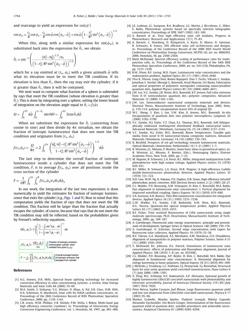
which for a ray emitted at (ro, fo) with a given azimuth f tellswhat its elevation must be to meet the TIR condition. If its
elevation is less than yc , then the ray may exit the cylinder; if it
is greater than yc , then it will be contained.We next want to compute what fraction of a sphere is subtended
by rays that meet the TIR condition (whose elevation is greater thanyc). This is done by integrating over a sphere, setting the lower boundof integration on the elevation angle equal to yc ¼ f ðfÞ
O¼Z 2p
0dfZ p�fc
yc
sinydy¼Z 2p
02cos ycdf
When we substitute the expression for yc (converting fromcosine to sine) and then divide by 4p steradian, we obtain thefraction of isotropic luminescence that does not meet the TIRcondition and originates from (ro, fo)
f ðro,foÞ ¼O4p¼ 2
Z 2p
0
n20=n2
1�r2o=R2 sin2 fo�f
� �1�r2
o=R2 sin2 fo�f� �
0@
1A
1=2
df
The last step to determine the overall fraction of isotropicluminescence inside a cylinder that does not meet the TIRcondition, F, is to average f(ro, fo) over all positions inside thecross section of the cylinder
F ¼1
pR2
Z 2p
0
Z R
0f ðro,foÞrodrodfo
In our work, the integration of the last two expressions is donenumerically to yield the estimates for fraction of isotropic lumines-cence that exits the cylinder (e.g., Figs. 1 and 9). Bear in mind that thiscomputation yields the fraction of rays that does not meet the TIRcondition. This fraction will be larger than the fraction that actuallyescapes the cylinder, of course, because that rays that do not meet theTIR condition may still be reflected, based on the probabilities givenby Fresnel’s reflectivity equations.
References
[1] A.G. Imenes, D.R. Mills, Spectral beam splitting technology for increasedconversion efficiency in solar concentrating systems: a review, Solar EnergyMaterials and Solar Cells 84 (2004) 19–69.
[2] M.A. Smith, S. Sinharoy, V.G. Weizer, O. Khan, A. Pal, E.B. Clarc, D.M. Wilt,D.A. Scheiman, N. Mardesich, Solar cells for NASA rainbow concentrator, in:Proceedings of the 28th Conference Record of IEEE Photovoltaic SpecialistsConference, 2000, pp. 1139–1141.
[3] C.R. Lewis, W.M. Phillips, V.B. Shields, P.M. Stella, I. Bekey, Multi-band gaphigh efficiency converter (rainbow), in: Proceedings of Intersociety EnergyConversion Engineering Conference, vol. 1, Honolulu, HI, 1997, pp. 401–406.
[4] J.E. Ludman, J.L. Sampson, R.A. Bradbury, J.G. Martin, J. Riccobono, G. Sliker,E. Rallis, Photovoltaic systems based on spectrally selective holographicconcentrators, Proceedings of SPIE 1667 (1992) 182–189.
[5] A. Barnett et al., Very high efficiency solar cell modules, Progress inPhotovoltaics: Research and Applications 17(1) 75–83.
[6] A. Barnett, C. Honsberg, D. Kirkpatrick, S. Kurtz, D. Moore, D. Salzman,R. Schwartz, K. Emery, 50% efficient solar cell architectures and designs,in: Proceedings of the Conference Record of the 2006 IEEE Fourth WorldConference on Photovoltaic Energy Conversion, WCPEC-42, art. no. 4060203,2006, Honolulu, Hl, pp. 2560–2564.
[7] Mark McDonald, Spectral efficiency scaling of performance ratio for multi-junction cells, in: Proceedings of the Conference Record of the 34th IEEEPhotovoltaic Specialists Conference, 2009, art. no. 5411236, Philadelphia, PA,pp. 1215–1220.
[8] R.W. Olson, R.F. Loring, M.D. Fayer, Luminescent solar concentrators and thereabsorption problem, Applied Optics 20 (17) (1981) 2934–2940.
[9] Ylva K. Olsson, Gang Chen, Ronen Rapaport, Dan T. Fuchs, Vikram C. Sundar,Jonathan S. Steckel, Moungi G. Bawendi, Assaf Aharoni, Uri Banin, Fabricationand optical properties of polymeric waveguides containing nanocrystallinequantum dots, Applied Physics Letters 85 (19) (2004) 4469–4471.
[10] J.W. Lee, V.C. Sundar, J.R. Heine, M.G. Bawendi, K.F. Jensen, Full color emissionfrom II–VI semiconductor quantum dot—polymer composites, AdvancedMaterials 12 (2000) 1102–1105.
[11] J.W. Lee, Semiconductor nanocrystal composite materials and devices,Doctoral Thesis, Massachusetts Institute of Technology, June 2002. Note,p. 110–114: polymer encapsulation leaves 65% of original QY.
[12] W.C. Sheng, S. Kim, J. Lee, S.W. Kim, K. Jensen, M.G. Bawendi, In-situEncapsulation of quantum dots into polymer microspheres, Langmuir 22(2006) 3782–3790.
[13] V.C. Sundar, H.J. Eisler, Y.T. Chan, E.L. Thomas, M.G. Bawendi, Soft lithogra-phically embossed multilayered distributed feedback nanocrystal lasers,Advanced Materials (Weinheim, Germany)16, 23–24 (2004) 2137–2141.
[14] V.C. Sundar, H.J. Eisler, M.G. Bawendi, Room Temperature, Tunable gainmedia from novel II–VI nanocrystal-titania composite matrices, AdvancedMaterials (Weinheim, Germany) 14 (10) (2002) 739–743.
[15] R. Reisfeld, Prospects of sol–gel technology towards luminescent materials,Optical Materials (Amsterdam, Netherlands) 16 (1–2) (2001) 1–7.
[16] R. Winston, J.C. Minano, P. Benitez, Some basic ideas in geometrical optics, in:R. Winston, J.C. Minano, P. Benitez (Eds.), Nonimaging Optics, ElsevierAcademic Press, New York, 2005, pp. 7–23.
[17] M. Ilegems, B. Schwartz, L.A. Koszi, R.C. Miller, Integrated multijunction GaAsphotodetector with high output voltage, Applied Physics Letters 33 (1978)629–631.
[18] R.C. Miller, B. Schwartz, L.A. Koszi, W.R. Wagner, A high-efficiency GaAlAsdouble-heterostructure photovoltaic detector, Applied Physics Letters 33(1978) 721–723.
[19] H.D. Law, W.W. Ng, K. Nakano, P.D. Dapkus, D.R. Stone, High efficiency InGaAsPphotovoltaic power converter, IEEE Electron Device Letters 2 (2) (1981) 26–27.
[20] C.L. Mulder, P.D. Reusswig, A.M. Velazquez, H. Kim, C. Rotschild, M.A. Baldo,Dye alignment in luminescent solar concentrators: I. Vertical alignment forimproved wavefluid coupling, Optics Express 18 (S1) (2010) A79–A90.
[21] S.A. Evenson, A.H. Rawicz, Thin-film luminescent concentrators for integrateddevices, Applied Optics 34 (31) (1995) 7231–7238.
[22] G.W. Walker, V.C. Sundar, C.M. Rudzinski, A.W. Wun, M.G. Bawendi,D.G. Nocera, Quantum-dot optical temperature probes, Applied PhysicalLetters 83 (17) (2003) 3555–3557.
[23] B.F. Fisher, Time resolved fluorescence of CdSe nanocrystals using singlemolecule spectroscopy, Ph.D. Dissertation, Massachusetts Institute of Tech-nology, 2005, pp. 184–187.
[24] A. Goetzberger, Fluorescent solar energy concentrators: principle and present-state-of-development, Springer Series in Optical Sciences 140 (2009) 159–176.
[25] A. Goetzberger, O. Schirmer, Second stage concentration with tapers forfluorescent solar collectors, Applied Physics 19 (1979) 53–58.
[26] R.V. Talroze, G.A. Shandryuk, A.S. Merekalov, A.M. Shatalova, O.A. Otmakhova,Alignment of nanoparticles in polymer matrices, Polymer Science, Series A 51(11) (2009) 1930–1939.
[27] S. McDowall, B.L. Johnson, D.L. Patrick, Simulations of luminescent solarconcentrators: effects of polarization and fluorophore alignment, Journal ofApplied Physics 108 (2010) 1–8 (art. no. 053508).
[28] C.L. Mulder, P.D. Reusswig, A.P. Beyler, H. Kim, C. Rotschild, M.A. Baldo, Dyealignment in luminescent solar concentrators: II. Horizontal alignment forenergy harvesting in linear polarizers, Optical Express 18 (S1) (2010) A91–A99.
[29] J. Mcbride, J. Treadway, L.C. Feldman, S.J. Pennycook, S.J. Rosenthal, Structuralbasis for near unity quantum yield core/shell nanostructures, Nano Letters 6(7) (July 2006) 1496–1501.
[30] X. Peng, M.C. Schlamp, A.V. Kadavanich, A.P. Alivisatos, Epitaxial growth ofhighly luminescent CdSe/CdS core/shell nanocrystals with photostability andelectronic accessibility, Journal of American Chemical Society 119 (30) (July1997) 7019–7029.
[31] Peter Reissa, Sophie Carayon, Joel Bleuse, Large fluorescence quantum yieldand low size dispersion from CdSe/ZnSe core/shell nanocrystals, Physica E 17(2003) 95–96.
[32] Markus Grabolle, Monika Spieles, Vladimir Lesnyak, Nikolai Gaponik,Alexander Eychmuller, Ute Resch-Genger, Determination of the fluorescencequantum yield of quantum dots: suitable procedures and achievable uncer-tainties, Analytical Chemistry 81 (2009) 6285–6294.

B. Fisher, J. Biddle / Solar Energy Materials & Solar Cells 95 (2011) 1741–1755 1755
[33] Brian L. Wehrenberg, Congjun Wang, Philippe Guyot-Sionnest, Interband andintraband optical studies of PbSe colloidal quantum dots, Journal of PhysicalChemistry B 106 (2002) 10634–10640.
[34] Peter M. Allen, Wenhao Liu, Vikash P. Chauhan, Jungmin Lee, Alice Y. Ting,
Dai Fukumura, Rakesh K. Jain, Moungi G. Bawendi, InAs(ZnCdS) quantumdots optimized for biological imaging in the near-infrared, Journal ofAmerican Chemical Society 132 (2010) 470–471.
[35] J.F. Geisz, D.J. Friedman, J.S. Ward, A. Duda, W.J. Olavarria, T.E. Moriarty,J.T. Kiehl, M.J. Romero, A.G. Norman, K.M. Jones, 40.8% efficient invertedtriple-junction solar cell with two independently metamorphic junctions,
Applied Physics Letters 93 (2008) (art. no. 123505).
[36] L.M. Fraas, J.E. Samaras, H.X. Huang, L.M. Minkin, J.E. Avery, W.E. Daniels,S. Hui, TPV generators using the radiant tube burner configuration, in:
Proceedings of the 17th European Photovoltaic Solar Energy ConferenceExhibition, Munich, Germany, 2001, pp. 1–4.
[37] David M. Wilt, Navid S. Fatemi, Richard W. Hoffman, Jr., Phillip P. Jenkins,David Scheiman, Roland Lowe, Geoffrey A. Landis, InGaAs PV device deve-lopment for TPV power systems, in: Proceedings of the First Conference onThermophotovoltaic Generation of Electricity, Copper Mountain, Colorado,24–26 July 1994, American Institute of Physics Conference Proceedings, vol.321, pp. 210–220.
[38] Tomoyuki Kumano, Katsunori Hanamura, A feasibility study on spectralcontrol using piled AR-coated quartz filters for application to TPV, in:C. Algora, V. Corregidor (Eds.), Proceedings of the Seventh Conference onThermophotovoltaic Generation of Electricity, Madrid, Spain, 25–27 Septem-ber 2006, American Institute of Physics Conference Proceedings, vol. 890,2007, pp. 68–76.