ludes to engineering graphics - static.sdcpublications.com
TRANSCRIPT

ACCESS CODEUNIQUE CODE INSIDE
A Concise Introduction to Engineering G
raphicsIncluding W
orksheet Series A
A Concise Introduction to Engineering GraphicsIncluding Worksheet Series ASixth Edition
Timothy J. Sexton
SDCP U B L I C AT I O N S www.SDCpublications.com
Better Textbooks. Lower Prices.
Includes
Video Lectures & Digital
Copy of Technical Graphics

Visit the following websites to learn more about this book:
Powered by TCPDF (www.tcpdf.org)

Chapter 6 Auxiliary Views
35
Chapter 6 Auxiliary Views Visualizing a Primary Auxiliary View:
For many objects the six principal views do not always describe an object’s true shape. If the object contains an inclined surface, you need an additional view called a primary auxiliary view. Figure AUX 1 illustrates an example of an object with the inclined surface A. Surface A appears as an edge view in the front view and as a foreshortened plane in both the top and right views. But the true size and shape (TSS) of surface A is missing. In order to see the TSS of surface A you need to view surface A orthographically (i.e., at a right angle). Figure AUX 2 illustrates the line of sight necessary to obtain the TSS of surface A.
Figure AUX 1: Surface A is in edge view in the front and foreshortened in the top and right views.
Figure AUX 2: The front view shows surface A in edge view and the line of sight necessary to produce an orthographic TSS view of surface A.
Auxiliary views should be visualized using the
“plastic box” as was done when visualizing the principal views of a multiview drawing. Figure AUX 3A shows our object in a plastic box made up of only three principal views. To obtain the TSS of the inclined surface, a plastic plane must be parallel to the inclined plane as illustrated in Figure AUX 3B. Figure AUX 3C shows the auxiliary plane of projection partially rotated about the front view. Figure AUX 4 shows the auxiliary view after a complete 90° rotation. As illustrated in Figure AUX 4, the auxiliary view must stay aligned with the view it is rotated about, i.e., it must maintain projectability.
Figure AUX 3: A) Planes of projection for the Top, Front, and Right views, B) a plane of projection is placed parallel to the inclined surface, C) the auxiliary plane is revolving about the front view.
EV ofSurface A
Line o
f Sigh
t
Front
Aux
AuxPlane
(A) (B)
(C)
Front
Top
Right
Isometric
A
A
EV of A
A
Inclinedsurface
Chapter 6 Auxiliary Views
36
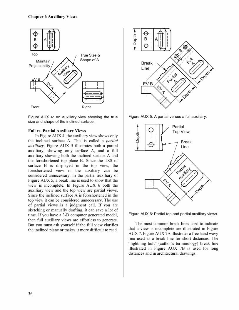
Figure AUX 4: An auxiliary view showing the true size and shape of the inclined surface. Full vs. Partial Auxiliary Views
In Figure AUX 4, the auxiliary view shows only the inclined surface A. This is called a partial auxiliary. Figure AUX 5 illustrates both a partial auxiliary, showing only surface A, and a full auxiliary showing both the inclined surface A and the foreshortened top plane B. Since the TSS of surface B is displayed in the top view, the foreshortened view in the auxiliary can be considered unnecessary. In the partial auxiliary of Figure AUX 5, a break line is used to show that the view is incomplete. In Figure AUX 6 both the auxiliary view and the top view are partial views. Since the inclined surface A is foreshortened in the top view it can be considered unnecessary. The use of partial views is a judgment call. If you are sketching or manually drafting, it can save a lot of time. If you have a 3-D computer generated model, then full auxiliary views are effortless to generate. But you must ask yourself if the full view clarifies the inclined plane or makes it more difficult to read.
Figure AUX 5: A partial versus a full auxiliary.
Figure AUX 6: Partial top and partial auxiliary views. The most common break lines used to indicate
that a view is incomplete are illustrated in Figure AUX 7. Figure AUX 7A illustrates a free hand wavy line used as a break line for short distances. The “lightning bolt” (author’s terminology) break line illustrated in Figure AUX 7B is used for long distances and in architectural drawings.
Top
Right
Auxilia
ry
View
True Size &Shape of A
EV BEV A
B A
MaintainProjectability
Front
Partial
Full
EV A
Dep
th
Depth
Depth
B A
EV B A
B
ABreakLine
Partial
EV A
Dep
th
Depth
PartialTop View
BreakLine
Auxilia
ry
Chapter 6 Auxiliary Views
37
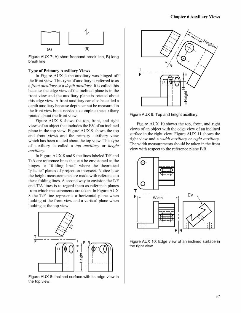
Figure AUX 7: A) short freehand break line, B) long break line. Type of Primary Auxiliary Views
In Figure AUX 4 the auxiliary was hinged off the front view. This type of auxiliary is referred to as a front auxiliary or a depth auxiliary. It is called this because the edge view of the inclined plane is in the front view and the auxiliary plane is rotated about this edge view. A front auxiliary can also be called a depth auxiliary because depth cannot be measured in the front view but is needed to complete the auxiliary rotated about the front view.
Figure AUX 8 shows the top, front, and right views of an object that includes the EV of an inclined plane in the top view. Figure AUX 9 shows the top and front views and the primary auxiliary view which has been rotated about the top view. This type of auxiliary is called a top auxiliary or height auxiliary.
In Figure AUX 8 and 9 the lines labeled T/F and T/A are reference lines that can be envisioned as the hinges or “folding lines” where the theoretical “plastic” planes of projection intersect. Notice how the height measurements are made with reference to these folding lines. A second way to envision the T/F and T/A lines is to regard them as reference planes from which measurements are taken. In Figure AUX 8 the T/F line represents a horizontal plane when looking at the front view and a vertical plane when looking at the top view.
Figure AUX 8: Inclined surface with its edge view in the top view.
Figure AUX 9: Top and height auxiliary.
Figure AUX 10 shows the top, front, and right views of an object with the edge view of an inclined surface in the right view. Figure AUX 11 shows the right view and a width auxiliary or right auxiliary. The width measurements should be taken in the front view with respect to the reference plane F/R.
Figure AUX 10: Edge view of an inclined surface in the right view.
(A) (B)
F R
Hei
ght
EV
H
TF
AT
TF
Hei
ghtH
HeightH
TF
F R
EVWidth

Chapter 6 Auxiliary Views
38
Figure AUX 11: Right or depth auxiliary. Reverse Construction:
When drafting by hand or using a 2-D CAD system, it is often easier to draw the auxiliary first and then project points back to the principal views. Figure AUX 12 illustrates the procedure: 1. draw the front view, partial auxiliary view, and
the right view except the irregular curve; 2. in the auxiliary view, layout points a, b, c, d, and
e (every 15°); 3. project points a – e back onto the edge view of
the inclined surface in the front view; 4. project points a – e from the front view to the
right view; 5. lay out points a – e using their corresponding
measurements from the top view, point a and e use distance x, point b and d use distance y, and point c uses distance z.
6. connect points w, a-e, and v with a french curve for manual drawing or use the spline function in a 2-D CAD system.
Figure AUX 12: The curve in the right view is generated by projecting the points a, b, c, d, and e from the auxiliary view to the EV in the front view and then to the right view. Then the distances x, y, and z are transferred from the auxiliary view to the right view.
Successive Auxiliaries:
The true size and shape (TSS) of an inclined plane can be found by a single 90° rotation about an edge view located in one of the principle views. But finding the TSS of an oblique plane takes one additional 90° rotation or successive auxiliary called a secondary auxiliary.
In Figure AUX 13 there is the front, top, primary auxiliary A1 and secondary auxiliary A2. The elliptical holes and arcs of the top and front views will need to be constructed after the TSS oblique plane in view A2 is laid out. The following steps are a guide to construct the four views: 1. layout as much of the front and top views as
possible (the elliptical portions will have to wait for now),
2. draw the folding line T/A1 perpendicular to the TL line 1,2 in the top view. This gives you the edge view of both surfaces and the true angle between the surfaces. Then layout primary auxiliary A1 using height measurements X from the folding line T/F into the front view,
3. draw the folding line A1/A2 parallel to the EV of the oblique surface, then layout the true circle and arc in the secondary auxiliary A2 using
AR
EV
F R
Width
Width
xyz
xy
z
a bc
e
d
abc
e d
ab
c
ed EV
w
v

Chapter 6 Auxiliary Views
39
measurements Y from the folding line A1/T into the top view,
4. from the secondary auxiliary view A2 project the points 3, 4, 5, 6, and 7 and the center hole back onto the EV in the primary auxiliary A1 and complete the primary auxiliary A1,
5. project point 3, 4, 5, 6, and 7 from the primary auxiliary A1 into the top view and locate these points using Y dimensions taken from folding line A1/A2 into the secondary auxiliary A2,
6. project points 3, 4, 5, 6, and 7 from the top view into the front view and locate these points using the height X dimensions taken from folding line T/A1 into the primary auxiliary A1,
7. complete the hole in a similar manner, 8. use a french curve or the CAD ellipse function
to construct the elliptical hole and arcs.
To find the dimensions needed to plot points on auxiliary views, place your finger on the auxiliary view then jump back over two successive folding lines putting your finger on each view as you jump. Obtain your measurements by measuring from the second folding line jumped to the view your finger is touching.
Figure AUX 13: Primary auxiliary A1 displays the EV of the oblique surface and secondary auxiliary A2 displays the TSS of the oblique plane. Dihedral Angles:
A dihedral angle is the angle formed when two planes intersect. Figure AUX 14A shows an example of a V block (used to cradle cylindrical stock in a machine shop when the cylinder, for example, is to receive a drilled hole) with the line 1, 2 forming the line of intersection between the planes W and X. In Figure 14A the line of intersection 1,2 is true length in the top view and shows as a point projection 1,2 in the front view. When you have the point projection of the true length line of intersection (line 1,2) between planes X and W, the view will display the edge view of the two intersecting planes allowing you to see the true dihedral angle.
5
TA1 A1
A2
TF
TTS
EV
12
1
2
2,1
Y
Y
X
TL
34
56
2
1
345
6
34
6
X
7
54,63,7
7
7
TrueAngle
Chapter 6 Auxiliary Views
40
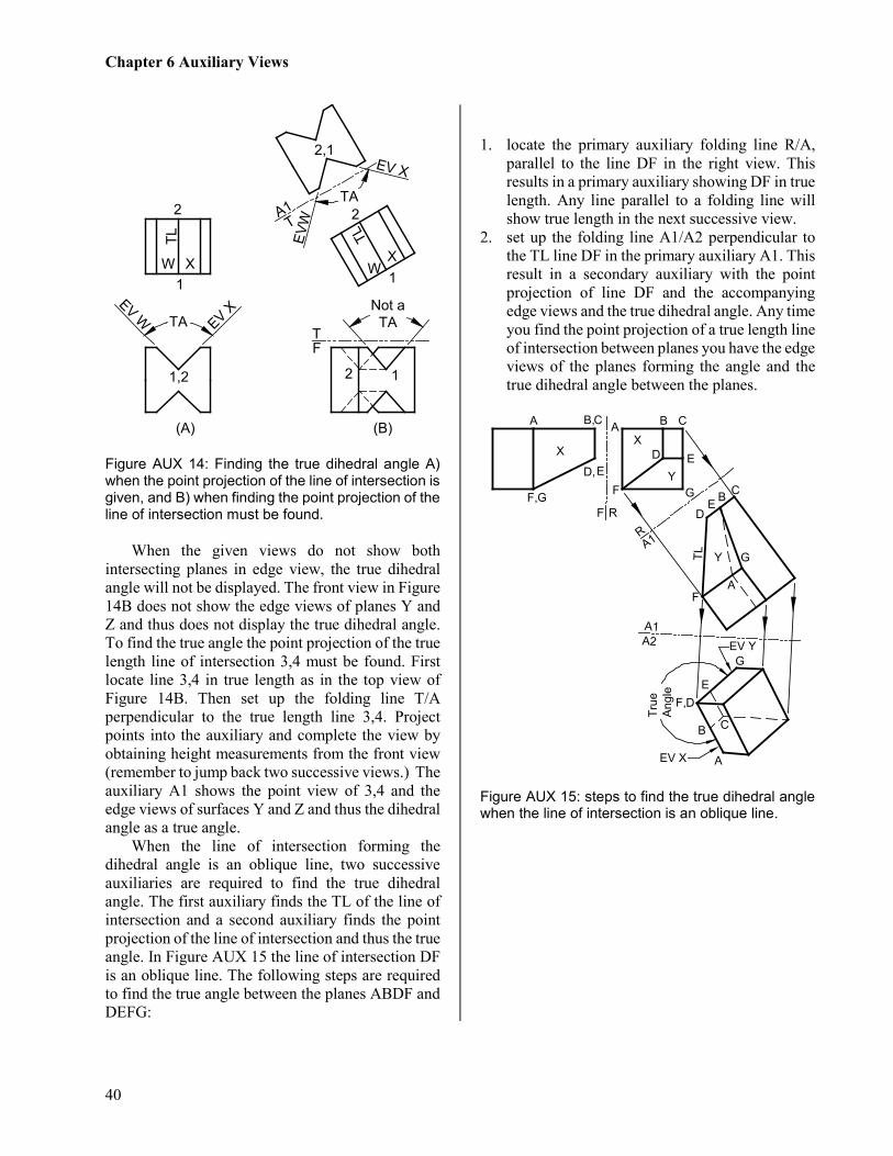
Figure AUX 14: Finding the true dihedral angle A) when the point projection of the line of intersection is given, and B) when finding the point projection of the line of intersection must be found.
When the given views do not show both
intersecting planes in edge view, the true dihedral angle will not be displayed. The front view in Figure 14B does not show the edge views of planes Y and Z and thus does not display the true dihedral angle. To find the true angle the point projection of the true length line of intersection 3,4 must be found. First locate line 3,4 in true length as in the top view of Figure 14B. Then set up the folding line T/A perpendicular to the true length line 3,4. Project points into the auxiliary and complete the view by obtaining height measurements from the front view (remember to jump back two successive views.) The auxiliary A1 shows the point view of 3,4 and the edge views of surfaces Y and Z and thus the dihedral angle as a true angle.
When the line of intersection forming the dihedral angle is an oblique line, two successive auxiliaries are required to find the true dihedral angle. The first auxiliary finds the TL of the line of intersection and a second auxiliary finds the point projection of the line of intersection and thus the true angle. In Figure AUX 15 the line of intersection DF is an oblique line. The following steps are required to find the true angle between the planes ABDF and DEFG:
1. locate the primary auxiliary folding line R/A,
parallel to the line DF in the right view. This results in a primary auxiliary showing DF in true length. Any line parallel to a folding line will show true length in the next successive view.
2. set up the folding line A1/A2 perpendicular to the TL line DF in the primary auxiliary A1. This result in a secondary auxiliary with the point projection of line DF and the accompanying edge views and the true dihedral angle. Any time you find the point projection of a true length line of intersection between planes you have the edge views of the planes forming the angle and the true dihedral angle between the planes.
Figure AUX 15: steps to find the true dihedral angle when the line of intersection is an oblique line.
TLTL
1
2
1
2
2,1
1,2 12
FT
TA1
WXW X
(A) (B)
EV XEV W
EV X
EVW
Not aTA
TA
TA
EV YTr
ueAn
gle
EV X
X
Y
Y
X
F R
A1
A1A2
R
A B C
D E
F G
TL
A B,C
D,E
F,GD
F
G
A
B
DF,
G
BE
A
E
C
C

AUXILIARY VIEWS
Sketch
Name:
ID#:
US CUST
Lab Hr:
T. S
exto
n Ó
AU
X-1
A.d
wg
AUX-1A
A
F
FT
A
T
FT
Give
n: T
op
a
nd
F
ro
nt V
ie
ws
Ske
tch
: F
ull A
uxilia
ry (S
ho
w H
id
de
n L
in
es)
Fro
nt
Give
n: T
op
a
nd
F
ro
nt V
ie
ws
Ske
tch
: P
artia
l A
uxilia
ry (S
ho
w H
id
de
n L
in
es)
Fro
nt

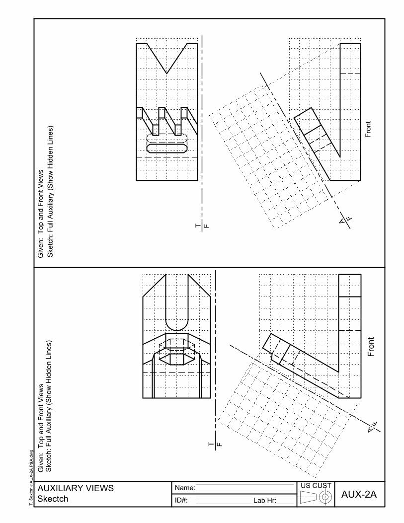
AUXILIARY VIEWS
Skectch
Name:
ID#:
US CUST
Lab Hr:
Ó
AUX-2A
Ske
tch
: F
ull A
uxilia
ry (S
ho
w H
id
de
n L
in
es)
Front
Give
n: T
op
a
nd
F
ro
nt V
ie
ws
T
F
A
F
T. S
exton
AU
X-2A
P
&A
.dw
g
Ske
tch
: F
ull A
uxilia
ry (S
ho
w H
id
de
n L
in
es)
Fro
nt
Give
n: T
op
a
nd
F
ro
nt V
ie
ws
T
F
A
F
