ltp5901-ipa/ltp5902-ipa - smartmesh ip access point (ap ... · ltp5902-ipa is the ip access point...
TRANSCRIPT

LTP5901-IPA/LTP5902-IPA
159012ipaf
For more information www.linear.com/LTP5901-IPA or www.linear.com/LTP5902-IPA
Typical applicaTion
neTwork FeaTures DescripTion
SmartMesh IP Access Point (AP) Mote 2.4GHz 802.15.4e Wireless AP Mote
lTp5901/2-ipa FeaTures
n Complete Radio Transceiver, Embedded Processor, and Networking Software for Forming a Self-Healing Mesh Network
n SmartMesh® Networks Incorporate: n Time Synchronized Network-Wide Scheduling n Per Transmission Frequency Hopping n Redundant Spatially Diverse Topologies n Network-Wide Reliability and Power Optimization n NIST Certified Security
n SmartMesh Networks Deliver: n >99.999% Network Reliability Achieved in the
Most Challenging RF Environments n Sub 50µA Routing Nodes
n Compliant to 6LoWPAN Internet Protocol (IP) and IEEE 802.15.4e Standards
n Provides Network Access Point Radio Functions for SmartMesh VManager
n Supports Networks of Thousands of Nodes, in Combination with VManager Network Manager Software
n Enables Redundant Network Ingress/Egress with Automatic Failover
n RF Modular Certification Include USA, Canada, Japan, EU, Taiwan, Korea, India, Australia and New Zealand
n PCB Assembly with Chip Antenna (LTP5901-IPA) or with MMCX Antenna Connector (LTP5902-IPA)
SmartMesh IP™ wireless sensor networks are self man-aging, low power internet protocol (IP) networks built from wireless nodes called motes. The LTP™5901-IPA/LTP5902-IPA is the IP Access Point Mote™ (AP Mote™) in the Eterna®* family of IEEE 802.15.4e system-on-chip (SoC) solutions, featuring a highly integrated, low power radio design by Dust Networks® as well as an ARM Cortex-M3 32-bit microprocessor running Dust’s embed-ded SmartMesh IP networking software. SmartMesh IP software provided with the LTP5901/LTP5902-IPA is a fully tested and validated binary image.
Based on the IETF 6LoWPAN and IEEE-802.15.4e stan-dards, the LTP5901/LTP5902-IPA, executing SmartMesh IP Access Point Mote software, provides a data ingress/egress point via a two wire UART interface. In combination with the VManager™ software the LTP5901/LTP5902-IPA enables very large scale networks with full redundancy and automatic failover, in addition to providing a means to scale network throughput. With Dust’s time-synchronized SmartMesh IP networks, all motes in the network may route, source or terminate data, while providing many years of battery-powered operation. L, LT, LTC, LTM, Linear Technology, Dust, Dust Networks, Eterna, SmartMesh and the Linear logo are registered trademarks and LTP, SmartMesh IP, the Dust Networks logo, VManager, Access Point Mote and AP Mote are trademarks of Linear Technology Corporation. All other trademarks are the property of their respective owners. Protected by U.S. Patents, including 7375594, 7420980, 7529217, 7791419, 7881239, 7898322, 8222965. * Eterna is Dust Networks’ low power radio SoC architecture.
59012IPA TA01
20MHz
SENSOR
IN+
IN–
SPILTC2379-18
32kHz
LTC5800-IPM
SPI
ANTENNA
vManager +HOST APPLICATION
µCONTROLLER
UART ETHERNET
LTP5901-IPA/LTP5902-IPA
259012ipaf
For more information www.linear.com/LTP5901-IPA or www.linear.com/LTP5902-IPA
Table oF conTenTs Network Features .......................................... 1LTP5901/2-IPA Features .................................. 1Typical Application ........................................ 1Description.................................................. 1SmartMesh Network Overview ........................... 3Absolute Maximum Ratings .............................. 4Pin Configuration .......................................... 4Order Information .......................................... 5Recommended Operating Conditions ................... 5Radio Specifications ...................................... 6Radio Receiver Characteristics .......................... 6Radio Transmitter Characteristics ....................... 7Digital I/O Characteristics ................................ 7Temperature Sensor Characteristics .................... 7System Characteristics ................................... 8UART AC Characteristics .................................. 8TIMEn PPS AC Characteristics ........................... 8Flash AC Characteristics .................................. 9Flash SPI Slave AC Characteristics ..................... 9Typical Performance Characteristics .................. 11Pin Functions .............................................. 14
Operation................................................... 16Network Management options ................................ 16VManager + AP Mote Benefits ................................ 16AP Mote / VManager Communication ..................... 16AP Mote Time Synchronization ............................... 16Networking ............................................................. 17Power Supply .......................................................... 18Supply Monitoring and Reset ................................. 18Precision Timing ..................................................... 18Time References ..................................................... 18Radio ...................................................................... 18UARTs ..................................................................... 19API UART Protocol ................................................. 19CLI UART ................................................................ 19Security .................................................................. 19Software Installation ............................................... 19State Diagram .........................................................20Regulatory and Standards Compliance ...................22Soldering Information .............................................22
Related Documentation .................................. 23Package Description ..................................... 24Typical Application ....................................... 26Related Parts .............................................. 26
LTP5901-IPA/LTP5902-IPA
359012ipaf
For more information www.linear.com/LTP5901-IPA or www.linear.com/LTP5902-IPA
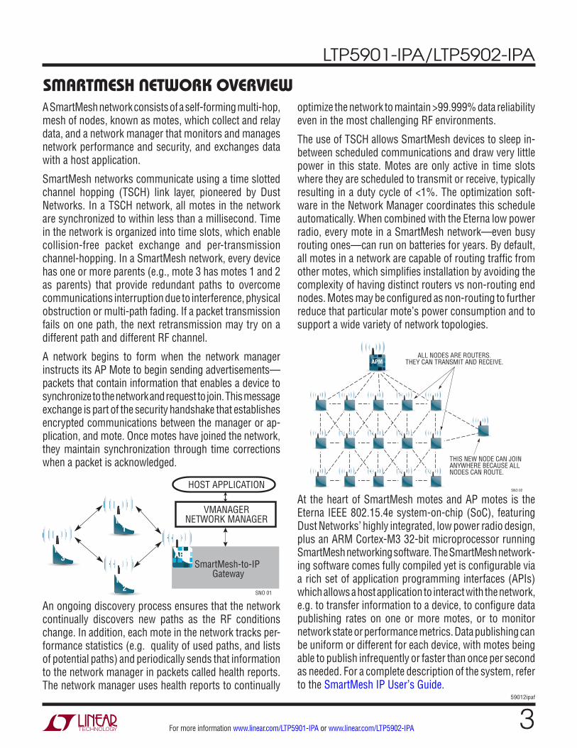
smarTmesh neTwork overviewA SmartMesh network consists of a self-forming multi-hop, mesh of nodes, known as motes, which collect and relay data, and a network manager that monitors and manages network performance and security, and exchanges data with a host application.
SmartMesh networks communicate using a time slotted channel hopping (TSCH) link layer, pioneered by Dust Networks. In a TSCH network, all motes in the network are synchronized to within less than a millisecond. Time in the network is organized into time slots, which enable collision-free packet exchange and per-transmission channel-hopping. In a SmartMesh network, every device has one or more parents (e.g., mote 3 has motes 1 and 2 as parents) that provide redundant paths to overcome communications interruption due to interference, physical obstruction or multi-path fading. If a packet transmission fails on one path, the next retransmission may try on a different path and different RF channel.
A network begins to form when the network manager instructs its AP Mote to begin sending advertisements—packets that contain information that enables a device to synchronize to the network and request to join. This message exchange is part of the security handshake that establishes encrypted communications between the manager or ap-plication, and mote. Once motes have joined the network, they maintain synchronization through time corrections when a packet is acknowledged.
optimize the network to maintain >99.999% data reliability even in the most challenging RF environments.
The use of TSCH allows SmartMesh devices to sleep in-between scheduled communications and draw very little power in this state. Motes are only active in time slots where they are scheduled to transmit or receive, typically resulting in a duty cycle of <1%. The optimization soft-ware in the Network Manager coordinates this schedule automatically. When combined with the Eterna low power radio, every mote in a SmartMesh network—even busy routing ones—can run on batteries for years. By default, all motes in a network are capable of routing traffic from other motes, which simplifies installation by avoiding the complexity of having distinct routers vs non-routing end nodes. Motes may be configured as non-routing to further reduce that particular mote’s power consumption and to support a wide variety of network topologies.
An ongoing discovery process ensures that the network continually discovers new paths as the RF conditions change. In addition, each mote in the network tracks per-formance statistics (e.g. quality of used paths, and lists of potential paths) and periodically sends that information to the network manager in packets called health reports. The network manager uses health reports to continually
At the heart of SmartMesh motes and AP motes is the Eterna IEEE 802.15.4e system-on-chip (SoC), featuring Dust Networks’ highly integrated, low power radio design, plus an ARM Cortex-M3 32-bit microprocessor running SmartMesh networking software. The SmartMesh network-ing software comes fully compiled yet is configurable via a rich set of application programming interfaces (APIs) which allows a host application to interact with the network, e.g. to transfer information to a device, to configure data publishing rates on one or more motes, or to monitor network state or performance metrics. Data publishing can be uniform or different for each device, with motes being able to publish infrequently or faster than once per second as needed. For a complete description of the system, refer to the SmartMesh IP User’s Guide.
HOST APPLICATION
SNO 01
VMANAGERNETWORK MANAGER
Mote2
Mote1
Mote3 APM
SmartMesh-to-IP Gateway
ALL NODES ARE ROUTERS.THEY CAN TRANSMIT AND RECEIVE.
THIS NEW NODE CAN JOINANYWHERE BECAUSE ALLNODES CAN ROUTE.
SNO 02
APM
LTP5901-IPA/LTP5902-IPA
459012ipaf
For more information www.linear.com/LTP5901-IPA or www.linear.com/LTP5902-IPA
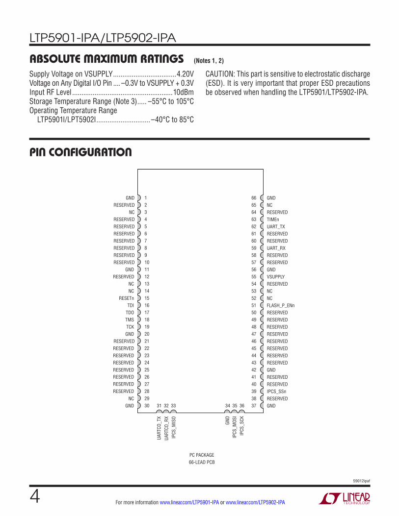
pin conFiguraTion
absoluTe maximum raTingsSupply Voltage on VSUPPLY ..................................4.20VVoltage on Any Digital I/O Pin .... –0.3V to VSUPPLY + 0.3VInput RF Level ......................................................10dBmStorage Temperature Range (Note 3) ..... –55°C to 105°COperating Temperature Range
LTP5901I/LPT5902I .............................–40°C to 85°C
(Notes 1, 2)
CAUTION: This part is sensitive to electrostatic discharge (ESD). It is very important that proper ESD precautions be observed when handling the LTP5901/LTP5902-IPA.
123456789101112131415161718192021222324252627282930
666564636261605958575655545352515049484746454443424140393837
GNDRESERVED
NCRESERVEDRESERVEDRESERVEDRESERVEDRESERVEDRESERVEDRESERVED
GNDRESERVED
NCNC
RESETnTDI
TDOTMSTCKGND
RESERVEDRESERVEDRESERVEDRESERVEDRESERVED
NCGND
GNDNCRESERVEDTIMEnUART_TXRESERVEDRESERVEDUART_RXRESERVEDRESERVEDGNDVSUPPLYRESERVEDNCNCFLASH_P_ENnRESERVEDRESERVEDRESERVEDRESERVEDRESERVEDRESERVEDRESERVEDRESERVEDGNDRESERVEDRESERVEDIPCS_SSnRESERVEDGND
IPCS
_MIS
OUA
RTCO
_RX
UART
CO_T
X
PC PACKAGE66-LEAD PCB
IPCS
_SCK
IPCS
_MOS
IGN
D
31 32 33 34 35 36
RESERVEDRESERVEDRESERVED
LTP5901-IPA/LTP5902-IPA
559012ipaf
For more information www.linear.com/LTP5901-IPA or www.linear.com/LTP5902-IPA
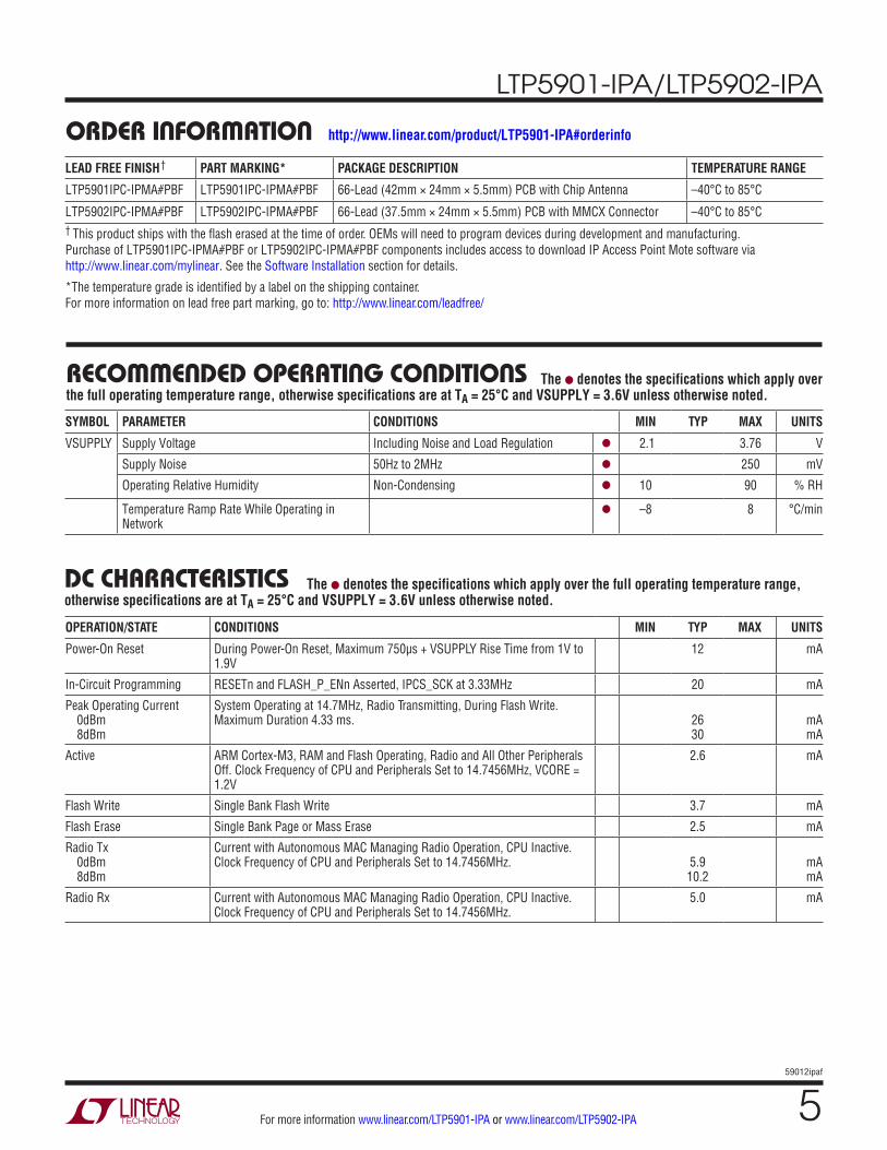
orDer inFormaTionLEAD FREE FINISH† PART MARKING* PACKAGE DESCRIPTION TEMPERATURE RANGE
LTP5901IPC-IPMA#PBF LTP5901IPC-IPMA#PBF 66-Lead (42mm × 24mm × 5.5mm) PCB with Chip Antenna –40°C to 85°C
LTP5902IPC-IPMA#PBF LTP5902IPC-IPMA#PBF 66-Lead (37.5mm × 24mm × 5.5mm) PCB with MMCX Connector –40°C to 85°C† This product ships with the flash erased at the time of order. OEMs will need to program devices during development and manufacturing. Purchase of LTP5901IPC-IPMA#PBF or LTP5902IPC-IPMA#PBF components includes access to download IP Access Point Mote software via http://www.linear.com/mylinear. See the Software Installation section for details.
*The temperature grade is identified by a label on the shipping container. For more information on lead free part marking, go to: http://www.linear.com/leadfree/
recommenDeD operaTing conDiTions
SYMBOL PARAMETER CONDITIONS MIN TYP MAX UNITS
VSUPPLY Supply Voltage Including Noise and Load Regulation l 2.1 3.76 V
Supply Noise 50Hz to 2MHz l 250 mV
Operating Relative Humidity Non-Condensing l 10 90 % RH
Temperature Ramp Rate While Operating in Network
l –8 8 °C/min
The l denotes the specifications which apply over the full operating temperature range, otherwise specifications are at TA = 25°C and VSUPPLY = 3.6V unless otherwise noted.
Dc characTerisTics
OPERATION/STATE CONDITIONS MIN TYP MAX UNITS
Power-On Reset During Power-On Reset, Maximum 750µs + VSUPPLY Rise Time from 1V to 1.9V
12 mA
In-Circuit Programming RESETn and FLASH_P_ENn Asserted, IPCS_SCK at 3.33MHz 20 mA
Peak Operating Current 0dBm 8dBm
System Operating at 14.7MHz, Radio Transmitting, During Flash Write. Maximum Duration 4.33 ms.
26 30
mA mA
Active ARM Cortex-M3, RAM and Flash Operating, Radio and All Other Peripherals Off. Clock Frequency of CPU and Peripherals Set to 14.7456MHz, VCORE = 1.2V
2.6 mA
Flash Write Single Bank Flash Write 3.7 mA
Flash Erase Single Bank Page or Mass Erase 2.5 mA
Radio Tx 0dBm 8dBm
Current with Autonomous MAC Managing Radio Operation, CPU Inactive. Clock Frequency of CPU and Peripherals Set to 14.7456MHz.
5.9
10.2
mA mA
Radio Rx Current with Autonomous MAC Managing Radio Operation, CPU Inactive. Clock Frequency of CPU and Peripherals Set to 14.7456MHz.
5.0 mA
The l denotes the specifications which apply over the full operating temperature range, otherwise specifications are at TA = 25°C and VSUPPLY = 3.6V unless otherwise noted.
http://www.linear.com/product/LTP5901-IPA#orderinfo
LTP5901-IPA/LTP5902-IPA
659012ipaf
For more information www.linear.com/LTP5901-IPA or www.linear.com/LTP5902-IPA
PARAMETER CONDITIONS MIN TYP MAX UNITS
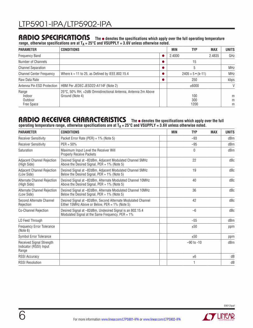
Frequency Band l 2.4000 2.4835 GHz
Number of Channels l 15
Channel Separation l 5 MHz
Channel Center Frequency Where k = 11 to 25, as Defined by IEEE.802.15.4 l 2405 + 5 • (k-11) MHz
Raw Data Rate l 250 kbps
Antenna Pin ESD Protection HBM Per JEDEC JESD22-A114F (Note 2) ±6000 V
Range Indoor Outdoor Free Space
25°C, 50% RH, +2dBi Omnidirectional Antenna, Antenna 2m Above Ground (Note 4)
100 300
1200
m m m
raDio speciFicaTions The l denotes the specifications which apply over the full operating temperature range, otherwise specifications are at TA = 25°C and VSUPPLY = 3.6V unless otherwise noted.
PARAMETER CONDITIONS MIN TYP MAX UNITS
Receiver Sensitivity Packet Error Rate (PER) = 1% (Note 5) –93 dBm
Receiver Sensitivity PER = 50% –95 dBm
Saturation Maximum Input Level the Receiver Will Properly Receive Packets
0 dBm
Adjacent Channel Rejection (High Side)
Desired Signal at –82dBm, Adjacent Modulated Channel 5MHz Above the Desired Signal, PER = 1% (Note 5)
22 dBc
Adjacent Channel Rejection (Low Side)
Desired Signal at –82dBm, Adjacent Modulated Channel 5MHz Below the Desired Signal, PER = 1% (Note 5)
19 dBc
Alternate Channel Rejection (High Side)
Desired Signal at –82dBm, Alternate Modulated Channel 10MHz Above the Desired Signal, PER = 1% (Note 5)
40 dBc
Alternate Channel Rejection (Low Side)
Desired Signal at –82dBm, Alternate Modulated Channel 10MHz Below the Desired Signal, PER = 1% (Note 5)
36 dBc
Second Alternate Channel Rejection
Desired Signal at –82dBm, Second Alternate Modulated Channel Either 15MHz Above or Below, PER = 1% (Note 5)
42 dBc
Co-Channel Rejection Desired Signal at –82dBm, Undesired Signal is an 802.15.4 Modulated Signal at the Same Frequency, PER = 1%
–6 dBc
LO Feed Through –55 dBm
Frequency Error Tolerance (Note 6)
±50 ppm
Symbol Error Tolerance ±50 ppm
Received Signal Strength Indicator (RSSI) Input Range
–90 to -10 dBm
RSSI Accuracy ±6 dB
RSSI Resolution 1 dB
raDio receiver characTerisTics The l denotes the specifications which apply over the full operating temperature range, otherwise specifications are at TA = 25°C and VSUPPLY = 3.6V unless otherwise noted.
LTP5901-IPA/LTP5902-IPA
759012ipaf
For more information www.linear.com/LTP5901-IPA or www.linear.com/LTP5902-IPA
PARAMETER CONDITIONS MIN TYP MAX UNITS
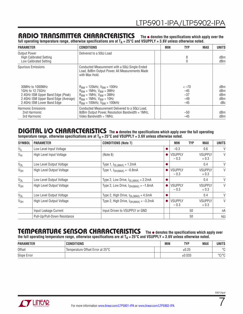
Output Power High Calibrated Setting Low Calibrated Setting
Delivered to a 50Ω Load 8 0
dBm dBm
Spurious Emissions 30MHz to 1000MHz 1GHz to 12.75GHz 2.4GHz ISM Upper Band Edge (Peak) 2.4GHz ISM Upper Band Edge (Average) 2.4GHz ISM Lower Band Edge
Conducted Measurement with a 50Ω Single-Ended Load, 8dBm Output Power. All Measurements Made with Max Hold. RBW = 120kHz, VBW = 100Hz RBW = 1MHz, VBW = 3MHz RBW = 1MHz, VBW = 3MHz RBW = 1MHz, VBW = 10Hz RBW = 100kHz, VBW = 100kHz
< –70 –45 –37 –49 –45
dBm dBm dBm dBm dBc
Harmonic Emissions 2nd Harmonic 3rd Harmonic
Conducted Measurement Delivered to a 50Ω Load, 8dBm Output Power, Resolution Bandwidth = 1MHz, Video Bandwidth = 1MHz.
–50 –45
dBm dBm
raDio TransmiTTer characTerisTics The l denotes the specifications which apply over the full operating temperature range, otherwise specifications are at TA = 25°C and VSUPPLY = 3.6V unless otherwise noted.
SYMBOL PARAMETER CONDITIONS (Note 7) MIN TYP MAX UNITS
VIL Low Level Input Voltage l –0.3 0.6 V
VIH High Level Input Voltage (Note 8) l VSUPPLY – 0.3
VSUPPLY + 0.3
V
VOL Low Level Output Voltage Type 1, IOL(MAX) = 1.2mA l 0.4 V
VOH High Level Output Voltage Type 1, IOH(MAX) = –0.8mA l VSUPPLY – 0.3
VSUPPLY + 0.3
V
VOL Low Level Output Voltage Type 2, Low Drive, IOL(MAX) = 2.2mA l 0.4 V
VOH High Level Output Voltage Type 2, Low Drive, IOH(MAX) = –1.6mA l VSUPPLY – 0.3
VSUPPLY + 0.3
V
VOL Low Level Output Voltage Type 2, High Drive, IOL(MAX) = 4.5mA l 0.4 V
VOH High Level Output Voltage Type 2, High Drive, IOH(MAX) = –3.2mA l VSUPPLY – 0.3
VSUPPLY + 0.3
V
Input Leakage Current Input Driven to VSUPPLY or GND 50 nA
Pull-Up/Pull-Down Resistance 50 kΩ
DigiTal i/o characTerisTics The l denotes the specifications which apply over the full operating temperature range, otherwise specifications are at TA = 25°C and VSUPPLY = 3.6V unless otherwise noted.
PARAMETER CONDITIONS MIN TYP MAX UNITS
Offset Temperature Offset Error at 25°C ±0.25 °C
Slope Error ±0.033 °C/°C
TemperaTure sensor characTerisTics The l denotes the specifications which apply over the full operating temperature range, otherwise specifications are at TA = 25°C and VSUPPLY = 3.6V unless otherwise noted.
LTP5901-IPA/LTP5902-IPA
859012ipaf
For more information www.linear.com/LTP5901-IPA or www.linear.com/LTP5902-IPA
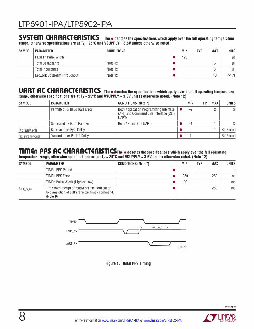
sysTem characTerisTics The l denotes the specifications which apply over the full operating temperature range, otherwise specifications are at TA = 25°C and VSUPPLY = 3.6V unless otherwise noted.
SYMBOL PARAMETER CONDITIONS (Note 7) MIN TYP MAX UNITS
Permitted Rx Baud Rate Error Both Application Programming Interface (API) and Command Line Interface (CLI) UARTs
l –2 2 %
Generated Tx Baud Rate Error Both API and CLI UARTs l –1 1 %
tRX_INTERBYTE Receive Inter-Byte Delay l 1 Bit Period
tTX_INTERPACKET Transmit Inter-Packet Delay l 1 Bit Period
uarT ac characTerisTics The l denotes the specifications which apply over the full operating temperature range, otherwise specifications are at TA = 25°C and VSUPPLY = 3.6V unless otherwise noted. (Note 12)
SYMBOL PARAMETER CONDITIONS MIN TYP MAX UNITS
RESETn Pulse Width l 125 µs
Total Capacitance Note 12 l 6 µF
Total Inductance Note 12 l 3 µH
Network Upstream Throughput Note 12 l 40 Pkts/s
SYMBOL PARAMETER CONDITIONS (Note 7) MIN TYP MAX UNITS
TIMEn PPS Period l 1 s
TIMEn PPS Error l -250 250 ns
TIMEn Pulse Width (High or Low) l 100 ms
tRFT_to_ST Time from receipt of readyForTime notification to completion of setParameter<time> command.(Note 9)
l 250 ms
Timen pps ac characTerisTics The l denotes the specifications which apply over the full operating temperature range, otherwise specifications are at TA = 25°C and VSUPPLY = 3.6V unless otherwise noted. (Note 12)
Figure 1. TIMEn PPS Timing
UART_TX
TIMEn
tRFT_to_ST
5800IPA F01
UART_RX
LTP5901-IPA/LTP5902-IPA
959012ipaf
For more information www.linear.com/LTP5901-IPA or www.linear.com/LTP5902-IPA
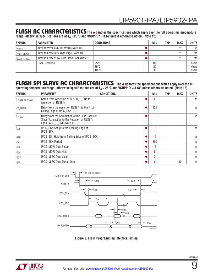
Flash ac characTerisTics The l denotes the specifications which apply over the full operating temperature range, otherwise specifications are at TA = 25°C and VSUPPLY = 3.6V unless otherwise noted. (Note 12)
Flash spi slave ac characTerisTics The l denotes the specifications which apply over the full operating temperature range, otherwise specifications are at TA = 25°C and VSUPPLY = 3.6V unless otherwise noted. (Note 12)
Figure 2. Flash Programming Interface Timing
5800IPA F02
IPCS_SCK
IPCS_MOSI
IPCS_SSn
RESETn
FLASH_P_ENntFP_EN_TO_RESET
tFP_ENTER
tSSS
tCK
tSSH
tFP_EXIT
tDIStDIH
tDOV tOFFIPCS_MISO
SYMBOL PARAMETER CONDITIONS MIN TYP MAX UNITS
tFP_EN_to_RESET Setup from Assertion of FLASH_P_ENn to Assertion of RESETn
l 0 ns
tFP_ENTER Delay from the Assertion RESETn to the First Falling Edge of IPCS_SSn
l 125 µs
tFP_EXIT Delay from the Completion of the Last Flash SPI Slave Transaction to the Negation of RESETn and FLASH_P_ENn (Note 11)
l 10 µs
tSSS IPCS_SSn Setup to the Leading Edge of IPCS_SCK
l 15 ns
tSSH IPCS_SSn Hold from Trailing Edge of IPCS_SCK l 15 ns
tCK IPCS_SCK Period l 300 ns
tDIS IPCS_MOSI Data Setup l 15 ns
tDIH IPCS_MOSI Data Hold l 5 ns
tDOV IPCS_MISO Data Valid l 3 ns
tOFF IPCS_MISO Data Three-State l 0 30 ns
SYMBOL PARAMETER CONDITIONS MIN TYP MAX UNITS
tWRITE Time to Write a 32-Bit Word (Note 10) l 21 µs
tPAGE_ERASE Time to Erase a 2k Byte Page (Note 10) l 21 ms
tMASS_ERASE Time to Erase 256k Byte Flash Bank (Note 10) l 21 ms
Data Retention 25°C 85°C 105°C
100 20 8
Years Years Years

LTP5901-IPA/LTP5902-IPA
1059012ipaf
For more information www.linear.com/LTP5901-IPA or www.linear.com/LTP5902-IPA
Note 1: Stresses beyond those listed under Absolute Maximum Ratings may cause permanent damage to the device. Exposure to any Absolute Maximum Rating condition for extended periods may affect device reliability and lifetime.Note 2: ESD (electrostatic discharge) sensitive device. ESD protection devices are used extensively internal to Eterna. However, high electrostatic discharge can damage or degrade the device. Use proper ESD handling precautions.Note 3: Extended storage at high temperature is discouraged, as this negatively affects the data retention of Eterna’s calibration data. See FLASH Data Retention section for details.Note 4: Actual RF range is subject to a number of installation-specific variables including, but not restricted to ambient temperature, relative humidity, presence of active interference sources, line-of-sight obstacles, and near-presence of objects (for example, trees, walls, signage, and so on) that may induce multipath fading. As a result, range varies.Note 5: As specified by IEEE Std. 802.15.4-2006: Wireless Medium Access Control (MAC) and Physical Layer (PHY) specifications for Low-Rate Wireless Personal Area Networks (LR-WPANs) http://standards.ieee.org/findstds/standard/802.15.4-2011.html.
Note 6: IEEE Std. 802.15.4-2006 requires transmitters to maintain a frequency tolerance of better than ±40ppm.Note 7: Per pin I/O types are provided in the Pin Functions section.Note 8: VIH maximum voltage input must respect the VSUPPLY maximum voltage specification.Note 9: See the SmartMesh IP User’s Guide for the readyForTime notification to completion of setParameter<time> command definitions. Note 10: Code execution from flash banks being written or erased is suspended until completion of the flash operation.Note 11: Following erase or write transfers, the IPCS SPI slave status register, 0xD7 must be polled to determine the completion time of the erase or write operation prior to negating either FLASH_P_ENn or RESETn.Note 12: Guaranteed by design. Not production tested.
elecTrical characTerisTics
LTP5901-IPA/LTP5902-IPA
1159012ipaf
For more information www.linear.com/LTP5901-IPA or www.linear.com/LTP5902-IPA
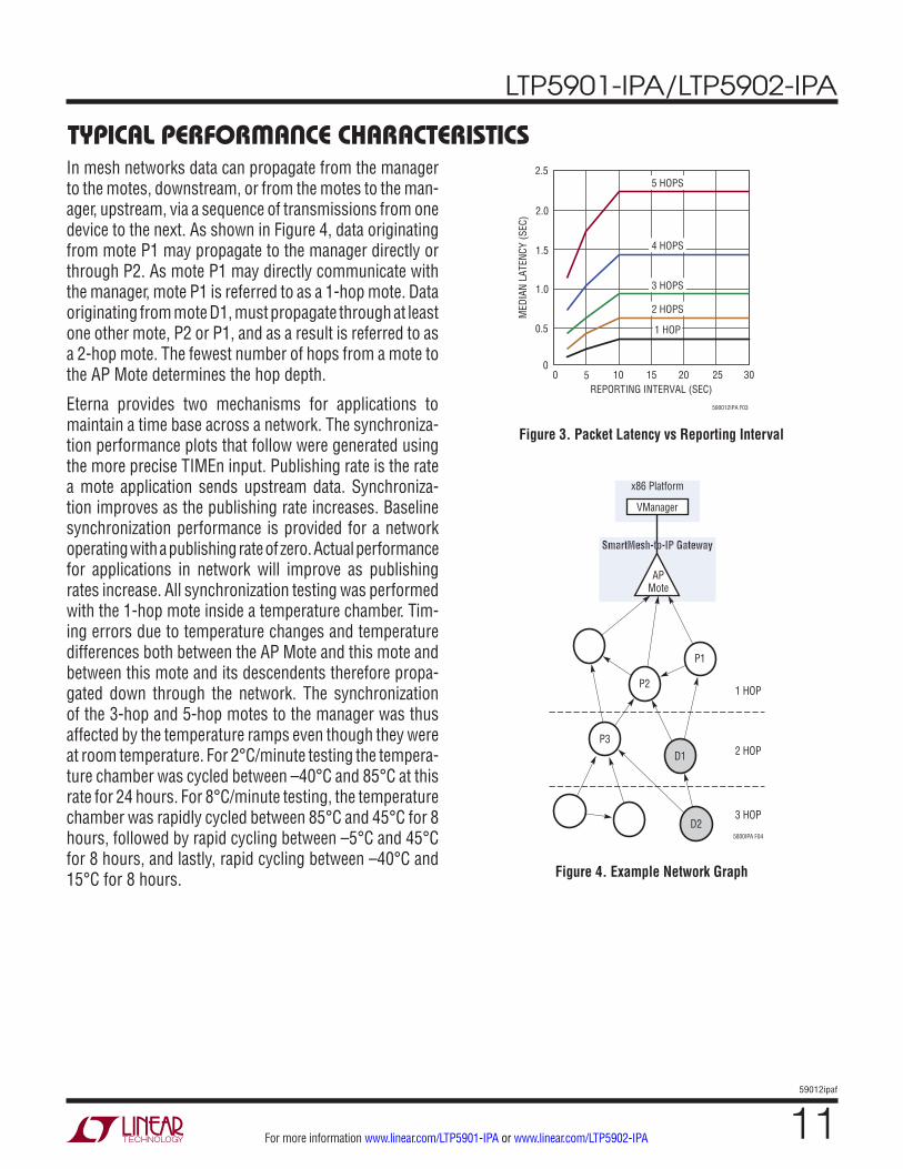
Typical perFormance characTerisTicsIn mesh networks data can propagate from the manager to the motes, downstream, or from the motes to the man-ager, upstream, via a sequence of transmissions from one device to the next. As shown in Figure 4, data originating from mote P1 may propagate to the manager directly or through P2. As mote P1 may directly communicate with the manager, mote P1 is referred to as a 1-hop mote. Data originating from mote D1, must propagate through at least one other mote, P2 or P1, and as a result is referred to as a 2-hop mote. The fewest number of hops from a mote to the AP Mote determines the hop depth.
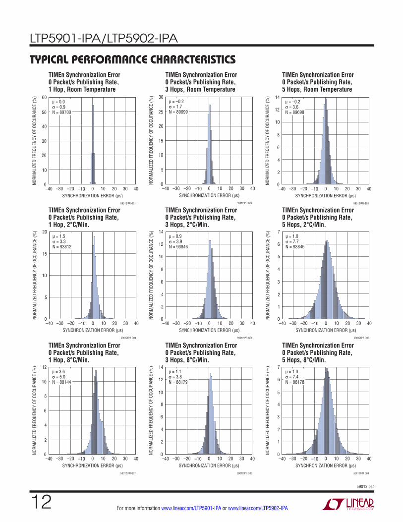
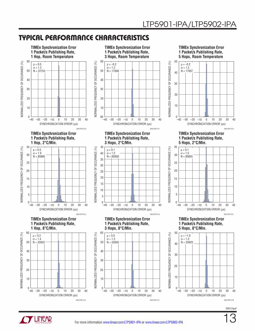
Eterna provides two mechanisms for applications to maintain a time base across a network. The synchroniza-tion performance plots that follow were generated using the more precise TIMEn input. Publishing rate is the rate a mote application sends upstream data. Synchroniza-tion improves as the publishing rate increases. Baseline synchronization performance is provided for a network operating with a publishing rate of zero. Actual performance for applications in network will improve as publishing rates increase. All synchronization testing was performed with the 1-hop mote inside a temperature chamber. Tim-ing errors due to temperature changes and temperature differences both between the AP Mote and this mote and between this mote and its descendents therefore propa-gated down through the network. The synchronization of the 3-hop and 5-hop motes to the manager was thus affected by the temperature ramps even though they were at room temperature. For 2°C/minute testing the tempera-ture chamber was cycled between –40°C and 85°C at this rate for 24 hours. For 8°C/minute testing, the temperature chamber was rapidly cycled between 85°C and 45°C for 8 hours, followed by rapid cycling between –5°C and 45°C for 8 hours, and lastly, rapid cycling between –40°C and 15°C for 8 hours. Figure 4. Example Network Graph
Figure 3. Packet Latency vs Reporting Interval
1 HOP
2 HOP
3 HOP
5800IPA F04
P1
P2
P3D1
D2
APMote
VManager
x86 Platform
SmartMesh-to-IP Gateway
REPORTING INTERVAL (SEC)0
0
MED
IAN
LATE
NCY
(SEC
)
0.5
1.0
1.5
2.0
2.5
5 10 15 20
590012IPA F03
25 30
5 HOPS
4 HOPS
3 HOPS
2 HOPS
1 HOP
LTP5901-IPA/LTP5902-IPA
1259012ipaf
For more information www.linear.com/LTP5901-IPA or www.linear.com/LTP5902-IPA
Typical perFormance characTerisTicsTIMEn Synchronization Error 0 Packet/s Publishing Rate, 1 Hop, Room Temperature
TIMEn Synchronization Error 0 Packet/s Publishing Rate, 1 Hop, 2°C/Min.
TIMEn Synchronization Error 0 Packet/s Publishing Rate, 1 Hop, 8°C/Min.
TIMEn Synchronization Error 0 Packet/s Publishing Rate, 3 Hops, Room Temperature
TIMEn Synchronization Error 0 Packet/s Publishing Rate, 3 Hops, 2°C/Min.
TIMEn Synchronization Error 0 Packet/s Publishing Rate, 3 Hops, 8°C/Min.
TIMEn Synchronization Error 0 Packet/s Publishing Rate, 5 Hops, Room Temperature
TIMEn Synchronization Error 0 Packet/s Publishing Rate, 5 Hops, 2°C/Min.
TIMEn Synchronization Error 0 Packet/s Publishing Rate, 5 Hops, 8°C/Min.
SYNCHRONIZATION ERROR (µs)–40
NORM
ALIZ
ED F
REQU
ENCY
OF
OCCU
RANC
E (%
)
30
40
–10 40
59012IPR G01
20
10
0–30 –20 0 10 20 30
50
60µ = 0.0σ = 0.9N = 89700
SYNCHRONIZATION ERROR (µs)–40
NORM
ALIZ
ED F
REQU
ENCY
OF
OCCU
RANC
E (%
)
15
20
–10 40
59012IPR G02
10
5
0–30 –20 0 10 20 30
25
30µ = –0.2σ = 1.7N = 89699
SYNCHRONIZATION ERROR (µs)–40
NORM
ALIZ
ED F
REQU
ENCY
OF
OCCU
RANC
E (%
)
8
10
–10 40
59012IPR G03
6
4
2
0–30 –20 0 10 20 30
12
14µ = –0.2σ = 3.6N = 89698
SYNCHRONIZATION ERROR (µs)–40
NORM
ALIZ
ED F
REQU
ENCY
OF
OCCU
RANC
E (%
)
10
15
–10 40
59012IPR G04
5
0–30 –20 0 10 20 30
20µ = 1.5σ = 3.3N = 93812
SYNCHRONIZATION ERROR (µs)–40
NORM
ALIZ
ED F
REQU
ENCY
OF
OCCU
RANC
E (%
)
8
10
–10 40
59012IPR G05
6
4
2
0–30 –20 0 10 20 30
12
14µ = 0.9σ = 3.9N = 93846
SYNCHRONIZATION ERROR (µs)–40
NORM
ALIZ
ED F
REQU
ENCY
OF
OCCU
RANC
E (%
)4
5
–10 40
59012IPR G06
3
2
1
0–30 –20 0 10 20 30
6
7µ = 1.0σ = 7.7N = 93845
SYNCHRONIZATION ERROR (µs)–40
NORM
ALIZ
ED F
REQU
ENCY
OF
OCCU
RANC
E (%
)
8
–10 40
59012IPR G07
6
4
2
0–30 –20 0 10 20 30
10
12µ = 3.6σ = 5.0N = 88144
SYNCHRONIZATION ERROR (µs)–40
NORM
ALIZ
ED F
REQU
ENCY
OF
OCCU
RANC
E (%
)
8
–10 40
59012IPR G08
6
4
2
0–30 –20 0 10 20 30
10
14
12
µ = 1.1σ = 3.8N = 88179
SYNCHRONIZATION ERROR (µs)–40
NORM
ALIZ
ED F
REQU
ENCY
OF
OCCU
RANC
E (%
)
4
–10 40
59012IPR G09
3
2
1
0–30 –20 0 10 20 30
5
7
6
µ = 1.0σ = 7.4N = 88178
LTP5901-IPA/LTP5902-IPA
1359012ipaf
For more information www.linear.com/LTP5901-IPA or www.linear.com/LTP5902-IPA
Typical perFormance characTerisTics
SYNCHRONIZATION ERROR (µs)–40
NORM
ALIZ
ED F
REQU
ENCY
OF
OCCU
RANC
E (%
)
40
–10 40
59012IPR G10
30
20
10
0–30 –20 0 10 20 30
50
60µ = 0.0σ = 1.2N = 22753
SYNCHRONIZATION ERROR (µs)–40
NORM
ALIZ
ED F
REQU
ENCY
OF
OCCU
RANC
E (%
)
40
–10 40
59012IPR G11
30
20
10
00–30 –20 0 10 20 30
50
60µ = –0.2σ = 1.2N = 17008
SYNCHRONIZATION ERROR (µs)–40
NORM
ALIZ
ED F
REQU
ENCY
OF
OCCU
RANC
E (%
)
40
–10 40
59012IPR G12
30
20
10
0–30 –20 0 10 20 30
50µ = –0.2σ = 1.2N = 17007
SYNCHRONIZATION ERROR (µs)–40
NORM
ALIZ
ED F
REQU
ENCY
OF
OCCU
RANC
E (%
)
20
25
–10 40
59012IPR G13
15
10
5
0–30 –20 0 10 20 30
30
35µ = 0.5σ = 1.9N = 85860
SYNCHRONIZATION ERROR (µs)–40
NORM
ALIZ
ED F
REQU
ENCY
OF
OCCU
RANC
E (%
)
30
35
–10 40
59012IPR G13
10
5
25
20
15
0–30 –20 0 10 20 30
40
45µ = 0.1σ = 1.5N = 85858
SYNCHRONIZATION ERROR (µs)–40
NORM
ALIZ
ED F
REQU
ENCY
OF
OCCU
RANC
E (%
) 35
–10 40
59012IPR G15
15
10
5
30
25
20
0–30 –20 0 10 20 30
µ = 0.1σ = 1.5N = 85855
SYNCHRONIZATION ERROR (µs)–40
NORM
ALIZ
ED F
REQU
ENCY
OF
OCCU
RANC
E (%
) 60
–10 40
59012IPR G16
20
10
50
40
30
0–30 –20 0 10 20 30
µ = 0.2σ = 1.4N = 33932
SYNCHRONIZATION ERROR (µs)–40
NORM
ALIZ
ED F
REQU
ENCY
OF
OCCU
RANC
E (%
) 60
–10 40
59012IPR G17
20
10
50
40
30
0–30 –20 0 10 20 30
µ = 0.0σ = 1.3N = 33930
SYNCHRONIZATION ERROR (µs)–40
NORM
ALIZ
ED F
REQU
ENCY
OF
OCCU
RANC
E (%
)
–10 40
59012IPR G18
20
10
50
40
30
0–30 –20 0 10 20 30
µ = –1.0σ = 1.3N = 33929
TIMEn Synchronization Error 1 Packet/s Publishing Rate, 1 Hop, Room Temperature
TIMEn Synchronization Error 1 Packet/s Publishing Rate, 1 Hop, 2°C/Min.
TIMEn Synchronization Error 1 Packet/s Publishing Rate, 1 Hop, 8°C/Min.
TIMEn Synchronization Error 1 Packet/s Publishing Rate, 3 Hops, Room Temperature
TIMEn Synchronization Error 1 Packet/s Publishing Rate, 3 Hops, 2°C/Min.
TIMEn Synchronization Error 1 Packet/s Publishing Rate, 3 Hops, 8°C/Min.
TIMEn Synchronization Error 1 Packet/s Publishing Rate, 5 Hops, Room Temperature
TIMEn Synchronization Error 1 Packet/s Publishing Rate, 5 Hops, 2°C/Min.
TIMEn Synchronization Error 1 Packet/s Publishing Rate, 5 Hops, 8°C/Min.
LTP5901-IPA/LTP5902-IPA
1459012ipaf
For more information www.linear.com/LTP5901-IPA or www.linear.com/LTP5902-IPA
pin FuncTions
NO POWER SUPPLY TYPE I/O PULL DESCRIPTION1 GND Power - - Ground Connection11 GND Power - - Ground Connection20 GND Power - - Ground Connection30 GND Power - - Ground Connection34 GND Power - - Ground Connection37 GND Power - - Ground Connection42 GND Power - - Ground Connection56 GND Power - - Ground Connection66 GND Power - - Ground Connection55 VSUPPLY Power - - Power Supply Input to Eterna
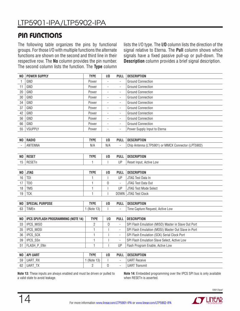
The following table organizes the pins by functional groups. For those I/O with multiple functions the alternate functions are shown on the second and third line in their respective row. The No column provides the pin number. The second column lists the function. The Type column
lists the I/O type. The I/O column lists the direction of the signal relative to Eterna. The Pull column shows which signals have a fixed passive pull-up or pull-down. The Description column provides a brief signal description.
NO RADIO TYPE I/O PULL DESCRIPTION- ANTENNA N/A N/A - Chip Antenna (LTP5901) or MMCX Connector (LPT5902)
NO RESET TYPE I/O PULL DESCRIPTION
15 RESETn 1 I UP Reset Input, Active Low
NO JTAG TYPE I/O PULL DESCRIPTION16 TDI 1 I UP JTAG Test Data In17 TDO 1 O - JTAG Test Data Out18 TMS 1 I UP JTAG Test Mode Select19 TCK 1 I DOWN JTAG Test Clock
NO SPECIAL PURPOSE TYPE I/O PULL DESCRIPTION63 TIMEn 1 (Note 13) I - Time Capture Request, Active Low
NO IPCS SPI/FLASH PROGRAMMING (NOTE 14) TYPE I/O PULL DESCRIPTION33 IPCS_MISO 2 O - SPI Flash Emulation (MISO) Master in Slave Out Port35 IPCS_MOSI 1 I - SPI Flash Emulation (MOSI) Master Out Slave in Port36 IPCS_SCK 1 I - SPI Flash Emulation (SCK) Serial Clock Port39 IPCS_SSn 1 I - SPI Flash Emulation Slave Select, Active Low51 FLASH_P_ENn 1 I UP Flash Program Enable, Active Low
NO API UART TYPE I/O PULL DESCRIPTION59 UART_RX 1 (Note 13) I - UART Receive62 UART_TX 2 O - UART Transmit
Note 13: These inputs are always enabled and must be driven or pulled to a valid state to avoid leakage.
Note 14: Embedded programming over the IPCS SPI bus is only available when RESETn is asserted.
LTP5901-IPA/LTP5902-IPA
1559012ipaf
For more information www.linear.com/LTP5901-IPA or www.linear.com/LTP5902-IPA
pin FuncTionsVSUPPLY: System and I/O Power Supply. Provides power to the module. The digital-interface I/O voltages are also set by this voltage.
ANTENNA: Multiplexed Receiver Input and Transmitter Output Pin. The impedance presented to the MMCX con-nector should be 50Ω, single-ended with respect to ground.
RESETn: The asynchronous reset signal is internally pulled up. Resetting Eterna will result in the ARM Cortex-M3 rebooting and loss of network connectivity. Use of this signal for resetting Eterna is not recommended, except during power-on and in-circuit programming.
TMS, TCK, TDI, TDO: JTAG port supporting software debug and boundary scan.
UART_RX, UART_TX: The HDLC coded API UART inter-face provided the primary mechanism for communication between the SmartMesh-to-IP Gateway CPU and the LTP5901/2.
TIMEn: The rising edge of a Pulse Per Second (PPS) signal at the TIMEn input provides the AP Mote with the network timing reference. The use of a PPS input is optional - see the Access Point section of the SmartMesh IP User’s Guide for details.
UARTC0_RX, UARTC0_TX: The CLI UART provides a mechanism for monitoring, configuration and control of Eterna during operation.
FLASH_P_ENn, IPCS_SSn, IPCS_SCK, IPCS_MISO, IPCS_SSn: The In-circuit programming control system (IPCS) bus enables in-circuit programming of Eterna’s flash memory. IPCS_SCK is a clock and should be terminated appropriately for the driving source to prevent overshoot and ringing.
LTP5901-IPA/LTP5902-IPA
1659012ipaf
For more information www.linear.com/LTP5901-IPA or www.linear.com/LTP5902-IPA
NETWORK MANAGEMENT OPTIONS
SmartMesh IP managers provide dynamic network optimi-zation, deterministic power management, intelligent rout-ing, and configurable bandwidth allocation while achieving carrier class data reliability and low power operation. Linear Technology offers two solutions to manage SmartMesh IP Networks: Embedded Manager products such as the LTP5902-IPR and VManager, a software solution, which operates in tandem with one or more Access Point Motes, such as the LTP5902-IPA. For a complete description of VManager please refer to the SmartMesh IP User’s Guide.
VMANAGER + AP MOTE BENEFITS
While the SmartMesh IP Embedded Manager form factor provides convenience for many applications, it has some limitations due to resource constraints associated with a SoC. The VManager resolves many of the limitations of a single chip solution by moving the management function to a more powerful computing platform. With the “manager” running on a range of x86 hardware platforms in a Virtual Machine, customers have the flexibility to select from a broad range of existing third party hardware, while the VManager software has the resources needed to scale. The feature highlights of this larger scale manager are as follows:n 100% compatible with all SmartMesh IP Motesn Increased Management capability
n Network scale to thousands of motesn Network throughput scales at 40 pkt/sec per AP Mote
upstream - more than 12x the embedded manager n Downstream throughput scales up to 17 pkt/sec per
AP - up to 96x the embedded managern AP Mote and management function hot redundancy
n Optional GPS Integrationn Locking of network time to real timen Support of discontinuous network segments in a
single network n Shared sense of time across all network segments
operaTionAP MOTE / VMANAGER COMMUNICATION
VManager may be connected to an AP Mote over a TCP/IP socket or directly over a COM port. COM ports may be implemented as:n Embedded UART(s) operating at LVTTL switching
thresholdsn UART(s) over USBn RS-485
A SmartMesh-to-IP Gateway typically provides the con-nection between the AP Mote the VManager via a TCP/IP Socket. The corresponding TCP/IP network can take many forms, including:n Ethernetn WiFin Cellularn DSLn Cable Modem
For detailed information on AP Mote implementation see the SmartMesh IP User’s Guide.
AP MOTE TIME SYNCHRONIzATION
The SmartMesh IP network protocol establishes network wide timing synchronization of all wireless devices. To accomplish this, each network must have a single time base. The LTP5901/2-IPA supports operating from an internal time base, network time base or an external time base. See the Access Points section of the SmartMesh IP User’s Guide for the engineering trade-offs with respect to AP Mote time base options.
LTP5901-IPA/LTP5902-IPA
1759012ipaf
For more information www.linear.com/LTP5901-IPA or www.linear.com/LTP5902-IPA
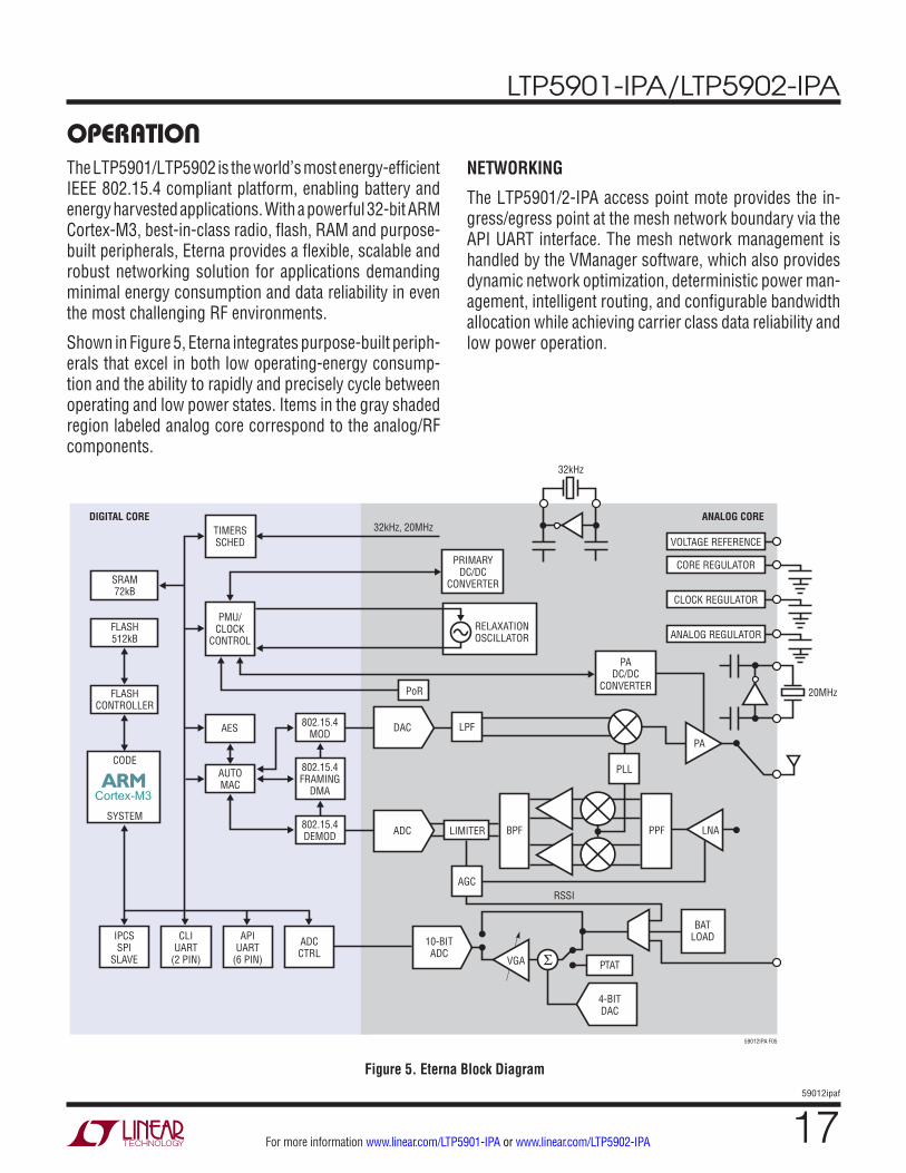
The LTP5901/LTP5902 is the world’s most energy-efficient IEEE 802.15.4 compliant platform, enabling battery and energy harvested applications. With a powerful 32-bit ARM Cortex-M3, best-in-class radio, flash, RAM and purpose-built peripherals, Eterna provides a flexible, scalable and robust networking solution for applications demanding minimal energy consumption and data reliability in even the most challenging RF environments.
Shown in Figure 5, Eterna integrates purpose-built periph-erals that excel in both low operating-energy consump-tion and the ability to rapidly and precisely cycle between operating and low power states. Items in the gray shaded region labeled analog core correspond to the analog/RF components.
NETWORKING
The LTP5901/2-IPA access point mote provides the in-gress/egress point at the mesh network boundary via the API UART interface. The mesh network management is handled by the VManager software, which also provides dynamic network optimization, deterministic power man-agement, intelligent routing, and configurable bandwidth allocation while achieving carrier class data reliability and low power operation.
Figure 5. Eterna Block Diagram
4-BITDAC
VGA
BPF PPF
AGC
LPF
ADC
DAC
10-BITADC
PLL
RSSI
LNA
PA
20MHz
32kHz
32kHz, 20MHz
PTAT
59012IPA F05
BATLOAD
LIMITER
VOLTAGE REFERENCE
ANALOG COREDIGITAL CORE
CORE REGULATOR
CLOCK REGULATOR
ANALOG REGULATOR
PADC/DC
CONVERTER
PRIMARYDC/DC
CONVERTER
RELAXATIONOSCILLATOR
PoR
TIMERSSCHED
SRAM72kB
FLASH512kB
FLASHCONTROLLER
CODE
AES
AUTOMAC
802.15.4MOD
802.15.4FRAMING
DMA
IPCSSPI
SLAVE
CLIUART
(2 PIN)
APIUART
(6 PIN)
ADCCTRL
802.15.4DEMOD
SYSTEM
PMU/CLOCK
CONTROL
operaTion

LTP5901-IPA/LTP5902-IPA
1859012ipaf
For more information www.linear.com/LTP5901-IPA or www.linear.com/LTP5902-IPA
operaTionCONFIGURABLE BANDWIDTH ALLOCATION
SmartMesh networks provide configurations that en-able users to make bandwidth and latency versus power trade-offs both network wide and on a per device basis. This flexibility enables solutions to be tailored to the ap-plication requirements, such as request/response, fast file transfer, and alerting. Relevant configuration parameters are described in the SmartMesh IP User’s Guide. The De-sign trade-offs between network performance and current consumption are illustrated via the SmartMesh Power and Performance Estimator.
POWER SUPPLY
Eterna is powered from a single pin, VSUPPLY, which powers the I/O cells and is also used to generate internal supplies. Eterna’s two on-chip DC/DC converters minimize Eterna’s energy consumption while the device is awake. To conserve power the DC/DC converters are disabled when the device is in low power state. Eterna’s integrated power supply conditioning architecture, including the two inte-grated DC/DC converters and three integrated low dropout regulators, provides excellent rejection of supply noise. Eterna’s operating supply voltage range is high enough to support direct connection to lithium-thionyl chloride, Li-SOCl2, sources and wide enough to support battery operation over a broad temperature range.
SUPPLY MONITORING AND RESET
Eterna integrates a power-on-reset (PoR) circuit. As the RESETn input pin is nominally configured with an internal pull-up resistor, no connection is required. Eterna includes a soft brown-out monitor that fully protects the flash from corruption in the event that power is removed while writing to flash. The integrated flash supervisory functionality, in conjunction with a fault tolerant file system, yields a robust nonvolatile storage solution.
PRECISION TIMING
A major feature of Eterna over competing 802.15.4 prod-uct offerings is its low power dedicated timing hardware and timing algorithms. This functionality provides timing
precision two to three orders of magnitude better than any other low power solution available at the time of publication. Improved timing accuracy allows motes to minimize the amount of radio listening time required to ensure packet reception thereby lowering even further the power consumed by SmartMesh networks. Eterna’s patented timing hardware and timing algorithms provide superior performance over rapid temperature changes, further differentiating Eterna’s reliability when compared with other wireless products. In addition, precise timing enables networks to reduce spectral dead time, increasing total network throughput.
TIME REFERENCES
Eterna includes three clock sources: an internal relaxation oscillator, a low power oscillator designed for a 32.768kHz crystal, and the radio reference oscillator designed for a 20MHz crystal.
Relaxation Oscillator
The relaxation oscillator is the primary clock source for Eterna, providing the clock for the CPU, memory subsys-tems, and all peripherals. The internal relaxation oscillator is dynamically calibrated to 14.3728MHz.
32.768kHz Crystal
Once Eterna is powered up and the 32.768kHz crystal source has begun oscillating, the 32.768kHz crystal remains operational and is used as the timing basis. See the State Diagram section, for a description of Eterna’s operational states.
20MHz Crystal
The 20MHz crystal source provides a frequency reference for the radio, and is automatically enabled and disabled by Eterna as needed.
RADIO
Eterna includes the lowest power commercially available 2.4GHz IEEE 802.15.4e radio by a substantial margin. (Please refer to section Radio Specifications, for power con-sumption numbers). Eterna’s integrated power amplifier
LTP5901-IPA/LTP5902-IPA
1959012ipaf
For more information www.linear.com/LTP5901-IPA or www.linear.com/LTP5902-IPA
operaTionis calibrated and temperature-compensated to consistently provide power at a limit suitable for worldwide radio certifications. Additionally, Eterna uniquely includes a hardware-based autonomous MAC that handles precise sequencing of peripherals, including the transmitter, the receiver, and advanced encryption standard (AES) periph-erals. The hardware-based autonomous media access controller (MAC) minimizes CPU activity, thereby further decreasing power consumption.
UARTS
The principal network interface is through the application programming interface (API) UART. A command-line inter-face (CLI) UART is also provided for support of test and debug functions. Both UARTs sense activity continuously, consuming virtually no power until data is transferred over the port and then automatically returning to their lowest power state after the conclusion of a transfer. The defini-tion for packet encoding on the API UART interface can be found in the SmartMesh IP User’s Guide.
API UART PROTOCOL
Unlike the LTP5901/2-IPM or the LTP5901/2-IPR the LTP5901/2-IPA operates its API UART interface without flow control, requiring only the UART_TX and UART_RX signals. The API UART is configured at 961.6 kbaud, one stop bit and no parity.
CLI UART
The command line interface (CLI) UART port is a two wire protocol (TX and RX) that operates at a fixed 9600 baud rate with one stop bit and no parity. The CLI UART interface is intended to support command line instructions and response activity.
SECURITY
Network security is an often overlooked component of a complete network solution. Proper implementation of se-curity protocols is significant in terms of both engineering effort and market value in an OEM product. SmartMesh IP system solutions provide a FIPS-197 validated encryption scheme that includes authentication and encryption at the MAC and network layers with separate keys for each mote. This not only yields end-to-end security, but if a mote is somehow compromised, communication from other motes is still secure. A mechanism for secure key exchange al-lows for key rotation. To prevent physical attacks, Eterna includes hardware support for electronically locking de-vices, thereby preventing access to Eterna’s flash and RAM memory and thus the keys and code stored therein.
SOFTWARE INSTALLATION
Devices are supplied with the flash erased, requiring pro-gramming as part of the OEMs manufacturing procedure. The US Department of Commerce places restrictions on export of systems and software supporting encryption. All of Linear/Dust product software produced to date contains encryption and is subject to export regulations and may be provided only via MyLinear, www.linear.com/mylinear. Customers purchasing SmartMesh products will receive a certificate containing a registration key and registration instructions with their order. After registering with the key, customers will be able to download SmartMesh software images from MyLinear. Once registered, customers will receive automated e-mail notifications as software updates are made avaialbe.
Linear Technology offers the DC9010, in circuit program-mer for the Eterna based products. While the DC9010, is provided as a finished product, the design documents are provided as a reference for customers.
Once software has been loaded, devices can be configured via either the CLI or API ports. Configuration commands and settings are defined in the SmartMesh IP User’s Guide and the SmartMesh IP VManager CLI Guide.
LTP5901-IPA/LTP5902-IPA
2059012ipaf
For more information www.linear.com/LTP5901-IPA or www.linear.com/LTP5902-IPA
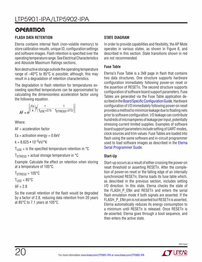
operaTionFLASH DATA RETENTION
Eterna contains internal flash (non-volatile memory) to store calibration results, unique ID, configuration settings and software images. Flash retention is specified over the operating temperature range. See Electrical Characteristics and Absolute Maximum Ratings sections.
Non destructive storage outside the operating temperature range of –40°C to 85°C is possible; although, this may result in a degradation of retention characteristics.
The degradation in flash retention for temperatures ex-ceeding specified temperatures can be approximated by calculating the dimensionless acceleration factor using the following equation.
AF = e
Eak
⎛
⎝⎜
⎞
⎠⎟•
1TUSE+273
−1
TSTRESS+273
⎛
⎝⎜
⎞
⎠⎟
⎡
⎣⎢
⎤
⎦⎥
Where:
AF = acceleration factor
Ea = activation energy = 0.6eV
k = 8.625 • 10–5eV/°K
TUSE = is the specified temperature retention in °C
TSTRESS = actual storage temperature in °C
Example: Calculate the effect on retention when storing at a temperature of 105°C.
TSTRESS = 105°C
TUSE = 85°C
AF = 2.8
So the overall retention of the flash would be degraded by a factor of 2.8, reducing data retention from 20 years at 85°C to 7.1 years at 105°C.
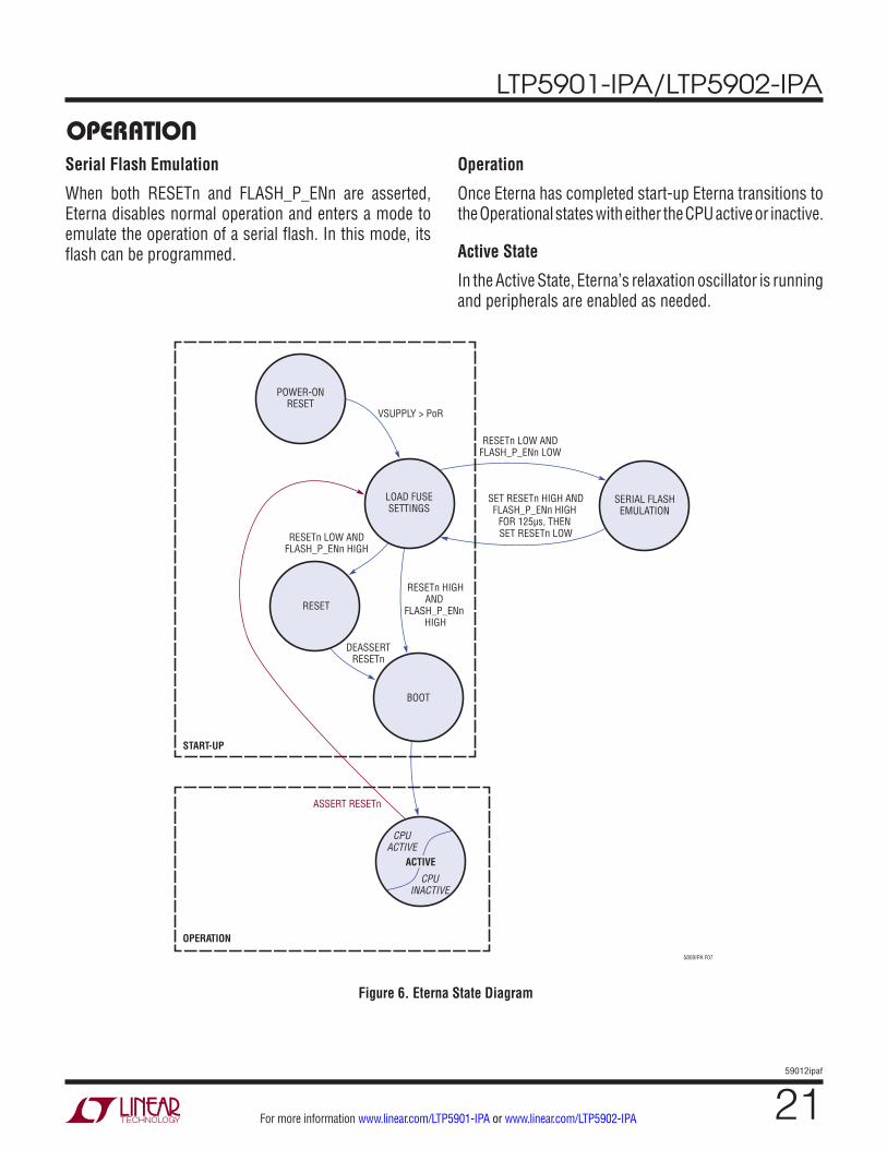
STATE DIAGRAM
In order to provide capabilities and flexibility, the AP Mote operates in various states, as shown in Figure 6, and described in this section. State transitions shown in red are not recommended.
Fuse Table
Eterna’s Fuse Table is a 2kB page in flash that contains two data structures. One structure supports hardware configuration immediately following power-on reset or the assertion of RESETn. The second structure supports configuration of software board support parameters. Fuse Tables are generated via the Fuse Table application de-scribed in the Board Specific Configuration Guide. Hardware configuration of I/O immediately following power-on reset provides a method to minimize leakage due to floating nets prior to software configuration. I/O leakage can contribute hundreds of microamperes of leakage per input, potentially stressing current limited supplies. Examples of software board support parameters include setting of UART modes, clock sources and trim values. Fuse Tables are loaded into flash using the same software and in-circuit programmer used to load software images as described in the Eterna Serial Programmer Guide.
Start-Up
Start-up occurs as a result of either crossing the power-on reset threshold or asserting RESETn. After the comple-tion of power-on reset or the falling edge of an internally synchronized RESETn, Eterna loads its fuse table which, as described in the previous section, includes setting I/O direction. In this state, Eterna checks the state of the FLASH_P_ENn and RESETn and enters the serial flash emulation mode if both signals are asserted. If the FLASH_P_ENn pin is not asserted but RESETn is asserted, Eterna automatically reduces its energy consumption to a minimum until RESETn is released. Once RESETn is de-asserted, Eterna goes through a boot sequence, and then enters the active state.
LTP5901-IPA/LTP5902-IPA
2159012ipaf
For more information www.linear.com/LTP5901-IPA or www.linear.com/LTP5902-IPA
Serial Flash Emulation
When both RESETn and FLASH_P_ENn are asserted, Eterna disables normal operation and enters a mode to emulate the operation of a serial flash. In this mode, its flash can be programmed.
Operation
Once Eterna has completed start-up Eterna transitions to the Operational states with either the CPU active or inactive.
Active State
In the Active State, Eterna’s relaxation oscillator is running and peripherals are enabled as needed.
operaTion
Figure 6. Eterna State Diagram
SERIAL FLASHEMULATION
LOAD FUSESETTINGS
RESETn LOW ANDFLASH_P_ENn HIGH
RESETn HIGHAND
FLASH_P_ENn HIGH
RESET
DEASSERTRESETn
BOOT
START-UP
OPERATION
5800IPA F07
ASSERT RESETn
CPUACTIVE
CPUINACTIVE
POWER-ONRESET
RESETn LOW ANDFLASH_P_ENn LOW
SET RESETn HIGH ANDFLASH_P_ENn HIGH
FOR 125µs, THEN SET RESETn LOW
VSUPPLY > PoR
ACTIVE
LTP5901-IPA/LTP5902-IPA
2259012ipaf
For more information www.linear.com/LTP5901-IPA or www.linear.com/LTP5902-IPA
applicaTions inFormaTionREGULATORY AND STANDARDS COMPLIANCE
Radio Certification
The LTP5901 and LTP5902 have been certified under a single modular certification, with the module name of ETERNA2. Following the regulatory requirements provided in the ETERNA2 Users Guide can enable customers to ship products in the supported geographies, by simply completing an unintentional radiator scan of the finished product(s). The ETERNA2 Users Guide also provides the technical information needed to enable customers to fur-ther certify either the modules or products based upon the modules in geographies that have not or do not support modular certification.
Compliance to Restriction of Hazardous Substances (RoHS)
Restriction of hazardous substances 2 (RoHS 2) is a directive that places maximum concentration limits on the use of certain hazardous substances in electrical and electronic equipment. Linear Technology is committed to meeting the requirements of the European Community directive 2011/65/EU.
This product has been specifically designed to utilize RoHS-compliant materials and to eliminate or reduce the use of restricted materials to comply with 2011/65/EU.
The RoHS-compliant design features include:
• RoHS-compliant solder for solder joints
• RoHS-compliant base metal alloys
• RoHS-compliant precious metal plating
• RoHS-compliant cable assemblies and connector choices
• Halogen-free mold compound
• RoHS-compliant and 245°C re-flow compatible
Note: Customers may elect to use certain types of lead-free solder alloys in accordance with the European Com-munity directive 2011/65/EU. Depending on the type of solder paste chosen, a corresponding process change to optimize reflow temperatures may be required.
SOLDERING INFORMATION
The LTP5901 and LTP5902 are suitable for both eutectic PbSn and RoHS-6 reflow. The maximum reflow solder-ing temperature is 260°C. A more detailed description of layout recommendations, assembly procedures and design considerations is included in the LTP5901 and LTP5902 Hardware Integration Guide.
LTP5901-IPA/LTP5902-IPA
2359012ipaf
For more information www.linear.com/LTP5901-IPA or www.linear.com/LTP5902-IPA
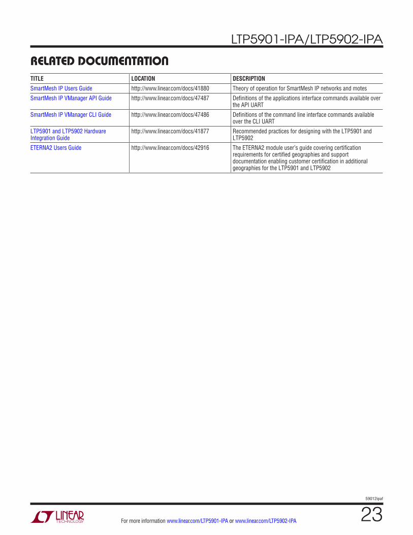
relaTeD DocumenTaTionTITLE LOCATION DESCRIPTION
SmartMesh IP Users Guide http://www.linear.com/docs/41880 Theory of operation for SmartMesh IP networks and motes
SmartMesh IP VManager API Guide http://www.linear.com/docs/47487 Definitions of the applications interface commands available over the API UART
SmartMesh IP VManager CLI Guide http://www.linear.com/docs/47486 Definitions of the command line interface commands available over the CLI UART
LTP5901 and LTP5902 Hardware Integration Guide
http://www.linear.com/docs/41877 Recommended practices for designing with the LTP5901 and LTP5902
ETERNA2 Users Guide http://www.linear.com/docs/42916 The ETERNA2 module user’s guide covering certification requirements for certified geographies and support documentation enabling customer certification in additional geographies for the LTP5901 and LTP5902
LTP5901-IPA/LTP5902-IPA
2459012ipaf
For more information www.linear.com/LTP5901-IPA or www.linear.com/LTP5902-IPA
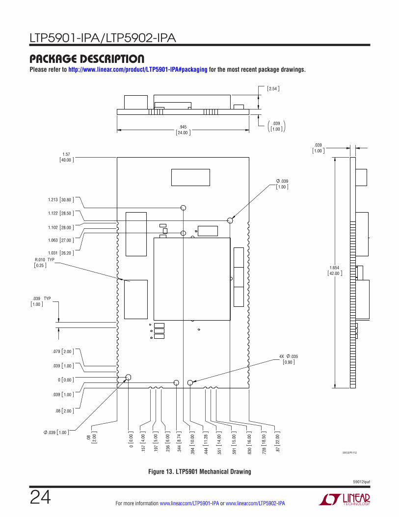
package DescripTionPlease refer to http://www.linear.com/product/LTP5901-IPA#packaging for the most recent package drawings.
Figure 13. LTP5901 Mechanical Drawing
R.0100.25
TYP
.0391.00
TYP
.0391.00
4X .0350.90
.039 1.00
00.
00.08
2.00
.157
4.00
.197
5.00
.236
6.00
.344
8.74
.444
11.2
8
.551
14.0
0
.591
15.0
0
.630
16.0
0
.87
22.0
0
.728
18.5
0
.394
10.0
0
0 0.00
.08 2.00
.039 1.00
.039 1.00
.079 2.00
1.102 28.00
1.063 27.00
1.031 26.20
1.122 28.50
1.213 30.80
1.5740.00
.0391.00
1.65442.00
.1002.54
.0391.00
.945
24.00
59012IPR F12
LTP5901-IPA/LTP5902-IPA
2559012ipaf
For more information www.linear.com/LTP5901-IPA or www.linear.com/LTP5902-IPA
Information furnished by Linear Technology Corporation is believed to be accurate and reliable. However, no responsibility is assumed for its use. Linear Technology Corporation makes no representa-tion that the interconnection of its circuits as described herein will not infringe on existing patent rights.
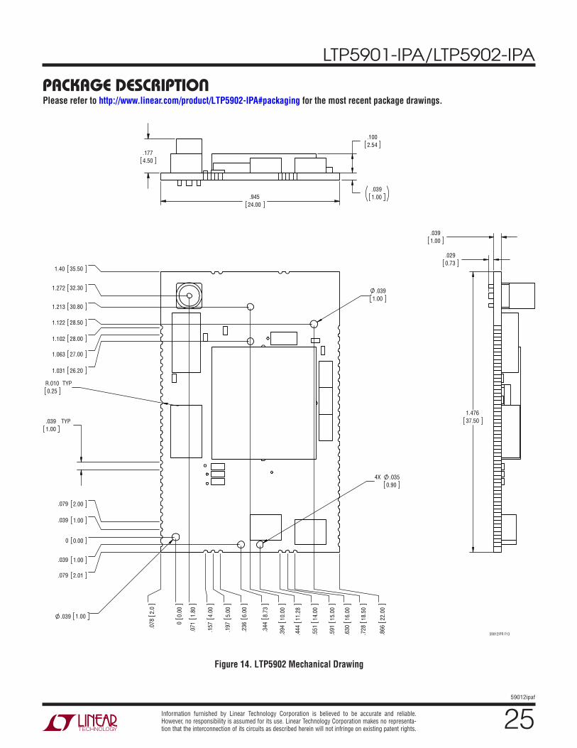
package DescripTionPlease refer to http://www.linear.com/product/LTP5902-IPA#packaging for the most recent package drawings.
Figure 14. LTP5902 Mechanical Drawing
.0391.00
TYP
R.0100.25
TYP
.0391.00
.039 1.00
4X .0350.90
00.
00
.0
782.
0
.1
574.
00
.1
975.
00
.2
366.
00
.3
448.
73
.4
4411
.28
.8
6622
.00
.3
9410
.00
0 0.00
.079 2.01
.039 1.00
.039 1.00
.079 2.00
1.031 26.20
1.213 30.80
1.40 35.50
1.122 28.50
1.102 28.00
1.272 32.30
1.063 27.00
.0
711.
80
.7
2818
.50
.5
5114
.00
.5
9115
.00
.6
3016
.00
1.47637.50
.0391.00
.0290.73
.1002.54
.0391.00
.1774.50
.94524.00
59012IPR F13
LTP5901-IPA/LTP5902-IPA
2659012ipaf
For more information www.linear.com/LTP5901-IPA or www.linear.com/LTP5902-IPA LINEAR TECHNOLOGY CORPORATION 2016
LT 0916 • PRINTED IN USALinear Technology Corporation1630 McCarthy Blvd., Milpitas, CA 95035-7417(408) 432-1900 ● FAX: (408) 434-0507 ● www.linear.com/LTP5901-IPR
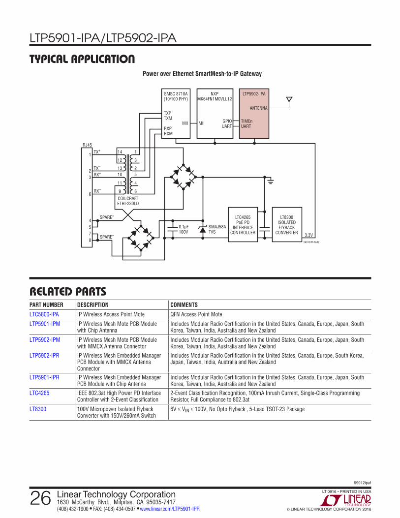
Power over Ethernet SmartMesh-to-IP Gateway
relaTeD parTs
Typical applicaTion
PART NUMBER DESCRIPTION COMMENTS
LTC5800-IPA IP Wireless Access Point Mote QFN Access Point Mote
LTP5901-IPM IP Wireless Mesh Mote PCB Module with Chip Antenna
Includes Modular Radio Certification in the United States, Canada, Europe, Japan, South Korea, Taiwan, India, Australia and New Zealand
LTP5902-IPM IP Wireless Mesh Mote PCB Module with MMCX Antenna Connector
Includes Modular Radio Certification in the United States, Canada, Europe, Japan, South Korea, Taiwan, India, Australia and New Zealand
LTP5902-IPR IP Wireless Mesh Embedded Manager PCB Module with MMCX Antenna Connector
Includes Modular Radio Certification in the United States, Canada, Europe, South Korea, Japan, Taiwan, India, Australia and New Zealand
LTP5901-IPR IP Wireless Mesh Embedded Manager PCB Module with Chip Antenna
Includes Modular Radio Certification in the United States, Canada, Europe, Japan, South Korea, Taiwan, India, Australia and New Zealand
LTC4265 IEEE 802.3at High Power PD Interface Controller with 2-Event Classification
2-Event Classification Recognition, 100mA Inrush Current, Single-Class Programming Resistor, Full Compliance to 802.3at
LT8300 100V Micropower Isolated Flyback Converter with 150V/260mA Switch
6V ≤ VIN ≤ 100V, No Opto Flyback , 5-Lead TSOT-23 Package
14
MII
ANTENNA
MII
TX+
TXPTXM
RXPRXM
GPIOUART
TIMEnUART
0.1µF100V
SMAJ58ATVS
3.3V59012IPA TA02
RJ45
SMSC 8710A(10/100 PHY)
TX–
RX+
RX–
SPARE+
SPARE–
12
1310
1
3
2
11
COILCRAFTETHI-230LD
9
4
6
5
1
23
6
4578
NXPMK64FN1M0VLL12
LTP5902-IPA
LTC4265PoE PD
INTERFACECONTROLLER
LT8300ISOLATEDFLYBACK
CONVERTER