lte interferencescte-sandiego.org/uploads/3/5/4/0/35405245/lte_-_ingress_-_egress... · 1 scte lte...
TRANSCRIPT
1 SCTE LTE Presentation 20140331© 2014 PCT International, Inc. All Rights Reserved.
The New ChallengePresented To
San Diego Chapter SCTEby
Doug MacLeodPCT International
LTE Interference
2 SCTE LTE Presentation 20140331© 2014 PCT International, Inc. All Rights Reserved.

3 SCTE LTE Presentation 20140331© 2014 PCT International, Inc. All Rights Reserved.
Signal egress and ingress has been a major concern in the cable industry since the late ‘70s
Much work has been done to control this issue
A relatively new ingress and egress concern is 4G/LTE cellular telephone service

4 SCTE LTE Presentation 20140331© 2014 PCT International, Inc. All Rights Reserved.
Older Cellphone Technologies
2G and 3G • Mostly for voice – data was an add on
• Less complex modulation –simply more robust
• Takes a beating and you can still talk
• Doesn’t use the same frequencies used by most cable systems
Common name Uplink DownlinkGSM/CDMA/WCDMA850 869-894 MHz 824-849 MHz
GSM900 880-915 MHz 925-960 MHz
GSM1800 1710-1785 MHz 1805-1880 MHz
GSM/CDMA1900 1850-1910 MHz 1930-1990 MHz
WCDMA2100 (AWS) 1710-1755 MHz 2110-2170 MHz
LTE (Long-Term Evolution)
5 SCTE LTE Presentation 20140331© 2014 PCT International, Inc. All Rights Reserved.
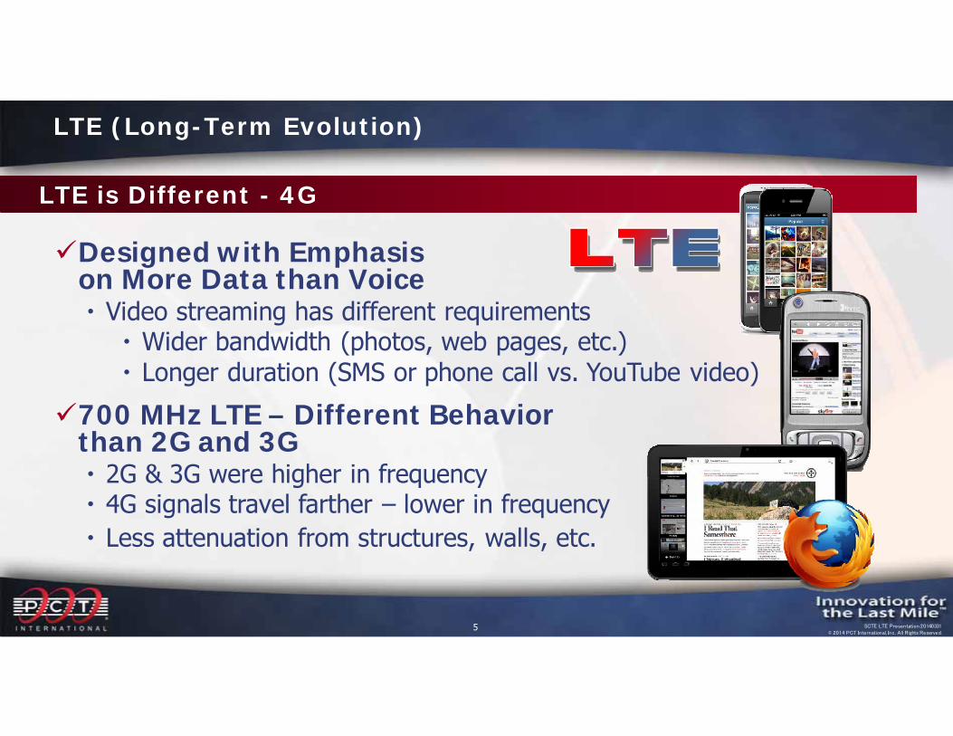
LTE is Different - 4G
Designed with Emphasison More Data than Voice Video streaming has different requirements
Wider bandwidth (photos, web pages, etc.) Longer duration (SMS or phone call vs. YouTube video)
700 MHz LTE – Different Behavior than 2G and 3G 2G & 3G were higher in frequency 4G signals travel farther – lower in frequency Less attenuation from structures, walls, etc.
LTE (Long-Term Evolution)
6 SCTE LTE Presentation 20140331© 2014 PCT International, Inc. All Rights Reserved.
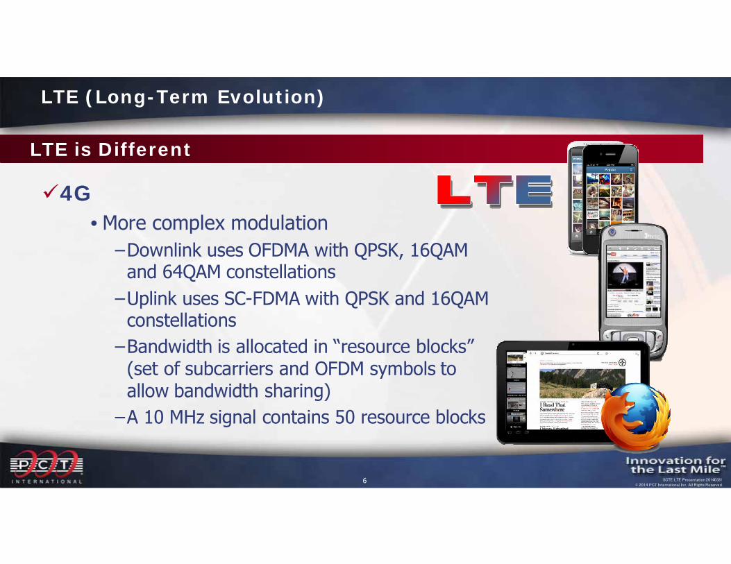
LTE is Different
4G• More complex modulation‒Downlink uses OFDMA with QPSK, 16QAM
and 64QAM constellations‒Uplink uses SC-FDMA with QPSK and 16QAM
constellations‒Bandwidth is allocated in “resource blocks”
(set of subcarriers and OFDM symbols to allow bandwidth sharing)‒A 10 MHz signal contains 50 resource blocks
LTE (Long-Term Evolution)
7 SCTE LTE Presentation 20140331© 2014 PCT International, Inc. All Rights Reserved.
LTE is Different
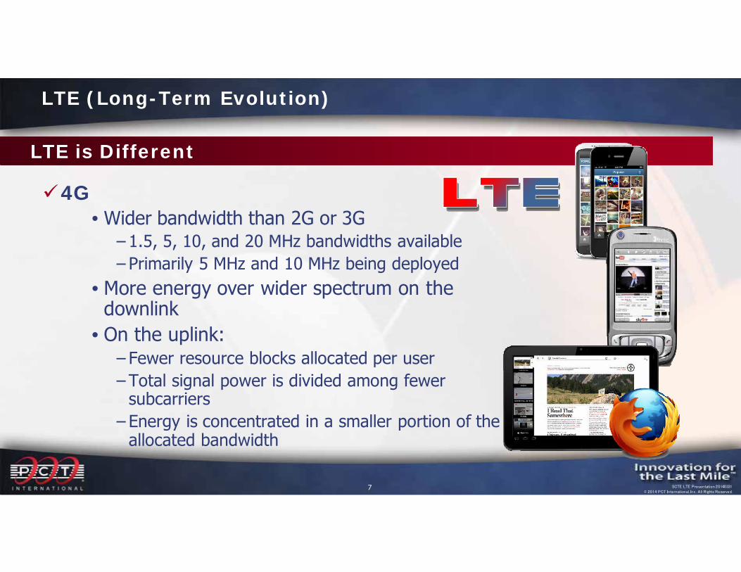
4G• Wider bandwidth than 2G or 3G
‒ 1.5, 5, 10, and 20 MHz bandwidths available‒ Primarily 5 MHz and 10 MHz being deployed
• More energy over wider spectrum on the downlink
• On the uplink:‒ Fewer resource blocks allocated per user‒ Total signal power is divided among fewer
subcarriers‒ Energy is concentrated in a smaller portion of the
allocated bandwidth
LTE (Long-Term Evolution)
8 SCTE LTE Presentation 20140331© 2014 PCT International, Inc. All Rights Reserved.
LTE (Long-Term Evolution)
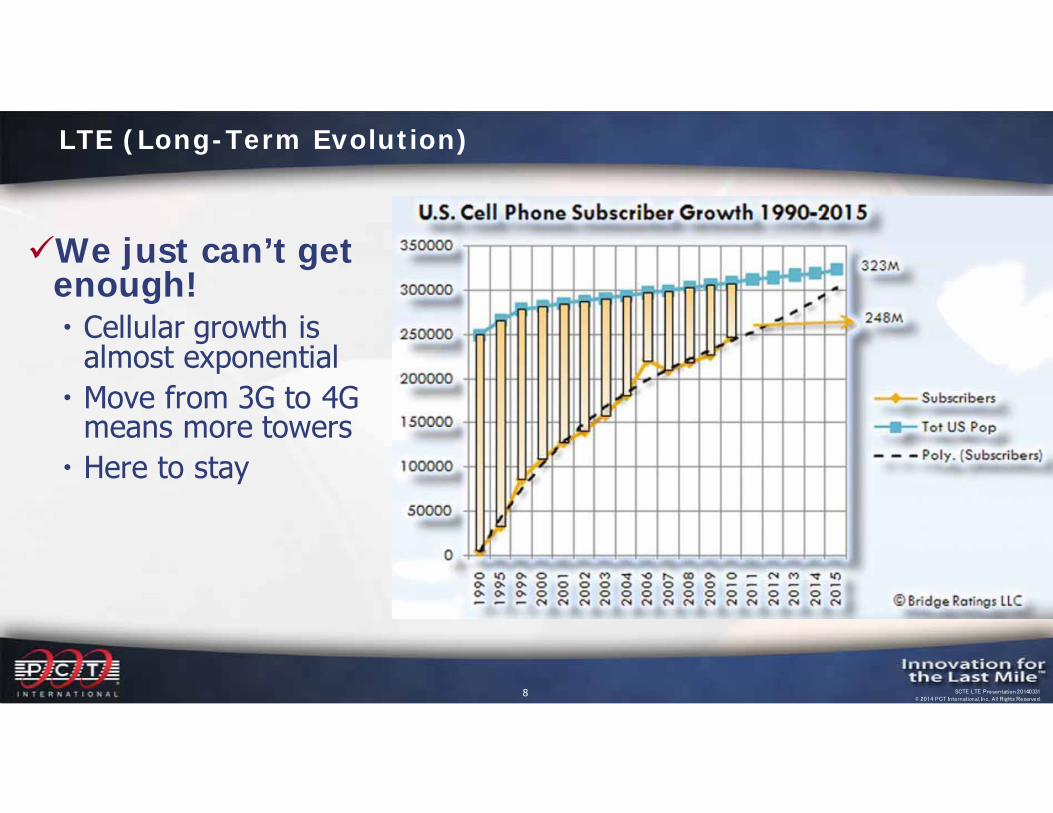
We just can’t get enough! Cellular growth is
almost exponential Move from 3G to 4G
means more towers Here to stay
9 SCTE LTE Presentation 20140331© 2014 PCT International, Inc. All Rights Reserved.
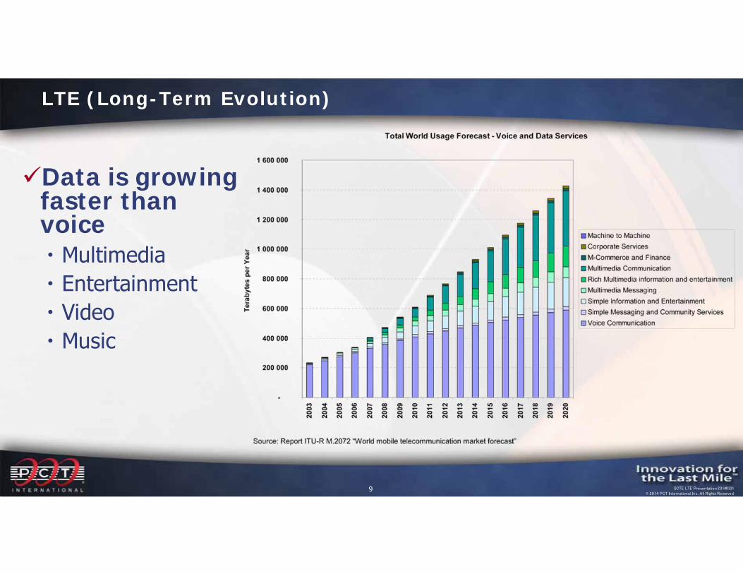
Data is growing faster than voice Multimedia Entertainment Video Music
LTE (Long-Term Evolution)
10 SCTE LTE Presentation 20140331© 2014 PCT International, Inc. All Rights Reserved.
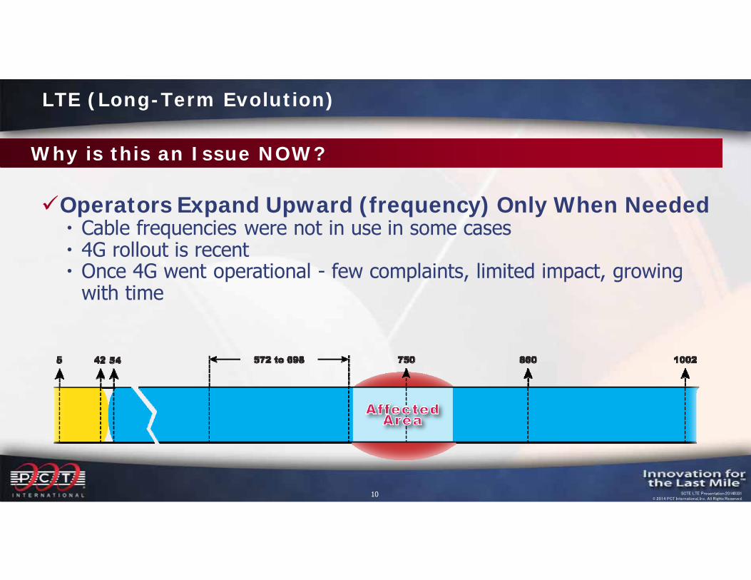
Operators Expand Upward (frequency) Only When Needed Cable frequencies were not in use in some cases 4G rollout is recent Once 4G went operational - few complaints, limited impact, growing
with time
Why is this an Issue NOW?
LTE (Long-Term Evolution)
11 SCTE LTE Presentation 20140331© 2014 PCT International, Inc. All Rights Reserved.
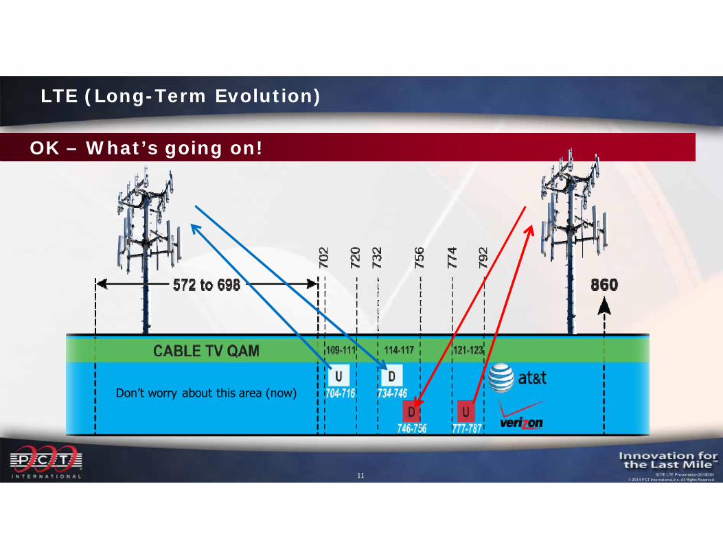
OK – What’s going on!
LTE (Long-Term Evolution)
Don’t worry about this area (now)
12 SCTE LTE Presentation 20140331© 2014 PCT International, Inc. All Rights Reserved.
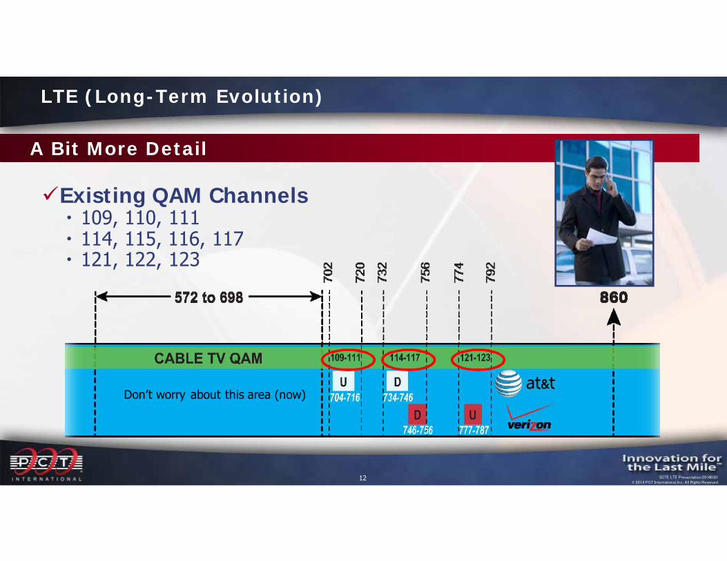
Existing QAM Channels 109, 110, 111 114, 115, 116, 117 121, 122, 123
Don’t worry about this area (now)
A Bit More Detail
LTE (Long-Term Evolution)
13 SCTE LTE Presentation 20140331© 2014 PCT International, Inc. All Rights Reserved.
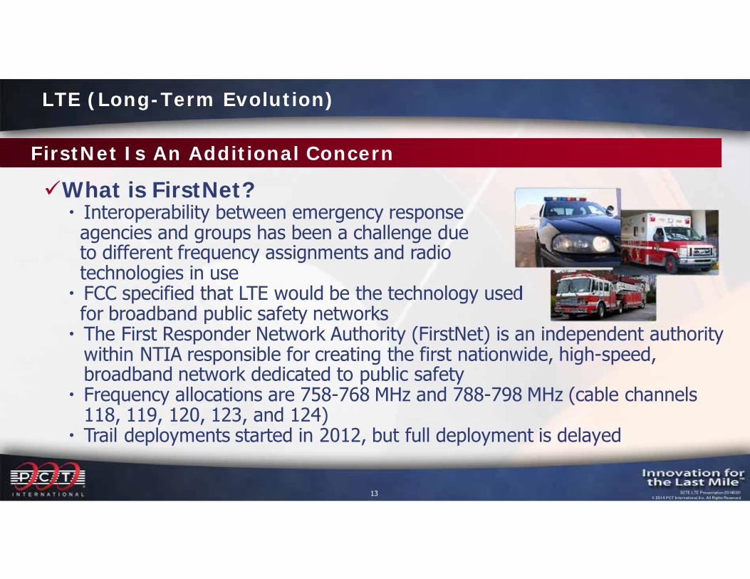
What is FirstNet? Interoperability between emergency responseagencies and groups has been a challenge dueto different frequency assignments and radio technologies in use FCC specified that LTE would be the technology usedfor broadband public safety networks The First Responder Network Authority (FirstNet) is an independent authority
within NTIA responsible for creating the first nationwide, high-speed, broadband network dedicated to public safety
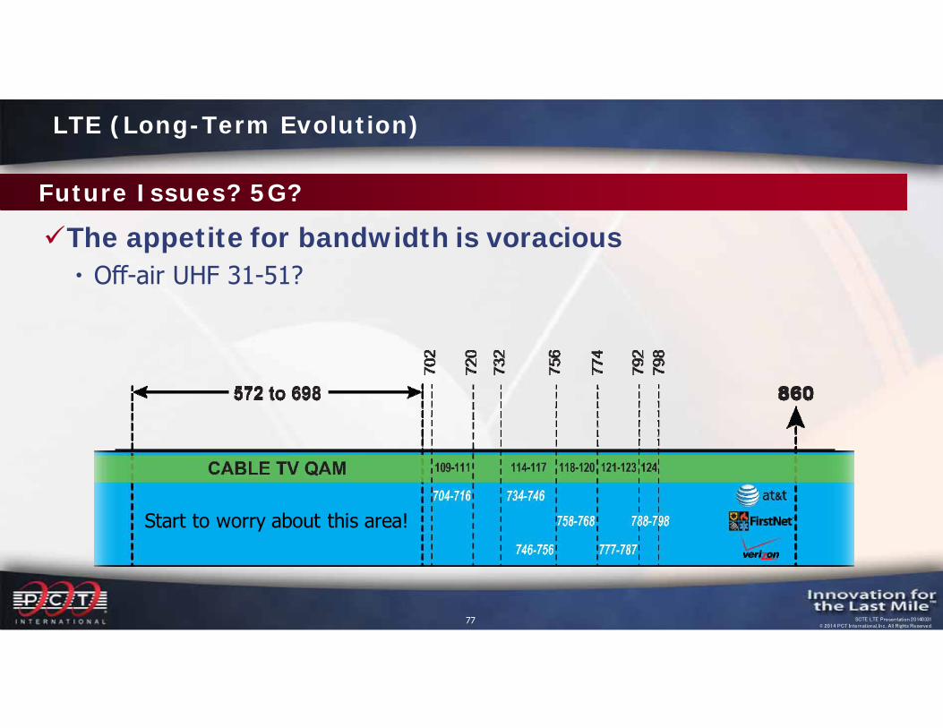
Frequency allocations are 758-768 MHz and 788-798 MHz (cable channels 118, 119, 120, 123, and 124)
Trail deployments started in 2012, but full deployment is delayed
FirstNet Is An Additional Concern
LTE (Long-Term Evolution)

14 SCTE LTE Presentation 20140331© 2014 PCT International, Inc. All Rights Reserved.
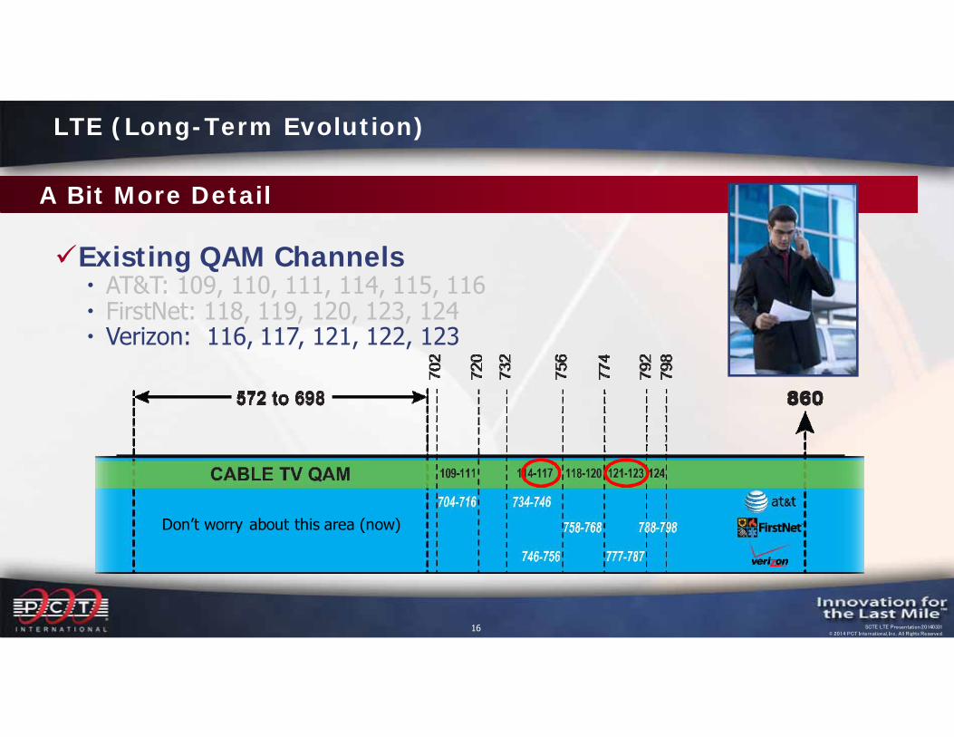
Existing QAM Channels AT&T: 109, 110, 111, 114, 115, 116 FirstNet: 118, 119, 120, 123, 124 Verizon: 116, 117, 121, 122, 123
A Bit More Detail
LTE (Long-Term Evolution)
Don’t worry about this area (now)

15 SCTE LTE Presentation 20140331© 2014 PCT International, Inc. All Rights Reserved.
Existing QAM Channels AT&T: 109, 110, 111, 114, 115, 116 FirstNet: 118, 119, 120, 123, 124 Verizon: 116, 117, 121, 122, 123
A Bit More Detail
LTE (Long-Term Evolution)
Don’t worry about this area (now)
16 SCTE LTE Presentation 20140331© 2014 PCT International, Inc. All Rights Reserved.
Existing QAM Channels AT&T: 109, 110, 111, 114, 115, 116 FirstNet: 118, 119, 120, 123, 124 Verizon: 116, 117, 121, 122, 123
A Bit More Detail
LTE (Long-Term Evolution)
Don’t worry about this area (now)

17 SCTE LTE Presentation 20140331© 2014 PCT International, Inc. All Rights Reserved.
Existing QAM Channels AT&T: 109, 110, 111, 114, 115, 116 FirstNet: 118, 119, 120, 123, 124 Verizon: 116, 117, 121, 122, 123
A Bit More Detail
LTE (Long-Term Evolution)
Don’t worry about this area (now)
18 SCTE LTE Presentation 20140331© 2014 PCT International, Inc. All Rights Reserved.
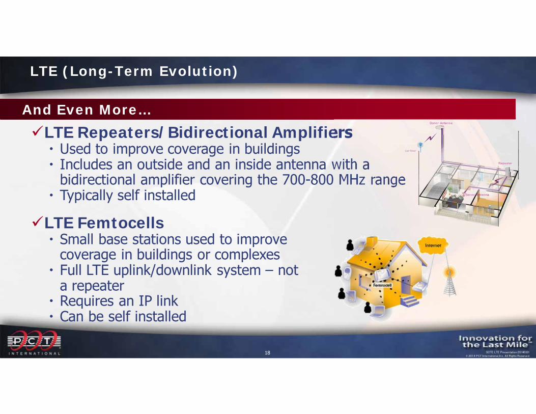
LTE Repeaters/Bidirectional Amplifiers Used to improve coverage in buildings Includes an outside and an inside antenna with a
bidirectional amplifier covering the 700-800 MHz range Typically self installed
LTE Femtocells Small base stations used to improve
coverage in buildings or complexes Full LTE uplink/downlink system – not
a repeater Requires an IP link Can be self installed
And Even More…
LTE (Long-Term Evolution)
19 SCTE LTE Presentation 20140331© 2014 PCT International, Inc. All Rights Reserved.
Time for a Review
Review of Leakage Issues All of these LTE signals are potential interference sources to our
networks Our networks are potential interference sources to these LTE signals Signals leaking into and out of our networks is a problem we’ve
been dealing with for many years We’re not done yet…
LTE (Long-Term Evolution)
20 SCTE LTE Presentation 20140331© 2014 PCT International, Inc. All Rights Reserved.
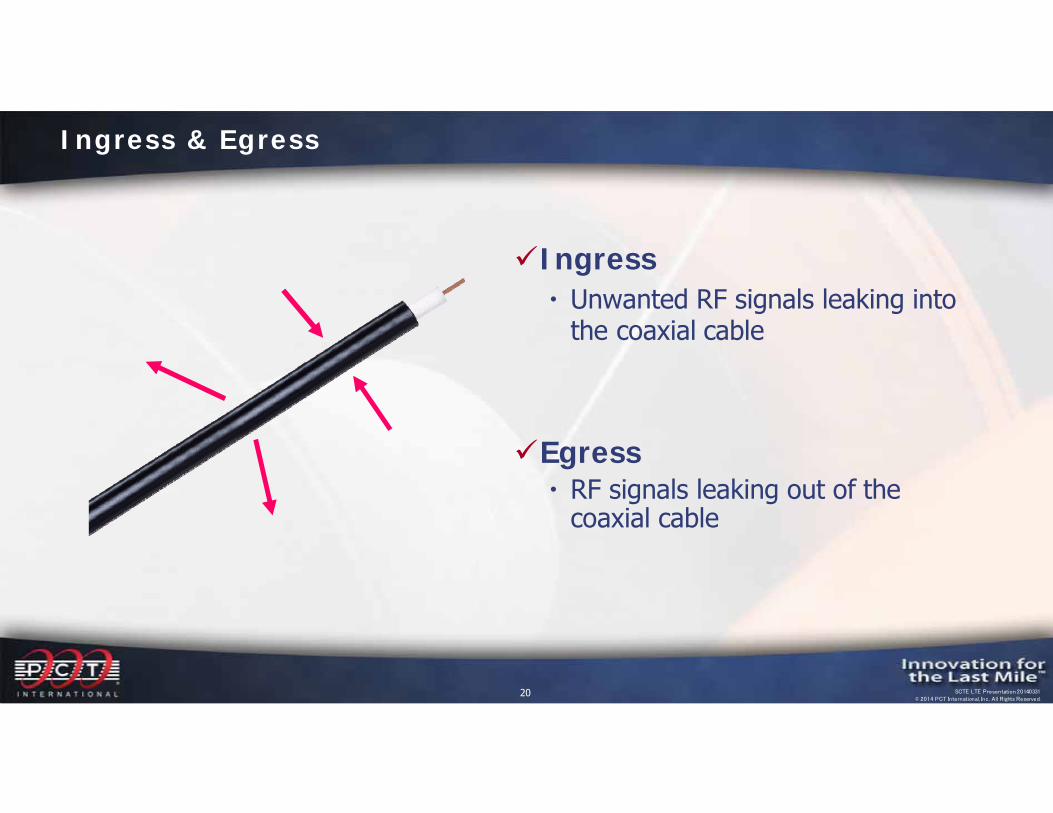
Ingress Unwanted RF signals leaking into
the coaxial cable
Egress RF signals leaking out of the
coaxial cable
Ingress & Egress

21 SCTE LTE Presentation 20140331© 2014 PCT International, Inc. All Rights Reserved.
Undesired emission of signals out of an HFC network (Egress)
What is Signal Leakage?
22 SCTE LTE Presentation 20140331© 2014 PCT International, Inc. All Rights Reserved.
Background
Two reported interference incidents got the FCC involvedOnly prior complaints were HAM operators and
occasional FM radio Cable network RF signals do not cause interference
when the system complies with Federal Communications Commission (FCC) rules for limiting interference
Signal Leakage (Egress)
23 SCTE LTE Presentation 20140331© 2014 PCT International, Inc. All Rights Reserved.
Background
Occasionally, however, cable television system signals can “leak” Cable signal leaks occur when the RF signals transmitted
within a cable system are not properly contained within the cable plant Cable signal leaks can be caused by a number of things,
including loose connectors, damaged plant and cracked or unterminated cables
Signal Leakage (Egress)
24 SCTE LTE Presentation 20140331© 2014 PCT International, Inc. All Rights Reserved.
Why Is Signal Leakage Monitoring Important?
Signal Leakage (Egress)
The FCC requires that we control signal leakagePrevents interference to authorized users of the
spectrumEliminates ingress into our networks, which can
interfere with our video and data servicesImproves the physical condition of our system

25 SCTE LTE Presentation 20140331© 2014 PCT International, Inc. All Rights Reserved.
Regulatory Requirements
Signal Leakage (Egress)
The FCC has set maximum leakage limits that apply to ALL parts of the cable telecommunications networkFCC 47 CFR 76.605 (a) 12 defines leakage limits
FCC 47 CFR 76.613 requires elimination of “harmful interference”, irrespective of the level of signal leakage
Frequency Limits54 – 216 MHz 20 µV/m @ 3 meters
> 216 MHz 15 µV/m @ 30 meters
26 SCTE LTE Presentation 20140331© 2014 PCT International, Inc. All Rights Reserved.
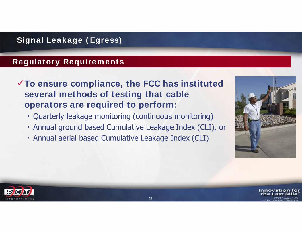
To ensure compliance, the FCC has instituted several methods of testing that cable operators are required to perform: Quarterly leakage monitoring (continuous monitoring) Annual ground based Cumulative Leakage Index (CLI), or Annual aerial based Cumulative Leakage Index (CLI)
Regulatory Requirements
Signal Leakage (Egress)
27 SCTE LTE Presentation 20140331© 2014 PCT International, Inc. All Rights Reserved.
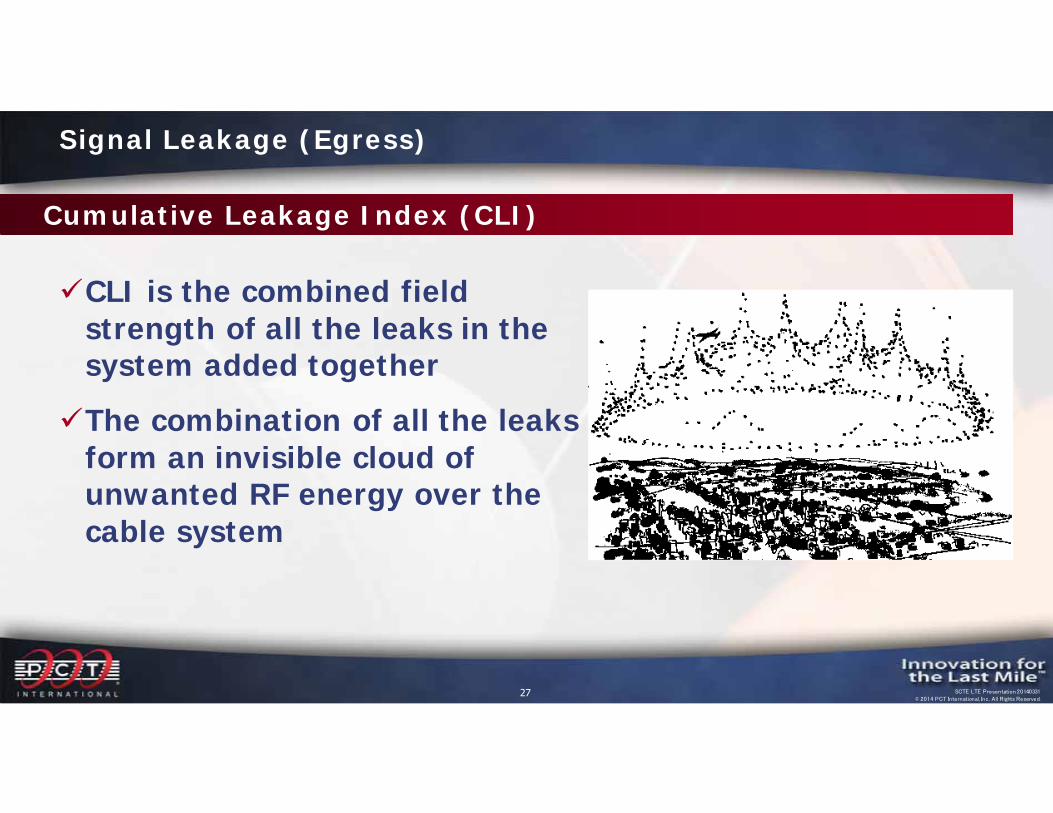
CLI is the combined field strength of all the leaks in the system added togetherThe combination of all the leaks
form an invisible cloud of unwanted RF energy over the cable system
Cumulative Leakage Index (CLI)
Signal Leakage (Egress)
28 SCTE LTE Presentation 20140331© 2014 PCT International, Inc. All Rights Reserved.
Why Is Signal Leakage Monitoring Important?
Signal Leakage (Egress)
The FCC requires we control signal leakagePrevents interference to authorized users of the
spectrumEliminates ingress into our networks, which can
interfere with our video and data servicesImproves the physical condition of our system
29 SCTE LTE Presentation 20140331© 2014 PCT International, Inc. All Rights Reserved.
The cable industry uses RF frequencies that are shared with Over-The-Air (OTA) broadcasters:
• Government• Military• Ham (amateur radio)• TV• Broadcast radio• Aeronautical radio • Cell phones• Among other users
Shared Frequencies
Signal Leakage (Egress)
30 SCTE LTE Presentation 20140331© 2014 PCT International, Inc. All Rights Reserved.
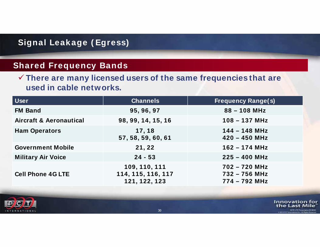
Shared Frequency Bands There are many licensed users of the same frequencies that are
used in cable networks.User Channels Frequency Range(s)FM Band 95, 96, 97 88 – 108 MHzAircraft & Aeronautical 98, 99, 14, 15, 16 108 – 137 MHzHam Operators 17, 18
57, 58, 59, 60, 61144 – 148 MHz420 – 450 MHz
Government Mobile 21, 22 162 – 174 MHzMilitary Air Voice 24 - 53 225 – 400 MHz
Cell Phone 4G LTE109, 110, 111
114, 115, 116, 117121, 122, 123
702 – 720 MHz 732 – 756 MHz774 – 792 MHz
Signal Leakage (Egress)
31 SCTE LTE Presentation 20140331© 2014 PCT International, Inc. All Rights Reserved.
What Problems Can Signal Leakage Cause?
It can endanger the lives or hamper the rescue efforts of safety personnel This interference, especially on the emergency channels,
can interfere with the communications of safety personnel or airplane pilots Cable signal leakage can interfere with any of the over-
the-air services that happen to be using the same frequencies as the cable operator and that are within the vicinity of the cable system
Signal Leakage (Egress)
32 SCTE LTE Presentation 20140331© 2014 PCT International, Inc. All Rights Reserved.
Why Is It Important to Control Leakage?
Cable operators are considered the secondary users of these frequencies; therefore they must not interfere with the licensed over-the-air users who are the protected (primary) users of these frequencies
Signal Leakage (Egress)
33 SCTE LTE Presentation 20140331© 2014 PCT International, Inc. All Rights Reserved.
Why Is Signal Leakage Monitoring Important?
Signal Leakage (Egress)
The FCC requires we control signal leakagePrevents interference to authorized users of the
spectrumImproves the physical condition of our systemEliminates ingress into our networks, which can
interfere with our video and data services
34 SCTE LTE Presentation 20140331© 2014 PCT International, Inc. All Rights Reserved.
The majority of all leakage is caused by problems between the tap and the customer premises equipment (CPE)The following is a small list of items that cause signal
leakage: Loose drop connectors Improper installation of connectors, coax, passives and
splices Poor quality coaxial cable, passives, or connectors Corroded connectors, dampness or the presence of water Physical damage to cables or connectors
Common Causes
Signal Leakage (Egress)
35 SCTE LTE Presentation 20140331© 2014 PCT International, Inc. All Rights Reserved.
Common Causes Continued
• Product aging due to environmental conditions• Bad/loose port terminator • Unterminated ports on taps, passives and actives• Broken tap ports• CPE or shielding of equipment (e.g., faulty VCR or poorly
shielded TV set)• Squirrel/Rodent chews• Customer installed equipment• Loose hard line connectors• Damaged amplifier housings and loose housing lids
Signal Leakage (Egress)
36 SCTE LTE Presentation 20140331© 2014 PCT International, Inc. All Rights Reserved.
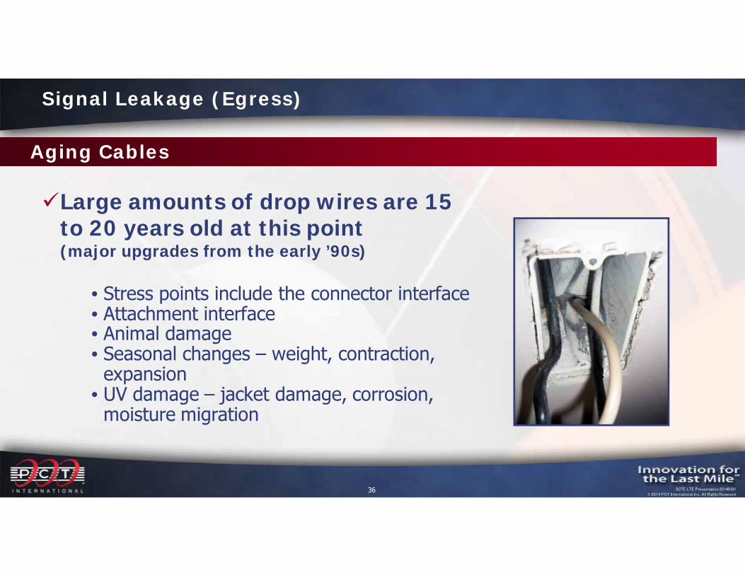
Aging Cables
Large amounts of drop wires are 15 to 20 years old at this point (major upgrades from the early ’90s)
• Stress points include the connector interface• Attachment interface• Animal damage• Seasonal changes – weight, contraction,
expansion• UV damage – jacket damage, corrosion,
moisture migration
Signal Leakage (Egress)
37 SCTE LTE Presentation 20140331© 2014 PCT International, Inc. All Rights Reserved.
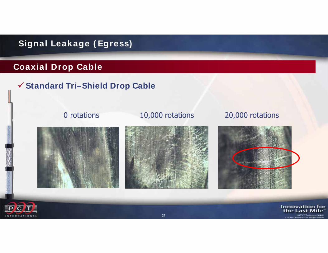
Coaxial Drop Cable
Standard Tri–Shield Drop Cable
0 rotations 10,000 rotations 20,000 rotations
Signal Leakage (Egress)

38 SCTE LTE Presentation 20140331© 2014 PCT International, Inc. All Rights Reserved.
S – Bend Testing
50 Times Conduits Prewired homes tight bends Wall plate tight turns Home entry points
Signal Leakage (Egress)
39 SCTE LTE Presentation 20140331© 2014 PCT International, Inc. All Rights Reserved.
Why Is Signal Leakage Monitoring Important?
Signal Leakage (Egress)
The FCC requires we control signal leakagePrevents interference to authorized users of the
spectrumImproves the physical condition of our systemEliminates ingress into our networks, which can
interfere with our video and data services
40 SCTE LTE Presentation 20140331© 2014 PCT International, Inc. All Rights Reserved.
Undesired entry of signals into an HFC network (Ingress)
What is Signal Ingress?
41 SCTE LTE Presentation 20140331© 2014 PCT International, Inc. All Rights Reserved.
It is possible that OTA signals can leak into a drop (ingress) and cause problems on both the forward and reverse signalsThe interference is often bursty or impulsive in nature,
although it can also be a continuous increase in the system noise floor To locate the place where signal is leaking in, use the
"divide and conquer" method The mostly likely cause of the problem will be a bad or
loose F-connector, a break in the drop cable's shield, an old push-on jumper or bad wiring
Ingress
42 SCTE LTE Presentation 20140331© 2014 PCT International, Inc. All Rights Reserved.
Reverse Ingress
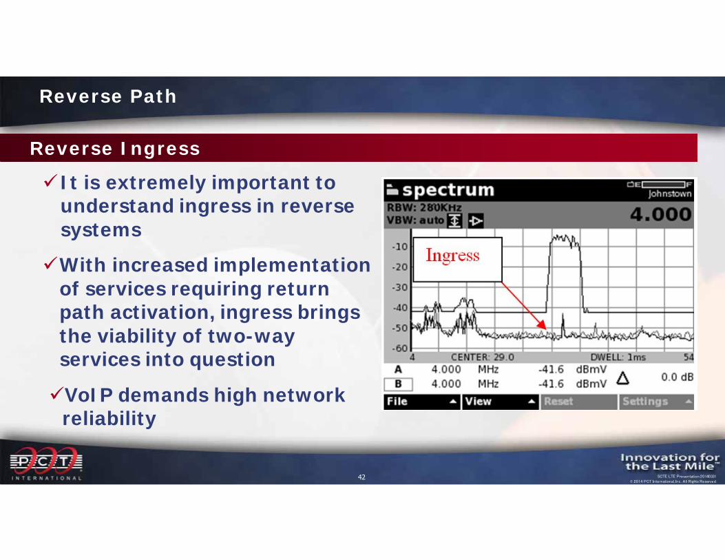
It is extremely important to understand ingress in reverse systems
With increased implementation of services requiring return path activation, ingress brings the viability of two-way services into questionVoIP demands high network
reliability
Reverse Path

43 SCTE LTE Presentation 20140331© 2014 PCT International, Inc. All Rights Reserved.
Ingress is a significant issue at the lower frequencies Lower frequencies travel farther through the air with less loss than high
frequencies Many interference sources (electric motors, welders, etc.) generate
more RF energy at the low frequencies
Prevention of ingress problems can save time and costs involved with later "truck rolls" 95% of the ingress on the return path occurs from the tap
through the customers premise - over 75% of the ingress occurs within the house
Reverse Path
Reverse Ingress
44 SCTE LTE Presentation 20140331© 2014 PCT International, Inc. All Rights Reserved.
Reverse Ingress
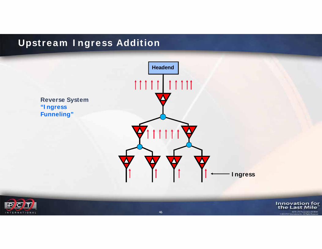
Ingress is a major concern in cable networks due to what is referred to as “funneling” Funneling is the result of sources of ingress and other
interference harmful to reliable operation being picked up at multiple locations and funneled back to the receiver at the headend/hub, similar to noise in the reverse network
Reverse Path
45 SCTE LTE Presentation 20140331© 2014 PCT International, Inc. All Rights Reserved.
Reverse Ingress
Ingress on the return path is summed together - it only takes one bad house to corrupt an entire node! Each home’s ingress is combined together and increases
the total ingress noise level received at the hub, which affects all homes serviced by a node Therefore, it is important to minimize and control the
ingress at each individual home
Reverse Path
46 SCTE LTE Presentation 20140331© 2014 PCT International, Inc. All Rights Reserved.
Headend
Reverse System “Ingress Funneling”
Ingress
Upstream Ingress Addition

47 SCTE LTE Presentation 20140331© 2014 PCT International, Inc. All Rights Reserved.
The 5-42 MHz reverse spectrum is shared with numerous over-the-air users.
Signals in the over-the-air environment include high power shortwave broadcasts, amateur radio, citizens band, government, and other two-way radio communications.
Reverse Path Impairments
RF Ingress
48 SCTE LTE Presentation 20140331© 2014 PCT International, Inc. All Rights Reserved.
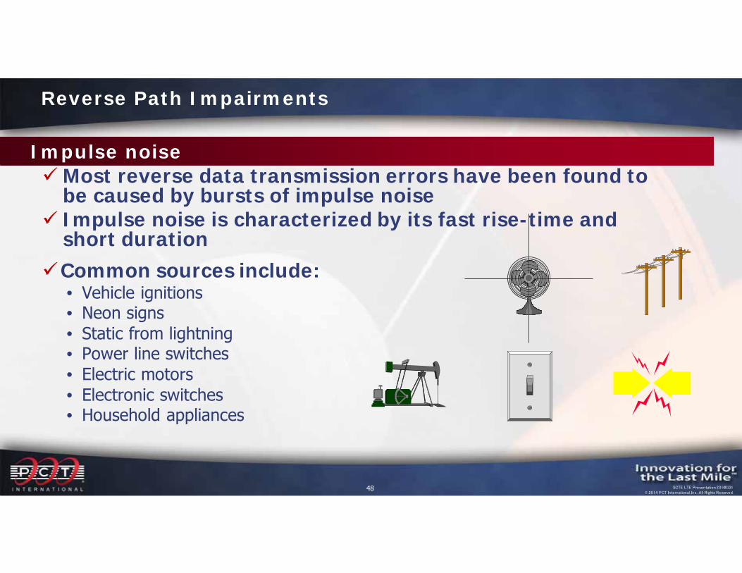
Most reverse data transmission errors have been found to be caused by bursts of impulse noise
Impulse noise is characterized by its fast rise-time and short duration
Common sources include: • Vehicle ignitions• Neon signs• Static from lightning• Power line switches• Electric motors• Electronic switches • Household appliances
Reverse Path Impairments
Impulse noise

49 SCTE LTE Presentation 20140331© 2014 PCT International, Inc. All Rights Reserved.
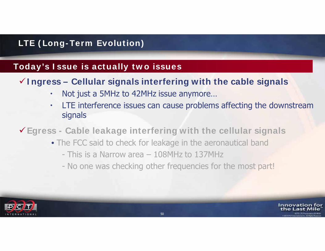
Today’s Issue is actually two issues
Ingress – Cellular signals interfering with the cable signals Not just a 5MHz to 42MHz issue anymore… LTE interference issues can cause problems affecting the downstream
signals
Egress - Cable leakage interfering with the cellular signals• The FCC said to check for leakage in the aeronautical band
- This is a Narrow area – 108MHz to 137MHz- No one was checking other frequencies for the most part!
LTE (Long-Term Evolution)
50 SCTE LTE Presentation 20140331© 2014 PCT International, Inc. All Rights Reserved.
Today’s Issue is actually two issues
Ingress – Cellular signals interfering with the cable signals Not just a 5MHz to 42MHz issue anymore… LTE interference issues can cause problems affecting the downstream
signals
Egress - Cable leakage interfering with the cellular signals• The FCC said to check for leakage in the aeronautical band
- This is a Narrow area – 108MHz to 137MHz- No one was checking other frequencies for the most part!
LTE (Long-Term Evolution)
51 SCTE LTE Presentation 20140331© 2014 PCT International, Inc. All Rights Reserved.
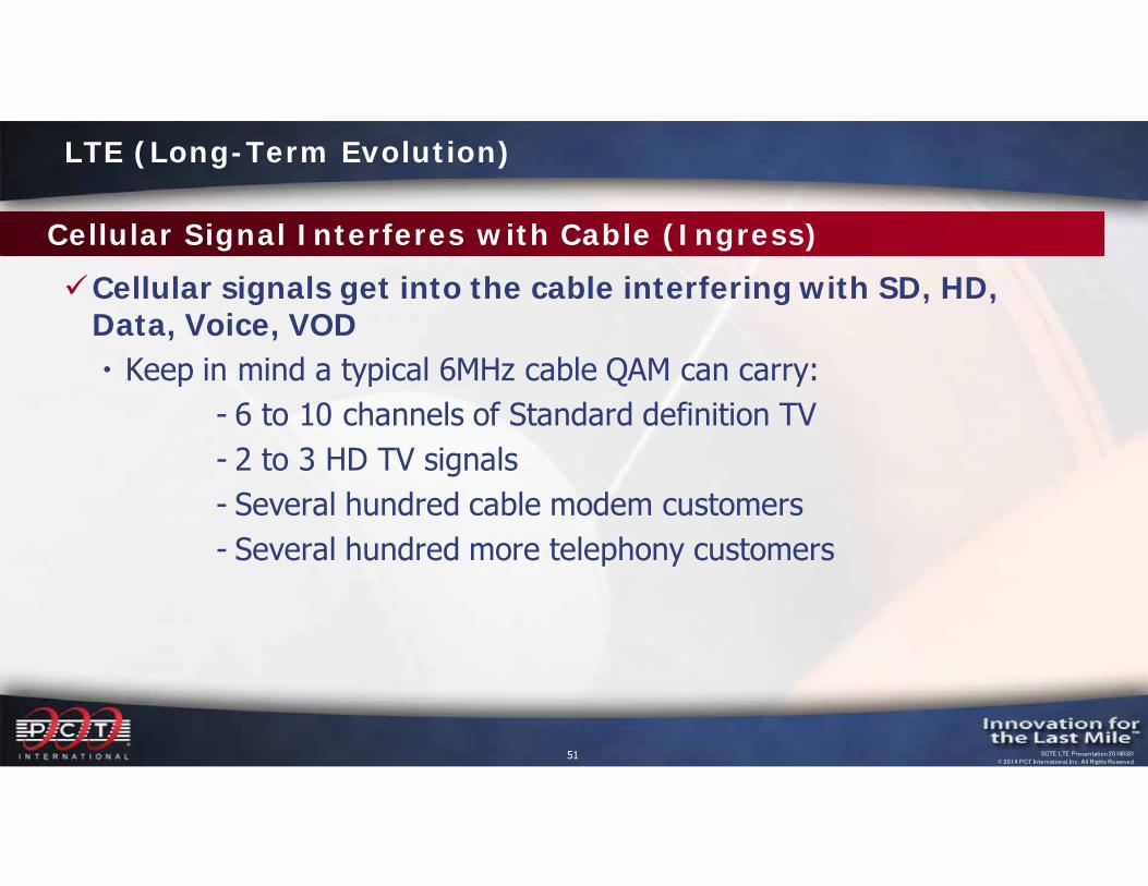
Cellular Signal Interferes with Cable (Ingress)
Cellular signals get into the cable interfering with SD, HD, Data, Voice, VOD Keep in mind a typical 6MHz cable QAM can carry:
- 6 to 10 channels of Standard definition TV- 2 to 3 HD TV signals- Several hundred cable modem customers- Several hundred more telephony customers
LTE (Long-Term Evolution)
52 SCTE LTE Presentation 20140331© 2014 PCT International, Inc. All Rights Reserved.
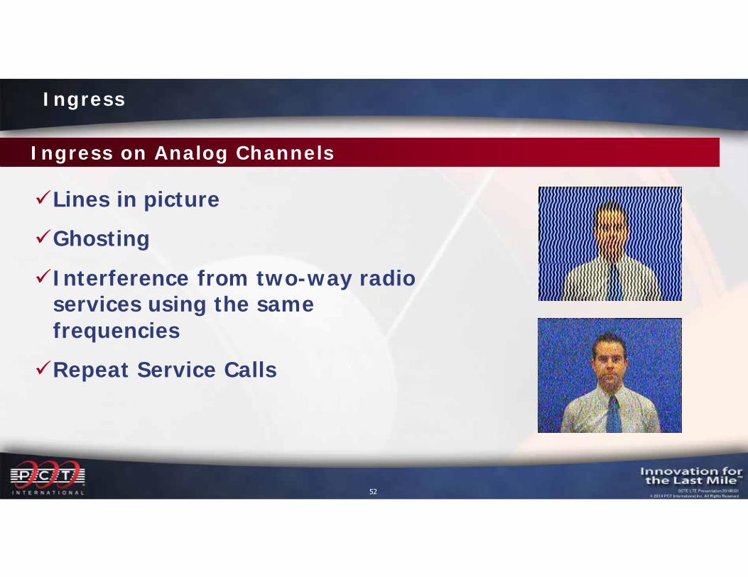
Ingress on Analog Channels
Lines in pictureGhostingInterference from two-way radio
services using the same frequenciesRepeat Service Calls
Ingress
53 SCTE LTE Presentation 20140331© 2014 PCT International, Inc. All Rights Reserved.
The same problems in the coax network that have been described (bad cable, fittings, etc.) have different symptoms or artifacts on digital television channels. Although the "fix" is the same, for digital channels, MER/BER can be used to isolate the cause.
Digital Video Impairments From Ingress
54 SCTE LTE Presentation 20140331© 2014 PCT International, Inc. All Rights Reserved.
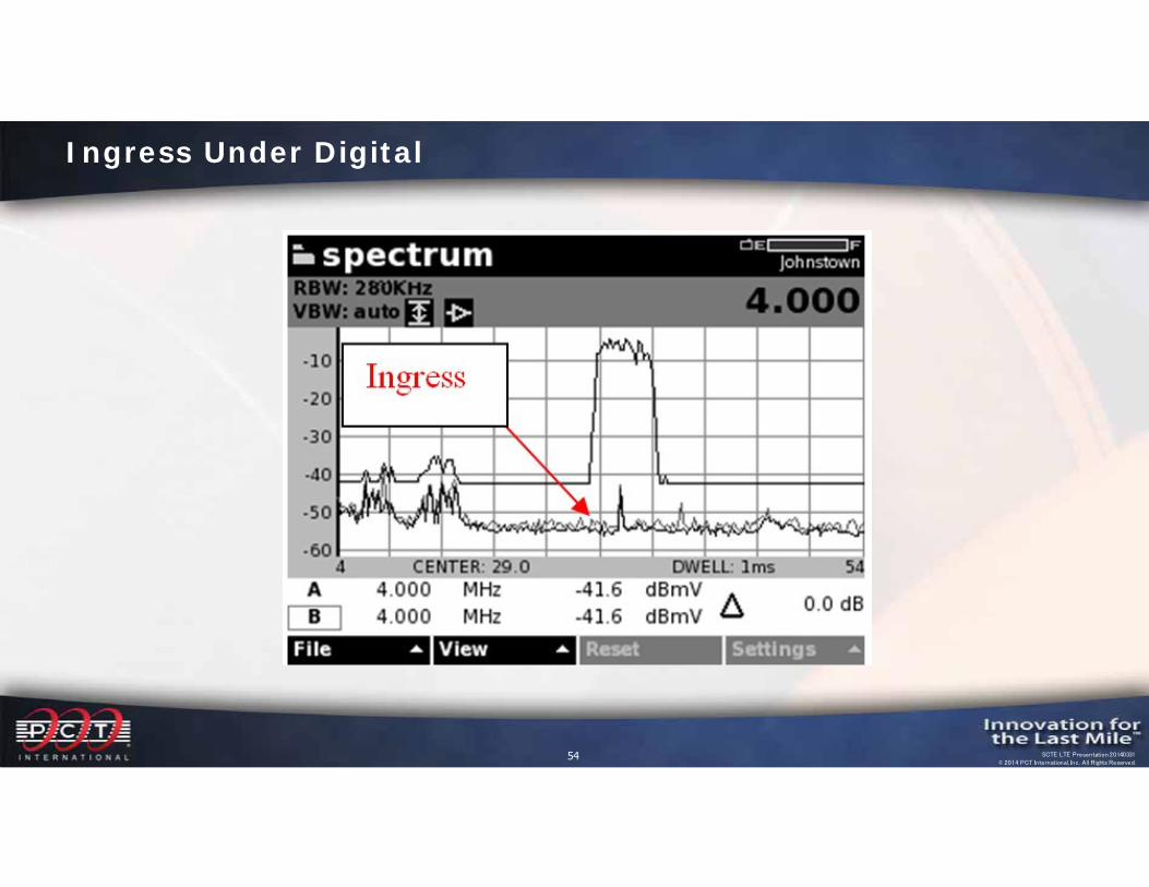
Ingress Under Digital
55 SCTE LTE Presentation 20140331© 2014 PCT International, Inc. All Rights Reserved.
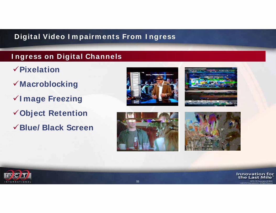
PixelationMacroblockingImage FreezingObject RetentionBlue/Black Screen
Digital Video Impairments From Ingress
Ingress on Digital Channels
56 SCTE LTE Presentation 20140331© 2014 PCT International, Inc. All Rights Reserved.
Today’s Issue is actually two issues (2)
Ingress – Cellular signals interfering with the cable signals Not just a 5MHz to 42MHz issue anymore… Ingress issues can now cause problems affecting the downstream
signals
Egress - Cable leakage interfering with the cellular signals• The FCC said to check for leakage in the aeronautical band
- This is a narrow range – 108 MHz to 137 MHz- No one was checking other frequencies for the most part!
LTE (Long-Term Evolution)
57 SCTE LTE Presentation 20140331© 2014 PCT International, Inc. All Rights Reserved.
Cable QAMs Interfere with Cellular (Egress)
QAM signals leaking out of the cable network• Interfere with cellular reception‒How? Cable QAM signals might be stronger or equal to cell device signal
• Interfere with cellular transmission‒How? Low power transmissions from cell device may be equal to local leakage
LTE (Long-Term Evolution)
58 SCTE LTE Presentation 20140331© 2014 PCT International, Inc. All Rights Reserved.
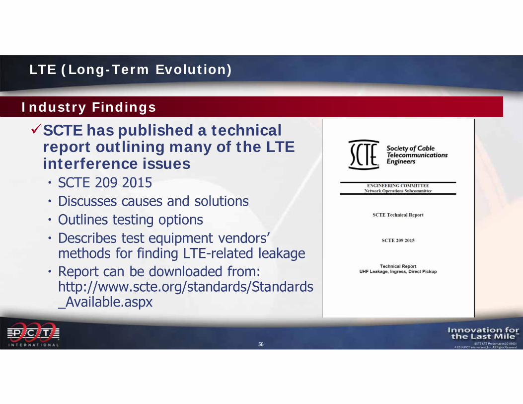
Industry Findings
SCTE has published a technical report outlining many of the LTE interference issues SCTE 209 2015 Discusses causes and solutions Outlines testing options Describes test equipment vendors’
methods for finding LTE-related leakage Report can be downloaded from:
http://www.scte.org/standards/Standards_Available.aspx
LTE (Long-Term Evolution)
59 SCTE LTE Presentation 20140331© 2014 PCT International, Inc. All Rights Reserved.
Industry Findings
A lot of work is being done by both operators and test equipment manufacturers to help better identify what is going on with LTE interferenceThe following slides describe some of the industry
findings regarding this issue
LTE (Long-Term Evolution)
60 SCTE LTE Presentation 20140331© 2014 PCT International, Inc. All Rights Reserved.
Industry Findings
Leaks can be frequency specific• A leak at 700 MHz can occur when no leak is measured in the
aeronautical band (108 – 137 MHz)
The shape and dimensions of the leak source are significant Determines how it acts as an antenna Impacts the way the leak propagates at different frequencies Affects the level of the leak
LTE (Long-Term Evolution)
61 SCTE LTE Presentation 20140331© 2014 PCT International, Inc. All Rights Reserved.
Industry Findings
Leaks are more likely at higher frequencies than at lower frequencies• Smaller breaks in shielding allow shorter wavelengths to propagate
out of the network• Testing performed by Rohde & Schwarz shows the following:
• ~30% of all leaks found are in the VHF range• ~50% of all leaks found are in the 700 MHz range• ~20% of all leaks occur over a wide frequency range (100 MHz to 800 MHz)
LTE (Long-Term Evolution)
62 SCTE LTE Presentation 20140331© 2014 PCT International, Inc. All Rights Reserved.
Industry Findings
Leaks are more likely at higher frequencies than at lower frequencies• Smaller breaks in shielding allow shorter wavelengths to propagate
out of the network• Testing performed by Arcom Digital shows the following:
• ~13% of all leaks found are in the VHF range• ~67% of all leaks found are in the 700 MHz range• ~20% of all leaks occur over a wide frequency range (139 MHz and 735 MHz)
LTE (Long-Term Evolution)
63 SCTE LTE Presentation 20140331© 2014 PCT International, Inc. All Rights Reserved.
Industry FindingsLeaks can occur at different levels at different
frequencies• One documented case found a 10 µV/M leak at 137 MHz from a bad
tap that was measured 40 dB higher, or 1000 µV/M, at 700MHz!• Several studies by MSOs and test equipment manufacturers have
found less extreme cases, but <10 µV/M leaks at 137 MHz are commonly found to be leaking at >150 µV/M at 700MHz
• No correlation can be made between VHF and UHF leakage levels
LTE (Long-Term Evolution)

64 SCTE LTE Presentation 20140331© 2014 PCT International, Inc. All Rights Reserved.
Industry FindingsIngress/Egress levels are not always linear Field testing is showing that a high level leak does not always mean
a high level of ingress at the same location, and vice versa The shape of the leak source will impact both the ingress and
egress potential of the fault in the network Lower signal levels on the network mean smaller leaks when
compared to potential ingress signal levels
LTE (Long-Term Evolution)
65 SCTE LTE Presentation 20140331© 2014 PCT International, Inc. All Rights Reserved.
Industry Findings
A major source of LTE Ingress and Egress is the drop• Same causes as in the aeronautical band (108 – 137 MHz) ‒Loose connectors‒Age & Stress‒Physical trauma‒Poor coax, passives, or connectors‒Customer premises equipment
LTE (Long-Term Evolution)
66 SCTE LTE Presentation 20140331© 2014 PCT International, Inc. All Rights Reserved.
Industry FindingsThe outside plant is also a major source of LTE Ingress and Egress
• Higher signal levels in the OSP have the potential to create higher level leaks• Loose or warped tap faceplates make an excellent UHF slot antenna
• Free space quarter wavelength at 750 MHz = 3.93”• Loose hardline connectors make an excellent UHF slot antenna
• Threaded nut on the back of a .500 connector is approximately 3” diameter• Other OSP faults can be UHF leakage sources
‒Radial cracks in expansion loops‒Animal chews
• Again, the shape and the dimensions of the leak source and how they act as an antenna will all impact leaks at different frequencies
LTE (Long-Term Evolution)
67 SCTE LTE Presentation 20140331© 2014 PCT International, Inc. All Rights Reserved.
Industry Findings
Set Top Boxes and Cable Modems are not immune An independent study showed that 7 out of 9 STBs showed the effects
of ingress from LTE signals The same study showed that 12 out of 12 CMs showed the effects of
ingress from LTE signals
LTE (Long-Term Evolution)
68 SCTE LTE Presentation 20140331© 2014 PCT International, Inc. All Rights Reserved.
Shielding Effectiveness Performance
To prevent both ingress and egress, the shielding effectiveness of all components must be maintained 4G/LTE cell phones transmit at up to 200 mW With 256 QAM, shielding effectiveness must be better than 84 dB to
ensure 35 dB CNR performance in the presence of cell phone signals This means all components in the network must maintain shielding
effectiveness of greater than 84 dB to ensure handheld cell phones don’t interfere with the cable signals, and that the signals in the network don’t interfere with the handheld cell phone
LTE (Long-Term Evolution)
69 SCTE LTE Presentation 20140331© 2014 PCT International, Inc. All Rights Reserved.
Shielding Effectiveness Performance
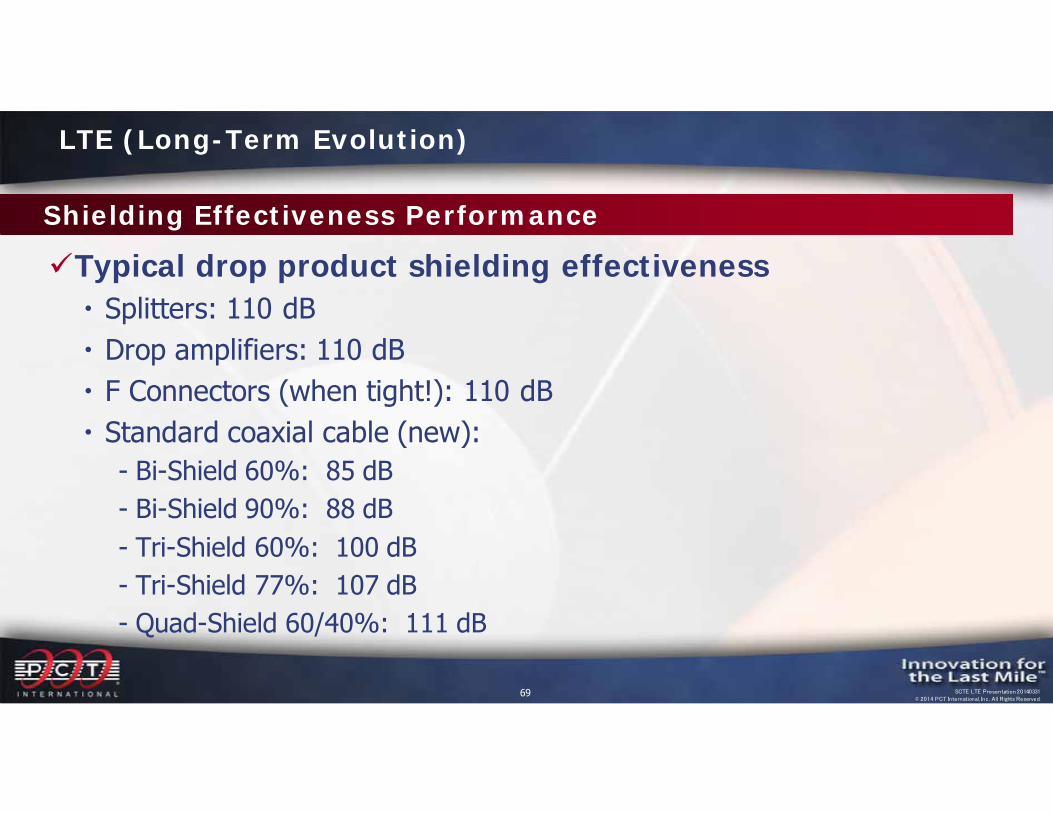
Typical drop product shielding effectiveness Splitters: 110 dB Drop amplifiers: 110 dB F Connectors (when tight!): 110 dB Standard coaxial cable (new):
- Bi-Shield 60%: 85 dB- Bi-Shield 90%: 88 dB- Tri-Shield 60%: 100 dB- Tri-Shield 77%: 107 dB- Quad-Shield 60/40%: 111 dB
LTE (Long-Term Evolution)
70 SCTE LTE Presentation 20140331© 2014 PCT International, Inc. All Rights Reserved.
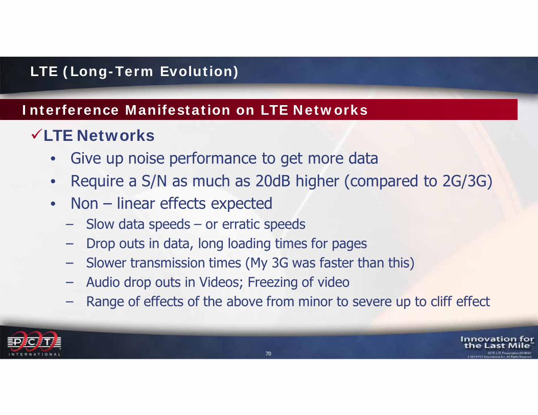
Interference Manifestation on LTE Networks
LTE Networks• Give up noise performance to get more data• Require a S/N as much as 20dB higher (compared to 2G/3G)• Non – linear effects expected‒ Slow data speeds – or erratic speeds‒ Drop outs in data, long loading times for pages‒ Slower transmission times (My 3G was faster than this)‒ Audio drop outs in Videos; Freezing of video‒ Range of effects of the above from minor to severe up to cliff effect
LTE (Long-Term Evolution)
71 SCTE LTE Presentation 20140331© 2014 PCT International, Inc. All Rights Reserved.
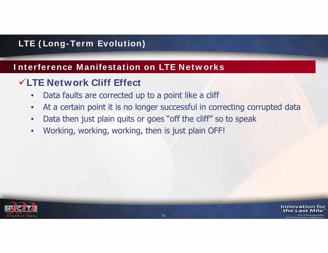
Interference Manifestation on LTE Networks
LTE Network Cliff Effect• Data faults are corrected up to a point like a cliff• At a certain point it is no longer successful in correcting corrupted data• Data then just plain quits or goes “off the cliff” so to speak• Working, working, working, then is just plain OFF!
LTE (Long-Term Evolution)
72 SCTE LTE Presentation 20140331© 2014 PCT International, Inc. All Rights Reserved.
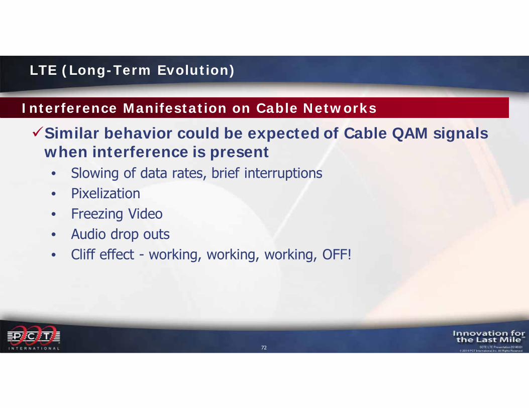
Interference Manifestation on Cable Networks
Similar behavior could be expected of Cable QAM signals when interference is present• Slowing of data rates, brief interruptions• Pixelization• Freezing Video• Audio drop outs• Cliff effect - working, working, working, OFF!
LTE (Long-Term Evolution)
73 SCTE LTE Presentation 20140331© 2014 PCT International, Inc. All Rights Reserved.
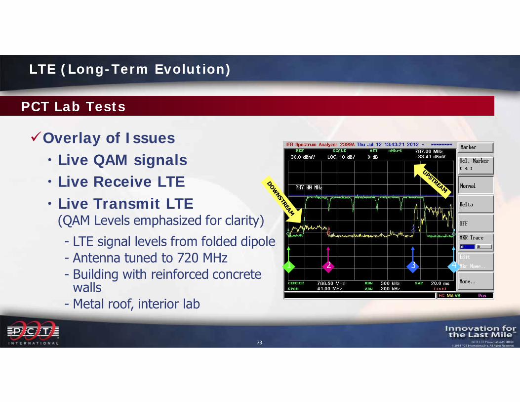
PCT Lab Tests
Overlay of Issues Live QAM signals Live Receive LTE Live Transmit LTE
(QAM Levels emphasized for clarity)- LTE signal levels from folded dipole- Antenna tuned to 720 MHz- Building with reinforced concrete
walls- Metal roof, interior lab
3 421
LTE (Long-Term Evolution)
74 SCTE LTE Presentation 20140331© 2014 PCT International, Inc. All Rights Reserved.
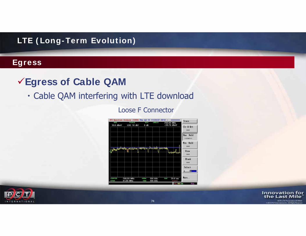
Egress
Egress of Cable QAM Cable QAM interfering with LTE download
Loose F Connector
LTE (Long-Term Evolution)
75 SCTE LTE Presentation 20140331© 2014 PCT International, Inc. All Rights Reserved.
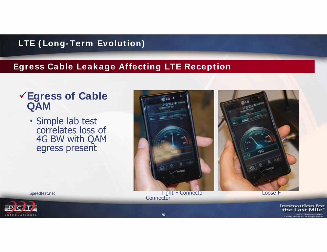
Egress Cable Leakage Affecting LTE Reception
Egress of Cable QAM Simple lab test
correlates loss of 4G BW with QAM egress present
Speedtest.net Tight F Connector Loose F Connector
LTE (Long-Term Evolution)
76 SCTE LTE Presentation 20140331© 2014 PCT International, Inc. All Rights Reserved.
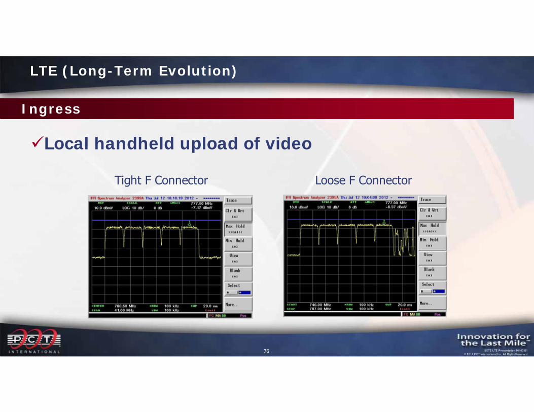
Ingress
Local handheld upload of video
Tight F Connector Loose F Connector
LTE (Long-Term Evolution)
77 SCTE LTE Presentation 20140331© 2014 PCT International, Inc. All Rights Reserved.
Future Issues? 5G?
The appetite for bandwidth is voracious Off-air UHF 31-51?
LTE (Long-Term Evolution)
Start to worry about this area!
78 SCTE LTE Presentation 20140331© 2014 PCT International, Inc. All Rights Reserved.
Round 2? Is it possible?
FCC 600 MHz Incentive Auction in early 2016 Part of the National Broadband Plan Will be auctioned off for LTE type services or similar wireless
services through a two tiered process- Reverse auction to determine prices at which broadcasters are prepared
to give up channel space and to determine the amount of spectrum to be auctioned
- Forward auction to determine how much cellular operators are willing to pay to acquire the spectrum
- Maximum range of 548MHz – 698MHz (TV Ch. 27-51) to be vacated- Minimum range of 656MHz – 698 MHz (TV Ch. 45-51) to be vacated
LTE (Long-Term Evolution)
79 SCTE LTE Presentation 20140331© 2014 PCT International, Inc. All Rights Reserved.
Round 2? Is it possible?
FCC 600 MHz Incentive Auction in early 2016 FCC to “repack” the remaining spectrum to accommodate
broadcasters that don’t participate Broadcasters that do participate share in the auction proceeds
- Vacate the broadcast spectrum altogether- Share spectrum with other broadcasters
The result of the “refarming” of this spectrum would create a greater overlap between the cable industry and cellular systems
LTE (Long-Term Evolution)
80 SCTE LTE Presentation 20140331© 2014 PCT International, Inc. All Rights Reserved.
Another Concern
TVWS NLOS (non-line-of-sight) fixed wireless broadband system Unlicensed transmission in “unused” frequencies between
existing TV channels Designed to detect and protect off-air television service
(cognitive radio technology) Automatically logs into national database to activate/authorize
service and download local channel plans Can operate anywhere in the TV broadcast VHF/UHF spectrum
(54 to 698 MHz)
Television White Spaces (TVWS)

81 SCTE LTE Presentation 20140331© 2014 PCT International, Inc. All Rights Reserved.
Another Concern
TVWS Two standards have been approved
- IEEE 802.22 (WRAN – up to 100 km – long term/permanent service)- IEEE 802.11af (Super Wi-Fi or WLAN – up to 5 km – temporary service)
Incorporates channel bonding (2 to 4 channels) Initially intended for rural deployments (802.22) Can be used anywhere (802.11af)
Television White Spaces (TVWS)
82 SCTE LTE Presentation 20140331© 2014 PCT International, Inc. All Rights Reserved.
Finding Leaks at 700 MHz
Current leakage equipment isn’t designed for 700 MHz Current equipment is generally just for the aeronautical band
(108 – 137 MHz) New methods under development by test equipment
manufacturers
DIY methods can be used Most reliable method uses a spectrum analyzer, high-gain
directional antenna, preamplifier, and bandpass filter
Leakage Mitigation
83 SCTE LTE Presentation 20140331© 2014 PCT International, Inc. All Rights Reserved.
Finding Leaks at 700 MHz
DIY methods can be used Field Strength Meter method
- Effective for high level leaks and when close to leaks- Uses the spectrum analysis mode- Only indicates the existence of leakage and does not provide exact
measurements of the leak- Requires an antenna designed for 700 MHz
Leakage Mitigation

84 SCTE LTE Presentation 20140331© 2014 PCT International, Inc. All Rights Reserved.
Finding Leaks at 700 MHz
Cox Communications in Phoenix has been using the following antenna design to successfully find leakage at 700 MHz Cut a 26” piece of RG-6 cable Install an F connector on one end of the cable Carefully remove ½” of the jacket ONLY approximately 6” from the
connector, leaving the braid and tape intact At the opposite end of the cable, remove the braid and dielectric to
expose 2” of center conductor(continued on next page)
Leakage Mitigation
85 SCTE LTE Presentation 20140331© 2014 PCT International, Inc. All Rights Reserved.
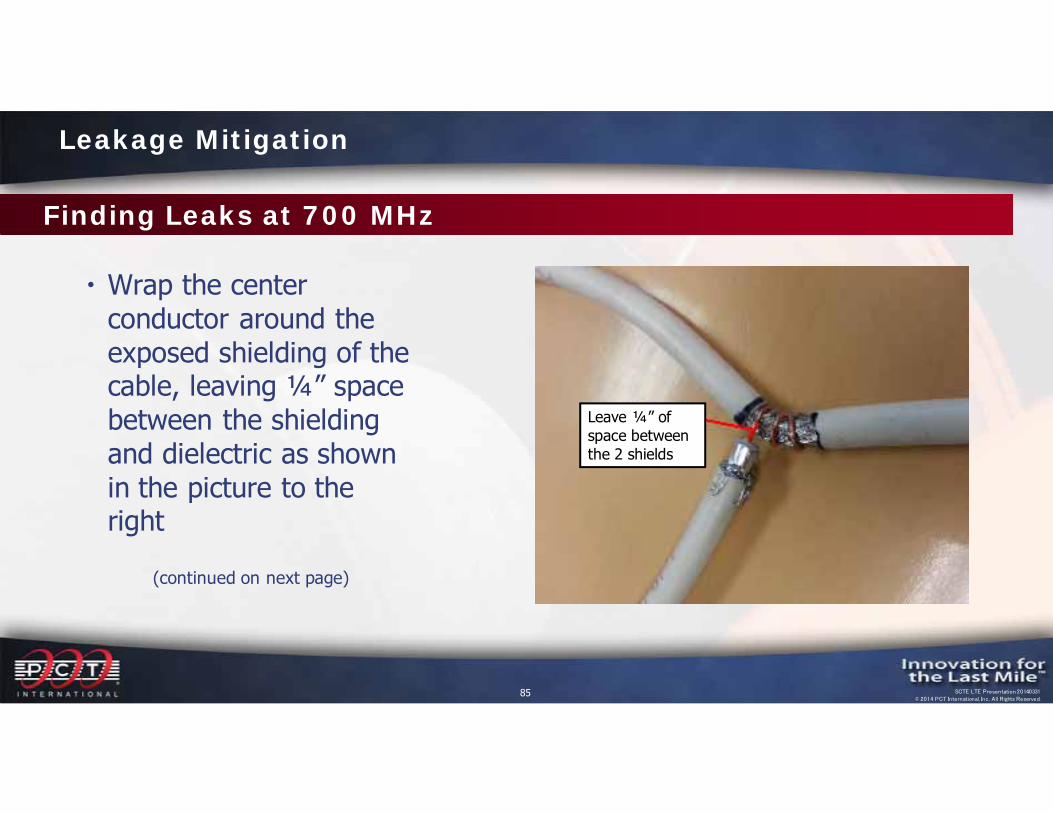
Finding Leaks at 700 MHz
Wrap the center conductor around the exposed shielding of the cable, leaving ¼” space between the shielding and dielectric as shown in the picture to the right
(continued on next page)
Leakage Mitigation
Leave ¼” of space between the 2 shields

86 SCTE LTE Presentation 20140331© 2014 PCT International, Inc. All Rights Reserved.
Finding Leaks at 700 MHz
Wrap the exposed dielectric and shielding with black electrical tape as shown in the picture to the right, making sure it does not touch the shielding on the cable where the center conductor is wrapped.
(continued on next page)
Leakage Mitigation
Wrap the ¼” space with electrical tape
87 SCTE LTE Presentation 20140331© 2014 PCT International, Inc. All Rights Reserved.
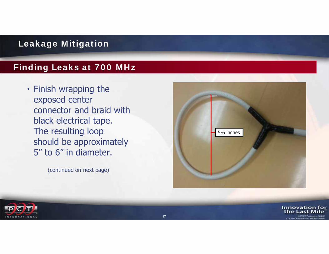
Finding Leaks at 700 MHz
Finish wrapping the exposed center connector and braid with black electrical tape. The resulting loop should be approximately 5” to 6” in diameter.
(continued on next page)
Leakage Mitigation
5-6 inches
88 SCTE LTE Presentation 20140331© 2014 PCT International, Inc. All Rights Reserved.
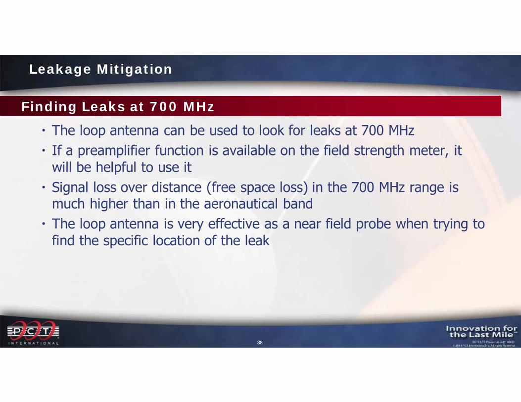
Finding Leaks at 700 MHz
The loop antenna can be used to look for leaks at 700 MHz If a preamplifier function is available on the field strength meter, it
will be helpful to use it Signal loss over distance (free space loss) in the 700 MHz range is
much higher than in the aeronautical band The loop antenna is very effective as a near field probe when trying to
find the specific location of the leak
Leakage Mitigation
89 SCTE LTE Presentation 20140331© 2014 PCT International, Inc. All Rights Reserved.
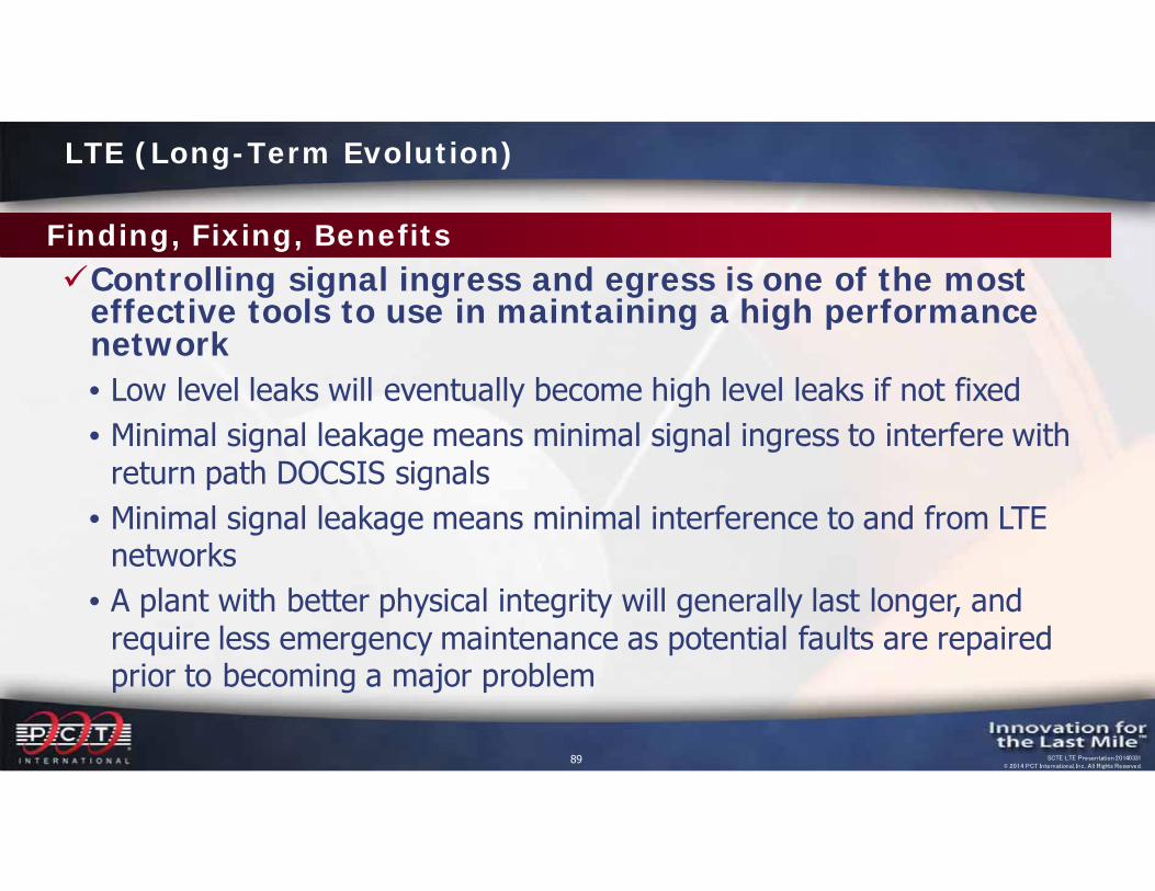
Controlling signal ingress and egress is one of the most effective tools to use in maintaining a high performance network• Low level leaks will eventually become high level leaks if not fixed• Minimal signal leakage means minimal signal ingress to interfere with
return path DOCSIS signals • Minimal signal leakage means minimal interference to and from LTE
networks• A plant with better physical integrity will generally last longer, and
require less emergency maintenance as potential faults are repaired prior to becoming a major problem
Finding, Fixing, Benefits
LTE (Long-Term Evolution)
pctinternational.com
SCTE LTE Presentation 20130905© 2013 PCT International, Inc. All Rights Reserved.
LTE Interference