ltcs20220w :01 mfl31442314 quantum inverter
DESCRIPTION
MODELS:LTCS20220W /01 LTCS20220B /01 LTCS20220S /01TRANSCRIPT

MODELS:LTCS20220W /01LTCS20220B /01LTCS20220S /01
REFRIGERATORSERVICE MANUALCAUTIONBEFORE SERVICING THE UNIT, READ THE SAFETY PRECAUTIONS IN THIS MANUAL.

CONTENTS
- 2 -
WARNINGS AND SAFETY PRECAUTIONS ....................................................................................1. SPECIFICATIONS .........................................................................................................................2. PARTS IDENTIFICATION ..............................................................................................................3. DISASSEMBLY............................................................................................................................... 3-1 Remove Freezer Door............................................................................................................... 3-2 Remove Refrigerator Door........................................................................................................ 3-3 Replace Refrigerator Door........................................................................................................ 3-4 Replace Freezer Door............................................................................................................... 3-5 Reverse Freezer Door............................................................................................................... 3-6 Reverse and Reattached Refrigerator Door.............................................................................. 3-7 Leveling and Door closing......................................................................................................... 3-8 Door Alignment......................................................................................................................... 3-9 Fan and Fan Motor.................................................................................................................... 3-10 Defrost Control Assembly........................................................................................................ 3-11 Lamp....................................................................................................................................... 3-12 Control Box-Refrigerator......................................................................................................... 4. ADJUSTMENT............................................................................................................................... 4-1 Compressor.............................................................................................................................. 4-2 PCT-Starter .............................................................................................................................. 4-3 OLP (Overload Protector).........................................................................................................5. CIRCUIT DIAGRAM.......................................................................................................................6. TROUBLE SHOOTING................................................................................................................... 6-1 Compressor and electric components ..................................................................................... 6-2 PTC and OLP ........................................................................................................................... 6-3 Other electrical components .................................................................................................... 6-4 Service diagnosis chart ............................................................................................................ 6-5 Refrigeration cycle ...................................................................................................................7. OPERATION PRINCIPLE AND REPAIR METHOD OF ICEMAKER ............................................ 7-1 Operation principle ................................................................................................................... 7-2 Ice maker functions .................................................................................................................. 7-3 Defect diagnosis function .........................................................................................................8. DESCRIPTION OF FUNCTION & CIRCUIT OF MICOM .............................................................. 8-1 Function ................................................................................................................................... 8-2 PCB function ............................................................................................................................ 8-3 Resistance specification of sensor ...........................................................................................9. EXPLODED VIEW AND REPLACEMENT LIST............................................................................
23455566671010101111111212121314151516171819202021232424273030
SAFETY PRECAUTIONS
Please read the following instructions before servicing your refrigerator.
1. Check the refrigerator for current leakage.2. To prevent electric shock, unplug before servicing.3. Always check line voltage and amperage.4. Use standard electrical components.5. Don't touch metal products in the freezer with wet hands. This may cause frost bite.6. Prevent water from spiling on to electric elements or the machine parts.
7. Before tilting the refrigerator, remove all materials from on or in the refrigerator.8. When servicing the evaporator, wear gloves to prevent injuries from the sharp evaporator fins.9. Service on the refrigerator should be performed by a qualified technician. Sealed system repair must be performed by a CFC certified technician.
- 3 -
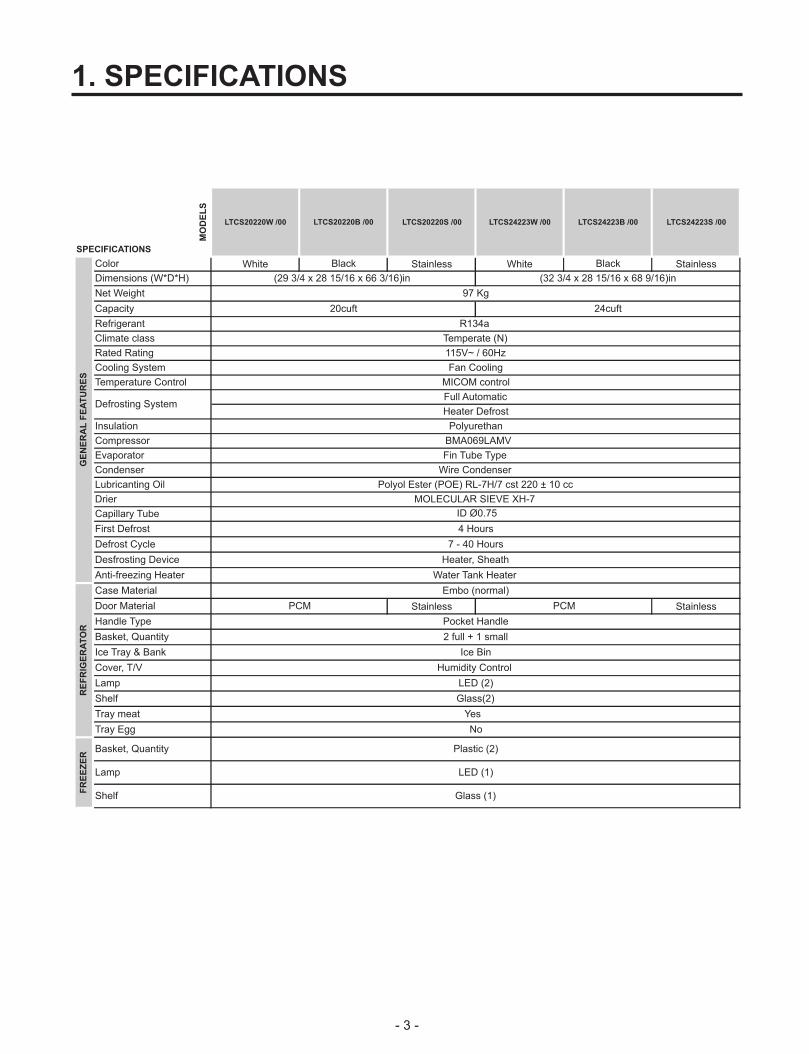
1. SPECIFICATIONS
LTCS20220W /00 LTCS20220B /00 LTCS20220S /00 LTCS24223W /00 LTCS24223B /00 LTCS24223S /00
White Black Stainless White Black Stainless
Stainless Stainless
(29 3/4 x 28 15/16 x 66 3/16)in (32 3/4 x 28 15/16 x 68 9/16)in
20cuft 24cuft
R134a
Temperate (N)
Pocket Handle
97 Kg
Ice Bin
Humidity Control
LED (2)
Glass(2)
Heater, Sheath
Water Tank Heater
Embo (normal)
PCM
Wire Condenser
Polyol Ester (POE) RL-7H/7 cst 220 ± 10 cc
MOLECULAR SIEVE XH-7
ID Ø0.75
MICOM control
Full Automatic
Heater Defrost
Polyurethan
2 full + 1 small
Yes
No
Plastic (2)
LED (1)
Glass (1)
7 - 40 Hours
PCM
Fin Tube Type
4 Hours
Fan Cooling
BMA069LAMV
115V~ / 60Hz
Climate class
MO
DE
LS
SPECIFICATIONS
Capacity
Refrigerant
Net Weight
Dimensions (W*D*H)
GE
NE
RA
L F
EA
TU
RE
S
Color
Anti-freezing Heater
Cooling System
Rated Rating
Insulation
Compressor
Temperature Control
Defrosting System
Evaporator
Capillary Tube
First Defrost
Condenser
Lubricanting Oil
Drier
RE
FR
IGE
RA
TO
R
Case Material
Door Material
Handle Type
Basket, Quantity
Defrost Cycle
Desfrosting Device
FR
EE
ZE
R
Basket, Quantity
Tray meat
Ice Tray & Bank
Cover, T/V
Lamp
Shelf
Tray Egg
Lamp
Shelf

2. PARTS IDENTIFICATION
- 4 -
Use this section to become more familiar with the parts and features.
NOTE: This guide covers several diferent models. The refrigerator you have purchased may have some
or all of the items listed below. The locations of the features shown below may not match your model.
Custom Cube Icemaker *
Ice Bin
Ice Tray *
Freezer Shelf
Freezer Temperature Control
Refrigerator Temperature Control
Shelves
Refrigerator Light (LED)
Pantry Drawer
Crispers
Freezer light (LED)Freezer Door Bins
* On some models
A
B
C
D
E
F
G
H
J
K
L
I
Dairy BinM
A O
B
C
D
E
F
G
H
L
NI
J
M
K
Refrigerator Door BinsN
F. Deco DuctN

- 5 -
3. DISASSEMBLY
Middle Hinge Bracket
Fig. 4
Fig. 5
Fig. 6
TOOLS NEEDED
REMOVING THE FREEZER DOOR
REMOVING THE REFRIGERATOR DOOR
Fig. 1
Fig. 2
Hinge Pin
Middle Hinge Bracket
Fig. 3
• 10mm or 13/32 -inch socket wrench• (with 2-inch extension for bottom door hinge)• No. 2 Phillips head screwdriver• Flat-head screwdriver for prying• Adjustable wrench
Remove the top-hinge cover by gently prying it with a flat head screwdriver.
Loosen and remove the two bolts using a phillips head screwdriver.
Remove the middle hinge bracket.
Carefully lift up the door. Place the door on a non scratching surface.
Using either a 10 mm or 13/32 in. socket wrench, remove the three bolts and lift off the top hinge. Set parts aside.
Carefully lift up the freezer door. Place the door on a non- scratching surface.
WARNING WARNINGExcessive Weight Hazard:
Use two or more people to remove and install therefrigerator doors. Failure to do so can result in back orother injury.
Electrical Shock Hazard
• Disconnect the electrical supply to the refrigeratorbefore installing. Failure to do so could result inserious injury or death.• Do not put hands, feet or other objects into the airvents, base grille, or bottom of the refrigerator. Youmay be injured or receive an electrical shock.

- 6 -
REPLACING THE REFRIGERATOR DOOR
REPLACING THE FREEZER DOOR
Fig. 7
Fig. 8
Fig. 9
Fig. 10
Lower the door onto the bottom hinge pin.Place the hinge pin of the middle hinge bracket inside of the hinge pin insert on top of the door. Hold the door in place and line the middle hinge bracket with the holes in the refrigerator housing.
Use the two bolts and phillips screwdriver to refasten the middle hinge bracket and door to the refrigerator housing.
Set the freezer door onto the Middle Hinge pin.
Place the upper hinge pin in the top of the freezer door and line up the upper hinge with the holes on top of the refrigerator. Use the three bolts to replace the hinge.
Carefully force-fit the top hinge cover back into place over the hinge.
Fig. 11
REVERSING DOORS
CAUTIONRemove food and any Adjustable Shelves or Door Bins from doors. Failure to do so could result in serious injury.
TOOLS NEEDED• 10mm or 13/32 inch socket wrench (with 2-inchextension for bottom door hinge)• No. 2 Phillips head screwdriver• 1/4 inch socket wrench• Flat-head screwdriver for prying• Adjustable wrench• 3/32 - inch hex wrench
REVERSING THE FREEZER DOOR
Gently pry off the top hinge cover with a flat headscrewdriver and remove.
Using 10mm or 13/32 inch socket wrench, remove the three bolts and lift off the top hinge. Set parts aside.
Fig. 17
Top Hinge
Fig. 18

- 7 -
Slightly lift up the refrigerator door and remove it.
Turn the freezer door upside down on a non-scratch surface.Loosen the screw to remove the Door Closer/Stop and Hinge Pin Insert.
Move the Hinge Pin Insert Bracket to the other side of the door, keeping the same orientation, and move the Hinge Pin Insert into the hole on the left side of the bracket.
Reverse the Door Closer/Stop by flipping it over. Place it on top of the Hinge Pin Insert Bracket, and tighten both down with the screw.
Middle Hinge Bracket
Hinge PinFig. 19
Door Closer / Stop
Fig. 20
Hinge Pin Insert Bracket
Hinge Pin Insert
Fig. 21
Fig. 22
Pry off the cover on the top left side of the refrigerator to uncover the screw holes.Set the freezer door and top hinge parts to the side and remove the refrigerator door.
REVERSING THE REFRIGERATOR DOOR
Using a ¼” socket wrench, loosen and remove Hinge Pin from the Middle Hinge Bracket. Remove washer underneath the middle hinge and set aside.NOTE: At this point the door will be loose. Slightly lift the door and remove it.
Cover (on top of refrigerator)
Fig. 23
Fig. 29
Fig. 30

- 8 -
Loosen and remove the two bolts and use the Phillips head screwdriver to remove the Middle Hinge Bracket from the refrigerator housing. Set parts aside.
Remove the washer from the Bottom Hinge Pin.Using a ¼” socket wrench, loosen and remove the Hinge Pin from the Bottom Hinge. Reattach the Hinge Pin to the opposite side of the hinge.
NOTE: This is easier to do while the hinge is still attached.
Using a 13/32’’ socket wrench with a 2-Inch extension and screwdriver, loosen the two bolts and one screw, and remove the Bottom Hinge from right side of the housing.
Fig. 31
Fig. 33
Fig. 32
Remove the Decorative Caps on the bottom of therefrigerator housing. You will need these holes for the Bottom Hinge.
Move the Bottom Hinge to the left side of the housing,keeping the same orientation, and reattach with the two bolts and one screw. The flat screw must be placed on the exterior side of the hinge. Move the Decorative Bolt to the hole on the lower right side of the housing.
Turn the refrigerator door upside down on a nonscratching surface. Loosen the two screws to remove the Bottom Hinge Pin Bracket with the Hinge Pin Insert.
Take out the Hinge Pin Insert and move the Bracket to the other side of the door, keeping the same orientation.Place the Hinge Pin Insert into the left side of the bracket.Tighten the Hinge Pin Bracket to the door.
Fig. 34
Fig. 35
Fig. 36
Hinge Pin BracketHinge Pin Insert
Fig. 37
Hinge Pin Bracket
Hinge Pin Insert
Fig. 38

- 9 -
With a flat-head screwdriver, carefully pry off andremove the cover over the screw holes on the left side of refrigerator housing.
Remove the outer lower Decorative Screw from thehousing at the area between the freezer and refrigerator doors. (You will need this hole for the Middle Hinge Bracket).
Flip the Middle Hinge Bracket, (flange will now be on top) position it on left side of the refrigerator and reattach with two bolts and a Phillips screwdriver. Place the refrigerator door down over the pin on the bottom hinge.Place the washer between the refrigerator door andmiddle hinge and re-attach Hinge Pin to Hinge Bracket with a ¼” socket wrench.
NOTE: Bracket has been flipped, but Hinge Pin stays in the same orientation with its hexagonal end facing upward.
Insert the Decorative Screw into the outer hole on the right side of the housing. Attach cover on the right side. Cover is force-fitted.
Fig. 39
Fig. 40
Middle HingeBracket
Flange
Fig. 41
REATTACHING THE DOORSPlace the freezer door down over the Hinge Pin on the Middle Hinge Pin Bracket.
Place the Upper Hinge Pin on top of the freezer door and line up the Upper Hinge with holes on top of the refrigerator. Use the three bolts to replace the Hinge.
Tighten the bolts. Force-fit Top Hinge Cover over Top Hinge.
Replace cover on the top left side of the refrigerator to the right top to cover the holes. Cover is also force-fitted.
Decorative Screw
Fig. 42
Fig. 43
Fig. 44
Fig. 45
Cover (on top of refrigerator)
Fig. 46

- 10 -
After changing the doors, make sure that the corners of the Door Gaskets are not folded over. To ensure a good seal, apply a small amount of silicon grease on the corners of gaskets.
CLOSING AND ALIGNING THE DOORS To avoid vibration, the unit must be leveled. If necessary, adjust the Leveling Legs to compensate for unevenness of the floor. The front should be slightly higher than the rear to aid in door closing. Your refrigerator has three front leveling screws, one on the right and one on the left. If your refrigerator seems unstable or if you would like the doors to close more easily, simply adjust the inclination of the refrigerator by following the instructions below:
NOTE: Third leveling screw is used for protection of hinge lower.
1. Plug the refrigerator into a 3 prong grounded outlet. Move the refrigerator into its final position.
2. Use a flat head screwdriver to adjust the leveling screws (see Figure A), turning clockwise to raise the side of the refrigerator and counter-clockwise to lower it. It may take several turns to adjust it to the inclination you would like. NOTE: Having someone push against the top of the refrigerator takes some weight off the leveling screws. This will make it easier to adjust the screws.
3. Open both doors again and check to make sure that they close easily. If not, tilt the refrigerator slightly more to the rear by turning both Leveling Screws clockwise. It may take several more turns, and you should turn both Leveling Screws the same times.
CornersFig. 53
DOOR ALIGNMENTIf the space between your doors is uneven, follow the instructions below to align the doors.1. Gently pry off the refrigerator door Top Hinge Cover with a flat head screwdriver and remove. Loosen the Top Hinge Bolts using a 10mm or 13/32’’Socket wrench or open-end wrench.2. Have a second person hold the refrigerator door in its proper position.3. Replace the Top Hinge Cover.
3-9 FAN AND FAN MOTOR1. Remove the freezer shelf. (If your refrigerator has an icemaker, unplug and remove the icemaker first).2. Remove the screw of the grille fan.3. Remove the grille by pulling it out.4. Remove the Fan Motor assembly by loosening 4 screws and disassemble the shroud.5. Pull out the fan and separate the Fan Motor and Bracket.
SHROUD
GRILLE
FAN MOTOR
Fig. 40
FAN
BRACKET

- 11 -
Fig. 44
3-12 CONTROL BOX-REFRIGERATOR1. First, remove all shelves in the refrigerator. Then remove the Refrigerator Control Box by loosening 2 screws.
2. Remove the Refrigerator Control Box by pulling it downward.3. Disconnect the lead wire on the left position.
Fig. 43
LED
3-10 DEFROST CONTROL ASSEMBLYDefrost Control assembly consists of Defrost Sensor and FUSE–M.Defrost sensor functions to defrost automatically. It is attached to metal side of the Evaporator and senses Temperature. At the temperature of 162°F(72°C), it stops the emission of heat from the Heater.Fuse-M is a safety device for preventing over-heating of the Heater when defrosting.1. Pull out the grille assembly. (Figure 41).2. Separate the connector of the Defrost Control assembly and replace the Defrost Control assembly after cutting the Tie Wrap. (Figure 42)
3-11 LIGHTS
3-11-1 Freezer Compartment Light(Top)1. Unplug the power cord from the outlet.2. Put a flat screwdriver into service hole and remove the cover of Freezer light.3. Remove the LED assembly from connector.4. Replace the LED assembly.5. Assemble in reverse order of disassembly.
3-11-2 Refrigerator Compartment Light(Side)1. Unplug the power cord from the outlet.2. Put a flat screwdriver into service hole and remove the cover of Refrigerator light.3. Remove the LED assembly from the connector.4. Replace the LED assembly.5. Assemble in reverse order of disassembly.
GRILLE ASSEMBLY DEFROST-CONTROLASSEMBLY
Fig. 42Fig. 41

4-2-3 PTC - Applied Circuit DiagramStarting Method for the Motor
4. COMPRESSOR ELECTRICAL4-1 COMPRESSOR
4-1-1 Role
The compressor intakes low temperature and low pressure gas from the evaporator of the refrigerator and compresses this gas to high temperature and high pressure gas. It then delivers the gas to the condenser.
4-1-2 Composition
The compressor includes overload protection. The PTC starter and OLP (overload protector) are attached to the outside of the compressor. Since the compressor is manufactured to tolerances of 1 micron and is hermetically sealed in a dust and moisture-free environment, use extreme caution when repairing it.
4-1-3 Note for Usage
(1) Be careful not to allow over-current.(2) If compressor is dropped or handled carelessly, poor operation and noise may result.(3) Use proper electric components appropriate to the particular compressor in your product.(4) Keep compressor dry.If the compressor gets wet (in the rain or a damp environment) and rust forms in the pin of the Hermetic Terminal, poor operation and contact may result. If the hermetic connector rusts out or fails, refrigerant and oil will be expelled into the contact area, probably resulting in smoke and fire.(5) When replacing the compressor, be careful that dust, humidity, and soldering flux don´t contaminate the inside of the compressor. Contamination in the cylinder may cause noise, improper operation or even cause it to lock up.
4-2 PTC-STARTER4-2-1 Composition of PTC- Starter
(1) PTC (Positive Temperature Coefficient) is a no-contact semiconductor starting device which uses ceramic material consisting of BaTiO3.(2) The higher the temperature is, the higher the resistance value. These features are used as a starting device for the motor.
4-2-2 Role of PTC-Starter
(1) The PTC is attached to the Sealed Compressor and is used for starting the motor.(2) The compressor is a single-phase induction motor. During the starting operation, the PTC allows current flow to both the start winding and main winding.
COMPRESSOR ACCESORIES
PTC DIAGRAM
- 12 -
PK
CAPACITOR PART
2
3
5
P.T.C
6
Cr
BL
BK
BL
OLP
PART
COMP' EARTH
GN
(GN)/YL
M
S
LF, MQ COMP' (e - PTC)
* P.T.C OPTION
3
2 5
6
4-2-6 Motor Restarting and PTC
(1) It requires approximately 5 minutes for the pressure to equalize before the compressor can restart.(2) The PTC device generates heat during operation. Therefore, it must be allowed to cool before the compressor can restart.
4-2-7 Relation of PTC-Starter
(1) If the compressor attempts to restart before the PTC device is cooled, the PTC device will allow current to flow only to the main winding.(2) The OLP will open because of the over current condition. This same process will continue (3 to 5 times) when the compressor attempts to restart until the PTC device has cooled. The correct OLP must be properly attached to prevent damage to the compressor.Parts may appear physically identical but could have different electrical ratings. Replace parts by part number and model number. Using an incorrect part could result in damage to the product, fire, injury, or possibly death.

4-2-8 Note for using the PTC-Starter
(1) Be careful not to allow over-voltage and over-current(2) Do not drop or handle carelessly.(3) Keep away from any liquid.If liquid such as oil or water enters the PTC, PTC materials may fail due to breakdown of their insulating capabilities.(4) If the exterior of the PTC is damaged, the resistance value may be altered. This can cause damage to the compressor and result in a no-start or hard-to-start condition.(5) Always use the PTC designed for the compressor and make sure it is properly attached to the compressor. Parts may appear physically identical but could have different electrical ratings. Replace parts by part number and model number. Using an incorrect part could result in damage to the product, fire, injury, or possibly death.
Customer partnumber
Lot code/date code330 FBYY -S1 BOX98
12345678
Physicalterminationpart number
Electricalcharacteristics
part number
(OVERLOAD PROTECTOR cross section)
Fig. 45
4-3 OLP (OVERLOAD PROTECTOR)
4-3-1 Definition of OLP
(1) OLP (OVERLOAD PROTECTOR) is attached to the compressor and protects the motor by opening the circuit to the motor if the temperature rises activating the bimetal spring in the OLP.(2) When high current flows to the compressor motor, the bimetal works by heating the heater inside the OLP, and the OLP protects the motor by cutting off the current flowing to the compressor motor.
4-3-2 Role of the OLP
(1) The OLP is attached to the sealed compressor used for the refrigerator. It prevents the motor coil from being started in the compressor.(2) For normal operation of the OLP, do not turn the adjust screw of the OLP in anyway.
- 13 -

5. CIRCUIT DIAGRAM
- 14 -

6. TROUBLESHOOTING
- 15 -
6-1 COMPRESSOR AND ELECTRIC COMPONENTS
1
2
3
4
5
2
5
5
3
5
1
43
YES
NO
YES
Open or short
YES YES
NO
NO
Power Source.
No voltage.
(Rated voltage±10%)?
Replace OLP.
Reconnect.
Didcompressorstart?
Compressoris OK
Replace thecompressor
Check connectioncondition.
OLP disconnected?
Advise customer thatpower supply needs to bechecked by an electrician.
Supplyvoltage ratingwith ±10%.
Applied voltage isn'tin acceptable range.(115V ±10%)
Remove PTC-Starterfrom compressor andmeasure voltagebetween Terminal C ofcompressor andterminal 5 or 6 of PTC
Check resistance of
PTC-Starter
Check resistance of twoterminals in OLP.
Check the power supplyunder load.(Compressor attemptingto re-start after being offfor 5 minutes).
.
Checkresistance ofPTC-Starter.
Check OLP.
Checkstarting state.
Check resistance of motor compressor. Replace
compressor
Check resistance of motor compressor.
The resistance between pins should be between 1 and 50 ohms. The resistance to ground should be infinite.
or short to ground
Check the resistance between M-C, S-C and M-S in motor compressor.Check each pin to ground.
Check resistance oftwo terminals in PTC-Starter
At normal temperature6.8 +20: OK?
If power conducts: OKIf not: NG

- 16 -
6-2 PTC AND OLP
6 5
Shows continuity
Open
Separate PTC-Starterfrom Compressor andmeasure resistancebetween No. 5 and 6
of PTC-Starter with aTester.(Figure 1)
Observation value is115V/60Hz : 6.8? ±20%
The resistance valueis 0 ? (short) or
Check anotherelectric component.
Replace OLP.
Replace PTC-Starter.
Figure 1 Figure 2
Normal operation of compressor is impossible or poor.
Separate OLP from compressor and check resistance value between two terminals of OLP whit a tester.(Figure 2)
?
at room temperature 25 c
8.2 ? at 25 c

- 17 -
• Not cooling at all
• Poor cooling performance
Compressordoesn't run.
Compressor runspoorly.
Check a startingvoltage.
Check for open short orincorrect resistance readingsin the following components
a. Starting devices
b. OLP
c. Compressor coil
d.Wiring harness
Low voltage.
Short, open or broken.
Poor contact or shorted.
Coil open or shorted.
Poor contact or shorted.
Poor or broken oropen contact.
Shorted.
Lack of capacity.
Replaceindicated component.
Raise voltage.
Replaceindicated component.
Cause
Check voltage atstarting devices.
Check current atCompressor.
Check rating of OLP.
Fan motordoesn't run.
Heavy frost buildup onEVAPORATOR.
Wire is open orshorted.
Coil is shorted oropen.
Open.
Open.ReplaceDefrost Heater.
Replaceindicated component.
Replaceindicated component.
Check wiring circuit.
Check Fan Motor.
Check current flow inthe followingcomponents:- Sensor- Fuse-M
Check current flow inthe Defrost Heater.
6-3 OTHER ELECTRIC COMPONENTS

6-4 SERVICE DIAGNOSIS CHART
- 18 -
COMPLAINT SYMPTOM POSSIBLE CAUSES SOLUTION
1. Supply voltage not within specifications 1. Check supply voltage to refrigerator
2. Open in wiring harness from PWB board 2. Chack wiring and connectors to PWB board
3. Open in door monitor switch circuit 3. Check door monitor circuit
1. Supply voltage not within specifications 1. Check supply voltage to refrigerator
2. Open wiring harness from PWB board 2. Chack wiring and connectors to PWB board
1. Compressor not operating 1. Check for compressor operation by using the test key on main circuit board.
2. Open in compressor circuit 2. Check for open on OLP, PTC, compressor, wiring.
1. Condenser fan motor not operating 1. Check condenser fan motor and wiring circuit
2. Condenser coils blocked 2. Check air flow across condenser
3. Evaporator fan motor not operating 3. Check evaporator fan motor and wiring circuit
4. Internal air flow blocked 4. Check air ducts
5. Sensor not operating properly 5. Check refrigerator and freezer sensors
6. Door not sealing 6. Check for proper door seal
7. Evaporator frosted up 7. Check defrost circuit components
8. Sealed system related problem
1. Open in defrost circuit 1. Check defrost heater and circuit using Test Key
2. Defrost sensor not operating correctly 2. Check sensor
3. Defrost drain clogged 3. Check drain
1. Freezer has toomuch frost
1. Display on compressor is operating
1. No Display at all
2. Partial or abnormal display
1. Display on but compressor not operating
Electronic Display not operating correctly
Not cooling
Not cold enough
Not defrosting

6-5 REFRIGERATING CYCLE
- 19 -
• Troubleshooting Chart
Leakage Detection
PARTIAL Freezer Low flowing sound of A little higher • Refrigerant level is low due LEAKAGE compartment and Refrigerant is heard and than ambient to a leak.
Refrigerator don't frost forms in inlet only. temperature. • Normal cooling is possible by cool normally. restoring the normal amount of
• Refrigerant and repairing the leak.
COMPLETE Freezer Flowing sound of refrigerant Equal to ambient • No discharging of Refrigerant.LEAKAGE compartment and is not heard and frost isn't temperature. • Normal cooling is possible by
Refrigerator don't formed. restoring the normal amount of cool normally. refrigerant and repairing the leak.
PARTIAL Freezer Flowing sound of refrigerant A little higher • Normal discharging of theRESTRICTION compartment and is heard and frost forms than ambient refrigerant.
Refrigerator don't in inlet only. temperature. • The capillary tube is faulty.cool normally.
WHOLE Freezer Flowing sound of refrigerant Equal to ambient • Normal discharging of theRESTRICTION compartment and is not heard and frost isn't temperature. refrigerant.
Refrigerator don't cool. formed.
MOISTURE Cooling operation Flowing sound of refrigerant Lower than • Cooling operation restartsRESTRICTION stops periodically. is not heard and frost melts. ambient when heating the inlet of the
temperature. capillary tube.
COMP- Freezer and Low flowing sound of A little higher • Low pressure at high side RESSION Refrigerator refrigerant is heard and ambient of compressor due to low
don't cool. frost forms in inlet only. temperature. refrigerant level.
NO COMP- No compressing Flowing sound of refrigerant Equal to ambient • No pressure in the high RESSION operation. is not heard and there is temperature. pressure part of the
no frost. compressor.
CAUSETEMPERATURE
OF THECOMPRESSOR
REMARKSSTATE OFTHE UNIT
STATE OF THEEVAPORATOR
LE
AK
AG
ER
ES
TR
ICT
ION
DE
FE
CT
IVE
CO
MP
RE
SS
ION
Check sealed system for leak.
Check if compressor runs.(If don’t , wait a while until it start to work)
YES Check frost pattern on Evaporator. (Eva In, Eva Out)
If frost is formed normally
Only check that there is not anyhole or bad welding in Eva in-Eva out.
No frost or frost formsin inlet only
Check for oil leak on highside (Machinery Room)
Gas leakage
Repair it.
YES
Confirm refrigerant amount
None or too much.
Recharge refrigerant(check correct quantity)
Finished OK
Frost formed normally
Moisture restriction. intermittent problem.
Replace Compressor
FaultyCompressor
Normal Amount
Restriction
No frost normally
Frost formed normally

7-1 OPERATION PRINCIPLE
7-1-1 Operation Principle of Icemaker
1. Turning the Icemaker stop switch off (O) stops the icemaking function.
2. Setting the Icemaker switch to OFF and then turning it back on will reset the icemaker control.
Power (On/Off) Switch
Water amount control button
Start Position
IcemakingMode
HarvestMode
Park Position
Fill
•
Test Mode
Waits until water becomes cold after starting the Icemaking operation.
• Runs MOTOR to drop ice from the tray into the ICE BIN.
• Performs Icemaking Mode after supplying water by operating the SOLENOID in ICE VALVE.
• To operate LINE and SERVICE, insert pin at hole . located at front, press internal button and hold 3 seconds
Harvest Fill Icemaking.
• With the detect lever, checks if the ICE BIN is full.
Power On
• Adjusts Ejector to Start Position whit power on.
- 20 -
7. ICE MAKEROPERATION PRINCIPLE AND REPAIR METHOD OF ICEMAKER
The icemaking will run through 3 stages:

7-2 ICEMAKER FUNCTIONS
7-2-1 Start Position
1. After POWER OFF or Power Outage, check the EJECTOR's position with MICOM initialization to restart.
2. How to check if it is in place:
- Check HIGH/LOW signals from HALL SENSOR in MICOM PIN.
3. Control Method to check if it is in place:
(1) EJECTOR is in place,
- It is an initialized control, so the mode can be changed to icemaking control.
(2) EJECTOR isn't in place:
A. If EJECTOR is back in place within 2 minutes with the motor on, it is being initialized. If not, go to Step B.
B. If EJECTOR is back in place within 18 minutes after the heater turns from ON to OFF, it is being initialized. If not, it is
not functioning. Repeat Step B with Heater and Motor off.
7-2-2 Icemaking Mode
1. Icemaking refers to the freezing of supplied water in the ice trays. Complete freezing is assured by measuring the
temperature of the Tray with Icemaking SENSOR.
2. Icemaking starts after completion of the water fill operation.
3. The Icemaking function is completed when the sensor reaches -7°C, 60 to 240 minutes after starting.
4. If the temperature sensor is defective, the ice-making function will be completed in 4 hours.
NOTE :After icemaker power is ON, the icemaker heater will be on for test for 9 seconds.
7-2-3 Harvest Mode
1. Harvest (Ice removing) refers to the operation of dropping cubes into the ice bin from the tray when icemaking has
Completed.
2. Harvest mode:
(1) The heater is ON for 30 seconds, then the motor starts.
(2) After performing Step 1 (the heater is turned OFF), the ejector will be back in place wthin 18 minutes. (Hall sensor
sign = OV). Ice removal is then complete. Then the icemaker cycles to the fill mode. The water supply fails to start, it
is not functioning. Put the heater and motor in the off position. Restart every 2 hours. (Refer to figure1)
NOTE :If the motor malfunctions and starts before the detect lever rises, MICOM regards the Ice-Removing phase as
completed. Water then starts flowing. To prevent this, MICOM doesn’t switch to water-supply mode, but restarts the ice-
removing mode. If this happens 3 times, the motor is malfunctioning and you should stop the loads (heater, motor). Then
restart the Ice-Removing mode every 2 hours. (See Step 2 above.)
- 21 -
on
Heateroff
on
0V
5V
off
30 sec.
10 sec.
Motor
Hall IC
Ice removingcompletion point
2 ms
Icemaking sensor temperature is 10ºC or more Maximum 18 minutesAfter detect LEVER rises
Figure1. Harvest mode Process

- 22 -
7-2-4 Fill/Park Position
1. Once a normal harvest mode has been completed, the water solenoid will be activated.
2. The amount of water is adjusted by inserting a “pin” into small hole located at front of ice maker. These changes
the time allowed for fill as illustrated in the table below.
Water supply amount TABLE
STAGE TIME TO SUPPLY INDICATIONS REMARKS
1
2
3
6 sec.
7 sec.
8 sec.
The water amount will vary depending
on the water control switch setting, as
well as the water pressure of the
connected water line.
NOTE :Below is an example used by another vendor as an explanation of what is taking place.
NOTE: The water mount only must be changed by technicians.

- 23 -
7-2-5 Function TEST
1. This is a compulsory operation for test, service, cleaning, etc,. Insert pin pressing internal button.
2. The test works only in the Icemaking Mode. It cannot be entered from the Harvest or Fill mode. (If there is an ERROR, it
can only be checked in the TEST mode.)
3. Caution! If the test is performed before water in the icemaker is frozen, the ejector will pass through the water. When the fill
mode begins (Stage 4), unless the water supply has been shut off, added water will overflow into the ice bin. If the control
Doesn’t operate normally in the TEST mode, check and repair as needed.
4. After water is supplied, the normal CYCLE is followed: icemaking Harvest Fill Park Position.
5. Five seconds after Stage 5 is completed, the icemaker returns to MICOM control. The time needed to supply water
resets to the pre- test setting.
Diagnosis TABLE
7-3 DEFECT DIAGNOSIS FUNCTION
7-3-1 ERROR CODES shown on Ice Maker water supply control panel
ERROR indicators in table can be checked only in TEST mode.
STAGE ITEMS INDICATOR REMARKS
1
2
3
4
5
6
HEATER
MOTOR
HALL IC
(TRAY)
SOLENOID VALVE
HALL IC
(LEVER)
Reset
Five seconds after heater starts, heater will
go off if temperature recorded by sensor is
10°C or lever is in up position.
Five seconds after heater starts, you can
confirm that motor is moving.
You can confirm Hall IC detection of position.
Two seconds after detection of initial
position, you can confirm that valve is on.
You can check when the Hall IC is sensing a full
ice condition. (If there is a water fill error, the
fifth LED is not on.)
Five seconds after fifth stage is completed,
the icemaker resets to initial status.Return to Status prior to
TEST MODE
NO DIVISION INDICATOR CONTENTS REMARKS
1
2
3
Normal
IcemakingSensor
malfunction
Icemaker Kitmalfunction
Mark time tosupply None
Open or short-circuited wire
When ejector blades don´t reachpark position over 18 minutes after
harvest mode starts.
Display switch operates properly
Make sure that the wireon each sensor is
connected.
Check HALL IC/MOTOR/HEATER/RELAY

- 24 -
8-1 FUNCTION
8-1-1 Function
1. When the appliance is plugged in, is set to middle for the refrigerator. You can adjust the Refrigerator control temperature by pressing the TEMPERATURE ADJUST button.
2. When the power is initially applied or restored after a power failure, it is set at the last control temperature selected before
8-1-2 Defrost Cycle
Defrosting starts each time the accumulated COMPRESSOR running time is between 7 and 50 hours. This time is determinate by how long the doors are opened.For initial power on or for restoring power, defrosting starts when the compressor running time reaches 4 hours.Defrosting stops if the sensor temperature reaches 50 °F (10 °C) or more. If the sensor doesn’t reach the 50 °F (10°C) in 1 hour, the defrost mode is malfunctioning. (Refer to the defect diagnosis function).Defrosting won’t function if the sensor if defective (wires are cut or short circuited)
8-1-3 Electrical Parts Operation in Sequence.
Electrical parts such as COMP, defrost heater, freezer FAN, etc. Operate in the following order to prevent noise and parts damage. Several parts are started at the same time at initial power on and are turned off together when TEST is completed.
OPERATING ORDER REMARKS
INIT
IAL
PO
WE
R O
N
Temperature of defrostsensor is 113°F (45°C) or more .
Temperature of defrostsensor is lower than113°F (45°C)
POWER ON
COMP,F-FAN
ON
0.5 Se
c
POWER ON
Def-Heater
ON
Def-Heater
OFF
0.5Sec
10 Sec
0.5 Sec COMP,F-FAN
ON
OPERATING ORDER REMARKS
INIT
IAL
PO
WE
R O
N
Temperature of defrostsensor is 113°F (45°C) or
Temperature of defrostsensor is lower than113°F (45°C .
POWER ON
COMP,F-FAN
ON
0.5 Se
c
POWER ON
Def-Heater
ON
Def-Heater
OFF
0.5Sec
10 Sec
0.5 Sec COMP,F-FAN
ON
the power initially applied or restored a power failure.
8. CIRCUIT OF MICOMDESCRIPTION OF FUNCTION & CIRCUIT OF MICOM

8-1-4 Defect Diagnosis Function
1. If there is a problem, an error code will appear..2. The buttons will not operate.3. When the problem is repaired, the display will return to normal.4. The error code is displayed using the LEDs.
• ERROR CODE on Refrigerator Temperature panel
- 27 -
NO ItemError Code
ContentsProduct Operation Status in Failure
CompressorFreezer Motor
DefrostHeaterR1 R2 R3 R4 R5
1Failure of Refrigerator . Sensor Ref. Sensor Open or
Short circuit wire
15min ON/15 min OFF
15min ON/15 min
OFFNormal
2Failure of Defrost Sensor Defrost Sensor Open
or Short circuit wireNormal Normal
No defrost
3Failure of Room Temperature Sensor
RT Sensor Open or Short circuit wire
Normal Normal Normal
4Failure of Defrost mode
When defrosting
sensor do not reach reach 50 °F (10 ? )
within 1Hr after
starting Defrost
Normal Normal Normal
5Failure of Fan Motor at freezer Compartment
If there is not motor Signal (motor could be
locked)
Normal OFF Normal
- 25 -
ON OFF

8-1-5 TEST MODE
1. Test mode allows checking the PCB and the function of the product as well as determining the Defective part in case of an error.
2. The test button is on the main PCB of the refrigerator (Test S/W).3 While in the test mode, the “Temperature Adjust” button will not operate.4. After exiting the test mode, be sure to reset by unplugging and plugging in the appliance5. If an error, such as a sensor failure is detected while in the test mode, the test mode is cleared and the error code is displayed 6. While an error code is displayed, the test mode will not be activated.
Demonstration MODE (OFF)
1. Press the Temperature Adjust button untill the OFF LED turns ON to activate this mode (After selecting theDemonstration Mode it takes 10 seconds to be enable).2. In this Status all loads are OFF (compressor, fans, heaters) only LED lamp will be in normal function.3. To exit of the Demonstration Mode press the Temperature Adjust button and set the desired temperaturelevel. The device will reset after 10 seconds and the display will blink one time
Note: If door is opened within the first 5 minutes from power on the demonstration mode, it will be released and set at middle level automatically.
- 26 -
- 28 -
MODE Key Control Operation Remarks
TEST1Test Button
Pushed 1 Time<Pull Down Mode>
1) Comp, FFAN and CFAN.
2) Defrosting heater OFF
3) All Display ON* The maximum time for TEST1
is 5 min
TEST2
Test ButtonPushed again after
Test Mode1<Defrosting Mode>
1) Comp, FFAN and CFAN.
2) Defrosting heater ON
3) Display LED →as belows
ReturnTo normalcondition
Test ButtonPushed again after
Test Mode2
Return to normal state (Compressor will delay 7 minutes
to power ON
Operate max 1Hr
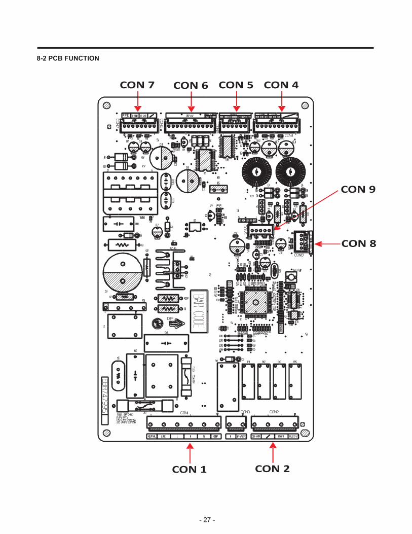
8-2 PCB FUNCTION
- 27 -
CON 1 CON 2
CON 4CON 5CON 6CON 7
CON 8
CON 9

8-2-1 Power Circuit
Power is supplied to the control board at the pin 11 and 9 of connector #1. (Refer to figure 1)
FIGURE 1
8-2-2 Load and Door Light Circuit (HV)
1. Load Drive Condition CheckTo measure outputs of the control board, check voltages between the pins for the following components:(Refer to figure 1)
- 28 -
CONNECTOR 1
PIN 11 9 7 5 3 1
NEUTRAL LIVE L (I/M) N (I/M) N COMP
CircuitPin
NumberPin
NumberOutputVoltage
Compressor Con 1 Pin 1 Con 1 Pin 3 115 VAC
Defrost Heater Con 2 Pin 7 Con 1 Pin 3 115 VAC
Ice Maker Con 1 Pin 7 Con 1 Pin 3 115 VAC
Pilot Valve Con 2 Pin 1 Con 1 Pin 3 115 VAC
CONNECTOR 2
PIN 7 5 3 1
DEF-HTR / R-HTR PILOT/V
2. Door Monitor Circuit (LV)
RefrigeratorMeasurement between
pins 4 and 3 Con 8
Door Close 0 volts PIN 1 2 3 4Door Open 5 volts RT-SNR R-DOOR S/W
CONNECTOR 8

- 29 -
PIN 1 2 3 4 5 6 7 8 PIN 1 2 3 4
N/C N/C N/C N/C
CONNECTOR 8
RT-SNR R-DOOR S/WD-SNR R-SNR
CONNECTOR 7
To measure the outputs of the sensors, check the voltages between the pins as in the table. And refer the values in the section “RESISTANCE SPECIFICATION OF SENSOR”
SENSOR Pin Number Pin Number
D-SNR Con 7 Pin 3 Con 7 Pin 4
R-SNR Con 7 Pin 5 Con 7 Pin 6RT-SNR Con 8 Pin 1 Con 8 Pin 2
3. LED Power Circuit (LV)
Circuit Pin Number Pin NumberOutputVoltage
LED Power Con 6 Pin 10 Con 6 Pin 11 12 VDC
CONNECTOR 6
PIN 1 2 3 4 5 6 7 8 9 10 11
DISPLAY 12V GND
volts indicates an open in the sensor circuit.temperature in the compartments. A measurement of 0 volts indicates a short in the sensor circuit. A measurement of 5 Voltage supplied to each sensor wil range between 0.5 volts -22°F(-30°C) and 4.5 volts 122°F(50°C) depending upon the
8-2-3 Temperature Sensor Circuit (Refer to figure 2)
FIGURE 2

- 30 -
8-3 RESISTANCE SPECIFICATION OF SENSOR
The resistance of the SENSOR has a ±5% common difference.Temperature of the SENSOR must be stabilized for minimum of 3 minutes before accurate measurement can be taken
• Measure the F-SENSOR, SUPER FROST SENSOR, R1, R2-SENSOR after disconnect CON5 of PWB AS
TEMPERATURERESISTANCE OF REFRIGERATOR &
DEFROST SENSORVOLTAGE
-20 °C (-4 °F) 77 3.73
-15 °C (5 °F) 60 3.49
-10 °C (14 °F) 47.3 3.22
-5 °C (23 °F) 38.4 2.95
0 °C (32 °F) 30 2.67
5 °C (41 °F) 24.1 2.4
10 °C (50 °F) 19.5 2.14
15 °C (59 °F) 15.9 1.89
20 °C (68 °F) 13 1.66
25 °C (77 °F) 11 1.46
30 °C (86 °F) 8.9 1.27
40 °C (104 °F) 6.2 0.96
50 °C (122 °F) 4.3 0.72
To measure the outputs of the fans on the control boards check the voltages between the pins for the following components:
MOTOR ON MOTOR OFF
Freezer Fan Con 4 pin 5 Con 4 pin 6 10 - 14 VCD 2 VCD or less
Cooling Fan Con 4 pin 2 Con 4 pin 3 10 - 14 VCD 2 VCD or less
FAN PIN NUMBER PIN NUMBEROUTPUT VOLTAGE
PIN 1 2 3 4 5 6 7 8 9 10
N/C G V F G V N/C N/C N/C N/C
C-FAN F-FAN N/C
CONNECTOR 4

309A
314A
307A
310A316A
316C
412D
312A
CASE PARTS CAUTION: Use the part number to order part, not the position number
103A
S01
103A
281A
281B
301A 401A
418A
282E501F
411A
S01
501A
304A
282B
S13406B
282H
402D
283B
120A
120A
120A120A
105A
318A
323B
420A
405G
405D
329C 319D
319F
106A
106A
#EV#
305B
305C
315A
305C305B
S01 S01
9. EXPLODED VIEW
317A
120A
120E
501B279A
120B
LD1
158B
LD1
LD3
158D
158C
404X
503G
410A
B01
S38
311A

FREEZER PARTSCAUTION: Use the part number to order part, not the position number
405C
404A
319E
330B
S01
332B
332A
284A
329A
110D
#EV#
405F
404Z
149F
S16

REFRIGERATOR PARTSCAUTION: Use the part number to order part, not the position number
167F
143F
143A
155F
#EV#
167B
170A
151A
151A
154A
151D
151C
155B

DOOR PARTSCAUTION: Use the part number to order part, not the position number
241A
230A
231A233A
281E
241C
241C
241D
286A
#EV#
205A
205A
200A
201A
203A212G
286A
210B
210C
210A

ICE MAKER PARTSCAUTION: Use the part number to order part, not the position number
131A
600A
602A
600C
619C
623A
627A
#EV#
S01
618A

May, 2015P/No. MFL31442314