lsj turbo kit instructions - amazon s3s3.amazonaws.com/zzpstorage/instructions/lsj+turbo+kit...lsj...
TRANSCRIPT

1
ZZPerformance ZZPerformance.com
Cobalt SS/SC Turbo Kit 2005-2007

Parts Description
TURBO PARTS: 252ext, .55 A/R, V-Band -4 to 12mm ecotec block fitting
-4 oil feed fitting for turbo
-4 oil feed line T3/T4 oil drain fitting
14” push loc drain hose
2

2 /.750 hose clamps
.625 barb fitting to .500npt
Alum. Weld-in bung for oil pan (.5npt)
EXHAUST PARTS: Ecotec T3 exhaust manifold
T3 gasket
3

3” V-band dp. (with or without re-circ)
3” V-band clamp
Atmosphere wastegate dump
Tial 38mm MVS Wastegate with .6bar spring
TURBO INTAKE PARTS: K&N air filter (part# 0950)
3.5” intake pipe
4

3” to 3.5” 90* coupler
Intake pipe mounting clamp
FUEL AND INTAKE PARTS: Modified Saab intake manifold
LSJ intake gasket
2.4L throttle body Throttle body adaptor harness
80lb injectors
5

Injector harness (EV1)
NGK 4644 spark plugs
INTERCOOLER PARTS: ZZP front mount intercooler
LSJ upper charge pipe with BOV flange
6

LSJ lower charge pipe with maf pad
BOV (ZZP or Tial) 2” to 2.5” silicone coupler
2.5” double 90* silicone coupler
2.5” 90* silicone coupler
2.5” to 2.75” 90* silicone coupler
7

CLAMPS: 1pc. 250 T-Bolt (turbo exit) 6pc. 288 T-Bolts 1pc. 325 T-Bolt (throttle body) 1pc. 3” hose clamp (turbo intake 90* coupler) 1pc. 3.5” hose clamp (turbo intake 90* coupler)
BOLTS AND HARDWARE: 7pc. 8*1.25mm*30mm (intake manifold to cyl. head)
7pc. 8mm flat washers (intake manifold to cyl. head)
3pc. 8mm*1.25*100mm (alternator)
4pc. 6*1.00mm*20mm (throttle body) 2pc. 6*1.00mm*13mm (map sensor, and boost control bracket)
4pc. 6*1.00mm*25mm (ic brackets in bumper)
8

2pc. 4*.70mm (for maf sensor)
4pc. 3/8-16 grade 8, *25mm (turbocharger to manifold) 4pc. 8mm grade 8 nuts (top bolts on turbo exhaust manifold)
1pc. 6mm flanged head nut (lower ic pipe bracket)
1pc. Intercooler bolt kit
2pc. Intercooler L-Bracket
2pc. Intercooler bumper bracket
1pc. 5/16 push connect to barb fitting for brakes
9

1pc. Evap line 1pc. Dipstick 1pc. Dipstick tube
BOOST CONTROL AND VACUUM LINE’S: 1pc. Boost controller
1pc. Boost control bracket
1pc. 18” of 5mm vacuum line (to bov) 2pc. 34” of 5mm vacuum line (intake manifold pressure to bottom of wastegate/boost controller exit to top of wastegate) 1pc. 14” of 4mm vacuum line (intake manifold pressure to boost controller) 1pc. 5” of 12mm vacuum line (turbo intake to valve cover) 9pc. Zip ties TUNE FILE:
10

ALTERNATOR SWAP KIT: Tensioner
Belt (#K0504000)
Alternator
11

LSJ Turbo Kit Instructions
Tools Required:
Sockets Wrenches Specialty 7mm
10mm 13mm 14mm 15mm 18mm
10mm 13mm 15mm 9/16 7/8
Fuel line disconnect tool Body clip tool
Pry Bar Flat Blade screw driver
Phillips screw driver T30 and T50 torx bits
Coolant and oil drain pans 6mm allen wrench
Parts Removal: 1. Disconnect battery 2. Raise car on hoist or support car with jack stands. 3. Drain oil and coolant.
4. Remove your fuel rail cover 5. Remove supercharger belt.
6. Unplug throttle the body, blower inlet pressure plug, barometric pressure, (be sure to label your baro sensor because it’s the same style plug and your blower inlet plug) brake booster line, evap hose, intercooler fill, coolant temp plug, map sensor plug, banjo bolt holding down the coolant return, 2 bolts behind the baro sensor, vacuum line running to the blower bypass and the blower bypass solenoid.
7. Next, remove the intake tube from the throttle body. 8. Now, disconnect the fuel line from the fuel rail.
12

9. Next, remove the 3 bolts securing the fuel rail and fuel feed line to the cylinder head. Pull the fuel rail and injectors.
10. Remove upper radiator hose. 11. Remove the 4 bolts securing the supercharger to the intake manifold and remove
the supercharger.
12. Next, remove the oil dipstick and tube from the side of the intake manifold.
13. Now, remove the 3 alternator bolts. 14. Next, remove the alt. bracket and supercharger belt tensioner.
13

15. Remove the bolt from behind the intake manifold.
16. Next, remove the intercooler hoses from the intercooler endplate.
17. Now, unbolt the intake manifold and remove.
18. Once the intake is removed you will gain access to the intercooler pump. You can remove the IC pump and support bracket. You will not be using this for the turbo swap.
14

19. Next, support the engine with a jack and remove the passenger engine mount. You do not need to remove the engine mount bracket.
20. Remove the bolt from the old belt tensioner and replace it with the new tensioner supplied in the kit.
Oil Pan Removal, Modification and Installation:
1. You must remove the oil pan in order to weld in a ½”npt bung. This will accept the barb fitting you will be using to drain back the oil from your turbocharger.
2. Remove all bolts. There are 15 bolts in the oil pan and 2 that bolt into the transmission.
3. Clean your oil pan and prep the pan surface for the supplied bung to be welded.
15

4. When installing your oil pan use a thin bead of GM grey sealer.
Bumper Cover Removal:
1. Remove the push clips from the top of the bumper cover.
2. Next, remove the two bolts holding the headlight.
16

3. Pull the headlight out starting on the marker light side of the headlight. 4. Once the headlight is removed unbolt the headlight bucket. There are 2 bolts on
top of the bucket and one on the metal bracket that attaches to the frame of the car. Do not remove the two bolts from the metal bracket. You ensure more accurate alignment of the headlight when leaving that bracket alone.
5. Next, remove all screws holding the fender/bumper plastic to the bumper cover. There are 9 screws on each side.
6. In the front opening of the bumper cover there are 2 push clips securing the bumper cover to the bumper reinforcement, those can be removed at this time.
17

7. Next, you need to remove the 3 (3 on each side, total of 6) bolts that hold the bumper cover to the fenders. The 2 bolts closest to the headlight opening only need to be loosened, not removed all the way. The bolt closest to the fender liner needs to be removed. You can access the last bolt by pulling the fender liner back.
8. You can remove the bumper cover now. With the bumper cover removed you
need to remove your old supercharger air intake. You will need to pull the maf sensor wiring into the engine bay. The plug will reach to the new location without any cutting. Once you have removed the air box it is now time to take out the inner plastic on each side of the vehicle. This will make the Intercooler piping and Intercooler install much easier.
9. Before re-installing the passenger inside plastic, you need to trim it so it clears the new intercooler piping.
18

10. Next, take off the bolts holding the A/C condenser and swing it out of the way. There is no need to disconnect the A/C lines.
11. Now, remove the bolts holding the factory heat exchanger bracket to the radiator. The brackets that hold the heat exchanger also hold the air dam. You will not be re-installing these parts.
12. The A/C condenser mounts directly to the radiator. Install at this time.
19

Exhaust Removal: 1. Remove the crankcase breather tube.
2. Next, remove the factory exhaust manifold heat shield. 3. Unplug front and rear O2 sensors. 4. Now, unbolt the down-pipe from the exhaust manifold.
5. Next, remove bolts from rear of down-pipe. 6. Remove all nuts holding the exhaust manifold to the cylinder head.
7. Once you have removed the manifold it is a good time to install the ZZP oil feed fitting. Be careful not to strip the oil plug when removing it, sometimes they are extremely tight. Use GM grey sealer on the ZZP fitting and install. It is also a good time to install the new oil feed line.
20

8. We recommend removing the grey fire wall matting. The chances that yours is
ripped are good and it sits extremely close to the new turbocharger. The LNF does not come with this padding and it makes for a much cleaner install. YOUR CHOICE.
9. Next, trim the screw that holds the fire wall padding on the passenger side fire wall. This allows for added clearance with the turbo intake.
10. Remove the rear transmission mount heat shield and re-install the mount bolt.
21
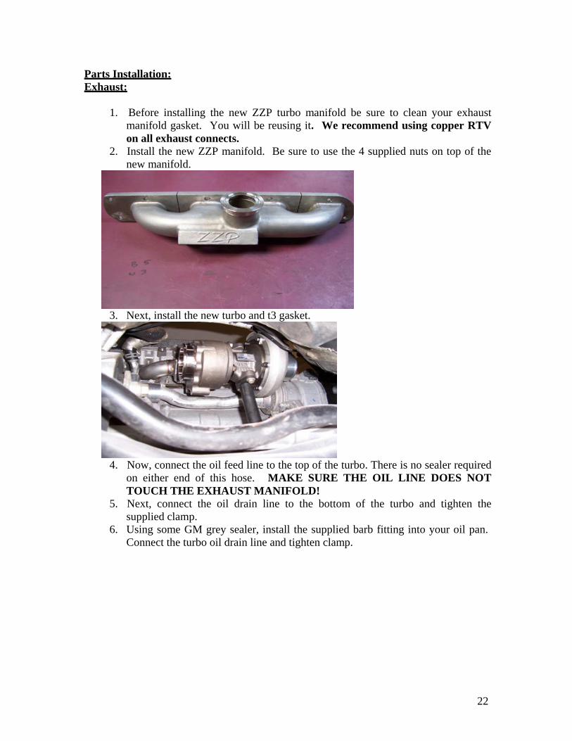
Parts Installation: Exhaust:
1. Before installing the new ZZP turbo manifold be sure to clean your exhaust manifold gasket. You will be reusing it. We recommend using copper RTV on all exhaust connects.
2. Install the new ZZP manifold. Be sure to use the 4 supplied nuts on top of the new manifold.
3. Next, install the new turbo and t3 gasket.
4. Now, connect the oil feed line to the top of the turbo. There is no sealer required on either end of this hose. MAKE SURE THE OIL LINE DOES NOT TOUCH THE EXHAUST MANIFOLD!
5. Next, connect the oil drain line to the bottom of the turbo and tighten the supplied clamp.
6. Using some GM grey sealer, install the supplied barb fitting into your oil pan. Connect the turbo oil drain line and tighten clamp.
22

7. Before installing the new turbo dp, install any O2 sensors. Install the new turbo
down pipe on the turbo using the supplied V-band clamp. Do not tighten. 8. Next, connect the down pipe to the cat-back. Once you finished the connection
at the cat back tighten the V-band on the turbo and then tighten the rear section of the down pipe.
9. Now, install the new wastegate and dump tube.
10. Next, install the 3”to 3.5” 90 degree coupler on the turbo.
11. Install the new turbo intake, filter and clamp. The intake does not hit the firewall; if it does you need to make some adjustments to either the intake or the coupler on the turbo.
23

Intake and fuel system: 1. BE SURE TO CLEAN ALL SURFACES PRIOR TO INSTALLATION OF
THE INTAKE MANIFOLD, INJECTOR O-RINGS AND INJECTOR CUP O-RINGS. ALL INJECTOR O-RINGS AND INJECTOR CUP O-RINGS NEED TO BE INSPECTED FOR TEARS OR CRACKS BEFORE INSTALLING THEM. ALSO, ALL O-RINGS NEED TO BE GREASED BEFORE INSTALLATION.
2. Install your factory map sensor into the bottom of your new intake.
3. Locate the factory map sensor plug. You need to pull about 3-4” of wire out of the factory loom. This will allow the map sensor plug to reach its new location.
4. Next, install the new intake manifold gasket and manifold using the supplied bolts and torque to 16lb/ft.
5. Next, install your injector cups into the cylinder head and new injectors into the
fuel rail. Then, plug in your new injector harness that is supplied in the kit. Install your fuel rail, connect the fuel feed line and tighten the rail.
6. Now, install your coolant overflow line. 7. Using some GM grey sealer, install your new throttle body. You can also plug in
your throttle body adaptor harness. 8. You can now move on to installing the new alternator using the supplied
hardware. 9. Once you have finished the alternator install you can install the supplied belt.
24

10. Install supplied radiator hose.
11. At this point you can plug in the map sensor, coolant temp, alt., barometric pressure sensor, throttle body and injectors. Your blower inlet pressure sensor can remain unplugged; you will not be using it.
12. The fitting on your intake that is labeled evap can also be plugged in at the intake manifold and at the evap solenoid with the provided hose.
25

13. Now, install the supplied fitting on the intake manifold labeled brakes. Connect the barbed end of the new fitting to your brake booster line. You must remove the original fitting.
14. Install the new dipstick that is supplied in the kit. Be sure to grease the o-ring.
Intercooler and Intercooler Piping: 1. Before installing the ZZP intercooler you must trim some of the bumper
reinforcement. 2. After trimming, you can install the ZZP intercooler using the supplied hardware.
When installing the ZZP intercooler you may have to bend the A/C lines slightly to make room for the new piping.
3. Evenly align the IC side to side by referencing the bracket in the bumper reinforcement. Make sure to adjust all heights before tightening any screws.
26

4. Next, install the passenger side 2.5” to 2.5” 90* coupler on the intercooler with a
slight upward rotation where it passes over the cradle. The longer leg of the coupler goes on the intercooler. Necessary clamps: 2 clamps (288)
5. Now, install the driver side double 90* coupler. The longer leg of the coupler goes on the intercooler. Necessary clamps: 2 clamps (288)
27

6. Next, install the 2” to 2.5” 90* coupler on the turbo with the 2.5” opening facing
the driver fender. 2 clamps (250&288)
7. Install the 2.5” to 2.75” 90* coupler on the throttle body with the 2.5” opening
facing the driver fender. 2 clamps (288&325) 8. If you have not removed the blower bypass solenoid you will need to at this time
to make room for the new upper charge pipe. You will not be using the bypass.
9. Install the upper charge pipe on the stud that mounts the evap solenoid. Mount the evap solenoid on the same stud after the intercooler pipe mounting tab is in place or on the bolt below.
10. Now that the pipe is installed check for proper alignment and tighten all clamps 11. Next, install the maf sensor in the lower intercooler pipe.
28

12. Now, install the lower charge pipe. Be sure to attach the lower charge pipe bracket on the oil cooler stud using the supplied nut. Plug in the maf sensor.
13. Install the blow off valve on your upper charge pipe and connect the vacuum line from the manifold labeled BOV. You must use the o-ring that comes with the bov! Make sure to use the supplied zip ties on all vacuum line connections!
Boost Control: READ THIS!
Boost control is one of the most important parts of a turbo setup. It can literally make or break an engine so it is important to understand how it works. We label your hoses to help prevent any issues but some still arise. If you have read through this there should be no reason to call and ask us questions about setting up the boost control. If you don’t understand, read through the instructions until you do. Your boost controller will be setup when you receive your kit. This information is for your own benefit.
The wastegate on your exhaust manifold is responsible for controlling exhaust flow to your turbochargers turbine wheel. The valve opens and diverts excess exhaust gas away from the turbine wheel to help maintain the speed of the turbine. The simplest closed- loop control for a wastegate is to supply boost pressure directly from the charge air side to the bottom port on an external wastegate. A small hose can connect from the intake manifold to the nipple on the bottom of the external wastegate. The wastegate will open further as the boost pressure pushes against the force of the spring in the wastegate until equilibrium is obtained.
A dual port wastegate (which is what you are using) allows pressure to be added to the top of the wastegate. Air pressure allowed to enter this second port aids the spring to push harder in the direction of closing the wastegate. This is exactly the opposite of the first port. If you hook pressure only to the bottom of the wastegate it will open at what ever pressure the spring is inside the gate. In your case it’s a 0.6bar or 8.7psi spring. If you hook up pressure only to the top of the wastegate it will never open and you will blow your motor up!
29

The way we are controlling the wastegate on your vehicle is a regulator style boost control. You send intake manifold pressure to the bottom port on your wastegate via the labeled vacuum line. Next, you send intake manifold pressure to the non-arrow side of the regulator. Then, coming out of the regulator on the side with the arrow, you run your vacuum line to the top of your wastegate. The pressure going into the regulator is higher than the pressure coming out (regulated pressure), which aids in adding to the wastegate spring. Wastegate base spring pressure= 9psi + 1psi regulated pressure= 10psi. If you added 4psi of regulated pressure you would be at approximately 13psi. To adjust the regulated pressures simply turn the knob clockwise to raise pressure and counterclockwise to lower the pressure. Each 360 degree turn is approximately 3psi of regulated pressure. When you receive your kit, the regulator will be set at its lowest setting. The first full turn will make little to know change in boost.
Finishing:
1. Install your supplied spark plugs with a gap of .032. 2. Install bumper cover, plastic, and head lights. 3. Install your new pcm. 4. Fill oil and coolant. 5. Connect the battery. 6. Make sure to check all connections, fittings, clamps, bolts, zip ties or any other
installed parts to verify that they have all been securely fastened. 7. Start your car and enjoy. 8. THANK YOU FOR YOUR BUSINESS!
30

Finished Product!
31