lsb directives on engineering & hydrographic survey … · lsb directives on engineering &...
TRANSCRIPT

LSB Directives on Engineering & Hydrographic Survey Practices
LSB DIRECTIVES
ON ENGINEERING
& HYDROGRAPHIC
SURVEY PRACTICES
The Directives are available on the Land Surveyors Board Singapore website at URL: http://www.minlaw.gov.sg/lsb LAND SURVEYORS BOARD SINGAPORE c/o SINGAPORE LAND AUTHORITY 55 Newton Road #12-01 Revenue House Singapore 307987 SEPTEMBER 2013 Version 4.0

LSB Directives on Engineering & Hydrographic Survey Practices
Revision History
Revision
Version 1.0 March 2004
Version 2.0 March 2005 : Consequent to adoption of SVY21 Datum and also changes to the Land Surveyors Act
Version 3.0 April 2007: Incorporated a new section 8 on Gazette Notification, GPS RTK & Deformation Surveys
Version 4.0
21 March, 2013 : Incorporated a new section 8 – Multibeam Echo Sounding Survey and updated Section 1.1.3 on the requirements of Authorised Field Assistant/Qualified Hydrographic Assistant

LSB Directives on Engineering & Hydrographic Survey Practices
TABLE OF CONTENTS
1. INTRODUCTION .................................................................................................................. 1
1.1 Registration of Surveyors and Authorised Assistant ................................................... 1
1.1.1 Registration of Surveyors ..................................................................................... 1
1.1.2 Licensing of Corporations .................................................................................... 1
1.1.3 Employment of Authorised Assistant (Engineering and Hydrographic Surveys) 2
2. DIRECTIVE ON SURVEY PRACTICES ................................................................................. 2
2.1 Control and Datum ...................................................................................................... 2
2.2 Instrumentation and Accuracy .................................................................................... 2
2.3 Compliance with Contract Specifications ................................................................... 3
2.4 Method of Survey ........................................................................................................ 3
2.5 Field Survey Record ..................................................................................................... 3
2.6 Survey Computation .................................................................................................... 4
2.7 Preparation of Survey Plan .......................................................................................... 4
2.8 Submission of Plans and Survey Records .................................................................... 6
3. DIRECTIVE ON CONTROL SURVEY ....................................................................................... 6
3.1 Horizontal Control ....................................................................................................... 6
3.2 Vertical Control ........................................................................................................... 6
3.3 Minimum Closure Standards for Control Survey ........................................................ 6
3.4 Permitted Deviation for Control Survey ...................................................................... 7
4. DIRECTIVE ON SETTING-OUT SURVEY ................................................................................ 7
4.1 Measurement .............................................................................................................. 7
4.2 Survey Marker ............................................................................................................. 8
4.3 Permitted Deviations for Setting Out Survey .............................................................. 8
5. DIRECTIVE ON AS-BUILT/TOPOGRAPHICAL SURVEY .......................................................... 9
5.1 SVY21 Datum ............................................................................................................... 9
5.2 Spot Levels ................................................................................................................... 9
5.3 Level of details to be surveyed .................................................................................... 9
6. DIRECTIVE ON SPECIFICATIONS FOR A/E/C AND FACILITY MANAGEMENT ..................... 10
7. DIRECTIVE ON HYDROGRAPHIC SURVEY .......................................................................... 10
7.1 Land Surveyors (Exemption) (No 2) Order 2004 ....................................................... 10
7.2 Hydrographic Survey ................................................................................................. 11
7.3 Method of Survey ...................................................................................................... 11
8. MULTIBEAM ECHO SOUNDING SURVEY FOR ENGINEERING PROJECTS ........................... 12
8.1 Survey Accuracy ........................................................................................................ 12
8.2 Calibration ................................................................................................................. 13
8.3 Coverage and Detection of Seabed Features ............................................................ 13
8.4 Tidal Reduction .......................................................................................................... 13
8.5 Logging of Digital Depths .......................................................................................... 13

LSB Directives on Engineering & Hydrographic Survey Practices
8.6 Acquisition and Processing........................................................................................ 14
8.7 Other Corrections during Processing ........................................................................ 14
8.8 Field Surveys Records ................................................................................................ 14
8.9 Survey Grid ................................................................................................................ 15
8.10 Tidal Corrections ....................................................................................................... 15
8.11 Survey Plans .............................................................................................................. 15
8.12 Depth Contours ......................................................................................................... 15
8.13 Submission of Plans and Survey Records .................................................................. 15
9. DIRECTIVES ON GAZETTE NOTIFICATION, GPS RTK AND DEFORMATION SURVEYS ........ 16
9.1 Gazette Notification Surveys ................................................................................. 16
9.2 Deformation Survey and Analysis .......................................................................... 16
9.3 Directive on GPS RTK Survey ..................................................................................... 18
(a) Personnel ...................................................................................................................... 18
(d) RTK Initialization ........................................................................................................... 19
(f) Vertical datum .................................................................................................................. 20
REFERENCES ............................................................................................................................. 21
1. DEFORMATION SURVEY BASICS ....................................................................................... 28
2. LIFE CYCLE PROJECT MANAGEMENT ................................................................................ 28
3. DEFORMATION PARAMETERS .......................................................................................... 29
4. LOCATION OF MONITORING POINTS ............................................................................... 29
5. DESIGN OF REFERENCE NETWORKS ................................................................................. 30
6. DESIGN OF MEASUREMENT SCHEMES ............................................................................. 31
7. MEASUREMENT RELIABILITY ............................................................................................ 33
8. FREQUENCY OF MEASUREMENTS .................................................................................... 35
9. DEFORMATION MEASUREMENT ...................................................................................... 36
10. GEOMETRICAL DEFORMATION ANALYSIS .................................................................... 45

LSB Directives on Engineering & Hydrographic Survey Practices 1
1. INTRODUCTION
These Directives cover Engineering Survey, Hydrographic Survey, and surveys on setting out and as-built survey. No attempt is made to detail how such surveys should be carried out. The directives cover the standard and essential specifications of survey practices demanded of a Registered Surveyor. Registered Surveyors have to determine the appropriate equipment and methodology to satisfy their client’s specifications. The directives are not intended to substitute technical specifications stipulated by the clients of Registered Surveyors when the specifications are of higher or lower demand. Contractual agreements on specifications entered into between the Registered Surveyor and his client shall take precedence over these directives in the event of disputes. Such contractual agreements shall also preside where the directives do not cover the types of survey being undertaken. Contractual engagement of Registered Surveyors shall not contravene the Land Surveyors Act. The directives are by no means exhaustive. As new technologies and methods evolve, the directives will be adapted to embrace and to leverage on these developments as well as to respond to changing business needs.
1.1 Registration of Surveyors and Authorised Assistant
1.1.1 Registration of Surveyors
A Surveyor shall only practise if:
(a) His name is in the Register of Surveyors; and
(b) His name is in the Annual Register of Practitioners.
(i) Application for registration A person who meets the requirements for registration as a surveyor can apply to the Land Surveyors Board on a prescribed form accompanied by the requisite documents and a cheque for the prescribed fee made payable to Land Surveyors Board Singapore. For more information, visit the Board website at http://www.minlaw.gov.sg/lsb.
(ii) Application for practising certificates
A Registered Surveyor who wishes to practise Cadastral, Engineering and Hydrographic Surveys in Singapore is required to apply to the Board for a Practising Certificate on a prescribed form accompanied by the requisite documents and a cheque for the prescribed fee made payable to Land Surveyors Board Singapore. For more information, visit the Board website at http://www.minlaw.gov.sg/lsb.
1.1.2 Licensing of Corporations
A corporation or partnership which intends to provide Engineering and Hydrographic survey services is required to have a licence granted by the Land Surveyors Board.

LSB Directives on Engineering & Hydrographic Survey Practices 2
Application for a licence should be made on a prescribed form accompanied by the requisite documents and a cheque for the prescribed fee made payable to Land Surveyors Board Singapore. For more information, visit the Board website at http://www.minlaw.gov.sg/lsb.
1.1.3 Employment of Authorised Assistant (Engineering and Hydrographic Surveys)
A Registered Surveyor shall employ field assistants who are TechSISV or equivalent qualifications acceptable to SISV to carry out engineering work. Engineering Surveys
For the conduct of Engineering Surveys the qualified assistant shall be an Authorised Assistant approved by the Chief Surveyor, Singapore Land Authority. For more information, refer to CS Directives on Cadastral Survey Practice. Hydrographic Surveys
For the conduct of Hydrographic Surveys the qualified assistant shall be an Authorised Assistant approved by the Chief Surveyor, Singapore Land Authority or a qualified assistant who has conducted hydrographic surveys in Singapore waters over a period of at least 3 years under the direct supervision of an FIG/IHO Category ‘A’ Hydrographic Surveyor. The Category ‘A’ Hydrographic Surveyor will have to certify that the qualified assistant is competent to conduct a hydrographic survey and has worked under his supervision for a period of not less than 3 years in Singapore waters.
2. DIRECTIVE ON SURVEY PRACTICES
2.1 Control and Datum
(a) Co-ordinated control points are established at the initial stages of a project,
normally in the preparation of a topographic or engineering survey. These control points should be viewed as control for setting out and are to be observed and adjusted to the required accuracy. The observation scheme should form a self-checking network which is linked to the Singapore Land Authority (SLA) Integrated Survey Network (ISN) as defined in the CS Directive on Cadastral Survey Practices;
(b) Height control is extremely important in any construction project and the most
accurate results are still only attainable with traditional levelling techniques, using either digital or optical level. The control should form a self-checking network, which is linked to the SLA Precise Levelling Datum (PLD). All levels should be based on PLD. One hundred metres (100 m) may be added to the reduced levels of PLD for engineering survey and an explanatory note is to be included in the plan.
(c) The Chart Datum established by the MPA Hydrographic Department shall be
adopted as the datum for sounding. Reference shall be made to MPA Tide Table.
2.2 Instrumentation and Accuracy
1

LSB Directives on Engineering & Hydrographic Survey Practices 3
It is particularly important that Registered Surveyors involved in setting out have an understanding of instrumental accuracies and the theory of errors. Appendix A provides a guideline on accuracy of survey instrument.
The following calibration procedures are the minimum requirements before executing
a surveying task:- (a) Electronic Distance Meter or Electronic Total Station used in the survey shall be
properly calibrated at the Lower Pierce EDM Calibration Base set at atmospheric condition of 28 deg C and 760 mm Hg in accordance with CS Directive on Cadastral Survey Practices;
(b) Levelling instrument shall be calibrated by 2-peg method before they are used
each day and after service. The Registered Surveyor shall maintain the calibration records.
(c) Equipment for hydrographic survey shall be properly calibrated before they are
used. Registered Surveyor shall maintain the calibration records. (d) The accuracy of the survey equipment used must be compatible with the
stipulated accuracy of the survey.
2.3 Compliance with Contract Specifications
Clients have the prerogative to stipulate specifications other than those specified in
these directives. In these circumstances, the contract specifications of more stringent demand shall prevail over the specifications stipulated in these directives.
2.4 Method of Survey
Where no survey specifications are stipulated by a client, the Registered Surveyor shall adopt or devise a method of survey that produces results complying with the required accuracy stipulated in these directives.
2.5 Field Survey Record
(a) Registered surveyor shall maintain proper field records for inspection whenever
required; (b) All entries in survey record are to be made in ink. Inking over pencilled entries
and transcribing from other records are expressly forbidden; (c) Every incorrect entry shall be cancelled by one horizontal stroke through all
figures which shall remain legible after the cancellation; (d) The corrected entry shall be written in full above the cancelled entry; no figure
shall be altered, erased or obliterated; (e) Electronic data logger may be used in the survey. Registered Surveyor shall
ensure that all electronic data are properly documented and archived.

LSB Directives on Engineering & Hydrographic Survey Practices 4
2.6 Survey Computation
(a) Least squares adjustment shall be used to adjust traverse and levelling
network; (b) Areas of lots and plots shall be computed using any method to the nearest
tenth of a square metre (0.1 sq.m.); (c) Scaled areas shall be entered to the nearest square metre and distinguished by
the abbreviation “Sc.” after the areas. (d) For provisional areas and boundaries, a note “Areas, boundaries and
dimensions shown hereon are provisional and subject to alteration on final survey.” shall be entered on all the survey plans, sketches and computation sheets;
(e) Pre-computation for setting-out purpose shall follow the design layout plans or
other approved drawings; (f) Salient locations shall be co-ordinated and pre-computed dimensions of
clearance shall be reflected on pre-computation plans.
2.7 Preparation of Survey Plan
The following information shall be included in the preparation of the various survey
plans: (a) As-Built/Topographic/ Planimetric Plan
(i) Boundary marks which demarcate the property boundaries and ISN markers and their reference number;
(ii) Lot boundary and numbers;
(iii) Size and position of existing features such as trees, ponds, roads, footpaths and structures;
(iv) Public service structure like gas and telecom manholes, lamp posts, hydrants, water keyboxes, electric boxes and sewerage manholes;
(v) Existing watercourse (with direction of flow indicated) including earthstreams, drains, bridges and culverts and invert levels;
(vi) Spot levels and level datum adopted;
(vii) Any other salient features exposed at site and falling within the survey corridor;
(viii) Grid lines;
(ix) Title boxes as shown in Sample Drawing A. (b) Setting Out Plan
(i) Boundary stones, nails, spikes, cut-marks etc which demarcate the property boundaries and their reference number;

LSB Directives on Engineering & Hydrographic Survey Practices 5
(ii) Lot boundary and lot numbers;
(iii) Field traverse and control stations with co-ordinates shall be indicated;
(iv) Intersecting point, at centreline of proposed route, and their coordinates;
(v) Benchmarks and their reduced levels;
(vi) Pegs or reference points established on site;
(vii) Grid lines.
(viii) Title boxes as shown in Sample Drawing B. (c) Longitudinal Section Plan
(i) Invert levels of the existing drain/earth stream;
(ii) Ground levels of the centre line of proposed route;
(iii) Levels of both existing copes of drains;
(iv) Soffit levels and widths of bridges and culverts;
(v) Invert levels at inlet and outlet of bridges and culverts including their lengths;
(vi) Road levels above culverts and outlets of connecting drain;
(vii) Levels of both existing earth banks;
(viii) Service crossing drains and their invert levels. (d) Cross-Section Plan
(i) Cross section shall be taken at every 30 m interval unless otherwise specified;
(ii) Additional cross sections shall be produced at every road culvert, bridge and existing structure within the survey corridor;
(iii) Cross sections shall be taken at right angle to the centre-lines where they are straight and radially where they are curvilinear;
(iv) Cross sections shall indicate the dimensions and levels of existing earth streams, drains, culverts, crossing tracks, posts, tree, ponds or any other features or structures within the survey corridor to show the existing surface profile.
(e) Bathymetric Plan
(i) Digital depths in metres & decimetres at Chart Datum.
(ii) Land features if adjacent to area of survey.
(iii) Tidal station used.
(iv) Datum details.

LSB Directives on Engineering & Hydrographic Survey Practices 6
(v) Scale.
(vi) Date of survey.
(vii) Grid lines.
(viii) Title boxes as shown in Sample Drawing C.
2.8 Submission of Plans and Survey Records
All plans, field records, reports, data sheet, equipment calibration records, etc shall
be certified by the Registered Surveyor.
3. DIRECTIVE ON CONTROL SURVEY
3.1 Horizontal Control
The horizontal control for every survey shall consist of at least four (4) ISN markers.
Boundary markers should not be used to determine the datum. The ISN markers shall as far as possible, encompass the site under survey, and
could be used only if the residuals in Northing and Easting co-ordinates are within 0.020 m of the recorded ISN values for GPS surveys.
3.2 Vertical Control
(a) A localised network of stable benchmarks shall be established in conjunction
with every survey requiring vertical heights. However, vertical control used for monitoring structure movement shall be surveyed and adjusted as an independent network.
(b) The vertical datum shall be derived from at least two (2) reliable Vertical Control
Points (VCP), each verified with two (2) witness marks established by SLA; (c) All primary levelling shall be executed by standard precise levelling procedure.
(d) Where a local vertical control is to be established for allowable height accuracy
of 5 cm, the geometric geoid model established by SLA might be adopted to convert ellipsoidal heights, obtained in accordance to the recommended procedure published by SLA, to reduced levels.
3.3 Minimum Closure Standards for Control Survey
Accuracy standards of control survey is normally specified, classified, and reported
based on the horizontal (linear) point closure ratios or the vertical elevation difference closures.
Second- and Third-Order standards (1:20,000 and 1:10,000 respectively) are
adopted in most engineering and construction projects. Only projects requiring exceptionally high accuracy warrant the use of First-Order survey with 1:50,000 or even 1:100,000 relative accuracy.

LSB Directives on Engineering & Hydrographic Survey Practices 7
The minimum closure standards for horizontal and vertical surveys in the field work are shown in Tables 1 and 2. Most construction works are performed to Third-Order standards.
Table 1 Minimum Closure Standards for Horizontal Control Surveys
Table 2 Minimum Closure Standards for Vertical Control Surveys
Classification Order Closure Standard Elevation Closure Standard Classification Order (mm)
Engr & Const Distance Angle Control (Ratio) (Secs)
First-Order 1:50,000 3√N
(1)
Second-Order 1:20,000 5√N
Third-Order 1:10,000 10√N
First-Order 1.5 √K
(2)
Second-Order 6√K
Third-Order 12√K
(1)
√N = Number of angle stations (2)
√K = square root of distance in kilometres
3.4 Permitted Deviation for Control Survey
The closure standard is not a robust indicator of precision. Permitted Deviation (PD)
for First- and Second-Order control survey, as shown in Table 3, shall be used to compare measured distances and bearings with those derived from the known or adjusted co-ordinates. The permitted deviation for Third-Order control is task-dependent and thus is identical to the permitted deviation for setting out as shown in Table 4.
Table 3 Permitted Deviations for Horizontal & Vertical Control Surveys
Permitted Deviation
First Order Second Order
Distance (mm) ± ( 0.5 √L) ± ( 1.5 √L)
Bearing (deg) ± (0.025 ÷ √L) ± (0.09 ÷ √L)
Vertical (mm) ± ( 12 √K) ± 3
where L is the distance, in metres, between the points concerned and K is the distance levelled in kilometre.
4. DIRECTIVE ON SETTING-OUT SURVEY
4.1 Measurement
(a) Angle and bearing measurements shall be observed, checked and recorded to
the specified accuracy of the instrument; (b) All traverse distances, recorded to 0.001 m, shall be made in both the forward
and reverse direction. (c) An independent observation from another station shall be included for checks
on accuracy. (d) Non-invar levelling staves are to be read and booked to 0.001 m; (e) Digital levels should be configured so as to allow repeat observations, with the
standard deviation after five observations to be maintained at 0.001m or less;

LSB Directives on Engineering & Hydrographic Survey Practices 8
(f) For GPS setting out, a repeat observation at the set-out point is to be taken later after a minimum of 30 minutes.
4.2 Survey Marker
(a) Appropriate survey markers of durable nature shall be provided on concrete
surface or natural ground for control purposes; (b) Wooden pegs of suitable length and cross-section shall be used to mark setting
out points; (c) Reference pegs shall be established for the baseline and all intersection points; (d) Survey stakes, batter boards and other devices shall be of such configuration
and dimensions as to completely fulfil their function with respect to precision requirements and period of use
4.3 Permitted Deviations for Setting Out Survey
The principle of accuracy acceptance criteria for control points and setting out points
has been established in BS 5964 “Building setting out and measurement” which is accepted internationally. The criteria specified are in terms of relative rather than absolute accuracies and are given as Permitted Deviation (PD) for distances, bearings, angles and levels, as shown in Tables 4 & 5.
(a) Horizontal and Vertical Setting Out There are many setting out tasks in construction activities and it is not possible
to classify them all. Broadly, setting out surveys are classified into four categories:-
(i) Category 1 – structure (ii) Category 2 – roadworks (iii) Category 3 – drainage works (iv) Category 4 – earthworks The acceptance criteria quoted relate to distances, angles and levels and apply
whether they are measured from a higher-order point or between two points in the same category. The differences between the calculated and observed distances, angles and levels should not exceed the following PDs:
Table 4 : Permitted Deviations for Horizontal and Vertical Setting Out Survey
Permitted Deviation (PD)
Structure Roadworks Drainage Earthworks
Distance (mm) ± ( 1.5 √L1) ± ( 5.0 √L1) ± ( 7.5 √L1) ± ( 10.0 √L1)
Angle (degree) ± (0.09 ÷ √L2) ± (0.15 ÷ √L2) ± (0.20 ÷ √L2) ± (0.30 ÷ √L2)
Height Difference (mm) ± 3 ± 5 ± 20 ± 30
where L1 is the distance, in metres, between the points concerned and L2 is the shorter of the two distances defining the angle.
LSB Directives on Engineering & Hydrographic Survey Practices 9
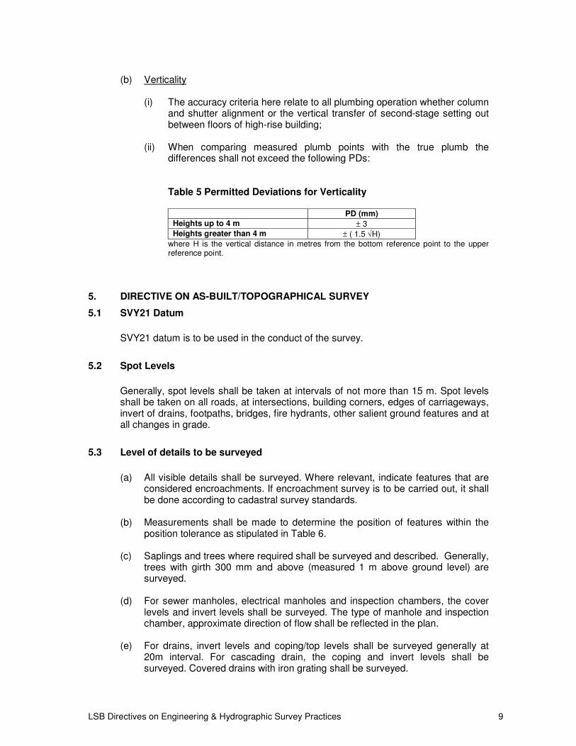
(b) Verticality (i) The accuracy criteria here relate to all plumbing operation whether column
and shutter alignment or the vertical transfer of second-stage setting out between floors of high-rise building;
(ii) When comparing measured plumb points with the true plumb the
differences shall not exceed the following PDs: Table 5 Permitted Deviations for Verticality
PD (mm)
Heights up to 4 m ± 3
Heights greater than 4 m ± ( 1.5 √H)
where H is the vertical distance in metres from the bottom reference point to the upper reference point.
5. DIRECTIVE ON AS-BUILT/TOPOGRAPHICAL SURVEY
5.1 SVY21 Datum
SVY21 datum is to be used in the conduct of the survey.
5.2 Spot Levels
Generally, spot levels shall be taken at intervals of not more than 15 m. Spot levels
shall be taken on all roads, at intersections, building corners, edges of carriageways, invert of drains, footpaths, bridges, fire hydrants, other salient ground features and at all changes in grade.
5.3 Level of details to be surveyed
(a) All visible details shall be surveyed. Where relevant, indicate features that are
considered encroachments. If encroachment survey is to be carried out, it shall be done according to cadastral survey standards.
(b) Measurements shall be made to determine the position of features within the
position tolerance as stipulated in Table 6. (c) Saplings and trees where required shall be surveyed and described. Generally,
trees with girth 300 mm and above (measured 1 m above ground level) are surveyed.
(d) For sewer manholes, electrical manholes and inspection chambers, the cover
levels and invert levels shall be surveyed. The type of manhole and inspection chamber, approximate direction of flow shall be reflected in the plan.
(e) For drains, invert levels and coping/top levels shall be surveyed generally at
20m interval. For cascading drain, the coping and invert levels shall be surveyed. Covered drains with iron grating shall be surveyed.

LSB Directives on Engineering & Hydrographic Survey Practices 10
(f) Over-ground electric boxes, lamp/cable posts with numbers, exposed/overhead cables, etc shall be surveyed.
(g) Cross-sections must be right-angle to centre line and shall be surveyed
generally at 30m interval and 15m along curves, tunnels roads etc. (h) Road names and house/block numbers shall be picked up and shown. (i) Edges of pond shall be surveyed.
6. DIRECTIVE ON SPECIFICATIONS FOR A/E/C AND FACILITY MANAGEMENT
SVY21 datum is to be used in the conduct of the survey. The following specifications are extracted from PART 4 of the Geospatial Positioning
Accuracy Standards proposed by U.S. Federal Geographic Data Committee entitled “Standards for A/E/C and Facility management, 1 July 1998 (Public Review Draft)”. Modifications to some of the adopted scales had been made to bring them in line with metric convention.
This PART 4 provides accuracy standards for engineering drawings, maps, and
surveys used to support planning, design, construction, operation, maintenance, and management of facilities, installations, structures, transportation systems, and related projects. It is intended to support geospatial mapping data used in various engineering documents, such as architectural, engineering, and construction (A/E/C) drawings, site plans, regional master planning maps, and related Geographical Information System (GIS), Computer-Aided Drafting and Design (CADD), and Automated Mapping/Facility Management (AM/FM) products. These products are typically created from terrestrial, satellite, acoustic, or aerial mapping techniques that output planimetric, topographic, hydrographic, or feature attribute data.
The standard was largely taken from existing U.S. Army Corps of Engineers
engineering surveying, and mapping standards, and from the Department of Defense Tri-Service Facility Engineering CADD/GIS standards and the American Society for Photogrammetry and Remote Sensing (ASPRS) “Accuracy Standards for Large-Scale Maps”.
General guidance for determining project-specific mapping accuracy standards is
contained in Appendix B. This table may be used in developing specifications for map scales, feature location and elevation tolerances, and contour intervals for typical A/E/C project.
7. DIRECTIVE ON HYDROGRAPHIC SURVEY
7.1 Land Surveyors (Exemption) (No 2) Order 2004
The Land Surveyors (Exemption) (No 2) Order 2004 was published vide GN No.
S79/2004 in the Government e-Gazette on 26 February 2004. The Exemption Order states:

LSB Directives on Engineering & Hydrographic Survey Practices 11
“Section 10 of the Act shall not apply to any person who carries out or causes to be carried out any hydrographic or hydrologic survey or other study of the waters and sea-bed within the territorial limits of Singapore for navigational purposes or studies of marine science and ecology.”
7.2 Hydrographic Survey
Pursuant to the Exemption Order, hydrographic or hydrologic survey or other study of
the waters and sea-bed as stated in the Order shall not be within the purview of the Land Surveyors Act (Chapter 156). Such survey can only be carried out with the approval of the Maritime and Port Authority of Singapore under the MPA Act (Chapter 170A).
A Registered Surveyor under the Land Surveyors Act is permitted to carry out the
following hydrographic surveys and studies that are not relating to maritime navigation:
(a) Foreshore Construction in respect of land reclamation, shore protection works,
bunds, retaining walls and outfall/intake structures; (b) Residential and commercial properties/facilities/structures located along the
foreshore; and (c) Soil Investigation
7.3 Method of Survey
(a) Positioning Horizontal positioning is to be controlled by Differential Global Positioning
System with an accuracy ±1m or better. The DGPS shall be checked against a known coordinated position before and after survey each day.
(b) Echo Sounder Depths shall be recorded with Dual Frequency Echo Sounder (about 30 kHz
and 210 kHz). The echo sounder shall be calibrated by bar checks up to the maximum depth expected in the survey area before and after sounding each day. The records of such Bar Checks shall be marked on the same echo roll used for the particular day’s sounding.
(c) Sounding Line Interval and Sounding Density Sounding lines shall be spaced at interval of 5m and at closer interval where
seabed is irregular and high spots are detected. Sounding shall be recorded at 3m or less along each sounding line. Cross lines shall be run at 10 times the line interval of the sounding lines.
(d) Sounding Datum Vertical Datum shall be the datum used for soundings unless otherwise
specified in the survey requirements. The Vertical Datum used shall be clearly stated on all survey plans. The relationship between Vertical Datum and Precise Levelling Datum shall also be shown.

LSB Directives on Engineering & Hydrographic Survey Practices 12
(e) Tidal Corrections Tidal Recordings for reduction of soundings may be taken from nearest
automatic tide gauge station if the tidal character in range and time are similar or from a tide gauge established by the surveyor and Vertical Datum on the gauge related to official Benchmarks or VCPs.
(f) Interpretation of Soundings High Spots detected on the analogue trace unless conclusively proven to be
false echo shall be plotted on the survey plan. (g) Survey Grid The survey results shall be plotted on the SVY21 grid in metres based on the
Transverse Mercator Projection with false origin coordinates 38744.572N 28001.642E at Latitude 1° 22' 00" N Longitude 103° 50' 00" on WGS84 Spheroid, and Central Meridian scale factor of 1. (ISN)
(h) Field Survey Records The following records shall be presented:
(i) All depths and position data shall be recorded digitally in real time. The raw data comprising date, time, x, y, z shall be presented in ASCII
format.
(ii) On all echo traces the name of surveyor, bar check, date & time, fix numbers shall be annotated.
(iii) Record of field equipment calibration.
(iv) The actual track plots of the survey vessel.
(v) Tidal Records.
8. MULTIBEAM ECHO SOUNDING SURVEY FOR ENGINEERING PROJECTS
Where Multibeam Echo Sounding Survey (MBES) is required the Registered Surveyor shall comply with these directives unless contractual specifications are given.
8.1 Survey Accuracy
In general the standards of MBES shall be as follows:
(a) Seafloor coverage 100% with 1m grid cells (b) Feature Detection 1m³ (c) Positioning Accuracy ±1m (d) Maximum Allowable Total Vertical Uncertainty 95% Confidence Level ± √[a²+(b x depth)² ] where a = 0.25m b = 0.0075m depth in metres

LSB Directives on Engineering & Hydrographic Survey Practices 13
(e) Frequency – 200kHz to 400kHz The MBES complete with Gyro/Motion Sensors and Sound Velocity Profiler, DGPS and Tide Gauges selected shall conform to the above standards.
8.2 Calibration
The relative positions and heights of the Multibeam Echo Sounder’s Transducer, Gyro Compass, Heave, Roll & Pitch Sensors and GPS Antenna are to be measured and the offsets from the survey vessel’s axes are to be integrated in the software. In addition the draft of the vessel fore and aft shall be measured for vessel with LOA 25m or larger. The vessel’s squat and settlement at different survey speed shall be determined. Field calibration shall be based on the principle of repeatability in that the seafloor or objects ensonified shall appear the same in whatever the azimuth, at whatever the speed and whatever the motion history of the survey vessel. These field calibrations known as the patch tests shall be conducted prior to the commencement of the survey and at any significant component changed and daily. Sound Velocity profile shall be conducted prior to the patch tests.
8.3 Coverage and Detection of Seabed Features
The swath to swath overlap shall attained 100% seafloor coverage. The full swath shall be logged. However, only the section of the swath that complied with the accuracy standards shall be utilised. The sounding tracks shall be maintained parallel and preferably parallel to the bathymetric contours. The ping rate of the MBES shall be set such that at the survey speed of the vessel the seabed is ensonified at least at every 0.5m interval along the track. The MBES shall be capable of detecting seabed features of 1m cube. The patch tests shall be conducted to resolve the following biases:
• Latency - DGPS and Multibeam Echo Sounder using GPS 1PPS
• Roll Offset - Swath Sounder
• Pitch Offset - Swath Sounder
• Yaw Offset - Swath Sounder When all calibrations are done the various offsets can be calculated. There is a need for accurate alignment of the sensors’ offsets and a number of iterations have to be conducted to cancel out the influences of the different parameters.
8.4 Tidal Reduction
All depths recorded shall be reduced to Chart Datum from tide recordings of the nearest MPA Tide Gauge Station.
8.5 Logging of Digital Depths

LSB Directives on Engineering & Hydrographic Survey Practices 14
The software used shall be capable of logging the full swath return pings and coordinates both derived from DGPS and dead reckoning between DGPS measurements. The latency of the DGPS and the echo pings shall be set and applied from the 1PPS signal in real time. The biases of latency, roll, pitch and yaw from the patch tests shall be corrected by the acquisition software prior to logging the data.
8.6 Acquisition and Processing
The number of spikes shall be minimised in the Multibeam Echo Sounder acquired data by setting parameters affecting power, gain and filter of the received data. Generally the following parameters need to be set:
• Power Level
• Transmit Pulse
• Fixed Gain and Time Varied Gain
• Speed of Sound
• Range
• Ping Rate
• Depth Filter
• Range Filter During the turning of the vessel the data acquired is to be logged but shall not be incorporated in the final processed data. The outer beams of the MBES which are not within the accuracy standard shall only be used for reconnaissance and shall be logged but not incorporated in the final processed data. During processing all parameters shall be viewed and validated by removal of spurious raw data using Filters, CUBE or 3D Editor and the integration of positions and depths. The position tracks shall be checked before editing/filtering the depth measurements. Using the processed data a sun illuminated images with suitable vertical exaggeration and depth coded for colour shall be rendered as TIFF files. Gridded depth image shall be a mean surface selection rather than shoal biased selected at grid cell of 1m for Engineering requirements.
8.7 Other Corrections during Processing
The other corrections that need to be applied shall be as follows:
(a) Changes of the vessel’s draught (b) Squat and Settlement for the speed of the vessel during sounding (c) Changes to Sound Velocity
8.8 Field Surveys Records
The field records shall be maintained by the Registered Surveyor. These records must be duly certified copies:
(a) Name of Surveyor;

LSB Directives on Engineering & Hydrographic Survey Practices 15
(b) Patch tests and raw data acquired after applying the corrections of the patch tests;
(c) Daily record of fixes; (d) Daily record of tidal height measurement; (e) Record of field equipment calibration; (f) Plots of the actual tracks travelled by the survey vessel; (g) Sounding plots; and, (h) Any other relevant records
8.9 Survey Grid
The survey results shall be plotted on the SVY21 Survey Grid in metres based on the false co-ordinates 28 00.642 E, 38 744.572 N of Projection Origin at Latitude 01° 22’ 00” N and Longitude 103°50’00” E on WGS84 Spheroid.
8.10 Tidal Corrections
Tidal readings for the reduction of soundings shall be taken from the MPA automatic tide gauge nearest to the survey area. Tidal data can be obtained from the Hydrodynamics Section, MPA Hydrographic Department.
8.11 Survey Plans
Soundings shall be plotted at intervals of not more than 3mm on plan on the entire seabed ensonified. Both survey and geographical grids shall be shown on the plan. All symbols, abbreviations and terms depicted on the plan shall be in accordance with the CHART1 published by the MPA Hydrographic Dept. Depths shown on plans shall be clear, legible and free from overplotting. Any heights of isolated features shall be shown. AutoCAD drawings shall be prepared. 1m grid cells shall be presented in ASCII format where the z values shall be below Chart Datum.
8.12 Depth Contours
Drying lines and depth contours of 2m, 5m, 10m, 15m, 20m, and 30m shall be drawn on all survey plans.
8.13 Submission of Plans and Survey Records
Certification: The Surveyor shall certify all plans, field records, reports, data sheet, equipment calibration records, sounding plots, etc. Survey Plans: The Surveyor shall submit 2 paper prints and report of the survey plans, bathymetric chart denoting the depth values, colour banded chart to MPA Chief Hydrographer apart from the requirement of the Registered Surveyor’s client (a MPA requirement for Hydrographic Survey in Singapore Territorial Waters).

LSB Directives on Engineering & Hydrographic Survey Practices 16
Survey Reports: The Surveyor shall submit a comprehensive survey report giving details on the Outline of Operation, Field Operation, Methodology of Survey, Equipment used, Frequency used, Weather and Sea Condition, Tidal Corrections, Calibration of Sensors, Data Processing, Log Sheets, finding and Results including 3 dimensional image of the survey results.
9. DIRECTIVES ON GAZETTE NOTIFICATION, GPS RTK AND DEFORMATION SURVEYS
9.1 Gazette Notification Surveys
(a) The survey to define the boundaries of the area/place that is proposed to be
gazetted, should be carried out using the SVY21 Datum. (b) Features and structures such as fences, walls, gates, road names, house/unit
numbers etc are to be picked up and shown in the gazette plan.
(c) For survey using the SVY21 Datum, the salient points of the boundaries are to be described in terms of coordinates and shown on the plan. For clarity, the salient points should be indicated by running consecutive numbers. A tabulation which lists the salient point numbers and their respective coordinates are to be shown on the gazette plan.
(d) In addition to the gazette plan, a textual description and schedule of the
premises to be declared as protected place/area is to be provided.
(e) Lot parcel boundaries & the respective lot numbers may be overlaid and shown in the plan.
(f) The name and area in sq m of the area/place to be gazetted are to be indicated
in the plan.
(g) Grid lines are to be shown.
(h) Title boxes as shown in Sample Drawing D.
9.2 Deformation Survey and Analysis
While it is impractical to give specific directives on deformation survey and the ensuing deformation analysis, the pertinent points on the basic principle on its execution are highlighted. Appendix C attempts to cover guidelines on various techniques of deformation survey. (a) A project datum defines the relative positions and coordinates established on a
reference network. Coordinates of monitoring points are also calculated with respect to the project datum. The project datum for large monitoring projects should be based on the SVY21 datum. A geodetic coordinate system is recommended because positioning can be directly related to a standard reference ellipsoid. Network adjustment processing software often requires definition of the project datum in geodetic coordinates. Geodetic coordinates are also compatible with standard formulas used to transform 3D positions into two-dimensional plane projections, and can incorporate data from Global Positioning System (GPS) surveys.

LSB Directives on Engineering & Hydrographic Survey Practices 17
(b) The spatial distribution of survey monuments should provide complete
coverage of the structure, extending to stable areas of the project if possible. A minimum of four (4) monitoring points are recommended to model behavior in a plane section (tilts, subsidence, etc.). For linear structures, monuments are placed at intervals that provide coverage along the structure's total length, and generally not more than 100 meters apart, when using conventional instruments, to allow for measurement check ties to nearby monuments.
(c) Having multiple control stations in the reference network is critical for improving
the reliability of deformation surveys, and for investigating the stability of reference monuments over time. Each control station in the reference network should be intervisible to a maximum number of structural monitoring points (placed on the structure) and to at least two other reference monuments. The number of reference points for vertical control should be not less than three (3), and preferably four (4) benchmarks. For horizontal control the minimum number of reference points should be at least four (4), preferably six (6). Reference stations are preferably located around the structure.
(d) Reference network stations can be independently measured using higher
precision survey methods than used for the general monitoring network. The reference network survey is also analyzed in a separate network adjustment to check for any change in reference station coordinates between monitoring campaigns. GPS technology alone, or GPS combined with high precision EDM distance measurements is suggested for reference network stability monitoring. Multiple EDM distance ties provide additional network redundancy as an external check on the GPS results. Detection and analysis of unstable reference points in the reference network has been successfully implemented using the Iterative Weighted Similarity Transformation (IWST) (see Section 10 (b) of Appendix C). This analysis indicates whether any particular reference station has experienced significant movement between monitoring surveys by transforming observed displacements independent of the network constraints.
(e) A monument used for deformation monitoring is any structure or device that
defines a point in the survey network. Monuments can be classified as either a reference point or a monitoring point. A reference point typically is located away from the structure and is to be "occupied" during the survey, while a monitoring (or object) point is located directly on the structure and is to be "monitored" during the survey. The positioning precision (at the 95% probability level) of each reference point must be less than 10% of the predicted value of the maximum displacement of the monitoring points, for the given span of time between the repeated measurements, both horizontally and vertically.
(f) Similarly, positioning precision required for each monitored point is directly
related to the maximum expected displacement occurring under normal operating conditions. Precision requirements are computed by equating the maximum allowable positioning error to some portion of the total magnitude of movement that is expected at each point. Specifically, the positioning precision (at the 95% probability level) should be equal to one fourth (25%) the predicted value of the maximum displacement for the given span of time between the repeated measurements (see Section 6(d) of Appendix C). Maximum possible precision is required once any abnormal deformations are noticed. With higher precision measurements it is easier to determine the mechanism of any unpredicted deformations. Therefore, monitoring surveys may require updating of the initial measurement design over the duration of the monitoring project.
12

LSB Directives on Engineering & Hydrographic Survey Practices 18
(g) Geodetic monitoring surveys (for periodic inspections) are conducted at regular
time intervals rather than by continuous measurements that are more typical of automated structural or geotechnical instrumentation. The time interval between deformation surveys will vary according to the purpose for monitoring, but is generally correlated to condition of the structure. Design factors such as the structure's age, hazard classification, safety regulations, and probability of failure determines an appropriate frequency for surveys, or the need for establishing more frequent survey campaigns.
(h) With automatic data acquisition, such as by DGPS or robotic total stations, the
frequency of measurements must be carefully designed to meet the actual need.
(i) GPS positioning accuracy - Experience with the use of GPS in various
deformation studies indicate that with the available technology the accuracy of GPS relative positioning over areas of up to 50 km can be expressed in terms of the variance of the horizontal components of the GPS baselines over a distance (S) in km:
σ2 = ( 3mm ) 2 + ( 10-6 · S ) 2 Systematic biases (rotations and change in scale of the network) are identified
and eliminated through proper modelling at the stage of the deformation interpretation. The accuracy of vertical components of the baselines is 1.5 to 2.5 times worse than the horizontal components. Systematic measurement errors over short distances (up to a few hundred meters) are usually negligible and the horizontal components of the GPS baselines can be determined with a standard deviation of 3 mm or even smaller. Recent improvements to the software for the GPS data processing allow for an almost real time determination of changes in the positions of GPS stations.
9.3 Directive on GPS RTK Survey
(a) Personnel All field surveyors should be trained by qualified trainers or agencies in GPS
RTK survey methods. This is to ensure that they are able to appreciate the limitation and challenges in adopting RTK for data collection.
(b) GPS Receiver and Antenna
GPS receiver and antenna used in the survey should be of survey grade equipment. Listed below are the minimum specifications of receiver and antenna used for the RTK survey:
• Dual frequency
• Carrier phase tracking
• Minimum 12 channels
• Capable of recording data
(c) Accuracy Considerations (Issues)
13

LSB Directives on Engineering & Hydrographic Survey Practices 19
One can ensure that the quality of data is high by understanding the numerous factors that can affect GPS data quality including:
• Atmospheric condition (Ionospheric disturbances, solar flares);
• Number of available satellites and their health;
• Satellites geometry (location of satellites at the time of observation);
• Default settings in GPS receiver (e.g., PDOP, mask angle);
• Signal interference (e.g., multipath errors) by objects such as buildings and trees;
• Number of data points collected for a feature;
• The method data are corrected;
• Reference station used for differential correction (e.g. Single-base or multiple-base).
Some factors such as solar flares and satellites’ conditions are beyond user control. However, the choosing the right equipment and its proper use can minimize these sources of error and improve the quality of your GPS survey.
(d) RTK Initialization
It is important to be aware and understand that the integer ambiguities may not always be correctly resolved regardless of the initialization method use. The wrong initialization may not be detected until some work has been done. This is an inherent weakness of RTK initialization. However, checks procedures can be put in place to detect and eliminate such an event.
During most RTK surveys, the field operator should attempt to maintain
continuous GPS tracking for as long as possible. It is important that the RTK field operator is aware of the initialization status at all times. Surveys that are conducted in areas with many tracking interruptions will be less reliable than surveys conducted in areas that are substantially clear of obstructions.
The following are options for checking an RTK initialization during a field
surveys:
• Compare 3D coordinates at a known control point (i.e. ISN points), the coordinate comparison should agree with the published values within a few cm.
• Repeat measurement on each point with a new OTF initialization by blocking the antenna. This will force the RTK system to re-initialise. Compare 3D coordinates.
• Repeat measurement on each point with a new OTF initialization by connecting to another RTK reference station. If it is possible, one can schedule a repeat survey on the same point for a later time (e.g. >2hrs to allow a different satellite constellation), this will improve the accuracy and reliability via an independent re-occupation.

LSB Directives on Engineering & Hydrographic Survey Practices 20
(e) RTK Field Survey Setting and Practices
The following specifications and settings are to be adopted:
• To adopt SVY21 coordinate system;
• Minimum number of 5 satellites observed 100% of the time;
• Minimum mask angle of 10 degrees above the horizon shall be used; recommend to use a mask angle of 15 degrees;
• Maximum PDOP of 5 shall be used; recommended PDOP of less than 4;
• Recommended positioning Standard Deviation (quality indicator) less than 0.03 metre for horizontal and 0.06 metre for vertical;
• Recommended Maximum RTCM-correction-age settings is 10 or 15 seconds;
• For points features, minimum observation of 5 epochs should be used for each measurement; For line features, the observation rate may vary from 1 to 5 epochs depending on the travelling speed;
The following RTK best practices are to be adopted:
• The GPS antenna height is correctly measured and entered at into the RTK system;
• For each day of work, to carry out check on ISN markers at least to one marker at the beginning and one marker at the end of the RTK session. Measurements to ISN Markers must have less than 0.05 metre discrepancy;
• To take repeat measurements on features. Measurements to duplicate points must not exceed 0.03 metre discrepancy;
(f) Vertical datum
RTK accuracy in vertical component is generally lower than horizontal accuracies. This is caused by a number of factors including satellite geometry, atmospheric errors affecting the vertical solution, antenna phase centre differences, geoidal undulation uncertainties, equipment height errors etc. At this point of time, there is no official geoid model for Singapore yet. Hence, the height measurement with RTK is based on ellipsoid (WGS84).

LSB Directives on Engineering & Hydrographic Survey Practices 21
REFERENCES
1. BS 5606: Guide to accuracy in Building, British Standard Institution, London.
2. BS 5964: Part 1 (ISO 4463-1), Building setting out and measurement, British Standard Institution, London.
3. BS 5964: Part 2 (ISO 4463-2), Building setting out and measurement, British Standard Institution, London.
4. BS 7334-1 (ISO 8322-1), Measuring instruments for building construction – Methods for determining accuracy in use: theory, British Standard Institution, London.
5. BS 7334-2 (ISO 8322-2), Measuring instruments for building construction – Methods for determining accuracy in use: measuring tapes, British Standard Institution, London.
6. BS 7334-3 (ISO 8322-3), Measuring instruments for building construction – Methods for determining accuracy in use: optical levelling instruments, British Standard Institution, London.
7. BS 7334-4 (ISO 8322-4), Measuring instruments for building construction – Methods for determining accuracy in use of theodolites, British Standard Institution, London.
8. BS 7334-5 (ISO 8322-5), Measuring instruments for building construction – Methods for determining accuracy in use of optical plumbing instruments, British Standard Institution, London.
9. BS 7334-6 (ISO 8322-6), Measuring instruments for building construction – Methods for determining accuracy in use of laser instruments, British Standard Institution, London.
10. BS 7334-7 (ISO 8322-7), Measuring instruments for building construction – Methods for determining accuracy in use of instruments when used for setting out, British Standard Institution, London.
11. BS 7334-8 (ISO 8322-8), Measuring instruments for building construction - Methods for determining accuracy in use of electronic distance-measuring instruments up to 150 m, British Standard Institution, London.
12. CP 57, Code of Practice for Setting Out of Building and Civil Engineering Works, SISIR, Singapore.
13. Department of Lands, New South Wales, Manual of the New South Wales Integrated Survey Grid, Sydney.
14. Drainage Department, Ministry of Environment, Technical Specifications for Engineering and Topographical Surveys.
15. General Specification for Hydrographic Survey, Hydrographic Department, MPA, Singapore.
16. ICE design and practice guides – The management of setting out in construction, Institution of Civil Engineers and Institution of Civil Engineering Surveyors, London.
17. Defence Science & Technology Agency, Building & Infrastructure (formerly Known as Lands & Estates Organisation, Ministry of Defence) Land Surveying Specifications for Engineering, Topographical Surveys and Hydrographic Surveys.
18. Sewerage Department, Ministry of Environment, Topographical Survey Specifications.
19. Survey & Lands Department, Projects & Engineering Division, Land Transport Authority, Specification (Survey).
20. U.S. Federal Geographic Data Committee, Geospatial Positioning Accuracy Standards: Part 4, Standard for A/E/C and Facility Management (Public Review Draft).
21. Chief Surveyor’s Directive on Cadastral Survey Practices, Singapore Land Authority

LSB Directives on Engineering & Hydrographic Survey Practices 22
APPENDIX A
GUIDELINES ON ACCURACY OF SURVEY INSTRUMENT
The range of instrumentation available to the surveyor today is far greater than it used to be. Choosing the right survey equipment and knowing their accuracy is often not an easy task if the job is to be done at the most economical cost and to satisfy specification. Electronic total station, level (optical or digital) will always be used in setting out. But laser and GPS now give a new dimension in approaching non-cadastral task. BS 7334, 1992 Part 1 to 8 provide test procedures in determining and assessing the accuracy in the use of measuring instruments in building construction industry, viz. measuring tape, optical levelling instrument, theodolite, optical plumbing instrument, laser instrument, instrument used for setting out and electronic distance-measuring instrument. In almost all instrument brochures, a DIN (Deutsches Institut für Normung) standard 18723 is used. DIN is equivalent to the British Standard Institution (BSI). Following DIN 18723, the test procedures lead to standard deviations for the measurements of the instruments. These are then quoted in the instrument brochure, but often without stating whether they are 1, 2, 2.5 or 3 standard deviations. The procedure in DIN is similar to those recommended in BS 7334: 1990. For GPS equipment, there is no standard for calibration. All GPS manufacturers use the Federal Geodetic Control Sub-committee (FGCC) network in Washington, DC, USA. This is currently the only one of its type in the world and the tests are fully supervised. Another common method of testing GPS is the zero baseline test in which two receivers are connected to a single antenna using a splitter cable. Users who have no experience of accuracy determination may have difficulty in appreciating exactly what accuracy can be expected from various surveying instruments when used in different activities. BS 5606: 1990 provides suitable accuracy in use figures for a number of these (see Table A-1). The figures given are unlikely to be exceeded assuming that good practice is followed. The “Range of deviation” is based on 2.5 standard deviation, equivalent to 98.75% probability. The comment column in Table A-1 gives guidance on good practice.

LSB Directives on Engineering & Hydrographic Survey Practices 23

LSB Directives on Engineering & Hydrographic Survey Practices 24

LSB Directives on Engineering & Hydrographic Survey Practices 25

LSB Directives on Engineering & Hydrographic Survey Practices 26

LSB Directives on Engineering & Hydrographic Survey Practices 27

LSB Directives on Engineering & Hydrographic Survey Practices 28
APPENDIX C
DEFORMATION SURVEY TECHNIQUES
1. DEFORMATION SURVEY BASICS
(a) Reference and target points The general procedures to monitor the deformation of a structure and its foundation involve measuring the spatial displacement of selected object points (i.e., target points) from external reference points that are fixed in position. Both terrestrial and satellite methods are used to measure these geospatial displacements. When the reference points are located in the structure, only relative deformation is determined. Absolute deformation or displacement is possible if the reference points are located outside the actual structure. Subsequent periodic observations are then made relative to these absolute reference points. Assessment of permanent deformations requires absolute data. (b) Reference point network In general, it is ideal to place the reference points in a solid foundation. Once permanently monumented, these reference points can be easily accessed to perform deformation surveys with simple measurement devices. Fixed reference points located within the vicinity of the structure but outside the range of its impact are essential to determination of the deformation behaviour of the structure. Thus, monitoring networks in a monitoring scheme should be supplemented by and connected to the SiRENT network and Precise Level Datum or local reference level datum. (c) Monitoring techniques The monitoring of a structure must be done in a manner such that the displacement is measured both horizontally and vertically. Redundancy is essential in this form of deformation monitoring. (d) Relative displacement observations A more routine, less costly, and more frequent monitoring process can be employed to monitor the short term behaviour of a structure by simply confining observation to trends at selected points. Such procedures typically involve simple angle measurement or alignment (supplementing the measuring installation) to determine horizontal displacement, and elevation determination by levelling to determine vertical displacement (i.e., settlement). 2. LIFE CYCLE PROJECT MANAGEMENT
Structural stability monitoring surveys may be required through the entire life cycle of a project. During the early planning phases of a project, a comprehensive monitoring plan should be developed which considers survey requirements over a project's life cycle, with a goal of eliminating duplicate or redundant surveys to the maximum extent possible. During initial design and preconstruction phases of a project, reference points should be permanently monumented and situated in areas that are conducive to the performance of periodic monitoring surveys. During construction, fixed monitoring points should be established on the structure at points called for in the comprehensive monitoring plan.

LSB Directives on Engineering & Hydrographic Survey Practices 29
3. DEFORMATION PARAMETERS
The main purpose for monitoring and analysis of structural deformations is:
• To check whether the behaviour of the investigated object and its environment follow the predicted pattern so that any unpredicted deformations could be detected at an early stage.
• In the case of abnormal behaviour, to describe as accurately as possible the actual deformation status that could be used for the determination of causative factors which trigger the deformation.
Coordinate differencing and observation differencing are the two principal methods used to determine structural displacements from surveying data. Coordinate differencing methods are recommended for most applications that require long-term periodic monitoring. Observation differencing is mainly used for short-term monitoring projects or as a quick field check on the raw data as it is collected. (a) Coordinate differencing Monitoring point positions from two independent surveys are required to determine displacements by coordinate differencing. The final adjusted Cartesian coordinates (i.e., the coordinate components) from these two surveys are arithmetically differenced to determine point displacements. A major advantage of the coordinate differencing method is that each survey campaign can be independently analyzed for blunders and for data adjustment quality. However, great care must be taken to remove any systematic errors in the measurements, for example by applying all instrument calibration corrections, and by rigorously following standard data reduction procedures. (b) Observation differencing The method of observation differencing involves tracking changes in measurements between two time epochs. Measurements are compared to previous surveys to reveal any observed change in the position of monitoring points. Although observation differencing is efficient, and does not rely on solving for station coordinates, it has the drawback that the surveyor must collect data in an identical configuration, and with the same instrument types each time a survey is conducted. 4. LOCATION OF MONITORING POINTS
(a) Normal conditions Monitoring schemes include survey stations at the points where maximum deformations have been predicted plus a few observables at the points which, depending on previous experience, could signal any potential unpredictable behaviour, particularly at the interface between the monitored structure and the surrounding material. (b) Unusual conditions Once any abnormal deformations are noticed, then additional observables are added at the locations indicated by the preliminary analysis of the monitoring surveys as being the most sensitive to identification of causative factors. (c) Long-term monitoring

LSB Directives on Engineering & Hydrographic Survey Practices 30
The spatial distribution of survey monuments should provide complete coverage of the structure, extending to stable areas of the project if possible. A minimum of four (4) monitoring points are recommended to model behaviour in a plane section (tilts, subsidence, etc.). For linear structures, monuments are placed at intervals that provide coverage along the structure's total length, and generally not more than 100 meters apart, when using conventional instruments, to allow for measurement check ties to nearby monuments.
5. DESIGN OF REFERENCE NETWORKS
(a) General Having multiple control stations in the reference network is critical for improving the reliability of deformation surveys, and for investigating the stability of reference monuments over time. Each control station in the reference network should be inter-visible to a maximum number of structural monitoring points (placed on the structure) and to at least two other reference monuments. The number of reference points for vertical control should be not less than three (3), and preferably four (4) benchmarks. For horizontal control the minimum number of reference points should be at least four (4), preferably six (6). Reference stations are preferably located around the structure. (b) Project datum selection A project datum defines the relative positions and coordinates established on the reference network. Coordinates of monitoring points are also calculated with respect to the project datum. The project datum for large monitoring projects should be based on SVY21 coordinates. A geodetic coordinate system is recommended because positioning can be directly related to a standard reference ellipsoid. Network adjustment processing software often requires definition of the project datum in geodetic coordinates. Geodetic coordinates are also compatible with standard formulas used to transform 3D positions into two-dimensional plane projections, and can incorporate data from Global Positioning System (GPS) surveys. (1) Reference station coordinates Coordinates are initially established on at least three (3) stations in the reference network from SVY21 control monuments available in the local area. Coordinates are then transferred by direct measurement to the remaining stations in the reference network before the first monitoring survey. 3D coordinates should be established on all structure control points and reference stations for projects that combine horizontal and vertical positioning surveys. (2) Monitoring point coordinates Geodetic or state plane coordinate systems are recommended for monitoring networks because standard mapping projection will provide consistency in coordinate transformations. Arbitrary coordinate systems based on a local project construction datum are more difficult to work with if there is a need for transforming from the local datum. Independent vertical positioning surveys are needed to augment 2D horizontal positioning networks. Vertical settlements are then computed apart from the horizontal displacement components. (c) Reference network stability Reference network stations can be independently measured using higher precision survey methods than used for the general monitoring network. The reference network survey is also analyzed in a separate network adjustment to check for any change in reference station

LSB Directives on Engineering & Hydrographic Survey Practices 31
coordinates between monitoring campaigns. GPS technology alone, or GPS combined with high precision EDM distance measurements is suggested for reference network stability monitoring. Multiple EDM distance ties provide additional network redundancy as an external check on the GPS results. Detection and analysis of unstable reference points in the reference network has been successfully implemented using the Iterative Weighted Similarity Transformation (IWST). This analysis indicates whether any particular reference station has experienced significant movement between monitoring surveys by transforming observed displacements independent of the network constraints. (d) Reference Point Monumentation A monument used for deformation monitoring is any structure or device that defines a point in the survey network. Monuments can be classified as either a reference point or a monitoring point. A reference point typically is located away from the structure and is to be "occupied" during the survey, while a monitoring (or object) point is located directly on the structure and is to be "monitored" during the survey. Each must have long term stability of less than 0.5 mm both horizontally and vertically with respect to the surrounding area. 6. DESIGN OF MEASUREMENT SCHEMES
(a) Optimal design methods The optimization of geodetic positioning networks is concerned with accuracy, reliability, and economy of the survey scheme as the design criteria. Design of deformation monitoring schemes is more complex and differs in many respects from the design of simple positioning networks. Monitoring design is aimed at obtaining optimum accuracies for the deformation parameters (e.g. strain, shear, rotations, etc.), rather than for the coordinates of the monitoring stations. This allows using various types of (geodetic and non-geodetic) observables with allowable configuration defects. (b) Expected movement thresholds The design of deformation surveys from simple positioning accuracy criteria requires knowledge of the maximum expected displacement for all monitoring points on the structure. The amount of expected deformation is predicted using either deterministic modelling (by finite or boundary element methods), or empirical (statistical) prediction models. For example, predicted displacements from an engineering analysis may be documented in design memorandums prepared for construction, or from displacement trends established by geotechnical instruments. Displacements predicted at specific monument locations are requested from design engineers and then documented in the Instrumentation Plan. (c) Accuracy requirements Positioning accuracy required for each monitored point is directly related to the maximum expected displacement occurring under normal operating conditions. Accuracy requirements are computed by equating the maximum allowable positioning error to some portion of the total magnitude of movement that is expected at each point. Specifically, the positioning accuracy (at the 95% probability level) should be equal to one fourth (0.25 times) the predicted value of the maximum displacement for the given span of time between the repeated measurements. Maximum possible accuracy is required once any abnormal deformations are noticed. With higher accuracy measurements it is easier to determine the mechanism of any unpredicted deformations. Therefore, monitoring surveys may require updating of the initial measurement design over the duration of the monitoring project.

LSB Directives on Engineering & Hydrographic Survey Practices 32
(d) Survey error budget The basis for computing the allowable survey error budget is as follows: (1) Accuracy should be less than one-third of the predicted value for the maximum expected displacement (D max) over the given span of time between two surveys. This ensures that the total uncertainty in coordinates (plus and minus) is less than two-thirds of the total predicted movement as a minimum safety factor.
P error < (1/3) D max (1) where P error = allowed positioning error D max = maximum expected displacement (2) Displacements are calculated by differencing coordinates obtained from two monitoring
surveys. Therefore, the total allowable displacement error (σd) must combine uncertainty in
both the initial (σ1) and final (σ2) surveys:
σd = sqrt (σ12 + σ2
2) (2) where
σ = positioning uncertainty of initial survey
σ2 = positioning uncertainty of final survey
Positioning accuracy will be approximately equal (σ0) if the same methods and instruments are used on each survey:
σ02 = σ1
2 = σ22
and
σd = sqrt (2) · (σ0) (3)
Therefore, the error budget should be divided by a factor of the square root of 2.
P error = (σd ) / sqrt (2) (3) The developments above assume positioning uncertainty at the 95 percent confidence level.
P 95% < [(1/3) D max ] / sqrt (2) (4)
or approximately P 95% = (0.25) (D max ). Expressed as a standard error (one-sigma value), it would need to be divided by the univariate confidence level expansion factor of 1.96, and changed to:
P one-sigma < [(1/3) D max ] / [ sqrt (2)·(1.96)] (5)
or approximately P one-sigma = (0.12) (D max ). (4) Accuracy Requirement Example. To detect an expected displacement component of x mm from two independent monitoring surveys (same methods), it should be determined with an accuracy of:
(x / 3) / (1.41) ~ x / 4 mm, at the 95 percent confidence level, or

LSB Directives on Engineering & Hydrographic Survey Practices 33
(x / 4) / (1.96) ~ x / 9 mm, at one standard error.
As a 'rule of thumb,' the measurements of a deformation component should be performed with a standard deviation (an error at one-sigma level) about nine (9) times smaller than the expected maximum value of the deformation. At the 95 percent confidence level this equates to approximately four (4) times smaller than the expected maximum value of the deformation. (e) Network preanalysis Two closely related techniques for processing survey data are preanalysis and adjustment of geodetic networks.
• Preanalysis is a measurement design technique used to statistically verify whether a proposed monitoring survey meets pre-set accuracy requirements. It requires the user to choose approximate coordinates for each survey point, plan a desired measurement configuration, and assign a standard deviation to each measurement based on instrument specifications. Preanalysis yields an expected precision for each monitoring station in the network for a given survey design.
• Adjustment requires the user to process actual survey data. Usually data is
collected according to the same measurement scheme developed from preanalysis. Survey adjustment yields best-fit coordinates and precision for each monitoring station in the network.
Both preanalysis and adjustment use the same underlying mathematical model to produce results. Although the required computations are complex, this problem is always transparent to the user because processing is done by software applications. Preanalysis specifies the expected positioning uncertainty based on random error only, therefore, a weight is assigned to each survey measurement based on its predicted standard deviation, which is computed a priori using known variance estimation formulas. Measurement uncertainties are propagated mathematically into a predicted error value for each station coordinate. This error is reported graphically by a point confidence ellipse, or by a relative confidence ellipse between two points. Each point confidence ellipse (error ellipse) encloses a region of maximum positioning uncertainty at a given statistical confidence level (usually 99-percent for preanalysis and 95-percent for adjustment). The corresponding vertical positioning error is reported by a point confidence interval for each point. Once accuracy requirements are specified for positioning the monitoring points, different survey designs can be proposed, tested, and modified until the coordinate error becomes small enough to detect a target level of movement based on accuracy requirements. Instruments used for each survey design are then selected based on the preanalysis results. Refinements to the survey design are made by judiciously adding or removing observations to create a finished measurement scheme. Once the accuracy performance of each survey design has been verified, the selected instruments, the number and type of measurements, and the survey network layout can be specified for field data collection. 7. MEASUREMENT RELIABILITY
(a) General Reliability addresses the geometric strength of the observation scheme, measurement redundancy, and techniques for minimizing measurement biases. Statistical methods can

LSB Directives on Engineering & Hydrographic Survey Practices 34
determine the maximum level of undetected systematic error using outlier detection. Some reliability factors are:
• Redundant measurements,
• External checks on the validity of the data,
• Instrument calibrations,
• Reference network stability analysis,
• Rigorous data processing techniques,
• Multiple connections between stations. (b) Redundancy Multiple sources of monitoring data (instruments and observations) allow for checking the consistency of deformation surveying measurements. Redundancy on monitoring surveys provides a means to check results, such as by collecting twice as many measurements as unknown coordinates, and by keeping parallel but separate sets of instruments that use different measurement methods. For example, relative displacements can be obtained from tiltmeters and geodetic levelling. A properly designed monitoring scheme should have a sufficient connection of measurements using different measuring techniques and such geometry of the scheme that self-checking through closures would be possible. Redundancy is also a requirement for using least squares adjustment techniques in data processing. (c) Instrument calibrations Calibrations of surveying instruments are highly standardized and are essential for valid results when coordinate differencing is used to compute displacements. (d) Stable point analysis Accuracy in displacement measurements depends greatly on the stability of the network of reference stations. The reference network survey is analyzed separately to detect unstable reference stations in monitoring networks. (e) Rigorous data processing Most surveying observations will require post processing before being used in a network adjustment or in the calculation of final displacements, e.g., for the elimination of nuisance parameters and the management of various data reductions and transformations. Some of the available reduction formulas are more accurate and complete than others. In general, the more rigorous version of a given formula is recommended for processing data on deformation networks. (f) Design of complex monitoring schemes Survey networks can be broken down into several sub-networks to obtain specialized deformation information where each small piece can be analyzed in separate network adjustment, or so that measurements made on an isolated structural element can be connected to the whole. Dividing the network into distinct parts makes it simpler to isolate and identify gross errors and provides for additional observations between each sub-network to strengthen the overall measurement scheme. Specialized sub-networks increase the reliability of the survey results. (1) Cross-sections

LSB Directives on Engineering & Hydrographic Survey Practices 35
Surface monuments can be co-located with geotechnical instrumentation that are installed on the interior of the structure (e.g., service galleries of a dam). Geodetic monitoring points and fixed instrumentation placed on the same monolith provides the monitoring scheme with a high degree of redundancy. (2) Survey sub-networks Monitoring networks can be broken down into different types of smaller surveys (i.e., networks):
• Regional reference network established by a few widely distributed, off-site, reference points to provide regional information in seismically or geologically active areas;
• Main reference network of project reference points, situated in stable areas surrounding the structure, are used as a base to survey the monitoring points on the structure. The reference network is surveyed independently to investigate the stability of the reference stations, and to obtain higher accuracy of the coordinates of the reference stations.
• Secondary network of control monuments, installed directly on the structure, provides for a system of measurement ties between each other (i.e., between other structure control points). Control points in the secondary network are inter-connected by measurements and are also directly connected by measurements to the main reference network. For example, on navigation locks, angles and distances could be observed between secondary control points on adjacent lock walls, to tie together the separate alignment sections that are installed on each lock wall.
• Localized networks consist of the major body of survey monitoring points, grouped between secondary control points, for example, sections of multiple alignment pins that are placed between two control points on the structure. Such localized surveys provide monitoring coverage over the entire structure and in any critical areas. Alignment section surveys are examples of localized networks, as well as the point data gathered from localized instrumentation such as jointmeters or plumbline stations.
(3) Seismic network stations Pre-surveyed positions can be established on any number of additional localized monitoring points (i.e., points not intended for routine observation) to determine the nature and extent of large displacements due to earthquakes. Continuous geodetic measurements also can be used for monitoring the consequences of seismic activity. One or more points on the structure are connected to a regional reference network, such as wide-area GPS arrays used for tectonic studies.
8. FREQUENCY OF MEASUREMENTS
(a) General Geodetic monitoring surveys (for periodic inspections) are conducted at regular time intervals rather than by continuous measurements that are more typical of automated structural or geotechnical instrumentation. The time interval between deformation surveys will vary according to the purpose for monitoring, but is generally correlated to condition of

LSB Directives on Engineering & Hydrographic Survey Practices 36
the structure. Design factors such as the structure's age, hazard classification, safety regulations, and probability of failure determines an appropriate frequency for surveys, or the need for establishing more frequent survey campaigns. (b) Continuous monitoring With automatic data acquisition, such as by DGPS or robotic total stations, the frequency of measurements does not impose any problem because the data can be decoded at a pre-programmed time interval without difficulty and at practically no difference in cost of the monitoring process. Continuous monitoring systems with geodetic measurements are not yet commonly used and the frequency of measurements of individual observables must be carefully designed to compromise between the actual need and the cost. (c) Age-based criteria Guidelines for the frequency for conducting monitoring surveys follow a time table based on the age of the structure. (1) Pre-construction It will be useful to carry out some geodetic measurements of the structure before construction. (2) Construction phase Measurements should be more frequent following the commencement of construction when active deformation is likely in progress. (3) Normal operation After the structure is stable, the above frequencies can be reduced by half. The frequencies of measurement can be reduced further according to what is learned during the first years of operation. (4) Remedial phase Once a structure begins showing significant signs of stress or advanced deterioration, measurement frequencies based on the construction phase can be resumed to track potential failure conditions. It should be possible to conduct intensive investigations in areas undergoing the most critical distress to determine the causes of the deformations and plan for repairs. 9. DEFORMATION MEASUREMENT
Different techniques and equipment are used in measuring external structural deformations. The measuring techniques and instrumentation for deformation monitoring have traditionally been categorized into two groups according to the disciplines of professionals who use the techniques:
• geodetic surveys, which include conventional (terrestrial), photogrammetric, satellite, and some special techniques (interferometry, hydrostatic levelling, alignment, etc.)

LSB Directives on Engineering & Hydrographic Survey Practices 37
• geotechnical/structural measurements of local deformations using lasers, tiltmeters, strainmeters, extensometers, joint-meters, plumb lines, micrometers, etc.
Each measurement type has its own advantages and drawbacks. Geodetic surveys, through a network of points interconnected by angle and/or distance measurements, usually supply a sufficient redundancy of observations for the statistical evaluation of their quality and for a detection of errors. They give global information on the behaviour of the deformable structure while the geotechnical measurements give very localized and, very frequently, locally disturbed information without any check unless compared with some other independent measurements. On the other hand, geotechnical instruments are easier to adapt for automatic and continuous monitoring than conventional geodetic instruments. Conventional terrestrial surveys are labor intensive and require skillful observers, while geotechnical instruments, once installed, require only infrequent checks on their performance. Geodetic surveys have traditionally been used mainly for determining the absolute displacements of selected points on the surface of the object with respect to some reference points that are assumed to be stable. Geotechnical measurements have mainly been used for relative deformation measurements within the deformable object and its surroundings. However, with the technological progress of the last few years, the differences between the two techniques and their main applications are not as obvious as twenty years ago.
Geodetic surveys with optical and electro-magnetic instruments (including satellite techniques) are always contaminated by atmospheric (tropospheric and ionospheric) refraction, which limits their positioning accuracy to about ±1 ppm to ±2 ppm (at the standard deviation level) of the distance. So, for instance, given a 500 m average distance between the object and reference points, the absolute displacements of the object points cannot be determined to an accuracy better than about ±2 mm at the 95% probability level. In some cases this accuracy is not adequate. On the other hand, precision electro-optical geodetic instruments for electronic distance measurements (EDM) with their accuracies of ±0.3 mm over short distances may serve as extensometers in relative deformation surveys. Similarly, geodetic levelling , with an achievable accuracy of better than ±0.1 mm over distances of 20 m may provide better accuracy for the tilt determination (equivalent to ±1 second of arc) than any local measurements with electronic tiltmeters. Measurements of small concrete cracks can be made to a high degree of accuracy using micrometers. New developments in three-dimensional coordinating systems with electronic theodolites may provide relative positioning in almost real-time to an accuracy of ±0.05 mm over distances of several meters. The same applies to new developments in photogrammetric measurements with the solid state cameras (CCD sensors). The satellite-based Global Positioning System (GPS), which, if properly handled, offers a few millimeters accuracy in differential positioning over several kilometers. GPS is replacing conventional terrestrial surveys in many deformation studies and, particularly, in establishing the reference networks. From the point of view of the achievable instrumental accuracy, the distinction between geodetic and geotechnical techniques no longer applies. With the recent technological developments in both geodetic and geotechnical instrumentation, at a cost one may achieve almost any practically needed instrumental resolution and precision, full automation, and virtually real-time data processing. Thus, the array of different types of instruments available for deformation studies has significantly broadened within the last few years. This creates a new challenge for the designers of the monitoring surveys: what instruments to choose, where to locate them, and how to combine them into one integrated monitoring scheme in which the geodetic and geotechnical/structural measurements would optimally complement each other. (a) Angle and Distance Observations - Theodolites, Total Stations, and EDM The following specifications are provided for angle and direction observations:

LSB Directives on Engineering & Hydrographic Survey Practices 38
(1) Repetitions Both horizontal and zenith angles will be observed in at least three sets. The instrument will be re-centered and re-levelled between each set. (2) Double centering Face left and face right (direct and reverse) point and reads will be made for all targets in all theodolite work. The requirement of two positions must always be followed in order to eliminate errors caused by mechanical misalignment of the theodolite’s axial system. (3) Reading precision All horizontal and vertical circle readings will be recorded to 0.1 arc second. The following specifications are provided for EDM distance observations: (4) Warm-up period Prior to its use, an EDM should be allowed to "warm up" according to manufacturer specifications. An EDM should be operated with fully charged batteries in the manufacturer recommended range of operating temperatures. (5) Signal strength Prior to measurements with the EDM, the target prism will be set perpendicular to within 10 deg of the line-of-sight. Distances will be measured after electronic pointing has yielded a maximum signal strength return. If necessary, the prism will be adjusted to maximize the strength of the signal. (6) Repetitions EDM measurements made to target point reflectors will be repeated at least three (3) times by re-setting and re-pointing the EDM instrument and performing the observation. Five separate distance readings for each pointing will be recorded to determine their mean value. (7) Reading precision Repeated observations will be recorded to the least count on the EDM or to the nearest 0.001 or 0.0001 meter. The mean result will be recorded to the same degree of precision. (8) Forward distances Distances will be observed in one direction when the instrument is set up on positive centered concrete instrument stands. If required, measurements in both directions will be made between fixed instrument stands or when using tripod supports if the one-way distance deviated over 5 mm from previous survey observations. (9) Meteorological data Barometric pressure, dry bulb temperature, and wet bulb temperature will be measured at the instrument stations and at the target station. (10) Instrument-Reflector combinations

LSB Directives on Engineering & Hydrographic Survey Practices 39
An EDM instrument must be paired with a specific (numbered) reflector. Only one instrument/reflector combination shall be used for a particular line. The serial numbers of the instrument and reflector shall be recorded for each observation to verify this fact. (11) EDM Reductions Horizontal distances will be computed and verified/checked in the field against previously surveyed values with the application of the following corrections and constants.
• Instrument/Prism Constant.
• Horizontal and Vertical Eccentricities.
• Slope-to-Horizontal Correction.
• Scale Factor.
• Refraction correction No corrections to sea level need be applied in projects involving short lines (i.e., less than 1000 m) or projects near sea level. For horizontal distances, slope distances shall be reduced using the elevation differences determined from differential levels. Field notes and computation/reduction recording forms shall show the application and/or consideration of all the correction factors described above. The spread from the mean of the observations (3 sets of 5 readings each) shall not exceed 0.002 meters, or else re-observe the series. Measurements taken in both directions should agree to 0.002 meter after measurements are corrected for slope and atmospheric refraction, as required. If the distances are not rejected, a single uncorrected distance will be computed as the mean of the three independent distance measurements. (b) Settlement Surveys - Precise Differential Levelling Vertical settlement determined by precision differential levelling is performed using compensatory autocollimation levelling instruments with fixed or attached parallel plate micrometers, and observing invar double (offset) scale metric rods with supporting struts. Automated digital bar-code levels may also be used. In general, 1 to 3 fixed reference points (bedrock or other firm benchmarks) are used to check for potential movement of various points on the structure. One of the reference points is held fixed with all subsequent vertical changes tabulated relative to this fixed reference point. Vertical ties between reference bedrock benchmarks are performed only to monitor potential movement on the reference points, and to enable selection of the best reference point to hold fixed when two or more benchmarks (BM) are available. Levelling should be referenced to stable benchmarks placed in close proximity to the structure to minimize systematic errors that can accumulate during the transfer of elevation from vertical control outside the project area. A stability monitoring program designed specifically for the network of benchmarks should be established by levelling through each project benchmark. If benchmarks are located within the zone of deformation, the vertical network should be made to close on the same benchmark it started from so that relative height differences and closures will provide a measure of internal precision. (1) Levelling procedure When determining elevation by precise spirit levelling, the following guidelines will be followed:
• Double-run level sections - Sections shall not exceed one kilometer in length. Level lines will be run in two directions. Either one or two double scale invar rods

LSB Directives on Engineering & Hydrographic Survey Practices 40
will be used. For short runs, traditional three-wire procedures are allowable. Section runs will be conducted via shortest route between benchmarks.
• Sighting convention - Each section shall start and end with the head rod (Rod A) on the BM or reference point. The head rod (Rod A) is always observed first on each setup, whether it is a backsight or foresight observation. The instrument shall be levelled with the telescope pointing towards the head rod (Rod A), thus alternating towards the backsight and foresight at alternate instrument stations.
• Rod readings - Observing and recording are similar to conventional levelling procedures. The readings will be recorded manually in the field book or electronically to 0.01 mm.
• Stadia distance - The maximum length of the line of sight should not be more than 50 m. Foresight and backsight distances should be balanced. If the distances cannot be balanced, they will be recorded so that the height difference can be adjusted during data reduction.
• Rod index error - An even number of setups will be made for all differential level section runs in order to eliminate possible rod index errors.
• Ground refraction - The line of sight will not be less than 0.5 m above the ground to minimize line-of-sight refraction due to higher temperature gradients near ground level.
(2) Equipment specifications Specifications applicable to differential levelling equipment for deformation monitoring surveys are presented as follows:
• Instruments - Instrumentation used should meet requirements for First-Order geodetic levelling, employing either spirit levels or compensator levels with micrometers, or bar code digital levels. For spirit levelling, the instrument will be an automatic level with telescope magnification of 40 times or better, a compensator with a sensitivity of 10" per 2 mm level vial graduation, and a parallel plate micrometer capable of 0.1 mm readings.
• Levelling staves - The rod to be used should be an invar, double scale rod, or one with a permanently attached circular level, both having graduations equal to the range of the parallel plate micrometer
• Change plates - Change plates should not be used on turf; driven turning pins will be required in this type of terrain. Change plates should only be used on pavement or hard packed soil.
(C) Total Station Trigonometric Heights EDM/Total Station trigonometric heighting can be used to determine height differences in lieu of spirit levelling. In general, these elevation differences will not be as accurate as those obtained from spirit/differential levels. Exceptions would occur in mountainous terrain where differential levelling is difficult to conduct. EDM trigonometric height observations conducted over terrain where atmospheric extremes may be present (e.g., across a large valley or river) must be observed using the technique of simultaneous reciprocal measurements.
• Weather conditions - Observations with an EDM should be limited to days when favourable atmospheric conditions (e.g., slightly cloudy with a light breeze) are prevalent.
• Setup requirements - Proper targets and instrument height (HI) measuring instruments, as well as sound HI measurement procedures, should be followed at all times.

LSB Directives on Engineering & Hydrographic Survey Practices 41
• Measurements - Zenith angles and slope distances should be measured in both the direct and inverted telescope positions. Recording and reductions follow similar procedures for horizontal angle and EDM distance measurements.
(d) Monitoring Structural Deformations Using the Global Positioning System (1) General - The satellite Global Positioning System offers advantages over
conventional terrestrial methods. Intervisibility between stations is not strictly necessary, allowing greater flexibility in the selection of station locations than for terrestrial geodetic surveys. Measurements can be taken during night or day, under varying weather conditions, which makes GPS measurements economical, especially when multiple receivers can be deployed on the structure during the survey. With the recent developed rapid static positioning techniques, the time for the measurements at each station is reduced to a few minutes.
(2) Measurement accuracy - GPS is still a new and not perfectly known technology from
the point of view of its optimal use for deformation surveying and understanding related sources of error. The accuracy of GPS relative positioning depends on the distribution (positional geometry) of the observed satellites and on the quality of the observations. Several major sources of error contaminating the GPS measurements are:
• signal propagation errors--tropospheric and ionospheric refraction, and signal multipath,
• receiver related errors--antenna phase center variation, and receiver system noise,
• satellite related errors--such as orbit errors and bias in the fixed station coordinates.
(3) GPS positioning accuracy - Experience with the use of GPS in various deformation studies indicate that with the available technology the accuracy of GPS relative positioning over areas of up to 50 km in diameter can be expressed in terms of the variance of the horizontal components of the GPS baselines over a distance (S) in km:
σ 2 = ( 3mm ) 2 + ( 10-6 · S ) 2 (6)
Systematic biases (rotations and change in scale of the network) are identified and eliminated through proper modelling at the stage of the deformation interpretation. The accuracy of vertical components of the baselines is 1.5 to 2.5 times worse than the horizontal components. Systematic measurement errors over short distances (up to a few hundred meters) are usually negligible and the horizontal components of the GPS baselines can be determined with a standard deviation of 3 mm or even smaller. Recent improvements to the software for the GPS data processing allow for an almost real time determination of changes in the positions of GPS stations.
(4) Systematic GPS errors - Different types of errors affect GPS relative positioning in
different ways. Some of the errors may have a systematic effect on the measured baselines producing scale errors and rotations. Due to the changeable geometrical distribution of the satellites and the resulting changeable systematic effects of the observation errors, repeated GPS surveys for the purpose of monitoring deformations can affect derived deformation parameters (up to a few ppm). Attention to the systematic influences should be made when a GPS network is established along the shore of a large body of water and measurements are performed in a hot and humid

LSB Directives on Engineering & Hydrographic Survey Practices 42
climate. The solution for systematic parameters in a GPS network may be obtained by:
• combining GPS surveys of some baselines (with different orientation) with terrestrial surveys of a compatible or better accuracy,
• establishing several points outside the deformable area (fiducial stations) which would serve as reference points. These aspects must be considered when designing GPS networks for any engineering project.
(5) Automated GPS surveys - fully automated system for high-precision deformation
surveys with GPS had been developed. With the Continuous Deformation Monitoring System (CDMS) GPS antennas are located at multiple points on the structure. At least two other GPS antennas must be located over reference points that are considered stable. The GPS antennas are connected to computers using a data telemetry link. An operator could access the on-site computer network through a remote hook-up in the office. Although GPS does not require the intervisibility between the observing stations it requires an unobstructed view to the satellites which limits the use of GPS only to reasonably open areas. One should also remember that there might be some additional sources of errors (e.g., multipath, etc.) in GPS measurements.
(6) System requirements - A successful GPS-based deformation measurement system
must meet the following performance requirements:
• The system should provide relative horizontal and vertical positioning accuracies comparable to those obtained from existing conventional deformation surveys, within stated accuracy requirements of approximately 5 mm or less at the 95% confidence level.
• Station occupation times should be reduced to minutes per station, approximately the amount of time required for completion of a typical monitoring survey in one working day.
• The system must operate with commercial off-the-shelf (COTS) equipment having nominal power requirements, such as the geodetic quality GPS equipment and computers available from commercial sources. It is desired that the system not require classified access for full performance.
• The system must collect data that conforms to Receiver Independent Exchange (RINEX) standards for subsequent data post-processing. Raw GPS data logging capability must extend over a full eight hours for multiple reference stations.
• The system must provide redundant observations of monitoring point positions so that reliability, statistical assessments, and detection of outliers are enabled. Applicable GPS positions, baselines, and measurement weights must be compatible with requirements for geodetic network adjustment processing.
• The system must provide localized coverage over a network of survey points that would be typically installed on project sites. The system should be capable of simultaneously positioning multiple receivers/users on the structure.
• It is desired that no specialized operational procedures be required to initialize the system and conduct a mission. Any needed pre-mission operations must be within the capability of the survey crew to perform.

LSB Directives on Engineering & Hydrographic Survey Practices 43
(7) Equipment requirements - Only precise carrier phase relative positioning techniques will yield accuracies sufficient for GPS structural deformation surveys. Commercial off-the-shelf (COTS) geodetic type receiver/antenna equipment has the operational capabilities necessary for collecting high-quality carrier phase data. An inventory of recommended components for such a system is as follows:
• Receiver - A geodetic quality GPS receiver must have L1/L2 phase measurement capability, with at least a one second data logging rate; up-to-date receiver firmware version, and hardware boards that include any features available for high fidelity carrier tracking, and RF suppression in static surveying mode; minimum 3-10 megabyte internal raw data storage with a port connection enabled for logging to a laptop computer, data collector, or data communications system; and other accessories for protection and transport, such as carrying cases.
• Antenna - At minimum, the antenna must be a dual frequency GPS L1/L2 microstrip antenna with flat ground plane or choke ring, and type-matched to GPS receiver. Both L1/L2 antenna phase center offsets must be published within 1 mm as measured along the mechanical axis to the antenna reference base-plate. Standard antenna base attachment rod/bolt, with 5/8-inch-diameter, precision forced centered attachment system is required. Standard antenna-to-tribrach mounting adapters and Wild-type tribrachs may be used as a forced centering assembly.
(8) Data collection procedures - The following data collection scheme may be used at
each station to conduct the monitoring survey:
• Session length - A session length of 15-30 minutes (L1/L2 GPS carrier phase data) is required to meet minimum positioning accuracies using two simultaneously observed reference stations. On stations where unfavorable signal quality is expected, session lengths may need to be increased based on the outcome of reconnaissance surveys.
• Redundancy - Stations are positioned relative to at least two stable reference stations in the reference network. Simultaneous data collection at all three stations is required. Greater redundancy can be obtained by observing each station twice at different time periods. This ensures that the satellite constellation has changed over a significant time period (1-2 hours minimum).
• Coverage - A minimum of five (5) visible satellites must be tracked at all times—preferably five or more satellites will have continuous tracking throughout the session. GPS mission planning software should be used to maximize the number of continuously tracked satellites in each session.
• GPS data types - At a minimum, L1 phase and C/A code data must be recorded by the receiver at specified logging rates. Dual frequency data should be collected where possible to enable data quality checks and to provide additional GPS observations that enhance survey reliability.
(e) Photogrammetric Techniques (1) General - If an object is photographed from two or more survey points of known
relative positions (known coordinates) with a known relative orientation of the camera(s), relative positions of any identifiable object points can be determined from the geometrical relationship between the intersecting optical rays which connect the image and object points. If the relative positions and orientation of the camera are

LSB Directives on Engineering & Hydrographic Survey Practices 44
unknown, some control points on the object must be first positioned using other surveying techniques. Aerial photogrammetry has been extensively used in determining ground movements in ground subsidence studies in mining areas, and terrestrial photogrammetry has been used in monitoring of engineering structures. The main advantages of using photogrammetry are the reduced time of field work; simultaneous three dimensional coordinates; and in principle an unlimited number of points can be monitored. The accuracy of photogrammetric point position determination has been much improved in the past decade, which makes it attractive for high precision deformation measurements.
(2) Terrestrial photogrammetry - Special cameras with minimized optical and film
distortions must be used in precision photogrammetry. Cameras combined with theodolites (phototheodolites) or stereocameras (two cameras mounted on a bar of known length) have found many applications in terrestrial engineering surveys including mapping and volume determination of underground excavations and profiling of tunnels. The accuracy of photogrammetric positioning with special cameras depends mainly on the accuracy of the determination of the image coordinates and the scale of the photographs. The image coordinates may, typically, be determined with an accuracy of about 10 µm, though 3 µm is achievable. The photo scale may be approximately expressed as:
Photo Scale = f / S (7)
Where
f = the focal length of the camera lens S = the distance of the camera from the object. Using a camera with f = 100 mm, at a distance S = 100 m, with the accuracy of the image coordinates of 10 µm, the coordinates of the object points can be determined with the accuracy of 10 mm. Special large format cameras with long focal length are used in close range industrial applications of high precision. For instance, camera with f = 240 mm, can give sub-millimeter accuracy in ‘mapping’ objects up to a few tens of meters away. Recently, solid state cameras with CCD (charge couple device) sensors have become available for close range photogrammetry in static as well as in dynamic applications. Continuous monitoring with real time photogrammetry becomes possible with the new developments in CCD cameras and digital image processing techniques.
(3) Photogrammetric standards - When performing photogrammetric based deformation
surveys, preferably metric camera is used. Typically, only one camera is necessary as it is moved from station to station. The instrument used for image coordinate measurement (e.g., monocomparator, stereocomparator, or analytical stereocomparator) will be capable of 1 micron or better resolution.
(4) Photogrammetry operations - When performing photogrammetric-based deformation
surveys, the metric camera used will be mounted in or on a suitable camera platform (e.g., camera tripod). During exposure, movement of the camera will be minimized. If using an airplane or helicopter for the platform, a camera with an image motion compensator must be used. Typically, 5 to 20 exposure stations are necessary to insure sufficient precision for the object point coordinates are determined. To ensure the whole photo taking portion of the survey is performed correctly, it is highly recommended that only experienced personnel be used for this phase of the survey. The photogrammetric reduction process also should be done by experienced personnel trained in image coordinate measurement with the appropriate equipment.

LSB Directives on Engineering & Hydrographic Survey Practices 45
If practicable, it is recommended that this process be automated in order to eliminate potential gross errors possible with self-calibration.
(5) Pre-processing photo control survey data - Pre-processing of conventional survey
data consists of applying statistical tests at the time the observations are made in order to reject probable outliers, and applying atmospheric, instrument calibration, standardization, and geometric corrections so data can be imported to subsequent network adjustment software. Pre-processing of conventional survey observations can either be done manually or by appropriate verified and validated PC-based programs.
(6) Pre-processing photogrammetric survey data - Pre-processing of photogrammetric-
based survey data will include the screening of measured image coordinates in order to reject observation which are outliers and determination of 3D object coordinates and associated variance-covariance matrix in the local coordinate system. Determination of the 3D object coordinates should be accomplished by a computer based bundle adjustment program with self-calibration. Also, in the bundle adjustment, the focal length, position of the principal point, coefficients of radial and asymmetric lens distortion, and photographic media unflatness will be treated as weighted unknowns. Atmospheric refraction can be neglected if the exposure distance is kept to what is recommended.
10. GEOMETRICAL DEFORMATION ANALYSIS
(a) Identification of unstable reference points In most deformation studies, the information on absolute movements of object points with respect to some stable reference points is crucial. One problem that is frequently encountered in practice in the reference networks is the instability of the reference points. This may be caused either by wrong monumentation of the survey markers or by the points being located too close to the deformation zone (wrong assumption in the design about the stability of the surrounding area). Any unstable reference points must be identified first, and before absolute displacements of the object points are calculated. Otherwise, the calculated displacements of the object points and subsequent analysis and interpretation of the deformation of the structure may be significantly distorted. Given a situation where points A, B, C, and D are reference points used to monitor a number of object points on a structure; if point B has moved (but this is not recognized) and it is used with point A to identify the common datum for two survey campaigns, then all the object points and reference points C and D will show significant changes in their coordinates even when, in reality, all but point B are truly stable. (b) Iterative Weighted Similarity Transformation (IWST) A method to detect unstable reference points has been developed which is based on a special similarity transformation that minimizes the first norm (absolute value) of the observed vector of displacements of the reference points. The IWST approach to stability monitoring can be performed easily for one-dimensional reference networks and by an iterative weighting scheme for multi-dimensional reference networks until all the components of the displacement vectors (d i) satisfy the condition:
|| d i || = minimum (8) In each iterative solution, the weights (pi) of each displacement are changed to be:
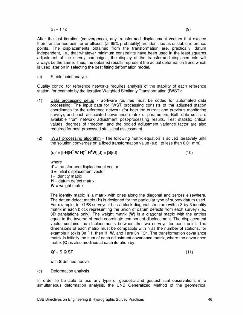
LSB Directives on Engineering & Hydrographic Survey Practices 46
p i = 1 / d I (9)
After the last iteration (convergence), any transformed displacement vectors that exceed their transformed point error ellipses (at 95% probability) are identified as unstable reference points. The displacements obtained from the transformation are, practically, datum independent, i.e., that whatever minimum constraints have been used in the least squares adjustment of the survey campaigns, the display of the transformed displacements will always be the same. Thus, the obtained results represent the actual deformation trend which is used later on in selecting the best fitting deformation model. (c) Stable point analysis Quality control for reference networks requires analysis of the stability of each reference station, for example by the Iterative Weighted Similarity Transformation (IWST): (1) Data processing setup - Software routines must be coded for automated data
processing. The input data for IWST processing consists of the adjusted station coordinates for the reference network (for both the current and previous monitoring survey), and each associated covariance matrix of parameters. Both data sets are available from network adjustment post-processing results. Test statistic critical values, degrees of freedom, and the pooled adjustment variance factor are also required for post-processed statistical assessment.
(2) IWST processing algorithm - The following matrix equation is solved iteratively until
the solution converges on a fixed transformation value (e.g., to less than 0.01 mm).
(d)' = [I-H(HT W H)-1 HTW](d) = [S](d) (10)
where d' = transformed displacement vector d = initial displacement vector I = Identity matrix H = datum defect matrix W = weight matrix The identity matrix is a matrix with ones along the diagonal and zeroes elsewhere. The datum defect matrix (H) is designed for the particular type of survey datum used. For example, for GPS surveys it has a block diagonal structure with a 3 by 3 identity matrix in each block representing the union of datum defects from each survey (i.e., 3D translations only). The weight matrix (W) is a diagonal matrix with the entries equal to the inverse of each coordinate component displacement. The displacement vector contains the displacements between the two surveys for each point. The dimensions of each matrix must be compatible with n as the number of stations, for example if (d) is 3n ´ 1, then H, W, and I are 3n ´ 3n. The transformation covariance matrix is initially the sum of each adjustment covariance matrix, where the covariance matrix (Q) is also modified at each iteration by:
Q' = S Q ST (11)
with S defined above.
(c) Deformation analysis In order to be able to use any type of geodetic and geotechnical observations in a simultaneous deformation analysis, the UNB Generalized Method of the geometrical

LSB Directives on Engineering & Hydrographic Survey Practices 47
analysis could be adopted. The method is applicable to any type of geometrical analysis, both in space and in time, including the detection of unstable reference points and the determination of strain components and relative rigid body motion within a deformable body. It permits using different types of surveying data (conventional, GPS, and geotechnical/structural measurements. It can be applied to any configuration of the monitoring scheme as long as approximate coordinates of all the observation points are known with sufficient accuracy. The approach consists of three basic processes:
• identification of deformation models;
• estimation of deformation parameters;
• diagnostic checking of the models and final selection of the "best" model.

LSB Directives on Engineering & Hydrographic Survey Practices 48

LSB Directives on Engineering & Hydrographic Survey Practices 49

LSB Directives on Engineering & Hydrographic Survey Practices 50

LSB Directives on Engineering & Hydrographic Survey Practices 51