ls100/110 accessory decoder - dccconcepts · accessory decoder ls 100/110 1 digital plus accessory...
TRANSCRIPT

Accessory Decoder LS 100/110 1
DIGITAL plus
Accessory decoders are the link between your NMRA DCCsystem and your function devices (that is turnouts, signals,uncouplers, etc.) on your model train layout.Accessory decoders receive commands sent from the commandstation via the power station and activate the drives of turnoutsor other switching devices. For DIGITAL plus systems theseswitching commands are activated from input devices, such as,hand held controller LH100, tower cab LW100, interface LI100 ortranslation module LC100 (in connection with another,compatible digital system).+Dimensions: approximately 3.5 x 3.5” (90 x 90 mm)
LS100/110Accessory DCC DecoderArt. Nr. 11100 / 11110January 1999
upgraded version 2.2
Submitted for NMRAConformance testing

2 Accessory Decoder LS 100/110
Whats new in the upgraded LS100/110?
A push button and an LED have been added to theLS100/110 to make programming easier. Direct CV mode isnow supported in service mode and a selectable flashing ratehas been added.LED:Whenever the LS100/110 has received information destinedfor it, the LED will light up for a certain amount of time. Thisallows you to very easily verify that your LS100/110 isreceiving information, and thus is correctly connected. If you,for instance, have called up the turnout address on the handheld controller and press the + or - keys, and keep thempressed, then the LED will flicker or stay lit. If you release thekey, then the LED will also go out again. If this is not the case,then you may have selected the wrong address on the LH100,or the connection from the LV101 to the LS100/110 is notcorrect.The LED is also used as a display during programming withthe push button.Push button:The push button allows you to reprogram the address of aninstalled LS100/110. You can also reset it to the factorysettings. The LED here serves to indicate the programmingprocess.Selectable flashing rate:In the previous version, the flashing rate was permanentlypreset to 2 Hz. Now you have a range of 4 to 0.5 Hz.available.
Special noteAccessory decoders LS100 and LS110 share this operationmanual. Unless noted, the text applies to the LS100 as well asLS110. When describing features, connections, operationalsteps, etc. that apply to only one of the accessory decoders,only the decoder in question is named.

Accessory Decoder LS 100/110 3
DIGITAL plus
Specifications of LS100/LS110Up to 4 function devices each with a twin output can beconnected to each LS100/LS110. Power for these functiondevices can by supplied by the track power or through anexternal power supply. Each function device output can have itscharacteristics individually set (by programming). In this way youcan program each output with a variable pulse duration, avariable flashing operation or to a constant operation,. Thisallows the direct connection of lightbulbs or LEDs withoutadditional relays.
The LS100 also has a connection for the feedback bus of theDIGITAL plus system. If the feedback bus is connected, then theposition of turnouts can be sent back to the system when usingsuitable turnout drives. It is then possible to display a turnoutbeing thrown by either DCC or by hand.
Electrical specifications:
Supply voltage:8 - 18V AC or pulsing DC8 - 25V pure DC (battery, lab power supply).Current load capacity:individualoutput:
1.7A continous,3 A peak (max. 20 sec.)
wholedecoder:
1.7A continous, as the sum of alloutputs.
3A peak (max. 20 sec.)
More about settings the outputsPulse output:
Pulse output means that the output is on (active) for at least aslong as a switching command is sent to LS100/LS110. Theswitching command is for example sent to LS100/LS110 aslong as you keep the ‘+’ or ‘-’ key pressed on LH100.
The time that the function device output remains active afterreleasing the key—the pulse duration—is determined by aprogrammed numeric value. If during the activation time of this

4 Accessory Decoder LS 100/110
pulse duration a new switching command is received by theLS100/110, the output remains active for another pulseduration.
Constant output:By pressing the ‘+’ key on the LH100, the function deviceoutput + is activated and remains active until the ‘-’ key ispressed at which time the - output is activated. Thus either the+ or - terminal of an output is active, the output operates as atoggle switch:
For example, if you were to connect a red lightbulb of a signalto an output’s + terminal, and the green lightbulb to the -terminal, then when you press the ‘+’ key, the red lightbulb willbe on (the signal shows ‘stop’). If you press the ‘-’ key, then thegreen lightbulb is on (the signal shows ‘go’). This avoids theneed to use an additional relay on light signals.
Flashing:In this mode an output’s + and - terminals are activatedalternatingly.
This mode of operation is suited for connecting the flashinglights at a train crossing or signal. The flashing rate isprogrammable; see the section “Programming the settings ofan output” for more information.
General notes: Only one of the output pairs on an LS100/110 isactive at any one time. For example if during pulse or constantoperation the + terminal is active and the - output is activated,then the + terminal goes inactive, regardless of whether thepulse duration time is up or not. This applies in thecorresponding manner when the - terminal is activated first andthe + terminal is then activated.
Caution!
When programming the outputs, please note that depending onpulse duration, or with constant operation, several outputs maybe active at the same time. With all the connected power users,you must then not exceed the maximum total current loadcapacity of 3A for the accessory decoder.

Accessory Decoder LS 100/110 5
DIGITAL plus
Installing the accessory decoder LS100/LS110
Connecting the LS100/LS110 to a power station and/orseparate power supply lineBefore you connect your LS100/LS110 to your NMRA DCCsystem or the power supply line, you must turn off your DCCsystem and disconnect the power supply (unplug the transformerfrom wall outlet). There are two options for connecting yourLS100/LS110: The first option uses the power supplied by your
6 Accessory Decoder LS 100/110
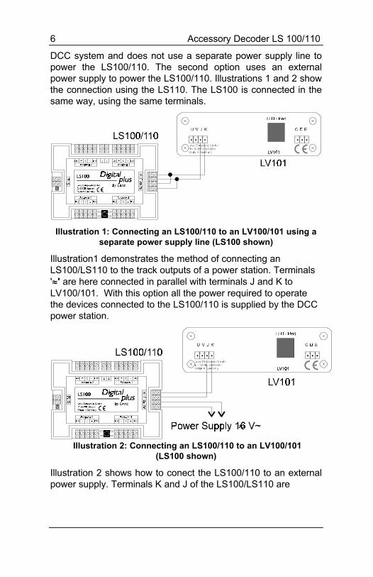
DCC system and does not use a separate power supply line topower the LS100/110. The second option uses an externalpower supply to power the LS100/110. Illustrations 1 and 2 showthe connection using the LS110. The LS100 is connected in thesame way, using the same terminals.
Illustration 1: Connecting an LS100/110 to an LV100/101 using aseparate power supply line (LS100 shown)
Illustration1 demonstrates the method of connecting anLS100/LS110 to the track outputs of a power station. Terminals'≈≈' are here connected in parallel with terminals J and K toLV100/101. With this option all the power required to operatethe devices connected to the LS100/110 is supplied by the DCCpower station.
Illustration 2: Connecting an LS100/110 to an LV100/101(LS100 shown)
Illustration 2 shows how to conect the LS100/110 to an externalpower supply. Terminals K and J of the LS100/LS110 are

Accessory Decoder LS 100/110 7
DIGITAL plus
Illustration 3: Connecting the feedback bus on LS100

8 Accessory Decoder LS 100/110
connected to the corresponding terminals on a power stationLV100/LV101. Terminals ‘≈≈‘ are connected to a transformer with16V AC.
Connecting the LS100 to the feedback bus of LZ100(LS110 only)Terminals R and S are connected to the corresponding terminalson command station LZ100. Please refer to Illustration 3.
All feedback capable devices are connected in parallel to thefeedback bus, as shown. Since each device has its ownaddress, it does not matter in what order the devices areconnected.
Of course you can use accessory decoder LS100 and feedbackencoder LR100 in any combination. You just need to make surethat you do not assign any address twice. Information aboutshared addresses is found in the sections “Programmingaddress and settings of the outputs” and “Shared addresses ofLS100/110/120 and LR100” later on in this manual.
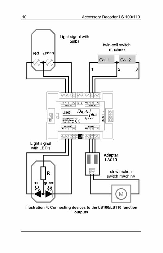
Connecting devices to the function outputsConnecting various devices to the function outputs is shown inillustration 4. Here are some additional explanations:
Connecting twin-coil turnout drivesThe common wire of the two coils (2) is connected with terminal‘C’. The wire from coil 1 (1) is connected with terminal ‘+’; theone from coil 2 (3) with terminal ‘-’. Depending on the design ofthe turnout drive, activating the ‘+’ terminal will result for instancein the turnout going to the ‘diverge’ position. If that is not howyou planned it, then switch the connections at terminals ‘+’ and ‘-’.

Accessory Decoder LS 100/110 9
DIGITAL plus
In the following table the common wire colors from some trackmanufacturers, is matched to the wire numbers in Illustration 4.
Wire #: 1 2 3
ROCO red black green
Arnold blue grey purple
Fleischmann beige black brown
Trix yellow black green
Märklin blue yellow blue
Connecting light signals with lightbulbs or LEDsIf you wish to connect the outputs to lightbulbs or LEDs, thenprogram the corresponding outputs on LS100/LS110 to constanton. You can then connect the lightbulbs or LEDs (using aresistor) directly to the outputs of LS100/LS110. If you use theseparate AC supply, the digital current will not be used.
Information on programming settings is found in the section“Programming the settings of an output” later on in this manual.
In Illustration 4 the connection of a signal’s lightbulbs is shown inthe upper left and the connection of LEDs in the lower left.
Important:
When connecting a LED, please remember that terminal ‘C’ ispositive. You must therefore connect the cathodes of the LEDsin the signal with terminals ‘+’ and ‘-’.
When using LEDs, a current limiting resistor is necessary.Please determine if this resistor is already installed in your LEDsignal.
If that is not the case, then with a supply voltage of 16V AC youneed to use a current limiting resistor of 1.5 kOhm. If the LED isnot bright enough with that, then try lowering the resistor value(1kOhm). If the LED is too bright, use a larger resistor value. Inthe illustration this resistor is indicated with ‘R’.
10 Accessory Decoder LS 100/110
Illustration 4: Connecting devices to the LS100/LS110 functionoutputs
Accessory Decoder LS 100/110 11
DIGITAL plus
Connecting a motorized turnout driveTo connect motorized turnout drives, you need adapter LA010(Illustration 4 lower right). This adapter changes the polarity ofthe motor connections to the required direction as needed.
By using this adaptor, you avoid complicated relay set-ups forcontrolling a motorized drive.
For motorized drives program the outputs to pulse operation andset the pulse duration such that the motor remains on until itreaches the end of its stroke. With stall current turnout motorsthe pulse duration can be set to constant on.
Information about programming settings is found in the section“Programming the address and settings” later on in this manual.
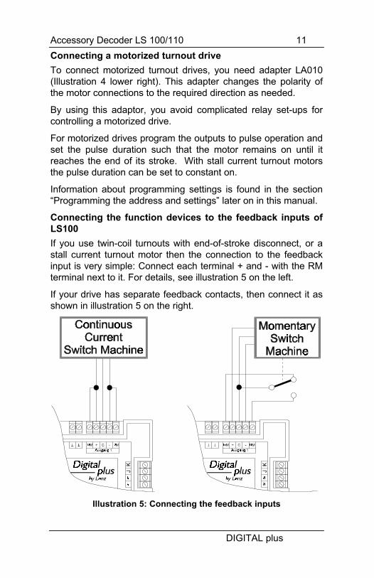
Connecting the function devices to the feedback inputs ofLS100If you use twin-coil turnouts with end-of-stroke disconnect, or astall current turnout motor then the connection to the feedbackinput is very simple: Connect each terminal + and - with the RMterminal next to it. For details, see illustration 5 on the left.
If your drive has separate feedback contacts, then connect it asshown in illustration 5 on the right.
Illustration 5: Connecting the feedback inputs

12 Accessory Decoder LS 100/110
For information on how to read the turnout position on hand heldcontroller LH100 or another device, please refer to the manualfor that device.
Using external control on conjunction with the LS100/110
The LS100/LS110 version 2 provides the ability to control thefunction devices connected to LS100/LS110 either digitally orwith an external push button (or REED switch). This is doneusing the terminal marked ‘⊥⊥‘. Illustration 6 shows you how towire the external push buttons and/or REED switches.
Illustration 6: Connecting external controls

Accessory Decoder LS 100/110 13
DIGITAL plus
It is required that the output to be optionally controlled by anexternal push button not be set to flashing or constant operationand that the function device being controlled is equipped withend-of-stroke disconnect.
Shown is the typical twin-coil drive for signals or turnouts. Thetwo coils are connected with the + and - terminals on theaccessory decoder. The illustration shows LS100, on LS110connections are made in the same manner to the sameterminals. In addition both buttons K1 and K2 are connected. Ifyou press button K1, then coil 1 is activated; if you press buttonK2, then coil 2 is activated. This way, you can throw the turnout(or switch the signal) digitally using LS100/LS110, or with thebuttons K1 and K2.
IMPORTANT:The ⊥⊥ terminals of different LS100/LS110’s must not be
connected with each other. This is not a common ground!You must only use potential free (isolated) contacts (for
instance REED switches). The ROCO control track 42518 isanother suitable example.
Programming address and settings of outputsFirst you must determine which numbers the function devicesthat will be connected are to ‘listen’ to; you must program theaddress of the accessory decoder. In the second step, youdetermine the settings of the outputs.
Standard settings of accessory decoder LS100/LS110From the factory LS100/LS110 is programmed to turnoutnumbers 1 to 4. The outputs are set to pulse operation with theshortest pulse duration. These settings are referred to asstandard settings.
Explanations of the turnout addressesNote that LS100/LS110 is always programmed to a group of 4turnout addresses. This is for example the numbers 1 to 4, 5 to8, 9 to 12 and so on up to 253 to 256. It is not possible toprogram a LS100/LS110 to the turnout numbers 3, 4, 5 and 6,since these turnout numbers belong to two different groups.

14 Accessory Decoder LS 100/110
The shared address area of LS100/LS110/LS120 and LR100Information about the positions of turnouts and signals fromaccessory decoder LS100/LS110 and feedback encoder LR100occupies the same memory locations in the command station.Information from the feedback encoder with addresses 1 to 63overlaps information from turnouts 1 to 256.
Even non-feedback capable LS110 turnout positions have thelast command sent stored in this address area. Since nopositive feedback is available, this information may not matchthe actual turnout position.
For each turnout address there are 2 feedback positions in thecommand station; for each feedback encoder, there are 8feedback positions in the command station. The overlap isdisplayed in table 5.
Example:
If you have programmed an accessory decoder LS100 toaddresses 5, 6, 7 and 8, then it occupies the feedback positions9 to 16 in the command station. You can therefore not use afeedback encoder with address 2, since this would occupy thesame feedback numbers in the command station.
Programming the address of LS100/LS110 using theprogramming buttonThis is a process where you can program LS100/LS110 to aturnout address without using the programming output .
This process is suitable whenever you do not need any particularsettings for the outputs and/or the accessory decoder is alreadyinstalled and needs to be reprogrammed to another address.You can use any device that can send a acessory decodercommand such as a LH100 hand held controller or LW100Tower Cab.
For these instructions we assume that command station, powerstation and hand held controller or tower cab all are correctlyconnected with each other, and in operation (see manuals of thedevices).

Accessory Decoder LS 100/110 15
DIGITAL plus
Press the programming button on the LS100/LS110 and keep itpressed until the LED lights up and stays lit (this takes a fewseconds). Now release the button. The LED stays on. TheLS100/LS110 now will take its new address from the first DCCaccessory decoder command it receives.
To correctly program the LS100/LS110 at this point ensure thatno device is sending commands without your knowledge. Thesecommands could for instance come via the interface from acomputer program that is running, a switching chain from towercab LW100 or even from another operator on the layout.
Now intentionally generate the switching command needed forprogramming:
with hand held controller LH100:Switch LH100 over to operation mode ‘Throw turnout’ (Keysequence F, 5). Enter one of the 4 turnout addresses in thegroup that you want to program LS100/LS110 to. Confirm theentry with the ‘enter’ key. Now press the ‘+’ or ‘-’ key on thehand held controller and thereby send a switching command.
with tower cab LW100:Press the red or green key of one of the 4 turnouts in the groupthat you want to program LS100/LS110 to. You may need tofirst set LW100 to the needed group (see the manual forLW100). With each pressing of the red or green key, youcause a switching command to be sent.
The turnout address sent in the switching command is nowpermanently stored in the LS100/LS110. Verify that theprogramming took place by observing the LED goes out and thecorrect turnout is thrown (if connected). The LS100/LS110 isnow back in normal operation mode.
Programming LS100/LS110 to the standard settings usingthe programming buttonPress the programming button and keep it pressed. Afterapproximately 5 seconds the LED is lit constantly. Continue topress the button. After another 5 seconds the LED startsflashing. Continue to press the button pressed until the LEDturns off again. When this ocurs the operation is completed

16 Accessory Decoder LS 100/110
Programming address and settings through theprogramming output of LZ100Address and other settings of LS100/LS110 are stored in socalled “registers”, abbreviated “R”. These registers can beimagined as a sort of notepad that can have new entries put onthem again and again. The written entries remain stored evenafter the power is turned off.
Assignment of registersLS100/LS110 has 6 registers, that are used as follows:
Reg CV AltCV
used for allowed range ofvalues
1 1 513 address 1 - 2562 3 515 settings output 1 0 - 15; 32; 33 - 473 4 516 settings output 2 0 - 15; 32; 33 - 474 5 517 settings output 3 0 - 15; 32; 33 - 475 6 518 settings output 4 0 - 15; 32; 33 - 477 7 519 version number 2.28 8 520 manufacturer ID 99- 29 541 Configuration 128
Table 1: Assignment of registers
The value stored in R1 thus determines the address, the‘number’ with which the connected function devices areaddressed.
R†2†to†5 behave the same: The values stored here determinethe settings of the outputs. From table 2 you see the values thatneed to be entered for a desired setting of an output:
Value Setting0 - 15 Pulse output, variable
pulse duration32 Constant output
33 - 47 Flashing, variable rate
Table 2: Settings of the outputs
Values other than the ones listed are not allowed and will lead torandom results.

Accessory Decoder LS 100/110 17
DIGITAL plus
The pulse duration is determined by the following values:
value pulse duration(seconds)
value pulse duration(seconds)
0 0.1 8 2.01 0.2 9 3.02 0.3 10 4.03 0.5 11 6.04 0.6 12 8.05 0.8 13 106 1.0 14 127 1.5 15 15
Table 3: Setting pulse duration
The flashing rate is determined by the following values:
Value flashing rate (Hz) Value flashing rate (Hz)33 4 41 2.034 3.75 42 1.7535 3.5 43 1.536 3.25 44 1.2537 3.0 45 1.038 2.75 46 0.7539 2.5 47 0.540 2.25
Table 4: Setting the flashing rateThe decoder version number is contained in R7. R8 contains themanufacturer ID, which for Lenz Elektronik is 99. Both registerscan only be read, and can not be overwritten.
Connecting the LS100/LS110 to the programming output ofa command stationWhen the accessory decoder is to be programmed using theprogramming output of the command station, we recommendthat you do all the programming before installation. For thecommand station to be able to recognize successfulprogramming, please connect a turnout motor or a lightbulb (notan LED!) to an output that is not set to constant on or flashingoperation. If you do not do this, you will get an error message“ERR02” (decoder not found) on the LH100.

18 Accessory Decoder LS 100/110
Illustration 7: Connecting LS100/LS110 to theprogramming output of LZ100
To program address and settings you need your commandstation LZ100, hand held controller LH100 and a transformerwith 16V AC output to supply power for LZ100. TheLS100/LS110 is programmed using the programming output ofcommand station LZ100. (Note any other system capable ofDirect CV mode or Register mode programming can alsosucessfuly program an LS100/LS110.)
To do this, connect terminals J and K, as well as the terminalsfor the AC supply (•) of the LS100/LS110 to the programmingoutput (terminals P and Q) of the LZ100 command station.
Enter programming mode, as described in the manual for theLH100.
Programming using LH100 with software version 2.1
Please proceed as follows:Key On the display you see
(flashes)
Confirm again with the ‘Enter’ key.

Accessory Decoder LS 100/110 19
DIGITAL plus
Next LH100 will show you the most recently chosenprogramming mode. Press the ‘+’ key repeatedly until thedisplay shows
Confirm this display with the ‘Enter’ key.
Now you must indicate which register you want to program. Intable 1 you can see which register is responsible for whichfunction.
Note: There is an error in the LH100 to be aware ofIf you select the “CV” mode, the LH100 starts an address
search . At its completion, you receive the display "LENZ -d".After pressing any key the address is displayed “SAD xx”,
where xx is the decoders address. If you now again press anykey other than the 'CL" key, the LH100 will show “R*_” whichis in error as the LH100 is actually still in CV mode and not inREG mode as the display indicates. To return to REG mode,please press the “Esc” key repeatedly until the display again
shows “PROG”, press enter and then choose the “REG”mode using the "+" key.
Programming the turnout address
Proceed to programming mode as described above.
Let’s assume that you want to program LS100/LS110 to turnoutaddresses 9, 10, 11 and 12.
Select register 1 as the register to program, since the address isstored at this position (see table 1).
On LH100 enter one of the four turnout addresses, to which youwant to program LS100/LS110. In this example that is 9, 10, 11or 12.
Start the programming by pressing the ‘enter’ key. LS100/LS110will now be programmed to turnout numbers 9 to 12. Output 1will be addressed with turnout address 9, output 2 with address10 and so on. On the hand held controller you get the message

20 Accessory Decoder LS 100/110
“ERR 02”. Ignore this message, since LS100/LS110 is not ableto confirm successful programming to the command station.Neither can you read out the values stored in the memorylocations.
Programming the settings of an outputIn the following examples the settings of output 1 ofLS100/LS110 are programmed. Outputs 2, 3 and 4 areprogrammed in the same manner, only with the correspondingchange of the storage location.
First connect the accessory decoder to the programming outputof the command station, as described above, and change intoprogramming mode with the hand held controller.
Select register 3. In this position the settings of output 1 arestored (see Table 1).
Example 1: Setting pulse operation with shortest pulse duration.
As you see from tables 2 and 3 above, you must enter thenumber 1 on hand held controller LH100 as the value to beprogrammed. Then start the programming with the ‘Enter” key.
Example 2: Setting to constant on:
Enter 32 as the value to be programmed on hand held controllerLH100 (see Table 2). Start the programming sequence with the‘Enter’ key.
By entering other values from table 3, you can choose to definethe other settings.

Accessory Decoder LS 100/110 21
DIGITAL plus
Table 5 Feedback addresses / turnout addresses:F-Feedback address; T-Turnout address, FE-Feedback information in the command stationF FE T F FE T1 1 to 8 1 to 4 33 257 to 264 129 to 1322 9 to 16 5 to 8 34 265 to 272 133 to 1363 17 to 24 9 to 12 35 273 to 280 137 to 1404 25 to 32 13 to 16 36 281 to 288 141 to 1445 33 to 40 17 to 20 37 289 to 296 145 to 1486 41 to 48 21 to 24 38 297 to 304 149 to 1527 49 to 56 25 to 28 39 305 to 312 153 to 1568 57 to 64 29 to 32 40 313 to 320 157 to 1609 65 to 72 33 to 36 41 321 to 328 161 to 164
10 73 to 80 37 to 40 42 329 to 336 165 to 16811 81 to 88 41 to 44 43 337 to 344 169 to 17212 89 to 96 45 to 48 44 345 to 352 173 to 17613 97 to 104 49 to 52 45 353 to 360 177 to 18014 105 to 112 53 to 56 46 361 to 368 181 to 18415 113 to 120 57 to 60 47 369 to 376 185 to 18816 121 to 128 61 to 64 48 377 to 384 189 to 19217 129 to 136 65 to 68 49 385 to 392 193 to 19618 137 to 144 69 to 72 50 393 to 400 197 to 20019 145 to 152 73 to 76 51 401 to 408 201 to 20420 153 to 160 77 to 80 52 409 to 416 205 to 20821 161 to 168 81 to 84 53 417 to 424 209 to 21222 169 to 176 85 to 88 54 425 to 432 213 to 21623 177 to 184 89 to 92 55 433 to 440 217 to 22024 185 to 192 93 to 96 56 441 to 448 221 to 22425 193 to 200 97 to 100 57 449 to 456 225 to 22826 201 to 208 101 to 104 58 457 to 464 229 to 23227 209 to 216 105 to 108 59 465 to 472 233 to 23628 217 to 224 109 to 112 60 473 to 480 237 to 24029 225 to 232 113 to 116 61 481 to 488 241 to 24430 233 to 240 117 to 120 62 489 to 496 245 to 24831 241 to 248 121 to 124 63 497 to 504 249 to 25232 249 to 256 125 to 128 64 505 to 512 253 to 256

22 Accessory Decoder LS 100/110
Trouble shootingProblem Cause SolutionTurnout does not throw, theLED does not flicker while a
Wrong turnout addressentered.
Enter the correct turnoutaddress.
switching command is beingsent (a switching command isalways sent when you pressthe ‘+’ or ‘-’ key on LH100 while
Connection between commandstation and power station orbetween power station andaccessory decoder is broken.
Check and correct theconnections.
in switching mode, or when onLW100 one of the red or greenkeys is pressed).
A power station has turned offdue to a short circuit or userinitiating an EMERGENCYOFF.
Remove cause of the shortcircuit, in case of an overload,divide the layout into severalsupply sections.
External power supply is notconnected (terminals ‘≈≈' are notconnected).
Connect the power supply(see illustrations 2 and 1).
Turnout does not throw, but theLED flickers while a switchingcommand is being sent.
Turnout or signal drive is notcorrectly connected, or isdefective.
Test and correct theconnections.
A called up LS100 is not shownas a feedback capable decoder(no R shows in the LH100display).
Feedback bus is not connectedor the wires R and S areswitched.
Connect the feedback bus, orcorrect the wires.
When calling up aLS100/LS110 on LH100, thefollowing displayshows:
The entered address is notoccupied by an accessorydecoder, but by a feedbackencoder.
Enter the correct turnoutaddress. Check if youaccidentally programmedoverlapping addresses (see“The shared address area ofLS100/LS110/LS120 andLR100) earlier in this manual.
When programming from theprogramming output of thecommand station, you get themessage “ERR 02” on thehand held controller.
The command station cannottest for successfulprogramming, since no load isconnected to the output ofLS100/LS110.
Connect a turnout drive orlightbulb to one of the outputsof LS100/LS110. See thesection “Programmingaddress and settings throughthe programming output ofLZ100” earlier in this manual.
When programming from theprogramming output of thecommand station, you get themessage “ERR 02” on thehand held controller.
Connection between theprogramming output of thecommand station (terminals Pand Q) and LS100/LS110 is notcorrect.
Test and correct allconnections.

Accessory Decoder LS 100/110 23
DIGITAL plus
Lenz GmbH does everything it can do to ensure that its productsare free from defects and will operate for the life of your modelrailroad equipment. From time to time even the best engineeredproducts fail either due to a faulty part or from accidentalmistakes in installation. To protect your investment in DigitalPlus products. Lenz GmbH offers a very aggressive 10 yearLimited Warranty.
This warranty is not valid if the user has altered, intentionallymisused the Digital Plus product, or removed the product'sprotection, for example the heat shrink from decoders and otherdevices. In this case a service charge will be applied for allrepairs or replacements. Should the user desire to alter a DigitalPlus Product, they should contact Lenz GmbH for priorauthorization.
Year One: A full repair or replacement will be provided to theoriginal purchaser for any item that that has failed due tomanufacturer defects or failures caused by accidental userinstallation problems. Should the item no longer be producedand the item is not repairable, a similar item will be substitutedat the manufacturers discretion. The user must pay for shippingto an authorized Lenz GmbH warranty center.
Year 2 and 3: A full replacement for any item will be providedthat has failed due to manufacturer defects. If the failure wascaused by accidental user installation or use, a minimal servicecharge may be imposed. Should the item no longer be producedand the item is not repairable, a similar item will be substituted atthe manufacturers discretion. The user must pay shipping toand from the authorized Lenz GmbH warranty center during thisportion of the warranty period.
Year 4-10: A minimal service charge will be placed on eachitem that has failed due to manufacturer defects and/oraccidental user installation problems. Should the item no longerbe produced and the item is not repairable, a similar item will besubstituted at the manufacturers discretion. The user must payshipping to and from the authorized Lenz GmbH warranty centerduring this portion of the warranty period.

24 Accessory Decoder LS 100/110
Please contact your dealer or authorized Lenz GmbH warrantycenter for specific instructions and current service charges priorto returning any equipment for repair.
Hüttenbergstraße 2935398 Gießen, GermanyHotline: 06403 900 133
Fax: 06403 5332http://www.lenz.com
Lenz Agency of North AmericaPO Box 143
Chelmsford, MA 01824ph/fax: 978 250 [email protected]
This equipment complies with Part 15 of FCC Rules. Operation is subject to thefollowing two conditions: (1) this device may not cause harmful interference, and(2) this device must accept any interference received, including interference thatmay cause undesired operation.
Please save this manual for future reference!
© 1999 Lenz GmbH, All Rights Reserved