lrv operations handbook appendix a ... lunar roving vehicle operations handbook contract nas8-25145...
TRANSCRIPT

NATIONAL
j b
AERONAUTICS AND SPACE ADMINISTRATION
/
LRV OPERATIONS
HANDBOOK
APPENDIX A
(PERFORMANCE DATA)
:i:i:i:i:"(NASA-TM-X-66816) LRV
:::::::::_PP_.DIXA (P_FO_ANC_1::::::::,,,.,,o,,
,,,.,,,•.
1:::::::::.:.:.:.:,'o',',',°, ....,.,...o.,,,
%',%°,,,.,','.°o,,%"
%O.,o,,,,,°,,o,O,,o-,"
%-,-,,,-,o,',',',,o,o'
,,,,,,,,•,.,o°,,O.Oo,,"
,o•,O,,,,.,.'°,,-,,,,,"
• °.°°.°O,o%-,.o%°
::::::::::::::::::::::• ,',',','.'°'.'.'o°,',
• ,'•°o',','.'.','.','°
• ,'.','.',°.'.',','.'.
• ,','.°o',','°'o'.'.°.
::::::::::::::::::::::
OPEPATIONS HANDBOOK
DATA) (NASA) 120 p
REVISION 1
APRIL 19, 19 1 I
00/98
N75-7_052]Unclas
17581
_.,.',_7_ MANNED SPACECRAFT CENTER
, ;_y HOUSTON,TEXAS
° ° ° ° ° ° °',°o°,°°,°o°o°°,o
o°•°°,°o•°,°°°°°°o°'°o•°,°,%°.,°',
,.,...,,.,,
,.,,,,,.,,,o,-,,,.,..
",,.,o'o,.,,'o-,-.Oo.,,
:::::::::::::::::::::::,,o'•'.,,%',',',,o,,',
":+7:.:.:':':-:.:.:.

LSOO6-OO2-2H
LUNAR ROVING VEHICLE
OPERATIONS HANDBOOK
CONTRACT NAS8-25145
APPROVED:
I
PREPARED BY THE BOEING COMPANY
LRV SYSTEMS ENGINEERING
HUNTSVILLE, ALABAMA

PREFACE
This document is the first revision issue of the Appendix A
(Performance Data) to the LRV Operations Handbook. This appendix
will be maintsined on a controlled bssis by the Systems Engineering
Division of the Apollo Spacecraft Program Office, with change pages
issued as required.
It is requested that any comments to the data content, require-
ments for additional data, and distribution changes be sent to PD4/
Mr. J. W. Mistrot, extension 4667.

REV
LTR
il i
AMEND
NO.
I
DES(_IPTION
REVISIONS
DATE

LSOO6-OO2-2HLUNAR ROVINGVEHICLEOPERATIONSHANDBOOK
APPENDIX A
SECTION
1.0I.I1.21.31.4
2.02.12.22,32.42.52.62.72.82.92.10
3.03.13.23.33.43.5
3.63.73.83.93.10
4.04.14.24.34.4
5.05.15.25.35.4
b.O6.1
TABLE OF CONTENTS
INTRODUCTIONPURPOSECONTENTAMENDMENTSSELECTED ABBREVIATIONS AND ACRONYMS
CONFIGURATIONCHASSIS CONFIGURATIONSUSPENSIONSYSTEM CONFIGURATIONSTEERING SYSTEM CONFIGURATIONTRACTION DRIVE CONFIGURATIONWHEELCONFIGURATIONCREWSTATION CONFIGURATIONPOWERSYSTEMCONFIGURATIONNAVIGATION SYSTEM CONFIGURATIONTHERMALCONTROLCONFIGURATIONPAYLOAD INTERFACES
CONSTRAINTS AND OPERATIONAL LIMITATIONSCHASSIS SUBSYSTEM CONSTRAINTSSUSPENSION SUBSYSTEM CONSTRAINTS
MOBILITY SUBSYSTEM CONSTRAINTSELECTRICAL POWER SUBSYSTEM CONSTRAINTSNAVIGATION SUBSYSTEM CONSTRAINTSDISPLAY AND CONTROLS SUBSYSTEM CONSTRAINTSCREW STATION SUBSYSTEM CONSTRAINTSVEHICLE DYNAMIC OPERATION CONSTRAINTSPARKING CONSTRAINTSTHERMAL CONSTRAINTS
SUBSYSTEMPERFORMANCEDATAMOBILITY SUBSYSTEMPERFORMANCEELECTRICAL SUBSYSTEMPERFORMANCENAVIGATION SUBSYSTEMPERFORMANCEDISPLAYS AND CONTROLSSUBSYSTEMPERFORMANCE
VEHICLE PERFORMANCE DATA
VEHICLE DYNAMIC RESPONSERANGE, SPEED, LURAIN CAPABILITYTHERMAL PERFORMANCECONTROLLABILITY
SPECIFIC VEHICLE DATALRV-I
PAGE
A-IA-IA-IA-IA-I
A-2A-2A-2A-2A-2A-2A-2A-3A-3A-3A-3
A-23A-23A-23A-23A-23A-25A-25A-26A-26A-26A-26
A-46A-46A-59A-67A-75
A-79A-79A-82
A-83A-83
A-93A-93
Mission Basic Date 2/5/71 Cnange Date 4119/71

LSOO6-OO2-2HLUNAR ROVING VEHICLE
OPERATIONS HANDBOOKAPPENDIX A
LIST OF FIGURES
FIGURE NO. PAGE
2-I
2-22-32-4
2-52-62-72-82-92-102-112-122-132-143-I3-23-33-43-5
3-6
3-7
3-I0
3-11
3-12
3-13
LRV CONFIGURATION WITHOUT STOWED PAYLOADLRV DIMENSIONSLRV CHASSISLRV SUSPENSION SYSTEM
LRV STEERING SYSTEMLRV TRACTION DRIVELRV WHEELLRV WHEEL DEFLECTION VS LOADLRV DRIVE CONTROLLRV CREW STATION COMPONENTSLRV BATTERY AND DUST COVER ASSEMBLYLRV NAVIGATION COr_PONENTSLRV THE_IAL CONTROLPAYLOAD INTERFACESCREW STATION LIMIT LOADS (HANDHOLDS & TOEHOLDS)CREW STATION LIMIT LOADS (SEATS & FOOTRESTS)GROSS WEIGHT ALLOWABLE C.G. ENVELOPEVEHICLE STATIC STABILITYLATERAL LIMIT VELOCITY FOR OVERTURNING FROM
COLLISION WITH IMMOVABLE OBJECTLRV SLIDING LIMIT VELOCITY AS A FUNCTION OF
TURNING RADIUS AND SLOPE ANGLE FOR A 0.8COEFFICIENT OF FRICTION
LRV SLIDING LIMIT VELOCITY AS A FUNCTION OFTURNING RADIUS AND SLOPE ANGLE FOR A 0.6
COEFFICIENT OF FRICTIONLRV OVERTURNING LIMIT VELOCITY AS A FUNCTION OF
TURNING RADIUS AND SLOPE ANGLEMAXIMUM BUMP HEIGHTS WHICH CAN BE ENCOUNTERED
WITHOUT CAUSING OVERTURN AS A FUNCTION OFVELOCITY AND SLOPE
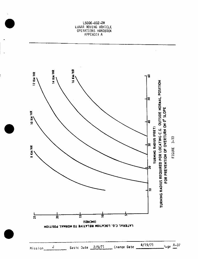
TURNING RADIUS REQUIRED FOR LOCATING C.G, OUTSIDENORMAL POSITION FOR PREVENTION OF OVERTURN ON0 ° SLOPE
TURNING RADIUS REQUIRED FOR LOCATING C.G. OUTSIDENORMAL POSITION FOR PREVENTION OF OVERTURN ONI0 o SLOPE
TURNING RADIUS REQUIRED FOR LOCATING C.G. OUTSIDENORMAL POSITION FOR PREVENTION OF OVERTURN ON20 ° SLOPE
TURNING RADIUS REQUIEED FOR LOCATING C.G. ABOVENORMAL POSITION FOR PREVENTION OF OVERTURN ON0 ° SLOPE
A-4A-5A-6A-7A-8A-9A-IOA-I 1A-12A-14A-16A-17A-18A-19A-27A-28A-29A-31A-32
A-33
A-34
A-35
A-36
A-37
A-38
A-39
A-40
Basic D_te 2/5/71 Change Date 4/19/71 ?uge oAiiM_sl0n J

LSOO6-OO2-2H
LUNAR ROVING VEHICLEOPERATIONS HANDBOOK
APPENDIX A
LIST OF FIGURES
(Continued)
FIGURE NO.
3-14
3-15
3-16
3-174-I4-24..34-4
4-5
4-6
4-7
4-8
4-9
4-10
4-11
4-12
4-134-14
4-15
4-16
4-17
TURNING RADIUS REQUIRED FOR LOCATING C.G. ABOVENORMAL POSITION FOR PREVENTION OF OVERTURN ONI0 ° SLOPE
TURNING RADIUS REQUIRED FOR LOCATING C.G. ABOVENORMAL POSITION FOR PREVENTION OF OVERTURN ON20 ° SLOPE
SAFE DRIVING CORRIDOR IN CASE_OF STEERING FAILUREAS A FUNCTION OF VELOCITY, SLOPE, AND STEERINGAPPLICATION
FARKING ORIENTATION CONSTRAINTS
VEHICLE POWER CONSt:MPTION V% SPEED - 0 ° SLOPE
VEHICLE POWER CONSUMPTION VS SPEEb - 5° SLOPE
VEHICLE POWER CONSUMPTION VS SPEED -.lO° SLOPE
LRV TRACTION DRIVE PERFORMANCE (DC MOTOR-HARMONIC
DRIVE-DRIVE CONTROLLER) FULL VOLTAGE (36 V)PERFORMANCE
BATTERY CURRENT VS SPEED
TR#.CTION DRIVE-RATE (IF TEMPERATURE INCREASE VS
SOLAR ELEW_.TION ANGLE (FRONT WHEEL)
TP,ACTION DRIVE-RATE OF TEMPERATURE INCREASE VS
ZENITH ANC_LE (LEFT FRONT WHEEL)TRACTION DRIVE-RATE OF TEMPERATURE INCREASE VS
ZFNITH ANGLE (LEFT REAR WHEEL)TRACTION DRIVE-RATE OF TEMPEP.ATURE INCREASE VS
7ENITH ANGLE (RIGHT FRONT WHEEL)TRACTION DRIVE-RATE OF TEMPERATURE INCREASE VS
ZENITH ANGLE (RIGHT RLAR WHEEL)TRACTION DRIVE-RATE OF TEMPERATURE INCREASE VS
SPEED (FRONT WHEEL)
TRACTION DRIVE-RATE OF TEMPERATURE INCREASE VS
SLOPL (FRONT WHEEL)VOLTAGE VS CURRENT DRAW PER BATTERY
BATTERY VOLTAGE VS STATE OF CHARGE
[_ATTERY RATE or- TEMrERATURE INCREASE WITF CURRENT
DRAIN (RIGHT BATTERY; i.e., BAITERY #2)B#TTERY RAIE OF TEMPERATURE INCREASE WIT_ CURI)ENT
DRAIN (LEFT BATTERY; i.e., BATTERY #l)
BATTERY RAIE OF TEf.;PFRATURE CHANGE (DIJST COVERS
OPEN, LEFT BATTERY; i.e., BAITERY #1)
PAGE
A-41
A-42
A-43
A-4_A-47A--4E
A-4t'
A-50
A-51A-52
A-53
A-5_
A-55
A-5G
A-57
A-58
A.-6_IA-61A-62
A-63
A-6._
Mission J Basic Date 2/5/71 Change Date 4/19/71 ?uge #,i_.,ii

LSOO6-OO2-2H
LUNAR ROVING VEHICLEOPERATIONS HANDBOOK
APPENDIX A
FIGURE NO.
4-18
4-194-2O4-214-224-234-24
4-254-264-27
4-28
4-295-I
5-25-35-45-5
5-65-75-85-9
6-I6-26-36-46-56-66-76-8
LIST OF FIGURES
(Continued)
PAGE
BATTERY RATE OF TEMPERATURE CHANGE (DUST COVERS A-65OPEN, RIGHT BATTERY; I.E., BATTERY #2)
DISTRIBUTION LOSSES A-66
DGU POWER CONSUMPTION A-68DGU DRIFT RATE VS TEMPERATURE A-69NAVIGATION BEARING ERROR AS A FUNCTION OF DGU DRIFT A-70SSD AZIMUTH CORRECTION FOR VEHICLE ROLL A-71CORRECTED SSD ANGLE FOR VEHICLE PITCH - SUN ANGLE lO° A-72CORRECTED SSD ANGLE FOR VEHICLE PITCH - SUN ANGLE 25° A-73CORRECTED SSD ANGLE FOR VEHICLE PITCH - SUN ANGLE 40° A-74TORQUE REQUIRED TO ROTATE HAND CONTROLLER FOR A-76
THROTTLE CONTROL
TORQUE REQUIRED TO ROTATE HAND CONTROLLER FOR A-77STEERING CONTROL
BRAKE CONTROL FORCE VS DISPLACEMENT A-78VERTICAL ACCELERATION AT LRV SEATS AS A FUNCTION OF A-80
VELOCITY AND LURAIN TYPE
LRV DAMPING POWER LOSSES A-85EFFECT OF SPEED ON LRV RANGE A-86EFFECT OF WEIGHT CHANGE ON RANGE FOR FOUR LURAIN TYPES A-87EFFECT OF WEIGHT CHANGE ON MAXIMUM VELOCITY FOR FOUR A-88
LURAIN TYPES
SLOPE CLIMBING CAPABILITY FOR VARYING C.G. LOCATION A-89STOPPING DISTANCE VS SPEED A-90POWER SPECTRAL DENSITY FOR LUNAR SURFACE ROUGHNESS A-glEFFECT OF WEIGHT CHANGE ON CONTROLLABILITY FOR FOUR A-92
LURAIN TYPES
TRACTION DRIVE CHARACTERISTICS FOR LF .DRIVEUNIT A-94TRACTION DRIVE CHARACTERISTICS FOR RF DRIVE UNIT A-95TRACTION DRIVE CHARACTERISTICS FOR LR DRIVE UNIT A-96TRACTION DRIVE CHARACTERISTICS FOR RR DRIVE UNIT A-97
METER CALIBRATION - MOTOR TEMPERATURE A-102METER CALIBRATION - BATTERY TEMPERATURE A-103GYRO DRIFT RATE, LRV-I METER CALIBRATION - AMP HOUR A-104METER CALIBRATION - VOLTS/AMPS A-105
Mission J Basic Date 215171 Cnange Date 4/19/71 Puge __Aiv

LSOO6-OO2-2HLUNARROVINGVEHICLEOPERATIONSHANDBOOK
APPENDIXA
TABLENO.
3-I
3-11
3-111
5-I
5-11
5-Ill
5-1V
6-I
6-II
6-III
6-IV
LISTOFTABLES
PAYLOADLIMITATIONS
COMPONENTTEMPERATURELIMITS
SPEEDRESTRICTIONSTOPREVENTEXCEEDINGSTRUCTURALDESIGNLOADS
VIBRATIONENVIRONMENTATLRVPAYLOADINTERFACES
LRVSTEADYSTATEPOWERCONSUMPTION
LRVSPEEDCAPABILITY
LRVCONTROLLABILITYSPEEDLIMITS
LRV-INAVIGATIONSYSTEMPOWERCONSUMPTION
LRV-IWEIGHT,C.G. ANDMOMENTSOFINERTIA
LRV-ILUNAROPERJ_TIONALWEIGHTDISTRIBUTION-STATIC,LEVELLURAINCONDITION
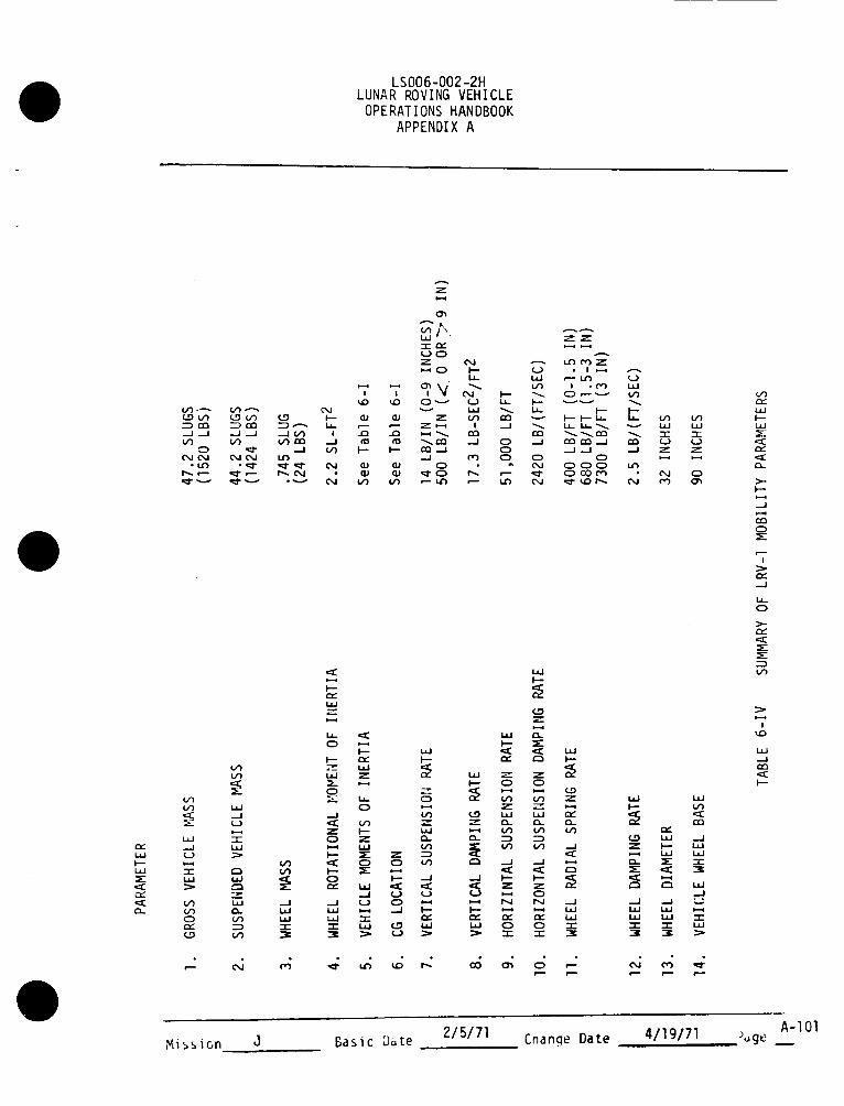
SUMMARYOFLRV-IMOBILITYPARAMETERS
PAGE
A-24
A-30
A-44
A-81
A-82
A-83
A-84
A-98
A-99
A-lO0
A-lOl
Mission J Basic Date 215171 Change Date 4119/71 Page Av

LSOO6-OO2-2HLUNAR ROVING VEHICLEOPERATIONSHANDBOOK
APPENDIX A
1.0 INTRODUCTION
I.I PURPOSE
This document is intended to supply LRV performance data necessary for missionplanning and flight control personnel to adequately plan and control operationof the LRV on the lunar surface. The data contained herein is to be used inconjunction with the LRV Operations Handbook which contains crew operatingprocedures, timelines and system description.
1.2 CONTENT
This Appendix A contains data on LRV configuration and defines constraints andoperation_limitations of the various vehicle subsystems. In addition subsystemsperformance data are provided as well as overall vehicle performance data. Thefinal section of the Appendix contains data defining constraints and performancedata unique to each individual LRV.
1.3 AMENDMENTS
Amendments to data contained in the appendix will be issued as additional databecomes available from LRV test programs and/or as more refined data becomesavailable from updated analyses. When such amendments are issued, they willbe approved and signed by the MSFC LRV Program Manager. MSFC will then trans-mit one printing master of each amendment to MSC. Reproduction and controlof amendment distribution at MSC will be accomplished by MSC.
1.4 SELEClED ABBREVIATIONS AND ACRONYMS
The following abbreviations and acronyms are used throughout this docun_nt:
DCE - Drive Controller ElectronicsDGU - Directional Gyro UnitGCTA - Ground Controlled Television AssemblyIPI - Integrated Position IndicatorKPII - Kilometers per HourLCRU - Lunar Communications Rela_yUnitLRV - Lunar Roving VehicleNSS - Navigation SubsystemPSD - Power Spectral DensityPWM - Pulse Width Modulator
SPU - Signal Processipg LlnitTBD - To be Determined
Mission J Basic Date 2/5/71 Cnange Date 4/19/71 Puge mA-I

LSOO6-OO2-2HLUNAR ROVING VEHICLEOPERATIONSHANDBOOK
APPENDIX A
2.0 CONFIGURATION
The illustrations included in this section describe the configuration of the
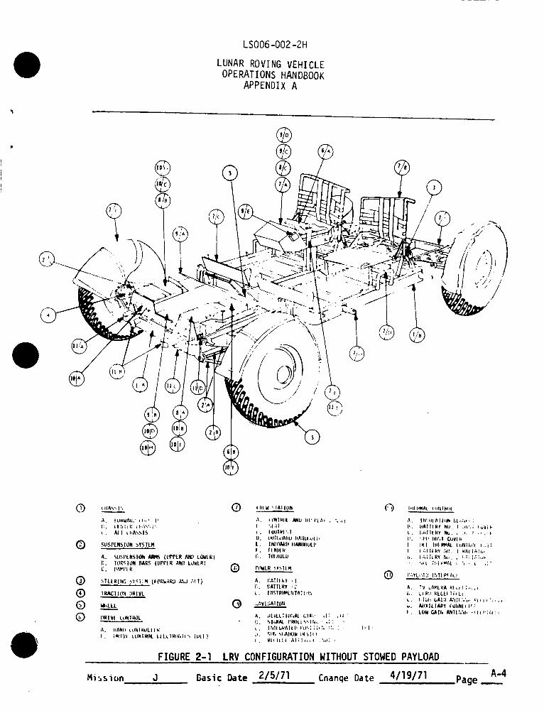
Lunar Roving Vehicle, details and locations of major vehicle subsystems, andimportant dimensions of the vehicle elements. Figure 2-I describes the basicLRV configuration and identifies and locates the principal LRV subsystems.Stowed payload is not shown installed on the vehicle but payload mountin!_interfaces are identified. Important LRV overall di_nsions are shown onFigure 2-2.
2.1 CHASSIS CONFIGURATION
The configuration details and principal dimensions of the LRV chassis areshown on Figure 2-3. The floor panels are shown removed to provide detallson the primary and secondary structural members.
2.2 SUSPENSION SYSTEM CONFIGURATION
Major components of the LRV Suspension System are shown and identified onFigure 2-4. The torsion bars serve to unfold the wheels during the deploymentoperations and to provide both contour following and chassis resiliency duringoperation on the lurain.
2.3 STEERING SYSTEM CONFIGURATION
Major components of the LRV Steering System are shown and identified onFigure 2-5. Only one decoupling ring is provided for each steering system,fore and aft. The aft decoupling ring is located on the right side of the
vehicle; the front decoupling ring is located on the left side of the vehicle.
2.4 TRACTION DRIVE CONFIGURATION
Internal configuration of the LRV Traction Drive is shown on Figure 2-6.
2.5 LRV WHEEL CONFIGURATION
The LRV Wheel construction details and critical dimensions are shown on Figure
2-7. The decoupling devices are actuated to provide free-wheeling capabilityin the event of drive seizure. Wheel deflection characteristics are shown in
Figure 2-8.
2.6 LRV CREW STATION CONFIGURATION
The major components comprising the LRV Crew Station are identified and loca-ted on Figure2-1OA. The layout and dimensional characteristics of the controland display console portion of the Crew Station are shown on Figure2-1OB.
MissionJ Basic Date 2/5/71 Cnange Date 4/19/71 Puge _A-2

LSOO6-OO2-2HLUNARROVINGVEHICLEOPERATIONSHANDBOOK
APPENDIXA
2.7 LRVPOWERSYSTEMCONFIGURATION
Theconfiguration of the typical LRVBattery and Dust CoverAssemblyisdefined in Figure 2-11. Battery dimensionsare provided on this figure.
2.8 LRVNAVIGATIONSYSTEMCONFIGURATION
The componentscomprising the LRVNavigation Systemare identified and locatedon Figure 2-12. Control and Display Consolemounteditems included in theNavigation Systemare shownon Figure 2-10B.
2.9 LRVTHERMALCONTROLCONFIGURATION
Themajor componentsOf the LRVThermalControl Systemare identified andlocated on Figure 2-13. Thedust coversare raised to permit radiation ofheat from the spaceradiators.
2.10 LRVPAYLOADINTERFACES
ThePayloadInterfaces with the LRVare shownon Figures 2-14A, 2-14B, 2-14C,and2-14D. Portions of the interface connectorswhich are not part of thebasic LRVsystembut which are permanentlyinstalled on the LRVare identifiedon these figures.
Mission J Basic Date 2/5/71 Cnange Date4119/71
LSOO6-OO2-2H
LUNAR ROVING VEHICLEOPERATIONS HANDBOOK
APPENDIX A
@@
®
®
® ?®
@
/
(_ _ ItA",', I ',
•"_. | IIKWAI_; t tt, ' I "
I:. I'1 ;I li I_ L FA",', 1".
I. All t llA_IS
.gIISPLN$ TON _,YS TLM
A. SLISPLNSION _ (L_PLR Mr) LOWLR)
C. TOR_,I_._N BARS (UPPIR AND LOWLR) #.-%
(_ STLLRtNG _,'_,T q (FORW-_RL) ANd ;,tT)
(_) f RA_IT ION :)RIVL
0 _'LLL 0
I)RI VI t LINIROL
;L liANb _ '_IN ] k'UL I I I_
I;. iIRIVI tliN|l_ll |ILL1RII;,I_,', {lql)
FIGURE 2-I
I Ill W ', IAI I IIN
I ",1 AI
. I LNJIWI ',I
U. KqlI I_L_ARLP IINILi_L ;*
L. | NI:BARII IIANINIULI_
I , FINIAR
Ii,. T()I IIUL L_
PIIWLR _Y_ILM
A. I:ATTLkY : I
t_. [:ATILR¥ :2
_. I r|STRI_L_'dTA" I_;_
;, ,",Vl l;AT lull
A, dli_ttil(IT_At (,YI_,' ,l: ,,t,l"
I;. .%|I_AJ_ I'RIILL".',Ih,. ',;1
I. Vltilll ,%li],_l .tdp; .
[rI
@
lilt I_AI. [IINIklll
A. Iri',II[AlltlN I,I._,:,_i :
I_. ItAIIIRY NU. I ;,i,'.;_uVil"
L. IJdlII(Y N_, , ._," I., ..I.
I!. '.I'IIhU',l CUVIN
i. Tt(l IHiPI_AL (1)NIk_11 _,i;
f. I,_IIII_Y _(i, I WAIIIAI_,i.
_,. I.A;IiRY N_.." _(,'dii,_;ul-
VAYLV,'.b' I hTI pl A_ I
A. TV LAMLRA rl,ll ;,.il
I,. L_PLI RLLLr Ti4 LI
u. high bAI:4 AhiI;,:,,, _'l_i, :,,,t
b. AIIXlLIARY rUNNI_ I';
I . LUId r,_lh ANII:,_d, -tlII';AI:I
LRV CONFIGURATION WITHOUT STOWED PAYLOAD
Mission J Basic Date 2/5/71 Cnanqe Date 4/19/71 Page _A-4

LSOO6-002_2H
LUNAR ROVING VEHICLEOPERATIONS HANDBOOK
APPENDIX A
Z
0
i,i
CZ_
!
i,i
_9
Mlsslon J Gasic Date 2/5/71 Cnanqe Date 4/19/71

LSOO6-OO2-2H
LUNAR ROVING VEHICLEOPERATIONS HANDBOOK
APPENDIX A
t
c_
c_
_.1
!
i,i
Mission J Basic Date 2/5/71 Change Date 4/19/71 Puge A-6

LSOO6-OO2-2H
LUNAR ROVING VEHICLEOPERATIONS HANDBOOK
APPENDIX A
L_J
F--
>-
Z0
L_J(_-
Or}
r_
=.J
I,Jr_
l,
Mibsl0n Basic Date 2/5/71 Cnange Date4119171

LSOO6-OO2-2H
LUNAR ROVING VEHICLEOPERATIONS HANDBOOK
APPENDIX A
__. MOTOR
SECTOR l _ _FEEDBACK POT
1_ 'I L___-
,.______,_._1L "
\ ,_ I_, "__ r _-TIE ROD ARM
/ f _,_ _ ___ _\ CONNECTION
\ /
REAR STEERING
RING
DECOUPLINGRING
FIGURE 2-5 LRV STEERING SYSTEM
Mission J Basic Date 2/5/71 Cnange Date 4/19/71 i>_ge A-8

LSOO6-OO2-2H
LUNAR ROVING VEHICLE
OPERATIONS HANDBOOK
APPENDIX A
DECOUPLING MECI
CIRCULAR SPLINE
HARMONIC
WAVE GENERATOR
FLEXIBLE SPLINE
WHEEL
BRAKEAS
BEARING
__ ,,,,,..@'_--__ __.y]r
IVE MOTOR
l.
.I1
f
SUSPENSION SYSTEM
ATTACH FITTINGS
WHEEL HUB
FIGURE 2-6 LRV TRACTION DRIVE
A-9Mission J Basic Date 2/5/71 Change Date 4/19/71 ,P_ge

LSOO6-OO2-2H
LUNAR ROVING VEHICLEOPERATIONS HANDBOOK
APPENDIX A
VIEW A-A
--TREAD
r OUTER
WHEEL DECOUPLINGDEVICES
32.19 DIA.
INNERFRAME
(BUMP STOP)
TIRE OUTERFRAME
FIGURE 2-7 LRV WHEEL
Mission J Basic Date 2/5/71 Change Date 4/Ig/7l Puge __A'lO

LSOO6-OO2-2HLUNARI_OVINGVEHICLEOPERATIONSHANDBOOK
APPENDIXA
RADIALWHEELLOAD(LBS)
600
400
200
135
63
DESIGNLIMI' LOAD
Z
i--il"-
,.Jl.a.
ZH
Z mm
l ].75 2 3 3.25
RADIAL DEFLECTION(INCHES)
4 4.15
FIGURE 2-8 LRV WHEEL DEFLECTION VS LOAD
A-11

LSOO6-OO2-2H
LUNAR ROVING VEHICLEOPERATIONS HANDBOOK
APPENDIX A
y __,._ PITC,H PIVOT
_" STEI_R
a .625 14" VERTICAL iooPOINT
iii '-- -- FORWARI__NEUIRA L
I"I \L_ -"=,=
FIGURE 2-9A LRV DRIVE CONTROL - HAND CONTROLLER
Mission J Basic Date 2/5/71 Change Date 4/19/71 7_ge A.__12

LSOO6-OO2-2H
LUNAR ROVING VEHICLEOPERATIONS HANDBOOK
APPENDIX A
k_
k_
r_W
0
Z0
W
e_
!
Z0
W
r_
e_
!
W
A-13X_,_s_un J Basic D_te 2/5/71 Cnanqe Date 4/19/71 _,,g_.

LSOO6-OO2-2H
LUNAR ROVING VEHICLEOPERATIONS HANDBOOK
APPENDIX A
DISPLAY AND CONTROL CONSOLE
EPLOYABLE
SECTION
FENDERS
(4 PL)
FOOTREST(2 PL)
ARM REST
BLSS ATTACHMENT STRAP
DEPLOYABLESECTION
VELCRO FOR PLSSLATERAL RESTRAINT
(2 PL)
SEATASSEMBLY
(2 PL)
PLSS VERTICAL
SUPPORT (2 PL)
OUTBOARD HANDHOLD
(2 PL)
INBOARD HANDHOLD(2 PL}
TOEHOLD ,(2 PL)
SEAT BELT (2PL)
FIGURE 2-10A LRV CREW STATION COMPONENTS
i_,g=. A-14,v,i:;_:r J l.:÷si_ n.,r. 2/5/71 c_.n,. "l,_t,. 4/19/71

LSOO6-002-2FI
LUNAR ROVING VEHICLEOPERATIONSHANDBOOK
APPENDIX A
r '_ . -ICAUTION/WARMING LATCH--% • I J(DISCARDEDAFTERLRV f \ _. 6" • ;-_'_ 2" --_DEPLOYMENT)/'_,_1 1_ _. ._.] l
[ __-- -- --" -1 ALARM I
m//Atuu¢ AnuAI-n,vn--'ll l_4"(/If |/, ,', /, // // // _'T r-_--r /I // ¢'_ ,_IA,,_- ........ ;II - -t' It--_/'// • i- ,I, , - II I/ i/ /r- _(ALARM ]
' / / // / I O...I t...._ I I1 III _ '_ - J v, ,, // .,, ,, -7,-T:,-,-,7 ,,- ,,- ', ///'. . • POSITION)/ tr "_ "_-- " __ ',.', ,, ,i ,, ,, ,,it, - :-7[-
PLILL TO DAMP7 /ITI HEADING _----_'-"_ _ SP|IO NAY
l_°l ' ,,I-_ mmi- I@/ o.o ...,.
SUNSHADOWDEVICE-- / " I I ....(STOWED POSITION) / POWen J POWER / TEMPEekTURI MONITOII
/ t,. i ir W-Nil-if" _tl "l IIUICT • I_ttllt'tl" liOtOe • --/ UP _ I i zl _ z =ovomve.,a,° q, a L "1' •
INTEGRATEDJ - _"_._ J r ' '_" "'0 r ---
POSITION " J : , , _ -win- ,d_INDICATOR r _ J ' '-: _ ' ,-A. 1,._ _,._.
(IPl) l _"'I "! """ " .:_.. ',,,- --..,, j .4:. ,o. ,.,,,,_ .,,. .=o. ,,LK, n
_' """ ' _ "'" " I _D_''-''
(_ =c J ST,,.,.o o.,v..ow.. :_.,,,, .-..,..I
oo. ,.,-@ @-0 0 0 (B-_ @-0,
'=i "" • ,.,o m.,
FIGURE 2-9A LRV CREW STATION COMPONENTS - CONTROL AND DISPLAY CONSOLE
Mission J Basic Date 2/5/71 Cnanqe Date 4/19/71 ._.gu__A-15

LSOO6-002-2H
LUNAR ROVING VEHICLEOPERATIONS HANDBOOK
APPENDIX A
m..=
i
m
m
I0._"_I
SCREW
FIGURE 2-11 LRV BATTERY AND DUST COVER ASSEMBLY
Mission J Basic Date 2/5/71 Change Date 4/19/71 Puge mA-16

LSOO6-OO2-2H
LUNAR ROVING VEHICLEOPERATIONS HANDBOOK
APPENDIX A
SPEEDMETER
SUN -'--ISHADOWDEVICE
DIRECTIONAL--- 1
GYRO UNIT /
-ODOMETER
(ALL 4 WHEELSI
INTEGRATED
POSITIONINDICATOR
ATTITUDEINDICATOR
SIGNALPROCESSINGUNIT
FIGURE 2-12 LRV NAVIGATION COMPONENTS
Mission _R_;,.'c __,:t-_ 2/5/71 ,.-_an_.,_ nat_4/19/71 _,,g_ A...-I7

LSOO6-OO2-2HLUNARROVINGVEHICLEOPERATIONSIIANDBOOK
APPENDIXA
DRIVECONTROLELECTRONICSANDTHERMALCONTROLUNIT
SPACE RADIATOR
GYRO(DGU)
DUST COVER BATTERY NO. 1
INSULATION BLANKEI15 LAYERS OFALUMINIZED MYLARAND NYLON NETTINGWITH BETA CLOTHEXTERNAL SURFACES
GYRO THERMAL STRAP
BATTERY NO. 1
FUSIBLE MASS & THERMAL STRAP
SIGNAL PROCESSING UNIT
(SPU) (DUST COVER NOT SHOWN)
BATTERY NO, 2
DUST COVER,BATTERY NO. 2
FIGURE 2-13 LRV THERMAL CONTROL
Mission J Basic D_te 2/5/71 Cnanqe Date 4/19/71 _ogu A-I_

LSOO6-OO2-2H
LUNARROVINGVEHICLEOPERATIONSHANDBOOK
APPENDIXA
COLORTVCAMERA
HI GAIN"S" BANDANTENNA
/
CONNECTIONTO THE LOW-GAIN
ANTENNA -----.D_ \\•_OR_AR _ .jRECEPTACLE /
//
j /
•
(TYPICAL FOR HIGH GAIN /
ANTENNA AND TV CAMERA) _
FIGURE 2-14A PAYLOAD INTERFACE-LCRU, HIGH GAIN ANTENNA, TV CAMERA INTERFACES
M_slon J Basic Date 2/5/71 Change Date 4/19/7] ?_ge __A-19

LSOO6-002-2H
LUNAR ROVING VEHICLEOPERATIONS HANDBOOK
APPENDIX A
HIGH GAIN ANTENNAAND GCTA ADAPTERINSERT (REMAINS ONLRV AT ALL TIMES)
LCRU OR GCTA CONNECTOR(DISCONNECTED FROM DUMMYCONNECTOR/DUST CAP BEFORE INSTALLING LCRU)
DUMMYCONNECTOR/DUST CAP(REMOVED AND DISCARDEDBEFORE INSTALLING HIGIIGAIN ANTENNA OR GCTA)
LRV FWD CHASSIS
--_GCTA POWER CONNECTOR
DETAIL A(TYPICAL 2 P'LACES)
LRV AUXILIARY CONNECTOR/LCRU CABLE POWER CONNECTOR
CABLE TIE-DOWN STRAPS Y,.'_ (SEE DETAIL A)
!
LCRU CONNECTOR
LCRU/TVlLRVCABLE
FIGURE 2-14B PAYLOAD INTERFACE ° LCRU/TV/LRV CABLE STOWAGE
A-20Mission J Gasic D_te 2/5/71 Cnan_e Date 4/19f71 ',,ge

LSOO6-OO2-2H
LUNAR ROVING VEHICLE
OPERATIONS HANDBOOKAPPENDIX A
16 MM DATA ACQUISITIONCAMERA
LOWANTENNA
TO ROTATE AZIMUTH SETTING,GRASP HANDLE, PUSH DOWN
TO UNLOCK, TURN TO DESIREDSETTING AND RELEASE. STAFFLOCKS IN LAST POSITION.
LRV INBOARDHANDHOLD
PUSH BUTTON TO
RELEASE AND/ORREMOVE STAFFFROM HANDHOLD
)
FIGURE 2-14C PAYLOAD INTLRFACE - LOW GAIN ANTENNA AND16 MM DAC INTERFACE
Ml_slon Basic Date 2/5/71 Change Date 4/19/71 Puge A-21

LSOO6-OO2-2HLUNARROVINGVEHICLEOPERATIONSHANDBOOK
APPENDIXA
LLETSUPPORTPOST(STOWED.).
i
POST TIEDOWN TAB
R. H. ADAPTER
REAR CHASSIS
FIGURE 2-14D PAYLOAD INTERFACE - LRV REAR PAYLOAD PALLET ADAPTERS
Mission J Basic Date 2/5/71 Change Date 4/19/71 :_ge A-22

LSOO6-OO2-2HLUNAR ROVING VEHICLE
OPERATIONS HANDBOOKAPPEr_DIX A
3.0 CONSTRAINTS AND OPERATIONAL LIMITATIONS
The LRV must be operated in such a manner as not to exceed the constraints and oper-ational limitations of the following subsystems:
3.1 CHASSIS SUBSYSTEM CONSTRAINTS
The constraints which apply to the chassis are concerned with loads imparted to thevarious chassis members. In order to control these loads, limitations are imposed
on location of stowed payload items. To preserve the factor of safety of 1.5 theLRV shall be loaded such that the loads in the chassis payload zones do not exceedthe maximum loads shown in Table 3-I. Overloading the vehicle beyond the total970 Ib. limit will also result in performance degradation as shown in Section 5.
The chassis frame is constructed of thin wall aluminum rectangular tubes which are
scalloped in certain areas for weight saving. These thin wall areas are subjectto damage from high-impact loads beyond the designed-for conditions. Therefore,the chassis should not be subjected to such use as supporting rock samples forbreaking apart the rocks with geologic tools wherein the geologic tools could strikethe chassis.
3.2 SUSPENSION SUBSYSTEM CONSTRAINTS
The suspension system is designed for a factor of safety of 1.5 based on a maximumgross weight LRV of 1500 lb. with the C.G. of the gross weight falling such thatnot more than 55% of the total weight is supported by the front or rear wheels.The factor of safety will be reduced if the LRV is loaded in such a manner thatthese limits are exceeded.
Suspension system thermal constraints are defined in paragraph 3.10.
3.3 MOBILITY SUBSYSTEM CONSTRAINTS
The only constraints concerned with the wheels, traction drives, steering and hand
controller are limitations caused by component capability discussed in Section 4
and by thermal limitations discussed in paragraph 3.10.
3.4 ELECTRICAL POWER SUBSYSTEM CONSTRAINTS
3.4.1 Batteries
The power subsystem is designed to use both batteries simultaneously on an approxi-
mate-equal load basis, i.e. one front and one rear traction drive should be operatedfrom one battery and the other front and other rear traction drives operated from the
other battery. Likewise the front steering motor should be operated from one
battery and the rear steering motor from the other battery. Only in a contingency
mode should all loads be transferred to one battery, since battery heat rise increases
with increase in battery current. This consideration is discussed in 4.2.
Mission J Basic Date 215/71 Change Date 4/19/711 • P_ge __A-23

LSOO6-OO2-2HLUNAR ROVING VEHICLE
OPERATIONS HANDBOOKAPPENDIX A
_J
0r-q
z
C)-J
,,i._J0o
C_..J-J
..J
t--OF-
0
0
L.)O.-J
wz0N
mm O0 mr_ 0[3 oO.-J -J _ ..J ..J ..J
0 0 0 (_ 0 0
r-- _:r
F--
L_J c_
u_ F--
-r(..) r,- r_
UJ UJ
F--
Z Z
r_
(,}J _ --J
Z _ :_tJJ L_ ._t_J m,m
_J L_J 0aO O0 0
..Jl ! m,
mm=_ "T- )-- mm
L_J I--- L_J m,m_m'r _--_-- )--_--_t._ ZtZ. Z
F--r_
OK t/)
_-- 0r-_ P.- m_- -r
4,,II I-....
--J
O0I..- e_
_Oe,¢_ I,.i_
-r _J 0
m,- o4_J X (_
..J"00
o0 F-- -rr_
F-Z
m-- Z "_"
r__(JJ
'"E)OCF-UC#I
(__,_Z,,m,.._mmr-_ h_
...J
._-_X_--_
_Z° I-.- uJ
Z0i-...iI---
I.--
:IE
-J
0.-J
e_..-1
_7
_J
I--
w
0N
C_,=E0_.J),-_JE
O0 U r-_ _j __
O=._J
..J
F-0
Missi0n Basic Date 2/5/71 Cnange Date 4/19/71A-24
P-,ge

LSOO6-OO2-2HLUNAR ROVING VEHICLE
OPERATIONS HANDBOOKAPPENDIX A
3.0 Continued
3.4.2 Switches and Circuit Breakers
To provide maximum crew safety ir event of undetected failure of drive logiccomponents, the following restrictions should be adhered to in sequentialselection of switch positions:
a. The two STEERING and four DRIVE POWER switches should be in the OFF position whenchanging position of the +I5VDC switch.
b. The +I5VDC PRIM or +15¥DC SEC circuit breaker should be closed and the + 15VDC
switc-h in PRIM or SE-C position, respectively, before operating the two STEERINGand four DRIVE POWER switches.
Proper order for selection of all circuit breakers and switches is given in Section2 of the basic LRV Operations Handbook.
3.5 NAVIGATION SUBSYSTEM CONSTRAINTS
a. The GYRO TORQUING switch is not to be kept in the LEFT or RIGHT position formore than two minutes. Aftertwo minutes on, the switch must be kept OFF fora minimum of five minutesto prevent damage to the torquing motor.
b. The navigation subsystem input voltage must not be allowed to be less than30 VDC to prevent excessive computation and display errors and to preventdamage to navigation equipment if the under-voltage situation is prolonged.If the VOLTS indicator indicates less than 60 the NAV POWER circuit breaker
should be opened. The VOLTS indicator should be checked periodically (at leasteach 15 minutes) to verify readings of not less than 60.
NOTE
Navigation readings should be reported and recorded by MCC beforeclosing the NAV POWER circuit breaker. Reapplication of powerwill cause loss of display retention.
c. NAV POWER should be on for at least 3 minutes before driving the LRV to allow
the directional gyro to reach operating spin speed.
d. The LRV must be level within + 6 ° in pitch and roll and parked downsun within+ 3 ° during navigation initiaTization and update to achieve required systemaccuracy.
3.6 DISPLAY AND CONTROLS SUBSYSTEM CONSTRAINTS
Crew procedures for operating the displays and controls are contained in the basicLRV Operations Handbook.
No constraints exist other than those already listed in 3.4 and 3.5.
A-25
Mission J Basic Date 2/5/71 Cnange Date 4/19/71 P_ge

LSOO6-OO2-2HLUNAR ROVING VEHICLEOPERATIONSHANDBOOK
APPENDIX A
3.7 CREWSTATION SUBSYSTEMCONSTRAINTS
No constraints to crew station operation exist when operated in accordance withthe crew procedures in Section 2 of the basic LRV Operations Handbook.
These procedures are based on the crew station structural capability. To main-tain the safety factor of 1.5 the loads imposed on crew station components shouldnot exceed the values shown in Figures 3-I and 3-2.
3.8 VEHICLE DYNAMIC OPERATIONCONSTRAINTS
The LRV is designed with inherent stability characteristics of wide wheel track andlow center of gravity. Static stability limits are shown in Figure 3-4. Overturnof the vehicle is a remote possibility, occurring only under severe conditions ofextremely tight turns at high speeds on steep slopes or collision with immovableobjects. Speeds, slopes, turning radii limits, and obstacle height to preventoverturn and sliding are shown in Figures 3-5 through 3-9. These curves are basedon the C.G. of the loaded vehicle falling within the envelope shown on Figure 3-3.The required increase in turning radius for preventing overturn caused by locatingthe loaded LRV C.G. outside the Figure 3-3 envelope is shown in Figures 3-1Othrough 3-15. Maximum allowable speeds to prevent exceeding structural designloads are shown in Table 3-111. The safe driving corridor for driving with onesteering assembly failed is shown in Figure 3-16.
3.9 PARKING CONSTRAINTS
3.9.1 During-Traverse Parking
There are no orientation constraints imposed on parking in sunlightduring traverses. The LRV must not be parked in shadow for longerthan 2 hours to prevent display and control console electronics damage.
Switch and circuit breaker positions for short-term parking are given in the basicLRV Operations Handbook.
3.9.2 Between-Traverses Parking
To prevent thermal damage to the control and display console instruments and tobe compatible with LCRU thermal requirements the LRV must be parked in sunlightoriented relative to the sun azimuth in accordance with Figure 3-17 when parkingthe LRV between sorties.
3.10 THERMAL CONSTRAINTS
The LRV is designed for operation in the lunar day at sun elevation angles ofgreater than Five degrees. All qualification tests have been conducted to thelunar environment temperature levels expected to be encountered by the LRV.Operations on the moon should be restricted to maintain components within thesetemperature limits. Temperature limits for specific components are defined inTable 3-11.
Mission J Basic Date 2/5/71 Cnange Date4119171 A-26
?_ge

LSOO6-OO2-2H
LUNAR ROVING VEHICLEOPERATIONS HANDBOOK
APPENDIX A
I00 Ib
HANDHOLD
J I00 IbTOEHOLDI00 Ib
OUTBOARDHAND HOLD
3
ALL LOADS ARE LIMIT LOADS
IH_BLSARDHAND- _ XM RES/__T HAND CONT!O_iiiii_i_S2io01_ b
FIGURE 3-I CREW STATION LIMIT LOADS (HANDHOLDS AND TOEHOLDS)
J Basic Date 2/5/71 Cnange Date 4/19/71 :>_gc _A-27Misslon

LSOO6-OO2-2HLUNAR ROVING VEHICLEOPERATIONSHANDBOOK
APPENDIX A
HI2-HI2
HI2-HI2
(_ J/2
J12
"L '
E*
I B
I
E _
ZSEAT BELT
+F
D*
-F
D*
L AND K DO NOT ACT
ON BOTH SIDES OFSEAT SIMULTANEOUSLY
* DISTRIBUTED LOADSACTING OVER THEAPPLICABLE AREA
TENSION LOAD - 160 LBS
LOADCONDITION A
1 27
II
3** 142
B C D E F G H J K L
51 326 175 92 70 23 17 9 113 113
2l 254 70 43 198 17 0 0 0 0
0 0 0 200 200 142 50 0 0 0
ALL LOADS ARE LIMIT LOADS
*_ CONDITION 3 LOADS DO NOT ACT SIMULTANEOUSLY
FIGURE 3-2 CREW STATION LIMIT LOADS (SEATS AND FOOTRESTS)
Missi0n J Basic Date 2/5/71
A-28Cnanqe Date 4/19/71 2_ge o

LSOO6-OO2-2H
LUNAR ROVING VEHICLEOPERATIONS HANDBOOK
APPENDIX A
c
o
STA
_ _TA12225
IiL STASTA Z = 86.25
_. STA STA X : 76.0Y-+3.2 X = 67.0
Y=-3.2
FIGURE 3-3 GROSS WEIGHT ALLOWABLE C.G. ENVELOPE
A-29Mission J Basic Date 2/5/71 Cnange Date 4/19/71 P_ge

LSOO6-OO2-2H
LUNAR ROVING VEHICLEOPERATIONS HANDBOOK
APPENDIX A
3.1.0 Continued
Maximum Survival Minimum MinimumOperating Upper Operating SurvivalTemperature Temperature Temperature TemperatureLimit Limit Limit Limit
Component °F °F oF oF
*Batterv 125 140 40 -15
DCE 159 180 0 -20
*Traction Drive 400 450 -25 -50
Wheel 250 250 -200 -250
SPU 130 185 30 -65
DGU 160 200 -65 -80
IPI 185 185 -22 -65
Suspension Damper 400 450 -65 -70
Steering Motor 360 400 -25 -50
*Analog Display on LRV Panel
TABLE 3-11 COMPONENT TEMPERATURE LIMITS
3.10.! Shadow Constraints
The LRV must not be operated in shadows for !onoer than 30 continuous minutes to
prevent damage to the wire wheels. The LRV must be exposed to i0 minutes of
sunliaht before re-entering shadow to allow adequate surface-to-wheel heat transfer.
The LRV must not be par$:ed in lunar shadow for longer than two hours to prevent
low temperature damage to the electronics in the control and display console.
A-30Mission J Basic Date 2/5/71 Cnange Date 4/19/71 _uge .---Hi i

LSOO6-OO2-2H
LUNAR ROVING VEHICLEOPERATIONS HANDBOOK
APPENDIX A
I0
a
I
I
I
i!'I
I
' _ \I <-
.J _ I
x I,-
I O,u <I z_ J \I oLo
', :i \, \'1"J I I I I
o
¢_
U
u
*f*
0
($:1:lU03(3)il'lONV:ldO'lS
J Basic Dote 2/5/71 Cnange Date 4/19/71 P,,ge_A-31Misslon

LSOO6-OO2-ZH
LUNAR ROVING VEHICLEOPERATIOn,S HANDBOOK
APPEt_DIXA
us.J
z.,[tUG.o-I
1- I--sl) *_o o_1 .J>- >-_._ s3nrIAJ uJz zuJ ud
II
ILtdr_
• Qo
\\\\\\
\ \\ \\\\\
\\\
\ \\ \\\
\ \\ \\ \
\ \
\\\\\\\
(iiH/W_i) _.i.l_)O'1|A _I'I_)IH|A
_is$1onBasic Date 2/5/71 Cnange Date
4119171A-32
,.,Puge o

LSOO6-OO2-2H
LUNAR ROVING VEHICLE
OPERATIONS HANDBOOKAPPENDIX A
w.J
Z
wL0,J
weL0.J
Z
0a
Z
Z
I-
I) • @
I I I I I
IN f_4 _" F-
-
Q
0
IJ.I.J
Z
U.I
C)..I
r_2:
4#)
z u
•-.." LL. i.- _D.,, o _" "_ zUU
zw _- _o u-Z U-UR
_-i,v
.JU.i
m
m
-I
0Z
_a.J
,.I
(tlH/Y()I) AII:_OliA/llNrl ONl(]ri$ |'I:)IHiA
Mission J Basic Date 2/5/71 Change Date 4/19/71 P-ge A-33

LSOO6-OO2-2H
LUNAR ROVING VEHICLEOPERATIONS HANDBOOK
APPENDIX A
W.J
z
uJG,.0
%• %0
|a
z_zn_:)I,-
(IIH/W)I) AII::X)'IDA IIWI'I 9NlOl'IS ]I'I_IIH|A
LLI
!<,+
Mission J Basic D_te 2/5/71 Change Date4/19/71 ....')uge...A'34

LSOO6-OO2-2H
LUNAR ROVING VEHICLEOPERATIONS HANDBOOK
APPENDIX A
uJ.J
z
&UG,.0..J
o o0 0
o0eq
UdG.c),./
z3_0t_
z2[nr
I-.
I I ,I I I
(tlH/W)I) A£1:)O13A II::)IHtA
-(
Z
_. I--
:} _JI-- 111
m:1[I/
ZIz
c_ _"
M-
111
C)
.J
0
,v_ission d Basic Dote 2/5/71 Cnange Date 4/19/71 )uge A-35

L_,{)O6-.OO2-2HLUNAR ROVING VEHICLE
OPERATIONS HANDBOOKAPPENDIX A
(_I
&__
Mission J Basic Date 2/5/71 Change Date411g/71 A-36
?uge --
LSOO6-OO2-ZH
LUNAR ROVING VEHICLEOPERATIONS HANDBOOK
APPENDIX A
I I I J I
($3H::)NI)
NOI.LISOd "IYWUOH OJ. ]AI,LY"I|I NOIJ.V_DO"I "D'_ "lY_lt,l.Y"l
o
Q.
Z
ZQ_
t'-
Mission J Basic Date 2/5/71 Change Date 4/19/71 i_,.geA-37

LSOO6-OO2-ZHLUNARROVINGVEHICLEOPERATIONSHANDBOOK
APPENDIXA
:E :E :E
w-- p
i I I i I
0WD
F-
a.
o
O_UJ
0_U.
w
r_o
(.DZ
ZOc:
I--
o
W
L._
(S3H3NI)NOIJ.ISOd"IVPIWOHO.L |AIJ.V'IIU NOIJ.V:)01 "9 "3 1Vl:lLV'l
Mission J Basic Date 2/5/71 Cnange Date 4/19/71 .,PugeA-38__.

LSOO6-OO2-2H
LUNAR ROVING VEHICLE
OPERATIONS HANDBOOKAPPENDIX A
:I
I I I ,J l
(SJH:)NI)
NOI.LISOd "IYWIION OJ. :ll^lJ.V"lg_l NOIJ.¥:X)I "0":3 "lV_lg.i.V'l
Mission J Basic Date 2/5/71 Change Date 4/19/71 Ouge A-39

LSOO6-OO2-2H
LUNAR ROVING VEHICLEOPERATIONS HANDBOOK
APPENDIX A
m
2
u
I I I I I
+, +,+<+
i+++-++
+ -P_.+I
..,+,,'-r0,.
EZ 0
o -- 0.',-' Z
I,-
0
0
(S|H3NI)NOIJ.Y::)0"I"lVVtUONO.L |^lJ.V'l|li NOIJ.V:30"I"_ ":31V::)l.l.lilA
Mission J Basic Date 2/5/71 Cnange Date 4/19/71 Puge A-40

LSOO6-OO2-2H
LUNAR ROVING VEHICLE
OPERATIONS HANDBOOK
APPENDIX A
L i I I i0
r-.
w Z
.o. v -
Z ry.
i-°Z
I--
($|H:)NI)
NOI IV:)O'I "IY1NIlONO.L 3^IJ.V"I|U NOIIY_)3 "_)':) "IY_)I.L_I:JA
Mission J Basic Date 2/5/71 Cnange Date 4/19/71 P_ge A-41

LSOO6-OOZ-ZHLUNARROVINGVEHICLEOPERATIONSHANDBOOK
APPENDIXA
w E
UJ0 nZ 0
I,- o
w'_ z
a " Z
-- Z _,-
ul W _
N_u.
I,- 0 LUUJ he.he. a,.
O
o IX
Z
Z
I I I I I o
($_iH3NI)
N011¥::)0"1 "1YllIION 01 :IAIIV'I|il N011¥30"1 "0"3 '1¥31111'aA
Mission J Basic Date 2/5/71 Cnange Date 4/19/71 Puge A-42...

LSOO6-OO2-2HLUNAR ROVING VEHICLE
OPERATIONS HANDBOOKAPPENDIX A
I
2r-
: \
• j I I
Ow
'<0
.4(ZLr0 0
z_.
UJUJ-- SjLj _1
I-- )'*
u- "_o_-
01--
,-,_..l,IJ I,./ij.'_
j 2/5/71 Change Date 4/19/71 7,,ge A_43,v_lssion Basic Date

LSOO6-OO2-2HLUNAR ROVING VEHICLEOPERATIONS HANDBOOK
APPENDIX A
MAXIMUM SPEED FOR DESIGN LIMIT LOADS WITH FATIGUE CONSIDERATIONS*
LURAIN TYPE IMIDRANGE) MAX ALLOWABLE SPEED
SMOOTH MARE 13 KM/HR
ROUGHMARE 8.5 KM/HR
HUMMOCKY UPLAND 8 KM/HR
ROUGH UPLAND 7 KM/HR
*BASED ON CEI REFERENCE MISSION
TABLE 3-1II SPEED RESTRICTIONS
Page A-44
MissionBasic Date 2/5/71 Change Date 4/19/71

LSOO6-OO2-2HLUNAR ROVING VEHICLE
OPERATIONS HANDBOOK
APPENDIX A
FOR SUN ELEV.ANGLES GREATERTHAN 2o
LRV
SOLAR
VECTOR
II0 °
120°
180 °
FOR SUN ELEV.ANGLES 5° - 12°
SHADED AREAS INDICATE THE PARKING ATTITUDES ACCEPTABLETO THE LRV AND TO THE PAYLOAD.
FIGURE 3-17 PARKING ORIENTATION CONSTRAINTS
Hibsion J Basic Date 2/5/71 Cnange Date 4/19/71 ,T>_ge A-45

LSOO6-OO2-2H
LUNAR ROVING VEHICLEOPERATIONS HANDBOOK
APPENDIX A
4.0 SUBSYSTEM PERFORMANCE DATA
This section defines the performance characteristics of the various LRV sub-
systems. Thermal performance characteristics are included for those subsystemshaving thermal limitations.
4.1 MOBILITY SUBSYSTEM PERFORMANCE
LRV power consumption per kilometer of travel as functions of speed, lurainslope and soil type is defined in Figures 4-I, 4-2, and 4-3. A constant speedwas considered in the preparation of these curves. The effect of vehicle accel-eration through the irdicated velocity was not evaluated but the curves do in-clude wheel slippage effects. Power consumption shown on these curves is basedon traction drive characteristics shown in Figure 4-4.
Battery current provided to the traction drives as a function of speed and handcontroller throttle position is defined on Figure 4-5.
The rate of traction drive temperature increase as a function of solar elevation
angle and drive temperature is defined on Figures 4-6. A zero degree slope wasconsidered in the preparation of these curves.
The effects of zenith angle and traction drive temperature upon the wheeltemperature increase for a solar elevation angle of 60° are shown in Figures4-7 through 4-I0.
The rate of traction drive temperature increase as a function of vehicle speedand traction drive temperature under zero degree slope and 60 degree solarangle conditions is shown in Figures 4-7 through 4-I0.
The rate of traction drive temperature increase as a function of vehicle speedand traction drive temperature under zero degree slope and 60 degree solarangle conditions is shown in Figure 4-11.
The rate of traction drive temperature increase for a solar angle of 60° andas a function of lurain slope and drive temperature is defined in Figure 4-12.
Mission J Basic Date 2/5/71 Cnange Date 4/19/71 , Puge mA-46

LSOO6-OO2-2H
LUNAR ROVING VEHICLE
OPERATIONS HANDBOOK
)
|
L_
"_V pla¢Z
it_
i
9.J
Ii
t | i I
Id (W)i/_IH-dWY) :11¥U NOIldWI'ISNO_)maMOd Iqt.LSA$ ]iAiWQ NOII3YII.[
I I I I i , I
_r
_d ()W)I/'_IH-d_Flf) 31¥_1 NOIld_flIN03 U|_Od AW'I 3¥10£
L_
..J
0
i
r_L_W
(,'3
V3
W OC
..¢ ZU (Z)
Zmum (_.
0
OC:
0
wr-,,"
Mission J Basic Date 2/5/71 Change Date 4/19/7l Page A-47

LSOO6-OO2-ZHLUNAR ROVING VEHICLE
OPERATIONS HANDBOOKAPPENDIX A
v)
Z
OX p
:I
|gE
.Z_ 8
L L
.J£" .a
<
X 0 XO. Il
or}
(.}
o
Id (WW/_H-d_¥) ]IYU NOIkdffNSN03
_ilOd HiISA$ i^llG NOII3Y_I
•Ld (WW/tIH-dffY) ii,LVtl I,K)lJ, dffNSN03 tl;l_Od ^3"1 "IVJ.OJ,
Mission J Basic Date 2/5/71 Change Date 4/19/71 Page A-48

LSOO6-OO2-2HLUNARROVINGVEHICLEOPERATIONSHANDBOOK
APPENDIXA
_z .0. __'_ ¥_1_ IIII
l f_iiiX _
2
• i I ,, I , ,j
a_o,_J
co (,c)
oop-
p-,
.JW
Z,=J 0
-- I--Z c_.
0
0
4
,-,+,
i-4
'd (WW/_IW-dtW) IIVBHOIldWfl$NO_ liMOd WilSA$1^I_IQ HOII_VU 1
O
I I , I I _)
ld (WW/HH-dWY) iL¥1 NOIldWflSHO_ li_Od ^U3 _¥101
Mission J Basic Date 2/5/71 Change Date 4/19/71 Page A-49

LSOO6-OO2-2H
LUNAR ROVING VEHICLE
OPERATIONS HANDBOOKAPPENDIX A
(%) _DN_IDI_
0[,.
I
0_D
I
I
0
i
0 0r_
I
0 C)i--t
0 0 0 0 0 0¢N 0 O0 _ _1_ ¢Nr-4 ,_
NdH - (]-_.qcIS ,T.CId_/IO
0
0
0O0
0
0_)
0i.r)
0n-i
o
0,.M
0
O0
0
0
0
E._Z0Q}
I
Z0
0_ 0
0
_ :>
,--1
!
¢y
I..1_
Mission J Basic Date 2/5/7] Change Date 4/19/71 Page A-50

LSOO6-OO2-2HLUNARROVINGVEHICLEOPERATIONSHANDBOOK
APPENDIXA
§
A-51
Mission J Basic Date 2/5/71 Change Date 4/19/71 Page

LSOO6-OO2-2HLUNAR ROVING VEHICLE
OPERATIONS HANDBOOKAPPENDIX A
I
a_0.J
L mL• •
I , II l •
>
* ii
O
I0
(NIW/do) DSY|W3NI |U(1,LVHIIdW|.I. dO |£VU
Mission J Basic Date 2/5/71 Change Date 4/19/71 Page A-52

LSOO6-OO2-2HLUNARROVINGVEHICLEOPERATIONSHANDBOOK
APPENDIXA
%
.J_3z
zo_
_u
_- Q. 4{u- 0 .J
l lo. o
f
w.'
I
t,- 0,-
t
Z i , ,,I
Q o o i
_NIW/de) |Syl_)ml ]_NLYU|dMBL dO iLVW
o
i.}7.
N
U,./..J
Z
2_U.JN
7.
U.JA,,"
OCUJ
UJ
LL.0
UJ
I
UJ
Z
o_i.-.
Ii
!
I.L.I
Page A-53Mission J Basic Date 2/5/71 Change Date 4/19/71

LSOO6-OO2-2HLUNARROVINGVEHICLEOPERATIONSHANDBOOK
APPENDIXA
z
J ).
N
o
Z
_r
Z
N
9.
_J
Z
"r
UJN
llg
Z
U.I
e_W
W
U.I
I
W
Z0
IX
I
U..
(WIM/de) iSVIIII:)NI IIIIN.I.VilIIdMt,I. dO IIJ.VU
Mission J Basic Date 2/5/71 Change Date 4/19/71 Page A-54

LSOO6-OO2-2HLUNARROVINGVEHICLEOPERATIONSHANDBOOK
APPENDIXA
w:
z
z
o
II II
/
(NIM., de) _iSV|ll:)N! ]illflIVltlidINili dO B.i.V_
uJ...t
'Z.c{
-rF-
'Zu.Jr*,,I
L_J
U.JGCU
U.J
I
N _I
r_
Z
Mission Basic Date 2/5/71 Change Date 4/19/71 Page A-55

LSOO6-OOZ-2HLUNARROVINGVEHICLEOPERATIONSHANDBOOK
APPENDIXA
hi li
"z
0
_t= _.
i
(NIM/de) ISV]ll3N| ]i_nLvtl]dV_]_. _0 ]_.Yti
t
,_
_JL_Z
2:
N
UJ
IIIp-UZ
UJ0.
U.Q
Ill
LUJ
Z
9U,4
0
"T
e_
Mission J Basic Date 2/5/71 Change Date 4/19/71 Page A-56

LSOO6-OO2-2HLUNARROVINGVEHICLEOPERATIONSHANDBOOK
APPENDIXA
.Jf,3z
I,,-
c_,_,
0 .I
0
i ,, L i i L io. . o._I' t_ eq ,-.
(NIW/d0) lSVtH_NI tUfliVUidWll dO J£VU
_0m
u'b
m
UJ
m
rv.Ln
Z0m
I--U
n_I--
oo
Mission J Basic Date 2/5/71 Change Date 4/19/71 Page A___-57

LSOO6-OO2-2HLUNARROVINGVEHICLEOPERATIONSHANDBOOK
APPENDIXA
%
%%%%%
%
%
00W_
.J0Z
Z0
l-..J 4[w .I _.ILl ¢u litX ,u ..j
X iu
).- _ E
i i io o o.u', qr (v)
y,
II
III
II,I[,
oI
0
@R
(Hllq/do) ]SY]I_I_)NI |IIfI.LYU:IdW:I.L dO |.1.¥11
0
" 0
0p
!
I
sd_
o I
Did
li.0..Is_
LUO.0.J
4_
LLI
UJn,UZ
U.In..
I--
£I.i c,u_. ,---
U.lI-- ,.,
U.. --_0
i.....*U.I u_I--
I
UJ
o_i-
l--
Mission J Basic Date 2/5/71 Change Date 4/19/71 Page _A-58

LSOO6-OO2-2HLUNAR ROVING VEHICLEOPERATIONSHANDBOOK
APPENDIX A
4.2 ELECTRICAL SUBSYSTEMPERFORMANCE
The battery nominal voltage is 36 +5 VDC. Voltage for various current drainsbetween 0 and 62 amperes is shown T_ Figure 4-13. Voltage vs. state of chargeai a final discharge rate of 47 amperes is shown in Figure 4-14. The rate ofbattery temperature increase as a function of current flow and battery tempera-ture is ,!efined on Figures 4-15 and 4-16. Separate curves are provided forboth left and right battery positions. The effect of battery temperature andsolar reflector dust coverage upon battery temperature change for both left andright batte_1 p_sitions is defined on Figures 4-17 and 4-18. Rates of batterytemperature increase with one battery providing all the required LRV power canbe obtained from Figures 4-15 and 4-16.
Distribution losses in the power distribution system are shown in Figure 4-19.The 36 volt losses (I_) are shown totaled for all four traction drive motorsusing the motor current scale. Motor controller cable losses (Im) are shownin Figures 4-19 using the total battery current scale.
A-59
Misslon J Basic Date 2/5/71 Change Date 4/19/71 ,,P_ge

c
Q.._I I
4_ 4.._ a_ X
q) u'D 0 r_
o,-- U_
-¢- 0 _
0 • _
r-- Q.) _I 4=) vI
LSOO6-OO2-2HLUiiARRNVI,!GVEHICLEOPERATi0;ISIIANDBOOK
A_PZND]X A
O
N
N
_Y
ZL_J
w
e_
L._
I'--ZL_
_')
I---._1
(-.,-)
L_
_.J
I--" ¢:_
0 "-.-"
',i_s_o_ J Basic Date 2/5/71 Change Date 4119/71 Page A-60

LSOO6-OO2-2HLUNARROVINGVEHICLEOPERATIONSHANDBOOK
_r_
of_
FIGURE
_F_°R_ _
I,-.,IUO£3
4-14 BATTERY VOLTAGE VS STATE OF CHARGE
°..:,.. L._
Q:
XU
N
0
I
o
.o
.o
Missien J Basic Date 2/5/71 Change Date 4/19/71 Page A-61

LSOO6-OO2-2H
LUNAR ROVING VEHICLE
OPERATIONS HANDBOOKAPPENDIX A
\
I
o
I
o8
A-62
Mission J Basic Date 2/5/71 Change Date 4/19/71 Page

LSOO6-OO2-2HLUNARROVINGVEHICLEOPERATIONSHANDBOOK
APPENDIXA
!0
0
\
I0
00
"tlWdo tSV]lU_)NI _ltlflJ.VtlidWi.L dO :lJ.Vtl
Mission J Basic Date 2/5/71 Change Date 4/19/71 _Page A-63

LSOO6-OO2-2HLUNAR ROVING VEHICLEOPERATIONS HANDBOOK
APPENDIX A
Z
w
0
m_&U
0
m_
w
:E
M-
)-e_
M-F-
mm
W
L.J
W
a-=E
J---
LL0
i
F"_L
.J
W(=C
Mission J Basic Date 2/5/71 Change Date 4/19/71 Page A-64

LSOO6-OO2-2HLUNAR ROVING VEHICLE
OPERATIONSHANDBOOKAPPENDIX A
ZuJ
0
U.;
0U
I-.
u./..y
l"-
e,..
l.u
>-
l."-&-
U
Z
i11
I,..-
a.
W
i1O
I
,,(
-r
IX
'T
(VK/de) ]lSVii3N! :aINiVlildW]lJ. dO ]liVtl
Mission Basic Date 2/5/71 Change Date 4/19/71__Page A-65

LSOO6-OO2-2HLUNAR ROVINGVEHICLEOPERATIONSHANDBOOK
APPENDIX A
"QO ",,0,,=-
II
ii
L_I
>-
C_i,i
IZ_")II,4
i,i -I
hi z
\\
\\
' %, S
"U_oa"os__ 1
\\\
i
ie-'- C_
I
i1I
tY
.o L_I
Z -'_
IX i _-- >.-
, i.=.
t _
Mission
0-,,I A
u_ l*-:If ,i_0 "I
Basic Date 2/5/71 Change Date 4/19/71
L_J
Of)0
ZQ
rY_
k-"
(3h
_T
L_J
i,

LSOO6-OO2-2H
LUNAR ROVING VEHICLEOPERATIONS HANDBOOK
APPENDIX A
4.3 NAVIGATION SUBSYSTEM PERFORMANCE
Directicnal Gyro Unit power consumption as a function of temperature is defined
on Figure 4-20.
Directional Gyro Unit drift rate as a function of temperature is shown in
Figure 4-21.
Bearing error as a function of gyro drift rate and navigation subsystem updateperiod is shown on Figure 4-22.
Sun Shadow Device Azimuth corrections as a function of vehicle roll angle and
sun elevation angle are defined on Figure 4-23.
Sun Shadow Device Azimuth corrections as a function of Sun Shadow Device
Reading and pitch angle for sun elevation angles of I0, 25 and 40 degrees areshown in Figures 4-24, 4-25, and 4-26.
A-67J Basic D_te 2/5/71 Cnange Date 4/19/71 i_uge
M_SION

LSOO6-OO2-2HLUNAR ROVING VEIIICLEOPERATIONS HANDBOOK
.......... • .... I
r--
I
.... t ....
: .... i11ii]i_ii• _ ........ t .... 4
•.. _........!TTTIq-IIi
.........: !!i:t!!:i...
: :i!ii li ifiiii!..-} -."
1:i[ I, t,t ''_I,, II II ,
_ i i ; | i i I I : _ I
..... I • I * I// ; I t 1...... L _, I1/ !,:i,_, , , _! i_ l_i_i
.... ;,. |;i.I1_ t..... i, _1i_1,11_
.... ;:, i,,;1_;t
..... _'- m''!t! t!!t
..... t_,' " t I !
:::: ilJ_ Iltl liti:::: !!!ii_!!!lii!:
i ii! t_:: ',t|7 i|:_i !__1__i r'2 ' :i!:: :/! : : :i
:::_::!il:il;;;!,, iii' , ,
, , _ .... l,i,|i,l_
.... t_.., _4: ,I, i,
!i!:l:i!i ii!!tii!!:.... I
.... :,,_,/lttili,::::i::!illtfi-lfl_;_
i .... i;,ii,.,.
• . ° _L--
:ii' * t "
t t t
1.1.-
1
t
LSOO6-OO2-2HLUNAR ROVING VEHICLEOP[ RAT!O_:S HAPiD',_,OOK
APPENDIX A
i .... ii ........... i
'I+Ik
.... t ....
.... i
' ' ' 1
.... L
_++ss:o,_ J Basic Date 2/5/71 Change Date 4/19/71 Page A-69

LSOO6-OO2-2HLUNAR ROVING VEHICLEOPERATIONS HANDBOOK
APPENDIX A
_D
(o_a) _lOaH '_Wl_fH|i q
.... -- ........ I. _L_ ............. _ ,
Basic Date 2/5/71 Change Date 4/19/71
O
%
p_
i,if_
I--
_C
!
i,i
D_.
Q
Mission J Page A-70

LS006-002-2_ILUNAR ROVING VEHICLEOPERATIONSHANDBOOK
APPENDIX A
I II. OBTAIh ROLL ANGLE FROM
ATT. IND.2. PROJECT ANGLE UP OR
DOWN TO SUN ANGLEINTERCEPT.
!
3. PROJECT TO SSD CORRECTION.
i I
LEFT
10
10o._-"_
15o--_j
2o°_,._
_oo../X35°s
- 40°4J_5o
50°C
////
ROLL ANGLE (L)
v
+15
SUN ANGLLS60 °
/
55o
50o
7/5 ° 40°
9//+_o /////.),O,_o°
10°
_""'-_-ROLL ANGLE (R) ___
_5¸
5 I0 15
--10
---15
ACTUAL VEH. HEAD. =
(SUN AZ -180°) - (SSD) +
(CORRECTION)
SSD = + (SHADOW TO RIGHT)
= - (SHADOW TO LEFT)
ROLL CORRECTION FOR SSD
FIGURE 4-23 SSD AZIMUTH CORRECTION FOR VEHICLE ROLL
X_iun J Basic _te 2/5/71 Cnange Date 4/19/71 O_ge A-71w

LSOO6-OO2-2HLUNAR ROVING VEHICLE
OPERATIONSHANDBOOKAPPENDIX A
SSD ANGLE (L)&
15
+20°
lO
IPITCH DOWN
PITCH UI
FIGURE 4-24.
CORRECTEDSSDANGLE FOR PITCH
r lSUN ELEVATION : I0°
I_ +20°
PITCH UP
+5
'+I0
,+15
PITCH DOWN
ISSD ANGLE (R)
lO
CORRECTED SSD ANGLE FOR VEHICLE PITCH (I0° SUN ELEVATION
Mission J Basic D_te 2/5/71 Cnange Date 4/19/71 i_ugeA-72

LS006-002-211LUNAR ROVING VEt(ICLLOPERATIONSHANDBOOK
APPENDIX A'
CORRECTED SSDANGLE FOR PITCH
SUN ELEVATION = 25°
I
-15 PITC_HUP I +20°
• ' j_/
SSDIoANGLE_/_(L)5/ +5 5
PITCH DOWN +I0
0° +20°
PITCH UP
O
.,o-5
SSD ANGLE (R)lO 15
+15
FIGURE 4-25 CORRECTED SSD ANGLE FOR VEHICLE PITCH (25° SUN ELEVATION)
Misslon J Basic Date 2/5/71 Change Date 4/Ig/71 i_ge A-73ii i |l

LSOO6-OO2-2HLUNAR ROVING VEHICLE
OPERATIONS HANDBOOKAPPENDIX A
CORRECTED SSD
ANGLE FOR PITCH
SSD ANGLE (L)
15
i
SUN ELEVATION = 40°
15
-lO"J
PITCH UP
PITCH UP
+20 °
-10 _ +lO°
-s , .R,
PITCH DOWN
5 lO
SSD
+lO
+15
,ANGLE (R)
15
FIGURE 4-26 CORRECTED SSD ANGLE FOR VEHICLE PITCH (40° SUN ELEVATION)
Misslon J Basic D_te 2/5/71 Change Date 4/19/71 ;;ugeA-74

LSOO6-OO2-2HLUNARROVINGVEHICLEOPERATIONSHANDBOOK
APPENDIXA
4.4 DISPLAYSANDCONTROLSSUBSYSTEMPERFORMANCE
Torquerequired to provide throttle control at various handcontroller angulardisplacementsis defined on Figure 4-27.
Torquerequired to effect steering control at various handcontroller angulardisplacementsis defined on Figure 4-28.
Handcontroller forces to accomplishvehicle braking as a function of handcontroller linear andangular displacementis defired on Figure 4-29.
M_sslon J Basic Date 2/5/71 Cnan_e Date .. 4/19/71 P,,ge A-75i

LSOO6-OO2-2HLUNAR ROVING VEHICLEOPERATIONS HANDBOOK
APPENDIX A
I DASH LINE INDICATES
I NOMINAL TORQUE VS
I DISPLACEMENT
TORQUE
(IN-LB) I' 16-
_'-'1 /--TORQUE LIMIT
---- 4-12 L__JE_ ...........UE BAND
FROM O°F TO 200°F
10"
1II
12 10 8 6 4
REVERSE
6 8 I0 12
FORWARDDISPLACEMENT (DEG)
FIGURE 1-12
I
I
TORQUE R£QUIRED TO ROTATE I!ANDCONTROLLER FOR IHROTTLE CONTROL
Mission J Basic Date 2/5/7] Change Date 4/19/71 Page A-76

LSOO6-OO2-2H
LUNAR ROVING VEHICLEOPERATIONS HANDBOOK
APPENDIX A
24
I
I!I
Ii
I
I
36
]2
28
24
i 2O16
12
nIGIIT
lO 0 6 4 2
| I 1
III
/
!
4
|
L2
16
20
24
28
32
36
s_F I14 ° * |5 o
•.-lo. ._ "Ill,7 _ ,j
1/t
i I
I
I I _1 II
.4.- II , !1!
'i I iI, i
4 4 O 10 12 14 15
DISPZ,ACImEWT (DIrG)
T.tr_
FIGURE 4-28 TORQUE REQUIRED TO ROTATE HAND CONTROLLER FOR STEERING CONTROL
Mission J Basic Date 2/5/71 Change Date 4/19/71 i)uge mA-77

LS_O-OO2-2hLUNAR ROVING VEHICLE
OPERATIONS HANDBOOKAPPENDIX A
4C
36
32
28
24
- 20,J
t_J
_-_I_,c_cC)LL
12
8
4
LIMIT STOP 4.0 o 4.3 INII
PARKING LATCH I
I FORCE 30 LB.
I II iI I I
I II II I I
i II I
I I I
I I I
I iI I II
I II i
I PARKING I
I LATCH II POSITION
2.6.- 3.1 IN I
I II I II I I
.B 1.2 l.6 2.0 2.4 2.8
DISPLACEMENT (IN.)
I I I ! I5 10 15 20 25
DEGREES (REF)
30
FIGURE 4-29 BRAKE CONTROL FURCE VS DISPLACEMENT
Mission a Basic Date 2/S/7] Change Date 4/19/71 Page A-78

LSOO6-OO2-2HLUNAR ROVING VEHICLE
OPERATIONS HANDBOOKAPPENDIX A
5.0 VEHICLE PERFORMANCE DATA
5.1 VEHICLE DYNAMIC RESPONSE
The LRV will exhibit dynamic characteristics dependent on the surface traversedand the speed at which the surface is traversed.
The vertical acceleration at the LRV seats for various speeds over varioussurface types is shown in Figure 5-I.
The vibration environments induced into the various LRV payload zones as aresult of traversing the lunar surface are shown in Table 5-I.
J 2/5/71 Change Date 4/19/71 ;uge __A-79_ission Basic D_te

LSOO6-OO2-2HLUNAR ROVING VEHICLEOPERATIONS HANDBOOK
APPENDIX A
t&lmt
:I :I
E !
0
i
F-
U0..JM4
0| I !
_ ew
0¢ X
..I Iw •U w
O.>-)-
Z
J
(:Z
>-
m
U0
U.0
X
o_p-UZ
c_--}cn
U ,--
u.oZ
o_
,(me
.J
U-(
)-m_&U
_l_SlOn _asic L)ate 2/5/71 Change Date _ 4/19/71A-80
)uge

LSOO6-OO2-2HLUNAR ROVING VEHICLE
OPERATIONSHANDBOOKAPPENDIX A
0
mr_
0
Z<
N N N"I- O'I -:" ..I._ l:_ -r- -I-.) t:_
4.J _ ,,,I-) ,.I-) _ L) 4J_U(J,{%.l O _ L,I('M O _ (JC,,J O L,r)
--J O _ O O.I (:3 C:_OJ O 13_e,J
t--- O_ID It O_.O II O_la II
.--I + O ,-- + O ,-- + O ,--Q;
N U N U N UI'-" N N "r c_E N N "T- <Z: N N -_'::Z:I, ::E -r" -1- -r" -T" -r-
C_ 0 ,_ ,'- CD _ f-- (_ ,_ ,'-'-0 ,'-- '--" ,'--
0 0 0 ,-- 0 00_ 0 0 0,--
_. 5. 5.Od L_)O _ (x.ILC)O (I; CXJI-") O (I)
c;_;_ • " " • _: " •o oo o _
N4-) N-I,J O') "r .l.a_
N (J O'_ 4J "I- U _ U•t-) ::E Or".. U_OkE) -l-)(',,J003
OC_J r_ _. l:_r_ O r_ .OYOO 43 "OO _Od "o O
"l_lrO _:) III (_1'_) II "t30LO II• I _ • I • I
O_ O ,'-- + O ,--- O',O
U N U N U N UN N-r'_ N N'T- _ N N -r (:E
I.-- --,'- -r -r-r -r" -r,"Y O(,/) O (..,") O(-_
IO0--_ _')0 _ I_')0 ._
O,--',-- C_ Or_',-- O,-- _'O_
i---o o o,-.- ooo_ ooo_.l-a ,._ .1-) _1 .t-_ .._ .I-) ¢_ ,.l,a, .l-a' .I-) i'_
CXlCC) O (I; CM t_')O _J _1430 (I;
O_O O O ,"- O OO_O
-J
_J
k
>
N 4 _-r N (J
4.) _._'_- O
O C_J ,"'(".3
_ I_ "_ I/')O1 IIO ,--" I
• O TM, • ,--
NN N N N"r ¢=E•"r -r -r -r
U_ _.O C) C) ._-.... C3et"
Or--" CJ i.r_ _--
0 0 0 0 0_-4.) ¢.) 4J _ _-J ro
Ou un _DCDCD _J• . . . . •
CD CD,--Od_CD
(/)Z
O (-0 _---_" I Zi--,O,..,_--;O
--r-_Z_--
,=:OZ
_r_O
i, ZO_O_
>c_-J
k--<
h-
ILl
ZU.I0(._)
_,-,_ I.,),.
Z I,._1
ZZ,-_0,--, C:_k--,_
_.J
_7
--J
<
_i_si0n J Basic Date 2/5/71 Cnange Date 4/19/71 ?uge __A-81
LSOO6-OO2-gHLUNAR ROVING VEHICLEOPERATIONSHANDBOOK
APPENDIX A
5.2 RANGE, SPEED, LURAIN CAPABILITY
5.2.1 Range
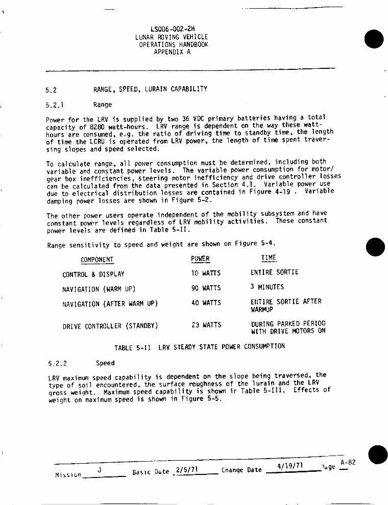
Power for the LRV is supplied by two 36 VDC primary batteries having a totalcapacity of 8280 watt-hours. LRV range is dependent on the way these watt-hours are consumed, e.g. the ratio of driving time to standby time, the lengthof time the LCRU is operated from LRV power, the length of time spent traver-sing slopes and speed selected.
To calculate range, all power consumption must be determined, including bothvariable and constant power levels. The variable power consumption for motor/gear box inefficiencies, steering motor inefficiency and drive controller lossescan be calculated from the data presented in Section 4.1. Variable power usedue to electrical distribution losses are contained in Figure 4-19 • Variabledamping power losses are shown in Figure 5-2.
The other power users operate independent of the mobility subsystem and haveconstant power levels regardless of LRV mobility activities. These constantpnwer levels are defined in Table 5-11.
Range sensitivity to speed and weight are shown on Figure 5-4.
COMPONENT POWER TIME
CONTROL & DISPLAY I0 WATTS ENTIRE SORTIE
NAVIGATION (WARM UP) 90 WATTS 3 MINUTES
NAVIGATION (AFTER WARM UP) 40 WATTS ENTIRE SORTIE AFTERWARMUP
DRIVE CONTROLLER (STANDBY) 23 WATTS DURING PARKED PERIODWITH DRIVE MOTORS ON
TABLE 5-11 LRV STEADY STATE POWER CONSUMPTION
5.2.2 Speed
LRV maximum speed capability is dependent on the slope being traversed, thetype of soil encountered, the surface roughness of the lurain and the LRV
gross weight. Maximum speed capability is shown ir Table 5-111. Effects ofweight on maximum speed is sho_ in Figure 5-5.
A-82Misslon J Basic Date 2/5/71 Cnange Date 4/19/71, Puge

LSOO6-OO2-2HLUNAR ROVING VEHICLEOPERATIONSHANDBOOK
APPENDIX A
SMOOTH MARE
ROUGHUPLANDS
SURFACEROUGHNESS
SLOPE MID-RANGE PSD
0 ° 9.5
5_ 8.2
I0° 7.3
0* 10.5
5° 8.7
10° 7.6TABLE 5-111 LRV SPEED CAPABILITY
5.2.3 Lurain Capability
The LRV is designed with the following capabilities of traversing the lunarsurface:
Crevasse Crossing Capability
Step Obstacle Climbing CapabilityClearance Under Chassis
70 cm width35 cm high35 cm
Slope climbing capability of the LRV is shown in Figure 5-6.
5.3 THERMALPERFORMANCE
Themal performance characteristics of the LRV are defined in Section 4 underthe appropriate subsystem performance paragraph,
5.4 CONTROLLABILITY
5.4.1 Steering
The LRV has a turning radius of 122 inches utilizing the four wheel steeringcapability. The steering rate is such that lock-to-lock steering angle changecan be accomplished in 6 seconds. Crewman forces required to control steer-ing by use of the hand controller are shown in Figure 4-28.
5.4.2 Braking
Stopping distances for various initial speeds and different slopes are shownin Figure 5-7.
Hand Controller forces required to effect braking are shown in Figure 4-29.
Mission J Basic Date 2/5/71 Cnange Date 4/19/71 i>_gejA-83

LSOO6-OO2-2HLUNARROVINGVEHICLEOPERATIONSHANDBOOK
APPENDIXA
5.4.3 Speed
At high speedsthe LRVcanbecomeuncontrollable. Thecontrollability speedlimit is basedon wheel slip angle considerations and tends to be independentof lurain type. Thecontrollability speed limit should be utilized for mission
planning purposes. Double Ackerman steering was used.
Actual driving experience on the moon's surface should dictate the final con-
trollability speed restrictions.
CONTROLLABILITY SPEED LIMIT
ALL LURAIN TYPES lO KM/HR
TABLE 5-1V LRV CONTROLLABILITY SPEED LIMITS
__I
A-84Mission J Basic Date 2/5/71 Change Date 4/19/71 Page ___-

LSO06 -002 -2tt
LUNAR ROVING VEHICLEOPLRATIONS IIANDBOOK
APPLNIJIX A
c. ,_1::x::Z
\
I
i! ......
i i
\\
\
. w--
..... #
Z
.J
n
ne
W
Z
_ee_
Z
I
v o'JL_
C3
tJ
\,11 _A
L_
W
lID
IJ--
_ C> _ 0
C_
Miss10n J Basic Date 2/5/71 Cnanqe Date 4119/71 ;_9e A-85o

LSOO6-OO2-2HLUNAR ROVING VEHICLE
OPERATIONS HANDBOOKAPPENDIX A
f_LL.
_r
=D=
,=J
0
F'-
rt_u.iI--LU
C_OZ..J
¢Y .....
0"r
U.In
W
0,-1
v
,_1
_.J
e_....1
0
w
f..l-
i,0
w
I
Mission Basic Date 2/5/71 Cnanqe Date 4/19/71A-86
P,,ge

LSOO6-OO2-2H
LUNAR ROVING VEHICLEOPERATIONS HANDBOOK
APPENDIX A
WEIGHT
LB
÷ DATA TO BE SUPPLIED BY MSFC
!- 0 +
RANGE
FIGURE 5-4 EFFECT OF WEIGHT CHANGE ON RANGE FOR FOURLURAIN TYPES
A-87Mission J Gasic D_te ,.2/5/71 Change Date 4/19/71 )>_ge

LSOO6-OO2-2HLUNAR ROVING VEHICLE
OPERATIONSHANDBOOKAPPENDIX A
A WEIGHTLB+
DATA TO BE SUPPLIED BY MSFC
MAX VELOCITY KPH +
FIGURE 5-5 EFFECT OF WEIGHT CHANGE ON MAXIMUM VELOCITY FORFOUR LURAIN TYPES
MissiOn Basic D_te 215171 Cnanqe Date 4/19/71A-Si_

LSOO6-OO2-2HLUNAR ROVING VEHICLE
OPERATIONS HANDBOOKAPPENDIX A
DATA TO BE PROVIDED BY MSFC
i ....
FIGURE 5-6
SLOPE CLIMBING CAPABILITY FOR VARYING C.G. LOCATION
M_sion J Basic D_te 2/5171 Cnanqe Date 4/19/71 ?uge hA-89

LSOO6-OO2-2H
LUNAR ROVING VEHICLEOPERATIONS HANDBOOK
APPENDIX A
_°
22
2O
STOPPING DISTANCE VERSUS INITIAL VELOCITY FOR VARIOUS SLOPES
/
//
/I
I
/
/
_20*
//
//
-10 o
0 o
10°
20o
r_
L_
r_
6 8
INITIAL VELOCITY (KmAr)
I I I10 12 14
!16
A-90Mission J Basic Date 2/5/71 Cnange Date 4/19/71 P_ge ---

,v,_-
0
0
- 0
0
,I I i I
0 -- 0 00 0
00
I._ _..I_(..)IJ.l _-
I I I I0 c-_ "". (:D 0 0
p.=.l
F,,%1_
k_.=dF-- (.,)
LS006-002-2tt
i.a.i:E:
I.aJ,.J
ZI.aJ::3C_"W,,.,,.i,
m,-,,:CWZ
,=,.I
-rz
--_--I0_-
I I I IC) 0C_
C_
I-'-:
I--0 l_J
I,L.I..-I
¢Y
-J
, _-,r'. -"_,o
Z
.-J0 ,I
0I I
00
%1_
i,=- (.._
0.
I0 00 0
00
0
0 Z
,..J
wz-r
C:,r'_
r',,-::)¢/}
0I__
I--
c_
_J
I---
LJ.J
C_
0
COI
r_
¢Z)
Ml_sion J Basic Date 215/71 Change Date 4/19/71 _ge __A-91

LSOO6-OO2-2H
LUNAR ROVING VEHICLEOPERATIONS HANDBOOK
APPENDIX A
WE IGHTDATA TO BE SUPPLIED BY MSFC
FIGURE 5-9 EFFECT OF WEIGHT CHANGE ON CONTROLLABILITY FOR
FOUR LURAIN TYPES
Mission Basic Date 2/5/71 Change Date 4/19/71A-92
Puge .._

LSOO6-OO2-2HLUNAR ROVING VEHICLEOPERATIONS HANDBOOK
APPENDIX A
6.0 SPECIFIC VEHICLE DATA
6.1 LRV-I
6.1.1 Constraints
No constraints other than those shown in Section 3 are applicable.
6.1.2 Subsystem Performance
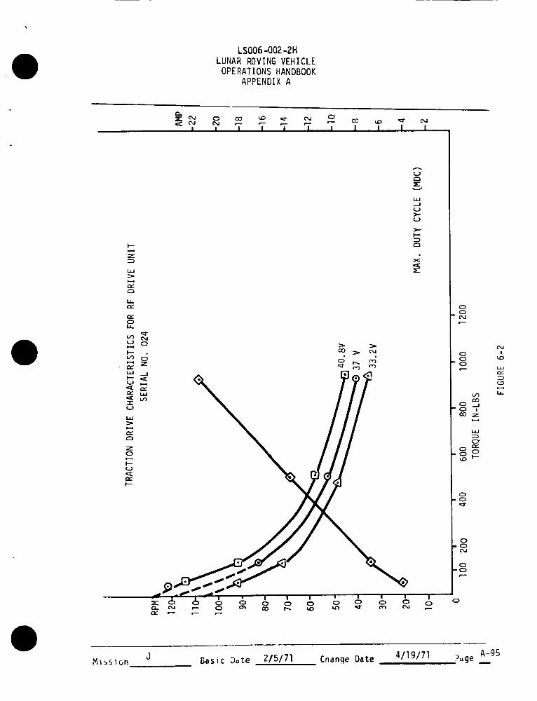
The traction drive characteristics for each of the four traction drives on
LRV-I are shown in Figure 6-I through 6-4.
Forward and rear steering motor maximum current measured during acceptance testwas 1.50 amps for the front and 1.45 amps for the rear against a torque of200 ir-lbs.
6.1.3 Vehicle Performance Data (Acceptance Test Data)
Power consumption characteristics of the navigation system are shown on Table6-I.
Chassis ground clearance under full load (1520 l_s.) is 35.1 cm.
6.1.4 Controllability (Acceptance Test Data)
TFe turning radius measured during acceptance test is 3.1 meters.
Lock-to-lock steering required 5.0 +_ _l seconds, against a torque of 200 in-lbs.
6.1.5 Weight and Center of Gravity
The weight and C.G. of LRV-I in all flight and deployed configurations is shownin Tables 6-11 and 6-111.
6.l.6 Navigation Odometer Factor
The LRV-I navigation system is set up such that the odometer will register 0.245
meters per count. Thc.-reare 9 counts per wheel revolution.
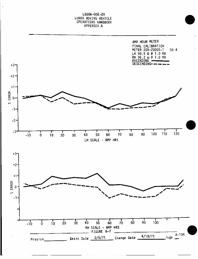
6.1.7 Meter Calibration
The final meter calibration curves for each of the four meters on LRV-I are
shown in Figures 6-5 through 6-8 .
Mission
_-93J Basic Date 2/5/71 Change Date 4/19/71 P-ge

LSOO6-OO2-2HLUNARROVINGVEHICLEOPERATIONSHANDBOOK
APPENDIXA
I ' T "i" _ 'T i i i I i
0
"T
I,.i-
0
Mission J Basic Date 2/5/71 Cnange Date 411gl71A-94
.....Puge ---
LSOO6-OO2-2HLUNARROVINGVEHICLEOPERATIONSHANDBOOK
APPENDIXA
eL_-- OU,:: eU
I
0 CO _C) _ ¢xJwm- _ _
I I I I I
0
l I I I
I--
LtJ
hPf
E)I,
V_ (M(J 0I-.-I
_--q ZPt"LLI .--I
"-r0
i,i
i--iE
0
U
EI--
O0 _ Oj
=E
i.i_J(J>-(J
I--
E_
X
00
" C%1P
000
oJ
lidPc"
I.L
0
0
M_slon J Basic Date 2/5/71 Cnange Date 4/19/71 Puge mA-95

LSOO6-OO2-2H
LUNAR ROVING VEHICLE
OPERATIONS HANDBOOK
APPENDIX A
! I
COe---
!
e,-- _ e--
! I ! I I I I I
00
A-96J Basic Date 2/5/71 Cnanqe Date 4/19/71 ?uge .--Mi_slon

LSOO6-OO2-2HLUNARROVINGVEHICLEOPERATIONSHANDBOOK
APPENDIXA
0-_ 0 CO _0 m_" o_ 0
I I I I I I 1
cO _C) _ c_
I I I
0
0
0
,v,ission J Basic Date 2/5/71 Cnanqe Date 4/19/71 :_,,geA-97

LSOO6-OOZ-2H
LUNAR ROVING VEHICLEOPERATIONS HANDBOOK
APPENDIX A
NAVIGATION SYSTEM RESET AND WARMUP
NSSCURRENT
(AMPS)
BATTERYVOLTAGE TO
SPU
(VOLTS)
NSSPOWER
CONSUMED
(WATTS)
2.36 34.8 82.1
LRV-I rlAVIGATIONSYSTEM POWER CONSUMPTION
TABLE 6-I
Mission J Basic Date 2/5/71 Cnange Date 4/19/71 Puge .._A-98

LSOO6-OO2-2HLUNAR ROVING VEHICLE
OPERATIONS HANDBOOKAPPENDIX A
I.iJZ
0
z
0
z
_A
--l-
e_-.,,1
_D
_J
I..-
Misslon J Basic Date 2/5/71 Change Date 4/19/71 ?.ge _A-99

LSOO6-OO2-2HLUNAR ROVING VEHICLEOPERATIONSHANDBOOK
APPENDIX A
LRV-I LOADED WEIGHT DISTRIBUTION: FRONTWHEELS 48.4%REAR WHEELS 51.6%
LRV-] LOADED WHEEL LOADING: RIGHT FRONTLEFT FRONTRIGHT REARLEFT REAR
365.5 LBS (24.0%)369.9 LBS (24,3%)390.2 LBS (25,7%)394.8 LBS (26.0%)
TABLE 6-III LRV-I LUNAR OPERATIONAL WEIGHTDISTRIBUTION - STATIC, LEVELLURAIN CONDITION
A-IO0Mission J Basic Date 2/5/71 Change Date 4/19/71 7uge
LSOO6-OO2-2HLUNAR ROVING VEHICLE
OPERATIONSHANDBOOKAPPENDIX A
l,i
c_c_
r,,
r_U.II--W
..._.1
0
"3"
-.I
i,0
"7
F-..
Mission J Basic L)_te 2/5/71 Cnange Date 4/19/71 ?uge _A-IOI

LSOO6-OO2-2HLUNARROVINGVEHICLEOPERATIONSHANDBOOK
APPENDIXA
0:C
w
+3-
+2-
+l-
+ ERROR: METER READS LOW- ERROR: METER READS HIGH
MOTOR TEMPERATURE METERFINAL CALIBRATIONMETER 209-20005-4 SN 5LH I02.3 {_@ l.O MARH I02.4 fl@ l.O MAASCENDING
DESCENDING ....
t t I t t i
2O0 250 300 350 400 450 500
LH SCALE - DEGREES F
+3-
+2-
+l-
-3 , w , (_ , w200 250 300 350 4 0 450 500
RH SCALE - DEGREES F
FIGURE G-5
A-102Mission J Basic Date 2/5/71 Change Date 4/19/71 Puge ..-

LSOO6-OO2-2HLUNARROVINGVEHICLEOPERATIONSHANDBOOK
APPENDIXA
+3-
+2-
+l-C_(Dr_
BATTERY TEMPERATURE METER
FINAL CALIBRATIONMETER 209-20005-3 SN 4LH 97.2 II@ 1.0 MARH I03.3 II@ l.O MAASCENDING ,DESCENDING.....
'_'0-
2
-3 I I I I I I ! I I
0 20 40 60 80 1O0 120 140 160 180
LH SCALE - DEGREES F
+3-
+2-
+I-
| I I I I I I l I
20 40 60 80 lO0 120 140 160 180
RH SCALE - DEGREES F
FIGURE 6-6
A-103Mission J Basic Date 2/5/71 Cnange Date 4/19/71 ;_uge
LSOO6-OO2-2HLUNARROVINGVEHICLEOPERATIONSHANDBOOK
APPENDIXA
+3-
+2-
+l-
C)
,.=,O-
-l-
-2-
-3
v
AMP HOUR METER
FINAL CALIBRATIONMETER 209-20005-I SN 4LH 98.5 Q@ l.O MARH 96.2 i_@ l.O MAASCENDINGDESCENDING.....
! _ I I _ I ! i I I ! I' I I-lO 0 lO 20 30 40 50 60 70 80 90 lO0 llO 120
LH SCALE - AMP HRS
+3-
+2"
+l-
==0-
-l
'1 I i I" ! i i I I I ! I ! I'-lO 0 lO 20 30 40 50 60 70 80 90 lO0
RH SCALE - AMP HRSFIGURE 6-7
A-104Mission Basic Date 2/5/71 Change Date 4/19/71 Puge .__

LSOO6-OO2-2H
LUNAR ROVING VEHICLEOPERATIONS HANDBOOK
APPENDIX A
+3-
+2-
+l-
VOLTS/AMPS METERFINAL CALIBRATIONMETER 209-20005-2 SN )LH 97.9 Q @ lO0 MVRH lOl.6Q @ lO0 MVASCENDINGDESCENDING.-.--,..
-2-
-3 I I I I I I I i I I
0 10 20 30 40 50 60 70 80 90 lOO
LH SCALE - VOLTS/AMPS
+3-
+2-
I
0 lO 20 30 40 50 60 70
RH SCALE - VOLTS/AMPS
FIGURE 6-8
80 90 lO0
Mission J Basic Date
NASA -- MSC -- Coml., Houston. Texas
2/5/71 Change Date 4/19/71iiiii
A-105?uge --.