l:projects 2006 44 mustang sud general engineeringstandard...
TRANSCRIPT


Mustang Special Utility District Lift Station Specifications Version 1.1Prepared by Steger Bizzell November 12, 2014
Mustang SUD Lift Station Specs.docx Page 1 of 14
MUSTANG SPECIAL UTILITY DISTRICT ‐ LIFT STATION SPECIFICATIONS
PART 1 ‐ GENERAL
1.01 AUDIENCE
A. This document is intended for engineers designing lift stations that will be managed by Mustang Special Utility District (Mustang) and whose designs will be reviewed by Steger Bizzell (Mustang’s engineer).
1.02 SUMMARY
A. PART 2 lists requirements for the engineer’s Preliminary Design Report and Design Report.
B. The remaining sections give a partial list of technical specifications to be used by the engineer when preparing plans and specifications for the lift station.
1.03 REVIEW REQUIREMENTS
A. Developer’s engineer shall submit design report, plans, and technical specifications to Mustang for review and approval.
1.04 DEFINITIONS
A. VFD – Variable frequency drive
B. PLC – Programmable Logic Controller
C. Approved equal – approved by Mustang’s engineer in writing (or email correspondence)
PART 2 ‐ ENGINEER’S DESIGN REPORT
2.01 CAPACITY
A. Specify the initial and ultimate number of customers (living unit equivalents – LUEs).
B. Specify the initial and ultimate design capacity for the lift station and the basis for these capacities including inflow and infiltration rates.
C. If the design provides for the addition of pumps in the future, specify the condition (e.g., number of customers) that should trigger the addition of a pump.
2.02 SYSTEM CURVES
A. Include graphs showing the range of system curves used for pump selection. This range should be based on the expected range of levels in the wet well and should take into account varying C factors over the life of the force main.
B. Include information on piping and appurtenances, including diameters, lengths, and pipe material used to calculate system curves.
2.03 PUMP CURVES
A. Identify the proposed pumps and include a graph showing pump head curves (for each number of pumps expected to run simultaneously) and system curves.
Mustang Special Utility District Lift Station Specifications Version 1.1Prepared by Steger Bizzell November 12, 2014
Mustang SUD Lift Station Specs.docx Page 2 of 14
B. Include either pump efficiency curve or pump power curve.
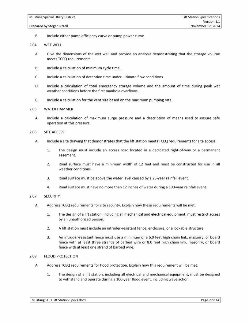
2.04 WET WELL
A. Give the dimensions of the wet well and provide an analysis demonstrating that the storage volume meets TCEQ requirements.
B. Include a calculation of minimum cycle time.
C. Include a calculation of detention time under ultimate flow conditions.
D. Include a calculation of total emergency storage volume and the amount of time during peak wet weather conditions before the first manhole overflows.
E. Include a calculation for the vent size based on the maximum pumping rate.
2.05 WATER HAMMER
A. Include a calculation of maximum surge pressure and a description of means used to ensure safe operation at this pressure.
2.06 SITE ACCESS
A. Include a site drawing that demonstrates that the lift station meets TCEQ requirements for site access:
1. The design must include an access road located in a dedicated right‐of‐way or a permanent easement.
2. Road surface must have a minimum width of 12 feet and must be constructed for use in all weather conditions.
3. Road surface must be above the water level caused by a 25‐year rainfall event.
4. Road surface must have no more than 12 inches of water during a 100‐year rainfall event.
2.07 SECURITY
A. Address TCEQ requirements for site security. Explain how these requirements will be met:
1. The design of a lift station, including all mechanical and electrical equipment, must restrict access by an unauthorized person.
2. A lift station must include an intruder‐resistant fence, enclosure, or a lockable structure.
3. An intruder‐resistant fence must use a minimum of a 6.0 feet high chain link, masonry, or board fence with at least three strands of barbed wire or 8.0 feet high chain link, masonry, or board fence with at least one strand of barbed wire.
2.08 FLOOD PROTECTION
A. Address TCEQ requirements for flood protection. Explain how this requirement will be met:
1. The design of a lift station, including all electrical and mechanical equipment, must be designed to withstand and operate during a 100‐year flood event, including wave action.

Mustang Special Utility District Lift Station Specifications Version 1.1Prepared by Steger Bizzell November 12, 2014
Mustang SUD Lift Station Specs.docx Page 3 of 14
2.09 ODOR CONTROL
A. Include an analysis of the wet well detention times for initial and ultimate build out and the likelihood of odor problems.
B. Unless Mustang specifies in writing that odor control will not be an issue at the site, include a design for an odor‐control system.
PART 3 ‐ GENERAL REQUIREMENTS
3.01 SCOPE
A. Developer shall furnish and install all equipment and materials and furnish all labor, tools and supplies necessary to completely construct and render operational the lift station(s) indicated on the plans in accordance with these specifications, including the installation of the items necessary to furnish a complete and functional unit, including electrical service and all necessary terminal boxes, control panels, electric conduit and wiring.
B. Lift station shall meet TCEQ requirements.
C. Electrical conduits, conductors, and equipment shall comply with NEC requirements.
PART 4 ‐ WET WELL
4.01 DUPLEX STATIONS
A. Pump station wet well shall be Flygt TOP series pre‐engineered duplex pump station or approved equal.
B. Discharge piping shall be 316 SST.
4.02 TRIPLEX OR LARGER STATIONS
A. Developer’s engineer shall provide specifications for review by Mustang’s engineer.
PART 5 ‐ VALVE VAULT
5.01 EMERGENCY BYPASS CONNECTION
A. An emergency bypass/pump‐in connection shall be installed on the common discharge piping making it possible to use an emergency pump and discharge hose to operate the lift station.
B. A resilient seat gate valve shall be installed between discharge piping and bypass connection.
C. Bypass connection shall be Camlock male coupler with cap.
5.02 FLOW METER
A. Valve vault shall include flow meter as specified in the Instrumentation section.
PART 6 ‐ PUMPS
6.01 GENERAL
A. Developer shall furnish all labor, materials, equipment and incidentals required to provide wastewater pumps as specified herein.

Mustang Special Utility District Lift Station Specifications Version 1.1Prepared by Steger Bizzell November 12, 2014
Mustang SUD Lift Station Specs.docx Page 4 of 14
6.02 MANUFACTURERS
A. The pump, mechanical seals and motor shall be from the same manufacturer.
B. Pumps shall be Flygt N‐pump series for semi‐permanent installation or approved equal.
C. Specifications for pump, motor, cable, shaft, impeller, protection, submittals, testing, and start‐up service shall be consistent with Flygt’s Pump Specs.
6.03 PUMP
A. Furnish and install _ heavy‐duty, submersible, non‐clog wastewater pump(s). Each pump shall be equipped with a _ HP submersible electric motor connected for operation on 460 volts, 3 phase, 60 hertz, 4 wire service, with _ feet of submersible cable (SUBCAB) suitable for submersible pump applications.
B. The pump shall be supplied with a mating cast iron _______ inch discharge connection and be capable of delivering _______ GPM at _______ FT. TDH. An additional point on the same curve shall be _____ GPM at _____ feet total head. Shut off head shall be _____ feet (minimum).
C. The pump shall be capable of handling a 3" spherical solid.
6.04 MOTOR
A. Motor voltage shall be 460 volts unless Mustang or Mustang’s engineer gives permission to use a lower utility voltage. In all cases, motor shall be 3‐phase.
B. Pump motors shall be inverter‐rated per NEMA MG1, Part 31. Motors shall be able to withstand a peak line‐to‐line voltage of 1600 volts.
6.05 SHIELDED POWER CABLE
A. The power cable shall be sized according to the NEC and ICEA standards and shall be of sufficient length to reach the junction box without the need of any splices. The power cable shall be of a shielded design in which an overall tinned copper shield is included and each individual phase conductor is shielded with an aluminum coated foil wrap. The outer jacket of the cable shall be oil resistant chlorinated polyethylene rubber. The cable shall be capable of continuous submergence underwater without loss of watertight integrity to a depth of 65 feet or greater.
PART 7 ‐ ELECTRICAL
7.01 SERVICE
A. Developer is responsible for coordinating service with the local electric utility company.
B. Three‐phase, 480V, grounded‐Y service is required. Any alternative requires signed permission from Mustang. In the event that permission is given for single‐phase service, pump motors shall still be 3‐phase and the VFDs will be sized appropriately to run on single‐phase input power.
C. Circuit breakers shall be used to protect from line faults and to disconnect pumps and control panel from the incoming power. Circuit breakers shall be thermal magnetic and sized to meet NEC requirements for motor controls.
Mustang Special Utility District Lift Station Specifications Version 1.1Prepared by Steger Bizzell November 12, 2014
Mustang SUD Lift Station Specs.docx Page 5 of 14
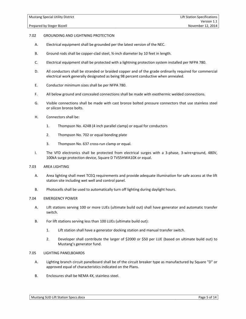
7.02 GROUNDING AND LIGHTNING PROTECTION
A. Electrical equipment shall be grounded per the latest version of the NEC.
B. Ground rods shall be copper‐clad steel, ¾‐inch diameter by 10 feet in length.
C. Electrical equipment shall be protected with a lightning protection system installed per NFPA 780.
D. All conductors shall be stranded or braided copper and of the grade ordinarily required for commercial electrical work generally designated as being 98 percent conductive when annealed.
E. Conductor minimum sizes shall be per NFPA 780.
F. All below ground and concealed connections shall be made with exothermic welded connections.
G. Visible connections shall be made with cast bronze bolted pressure connectors that use stainless steel or silicon bronze bolts.
H. Connectors shall be:
1. Thompson No. 424B (4 inch parallel clamp) or equal for conductors
2. Thompson No. 702 or equal bonding plate
3. Thompson No. 637 cross‐run clamp or equal.
I. The VFD electronics shall be protected from electrical surges with a 3‐phase, 3‐wire+ground, 480V, 100kA surge protection device, Square D TVS5HWA10X or equal.
7.03 AREA LIGHTING
A. Area lighting shall meet TCEQ requirements and provide adequate illumination for safe access at the lift station site including wet well and control panel.
B. Photocells shall be used to automatically turn off lighting during daylight hours.
7.04 EMERGENCY POWER
A. Lift stations serving 100 or more LUEs (ultimate build out) shall have generator and automatic transfer switch.
B. For lift stations serving less than 100 LUEs (ultimate build out):
1. Lift station shall have a generator docking station and manual transfer switch.
2. Developer shall contribute the larger of $2000 or $50 per LUE (based on ultimate build out) to Mustang’s generator fund.
7.05 LIGHTING PANELBOARDS
A. Lighting branch circuit panelboard shall be of the circuit breaker type as manufactured by Square "D" or approved equal of characteristics indicated on the Plans.
B. Enclosures shall be NEMA 4X, stainless steel.

Mustang Special Utility District Lift Station Specifications Version 1.1Prepared by Steger Bizzell November 12, 2014
Mustang SUD Lift Station Specs.docx Page 6 of 14
C. Main shall be equipped with solderless lugs. Bussing shall be of sequence type so that multi‐pole breakers can be substituted for single‐pole breakers without buss or assembly rearrangement.
D. Branch circuit breakers shall be of the Thermal Magnetic type, ITE Co. type or approved equal, having inverse time delay thermal trip on overloads and instantaneous magnetic trip on short circuits. These breakers shall employ quick‐make and quick‐break toggle mechanisms for manual operation as well as automatic operations. Automatic tripping shall be indicated by the breaker handle assuming a clearly distinctive position. The neutral bar shall have numbered terminals.
E. Cabinets for lighting panelboards shall have ample wiring gutters for all wires and connections. Hinged doors shall be equipped with spring catch and keyed lock. Panel trim shall be furnished for flush or surface trim as indicated. Inside of door shall have an index to identify each circuit.
7.06 CONDUITS
A. All conduit system materials and installation shall be in conformity with the National Electrical Code.
B. Conduits entering wet well shall be fitted with gas seals to prevent gases from entering electrical enclosures.
C. The minimum diameter for conduit shall be ½ inch. The minimum diameter for conduit in or under slab shall be ¾ inch.
D. Conduit buried underground or in or under slab shall be thick‐wall nonmetallic.
E. Exposed conduit shall be PVC‐coated galvanized steel conduit.
F. All pipe and conduit shall be provided with sleeves or thimbles where they pass through wall or slab construction.
PART 8 ‐ VARIABLE FREQUENCY DRIVES
8.01 GENERAL
A. Variable frequency drives are required.
B. Bypass starters shall be provided, either separately or integrated with the variable frequency drives, which will start the pumps in response to a high‐level condition in the event of a failure of the VFD control electronics.
8.02 ENCLOSURE
A. The variable frequency drives shall be contained in a stainless steel enclosure meeting NEMA 4X and UL 94 V‐O requirements.
B. The enclosure shall have a dead‐front outer door with provisions for padlocking.
C. A nameplate shall be permanently affixed to the panel and include the model number, voltage, number of phases, and horsepower rating.
D. A warning label against electric shock shall be permanently affixed to the outer door.
Mustang Special Utility District Lift Station Specifications Version 1.1Prepared by Steger Bizzell November 12, 2014
Mustang SUD Lift Station Specs.docx Page 7 of 14
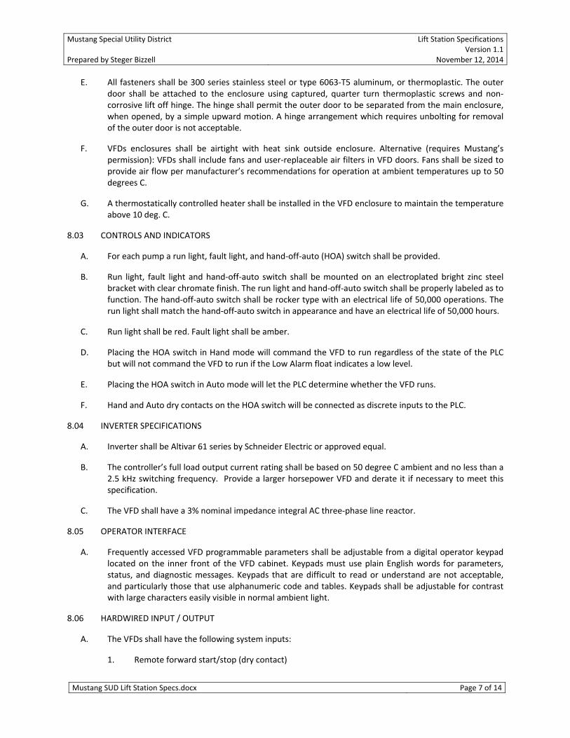
E. All fasteners shall be 300 series stainless steel or type 6063‐T5 aluminum, or thermoplastic. The outer door shall be attached to the enclosure using captured, quarter turn thermoplastic screws and non‐corrosive lift off hinge. The hinge shall permit the outer door to be separated from the main enclosure, when opened, by a simple upward motion. A hinge arrangement which requires unbolting for removal of the outer door is not acceptable.
F. VFDs enclosures shall be airtight with heat sink outside enclosure. Alternative (requires Mustang’s permission): VFDs shall include fans and user‐replaceable air filters in VFD doors. Fans shall be sized to provide air flow per manufacturer’s recommendations for operation at ambient temperatures up to 50 degrees C.
G. A thermostatically controlled heater shall be installed in the VFD enclosure to maintain the temperature above 10 deg. C.
8.03 CONTROLS AND INDICATORS
A. For each pump a run light, fault light, and hand‐off‐auto (HOA) switch shall be provided.
B. Run light, fault light and hand‐off‐auto switch shall be mounted on an electroplated bright zinc steel bracket with clear chromate finish. The run light and hand‐off‐auto switch shall be properly labeled as to function. The hand‐off‐auto switch shall be rocker type with an electrical life of 50,000 operations. The run light shall match the hand‐off‐auto switch in appearance and have an electrical life of 50,000 hours.
C. Run light shall be red. Fault light shall be amber.
D. Placing the HOA switch in Hand mode will command the VFD to run regardless of the state of the PLC but will not command the VFD to run if the Low Alarm float indicates a low level.
E. Placing the HOA switch in Auto mode will let the PLC determine whether the VFD runs.
F. Hand and Auto dry contacts on the HOA switch will be connected as discrete inputs to the PLC.
8.04 INVERTER SPECIFICATIONS
A. Inverter shall be Altivar 61 series by Schneider Electric or approved equal.
B. The controller’s full load output current rating shall be based on 50 degree C ambient and no less than a 2.5 kHz switching frequency. Provide a larger horsepower VFD and derate it if necessary to meet this specification.
C. The VFD shall have a 3% nominal impedance integral AC three‐phase line reactor.
8.05 OPERATOR INTERFACE
A. Frequently accessed VFD programmable parameters shall be adjustable from a digital operator keypad located on the inner front of the VFD cabinet. Keypads must use plain English words for parameters, status, and diagnostic messages. Keypads that are difficult to read or understand are not acceptable, and particularly those that use alphanumeric code and tables. Keypads shall be adjustable for contrast with large characters easily visible in normal ambient light.
8.06 HARDWIRED INPUT / OUTPUT
A. The VFDs shall have the following system inputs:
1. Remote forward start/stop (dry contact)

Mustang Special Utility District Lift Station Specifications Version 1.1Prepared by Steger Bizzell November 12, 2014
Mustang SUD Lift Station Specs.docx Page 8 of 14
2. Remote reverse start/stop (dry contact)
3. Remote fault reset (dry contact)
4. Speed reference interface (4‐20mA)
B. The VFDs shall have the following system outputs:
1. Remote mode (dry contact) – from HOA switch on VFD door
2. Local mode (dry contact) – from HOA switch on VFD door
3. Fault detected (dry contact)
4. VFD running (dry contact)
5. Motor frequency (4‐20mA)
C. Digital I/O shall be rated 12V to 260V AC or DC.
D. Analog interfaces shall be isolated.
8.07 COMMUNICATIONS
A. VFDs shall be configured for Modbus RTU communications using RS‐485. This will be connected to the telemetry unit provided by Mustang.
B. The Modbus interface shall support the following inputs to the drive:
1. Forward start / stop
2. Reverse start / stop
3. Speed reference
4. Reset fault
C. The Modbus interface shall support the following outputs from the drive:
1. Actual speed
2. Input power
3. Fault detected
4. Motor voltage
5. Motor current
6. Fault code
8.08 CONFIGURATION
A. Developer is responsible for configuring VFD with pump motor nameplate data.
B. Developer is responsible for configuring the VFD with a linear voltage / Hz curve. Note: Some VFDs have an energy‐saving parabolic V/Hz curve by default, which is not suitable for lift station pumps.

Mustang Special Utility District Lift Station Specifications Version 1.1Prepared by Steger Bizzell November 12, 2014
Mustang SUD Lift Station Specs.docx Page 9 of 14
8.09 DELIVERY, STORAGE, AND HANDLING
A. Equipment shall be handled and stored in accordance with manufacturer's instructions. One (1) copy of these instructions shall be included with the equipment at time of shipment.
B. Developer shall coordinate the shipping of equipment with the VFD manufacturer for entry into the building.
C. Developer shall store the VFD(s) in a clean, dry and heated space.
D. The Installer shall protect the VFD(s) from dirt, water, condensation, construction debris and traffic.
E. During storage, the Installer shall connect internal space heaters (if specified) with temporary power.
8.10 SPARE MATERIALS
A. The following spare parts shall be furnished for each size drive:
1. Three of each type power and control fuse
2. Two power modules or 20%, whichever is greater
3. Two spare LEDs / lamps of each type used
4. Two spare control relays of each type used
5. Two sets of all replacement air filters if used
6. One set of all control printed circuit boards
7. Provide spare fuses equal to 10% of the installed quantity for primary and secondary control power transformer protection.
8.11 SUBMITTALS
A. Developer shall submit to Mustang, upon completion of project, electronic versions of the following:
1. Complete Bill of Materials indicating manufacturer’s part numbers, showing all quantities and descriptions.
2. Equipment Cut Sheets showing all ratings, listings, part numbers, and pertinent equipment specifications including VFD parameter settings.
3. As‐built shop drawings including electrical schematics and door layouts. Drawings should include all field installation as‐builts.
4. All applicable equipment manuals including installation & operation manuals.
5. Name and phone number for a local distributor for the spare parts.
8.12 WARRANTY
A. The VFD manufacturer shall provide a Parts and Labor warranty for the VFDs that extends 24 months from the date of start‐up or 18 months from date of “Project Acceptance”, whichever expires first.
B. The VFD manufacturer shall confirm this warranty as part of the submittal.
Mustang Special Utility District Lift Station Specifications Version 1.1Prepared by Steger Bizzell November 12, 2014
Mustang SUD Lift Station Specs.docx Page 10 of 14
PART 9 ‐ CONTROL PANEL
9.01 GENERAL
A. Developer shall furnish all labor, materials, equipment and incidentals required to install a complete and fully operational control panel to manually or automatically operate the equipment as specified in the mechanical and electrical equipment specifications, as well as all project drawings. This specification shall apply to all control panels provided as part of packaged equipment systems as well as all individual panels provided as separate entities.
B. The motor control panel shall be assembled and tested by a shop meeting U.L. Standard 508 for industrial controls.
C. The control panel shall comply with the NEC regulations and have a UL label. The panel shall contain all components required by the pump manufacture for starting and protection of the motor. Any features required by the pump manufacture for warranty of the pump shall be included in the control panel.
9.02 CONSTRUCTION
A. The controls for the pump shall be contained in a stainless steel NEMA 4X enclosure.
B. The enclosure shall have a dead‐front outer door with provisions for padlocking.
C. A warning label against electric shock shall be permanently affixed to the outer door.
D. All fasteners shall be 300 series stainless steel or type 6063T5 aluminum, or thermoplastic. The outer door shall be attached to the enclosure using captured, quarter turn thermoplastic screws and non‐corrosive lift off hinge. The hinge shall permit the outer door to be separated from the main enclosure, when opened, by a simple upward motion. A hinge arrangement which requires unbolting for removal of the outer door is not acceptable.
E. A steel back panel with electroplated bright zinc and clear chromate finish shall be provided. A painted steel back panel will not be acceptable. The back panel shall be mounted on stainless steel bolts using stainless steel nuts and lock washers to maintain enclosure integrity and shall be used as the means for mounting the components in the enclosure.
F. Provide internal condensation and freezing protection with a thermostatically controlled heater. Thermostat shall be adjustable between 40F and 80F.
G. Furnish enclosures with vapor phase protective corrosion inhibitors equal to Hoffman A‐HCI‐5E or A‐HCI‐10E. Activate inhibitor upon delivery of the panel to the site. Do not store panels with inhibitors inactive.
9.03 TERMINAL BLOCKS
A. Terminal blocks shall be IEC style terminal blocks sized as required for the application. Type written labels shall be provided to identify each terminal. All terminal blocks shall be Allen‐Bradley 1492‐W4 or equal.
B. All terminal blocks shall be provided with a screw terminal pressure plate.
C. A minimum of 15% spare shall be provided
D. Provide an AC ground bus bar bonded to the metal of the panel with the required number of terminations for all field equipment.
Mustang Special Utility District Lift Station Specifications Version 1.1Prepared by Steger Bizzell November 12, 2014
Mustang SUD Lift Station Specs.docx Page 11 of 14
E. Provide an AC ground connection sized for the incoming power feed.
9.04 ELECTRICAL
A. The control panel electronics shall be protected from electrical surges with a single‐phase, 3‐wire, 480V, 50kA surge protection device, Square D TVS1HWA50X or equal.
B. The control panel electronics will be backed up with a 600VA (minimum) uninterruptible power supply.
C. All powered instruments, e.g., flow meters, shall be powered from the control panel receiving the signal from the device.
D. Instruments shall be powered using 24‐VDC power from the control panel rather than 120‐VAC power unless permission is granted by Mustang’s engineer.
E. PLC panels shall be provided with a receptacle for connection to a programmer’s laptop.
9.05 CONTROLS AND INDICATORS
A. Indicator lights shall be provided for Low Alarm, Reset, Lead, Lag, High Alarm levels. Lights shall be properly labeled as to function. Alarm lights shall be amber. Reset light shall be green. Lead and Lag lights shall be red.
B. Indicator lights shall be mounted on the inner door.
C. Indicator lights shall be mounted on electroplated bright zinc steel brackets with clear chromate finish.
9.06 AUDIOVISUAL ALARM
A. A flashing red alarm light shall be provided on top of the control panel. The alarm light shall be weatherproof and shatterproof with a minimum 4 inch diameter and 40 watt lamp.
B. An alarm horn shall be provided with an alarm silence button. The alarm horn shall be mounted on the left side of the enclosure with a weatherproof back box. The horn shall provide a signal of not less than 90db at 10 feet.
C. The alarm light and horn shall be used to signal the High Level alarm.
9.07 PROGRAMMABLE LOGIC CONTROLLER
A. The PLC shall be as manufactured by Allen‐Bradley. The PLC shall be a MicroLogix 1400, Catalog number 1766‐L32BWA, with I/O expansion modules as required.
B. Use of the low‐resolution, onboard analog I/O on the PLC (model 1766‐L32BWAA) is not permitted.
9.08 RELAY LOGIC OVERRIDE BYPASSING PLC AND VFDS
A. In response to a High Alarm level, as indicated by the High Alarm level float switch:
1. Both Lead and Lag pumps will be energized and will remain energized until either the Reset level or Low Alarm level is reached as indicated by the float switches.
2. The High Alarm audiovisual alarm will be energized.
B. This logic shall be independent of the PLC and shall operate even in the absence of the PLC.

Mustang Special Utility District Lift Station Specifications Version 1.1Prepared by Steger Bizzell November 12, 2014
Mustang SUD Lift Station Specs.docx Page 12 of 14
C. This logic will control starters that bypass the variable frequency drives.
9.09 INSTRUMENTATION
A. Terminal blocks with box type lugs shall be supplied to terminate all wiring for floats and heat and seal sensors for the pump. The terminal blocks for the float connections shall be on the pump controller.
B. All wiring to be labeled and neatly arranged in wireways.
C. PLC Inputs and Outputs
1. All discrete inputs, including configured spares, to be connected through DIN‐rail mounted relays with LEDs indicating energized state.
2. All discrete outputs, including configured spares, to be connected through 24‐VDC, DIN‐rail mounted relays with LEDs indicating energized state.
3. All analog inputs and outputs, including configured spares identified on I/O schedules, to be connected through 250 mA fused terminal blocks and isolators with passive 4‐20mA inputs and active 4‐20mA outputs (to 500‐ohm). Isolators to be Allen‐Bradley 931H‐C2C2D‐DC or approved equal.
4. Control relays driving DC loads shall be equipped with surge suppressing diodes.
D. VFDs
1. All IO points listed in the VFD section of this document shall be connected to the PLC.
E. Pump Motors
1. Each motor shall be configured with over‐temperature and leakage sensors connected to the PLC as discrete inputs.
F. Floats
1. A float‐mounting bracket shall be provided with strain relief that support and hold the level control cords. Continuous cords are to run from pump(s) and level controls to a control panel or junction box. No splices shall be made in the wiring. The bracket shall be fabricated from stainless steel or steel coated for corrosion resistance. The float bracket shall be attached to the access frame with 300 series stainless steel fasteners. A dielectric spacer should be installed when bolting to an aluminum access frame.
2. Floats shall be provided to detect the following levels as specified on the drawings: Low Alarm, Reset, Lead, Lag, and High Alarm.
G. Level Sensor
1. Submersible level transmitter shall be of the ultrasonic type, EchoSonic II series by FlowLine, or approved equal.
H. Flow Meter
1. Flow meter shall be Toshiba Electromagnetic Flowmeter series GF632 (detector) and LF622 (remote convertor) or equal approved by Mustang’s engineer.
Mustang Special Utility District Lift Station Specifications Version 1.1Prepared by Steger Bizzell November 12, 2014
Mustang SUD Lift Station Specs.docx Page 13 of 14
2. Lining material shall be FEP.
3. Electrode material shall be Hastelloy C.
4. When used with non‐metal pipes or with lined pipes, a grounding ring shall be installed per manufacturer’s guidelines to ensure an electrical connection to the liquid in the pipe.
5. A submersion potting kit shall be used per manufacturer’s guidelines to completely seal the electrical connections to the detector.
6. The meter shall be installed according to the manufacturer’s guidelines including constraints on upstream and downstream lengths between flowmeter and any sources of turbulence.
7. The meter shall be configured to provide both discrete pulse and analog (4‐20 mA) flow signals.
8. The meter shall be configured to produce several pulses per second at the highest expected flows.
I. Discharge Pressure Sensor
1. A 4‐20 mA pressure transmitter with range suitable for the largest expected transient pressure shall be installed on the point closest to the pumps on the common discharge header.
J. Line Voltage Detection Relay
1. A line‐voltage relay shall provide a dry‐contact input to the PLC to signal loss of utility power.
9.10 CONTROL PROGRAM
A. The PLC program shall provide continuous monitoring of the wet well level via analog level signal. The program shall start and stop pump based upon wet well level and programmed setpoints. The program shall use the float switches as backup in the event of analog signal failure.
B. The pump controller shall alternate pumps.
9.11 TELEMETRY
A. The hardware for communicating with Mustang’s SCADA system, including relaying alarm information per TCEQ requirements, will be provided by Mustang.
B. To support the telemetry electronics, developer shall provide:
1. Sufficient spare capacity in the 24‐volt DC power supply to drive a 1‐amp load.
2. A 1‐amp fused switch downstream of the 24‐volt DC power supply dedicated to the telemetry electronics.
3. A 10” x 10” empty area on the subpanel.
4. A DIN‐rail mounted Ethernet switch to provide connectivity among PLC, telemetry device, and laptop.
9.12 SUBMITTALS
A. Developer shall submit to Mustang, upon completion of project, electronic versions of the following:

Mustang Special Utility District Lift Station Specifications Version 1.1Prepared by Steger Bizzell November 12, 2014
Mustang SUD Lift Station Specs.docx Page 14 of 14
1. Complete Bill of Materials indicating manufacturer’s part numbers, showing all quantities and descriptions.
2. Equipment Cut Sheets showing all ratings, listings, part numbers, and pertinent equipment specifications.
3. As‐built shop drawings including electrical schematics and door layouts. Drawings should include all field installation as‐builts.
4. All applicable equipment manuals including installation & operation manuals.
PART 10 ‐ OTHER
10.01 TRAINING
A. Developer shall provide a training session for up to 5 Mustang's representatives for 1 normal workday with a maximum of 1 trip at a job site location determined by Mustang. Training and instruction time shall be in addition to that required for start‐up service.
B. The manufacturer’s qualified representative shall conduct the training.
C. The training program shall consist of the following:
1. Instructions on the proper operation of the equipment.
2. Instructions on the proper maintenance of the equipment.
END OF DOCUMENT