lpc1768 hplus ex user manual - coinel technology … hplus ex_user manual.pdf · 2015-06-23 ·...
TRANSCRIPT

LPC176x HPLUS EX www.coineltech.com
http://coineltech.com/shop/ Revision 1 1
LPC176x HPLUS EX User Manual
www.coineltech.com

LPC176x HPLUS EX www.coineltech.com
http://coineltech.com/shop/ Revision 1 2
Designed by
CoiNel Technology Solutions LLP
No-816, 2nd Floor, 4th B Cross, 9th A Main,
RPC Layout, Vijaynagar,
Bangalore-560040
State: Karnataka
Country: India
www.coineltech.com
For any questions or issues submit them to [email protected]
Designations used by companies to distinguish their products are often claimed as trademarks. In all instances where CoiNel is
aware of trademark claim, the product name appears in initial capital letters, in all capital or in accordance with the vendor’s
capitalization preference. Users should contact appropriate companies for more complete information on trademark and trademark
registrations. All trademarks and registered trademarks in this manual are the property of their respective holders.
No part of this manual may be reproduced or distributed in any form or by any means, or stored in the database or retrieval system,
without the prior written permission from CoiNel Technology Solutions LLP; with the exception that the listings may be entered,
stored and executed in a computer system, but they may not be reproduced.
The content in this manual are presented for instruction value. The details have been carefully tested, but are not guaranteed for
any particular purpose. CoiNel Technology Solutions does not offer any warranties and does not guarantee the accuracy,
adequacy, or completeness of any information herein and is not responsible for any errors or omissions. CoiNel Technology
Solutions LLP assumes no liability for damages resulting from use of such information in this manual or for any infringement of
intellectual property rights of third parties that would result from use of this information.
This evaluation board/kit is intended for use for ENGINEERING DEVELOPMENT, DEMONSTRATION and EDUCATION OR
EVALUATION PURPOSES ONLY and is not considered by CoiNel Technology Solutions LLP to be a finished end-product fit for
general consumer use. Persons handling the product(s) must have electronics training and observe good engineering practice
standards. As such, the goods being provided are not intended to be complete in terms of required design-, marketing-, and/or
manufacturing related protective considerations, including product safety and environmental measures typically found in end
products that incorporate such semiconductor components or circuit boards.
The user assumes all responsibility and liability for proper and safe handling of the goods. Further, the user indemnifies CoiNel
Technology Solutions LLP from all claims arising from the handling or use of the goods. Due to the open construction of the
product, it is the user’s responsibility to take any and all appropriate precautions with regard to electrostatic discharge. EXCEPT
TO THE EXTENT OF THE INDEMNITY SET FORTH ABOVE, NEITHER PARTY SHALL BE LIABLE TO THE OTHER FOR ANY
INDIRECT, SPECIAL, INCIDENTAL, OR CONSEQUENTIAL DAMAGES.
CoiNel Technology Solutions LLP assumes no liability for applications assistance, customer product design, software performance,
or infringement of patents or services described herein.

LPC176x HPLUS EX www.coineltech.com
http://coineltech.com/shop/ Revision 1 3
Log:
The version of the development: Revision LPC176xHPLUS EX 1
Document Version: Manual_LPC176xHPLUS EX 1

LPC176x HPLUS EX www.coineltech.com
http://coineltech.com/shop/ Revision 1 4
TABLE OF CONTENTS:
1. INTRODUCTION 5
2. HANDLING WARNINGS 6
3. KIT DELIVARABLES 6
4. BOARD USE REQUIREMENTS 6
5. FUNCTIONAL BLOCK DIAGRAM 7
6. BOARD LAYOUT 8
7. HARDWARE RESOURCES 10
8. IO CONNECTOR DESCRIPTION 11
9. VALIDATING LPC176x HPLUS EX 20
10. ISP MODE PROGRAMMING 24

LPC176x HPLUS EX www.coineltech.com
http://coineltech.com/shop/ Revision 1 5
1. INTRODUCTION:
LPC176x HPLUS EX is optimized to save development time in typical embedded control
applications. The board allows the evaluation of the LPC176x series devices. It is an extension of
an LPC176x HPLUS and has a few important peripheral interfaces assembled for evaluation and
testing. The remaining interface options are given out for the external interface via standard
2.54mm berg connectors.
The functional details of the board are as follows-
USB Device and Host Connectivity Options.
Onboard 2 Serial Ports. (UART0 and UART3)
128x64 Pixels Graphical LCD connectivity port (Graphical LCD is not the part of the Board,
needs to be brought separately)
Ethernet with DP83848 PHY MAC.
SD Card (Micro) Interface.
Analog input via AD0.5
I/O pin out.
Onboard Reset and ISP Switches.
On Board Power Supply Circuit for +5V and +3.3V (USB or external Power Source input
options)
On Board 12 MHz Oscillator.
32.768 KHz Clock for RTC. Option for a CMOS Battery.
Onboard 20 pin JTAG connector for debugging/programming applications.
On board TFT Connector for 3.2inch TFT connector (with touch and without touch).
LED for Power Supply, USB, Ethernet and Test LED.
Power Supply – DC input 7.5 - 9V/ 500ma - 1A.
Board Dimensions 8.6 x 9.1 cm2. Material: FR4, Finish: ENIG.
LPC176x HPLUS EX www.coineltech.com
http://coineltech.com/shop/ Revision 1 6
2. HANDLING WARNINGS: The Kit must not be subjected to high electrostatic potentials.
General practice for working with static sensitive devices should be followed when working
with the LPC176x HPLUS EX.
Board must always be handled at properly designated work areas.
When not being used, the board must be enclosed in the box and stored safely.
Avoid touching the circuits or components.
Stacking of circuit boards and assemblies should be avoided to prevent physical damage
3. KIT DELIVERABLES: LPC176x HPLUS EX Board.
USB Cable. (AB)
CD that contains, KEIL evaluation version installer, Flash Magic Installer, schematics, user
manual and related documents, hex files for experiments, Keil project and workspace for
implementing various peripherals and few example project codes.
4. BOARD USE REQUIREMENTS: To test and evaluate the board, we recommend the following configurations
PC with 2.0 GHz or higher CPU, 512 MB or above RAM, USB Port, Serial Port and
Ethernet Port. (Will need a Parallel Port if a Parallel JTAG is being used)
Operating System (We recommend Windows XP, since most of our testing is done on
same platform, although other OS can also be used)
Integrated Development Environment (We recommend Keil 4. Other compatible IDE can be
used)
Debugging/Programming Tool (We recommend HJTAG, Other compatible tools can be
used)
To test all the features of the board, you would also require a USB Cable (A to B), Ethernet
cable (straight), a Micro SD Card, DC power jack (7.5V-9V/1Amp DC). If you also need to
test the TFT, you will need a 3.2 inch TFT Board provided by CoiNel.

LPC176x HPLUS EX www.coineltech.com
http://coineltech.com/shop/ Revision 1 7
5. FUNCTIONAL BLOCK DIAGRAM OF LPC176x HPLUS EX: .
ARM Cortex M3 LPC176x
DP83848 PHY 10/100 Mbps Magnetics RJ45
Micro SD CARD
USB HOST
USB END DEVICE
3.2 inch TFT/Touch Screen Connectivity (Via SPI - Optional)
TEST LED
ISP/Interrupt Switch
Reset Switch
POT for ADC
JTAG DEBUG
Power Out 3.3V and 5V
12 MHz Clock
32.768 KHz Clock for RTC Battery Backup option
Pin Out for remaining IO Ports
2 SERIAL PORTS
128x64px Graphical LCD connectivity option

LPC176x HPLUS EX www.coineltech.com
http://coineltech.com/shop/ Revision 1 8
6. BOARD LAYOUT:
TOP VIEW

LPC176x HPLUS EX www.coineltech.com
http://coineltech.com/shop/ Revision 1 9
BOTTOM VIEW

LPC176x HPLUS EX www.coineltech.com
http://coineltech.com/shop/ Revision 1 10
7. HARDWARE RESOURCES:
BOARD Connections
The above figure shows the connectivity options available on LPC176x HPLUS EX.
LPC176x HPLUS EX www.coineltech.com
http://coineltech.com/shop/ Revision 1 11
8. I/O CONNECTOR DESCRIPTION:
The details of the IO connections are as follows
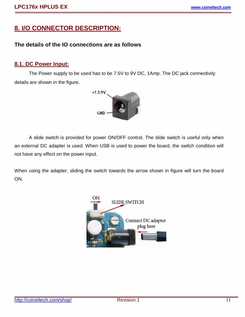
8.1. DC Power Input: The Power supply to be used has to be 7.5V to 9V DC, 1Amp. The DC jack connectivity
details are shown in the figure.
A slide switch is provided for power ON/OFF control. The slide switch is useful only when
an external DC adapter is used. When USB is used to power the board, the switch condition will
not have any effect on the power input.
When using the adapter, sliding the switch towards the arrow shown in figure will turn the board
ON.

LPC176x HPLUS EX www.coineltech.com
http://coineltech.com/shop/ Revision 1 12
8.2. JTAG 20 Pin Box Header: The box header will be used to connect the JTAG for Debug/Programming. A 20 Pin IO
Cable can be connected here which connects from a Parallel/USB JTAG. For more details on
JTAG, check www.coineltech.com
8.3. Micro SD Card Connector: The correct way of inserting the SD card is given below. The SD Card is connected to SPI0
Pins via jumpers. Pressing the card in the direction shown will lock the card once it will fully and
properly inserted.
Note: To remove the card, press the card gently in the same direction shown above and then
letting it loose. The card will easily pop out and can be removed.

LPC176x HPLUS EX www.coineltech.com
http://coineltech.com/shop/ Revision 1 13
8.4. Ethernet: The correct way to plug the connector is given in the figure. Press the connector in the
direction shown and the connector will lock up properly when it is fully connected.
An Ethernet straight through cable is used for testing. The recommended connection of the
cable is also given.

LPC176x HPLUS EX www.coineltech.com
http://coineltech.com/shop/ Revision 1 14
8.5. USB CONNECTIONS:
The USB provided can either be used as a HOST or an End Device. The USB A Connector
is used for the HOST interface, while USB B type for the end device. The jumper setting at J15
needs to be changed depending on whether the USB is used as a HOST or End Device.
The details of connections are given below.

LPC176x HPLUS EX www.coineltech.com
http://coineltech.com/shop/ Revision 1 15
8.6. Analog Input:
8.7. Reset and ISP Switch:
These switches provided can be used for resetting the CPU and ISP (In system
programming) mode. The details of programming the board in ISP mode is given in detail in
programming section.

LPC176x HPLUS EX www.coineltech.com
http://coineltech.com/shop/ Revision 1 16
8.8. Serial Ports: Onboard 2 Serial ports are provided i.e. UART0 & UART3. The signals are RS232 logic
compatible, so it can be directly connected to Computer Serial Port. The UART0 can be used for
ISP mode programming. The ISP mode programming detail is provided in programming section.
The UART module number is written on the rear side of the board below RS232 connectors.
8.9. Graphical LCD Connector: 128x64 Pixels Graphical display can be directly connected to this connector. All the
graphical LCD’s are not compatible. The Compatible Graphical display is available at
www.coineltech.com/shop
LPC176x HPLUS EX www.coineltech.com
http://coineltech.com/shop/ Revision 1 17
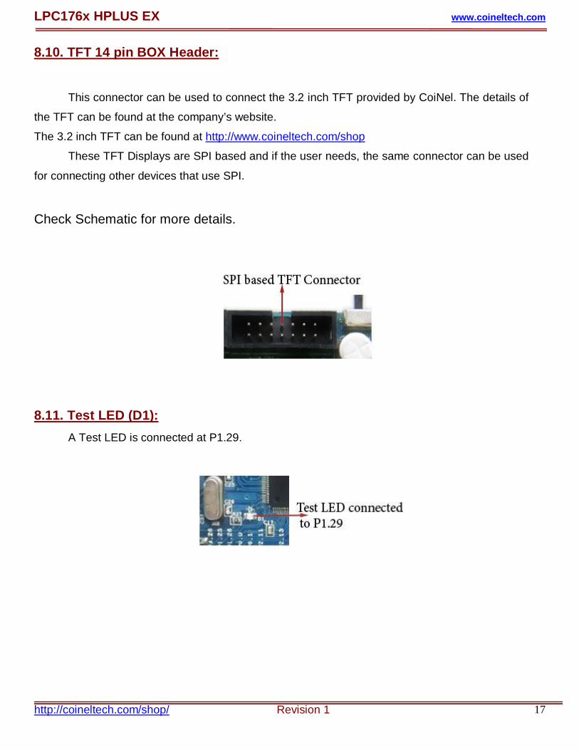
8.10. TFT 14 pin BOX Header:
This connector can be used to connect the 3.2 inch TFT provided by CoiNel. The details of
the TFT can be found at the company’s website.
The 3.2 inch TFT can be found at http://www.coineltech.com/shop
These TFT Displays are SPI based and if the user needs, the same connector can be used
for connecting other devices that use SPI.
Check Schematic for more details.
8.11. Test LED (D1): A Test LED is connected at P1.29.

LPC176x HPLUS EX www.coineltech.com
http://coineltech.com/shop/ Revision 1 18
8.12. Jumper Description: The details of the jumper connections are given below 8.12.1. J9 (Jumper for SD Card Connections):
8.12.2.J15 (Jumper for USB HOST or End Device Connections) :
LPC176x HPLUS EX www.coineltech.com
http://coineltech.com/shop/ Revision 1 19
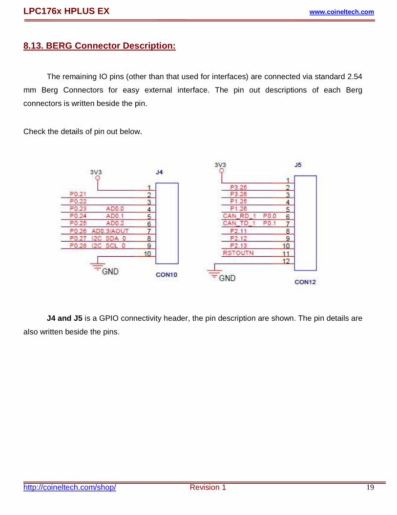
8.13. BERG Connector Description:
The remaining IO pins (other than that used for interfaces) are connected via standard 2.54
mm Berg Connectors for easy external interface. The pin out descriptions of each Berg
connectors is written beside the pin.
Check the details of pin out below.
J4 and J5 is a GPIO connectivity header, the pin description are shown. The pin details are
also written beside the pins.

LPC176x HPLUS EX www.coineltech.com
http://coineltech.com/shop/ Revision 1 20
9. VALIDATING LPC176x HPLUS EX: 9.1. Powering the Board:
The board can be powered using an adapter or through the USB. Connect the adapter
(7.5V-9V/ 1 Amp) to the DC Jack provided and slide the switch towards ON Position. The details
are shown below.
You can also power the board using USB by connecting the USB A to B Connector as
shown.
When the Power is applied, the POWER LED (D6 beside the DC Jack) will turn ON indicating
board power up.
Note: To test the board for the first time, you can use only USB for powering the board.

LPC176x HPLUS EX www.coineltech.com
http://coineltech.com/shop/ Revision 1 21
9.2. Detecting the USB:
The LPC176x HPLUS EX comes with a preloaded program to test LED and USB End
device functionality.
To test this, you need to open Device Manager.
The operating system used is Windows XP.
Steps to open Device Manager are as follows-
1. Right click on My Computer and left click on Manage Options as shown below
LPC176x HPLUS EX www.coineltech.com
http://coineltech.com/shop/ Revision 1 22
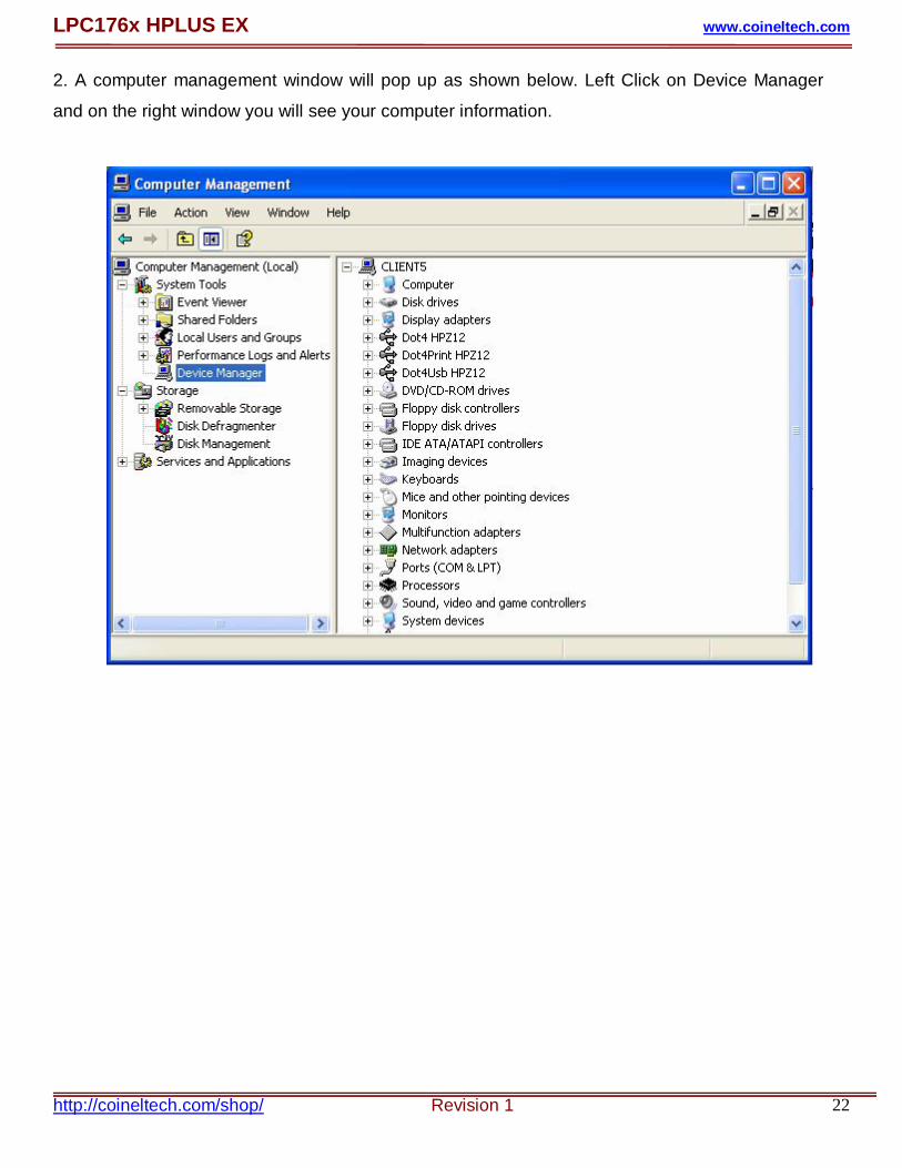
2. A computer management window will pop up as shown below. Left Click on Device Manager
and on the right window you will see your computer information.

LPC176x HPLUS EX www.coineltech.com
http://coineltech.com/shop/ Revision 1 23
3. Connect the USB cable (A to B type) to the PC and B side to LPC176x HPLUS EX Board. You
will see that the TEST LED will blink 5 times and at the 6th time, the test led will be ON
continuously and the USB LEDs (D8 and D9) will be ON once the USB is enumerated as the end
device and you will see that the device is detected as a human interface device and this can be
seen on the device manager. The changes seen in the device manager will be as follows.
The changes above indicate the board has been detected as a HID. One you see this you would
have evaluated the board for the first time.
Note: You can remove and re plug the USB or press reset switch to check and see the changes
all over again.

LPC176x HPLUS EX www.coineltech.com
http://coineltech.com/shop/ Revision 1 24
10. ISP MODE PROGRAMMING: You need to have LPC176x HPLUS EX Board, Serial cable, Desktop PC, Flash Magic
Software and precompiled Hex File.
Follow the Steps is below:
Power ON LPC176x HPLUS EX Board.
Connect Serial Cable Between UART0 of Module and PC.
Enter into the ISP Programming mode by following procedure.

LPC176x HPLUS EX www.coineltech.com
http://coineltech.com/shop/ Revision 1 25
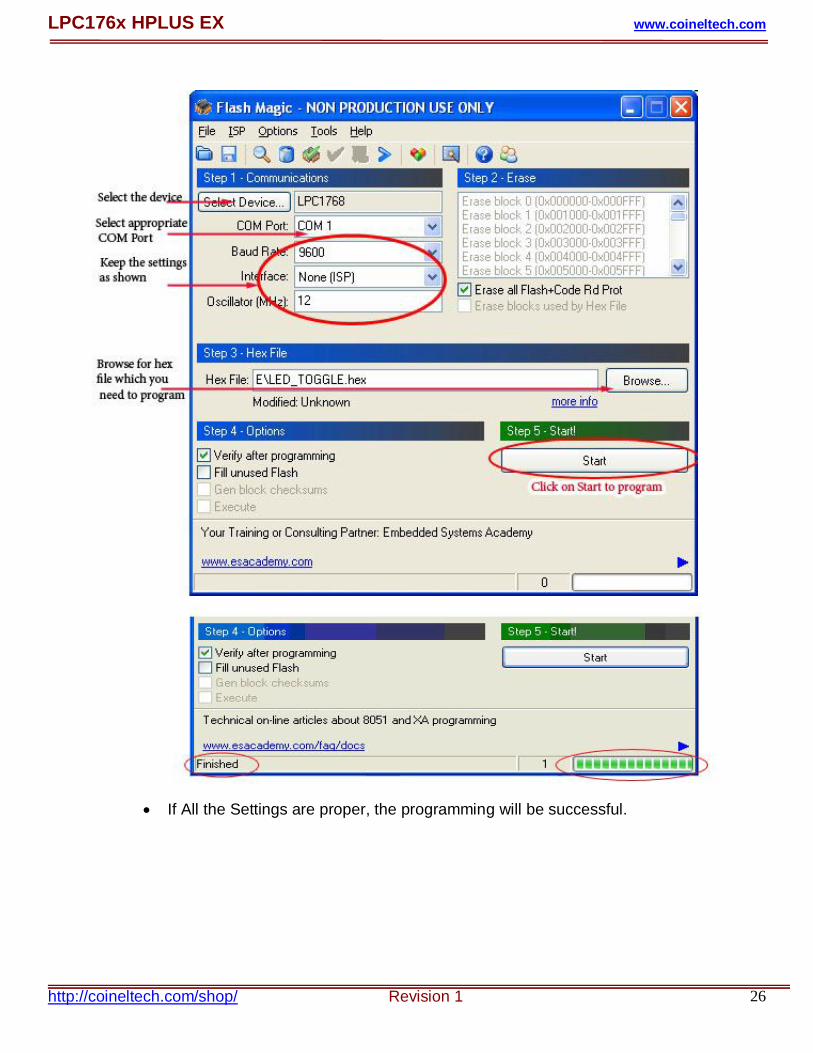
Open Flash Magic Software in PC.
Click on Options and select Advance Options.
In Advance Options Keep the Settings as shown below.
Click on OK after making changes
Keep the Settings as below in Flash Magic and Click on Start to program.
COM Port may not be COM1 in every PC, Check it in Ports (COM & LPT) in
Device Manager.
LPC176x HPLUS EX www.coineltech.com
http://coineltech.com/shop/ Revision 1 26
If All the Settings are proper, the programming will be successful.

LPC176x HPLUS EX www.coineltech.com
http://coineltech.com/shop/ Revision 1 27
AFTER-SALE SERVICE CoiNel is at your service, and we have special Technical Support Engineers to provide support and
consultation in forms of telephone and E-mail.
TEL: +91-80-23154423
Technical Support E-mail: [email protected]
For any questions or concerns submit them to [email protected]