lp product line - fluid equipment development companyfedco-usa.com/sites/default/files/lpd 125_250...
TRANSCRIPT
The LP Product Line is subject to US and foreign Patents Copyright ©2009 Fluid Equipment Development Company, LLC
The LP Product Line is subject to US and foreign Patents Copyright ©2009 Fluid Equipment Development Company, LLC
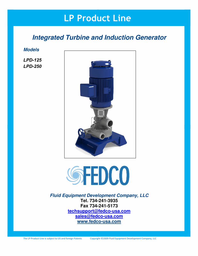
Integrated Turbine and Induction Generator
Models LPD-125LPD-250
Fluid Equipment Development Company, LLC Tel. 734-241-3935 Fax 734-241-5173
[email protected] [email protected] www.fedco-usa.com
LP Product Line
The LP Product Line is subject to US and foreign Patents Copyright ©2009 Fluid Equipment Development Company, LLC
INTRODUCTION
The Low Pressure (LP) product line developed by FEDCO consists of three basic modules that
can be connected in various combinations. The Modules are:
1. Pump Module (one or more sub-modules)
2. Turbine Module
3. Motor Drive Module
These modules can be combined into four products:
1. LPS – Pump and Motor modules - function as a typical low/medium pressure pump;
2. LPB – Pump and Turbine - a low cost turbocharger for low/medium pressure;
3. LPH – Pump, Turbine and Motor modules – feed pump with integrated brine
recovery turbine;
4. LPD – Turbine and Motor modules – generates electricity from brine hydraulic
energy.
ALL LP products use the patented FEDCO thrust bearing design which absorb the entire pump
thrust load, thereby protecting the motor bearings from any thrust loads associated with the
pump or turbine.
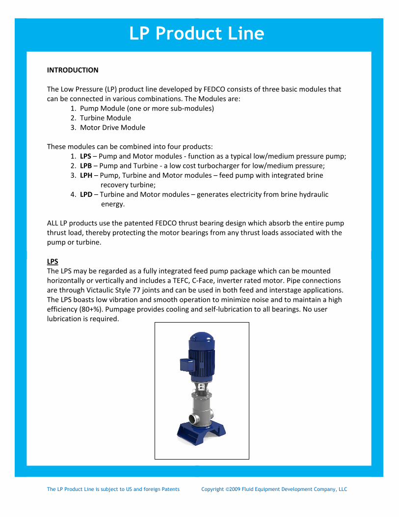
LPS
The LPS may be regarded as a fully integrated feed pump package which can be mounted
horizontally or vertically and includes a TEFC, C-Face, inverter rated motor. Pipe connections
are through Victaulic Style 77 joints and can be used in both feed and interstage applications.
The LPS boasts low vibration and smooth operation to minimize noise and to maintain a high
efficiency (80+%). Pumpage provides cooling and self-lubrication to all bearings. No user
lubrication is required.
LP Product Line
The LP Product Line is subject to US and foreign Patents Copyright ©2009 Fluid Equipment Development Company, LLC
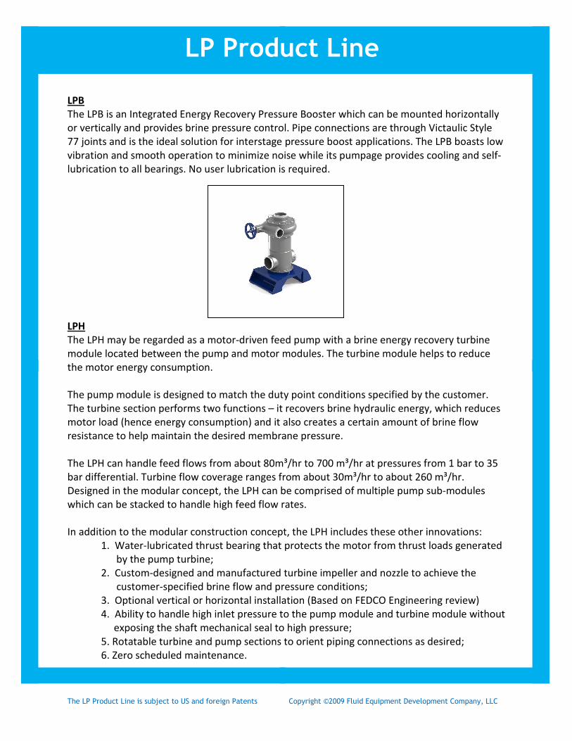
LPB
The LPB is an Integrated Energy Recovery Pressure Booster which can be mounted horizontally
or vertically and provides brine pressure control. Pipe connections are through Victaulic Style
77 joints and is the ideal solution for interstage pressure boost applications. The LPB boasts low
vibration and smooth operation to minimize noise while its pumpage provides cooling and self-
lubrication to all bearings. No user lubrication is required.
LPH
The LPH may be regarded as a motor-driven feed pump with a brine energy recovery turbine
module located between the pump and motor modules. The turbine module helps to reduce
the motor energy consumption.
The pump module is designed to match the duty point conditions specified by the customer.
The turbine section performs two functions – it recovers brine hydraulic energy, which reduces
motor load (hence energy consumption) and it also creates a certain amount of brine flow
resistance to help maintain the desired membrane pressure.
The LPH can handle feed flows from about 80m³/hr to 700 m³/hr at pressures from 1 bar to 35
bar differential. Turbine flow coverage ranges from about 30m³/hr to about 260 m³/hr.
Designed in the modular concept, the LPH can be comprised of multiple pump sub-modules
which can be stacked to handle high feed flow rates.
In addition to the modular construction concept, the LPH includes these other innovations:
1. Water-lubricated thrust bearing that protects the motor from thrust loads generated
by the pump turbine;
2. Custom-designed and manufactured turbine impeller and nozzle to achieve the
customer-specified brine flow and pressure conditions;
3. Optional vertical or horizontal installation (Based on FEDCO Engineering review)
4. Ability to handle high inlet pressure to the pump module and turbine module without
exposing the shaft mechanical seal to high pressure;
5. Rotatable turbine and pump sections to orient piping connections as desired;
6. Zero scheduled maintenance.
LP Product Line

The LP Product Line is subject to US and foreign Patents Copyright ©2009 Fluid Equipment Development Company, LLC
In comparison to standard turbochargers, the LPH has a particularly significant advantage – the
motor module can accommodate significant departures from the design conditions. For
example, if the brine flow or pressure is less than expected values, the motor can overcome the
deficit to provide the required power to the pump module to achieve the desired flow and
pressure.
Typical Applications for the LPH
Figure 1. shows the LPH applied as the high pressure feed pump with the integral turbine
recovering energy from the brine stream. Figure 2. Shows the LPH as an interstage booster,
which provides an increase in pressure between brine stages and recovers energy from the final
brine stage.
LP Product Line
FIGURE 1.
FIGURE 2.

The LP Product Line is subject to US and foreign Patents Copyright ©2009 Fluid Equipment Development Company, LLC
LPD
The LPD may be regarded as an integrated turbine and induction generator. The turbine
module drives the induction generator, generating electrical power with a line regenerative
Variable Frequency Drive (VFD)
The turbine module can accept multiple brine streams with independent pressure control.
Thrust Bearing Operation
The thrust bearing uses a “balance disc” to generate
counter-thrust to balance the thrust developed by the
pump and turbine modules thus protecting the motor
from thrust loads transmitted through the shaft.
The balance disc relies on the difference in pressure
between the pump discharge and the bearing low inlet
side to generate the counterforce. An excessively high
pressure on the inlet side or an unusually low pressure
on the discharge side reduces thrust capacity resulting
in possible heat generation and potential wear of the
balance disc.
Balance Disc
Bearing Drain Line
LP Product Line

The LP Product Line is subject to US and foreign Patents Copyright ©2009 Fluid Equipment Development Company, LLC
Preparation 1/16 The FEDCO LPD™ is designed to provide electrical energy generation from the brine stream in reverse osmosis (RO) systems. Please review this manual carefully before installing the LPD™. Keep the manual in a handy location for future reference.
Do not hesitate to contact FEDCO if there are any questions or comments.
Receiving and Inspection The LPD™ was tested before shipping to ensure it meets all performance requirements. To make sure the unit is ready for installation, please take the following steps: • Promptly inspect the crates or boxes carefully for damage • Report any damage to the freight company • Please save any documents that may be enclosed. The equipment should be uncrated and checked for possible hidden damage. Report any shortage to: FEDCO 800 Ternes Drive Monroe, MI 48162 USA 1-734-241-3935 Storage The LPD™ must be protected from moisture, sand, grit, and other foreign matter. Please do not remove the protective covers on the pipe connections until ready to install. Application Range The LPD™ should only be used within the following limits: Maximum temperature: 120 degrees F (49 deg C) Maximum particulate size: 20 micron Specific application limits are provided on the nameplate of each LPD™.
LP Product Line
Table of Contents
INSTALLATION & OPERATION Preparation 1 Installation/Operation 2 Start-up 4 MAINTENANCE Troubleshooting 5 Shaft Seal Replacement 7 Thrust Bearing Inspection 8 MISCELLANEOUS Parts Identification 9 Return & Warranty 10 Operating Records 12 SAFETY 13

The LP Product Line is subject to US and foreign Patents Copyright ©2009 Fluid Equipment Development Company, LLC
Installation/Operation 2/16 Terminology The following terminology is used to identify major components. The picture below shows a typical LPD™ model. Operating Principle Figures 2 illustrates a typical LPD application in an RO system. The membrane produces a high-pressure brine stream, which is directed back to the LPD™. The LPD™ recovers the pressure energy and discharges the brine at low pressure for disposal. Note that the LPD™ eliminates the brine valve normally used to control brine pressure. Also, the LPD™ does not require a brine disposal pump or gravity flow piping as the brine can be discharged against a backpressure.
LP Product Line
Induction Generator (Motor)
Regen Module
(can be rotated in
90 ° increments
Brine Outlet
Brine Inlet
Brine Control Valve
Figure 1
Figure 2

The LP Product Line is subject to US and foreign Patents Copyright ©2009 Fluid Equipment Development Company, LLC
Installation/Operation 3/16 Piping The piping attached to the LPD™ must not transmit piping strain to the unit. Low-pressure brine piping Note that the LPD™ can discharge brine against a backpressure. Therefore, a brine sump, gravity flow piping or a brine disposal pump is not needed. To prevent possible cavitation, the brine backpressure should not be less than about 5 psi. Please refer to the LPD data sheet provided by FEDCO for the backpressure required.
CAUTION - FLUSH THE PIPES!! Pipe debris such as welding slag can damage the unit. Thoroughly flush all pipes before installing the LPD™. Installing the Pipe Joints Be sure to properly lubricate the groove coupling gaskets. Be sure all joints are properly made and tightened before applying pressure to the system. Follow the coupling manufacturer’s instructions at all times!
LP Product Line
Low Pressure Brine to Drain
High Pressure Brine from Membrane
Figure 3

The LP Product Line is subject to US and foreign Patents Copyright ©2009 Fluid Equipment Development Company, LLC
Startup 4/16 The first startup is important for long-term efficiency and reliability of the LPD™. The unit is extremely simple and startup is easy. Just be sure that the pipes have been flushed and the following items have been checked. Before Startup 1. Verify that the feed and brine connections are correct; 2. Start the low pressure feed pump, purge air from all pipes and tanks and check for leaks; 3. Verify correct motor and VFD wiring 4. Valve Positioning • Set the LPD™ brine valve to the closed position. • Make sure other valves such as cleaning or brine bypass valves are closed. Initial Operation 1. Start the system as normal; 2. Measure the following and record on page 13 for future reference: • feed and brine pressures; • feed and brine flows; 3. Recovery Adjustment: • to increase permeate flow - close the LPD™ brine valve; • to reduce permeate flow - open the LPD™ brine valve. • IN SOME INSTANCES, THE BRINE VALVE WILL NOT BE USED. In this case, the VFD will act as a regenerative brake to control the brine flow. Off-Design Operation of LPD Your LPD™ was custom designed to meet the exact system conditions provided to FEDCO during the design phase. Changes in system recovery, and to a lesser extent, system pressures can affect performance and general operation of the LPD™. The integrated brine control valve is a valuable tool to aid in system control. If your system conditions deviate from the design conditions, the brine valve position will most likely need to be changed to provide the best boost possible and prevent internal damage to the thrust bearing and impeller. If, during startup, you notice that the flows and pressures vary from the design point, please contact FEDCO immediately and we will perform an off-design calculation to provide you with the optimal position for the brine valve. NOTE Every LPD™ is tested for pressure integrity, efficiency, and vibration before shipping.
LP Product Line
WARNING! Never force the brine valve beyond its full open position. Use only hand operation.
WARNING! If the brine valve retention plate is not fastened to turbine module, the valve can be completely unscrewed and can come completely out of the turbine module resulting in a high-pressure brine leak. See the parts identification drawing in this manual for more details.
The LP Product Line is subject to US and foreign Patents Copyright ©2009 Fluid Equipment Development Company, LLC
Troubleshooting 5/16 The LPD™ has two major functions - the first is to generate electrical power. The second is to help maintain brine flow and pressure at the desired values. Electrical Power Generation With the VFD in the Regen Mode, the Motor acts like a generator and the generated electricity must go somewhere. The regen unit passes it back into the incoming power grid/supply. Brine Pressure Adjustment Use the LPD™ brine valve to regulate brine flow and pressure as explained in the STARTUP procedure. Contact FEDCO if the desired pressure cannot be obtained. Leakage LPD ™ Brine Valve If brine leaks around the brine valve stem, the O-rings may need replacement. See the LPD™ Brine Valve repair section in this manual. Pipe Joints Depressurize and drain the system. Check the pipe joints for damaged gaskets, debris that could prevent sealing, etc. Reapply lubricant to the gaskets, reinstall, and tighten the joints. Miscellaneous Noise Sometimes, noise may be generated by resonance of pipe sections between Victaulic joints. This noise can greatly exceed the noise generated by the LPD™. Since the LPD™ has no cooling requirement; sound-absorbing material may be tightly packed around the LPD™. Be sure to maintain access to the brine control valve.
LP Product Line
The LP Product Line is subject to US and foreign Patents Copyright ©2009 Fluid Equipment Development Company, LLC
Troubleshooting 6/16 If the LPD™ appears not to be operating normally, please use the following checklist to help identify the potential problem. Note that most problems are not related to the LPD™.
Air Leaks • check inlet piping joints • check LPD™ shaft mechanical seal
Cavitation • check inlet pressure during LPD™operation • check flow rate • check outlet pressure and verify against design data sheet
Vibration or Unusual Noise Operating conditions • cavitation (see above) • flow rate is excessive • flow rate is less than minimum specified
Electrical Problems • check VFD Wiring • check motor wiring • check fuses (loss of phase)
Leakage Pipe Joints • disassemble grooved coupling joints, check for damaged gaskets or debris in gasket area
Shaft • damaged mechanical seal
Misalignment • check shaft coupling • check alignment of motor and LPD™
Internal Damage • see above
LP Product Line
The LP Product Line is subject to US and foreign Patents Copyright ©2009 Fluid Equipment Development Company, LLC
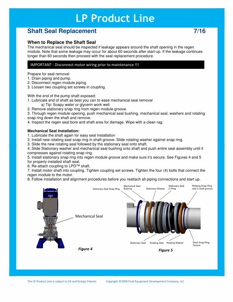
Shaft Seal Replacement 7/16 When to Replace the Shaft Seal The mechanical seal should be inspected if leakage appears around the shaft opening in the regen module. Note that some leakage may occur for about 60 seconds after start-up. If the leakage continues longer than 60 seconds then proceed with the seal replacement procedure.
IMPORTANT- Power to motor must be disconnected before maintenance ! ! ! Prepare for seal removal 1. Drain piping and pump. 2. Disconnect regen module piping. 3. Loosen two coupling set screws in coupling. With the end of the pump shaft exposed: 1. Lubricate end of shaft as best you can to ease mechanical seal removal a) Tip: Soapy water or glycerin work well 2. Remove stationary snap ring from regen module groove. 3. Through regen module opening, push mechanical seal bushing, mechanical seal, washers and rotating snap ring down the shaft and remove. 4. Inspect the regen seal bore and shaft area for damage. Wipe with a clean rag. Mechanical Seal Installation: 1. Lubricate the shaft again for easy seal installation 2. Install new rotating seal snap ring in shaft groove. Slide rotating washer against snap ring. 3. Slide the new rotating seal followed by the stationary seal onto shaft. 4. Slide Stationary washer and mechanical seal bushing onto shaft and push entire seal assembly until it compresses against rotating snap ring. 5. Install stationary snap ring into regen module groove and make sure it’s secure. See Figures 4 and 5 for properly installed shaft seal. 6. Re-attach coupling to LPD™ shaft. 7. Install motor shaft into coupling. Tighten coupling set screws. Tighten the four (4) bolts that connect the regen module to the motor. 8. Follow installation and alignment procedures before you reattach all piping connections and start up.
LP Product Line
IMPORTANT - Disconnect motor wiring prior to maintenance !!!
Mechanical Seal
Figure 4 Figure 5
Stationary Seal Snap Ring
Mechanical Seal Bushing Stationary Washer
Stationary Seal O Ring
Rotating Snap Ring
(sits in shaft groove)
Stationary Seal Rotating Seal Rotating Washer Shaft Snap Ring Groove

The LP Product Line is subject to US and foreign Patents Copyright ©2009 Fluid Equipment Development Company, LLC
LPD™ Thrust Bearing (Balance Disc) Inspection 8/16 When to Inspect The LPD™ thrust bearing (also referred to as the balance disc) may be inspected at intervals of approximately 4,000 hours of operating time (approximately every 6 months). Refer to the Parts Identification Drawing.
IMPORTANT Power to motor must be disconnected before maintenance ! ! ! Preparing for Inspection 1. Drain piping and LPD™. 2. Disconnect thrust bearing drain line from bottom of cavity cover. 3. Remove tubing connector from the cavity cover. - save tubing connector and O-ring 4. Remove (8) cavity cover bolts.
Thrust Bearing Inspection 1. Remove bearing cavity cover and cavity cover o-ring (be sure to save the O-ring). 2. Lock motor coupling with a strap (chain) wrench so pump shaft can’t move. 3. Remove hex head nut, lockwasher and washer. 4. Slide balance disc off shaft (note the balance disc key). Use balance disc removal holes to aid in removal. 5. Check balance disc for wear in the seal area. See Figure 6. - up to 0.020" of wear is acceptable. However, annual replacement is recommended. 6. Inspect the bearing area on the bearing holder for grooves, wear, etc. 7. Replace worn parts as needed.
Reassembly 1. Replace balance disc (with O-ring and key). Install balance disc washer, lockwasher and nut. - torque the nut to 50 ft-lbs. 2. Install bearing cavity cover and O-ring. 3. Firmly tighten cavity cover bolts to obtain metal-to-metal contact. - tighten to 54 ft-lbs. 4. Reconnect thrust bearing line. Be sure that throttle nipple tubing connector is clear of obstructions. 5. Remove strap wrench from motor coupling. 6. Fill piping with water and purge air. Follow normal start-up procedures.
NOTE • Minimum allowable thickness = 0.760 in • Use average of 4 measurements spaced around circumference
LP Product Line
Measure Near OD
Measure Here
Figure 6

The LP Product Line is subject to US and foreign Patents Copyright ©2009 Fluid Equipment Development Company, LLC
Part Identification Drawing 9/16
LP Product Line

The LP Product Line is subject to US and foreign Patents Copyright ©2009 Fluid Equipment Development Company, LLC
Parts Return and Warranty 10/16 Please contact FEDCO before returning any equipment You must have a Return Authorization Number (RAN) issued by FEDCO before we can accept any parts. All returned parts must be shipped prepaid to FEDCO with the RAN clearly marked on the package. We need this number to ensure proper handling of the returned parts and supply of new parts, if needed. Repair by FEDCO on equipment that is out-of-warranty will be warranted for three (3) months. Ask FEDCO for details of the repair warranty. Parts will be replaced in accordance with the FEDCO warranty. Use the following address to return parts: Field Service Department E-mail: [email protected] FEDCO Internet: www.fedco-usa.com 800 Ternes Drive Phone: +734-241-3935 Monroe, MI 48162 USA How to Return Parts to FEDCO 1. Provide FEDCO with the following information: • Serial number of unit • Description of why parts are being returned. 2. Wait for FEDCO to provide a Return Authorization Number. 3. Pack the unit in the original shipping crate or other suitable crate and clearly mark the Return Authorization Number on the outside of the crate. 4. Send unit, freight prepaid, to FEDCO at the above address.
LP Product Line

The LP Product Line is subject to US and foreign Patents Copyright ©2009 Fluid Equipment Development Company, LLC
11/16 LPD™ Warranty Fluid Equipment Development Company, LLC, (FEDCO), warrants its LPD™ to be free from defects in design, materials or workmanship for a period of 18 months from shipment of the product or 12 months from the date of installation of the product, whichever occurs first, when said product is operated in accordance with written instructions and is installed properly. If the LPD is altered or repaired without prior approval of FEDCO, all warranties are void. All equipment provided by FEDCO must be installed on a rigid, steel support structure and base capable of handling full loads during operation. Failure to do so will void warranty. All equipment must be installed such that there are no pipe stresses on FEDCO equipment. Failure to do so will void warranty. If the LPD is not installed as per FEDCO Installation and Operation Manual, any subsequent damage to the LPD will be excluded from the warranty. If any defects or malperformance occur during the warranty period, FEDCO's sole obligation shall be limited to alteration, repair or replacement at FEDCO's expense, F.O.B. factory, of any parts or equipment, which upon return to FEDCO and upon FEDCO's examination prove to be defective. All parts returned for warranty service must be shipped prepaid and include FEDCO's return authorization number. Equipment and accessories not manufactured by FEDCO are warranted only to the extent of and by the original manufacturer's warranty. FEDCO shall not be liable for damage or wear to equipment caused by abnormal conditions, excessive temperatures, and vibration or caused by corrosives, abrasives or foreign objects. The foregoing warranty is exclusive and in lieu of all other warranties, whether expressed or implied, including any warranty of merchantability or fitness for any particular purpose. In no event shall FEDCO be liable for consequential or incidental damages.
LP Product Line
The LP Product Line is subject to US and foreign Patents Copyright ©2009 Fluid Equipment Development Company, LLC
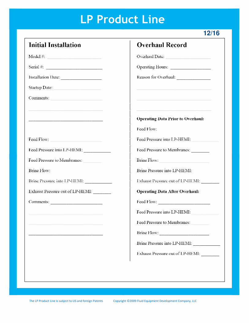
12/16
LP Product Line
The LP Product Line is subject to US and foreign Patents Copyright ©2009 Fluid Equipment Development Company, LLC
Safety Considerations
DANGER:
WARNING:
CAUTION:
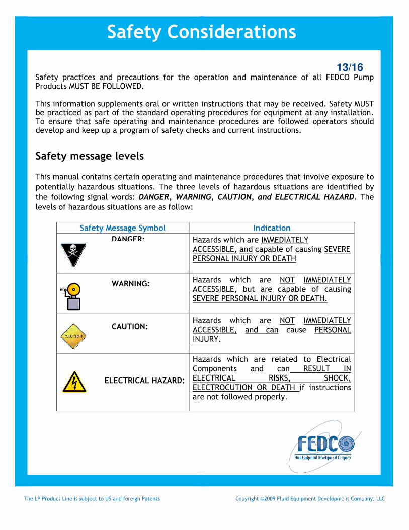
13/16 Safety practices and precautions for the operation and maintenance of all FEDCO Pump Products MUST BE FOLLOWED. This information supplements oral or written instructions that may be received. Safety MUST be practiced as part of the standard operating procedures for equipment at any installation. To ensure that safe operating and maintenance procedures are followed operators should develop and keep up a program of safety checks and current instructions. Safety message levels
This manual contains certain operating and maintenance procedures that involve exposure to
potentially hazardous situations. The three levels of hazardous situations are identified by
the following signal words: DANGER, WARNING, CAUTION, and ELECTRICAL HAZARD. The
levels of hazardous situations are as follow:
Safety Message Symbol Indication
Hazards which are IMMEDIATELY ACCESSIBLE, and capable of causing SEVERE PERSONAL INJURY OR DEATH
Hazards which are NOT IMMEDIATELY ACCESSIBLE, but are capable of causing SEVERE PERSONAL INJURY OR DEATH.
Hazards which are NOT IMMEDIATELY ACCESSIBLE, and can cause PERSONAL INJURY.
Hazards which are related to Electrical Components and can RESULT IN ELECTRICAL RISKS, SHOCK, ELECTROCUTION OR DEATH if instructions are not followed properly.
ELECTRICAL HAZARD:

The LP Product Line is subject to US and foreign Patents Copyright ©2009 Fluid Equipment Development Company, LLC
14/16
Safety
WARNING: · Pump and Safety precautions must be followed to prevent physical
injury to the operator.
· A pump is a pressure-generating device with rotating parts that can be hazardous. Any device containing generated pressure can rupture, explode or discharge its contents if it is sufficiently over-pressurized and may possibly result in personal injury, property damage, environmental damage and death. All necessary precautions must be exercised to insure over-pressurization does not occur. FEDCO will not accept responsibility for physical injury, damage or delays caused by a failure to observe the instructions in this manual.
· Installation, operation or maintenance of the pump unit in any manner which is not covered in this manual could cause damage to the equipment, serious injury or death. This includes any modification to the equipment or the use of parts not provided by FEDCO. If there is a question regarding the intended use of the equipment, please contact a FEDCO representative before proceeding.
· This manual clearly identifies accepted methods for disassembly of pump units and components. These methods must be strictly adhered to.
· Do not use the pump equipment for a different application than originally specified without the approval of a FEDCO representative.
· Never operate the pump equipment below the minimum rate flow, when dry, or without priming.
· Never operate the pump equipment without safety devices installed.
· Never operate the pump equipment with the discharge valve closed.
· Never operate the pump with the suction valve closed.
Safety Considerations (continued)
The LP Product Line is subject to US and foreign Patents Copyright ©2009 Fluid Equipment Development Company, LLC
15/16
User health and safety Safety Equipment should be used in accordance with company regulations. The following safety equipment should be used within the work area:
• Helmet
• Safety Glasses with shields or goggles
• Safety Shoes
• Protective Gloves
• Gas Mask
• Hearing Protection
In the Work Area:
• Always keep the work area clean
• Avoid all electrical dangers. Be aware of risks from electric shock or arc flash hazards.
Electrical Connections and Regulations
• Electrical connections must be made by certified electricians in compliance with all international, national, state, and local regulations.
• Insure the product is isolated from the power supply and cannot be energized by mistake.
• Make sure all thermal contacts are connected to a protection circuit according to the product approvals.
• All electrical equipment must be properly grounded (earthed).
Safety Considerations (continued)
16/16
LP Product Line