low voltage products technical brochure - navkar...
TRANSCRIPT
Low voltage productsTechnical brochure
Contact us
RaipurBangalore
Dehradun
Survey No: 88/3, 88/4, Basavanhalli, Kasaba Hobli, Nelamangala Taluk,Bangalore - 562123,Karnataka, IndiaTel: +91 80 2294 8995Fax: +91 80 2294 9999
Plot Nos 5 & 6 2nd Phase Bangalore - 560058, Karnataka, IndiaTel: +91 80 2294 8333Fax: +91 80 2294 8342
Haridwar
Plot no. 1, Sector 1B,
I.I.E, SIDCUL,
Haridwar - 249403,
Uttarakhand, India
Tel: 01334- 235447/48/50
Fax: 01334- 235349
www.abb.co.inwww.abb.com/lowvoltage
Lo
w vo
ltag
e p
rod
ucts | Te
chnic
al B
rochure
1S
YN
49
00
20
0L0
00
3cop
yright 2
010 A
BB
. All rig
ht re
serve
d.
Authorised Dealer - Relays & Low Voltage Products R SANGHAVI MERCANTILE PVT LTD www.sanghavi.co.in
Tel: +91 22 4022 2384 Contact Person: Mr. Vishal Sanghavi Mobile: +91 93230 92384
0.37 1.15 OESA 00-32 6 OFAFN000 OESA 32G1 6 OFFNA2
0.55 1.4 OESA 00-32 6 OFAFN000 OESA 32G1 6 OFFNA2
0.75 2 OESA 00-32 6 OFAFN000 OESA 32G1 10 OFFNA2
1.1 2.5 OESA 00-32 10 OFAFN000 OESA 32G1 10 OFFNA2
1.5 3.5 OESA 00-32 10 OFAFN000 OESA 32G1 16 OFFNA2
2.2 5 OESA 00-32 16 OFAFN000 OESA 32G1 16 OFFNA2
3.7 7.5 OESA 00-32 20 OFAFN000 OESA 32G1 20 OFFNA2
4.8 4 OESA 00-32 20 OFAFN000 OESA 32G1 20 OFFNA2
5.5 11 OESA 00-32 25 OFAFN000 OESA 32G1 32 OFFNA2
7.5 14 OESA 00-32 32 OFAFN000 OESA 32G1 32 OFFNA3
15 28 OESA 00-63 63 OFAFN000 OESA 63G1 63 OFFNA3
18.5 35 OESA 00-63 63 OFAFN000 OESA 100G1 80 OFFNA4
22 40 OESA 00-100 80 OFAFN00 OESA 100G1 80 OFFNA4
30 55 OESA 00-100 100 OFAFN00 OESA 100G1 100 OFFNA4
37 66 OESA 00-125 125 OFAFN00 OESA 100G1 125 OFFNA4
45 80 OESA 00-125 125 OFAFN00 OESA 100G1 125 OFFNA4
55 96 OESA 00-160 160 OFAFN00 OESA 160B3 160 OFFNB2
75 135 OS 200D03P 200 OFAFN1 OS 200B3PL 200 OFFNB2
90 165 OS 250D3PL 250 OFAFN1 OS 250B3PL 250 OFFNB3
110 200 OS 400D3PL 315 OFAFN2 OS 315B3PL 315 OFFNB3
132 242 OS 400D3PL 355 OFAFN2 OS 400B3PL 355 OFFNB4
160 280 OS 400D3PL 400 OFAFN2 OS 400B3PL 400 OFFNB4
200 340 OS 630D3PL 500 OFAFN3 OS 630B3PL 400 OFFNC2
250 425 OS 630D3PL 630 OFAFN3 OS 630B3PL 500 OFFNC2
295 500 OS 630D3PL 630 OFAFN3 OS 630B3PL 560 OFFNC2
A9 TA25DU1.4 1-1.4
A9 TA25DU1.8 1.3-1.8
A9 TA25DU2.4 1.7-2.4
A9 TA25DU3.1 2.2-3.1
A9 TA25DU4.0 2.8-4.0
A9 TA25DU6.5 4.5-6.5
A9 TA25DU8.5 6.0-8.5
A9 TA25DU11 7.5-11
A12 TA25DU14 10-14
A26 TA25DU25 18-25
A30 TA25DU32 24-32
A40 TA75DU42 29-42
A50 TA75DU52 36-52
A63 TA75DU63 45-63
A63 TA75DU80 60-80
A95 Ti135DU90 65-91
A95 Ti135DU110 80-112
A145 Ti450DU185 130-185
A185 Ti450DU185 130-185
A210 Ti450DU235 165-236
A260 Ti450DU310 217-310
A300 Ti450DU310 217-310
Af400 Ti450DU400 280-400
Af580 T900DU500 355-500
Af580 T900DU650 465-650
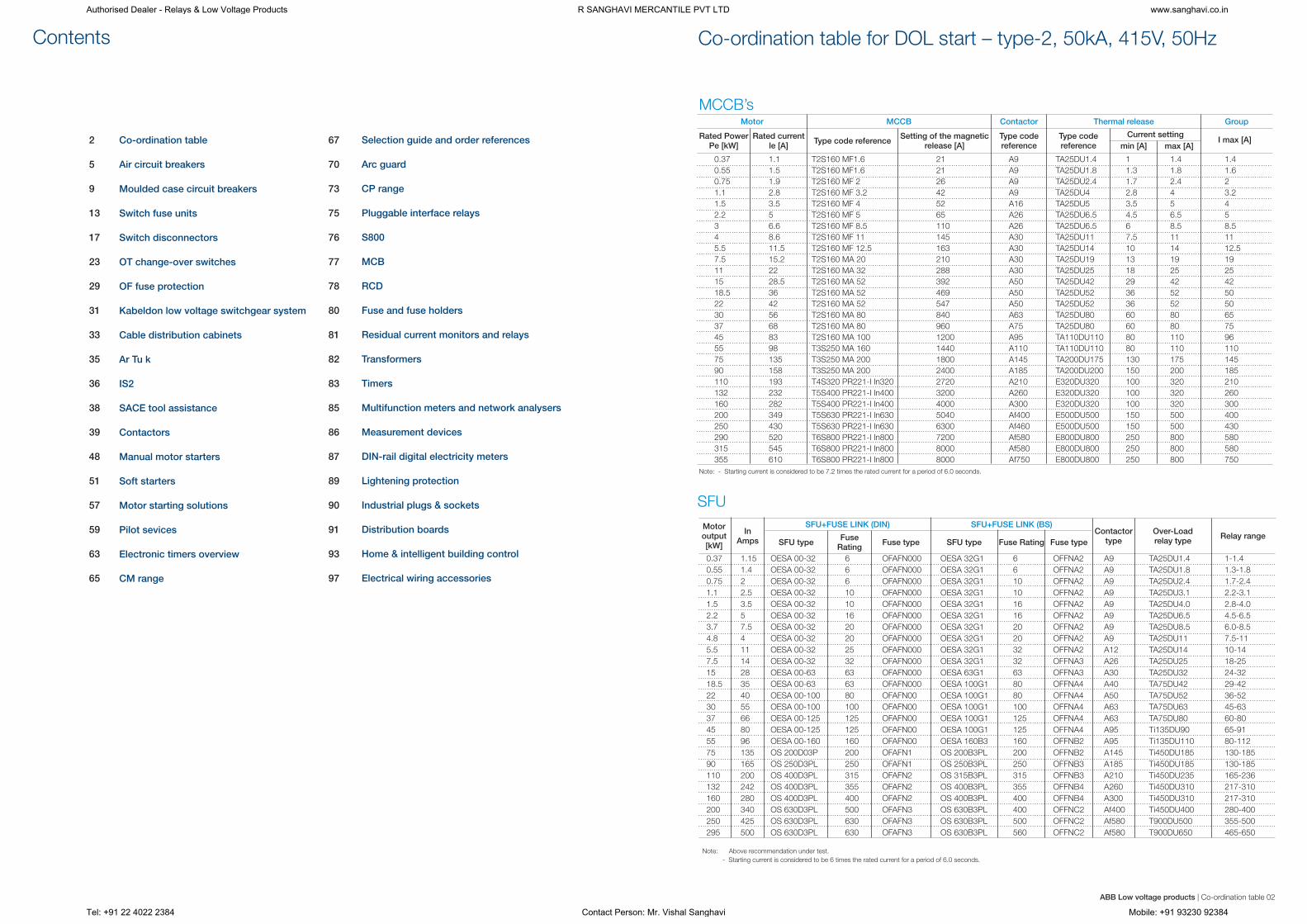
Co-ordination table for DOL start – type-2, 50kA, 415V, 50HzContents
Co-ordination table
Air circuit breakers
Moulded case circuit breakers
Switch fuse units
Switch disconnectors
OT change-over switches
OF fuse protection
Kabeldon low voltage switchgear system
Ar Tu k
SACE tool assistance
Contactors
Manual motor starters
Soft starters
Motor starting solutions
Pilot sevices
Electronic timers overview
CM range
Cable distribution cabinets
IS2
Selection guide and order references
Arc guard
CP range
Pluggable interface relays
S800
MCB
RCD
Fuse and fuse holders
Residual current monitors and relays
Transformers
Timers
Multifunction meters and network analysers
Measurement devices
DIN-rail digital electricity meters
Lightening protection
Industrial plugs & sockets
Distribution boards
Home & intelligent building control
Electrical wiring accessories
2
5
9
13
17
23
29
31
33
35
36
38
39
48
51
57
59
63
65
67
70
73
75
76
77
78
80
81
82
83
85
86
87
89
90
91
93
97
MCCB’s
SFU
Note: - Starting current is considered to be 7.2 times the rated current for a period of 6.0 seconds.
Note: Above recommendation under test.
- Starting current is considered to be 6 times the rated current for a period of 6.0 seconds.
0.37 1.1 T2S160 MF1.6 21 A9 TA25DU1.4 1 1.4 1.4
0.55 1.5 T2S160 MF1.6 21 A9 TA25DU1.8 1.3 1.8 1.6
0.75 1.9 T2S160 MF 2 26 A9 TA25DU2.4 1.7 2.4 2
1.1 2.8 T2S160 MF 3.2 42 A9 TA25DU4 2.8 4 3.2
1.5 3.5 T2S160 MF 4 52 A16 TA25DU5 3.5 5 4
2.2 5 T2S160 MF 5 65 A26 TA25DU6.5 4.5 6.5 5
3 6.6 T2S160 MF 8.5 110 A26 TA25DU6.5 6 8.5 8.5
4 8.6 T2S160 MF 11 145 A30 TA25DU11 7.5 11 11
5.5 11.5 T2S160 MF 12.5 163 A30 TA25DU14 10 14 12.5
7.5 15.2 T2S160 MA 20 210 A30 TA25DU19 13 19 19
11 22 T2S160 MA 32 288 A30 TA25DU25 18 25 25
15 28.5 T2S160 MA 52 392 A50 TA25DU42 29 42 42
18.5 36 T2S160 MA 52 469 A50 TA25DU52 36 52 50
22 42 T2S160 MA 52 547 A50 TA25DU52 36 52 50
30 56 T2S160 MA 80 840 A63 TA25DU80 60 80 65
37 68 T2S160 MA 80 960 A75 TA25DU80 60 80 75
45 83 T2S160 MA 100 1200 A95 TA110DU110 80 110 96
55 98 T3S250 MA 160 1440 A110 TA110DU110 80 110 110
75 135 T3S250 MA 200 1800 A145 TA200DU175 130 175 145
90 158 T3S250 MA 200 2400 A185 TA200DU200 150 200 185
110 193 T4S320 PR221-I In320 2720 A210 E320DU320 100 320 210
132 232 T5S400 PR221-I In400 3200 A260 E320DU320 100 320 260
160 282 T5S400 PR221-I In400 4000 A300 E320DU320 100 320 300
200 349 T5S630 PR221-I In630 5040 Af400 E500DU500 150 500 400
250 430 T5S630 PR221-I In630 6300 Af460 E500DU500 150 500 430
290 520 T6S800 PR221-I In800 7200 Af580 E800DU800 250 800 580
315 545 T6S800 PR221-I In800 8000 Af580 E800DU800 250 800 580
355 610 T6S800 PR221-I In800 8000 Af750 E800DU800 250 800 750
Rated PowerPe [kW]
Rated currentle [A]
Type code referenceType code reference
Type code reference
Current setting
min [A] max [A]I max [A]Setting of the magnetic
release [A]
Motor output [kW]
In Amps SFU type SFU type
SFU+FUSE LINK (DIN) SFU+FUSE LINK (BS)
Fuse Rating
Fuse RatingFuse type Fuse type
Contactor type
Over-Load relay type
Relay range
Motor MCCB Contactor Thermal release Group
ABB Low voltage products | Co-ordination table 02
Authorised Dealer - Relays & Low Voltage Products R SANGHAVI MERCANTILE PVT LTD www.sanghavi.co.in
Tel: +91 22 4022 2384 Contact Person: Mr. Vishal Sanghavi Mobile: +91 93230 92384

0.06 0.2 MS132-0,25 0,16 - 0,25 2.44 A9 0.25
0.09 0.3 MS132-0,40 0,25 - 0,40 3.9 A9 0.40
0.12 0.44 MS132-0,63 0,40 - 0,63 6.14 A9 0.63
0.18 0.6 MS132-0,63 0,40 - 0,63 6.14 A9 0.63
0.25 0.85 MS132-1,0 0,63 - 1,00 11.5 A9 1.0
0.37 1.1 MS132-1,6 1,00 - 1,60 18.4 A9 1.6
0.55 1.5 MS132-1,6 1,00 - 1,60 18.4 A9 1.6
0.75 1.9 MS132-2,5 1,60 - 2,50 28.75 A9 2.5
1.1 2.7 MS132-4,0 2,50 - 4,00 50 A16 4.0
1.5 3.6 MS132-4,0 2,50 - 4,00 50 A16 4.0
2.2 4.9 MS132-6,3 4,00 - 6,30 78.75 A26 6.3
3 6.5 MS132-10 6,30 - 10,0 150 A26 10.0
4 8.5 MS132-10 6,30 - 10,0 150 A26 10.0
5.5 11.5 MS132-12 8,0 - 12,0 180 A26 12
7.5 15.5 MS132-16 10,0 - 16,0 240 A30 16
11 22 MS132-25 20,0 - 25,0 375 A30 25
15 29 MS132-32 25,0 - 32,0 480 A30 32
18.5 35 MS450-40 28,0 - 40,0 480 A40 38
20 40 MS450-45,0 36,0-45,0 540 A63 47.5
22 44 MS450-50,0 40,0-50,0 600 A63 47.5
25 50 MS495-63,0 45,0-63,0 756 A75 60
30 60 MS495-63,0 45,0-63,0 756 A75 60
37 72 MS495-75,0 57,0-75,0 900 A75 72.5
40 79 MS495-90,0 70,0-90,0 1080 A95 85
45 85 MS495-90,0 70,0-90,0 1080 A95 85
51 94 MS495-100 80,0-100 1200 A95 96
Co-ordination table for DOL start – type-2, 50kA, 415V, 50Hz
Direct-on-line starter normal with manual motor controller
400V, 50kA, 50/60Hz, AC3, EN/IEC 60947-4-1, type 2
Motor Manual Motor Controller Contactor Max
Rated output[kW]
Current settingrange
[A]
Magnetic tripcurrent
[A]
allowed settingcurrent
[A]
Rated current[A]
Type Type
Direct-on-line starter normal start with manual motor starterTable number:400/415V ,50kA,50/60Hz, AC-3,EN/IEC 60947-4-1, type 2
MC4050NS2.2
MPCB - magnetic only
Motor Miniature Circuit Breaker Contactor Overload Relay Max
Rated output[kW]
Rated current
[A]Type
Intantaneous tripping
current [A]Type Type
Current setting range
[A]
Trip class[kW]
allowed setting
current [A]
0.06 0.22 MO325-0,25 2.44 A9 TA25DU0,25 0,16 - 0,25 10 0,25
0.09 0.34 MO325-0,40 3.9 A9 TA25DU0,40 0,25 - 0,40 10 0,4
0.12 0.44 MO325-0,63 6.14 A9 TA25DU0,63 0,40 - 0,63 10 0,63
0.18 0.72 MO325-1,00 11.5 A9 TA25DU1,00 0,63 - 1,00 10 1
0.25 0.83 MO325-1,00 11.5 A9 TA25DU1,00 0,63 - 1,00 10 1
0.37 1.12 MO325-1,60 16 A9 TA25DU1,40 1,00 - 1,40 10 1,35
0.55 1.45 MO325-1,60 16 A9 TA25DU1,80 1,30 - 1,80 10 1,75
0.75 1.9 MO325-2,50 27.5 A9 TA25DU2,40 1,70 - 2,40 10 2,35
1.1 2.59 MO325-4,00 40 A9 TA25DU3,10 2,30 - 3,10 10 2,95
1.5 3.45 MO325-4,00 40 A12 TA25DU4,00 2,80 - 4,00 10 3,75
2 4 MO325-6,30 78.75 A12 TA25DU5,00 3,50 - 5,00 10 4,75
2.2 4.8 MO325-6,30 78.75 A12 TA25DU6,50 4,50 - 6,50 10 6,25
3 6.48 MO325-9,00 135 A26 TA25DU8,50 6,00 - 8,50 10 8
4 8.6 MO325-9,00 135 A26 TA25DU11,0 7,50 - 11,0 10 10,5
5.5 11.1 MO325-12,5 187.5 A26 TA25DU14,0 10,0 - 14,0 10 13,5
7.5 14.8 MO325-16,0 240 A26 TA25DU19,00 13,0 - 19,0 10 16
9 18.3 MO325-20,0 300 A26 TA25DU19,00 13,0 - 19,0 10 18,5
11 21.5 MO325-25,0 375 A30 TA25DU25,0 18,0 - 25,0 10 23,5
15 30 MO450-32,0 416 A30 TA25DU32,0 22,0 - 32,0 10 30,5
18.5 37 MO450-40,0 520 A50 TA75DU42,0 29,0 - 42,0 10 39
22 45 MO450-50,0 650 A50 TA75DU52,0 36,0 - 52,0 10 48,5
30 60 MO495-63,0 819 A63 TA75DU63,0 45,0 - 63,0 10 61,5
37 72 MO495-75,0 975 A75 TA75DU80,0 60,0 - 80,0 10 72,5
40 79 MO495-90,0 1170 A95 TA110DU90 65,0 - 90,0 10 85
45 83 MO495-90,0 1170 A95 TA110DU90 65,0 - 90,0 10 85
51 94 MO495-100 1235 A110 TA110DU110 80,0 - 110 10 95
45 83 MO495-90,0 1170 A95 TA110DU90 65,0 - 90,0 10 85
51 94 MO495-100 1235 A110 TA110DU110 80,0 - 110 10 95
ABB Low voltage products | Co-ordination table 0403 | ABB Low voltage productsCo-ordination table
Authorised Dealer - Relays & Low Voltage Products R SANGHAVI MERCANTILE PVT LTD www.sanghavi.co.in
Tel: +91 22 4022 2384 Contact Person: Mr. Vishal Sanghavi Mobile: +91 93230 92384

05 Air circuit breaker | ABB Low voltage products ABB Low voltage products | Air circuit breaker 06
Authorised Dealer - Relays & Low Voltage Products R SANGHAVI MERCANTILE PVT LTD www.sanghavi.co.in
Tel: +91 22 4022 2384 Contact Person: Mr. Vishal Sanghavi Mobile: +91 93230 92384

Electronic releases general characteristics
The overcurrent protection for AC installations uses three types of
electronic release series:
PR121, PR122 and PR123.
The basic series, Pr121, offers the whole set of standard
protection functions, complete with a user-friendly interface.
It allows discrimination of which fault caused the trip by means of
the new led indications.PR122 and PR123 releases are of new
concept modular architecture. It is now possible to have a
complete series of protections, accurate measurements,signalling
or dialogue functions, designed and customisable for all
application requirements.
General specifications of the electronic releases include:
- operation without the need for an external power supply
- microprocessor technology
- high precision
- sensitivity to the true R.M.S. value of the current
- trip cause indication and trip data recording
- interchangeability among all types of releases
- setting for neutral configurable:
- OFF-50%-100%-200% of phase setting for circuit-breakers
E1, E2, E3 and E4/f, E6/f full-size versions, and E4-E6 with
external neutral protection;
- OFF-50% for standard E4 and E6.
The main performance features of the releases are listed below.
The protection system is made up of:
- 3 or 4 new generation current sensors (Rogowsky coil);
external current sensors (i.e. for external neutral, residual
current or source ground return protection);
- a protection unit selected among PR121/P, PR122/P or
PR123/P with optional communication module via Modbus or
Fieldbus plug network (PR122/P and PR123/P only), as well as
via a wireless connection;
- an opening solenoid, which acts directly on the circuit-breaker
operating mechanism (supplied with the protection unit).
07 Electronics releases | ABB Low voltage products ABB Low voltage products | Electronics releases 08
Authorised Dealer - Relays & Low Voltage Products R SANGHAVI MERCANTILE PVT LTD www.sanghavi.co.in
Tel: +91 22 4022 2384 Contact Person: Mr. Vishal Sanghavi Mobile: +91 93230 92384

09 Moulded case circuit breaker | ABB Low voltage products ABB Low voltage products | Moulded case circuit breaker 10
(MF up to In 12.5 A)
[KV]
Authorised Dealer - Relays & Low Voltage Products R SANGHAVI MERCANTILE PVT LTD www.sanghavi.co.in
Tel: +91 22 4022 2384 Contact Person: Mr. Vishal Sanghavi Mobile: +91 93230 92384

Moulded case circuit breakers
SACE Tmax
Moulded Case Circuit Breakers
Various application needs are met by the fixed version through
mounting the
conversion kit.
The following are available:
- Kit for conversion from fixed circuit-breaker to moving part of a
plug-in or withdrawable circuit-breaker
- Conversion kit for the connection terminals which make it
possible to obtain front and rear terminals for copper or
aluminium cables, and front and rear terminals for flat bar
terminals.
Accessories
1 Breaking Unit
2 Trip Units
3 Front
4 Shunt opening release - SOR and P-SOR
5 Under voltage release - UVR
6 Auxiliary contacts - AUX and AUX-E
7 Terminal covers
8 Front for lever operationg machanism - FLD
9 Direct rotary handle - RHD
10 Stored energy motor operator - MOE
11 Key lock - KLF
12 Early auxilliary contact - AUE
13 Transmitted rotary handle - RHE
14 Front terminal for copper cable - FC Cu
15 Front extended terminal - EF
16 Multi-cable terminal (only for T4) - MC
17 Front terminal for copper - aluminium - FC CuAl
18 Front extended spread terminal - ES
19 Rear oriented terminal - R
20 Conversion kit for plug-in/withdrawable versions
21 Guide of fixed part in withdrawable version
22 Fixed part - FP
23 Auxilliary position contact - AUP
24 Phase separator
25 PR010T
26 TT1
27 Racking out crank handle
28 Residual current release
11 Moulded case circuit breaker | ABB Low voltage products ABB Low voltage products | Moulded case circuit breaker 12
Authorised Dealer - Relays & Low Voltage Products R SANGHAVI MERCANTILE PVT LTD www.sanghavi.co.in
Tel: +91 22 4022 2384 Contact Person: Mr. Vishal Sanghavi Mobile: +91 93230 92384

Switch size A 32 63
Rated insulation voltage and rated Pollution degree 3 V 750 750
Dielectric strength 50 Hz, 1 min kV 8 8
Rated impulse withstand voltage kV 12 120Rated thermal current in ambient 40 C In open air A / W 32/7.5 63/7.5
max. fuse power dissipation (1) In enclosure A / W 32/7.5 63.75
In enclosure with solid links A 40 75
... with minimum cable cross section Cu mm2 6 16
Rated operational voltage AC-20 and DC-20 V 750 750
Rated operational current, AC-21A up to 500 V A 32 63
690 V A – 63(2)
Rated operational current, AC-22A up to 500 V A 32 63
690 V A – 63(2)
Rated operational current, AC-23A up to 500 V A 32 63(2)
690 V A – 40(2)
Rated conditional short-circuit current r.m.s. 80 kA, 415 V kA 10 12
and corresponding max. allowed cut-off current, peak values 100 kA, 500 V kA 6 9
- The cut-off currents refer to single phase fuse tests 50 kA, 690 V kA – 8
- Fuse selection tables on request
Rated short-time withstand current, 1s R.M.S. -value kA 1.5 2
Rated capacitor power 400 V kVAr 15 30
- The capacitor rating of the switch-fuse is limited by the fuse link 415 V kVAr 16 32
690 V kVAr – 50
Power loss / pole With rated current, without fuse W 0.7 4
Mechanical endurance Divide by two for operation cycles Oper. 20 000 20 000
Fuse types, IEC 269-2 Din 43620 00 00
NFC – 14x51
BS 88 A2-A3 A2-A3 A2-A4
-size/distance of fuse link bolts mm M5/73 75/73
Weight without accessories 3-pole switch fuses kg 1.6 1.6
4-pole switch fuses kg 1.9 1.9
Built-in terminal size Cu mm2 2.5 ... 25 2.5 ... 25
Terminal bolt size Metric thread diameter x length mm
Terminal tightening torque Counter torque required Nm 5 5
Fuse-links bolts tightening torque Nm 3.5 3.5
Operating torque Typical for 3-pole switch fuses Nm 3 3
OESA
Standard handles
IP 54 YASDB 51
– 32 A ... 160 A, suitable for 6 mm square shaft door interlock Black 1 - 0
defeatable
– Door drilling f 45 mm,
for OETLZX 74 door drilling f 18 mm
– door interlock in ON-position
– Padlockable with 3 padlocks in OFF-position
– Handle kits for side operated switch fuses include a shaft
Note: Special handles available against request. Contact our nearest sales office
YASDB 10
Black 1 - 0
Standard shaft / Shaft length OESAZS 25 / 210
Detachable neutral link / Thermal current / Max. cable cross section OESAZX 87 / 63A / 16 mm2 Cu
Change-over attachment kit / Shaft distance (incl. a handle with I-O-II indication) OESAZW 1 / 90mm (3) Mechanical interlock kit / Shaft distance –
(4)Electrical interlock –
Tunnel terminal sets for Cu-cables / Cable cross section (6 pcs / package) not required
Terminal clamps for AI or Cu-cables / Cable cross section (3 pcs / package) not required
mm
ESAZX 86 / 160A / 240 mm2 Cu
+ (0...10) x 15 mm
OZXA 5 / 1.5...35 mm2 Cu –
OZXB 2L / 25...120 mm2 AI/Cu OZXB 2L, OZXB 3/95...185mm2 AI/Cu
Remarks:
- Ambient temperature 600C: derating 20%. Mounting on
“ceiling”: derating 10%. Mounting on wall, horizontal
fuses: derating 8%.
- Utilization category B.
- The interlock attachment prevents one switch from closing to ON-
position, if the other is not in OFF-position.
- Closed circuit principal, for interlocking the switch movement. When
the coil circuit is dead, A-types cannot be operated to ON-position
and L- types to ON- or OFFposition. Coil voltages: 110V AC, 220V
AC, 24V DC, 48V DC, 60V DC, 110V DC, 220V Dc.
Approvals:
KEMA SEMKO
ASTA NEMKO
UL-Listed, UL-Recognized DEMKO
Canadian Standards Association Lloyds Register of Shipping
SETI Germanischer Lloyd
SEV USSR Register of Shipping
Detailed list on request
Comply with standards:
IEC 60947-3
IEC 408
BS 5419
VDE 0660, 0113
UL 98, UL 508
CSA C22.2 No 4 and 14
SS 4280605
KY 119-79/SETI
Tropical conditions:
Suitable for the following climate types:
– Warm damp IEC 721-2-1- and DIN 50019 041, 50019 042
– Extremely warm dry IEC 721-2-1- and DIN 50019 033,
50019 034 (consult derating)
13 Switch fuse units | ABB Low voltage products ABB Low voltage products | Switch fuse units 14
Switch fuses OESA 32-160 Switch fuses OESA 32-160
Technical data according to IEC 60947
125 160
750 750
8 8
12 12
125/12 160/12
125/12 135/9
125 160
50 50
750 750
125 160
125(2) 160(2)
125 160
125(2) 135(2)
125 160
50(2) 50(2)
23 23
17 17
14 14
5 5
50 57
55 62
90 100
5 9
20 000 20 000
00 00
22x58 –
A2-A4 B1-B2
M5/73, M8/94 M8/111
1.8 1.8
2.3 2.3
M8x25 M8x25
15...22 15.22
M5:3.5 / M8:10 10
5 5
100
750
8
12
100/12
100/12
100
50
750
100
100
100
100
100
50
23
17
14
5
45
47
80
4.5
20 000
00
–
A2-A4
M5/73,M8/94
1.8
2.3
M8x25
15..22
M5:3.5/M8:10
5
OESA
Authorised Dealer - Relays & Low Voltage Products R SANGHAVI MERCANTILE PVT LTD www.sanghavi.co.in
Tel: +91 22 4022 2384 Contact Person: Mr. Vishal Sanghavi Mobile: +91 93230 92384
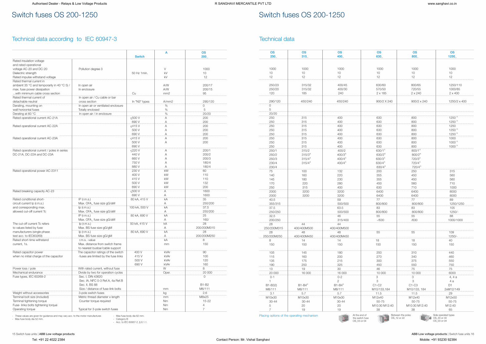
Technical data according to IEC 60947-3 Technical data
Rated insulation voltage
and rated operational
voltage AC-20 and DC-20 Pollution degree 3 V 1000
Dielectric strength 50 Hz 1min. kV 10
Rated impulse withstand voltage kV 12
Rated thermal current in
ambient 35 °C and temporarily in 40 °C 5) / In open air A/W 200/17
max. fuse power dissipation In enclosure A/W 200/15
...with minimum cable cross section Cu mm2 95
Rated thermal current of In open air / Cu cable or bar
detachable neutral cross section In "N3" types A/mm2 290/120
Derating, mounting on In open air or ventilated enclosure % 0
wall horizontal fuses Totally enclosed % 5
Derating at 60 °C In open air / in enclosure % 20/20
Rated operational current AC-21A A 200
A 200
Rated operational current AC-22A A 200
A 200
A 200
Rated operational current AC-23A A 200
A 200
Rated operational current / poles in series A 200/1
DC-21A, DC-22A and DC-23A A 200/2
A 200/3
A 180/4
A 180/4
Rated operational power AC-2311 kW 60
kW 110
kW 110
kW 132
kW 200
Rated breaking capacity AC-23 A 1600
A 1600
Rated conditional short- IP (r.m.s.) 80 kA, 415 V kA 35
circuit current Ip (r.m.s.) Max. OFA_ fuse size gG/aM A 250/200
and corresponding max. Ip (r.m.s.) 100 kA, 500 V kA 37.5
allowed cut-off current Tc Max. OFA_ fuse size gG/aM A 250/200
IP (r.m.s.) 80 kA, 690 V kA 25
Max. OFA_ fuse size gG/aM A 160/
The cut-off current Tc refers Ip (r.m.s.) 50 kA, 415 V kA 28
to values listed by fuse Max. BS fuse size gG/gM A 200/200M315
manufacturers (single phase Ip (r.m.s.) 80 kA, 690 V kA 28
test acc. to IEC60269) Max. BS fuse size gG/gM A 200/200M250
Rated short-time withstand r.m.s. -value kA 8
current, 1s. Max. distance from switch frame mm 150
to nearest busbar/cable support
Rated capacitor power The capacitor ratings of the switch 400 V kVAr 90
when no initial charge of the capacitor -fuses are limited by the fuse links 415 V kVAr 100
500 V kVAr 120
690 V kVAr 160
Power loss / pole With rated current, without fuse W 8
Mechanical endurance Divide by two for operation cycles Oper. 20 000
Fuse types, IEC 60269-2 Sec. I, DIN 43620 0
Sec. IA, NFC 0-3 Ref.A, 4a Ref.B
Sec. II, BS 88 B1-B2
Size / distance of fuse-link bolts mm M6/111
Weight without accessories 3-pole switch fuses kg 2.6
Terminal bolt size (included) Metric thread diameter x length mm M8x25
Terminal tightening torque Counter torque required Nm 15-22
Fuse- links bolts tightening torque Nm 4
Operating torque Typical for 3-pole switch fuses Nm 7
<500 V
690 V
<415 V
500 V
690 V
<415 V
500 V
690 V
<220 V
440 V
660 V
750 V
880 V
230 V
400 V
415 V
500 V
690 V
<500 V
690 V
A OS
Switch 200_
1000 1000 1000 1000 1000 1000
10 10 10 10 10 10
12 12 12 12 12 12
250/23 315/32 400/45 630/60 800/65 1250/110
250/20 315/32 400/30 570/50 720/55 1000/85
120 185 240 2 x 185 2 x 240 2 x 400
290/120 450/240 450/240 900/2 X 240 900/2 x 240 1250/2 x 400
0
5
20/204) 250 315 400 630 800 1250 4) 250 315 400 630 800 1250
250 315 400 630 800 12504) 250 315 400 630 800 1250 4) 250 315 400 630 800 1250
250 315 400 630 800 10004) 250 315 400 630 800 1000 4) 250 315 400 630 800 1000
4) 4) 250/1 315/2 400/2 630/1 800/14) 4) 4) 4) 250/2 315/3 400/3 630/2 800/24) 4) 4) 4) 250/3 315/4 400/4 630/3 720/3 4) 4) 4) 4) 230/4 315/4 400/4 630/4 720/4
4) 4) 230/4 630/4 720/4
75 100 132 200 250 315
140 160 220 355 450 560
145 180 230 355 450 560
170 220 280 450 560 710
250 315 400 630 710 1000
2000 3200 3200 6400 6400 8000
2000 3200 3200 6400 6400 8000
40.5 59 77 77 89
355/315 500/500 800/800 800/800 1250/1250
37.5 63.5 83 83 105
250/250 500/500 800/800 800/800 1250/-
32.5 46 55 55 88
200/250 315/400 -/630 /630 1000/1000
28 44 44
250/200M315 400/400M500 400/400M500
28 48 48 55 55 109
250/200M250 400/400M450 400/400M450 1250/-
8 14 14 18 18 40
150 150 150 150 150 150
105 145 180 250 310 440
115 160 200 270 340 460
135 175 215 300 375 550
190 250 325 450 550 750
13 19 30 46 75 75
20 000 16 000 16 000 10 000 10 000 6000
0-1 0-2 3 3 4, 4 a
1 2 3 3 4 a3) 3) B1-B32) B1-B4 B1-B4 C1-C2 C1-C3 D1
M8/111 M8/111 M8/111 M10/133,184 M10/133, 184 2xM12/149
3.1 5.7 5.7 11.5 11.5 29
M10x30 M10x30 M10x30 M12x40 M12x40 M12x50
30-44 30-44 30-44 50-75 50-75 50-75
5 20 20 M10:30 M12:40 M10:30 M12:40 M12:40
7 19 19 38 38 65
OS OS OS OS OS OS
250_ 315_ 400_ 630_ 800_ 1250_
I
OTest
I
OTest
NO
I
O
OF
F
At the end ofthe switch fuseOS_03 or 04
Placing options of the operating mechanism
I
OTest
I
OTest
NOI
O
OF
F
Between the polesOS_12 or 22 Te
st
I
O
Side operated typesOS_30 or 40OS_03 or 04
Switch fuses OS 200-1250 Switch fuses OS 200-1250
- These values are given for guidance and may vary acc. to the motor manufacturer.
- Max fuse body dia 52 mm.
- Max fuse body dia 62 mm.
- Category B
- Acc. to IEC 60957-2, § 6.1.1.
15 Switch fuse units | ABB Low voltage products ABB Low voltage products | Switch fuse units 16
-
-
-
-
-
Authorised Dealer - Relays & Low Voltage Products R SANGHAVI MERCANTILE PVT LTD www.sanghavi.co.in
Tel: +91 22 4022 2384 Contact Person: Mr. Vishal Sanghavi Mobile: +91 93230 92384

Technical data Technical data
Switch-disconnectors OT 16...160 Switch-disconnectors OT 16...160
- Below 48 V, two poles in parallel up to OT 80 are recommended particularly in polluted atmosphere
- 200A/min. 95 mm2, use busbar connections OEZXX6/13 or OZXT2
- Acc. to IEC 60947-1, § 6.1.1.
17 | ABB Low voltage productsSwitch disconnectors ABB Low voltage products | Switch 18disconnectors
Power loss / pole At rated operational current W 0.3 0.6 1.6 2.8 4.5 4.0 6.3 6.5
Mechanical endurance Divide by two for operation cycles Oper. 20000 20000 20000 20000 20000 20000 20000 20000
Weight without accessories 3-pole kg 0.11 0.11 0.11 0.27 0.27 0.36 0.36 1.1
4-pole kg 0.15 0.15 0.15 0.35 0.35 0.50 0.50 1.3
V 750 750 750 750 750 750 750 750
50 Hz 1min kV 6 6 6 6 6 6 6 10
kV 8 8 8 8 8 8 8 12
In open ai A 25 32 40 63 80 115 125 200
In enclosure A 25 32 40 63 80 115 125 160
In enclosure A 20 25 32 50 63 80 100 1252 Cu mm 4 6 10 16 25 35 50 70
2up to 415 V A 16 25 40 63 80 100 125 200)440 - 690 V A 16 25 40 63 80 100 125 160
up to 415 V A 16 20 23 45 75 80 90 135
440 V A 16 20 23 45 65 65 78 125
550 V A 16 20 23 45 58 60 70 125
690 V A 10 11 12 20 20 40 50 801)up to 48 V A 16/1 25/1 32/1 63/1 80/1 100/1 125/1 160/1
110 V A 16/2 25/2 32/2 63/2 80/2 100/2 125/2 160/1
220 V A 16/3 25/3 32/3 63/4 80/4 100/4 125/4 160/2
440 V A 16/4 16/4 16/4 16/4 16/4 160/3
500 V A 16/4 16/4 16/4 16/4 16/4 125/3
750 V A 16/8 25/8 32/8 160/41)up to 48 V A 16/1 25/1 32/1 63/1 80/1 100/1 125/1 160/1
110 V A 16/2 25/2 32/2 63/2 80/2 100/2 125/2 160/1
220 V A 16/4 25/4 32/4 45/4 45/4 63/4 63/4 160/2
440 V A 10/4 10/4 10/4 10/4 10/4 160/3
750 V A 16/8 16/8 16/8
220-240 V kW 3 4 5.5 11 22 22 22 45
400-415 V kW 7.5 9 11 22 37 37 45 75
440 V kW 7.5 9 11 22 37 37 45 75
500 V kW 7.5 9 11 22 37 37 45 75
690 V kW 7.5 9 11 15 18.5 37 45 75
up to 415 V A 128 160 184 350 640 640 720 1080
440 V A 128 160 184 360 448 520 624 1000
500 V A 128 160 184 360 448 480 580 1000
690 V A 80 88 96 160 160 320 400 640
up to 48 V A 64/1 100/1 128/1 180/1 252/1 400/1 500/1 640/1
110 V A 64/2 100/2 128/2 180/2 252/2 400/2 500/2 640/1
220 V A 64/3 100/4 128/4 180/4 180/4 252/4 252/4 640/2
440 V A 40/4 40/4 40/4 40/4 40/4 640/3
750 V A 64/8 64/8 64/8
50 kA kA 6.5 6.5 6.5 13 13 16.5 16.5
415 V A 40/32 40/32
100 kA kA 40/32 100/80 100/80 125/125 125/125
500 V A 17 17 30
10kA kA
690 V A 100/80 100/80 200/250
50 kA kA 4 4 8.2 8.2
690V A 25/16 25/16 125/100 125/100
690V, 0.25 s kA
690V, 1s kA 0.5 0.5 4 11 11 10 10 24
690V/500V kA 0.705 0.705 25/16 80/63 80/63 63/63 63/63 200/250
7
400 - 415 V kVAr 10 0.5 1 1.5 2.5 2.5 4
0.705 1.4 2.1 3.6 3.6 12
Rated insulation voltage and rated
operational voltage AC20/DC20 Pollution degree 3
Dielectric strength
Rated impulse withstand voltage
Rated thermal current and rated0 9)operational current AC20/DC20 ambient 4 C 0 9)ambient 4 C 0ambient 6 C
..with minimum conductor cross section
Rated operational current, AC-21A
Rated operational current, AC-23A
Rated operational current / poles in series, DC-21A
Rated operational current / poles in series, DC-23A
Rated operational power, AC-23A
(These values are given for guidance and
may vary acc. to the motor manufacturer)
Rated breaking capacity, AC-23A
Rated breaking capacity/poles in series, DC-23A
Rated conditional short-circuitpcurrent I (r.m.s.) and correspondin I (r.m.s.)p
cmax. al lowed cut-off current î Max. OFA_ fuse size gG/aM
I (r.m.s.)p
Max. OFA_ fuse size gG/aM
The cut-off current î refers to values I (r.m.s.)c p
listed by fuse manufacturers Max. OFA_ fuse size gG/aM
(single phase test acc. to IEC60269) I (r.m.s.)p
Max. OFA_ fuse size gG/aM
Rated short-time withstand current r.m.s. -value Icw
r.m.s. -value Icw
Rated short circuit making capacity Peak value Icm
Rated capacitor power
(The capacitor ratings are limited by the fuse link.)
SizeSwitch type
40OT40_
A16
OT16_63
OT63_25
OT25_80
OT80_100
OT100_125
OT125_160
OT160_
Authorised Dealer - Relays & Low Voltage Products R SANGHAVI MERCANTILE PVT LTD www.sanghavi.co.in
Tel: +91 22 4022 2384 Contact Person: Mr. Vishal Sanghavi Mobile: +91 93230 92384

Rated insulation voltage and
rated operational voltage AC-20, DC-20 Pollution degree 3 V
Dielectric strength 50 Hz 1min. kV
Rated impulse withstand voltage kV
Rated thermal current and rated
operational current AC-20, DC-204) in ambient 40 °C In open air A
In enclosure A
...with minimum cable cross section Cu mm2
Rated operational current, AC-21A = 500 V A
690 V A
1000 V A
Rated operational current, AC-22A = 500 V A
690 V A
1000 V A
Rated operational current, AC-23A = 500 V A
690 V A
1000 V A1)Rated operational current / poles in series, DC-21A...23A = 110 V A
220 V A
440 V A
660 V A
Rated operational current / poles in series, DC-21B 800 V A
1000 V A3)Rated operational power, AC-23 230 V kW
400 V kW
415 V kW
500 V kW
690 V kW
Rated breaking capacity in = 500 V A
category AC-23 690 V A
Rated conditional short-circuit I (r.m.s.) 100 kA, 500 V kAp
current I (r.m.s.) and Max. OFA_ fuse size gG/aM Ap
corresponding max. allowed
cut-off current îc
The cut-off current î refers to I (r.m.s.) 80 kA, 690 V kAc p
values listed by fuse Max. OFA_ fuse size gG/aM A
manufacturers (single phase
test acc. to IEC60269).
Rated short-time withstand current r.m.s. value I 690 V 0,15s kAcw
690 V 0,25s kA
690 V 1s kA
Rated short-time making capacity Peak value I 690 V kAcm
Power loss / pole With rated current W
Mechanical endurance Divide by two for oper. cycles Oper.
Weight without accessories 3-pole switch kg
Terminal bolt size Metric thread diameter x length mm
Terminal tightening torque Counter torque required Nm
Operating torque 3-pole switch disconnector Nm
Size A
Switch Type
200 250 315 400 630 800
OT200E_ OT250_ OT315_ OT400_ OT630_ OT800_
Technical data according to IEC 60947-3
- Further ratings on request
- Category B
- These values are given for guidance and may vary acc. to the motor manufacturer.
- Acc. to IEC 60947-1, § 6.1.1.
Placing options of the operating mechanism
At the end of switch fuse
OT_03 or 04Between the poles
OT_ 12 or 22
Side operated types
OT_ 30 or 40
OT_03 or 04
Technical data
1000 1000 1000 1000 1000 1000
10 10 10 10 10 10
12 12 12 12 12 12
200 250 315 400 630 800
200 250 315 400 630 800
95 120 185 240 2x185 2x240
200 250 315 400 630 800
200 250 315 400 630 800
200 250 315 400 630 800
200 250 315 400 630 800
200 250 315 400 630 800
200 250 315 400 630 800
200 250 315 400 630 800
200 250 315 400 630 800
135 135 200 200 400 4002) 2) 200/2 250/2 315/1 400/1 630/1 800/12) 2) 200/2 250/2 315/2 400/2 630/1 800/1
200/3 250/3 315/3 360/3 630/2 800/22) 2) 2) 200/4 230/4 315/4 360/4 630/4 650/4
200/5 250/5 315/5 400/5 600/5 600/5
200/6 250/6 315/6 400/6 600/6 600/6
60 75 100 132 200 250
110 140 160 220 355 450
110 145 180 230 355 450
132 170 220 280 400 560
200 250 315 400 630 800
1600 2000 2520 3200 5040 6400
1600 2000 2520 3200 5040 6400
40.5 40.5 61.5 61.5 90 90
315/315 315/315 500/450 500/450 800/1000 800/1000
40.5 40.5 59 59 83.5 83.5
355/315 355/315 500/500 500/500 800/1000 800/1000
15 15 31 31 38 38
15 15 24 24 36 36
8 8 15 15 20 20
30 30 65 65 80 80
4 6.5 6.5 10 25 40
20000 20000 16000 16000 10000 10000
1.2 1.2 2.2 2.2 5.2 5.2
M8x25 M8x25 M10x30 M10x30 M12x40 M12x40
15-22 15-22 30-44 30-44 50-75 50-75
7 7 16 16 27 27
Switch-disconnectors OT 200...800 Switch-disconnectors OT 200...800
19 | ABB Low voltage productsSwitch disconnectors ABB Low voltage products | 20Switch disconnectors
Authorised Dealer - Relays & Low Voltage Products R SANGHAVI MERCANTILE PVT LTD www.sanghavi.co.in
Tel: +91 22 4022 2384 Contact Person: Mr. Vishal Sanghavi Mobile: +91 93230 92384

Rated insulation voltage and
rated operational voltage AC20/DC20 Pollution degree 3 V
Dielectric strength 50 Hz 1min. kV
Rated impulse withstand voltage kV
Rated thermal current and0 9)rated operational current AC20/DC20 ambient 40 C In open air A0 9) ambient 40 C In enclosure A0 ambient 60 C In enclosure A
2..with minimum conductor cross section Cu mm
Rated operational current, AC-21A up to 690 V A
1000 V A
Rated operational current, AC-22A up to 500 V A
690 V A
Rated operational current, AC-23A up to 500 V A
690 V A
Rated operational current / poles in series, DC-21A up to 48 V A
110 V A
220 V A
Rated operational power, AC-23A 400-415 V kW
(These values are given for guidance and 440 V kW
may vary acc. to the motor manufacturer) 500 V kW
690 V kW
Rated breaking capacity, AC-23A up to 500 V A
690 V A
Rated conditional short-circuit I (r.m.s.) 80 kA kAp
current I (r.m.s.) and corresponding Max. OFA_ fuse size gG/aM = 415 V Ap
max. allowed cut-off current îc 100 kA kA
The cut-off current îc refers to values Max. OFA_ fuse size gG/aM = 500 V A
listed by fuse manufacturers I (r.m.s.) 50 kA kAp
(single phase test acc. to IEC60269) Max. OFA_ fuse size gG/aM = 690 V A
Rated short-time withstand current r.m.s. -value I 690 V 0.25s kAcw
690 V 1s kA
Rated short circuit making capacity Peak value I 415 V kAcm
500 V kA
690 V kA
Max. distance from switch frame to
nearest busbar/cable support mm
Power loss / pole At rated operational current W
Mechanical endurance Divide by two for operation cycles Oper.
Weight without accessories 3-pole kg
4-pole kg
Terminal bolt size Metric thread diameter x length mm
Terminal tightening torque Counter torque required Nm
Operating torque 3-pole switch-disconnector Nm
I (r.m.s.)p
1000 1000 1000 1000 1000 1000 1000 1000 1000 1000
10 10 10 10 10 10 8 10 10 8
12 12 12 12 12 12 8 12 12 8
1000 1000 1250 1250 1600 1600 1250 2000 2500 3150
1000 1000 1250 1250 1600 1600 1250 2600
1000 2300
2x300 2x300 2x400 2x400 2x500 2x500 2x(80x5) 3x500 4x500 3x(100x10)2)8) 2)8) 2) 6) 1000 1000 1250 1250 1600 1600 1250 2000 2500 3150
2) 1000 1000 1250 1250 1600 1600 1000 10002)8) 2)8) 2) 1000 1000 1250 1250 1600 1600 1250 2000 2500 1600
800 1000 1000 1250 1250 1600
800 1000 1000 1250 1000 1250
800 1000 800 1250 1000 1250 800
1250/1
1250/2
1250/3
450 560 560 710 560 710 400
500 630 630 800 630 800 400
560 710 710 900 710 900 450
800 1000 800 1200 800 1200
8000 10000 10000 10000 10000 10000 6400 64003) 4) 6400 10000 6400 10000 8000 10000 2500 4800
100 100 100 100 100 100 105 140
1250/1250 1250/1250 1250/1250 1250/1250 1250/1250 1250/1250
106 106 106 106 106 106 105 140
1250/1250 1250/1250 1250/1250 1250/1250 1250/1250 1250/1250
105 105
5) 50 50 50 50 50 50 56 80 805) 5) 50 50 50 50 50 50 50 55 55 80
1) 105 176
105 1407) 7) 7) 7) 7) 7) 110 110 110 110 110 110 105 176 176 105
150 150 150 150 150 150 150 150
19 19 29 29 48 48 40 55 85 140
6000 6000 6000 6000 6000 6000 6000 6000 6000 1200
14.1 14.1 14.1 14.1 1 5.2 15.2 16.3 22 22 37
18 18 18 18 19,5 19,5 20.5 28 28 47
M12x50 M12x50 M12x50 M12x50 M12x60 M12x60 M12x60 M12x60 M12x60 M12x60
50...75 50...75 50...75 50...75 50...75 50...75 50...75 50-75 50-75 50...75
65 65 65 65 65 65 24 65 65 50
Technical data according to IEC 60947-3
Size A
Switch Type
- Extended phase distance (185 mm)
- IEC 947-3, utilization category B, infrequent operation
- Pf. 0.95
- Pf. 0.65
- Maximum distance between busbar support and switch terminal 70 mm.
- 690 V: 2500 A
- The value is 92 kA for 4-pole switch-disconnectors.
- Up to 415 V
- Acc. to IEC60947-1, § 6.1.1.
Technical data
OT1000 OT1250 OT1600 OETL1250M OT2000_ OT2500 OETL3150_
E X E X E X
Switch-disconnectors OT 1000...2500 and OETL 3150 Switch-disconnectors OT 1000...2500 and OETL 3150
21 | ABB Low voltage productsSwitch disconnectors ABB Low voltage products | 22Switch disconnectors
Authorised Dealer - Relays & Low Voltage Products R SANGHAVI MERCANTILE PVT LTD www.sanghavi.co.in
Tel: +91 22 4022 2384 Contact Person: Mr. Vishal Sanghavi Mobile: +91 93230 92384

Rated insulation voltage and
operational voltage AC20/ DC20 Pollution degree 3 V 750
Dielectric strength 50 Hz 1min. kV 6
Rated impulse withstand voltage kV 8
Rated thermal current and rated operational / ambient 40°C In open air A 25
current AC20/DC20 / ambient 40°C In enclosure A 251
/ ambient 40°C In enclosure A 202...with minimum cable cross section In enclosure mm 20
Rated operational current, AC-21A up to 500 V A 16
690 V A 16
Rated operational current, AC-22A up to 500 V A 16
690 V A 16
Rated operational current, AC-23A up to 415 V A 16
440 V A 16
500 V A 16
690 V A 101) Rated operational power, AC-23A 230 V kW 3
The kW-ratings are accurate for 3-phase 1500 400 V kW 7.5
R.P.M. standard asychronous motors 415 V kW 7.5
500 V kW 7.5
690 V kW 7.5
Rated breaking capacity in up tp 415 V A 128
category AC-23 500 V A 128
690 V A 80
Rated conditional short-circuit I (r.m.s.)50 kA,415 V î (peak) kA 6.5p
current I (r.m.s.) and corresponding max. Max. OFA_ fuse size gG/aM A/A 40/32p
allowed cut-off current îc refer to value.
The cut-off current îc refers to values I (r.m.s.)100 kA500 V î (peak) kAp c
listed by fuse manufacturers Max. OFA_ fuse size gG/aM A
(single phase test acc. to IEC60269).
Rated short-time withstand current I (r.m.s.) 690 V1s kA 0.5cw
2)Rated short-time making capacity I (peak) 690 V kA 0.7cw
Power loss / pole With rated current W 0.33)Mechanical endurance Number of oper. cycles Cycles 10000
Mechanical endurance / switch Number of operations Oper. 200002Cable size Cu-wire size suitable for mm 0.75-10
termianal clamps AWG 18-8
Terminal tightening torque Counter torque required Nm 0.8
Operating torque Typical for 3-pole switches Nm 1
Weight without accessories 3-pole switch kg 0.25
4-pole switch kg 0.31
rated
c
750 750 750 750 750 750
6 6 6 6 6 6
8 8 8 8 8 8
32 40 63 80 115 125
32 40 63 80 115 125
25 32 50 63 80 100
6 10 16 25 35 50
25 40 63 80 100 125
25 40 63 80 100 125
25 40 63 80 100 125
25 40 63 80 100 125
20 23 45 75 80 90
20 23 45 65 65 78
20 23 45 58 60 70
11 12 20 20 40 50
4 5,5 11 22 22 22
9 11 22 37 37 45
9 11 22 37 37 45
9 11 22 37 37 45
9 11 15 18.5 37 45
160 184 360 640 640 720
160 184 360 464 480 560
88 96 160 160 320 400
6.5 6.5 13 13 16.5 16.5
40/32 40/32 100/80 100/80 125/125 125/125
17 17
100/80 100/80
0.5 0.5 1 1.5 2.5 2.5
0.7 0.7 1.4 2.1 3.6 3.6
0.6 1.6 2.8 4.5 4.0 6.3
10000 10000 10000 10000 10000 10000
20000 20000 20000 20000 20000 20000
0.75-10 0.75-10 1.5-35 1.5-35 10-70 10-70
18-8 18-8 14-4 14-4 8-00 8-00
0.8 0.8 2 2 6 6
1 1 1.2 1.2 2 2
0.25 0.25 0.64 0.64 0.90 0.90
0.31 0.31 0.70 0.70 1.18 1.18
Technical data according to IEC 60947-3
Switch Type OT16_
Technical data
OT25_ OT40_ OT63_ OT80_ OT100_ OT125_
OT manual change-over switches OT manual change-over switches
23 OT change-over switches | ABB Low voltage products ABB Low voltage products | 24OT change-over switches
Authorised Dealer - Relays & Low Voltage Products R SANGHAVI MERCANTILE PVT LTD www.sanghavi.co.in
Tel: +91 22 4022 2384 Contact Person: Mr. Vishal Sanghavi Mobile: +91 93230 92384

Class of equipment PC PC PC
Rated short-time withstand current I (r.m.s.) 690 V 0.1s kA 15 15 15
Rated operational current, AC-31B up to 415 V A 160 200 250
Rated operational current, AC-33B up to 415 V A 160 200 250
Size Size OT_160_ OT_200_ OT_250_ OT_315_ OT_400_ OT_630_ OT_800_ OT1000_ OT1250_ OT1600_ OT2000_ OT2500_
Rated insulation voltage and rated Pollution
operational voltage AC20/DC20 degree 3 V 1000 1000 1000
Dielectric strength 50 Hz 1min. kV 10 10 10
Rated impulse withstand voltage kV 12 12 12
Rated thermal current and rated operational / ambient 40°C In open air A 160 200 250
current AC20/DC20 / ambient 40°C In enclosure A 160 200 25022 ..with minimum conductor cross section Cu mm 70 95 120
Rated operational current, AC-21A up to 500 V A 160 200 250
690 V A 160 200 250
Rated operational current, AC-22A up to 500 V A 160 200 250
690 V A 160 200 250
Rated operational current, AC-23A up to 415 V A 160 200 250
440 V A 160 200 250
500 V A 160 200 250
690 V A 160 200 2501) Rated operational power, AC-23A 230 V kW 45 60 75
The kW-ratings are accurate for 3-phase 1500 400 V kW 90 110 140
R.P.M. standard asychronous motors 415 V kW 90 110 145
500 V kW 110 132 170
690 V kW 160 200 250
Rated breaking capacity in up to 415 V A 1280 1600 2000
category AC-23 500 V A 1280 1600 2000
690 V A 1280 1600 2000
Rated conditional short-circuit I (r.m.s.) 80 kA, 415 V I (peak) kA 40.5 40.5 40.5 p
current I (r.m.s.) and Max. OFA_ fuse size gG/aM A/A 355/315 355/315 355/315p
cut-off current I (peak) value. I (r.m.s.) 100 kA, 500 V I (peak) kA 40.5 40.5 40.5 c p c
The cut-off current I refers to values Max. OFA_ fuse size gG/aM A 315/315 315/315 315/315c
listed by fuse manufacturers I (r.m.s.) 80 kA, 690 V I (peak) kA 40.5 40.5 40.5p c
(single phase test acc. to IEC60269). Max. OFA_ fuse size gG/aM A 355/315 355/315 355/315
Rated short-time withstand current I (r.m.s.) 690 V 0.15s kA 15 15 15 cw
690 V 0.25s kA 15 15 15
690 V 1s kA 8 8 82) 3)Rated short-time making capacity I (peak) 690 V kA 30 30 30 cm
Power loss / pole With rated current W 2.4 4 6.54)Mechanical endurance Number of oper. cycles Cycles 8000 8000 8000
Mechanical endurance / switch Number of operations Oper. 16000 16000 16000
Terminal bolt size Metric thread
diameter x length mm M8x25 M8x25 M8x25
Terminal tightening torque Counter torque required Nm 15-22 15-22 15-22
Operating torque Typical for 3-pole
switches Nm 7 7 7
Weight without accessories 3-pole switch kg 2.5 2.5 2.5
4-pole switch kg 3.2 3.2 3.2
c
Technical data according to IEC 60947-3
Technical data according to IEC 60947-6-1
OT manual and motorized change-over switches
- These values are given for guidance and may vary acc. to the motor manufacturer.
- Short circuit duration >50ms, without fuse protection
- Max. distance from switch frame to nearest busbar / cable support 150 mm
- Operating cycle: O - I - O - II - O
- Category AC-21B, up to 415V
- For manual change-over switches.
- For motorized change-over switches.
1000 1000 1000 1000 1000 1000 1000 1000 1000
10 10 10 10 10 10 10 10 10
12 12 12 12 12 12 12 12 12
315 400 630 800 1000 1250 1600 2000 2500
315 400 630 800
185 240 2 x 185 2x240 2 x 300 2 x 400 2 x 500 3 x 500 4 x 500
315 400 630 800 1000 1250 1600 2000 5) 2500 5)
315 400 630 800 1000 1250 1600
315 400 630 800 1000 1250 1600
315 400 630 800 1000 1250 1600
315 400 630 800 1000 1250 1250
315 400 630 800 1000 1250 1250
315 400 630 800 1000 1250 1250
315 400 630 800 1000 1250 1250
100 132 200 250 315 400 400
160 220 355 450 560 710 710
180 230 355 450 560 710 710
220 280 400 560 710 900 900
315 400 630 800 1 000 1 250 1 250
2520 3200 5040 6400 10000 10000 10000
2520 3200 5040 6400 10000 10000 10000
2520 3200 5040 6400 10000 10000 10000
59 59 83.5 83.5 100 100 100
500/500 500/500 800/1000 800/1000 1 250/1250 1250/1250 1250/1250
61.5 61.5 90 90 106 106 106
500/450 500/450 800/800 800/800 1250/1250 1250/1250 1250/1250
59 59 83.5 83.5
500/500 500/500 800/1 000 800/1 000
31 31 38 38 50 50 50 50 50
24 24 36 36 50 50 50 50 50
15 15 20 20 50 50 50 50 50
65 65 80 80 92 92 92 110 110
6.5 10 25 40 19 29 48 55 85
8000 8000 5000 5000 3000 3000 3000 2000 2000
16000
16000 10000 10000 6000 6000 6000 4000 4000
M10x30 M10x30 M12x40 M12x40 M12x60 M12x60 M12x60 M12x60 M12x60
30-44 30-44 50-75 50-75 50-75 50-75 50-75 50-75 50-75
16 16 27 27 7 8 78 78 78 78
4.7 4.7 12.8 12.8 32.3 32.3 34.8 48 48
5.8 5.8 15.6 15.6 40.2 40.2 43.3 60 60
Technical data
OT manual and motorized change-over switches
25 | ABB Low voltage productsOT change-over switches ABB Low voltage products | 26OT change-over switches
PC PC PC PC PC PC PC PC PC
25 25 38 38 50 50 50 50 506)315 400 630 /650 800 /720 1 000 1 250 1 600 2000 20006) 7) 6) 7)315 400 630 /650 800 /650 1 000 1 000 1 000
7) 6) 7)
Authorised Dealer - Relays & Low Voltage Products R SANGHAVI MERCANTILE PVT LTD www.sanghavi.co.in
Tel: +91 22 4022 2384 Contact Person: Mr. Vishal Sanghavi Mobile: +91 93230 92384

Fully automatic solution Automatic transfer switches160 A to 800 A, OTM_C_D
1 Change-over switch
2 Automatic control unit (three types; OMD200, OMD300,
OMD800)
3 Motor operator
4 Switch panel, the operating mechanism
5 Handle for manual operation
6 Motor/Manual selection
7 Terminals for motor operator voltage supply
8 Terminals for locking state information
9 Fuse of motor operator
10 Locking latch for releasing the handle and locking electrical
control
11 Locking clip for locking manual operation
12 Voltage sensing wires
13 Place for auxiliary contact blocks
1) Dual power source allows the motor operator to be supplied by two separate voltage supplies.
This way the motor operator is always energized from the available line.
2) Consult us for more detailed information
3) OTM_C_2D and OTM_C_3D, the duration of switching and back-switching delay is the same, i.e. the time delay is same for I-II and II-I.
4) OTM_C_2D and OTM_C_3D, generator stop delay has two fi xed values, 5 sec or 10 min.
5) In case of source failure, the OMD controller unit can be supplied with an external auxiliary supply with 24…110 V DC.
x = included as standard
o = as an accessory
Our ATS range between 160 A and 800 A includes sophisticated
features in extremely compact footprint area without neglecting
features that makes assembly easy and safe, every time.
Safe and reliable
Easy installation
No more expensive repair work
ABB automatic transfer switches ensure service continuity with a
number of built-in, integrated safety features. The change-over
mechanism, for example, offers three stable positions which
ensure isolation of the two asynchronous power supplies. This
eliminates any risk of short-circuit between them, even in the
presence of transient voltages. The automatic transfer switch is
equipped with handle for manual operation in case of emergency
The design of ABB automatic transfer switch is advanced and
compact, allowing installation in confined spaces at considerable
savings. They are very easy to install: The automatic control unit
OMD_ can be adjusted according to the mounting depth of the
panel. Voltage sensing kit is installed at the factory thus reducing
the expensive and time consuming installation work.
The motor operator of the ATS is protected by a fuse. If the
operation frequency is exceeded, the fuse protects the motor,
thus saving it from expensive repair work.
27 Fully automatic solution | ABB Low voltage products ABB Low voltage products | Automatic transfer switches 28
OTM_C_D products overview
Manual operation with handle x x x
Local operation with front panel keypad x x x
Automatic transfer switching equipment (ATSE) x x x
Dual power source for the motor operator 1) o x o
Measurement
Three phase voltage measurement on LINE 1 x x x
Single phase voltage measurement on LINE 1 x x x
Three phase voltage measurement on LINE 2 x x x
Single phase voltage measurement on LINE 2 x x x
Frequency on LINE 1 x x x
Frequency on LINE 2 x x x
Possibility to check the measurements via LCD x
Configuration 2)
By DIP switches x x
By rotary switches x x
By keypad and LCD x
Voltage threshold setting x x x
Frequency threshold setting x
Time delays
Switching delay x 3) x 3) x
Dead band time I-II x
Back-switching delay x 3) x 3) x
Dead band time II-I x
Generator stop delay x 4) x 4) x
Line priority x
Features
Generator start and stop x x x
Off-load test sequence x x x
On-load test sequence x x x
Source status via front panel x x x
Switch position via front panel x x x
LCD x
Fieldbus interface x
Secondary load control x
Alarm log x
Auxiliary voltage supply 5) x
Applications
Transfer between two utilities x x x
Transfer between an utility and a genset x x x
OTM_C_2D OTM_C_3D OTM_C_8D
Authorised Dealer - Relays & Low Voltage Products R SANGHAVI MERCANTILE PVT LTD www.sanghavi.co.in
Tel: +91 22 4022 2384 Contact Person: Mr. Vishal Sanghavi Mobile: +91 93230 92384

2... 1250 A, 500 V
DIN-Type HRC fuse links (blade-type), 2...1250 A, 500 V
BS-Type HRC fuse links (bolted-type), 2...800 A, 500 V
OF fuse protection-safe and reliable OF fuse protection-safe and reliable
2...1250 A, 500 V
- Total safety for your cables, motors and electronics protection.
- Wide and dense current ratings for optimal dimensioning of other circuit components.
- Low let through energy, low cut off characteristics, reduced electro magnetic stress.
- Energy saving through low power losses.
- No deration required for connected equipment in normal situation.
- High breaking capacity 80 kA at 500 V (AC).
- Fault indication on the top of the fuse link.
- Conforms to the standards IS:13703 / IEC 60269.
- Available with ISI and CE marking.
29 | ABB Low voltage productsOF fuse protection ABB Low voltage products | 30OF fuse protection
Authorised Dealer - Relays & Low Voltage Products R SANGHAVI MERCANTILE PVT LTD www.sanghavi.co.in
Tel: +91 22 4022 2384 Contact Person: Mr. Vishal Sanghavi Mobile: +91 93230 92384

Kabeldon low voltage switchgear system Kabeldon IP-system
Kabeldon low-voltage distribution systems feature small
dimensions, flexibility, safety, reliability and clear layout.
The distribution board may be planned with the Connect IT
program, which is available free. It is a simple matter to wire up
the distribution board and put it into service. In indoor electrical
rooms, the busbar system can also be mounted on the wall.
However, we recommend an enclosed distribution board located
outside both for safety and to save valuable indoor space.
Among other things, the distribution boards satisfy the
requirements of:
IEC 60439 Low-voltage switchgear and controlgear assemblies
Part 1: Type-tested and partially type-tested assemblies.
Part 5: Particular requirements ”Assemblies for power distribution
in public network”.
For assemblies intended to be installed outdoors in public places
cable distribution cabinets (CDCs) for power distribution in
networks.
IEC 60947 Low-voltage switchgear and controlgear;
Part 1: General rules.
Part 3: Switches, disconnectors, switch-disconnectors
and fuse combination units.
Some typical applications for Kabeldon IP-system:
- Utilities
- electricity distribution in low voltage networks
- substations and cable distribution cabinets
- Roads
- street and road lighting; traffi c lights
- Railways
- electricity supply for railways, trams, underground trains
- Buildings
- distribution boards for hospitals, hotels,food shops, offices,
etc.
- Ports and airports
- electricity supply for boats and ships
- electricity supply for aircraft on the ground
- Sports installations
- floodlighting for football and sports stadiums
- lighting for jogging tracks, control panels for ski-lifts, etc.
- Construction sites
- temporary electricity supply
- central electric heating
- distribution boards for cranes and other equipment
- Temporary activities
- electricity supply for street markets, travelling
- exhibitions, circuses, fairgrounds, etc.
- Communication systems
- enclosures for fi bre-optic networks
- enclosures for antenna systems and cable TV
- terminal strips for telephony
- Industry/agriculture
- distribution boards to supply standby power to various
types of industrial firms
The system consists of a unique, touch-proof busbar system
which is combined with a broad range of switching devices and
connections.
Features of the Kabeldon IP-system are its simplicity and
reliability. These are the most important factors when you want to
achieve
low operating costs and high delivery reliability in a distribution
system.
- Busbars of continuously-extruded aluminium sections,
insulated
with a layer of polyamid.
- The busbar has a touch-proof contact slot. This ensures safety
regardless of where on the busbar the switching device will be
placed.
- Switching devices are available for both diazed and blade
fuses.
- The switching devices can be arranged in any order, regardless
of rated current
- All parts, busbars and devices, fulfi l IP2X protection in
accordance with IEC 60529*).
- Switching devices 100-1600 A.
- It is easy to add new switching devices to existing distribution
boards.
- Switching devices are mounted on and connected to the
busbar system in the same operation.
- Switching devices can be connected when the system is live.
- Always voltage-free (“dead”) when changing fuses.
- Busbars are available with rated currents from 400 to 1600 A.
- Switching devices, connectors and busbars combine to form a
modular system. Each module is 12.5 mm. The modular
system makes planning easier.
- The compact design of the switching devices makes them
suitable for use in many different types of distribution boards.
- All switching devices have a utilisation category so that they
can be used in cable distribution cabinets, substations and
other distribution boards.
31 | ABB Low voltage productsKabeldon low voltage switchgear system ABB Low voltage products | 32Kabeldon IP-system
Proven reliability, insulated and personal safeModern distribution technology
Authorised Dealer - Relays & Low Voltage Products R SANGHAVI MERCANTILE PVT LTD www.sanghavi.co.in
Tel: +91 22 4022 2384 Contact Person: Mr. Vishal Sanghavi Mobile: +91 93230 92384

Rugged, corrosion-resistant enclosures Reference pictures, electricity distribution
Since the 1930s we have been manufacturing cable distribution
cabinets.
The latest generation of cable distribution cabinets was developed
based on our long experience of systems for demanding
environments. At the same time, they satisfy current requirements
for long life with undiminished safety and low operating and
maintenance costs.
In Scandinavia, where snow is commonly cleared with
snowploughs and where the temperature in winter can drop to -
25 °C or lower, stability and surface treatment must be of the
highest class. Resistance to external impact tests with 150 Nm
according to standard IEC 60439-5.
In addition, good ventilation is essential to disperse heat during
the summer and to eliminate condensation
Enclosures
Enclosure series CDC and SDC are made of hot-dip galvanized
sheet steel and are built
to these standards:
ISO 1461, IEC 60439-1, IEC 60439-5.
Both CDC and SDC are developed in close collaboration with
users. The enclosures satisfy the demands of the network
companies and the contractors for simplicity and fl exibility. They
can also be used for broadband systems using fi bre-optic cables.
The degree of protection is IP34D.
Surface treatment
CDC and SDC enclosures are made of sheet steel and are
protected against corrosion by hot-dip galvanizing according to
ISO 1461. For parts that are buried in the ground, the corrosion
protection has been reinforced with a polymer coating. To make
sure that the polymer coat adheres to the hot-dip galvanized
surface, it has undergone zinc/manganese phosphating.
The above treatment gives excellent protection against corrosion,
so that the life of the enclosures is long in the most commonly
occurring environments for outdoor enclosures.
Six protective coats for outstanding corrosion protection of
steel in the ground
Polymer coat (passive protection)
Distribution board 1600 A at an industry.
TFO room.
Cable distribution cabinets used as electricity and fi bre optic networks
(access network).
Busbars and devices are used in network and substation distribution boards
33 Cable distribution | ABB Low voltage productscabinets ABB Low voltage products | Cable distribution cabinets 34
Zn/Mn-phosphating
Hot-dip galvanizing/Zn (active protection)
Steel
Hot-dip galvanizing/Zn (active protection)
Zn/Mn-phosphating
Polymer coat (passive protection)
Authorised Dealer - Relays & Low Voltage Products R SANGHAVI MERCANTILE PVT LTD www.sanghavi.co.in
Tel: +91 22 4022 2384 Contact Person: Mr. Vishal Sanghavi Mobile: +91 93230 92384

Ar Tu k modular sructures General IS2 enclosures for automationmain characteristics and applications
The structure is completed with two types of functional frames,
fitted with reference nicks (at 100 mm pitch) to avoid annoying
measurements during assembly of the apparatus kits:
- Open functional frame (can be used in switchgear where no
form of segregation is required);
- Closed functional frame (can be used in switchgear where
forms 2-3 and 4 segregation are required).
Compliance with Standards IEC 60439-1
Rated service voltage Ue up to 1000 V
Rated insulation voltage Ui up to 1000 V
Rated frequency 50-60 Hz
Rated impulse withstand voltage Uimp 8 kV
Rated current In up to 4000 A
Rated short-time short-circuit withstand current Icw up to 105 kA
Rated peak short-circuit current Ipk up to 254 kA
Degree of protection IP 31 without door
41 with accessories
65 with door and blind panel
Technical characteristics
Cabinet with blind or glazed door The dimensions referred to
conform to DIN 41488 Standard, and should be considered as
external. The main characteristics are listed below.
The skeleton of the panel board consists of galvanised sheet
uprights and pickled sheet panelling with a min. thickness of
15/10.
The parts made of pickled sheet are painted with 60÷70 micron
thick polyester epoxy powder paint of standard medium orange
peel grey RAL 7032. The painting can be worked (drilled) without
chipping. Other colours are also available on request.
Equipotentiality of the structure is obtained automatically during
the assembly stage.
Placing two or more structures side by side is a simple operation,
using the least possible number of accessories.
The structure can be fitted with accessories as follows:
- Vertical blind separator between columns, which ensures the
Ip54 degree of protection
- Separator for 24-pole connectors (staggered assembly
between the rows) and relative accessories (closure plates,
reduction for the 16-10-6 pole versions).
- Lateral incoming cable structure (w=300mm d=500-600
800mm) can be fitted with the separators described above
Structure
Technical characteristics
Conformity with the Standard IEC 50298
Degree of protection IP65 (IEC 60529 )
Degree of impact resistance IK10 (EN 50102)
Certifications ULC - NEMA 12
The K series of ArTu switchgear consists of a series of
components for configuration of floor-standing kit switchgear, with
the following dimensions:
- Three heights (useful)
- 1600 mm (16 modules of 100 mm), 1800 mm (18 modules of
100 mm) and 2000 mm (20 modules of 100 mm) to which the
h=100mm base strip measurement fitted with removable
flanges must always be added;
- Three widths (useful)
- 390mm (12 DIN modules), 600 mm (24 DIN modules) and 800
mm (36 or 24 DIN modules + cable riser);
- Five depths (useful) 150 mm (for Tmax T6 up to fixed 630A S6)
225mm (for Tmax up to fixed 800A S6), 300mm (for Tmax T7
1600A), 500 mm (for Tmax to fixed T71600A), 700mm (for
Emax up to withdrawable E3 3200A) and 900mm (for Emax up
to withdrawable E4 4000A).
The structure is made entirely of hot gal vani sed s teel sheet,
which guarantees the equipotentiality of the switchgear. Base and
top are supplied pre-mounted by means of a three-way joint,
which is able to provide considerable structural rigidity. The base
is
fitted with removable flanges which allow entry into the areas
reserved for the cables and a pre-mounted (H=100mm) base
strip,
consisting of four angle irons with removable over the whole
perimeter.
The four uprights are fitted with a multipurpose hinge used to
assemble the door and to couple the structures, both laterally and
at the rear.
ABB has renewed its offer of cabinets for automation with the
new IS2 series, now also available in the kit versions. The IS2
panel boards are suitable for making electrical automation, control
and
operation panel boards, with the possibility of constructing
batteries of cabinets side by side to control complex industrial
plants. They are suitable for floor mounting with the possibility of
lateral and rear access and adjustment of the back plate position.
The IS2 cabinets are available in the following versions:
- Cabinet with blind door
- Cabinet with glazed door
- Cabinet with 19 º rack frame
- Cabinet for P C
- Cabinet with console
- Cabinet with compartments
- Cabinet for modular apparatus
- Cabinet for power factor correction
Versions available
35 Artuk | ABB Low voltage products ABB Low voltage products | IS2 36
Authorised Dealer - Relays & Low Voltage Products R SANGHAVI MERCANTILE PVT LTD www.sanghavi.co.in
Tel: +91 22 4022 2384 Contact Person: Mr. Vishal Sanghavi Mobile: +91 93230 92384

Fault Prevention and thermography
Training
Beside the customer at all times
Methods for forecasting and preventing faults based on the use of
advanced apparatus, which guarantees extremely reliable results.
Among these is the thermographic check aimed at showing up
any overheating of the conductive and insulating parts of the
installation.
Training programmes which give the personnel in charge of
managing/maintaining the installation the know-how needed to
achieve operating independence. Apart from technologies, a
Technical Assistance truly "at the service" of customers: a team of
capable and skilled people, always ready to listen to, understand
and solve problems.
IS2 enclosures for automationTechnical characteristics
Technical assistance with red gloves.ABB SACE - an all-round service.
- Raised h=200mm: this keeps the same characteristics as the
previous one and consists of two superimposed angle pieces
h=100mm and relative cover flange h=200mm.
- Supporting: able to support the weight of the structure ( 300kg
loaded) and handle it by means of rollers. Versions h=100mm.
The plinth can be replaced by the following series of accessories:
- Levelling feet (400kg max. weight)
- Free and braked type wheels (400kg max. weight)
- Single: on request the plinth can be made in a single piece,
equal to the whole perimeter of the panel boards mounted in a
battery.The angle pieces are provided with M12 holes for fixing
to the floor; alternatively, this can be done by means of an
optional accessory.
Uprights
Base, top and plinth
The upright section is of the closed type and provides excellent
resistance to mechanical stresses whilst still keeping the max.
dimensions of 47x47mm.
They are drilled with 25mm pitch (in conformity with the DIN
43660 Standard) and allow the accessories to be fixed using M6
self-threading screws and cage nuts. The multi-purpose hinges for
fixing the doors allow several structures to be placed side by side,
and also to make corner batteries. There is also an intermediate
upright, which allows structures with various compartments to be
made (e.g. structure w=800 divided into 600+200mm).
For the structures with width 1000mm, the upright can be
removed to facilitate access.
The base has openings which allow cable entry from below, and
has different types of flanges:
- Guillotine sliding, complete with gasket
- In several pieces of different sizes to be removed or drilled
- Completely closed by a single large flange (20/10 thickness),
which can be drilled to house fairlead membranes or for direct
entry of large cable bundles. It can also be fitted with the
following accessories:
- Supporting crosspieces for heavy users (e.g. transformers max.
500Kg)
The roof is of the removable type and can be fitted with the
following accessories:
- Air conditioner
- IP23 ventilation hoods
- Top cable connection compartment
Various types of plinths are available:
- Standard: 25/10 angle pieces + 20/10 flange made of pickled
sheet and painted grey orange peel RAL 7012 colour,
h=100mm.
The flanges are supplied loose. Their assembly is carried out
from the front of the panel board,using two self-threading screws.
The angle pieces are fixed to the structure with two bolts placed
diagonally to prevent any rotations during handling. Handling can
be carried out using transpallets even when there are two
structures side by side.
ABB SACE Technical Assistance offers you a service
package to keep your plants fully efficient.
Spare Part
Repairs
Maintenance Operation
Retrofitting
Consultancy & Global assistance
Maximum long-term guarantees: a stock of components which
covers almost the entire range of apparatus products from the
70s to the present time. Furthermore, the capacity of designing
and building local rapid interruption warehouses for the
customers.
Functional recovery of each electrical and mechanical part of the
circuit-breaker with completely free estimates. Moreover, following
a total overhaul of the circuit-breaker, the warranty is reinstated
for 12 months from re-delivery.
Apart from maintenance of faulty unit, which includes any type of
emergency interruption, there is a complete preventive
maintenance offer, ensuring those who manage the plant
considerable advantages in terms of reliability, safety and
reduction of costs.
Replacement of old pieces of apparatus with others of more up-
to-date concept thanks to the special conversion kits which allow
rapid installation without structural modifications to the original
compartment. Furthermore, complete "turnkey" solutions are
available.
Technicians competent regarding both the products and relevant Standards, are available to verify the situation of the installations and apparatus and to propose tailored maintenance plans, divided up into several levels of completeness.
37 IS2 | ABB Low voltage products ABB Low voltage products | SACE Tool assistance 38
Authorised Dealer - Relays & Low Voltage Products R SANGHAVI MERCANTILE PVT LTD www.sanghavi.co.in
Tel: +91 22 4022 2384 Contact Person: Mr. Vishal Sanghavi Mobile: +91 93230 92384

AF contactors with improved functionalityWide coil voltage
AF contactors with coil interface – new technology gives a
competitive edge to the A-line contactors.
The solution to problems with voltage variations
The AF contactors with electronically controlled coils are
insensitive to normal voltage drops caused by excessive loads,
short-circuits, weak networks and other common reasons.
Voltage drops can cause problems with contact chattering and
welding and, in the worst case, a fire. The AF contactors solve
your problems and minimize the need for maintenance of the
contactors.
Wide voltage range – less inventory
The AF contactor with electronic coil covers a wider voltage range
than conventional contactors. With just three coils we cover the
range that previously needed some 30 different coils (24-60 V DC,
48-130 V and 100-250 V AC/DC) and 250-500 V AC/DC. This
enables customers to stock fewer coils than with conventional
contactors. A wide control voltage range that is both AC and DC
operated means added value for OEMs and panel builders
because the same contactor can be used in most industries,
world-wide.
Low power consumption
Another advantage of the electronic coil is that the power
consumption during contactor operation is reduced to one fourth
relative to conventional contactors which is beneficial for the user
and for the environment. The electronic coil interface supplies just
enough current to close the contacts and then reduces the
current to that required to keep them closed even if the control
circuit voltage varies within certain limits.
Thanks to the lower power consumption customers have the
advantages of:
- energy savings
- less heat generation
- possibility to downsize the control transformer
Meets a new electrical power standard
In order to minimize problems with voltage drops a new standard
has been issued. ABB’s AF contactors conform to the new SEMI-
F47-0200 standard, a specification for semiconductor processing
equipment to ensure voltage sag immunity. To meet these
standards the contactor has to withstand voltage drops in the
network as indicated below:
Down to 50 % of nominal voltage for 0.2 secDown to 70 % of nominal voltage for 0.5 secDown to 80 % of nominal voltage for 1 sec
IEC AC - 15 Current rating 400 V A 3 3
UL/CSA Pilot Duty A 600 A 600 11 11 11 11 11 11 11 11 11 11 11 11
Q 300 22 31 40 44 53 62 71 80 33 11 51 11
a.c. Control Supply Type K 6 N..E N 22 E N 31 E N 40 E N 44 E N 53 E N 62 E N 71E N80E N 33/11 N 51/11
d.c. Control Supply Type KC 6 NL..E NL 22 E NL 31 E NL 40 E NL 44 E NL 53 E NL 62 E NL71E NL80E NL33/11 NL 51/11
Types
Rated operational power
400 VAC-3
Rated operational current
AC-1 (40°C)
UL 3-phase motor power
480V
AF09
4kW
25 A
5 hp
AF12
5.5kW
28 A
7.5 hp
AF16
7.5kW
30 A
10 hp
AF26
11kW
45 A
15 hp
AF30
15kW
50 A
20 hp
AF38
18.5kW
50 A
20 hp
4-pole 4-pole 8-pole8-pole, with overlapping of4-pole lagging / leading contacts
New generation of contactors from ABB
- 1 N.O. and 1 N.C. auxillary contact block (fitted on the left
side) A maximum of 4 auxiliary contact block can be fitted on each contactor.
- Electronic control:
The contactors are fitted with an electronic interface that very
precisely controls the voltage of the coil. The electronic control
circuit always works using d.c current through the coil and in
a.c operation the current is rectified before applied to the coil.
To achieve the levels of the currents required for making and
holding respectively, the voltage is pulsed across the coil with
the aid of a transistor. The pulsing also implies that the current
in the coil can be optimally regulated all the time relatively
independently of the voltage levels. The function is controlled
by specific integrated circuit developed by ABB.
Advantages
- Wide voltage range, eg 100...250 V a.c and d.c.
- Can manage large voltage variations.
- Reduced power consumption.
- Very distinct closing and opening
- Noise free.
- Can withstand voltage interruptions or voltage dips in the
control supply (< 20 ms)
- Control inputs
The large size AF 400...AF 1650 are equipped with loww
voltage inputs for control, for example by a PLC
- Accessories a wide range of accessories is available.
Description
The AF 9...AF1650 3-pole contrators are of the block type design.
- Main poles and auxiliary cantact books.
- 3main poles.
AF09 ... AF38 3-pole contactors
Simple design with 2 frame sizes in 45 mm width
A unique contactor for AC or DC control supply
- Manages large control voltage variations
- Includes an electronic coil interface with extended operation
limits 0.85 x U min.... 1.1 x U max.c c
Reduced panel energy consumption
Built-in surge protection
- With low holding AC and DC coil consumption
- From 30% (AF coil) to 80% (AF..Z coil) reduction of AC pull-in
consumption
- No extra surge suppressor required
Technology fit for the future
The latest performance improvement is AF contactors with
electronic coil interface; available in sizes 9 to 1050 A, AC-3 and
25 to 2050 A, AC-1. The AF contactors have a much wider
voltage range for both direct (DC) and alternating (AC) current.
Read more about the benefits of this feature on the following
pages.
ABB’s latest addition to the large AF contactors are AF 1250 and
AF 2050, which are modern and compact 3-pole contactors for
heavy duty industrial applications. They are designed for carrying
and switching both inductive (AC3) and non inductive (AC1) loads.
High mechanical and electrical endurance make them suitable
also for motor applications.
Another advantage of the large AF contactors (AF 400 to AF
2050) is the inputs for controlling the contactors with low voltage
signals, from a PLC for instance. This simplifies the installation and
wiring.
ABB’s A-line contactors are the result of an in-depth analysis
of customer requirements. The outcome is a high
performance contactor range meeting a wide range of
applications.
Optimized mechanical, electrical and aesthetic design
Innovation, safety and user friendliness in focus
The A-line contactors are compact and are coordinated with the
ABB moulded case circuit breakers, switch fuses and overload
relays. They share the same design characteristics and
accessories for the connecting terminals and we provide
customers with electrical co-ordination tables according to
IEC60947-4-1.
Using our system concept will provide you with the basis of a new
generation of low voltage products designed to fit most
applications. This is done not only with the aim of continuously
improving the products but, above all, of providing designers,
panel builders and end users with the best solutions in terms of
performance, reliability and flexibility.
The new design of the large A-line contactors, with the magnet
system placed at the top of the unit and the main contact system
at the bottom, gives a number of advantages in safety and user
friendliness:
- Easy connection between the contactor and other system
components (terminals at the same level)
- All connections to the control circuits are easily accessible from
the front (facilitates installation and measurement)
- Not necessary to remove power cables for inspection and
maintenance, simply remove the front of the contactor
- Electrical operation of the contactor is impossible when
inspecting the contacts since the magnet system is located in
the removed front part
- Low, built-in terminals and the option of terminal shrouds give
you a touch-safe solution
39 | ABB Low voltage productsContactors ABB Low voltage products | AF Contactors 40
a.c./d.c. Coils with Electronic Coil Interface...
1.1 x max. (275V)
U max. (250 V) c
U min.... U max. =c c
100...250 V
50/60 Hz - DC
U min. (100 V)c
0.65x U min. (85 V)c
Uc 1.1 xUc(253V)
U8 = 220...230V
50 Hz
0.85 x U, (187 V)
AF operating limitsfor coil 100...250 V50/60 Hz-DC
Conventional Operating limit:for coil 220..230 V 50
Contactors: AF 45... AF 300Voltage Voltage Code V-50/60Hz V-d.c. - 20...60 7 248...130 48...130 6 9100...250 100...250 7 0
Contactors: AF 1350... AF 1650Voltage Voltage Code V-50/60Hz V-d.c. 100...250 100...250 7 0
Contactors: AF 400... AF 750Voltage Voltage Code V-50/60Hz V-d.c. - 24...60 6 848...130 48...130 6 9100...250 100...250 7 0250...500 250...500 7 1
Contactors: AF 09... AF 38Voltage Voltage V-50/60Hz V-d.c. 24...60 20...60 48...130 48...130 100...250 100...250 250...500 250...500
Mini Contactor Relays
Contactor Relays
Authorised Dealer - Relays & Low Voltage Products R SANGHAVI MERCANTILE PVT LTD www.sanghavi.co.in
Tel: +91 22 4022 2384 Contact Person: Mr. Vishal Sanghavi Mobile: +91 93230 92384

3-pole contactors
A.., AL.., AE.., AF..Conforms to IEC 60947-4
41 3 Pole contactors | ABB Low voltage products ABB Low voltage products | 3 Pole contactors 42
TA25DU... TA42DU...
0.10.. 0.16 1.0.. 1.4 3.5.. 5.0 13.. 19 22 32
0.16.. 0.25 1.3.. 1.8 4.5.. 6.5 18.. 25 29 42
0.25.. 0.40 1.7.. 2.4 6.0.. 8.5 24.. 32
0.40.. 0.63 2.2.. 3.1 7.5.. 11
0.63.. 1.0 2.8.. 4.0 10.. 14
E16DU...-10
0.1...0.32 0.9...2.7 5.7...18.9
0.3...1.0 2...6.3
AC-3 utilization category
When making, the motorcurrent
is about 6 x I .n
Breaking while the
motoris running at
I motorF.L.C.n
AC-1 utilization category
When making,
theswitched·on
current is equal to
the I loadratedn
current with
cos > 0.95.
A26 A30 A40 A50 A63 A75
AE50 AE63 AE75
A210 A260 A300
AF400 AF460 AF580 A 760F AF1350 AF1650 AF2050AF210 AF260 AF300
A95 A110
AE95 AE110
A145 A185
AF145 AF185AL26 AL30 AL40IEC
a.c. Circuit Switching
Switching of 3-phase Cage Motors
bar/mm2x50x8
bar/mm2x100x8
bar/mm3x100x8
Switching of Resistive Circuits
3-phase Motor-rating General use rating
3-pole Contactors
Contactor Main Accessories
110 140 160
210 260 305
210 260 300
210 220 280
350 400 500
300 350 400
240 290 325
185 240 300
690
150 200 250
300 350 400
- 5 -
A210-30-11
A260-30-11
A300-30-11
A210-30-11
A260-30-11
A300-30-11
-
VM 300H
TA450 DU...
165 235
220 310
E 320 DU
100...320
-
-
-
-
2050
1750
1500
-
Protection of 3-phase motors
A9 A12 A16
AL9 AL12 AL16
TE5S Direct timing - Separate mounting
TP40 DA, TP180 DA Direct timing -Front mounting
side mounting
TP 40 IA, TP 180 IA
Inverse timing - Front mounting
0AC-3 Power rating 0 < 55 C, 400V kW0AC-3 Rated 0 < 55 C, 400V A0 operational 0 < 55 C, 415V A0 current 0 < 55 C, 415V A
IEC0AC-3 Rated 0 < 40 C, 690V A0 operational 0 < 55 C, 690V A0 current 0 < 70 C, 690V A
2- With conductor cms s-sectlonal area mm
- Rated operational voltage V
UL/CSA
Motor - rating 480 V hp
Amp - rating 600 V A
Nema Size
a.c. Control supply range Types
A..., AF... Contactors
d.c. Control supply range Types
AL..., AE..., AF... Contactors
Auxiliary CA 5 .., 1- pole, Types
contacts CAL ..-..,2 - pole
Timer TP.., Pneumatic Types
(A, AE, AF contaetors only)
TE..., Electronic
Supply voltages: 24 V a.c./d.c.110...120; 220...240;
380...440 V a.c.
Interlocks VE5-., Mechanical Types
/ Electrical
VM..., Mechanical mounting between 2 contactors
Surge RV , (Varistor) a.c./d.c.
suppressors RC , (Capacitor) a.c. Types
RT , (Transil diode) d.c.
O/L relays Ta..Du..,Thermal Types
O/L relay &
E..DU., Electronic selling
O/L relay range
Standard slatting time 2... 10s in Amps tripping class 10A
75 90
145 185
145 185
120 170
250 275
230 250
180 180
120 150
1000
100 125
230 250
4 -
A145-30-11
A185-30-11
AF145-30-11
AF185-30-11
-
VM 300H
TA200 DU...
130 175
150 200
E 200 DU
60...200
CAL 18-11 2-pole, side mounting CAL 18-11 Bst nd 1 X N.0. +1 X N.C. (1 block) 1 X N.o. +1X N.C. (2 block)
200 250
400 460
400 460
350 400
600 700
500 600
400 480
2x185 2x240
1000
350 400
550 650
- 6
AF400-30-11
AF460-30-11
AF400-30-11
AF460-30-11
-
VM 750H
E 500 DU
150...500
580 750
580 750
500 650
800 1050
700 875
580 720
2x240
1000
500 600
750 900
- 7
AF580-30-11
AF750-30-11
AF580-30-11
AF750-30-11
-
VM 750H
E 800 DU
250...800
315 400 475 560
860 1050
860 1050
800 950
1350 1650
1150 1450
1000 1270
1000
800 900
1350 1650
- 8
AF1350-30-11
AF1650-30-11
AF2050-30-11
AF1350-30-11
AF1650-30-11
AF2050-30-11
-
VM 1650H
E1250 DU
375...1250
4 5.5 7.5
9 12 17
9 12 17
7 9 10
25 27 30
22 25 27
18 20 23
2.5 4 4
690
5 7.5 10
21 25 30
00 0 -
A9-30-10
A12-30-10
A16-30-10
AL9-30-10
AL12-30-10
AL16-30-10
CA 5.-10 1-pole, front mounting
1 x N.O.
VE 5-1
VM 5-1
RV 5
RC 5-1
RT 5
11 15 18.5
26 32 37
26 32 37
17 21 25
45 55 60
40 55 60
32 39 42
6 10 16
690
20 25 30
40 50 60
1 1P -
A26-30-10
A30-30-10
A40-30-10
AL26-30-10
AL30-30-10
AL40-30-10
CA 5-011-pole,front mounting
1 x N.C.
VE 5-1
VM 5-1
RV 5
RC 5-1
RT 5
22 30 37
50 65 75
50 65 75
35 43 46
100 115 125
85 95 105
70 80 85
35 50 50
1000
40 60 60
80 90 105
2 - 3
A50-30-00
A63-30-00
A75-30-00
AE50-30-00
AE63-30-00
AE75-30-00
CAL5-11 2-pole,
1 X N.O. + 1 X N.C.
VE 5-2
-
RV 5
RC 5-2
RT 5
TA75DU...
29 42
36 52
45 63
60 80
45 55
96 110
96 110
65 82
145 160
135 145
115 130
50 70
1000
60 75
125 140
- -
A95-30-00
A110-30-00
AE95-30-00
AE11 0-30-00
-
VE 5-2
-
RV 5
RC 5-2
RT 5
TA80DU...
60...80
TA110DU...
65 90
80 110
TE5S Sep. mounting TE5S Direct timing - Separate mounting
-
The AF50...AF2050 contactors are equipped witha buiR-in electronic coilinterface which eliminates theneed
of extra surge suppressors - For A145...A300use RC-EH 300
Authorised Dealer - Relays & Low Voltage Products R SANGHAVI MERCANTILE PVT LTD www.sanghavi.co.in
Tel: +91 22 4022 2384 Contact Person: Mr. Vishal Sanghavi Mobile: +91 93230 92384

3-pole contactorsA 9 ... A 110Main accessories
3-pole contactors for capacitor switchingUA...RA conforms to IEC 60947-4
Selection table according to IEC
Specific Contactors
A 145 ... AF 2050
Application
Description
The UA..RA contactors can be used in installations in which the
peak current exceeds 100 times nominal rms current. The
contaclors are delivered complete with their damping resistors
and must be used without additional inductances (see table
below). The capacitors must be discharged (maximum residual
voltage at terminals s SO V) before being re-energized when the
contactors are making. Their electrical durability is 250,000
operating cycles lor Ue < 500 V and 100,000 operating cycles lor
SOO Vs Ue.s 690 V.
The UA..RA contactors are filled with a special front mounted
block, which ensures the serial insertion of 3 damping resistors
into the circuit to limit the current peak on energization 01 the
capacitor bank. Their connection also ensures capacitor
precharging in order to limit the second current peak occurring
upon making 01the main poles.
Operating principle
The front-mounted block mechanism 01 the UA..RA contactors
ensures:
- early making of the auxiliary "PA" poles with respect to the
main "PP" poles
- automatic return to the open position of the auxiliary "PA"
poles after the main poles are closed.
When the coli Is energized, the early making auxiliary poles
connect the capacitor to the network via the set of 3 resistors.
The damping resistors attenuate the first current peak and the
second inrush current when the main contacts begin to make.
Once the main poles are in the closed position, the auxiliary poles
automatically break.
When the coil is de-energized, the main poles break
ensuring the breaking 01 the capacitor bank. The contactor
can then begin a new cycle.
The insertion of resistors allows to damp the highest current peak of the capacitor when switching on, whatever its level.
Type Power in kvar – 50/60 Hz (AC-6b) Max. gG type
permissible fuses
peak current Î A max (*)
230/240 V 400/415 V 440 V 500/550 V 690 V
40°C 55°C 70°C 40°C 55°C 70°C 40°C 55°C 70°C 40°C 55°C 70°C 40°C 55°C 70°C
UA 16-30-10 RA 8 7.5 6 12.5 12.5 10 15 13 11 18 16 12.5 22 21 17 80
UA 26-30-10 RA 12.5 11.5 9 22 20 15.5 24 20 17 30 25 20 35 31 26 125
UA 30-30-10 RA 16 16 11 30 27.5 19.5 32 30 20.5 34 34 25 45 45 32 200
UA 50-30-00 RA 25 24 20 40 40 35 50 43 37 55 50 46 72 65 60 Unlimited 200
UA 63-30-00 RA 30 27 23 50 45 39 55 48 42.5 65 60 50 80 75 65 200
UA 75-30-00 RA 35 30 25 60 50 41 65 53 45 75 65 55 100 80 70 200
UA 95-30-00 RA 40 35 30 70 60 53 75 65 58 85 75 70 120 105 85 250
UA 110-30-00 RA 45 40 35 80 70 60 85 75 70 95 82 78 130 110 100 250
Large Voltage Range (d.c.)
d.c. Circuit Switching
Capacitor Switching
Magnetical Latching
4 to 37 kW
5 to 60 hp
TAL 9 to
TAE 75 types
100 A, 440 V, DC-1
GA 75, GAE 75 types
12.5 to 80 kvar
UA 16 to
UA 110 types
UA 16..RA to
UA 110..RA types
3 N.O. poles,22 to 160 kW, 400 V, AC-32 N.O. + 2 N.C. poles,70 to 125 A, AC-1AM 45 to AM 300 types
43 3 Pole contactors | ABB Low voltage products ABB Low voltage products | 3 Pole contactors 44
Authorised Dealer - Relays & Low Voltage Products R SANGHAVI MERCANTILE PVT LTD www.sanghavi.co.in
Tel: +91 22 4022 2384 Contact Person: Mr. Vishal Sanghavi Mobile: +91 93230 92384

45
40
32
6
690
40
1
A26-40·00
AL26-40·00
A26-22-00
AL26-22-00
CA 5-01 1-pole,front mounting
1 X N.C.
TP40 DA,TP180 DA Direct
timing - Front mounting
CT Electronics - Separate
mounting
VE 5-1
VM 5-1
RV 5
RC 5-2
Rt5
When making, the switched - on
current is equal to the I .n
load rated
current with
cos > 0.95
General use rating
4-pole contactors
Contactor main accessories
3-phase motor-rating
4-pole contactors
A.., AL.., AE.., EK..Conforms to IEC 60947-4
70 100 125
60 85 105
50 70 85
25 35 50
690
80 80 105
2 2 3
A45-40-00
A50-40-00
A75-40-00
AE45-40-00
AE50-40-00
AE75-40-00
A45-22-00
A75-22-00
AE45-22-00
AE75-22-00
CAL5-11 2-pole, side mounting
1XN.O. +1XN.C.
TP40 IA, TP 180 IA
Inverse timing - Front
mountingTP40 IA, TP 180 IA
Inverse timing - Front mounting
VE 5-2
-
RV 5
RC 5-2
Rt5
Bar contactors
with variable pole number
for heavy duty applications, up to 5000 A - AC-
1 (on request)
Max. Rated Voltage
500 V a.c. AC-3 Rated Current 400-415 V A
AC-1 Rated Current A
Type
1000 V a.c. AC-3 Rated Current A
Type
1500 V d.c. DC-5 Rated Current A
Type
77 to 550 800 800 1060 1260 1520 85 to 550 900 1000 1350 1650 2000 IOR. 85 to 550 IOR. 800 IOR. 1000 IOR. 1400 IOR. 1700 IOR. 2100 56 to 380 580 610 680 810 IOR. 63-MT to 500-MT IOR. 800-MT IOR.1400-MT IOR.1700-MT IOR.2100-MT
68 to 500 720 1000 1250 1600 2000IOR. 63-CC to 500-CC IOR. 800-CC IOR. 1000-CC IOR. 1400-CC IOR. 1700-CC IOR. 2100-CC
550 800 1000
470 650 800
400 575 720
2x185 2x240 2x300
1000
420 540 -
EK370-40-11
EK550-40-11
EK1000-40-11
EK370-40-21
EK550-40-21
EK1000-40-21
-
-
-
VH 300
RC-EH 800
(Varistor +RC ) -
200 250
180 230
155 200
95 150
1000
170 200
- -
EK110-40-11
EK150-40-11
EK110-40- 21
EK150-40-21
-
-
VH 145 (Mechanical / Electrical)
-
RC - EH 300
-
300 350
270 310
215 250
185 240
1000
250 300
EK175-40-11
EK210-40-11
EK175-40-21
EK210-40-21
-
-
VH 300 (Mechanical / Electrical)
-
RC - EH 300
-
25 30
22 27
18 23
2.5 4
690
21 30
00 0
A9-40·00
A16-40·00
AL9-40·00
AL16-40-10
A9-22-00
A16-22-00
AL9-22-00
AL16-22-00
CA 5-10 1-pole, front mounting
1 X N.O.
TP40 DA,TP180 DA Direct timing
- Front mounting
CT Electronics - Separate
mounting
VE 5-1
VM 5-1
RV 5
RC 5-2
Rt5
0AC-1 Rated 0 < 40 C A0 operational 0 < 55 C A0 current 0 < 75 C A
2- With conductor cross-sectlonal area mm
- Rated operational voltage V
UL/CSA
Amp·rating 600V A
Nema Size
4 N.O. main poles
a.c. Control supply range Types
A..., EK... Contactors
d.c. Control supply range Types
AL..., AE..., EK... Contactors
2 N.O.+ 2 N.C. main poles
a.c. Control supply range Types
A... Contactors
d.c. Control supply range Types
AL..., AE... Contactors
Auxiliary CA 5-.., 1-pole, Types
contacts CAL ..-.., 2-pole
Timers TP.., Pneumatic Types for A..., AE...contactors only
TE.., Electronic Supply voltages: 24Va.c/d.c.,
110...120; 220...240;380...440Va.c.
Interlocks VE5-., Mechanical/ Types
Electrical
VM.. VH... Mechanical mounting between 2 contactors
Surge RV.., (Varistor) a.c./d.c.
suppressors RC.. , (Capacitor) a.c.
Types
RT.., (Transil diode) d.c.
a.c. Circuit switching A26 A45 A50 A75 EK370 EK550 EK1000AE45 AE50 AE75
EK110 EK150 EK175 EK210A9 A16
CAL 16-11 2-pole, side mounting1X N.O. +1X N.C.
CT Electronics -Separate mounting (interpose anN.. contactor relay for EK 370... EK 1000)
AL9 AL16 AL26 IECSwitching of resistive circuits
Highlights
- Noiseless operating DC coil
- AC/DC coil connection
- Integrated overvoltage protection 5kV
- Mounting and operation in any position
- Switch position indication
- EN types for remote or manual control
- Direct Connection to PLC / Automation-EIB-
system
- Design for panel mounting
- Fitting to DIN rail products System pro M
Installation contractor
We consider 2 types of "Installation Contactors" for different
applications : "Normal " Installation and "Day-Night" Installation.
They are essentially used in automated building equipment,
industry and offices for terminal circuit controlling < 40 kW AC-1
(incandescent lamps, fluorescent lamps,
convectors heating, batteries, regulation systems, ovens, drying
systems), small motors controlling < 15 kW AC-3 (ventilation, air
conditioning, pumping, watering, automatic systems) and
unbalasting systems in energy management (possibly
enslavement from clocks, unballasting relays, telebreakers,
thermostats).
45 4 Pole contactors | ABB Low voltage products ABB Low voltage products | 4 Pole contactors 46
Authorised Dealer - Relays & Low Voltage Products R SANGHAVI MERCANTILE PVT LTD www.sanghavi.co.in
Tel: +91 22 4022 2384 Contact Person: Mr. Vishal Sanghavi Mobile: +91 93230 92384

Air break contactorsMini contactor
Conforms to IEC 60947-4
Mini Contactors Mini Contactors
CA6-11 MFront mounting
RV-BC6/... T7DU CAT 8
CA6-11 K·F mounting at one side
CA6-11 M·P
Manual motor starters
Manual motor starter with a short-circuit service breaking
capacity Ics of up to 50 kA
High performance manual motor starter with short-circuit
service breaking capacity Ics of up to 100 kA
High performance manual motor starter for special
applications with short-circuit service breaking capacity Ics
of up to 100 kA
Manual Motor Starters (MMS) are protection devices for the main
circuit. They combine motor control and protection in a single
device.
MMS are used mainly to switch motors manually ON/OFF and
protect them and the installation fuse less against short-circuit,
overload and phase failures. Fuse less protection with a manual
motor starter saves costs, space and ensures a quick reaction
under short-circuit condition, by switching off the motor within
milliseconds.
ABBs Manual Motor Starters can be equipped with many other
accessories. Connection links ensure that the ABB Manual Motor
Starter can be connected to ABB Block Contactor and Soft
starters easily and wiring-free. The ABB Manual Motor Starter
covers a range up to 100 A for motors protection up to 45 kW /
400 V.
MS116 is a compact and economic range for motor protection up
to 7.5 kW (400 V) / 16A in width of 45 mm.
MS450/MS451 cover the range from 7.5 kW (400 V AC) / 16 A to
kW (400 V AC) / 50 A in a width of 55 mm.
MS495 are for the protection of bigger motors up to 45 kW (400
V) / 100 A in a width of 75 mm.
MS132 is a compact and powerful range in 45mm width for
motor protection up 15 kW (400 V) / 32 A.
MS496/MS497 are for the protection of bigger motors up to 45
kW (400 V) / 100A in a width of 75 mm.
MS325 is a high performance Manual Motor Starter up to 12.5kW
(400 V) / 25A and with a very low "energy let through"-value.
Characteristics of manual motor starter range
Available accessories
- Overload protection – trip class 10 or 20
- Phase failure sensitiveness
- Disconnect function for safety isolation of the installation and
the supply
- Temperature compensation from -25 … +60 °C
- Adjustable current setting for overload protection
- Suitable for three- and single-phase application
- Trip-free mechanism
- Lockable handle*
- Auxiliary contacts for lateral (HK, HKS)
- Auxiliary contacts for front mounting (HKF)
- Signaling contact for lateral mounting (SK)
- Short-circuit signaling contacts for lateral mounting (CK)*
- Undervoltage release (UA)
- Shunt trips (AA)
- 3-phase bus bars (PS)
- Power in-feed blocks (S)
- Locking devices*
- Enclosures*
- Door mounting kit (DMS)*
Manual motor starters
47 Air break contactors | ABB Low voltage products ABB Low voltage products | Manual motor starter 48
(1) Ratings also valid for AC11 respectively DC11 acc. to IEC 337-1
Accessories (major types)
Auxiliary contact blocks
Types
Surge suppressorandthermal O/L Relay Types
Surge suppressor Thermal O/L Relayand add-on aux. contact block CAT6
Connection Screw Flat pin Soldering pins Screw Flat pin Soldering pins
A.C. operated Types B6... B6...F B6...P K6... K6...F K6...P
B7... B7...F B7...P
Number of paths 3 main poles + 1 aux. contact 4
4 main poles
Connection Screw Flat pin Soldering pins Screw Flat pin Soldering pins
A.C. operated Types BC6... BC6...F BC6...P KC6... KC6...F KC6...P
BC7... BC7...F BC7...P
Number of poles 3 main poles + 1 aux. contact 4
Max. power rating AC-3 Types B(C)6 B(C)7
3 phase - 50/60 Hz - 380/440 V kW 4 5.5
Rated operating current AC-1
I max. at amb. temp. < 400C A 20e
Conventional free air current I (1)e
acc. to IEC 947-5-1
AC-15 at 230 V 50/60 Hz A – 4
DC-13 at 24 V d.c. A – 2.5
Authorised Dealer - Relays & Low Voltage Products R SANGHAVI MERCANTILE PVT LTD www.sanghavi.co.in
Tel: +91 22 4022 2384 Contact Person: Mr. Vishal Sanghavi Mobile: +91 93230 92384

Manual motor starters
Type MS conforms to IEC 60947-4
ABB Low voltage products | Manual motor starter 5049 Manual motor starter | ABB Low voltage products
11 ... 16 25 50 100 15 30 80 7 15 6314 ... 20 25 50 100 15 30 80 7 15 6318 ... 25 25 50 100 15 30 80 7 15 6322 ... 32 25 50 125 11 22 100 7 15 6328 ... 40 25 50 160 9 18 160 6 12 8036 ... 50 25 50 160 7.5 15 160 5 10 10045 ... 63 25 50 200 7.5 15 160 4 7.5 10057 ... 75 25 50 200 5 10 160 3 6 12570 ... 90 25 50 200 5 10 160 3 6 16080 ... 100 25 50 200 5 10 160 3 6 160
28 ... 40 25 50 125 20 40 125 6 12 100 6 3 6336 ... 50 25 50 125 20 40 125 6 12 100 6 3 8045 ... 63 25 50 160 20 40 160 6 12 100 6 3 8057 ... 75 25 50 160 20 40 160 4 8 125 5 3 10070 ... 90 25 50 160 20 40 160 4 8 125 5 3 12580 ... 100 25 50 160 20 40 160 4 8 125 5 3 125
11 ... 16 25 50 100 25 50 100 6 12 63 3 5 6314 ... 20 25 50 125 25 50 100 6 12 80 3 5 6318 ... 25 25 50 125 15 30 100 6 12 80 3 5 6322 ... 32 25 50 125 15 30 125 5 10 100 2 4 6328 ... 40 25 50 160 15 30 125 5 10 100 2 4 6336 ... 45 25 50 160 15 30 125 5 10 100 2 4 6336 ... 50 25 50 160 15 30 125 5 10 100 2 4 80
0.10 ... 0.160.16 ... 0.250.25 ... 0.400.40 ... 0.630.63 ... 1.001.00 ... 1.601.60 ... 2.502.50 ... 4.004.00 ... 6.306.30 ... 10.08.00 ... 12.010.0 ... 16.016.0 ... 20.020.0 ... 25.025.0 ... 32.0
5050505050
5050505025
(2)(2)(2)(2)(2)
(2)(2)(2)(2)(2)(2)(2)(2)
33333333
33333333
(1) l = Rated service short-circuit breaking capacity, l = Rated ultimate short-circuit breaking capacity, l = Prospective short-circuit current at installation location. cs cu cc
l = l in the case of MS 132, MS 325 and MS 116.cs cu
(2) On Request
Short-circuit protection MS 497, setting ranges, short-circuit strength and max. back-up fuses
Short-circuit protection MS 495, setting ranges, short-circuit strength and max. back-up fuses
Short-circuit protection MS 450, setting ranges, short-circuit strength and max. back-up fuses
Short-circuit protection MS 132, setting ranges, short-circuit strength and max. back-up fuses
Maximum rated current of the short-circuit fuses if l > l (1)cu cu
Maximum rated current of the short-circuit fuses if l > l (1)cu cu
Maximum rated current of the short-circuit fuses if l > l (1)cu cu
Maximum rated current of the short-circuit fuses if l > l (1)cu cu
400/415 V AC
I I gL.gGcs cu
in kA in kA in A
400/415 V AC
I I gL.gGcs cu
in kA in kA in A
400/415 V AC
I I gL.gGcs cu
in kA in kA in A
I I gL.gGcs cu
in kA in kA in A
I I gL.gGcs cu
in kA in kA in A
230 V A C
I I gL.gGcs cu
in kA in kA in A
230 V A C
I I gL.gGcs cu
in kA in kA in A
230 V A C
I I gL.gGcs cu
in kA in kA in A
in A
in A
in A
A ... A
I I gL.gGcs cu
in kA in kA in A
I I gL.gGcs cu
in kA in kA in A
I I gL.gGcs cu
in kA in kA in A
I I gL.gGcs cu
in kA in kA in A
I I gL.gGcs cu
in kA in kA in A
I I gL.gGcs cu
in kA in kA in A
I I gL.gGcs cu
in kA in kA in A
I I gL.gGcs cu
in kA in kA in A
I I gL.gGcs cu
in kA in kA in A
440 V AC
440 V AC
440 V AC
Setting ranges
Setting ranges
Setting ranges
Setting ranges
500 V AC
500 V AC
500 V AC
690 V AC
690 V AC
690 V AC
690 V AC
Short-circuit-proof
No back-up fuse required
up to l = 100 kAcc
Short-circuit-proof
No back-up fuse required
up to l = 100 kAcc
Short-circuit-proof
No back-up fuse required
up to l = 100 kAcc
No back-up fuse required up to l = 100 kAcc
400 V AC
0.1 ... 0.160.16 ... 0.250.25 ... 0.4 0.4 ... 0.630.63 ... 1.0 1.0 ... 1.6 1.6 ... 2.5 2.5... 4.0 4.0... 6.3 6.3... 10.01 0.0... 16.0
16 80 10 80
16 80 10 80
5 63 2 63 2 63
I gL.gGcs
in kA in A
I gL.gGcs
in kA in A
I gL.gGcs
in kA in A
I gL.gGcs
in kA in A
I gL.gGcs
in kA in AA A
Setting ranges
Short-circuit
capacity
until 50 kA
no backup fuse
required
on
request
on
request
Short-circuit
capacity
until 50 kA
no backup fuse
required
Short-circuit capacity
until 50 kA no backup
fuse required
Fuse types: Diazed, l.v.h.b.c, utilisation categories: gL, aM (VDE), gL/gG (IEC)
Short-circuit protection MS 116, setting ranges, short-circuit strength and max. back-up fuses
Maximum rated current of the short-circuit fuses if l > l (1)cu cu
from to 690 V ACat 230 V AC at 400/415 V AC at 440 V AC at 500 V AC
General technical data
Disconnection characteristics (to IEC/CN 60947-1) yes - yes yes yes yes
Mechanical service life in operations 100.000 100.000 50.000
Permissible ambient temperatureo- open c -20 ... +55/70 -25... +55 o- encapsulated (in protective housing) c on request -25... +40 -25... +35o- storage temperature c -50...+80 -50... +80 -50... +80
Temperature compensation with
Mounting Position any
Permissible altitude m 3000 3000 2000
Permissible resistance to vibrations 10-150 Hz 10-150 Hz on request on request
(IEC 68-2-27) Amplitude5g Amplitude5g
Permissible resistance to shocks sinuaoldal shock 25 g (11 ms) 15g(11 ms) on request on request
(IEC 68-2-2Z)
Rated insulation voltage U1
to EN 60947 VAC 690 690 690 690
to CSA / U, / NEMA VAC 600 600 600 600
Rated operating voltage U up to V 690 AC/440 DC 690 AC/440 DC 690 AC/440 DC 690 AC/440 DCe
Rated impulse strength U kV 6 6 6 6imp
Rated continuous thermal current I A 16 25 50 100th
Rated operating current I / AC 3 max. @ 415 V A 16 25 50 100e
Rated frequency Hz 50 / 60
Rated current ranges I A 0.1...16 0.1 ... 25 11 ... 50 28 ... 100e
(number of ranges) (11) (14) (7) (6)
Device for phase failure protection with with
Electromagnetic trips
Response value set ex-works 9.6 ... 14.4 x I 7.5 ... 12 I (1) 10.4 I ... 15.5 In n n n
9 ... 14 I (2)n
10 ... 15 I (3)n
12.5 ... 17.5 I (4)n
-25... +60/70
Note:
- MS116/132 – handle type OHB2AJM, shaft OXS5x180, auxiliary contact
HKF1-11 (front mounting), HK1-11 (lateral attachment) and SK1-11
signal contact for lateral attachment
- MS450/495 – handle type OHB2AJM, shaft OXS5x180, auxiliary contact HK4-11 (front
mounting), HKS4-11 (lateral attachment) and SK4-11
signal contact for lateral attachment
1) Current ranges 0.10
2) Current ranges 1 to 2.5 A
3) Current ranges 4 to 6.3 A
4) Current ranges 9 to 25 A
Manual motor starter Type MS116 MS132 MS450 MS495/497
Authorised Dealer - Relays & Low Voltage Products R SANGHAVI MERCANTILE PVT LTD www.sanghavi.co.in
Tel: +91 22 4022 2384 Contact Person: Mr. Vishal Sanghavi Mobile: +91 93230 92384

Softstarters for every customer need...
Why soft start?
Differences between different starting methods
Do You have rough and jerky motor starts? High starting currents
and torques? Or high current and torque peaks? When it is
important to have smooth start-up you can use a softstarter.
Instead of switching directly to full voltage the softstarter ensure
gradual voltage increase during start-up which naturally limits the
current.
ABB offers the most complete range of softstarters on the market.
You can find all product related documentation such as
brochures, catalogues, certificates and drawings, at:
Graphs showing the basic
differences between directon-
line starting (DoL),
star-delta starting and soft
starting in terms of the motor
voltage (U), motor current (I)
and motor torque (T).
Motor voltage
DoL Star/Delta Softstart
Adjustable
ramp slope
Time
DoL DoL
100 %
U
TI
58 %
70 %
30 %
Star/Delta Star/Delta
Softstart Softstart
Motor speedMotor speed
TorqueMotor current
Take the stress out of starting – use a Softstarter from ABB
Typical applications
Heavy duty start Class 30
Typical applications
Quick guide for selection
Normal start Class 10
Select size according to the motor kW ratings
- Bow thruster
- Centrifugal pump
- Compressor
- Conveyor belt (short)
- Elevator
- Escalator
Select one size larger than the motor kW ratings
- Centrifugal fan
- Conveyor belt (long)
- Crusher
- Mill
- Mixer
- Stirrer
If more than 10 starts /h
Select one size larger than the
standard selection.
If a more precise selection is required, you can use the softstarter
selection programme Prosoft, available at:
www.abb.com/lowvoltage/Tools & Software
The complete range
ABB offers three different softstarter ranges
The compact range, PSR3...105 covers motor currents from 3
to 105 A.
- The compact design makes its possible to fit more products
on a given mounting surface.
- Easy to install. Can either be snapped onto a DIN rail or screw
mounted.
- Clear instructions about the settings are provided on the front.
The flexible range, PSS18...300 which is intended for motor
currents from 18 to 515 A offers a solution possible to adapt to
almost any application:
- With two connection possibilities, either in line with the motor
or inside the motor delta.
- Can be equipped with current limit. (possibility to limit the
current during start)
- Easy to set up. With just three clearly labeled rotary switches
on the front of the unit it is possible to adjust the softstarter for
a wide range of applications.
- Solid state electrical circuit ensures the highest reliability and
reduces the need for maintenance to a minimum, even in
applications with frequent starts and stops.
The advanced range, PST(B)30...1050
Besides many functionalities this range also speak your language.
The range covers motor currents from 30 to 1810 A.
- Advanced integrated protections
- Flexible bus communication system.
- LCD display. With 13 languages, a menu system similar to
your mobile phone, preprogrammed application settings and
automatic status and event logging, it couldn’t be easier to set
up and operate!
- Programmable signal relays.
- Integrated by-pass contactor on PSTB.
- Torque control.
- Analog output.
Field bus communication enabled
Real time clock
Programmable fault supervision functions
Programmable warning functions
PTC input for motor protection
High current protection
Phase imbalance /phase reversal protection
Locked rotor protection
Thyristor overtemperature protection
Motor overload protection
Four button keypad (external keypad available)
External keypad
Current limit control
In Line and Inside Delta connection
LED indications
Ramp Start/Stop
Torque control
Analog output
Standard
Optional
Not available
1)Built-in by-pass contactor ( On PSTB)
0
-
-
-
-
-
-
-
-
-
-
-
-
-
-
-
-
-
-
-
-
-
-
-
•
-
-
-
-
-
-
0
•
••
•
• •
•
•
The compact r
ange, PSR3 ...
105
The compact r
ange, PSR3 ...
105
The advanced range, P
ST30 ... P
STB1050
•
•
•
•
•
•
•
•
•
0 ? 慤
•
•
•?
•
•
•
•
†•
0 -
Benefits with ABB’s Softstarters
+ Soft start/Soft stop
+ Torque control
+ Current limit/Torque limit
+ No current peaks
+ No torque peaks
51 Softstarter | ABB Low voltage products ABB Low voltage products | Softstarter 52
Authorised Dealer - Relays & Low Voltage Products R SANGHAVI MERCANTILE PVT LTD www.sanghavi.co.in
Tel: +91 22 4022 2384 Contact Person: Mr. Vishal Sanghavi Mobile: +91 93230 92384

Softstarters – overview
Type PSR- the compact range Type PSS- the flexible range
In-Line or Inside Delta for PSS and PST(B)Softstarters type PSS18/30...300/515 and PST30 ... 300,PSTB370...1050 can be connected inside the motor delta (compare the
connection for standard Star-Delta starters).In this case the current
through the softstarter is reduced by 42 %. It will then be possible, for
example, to run a 100 A motor using a 58 A PSS/PST Softstarter
In Line Inside Delta
58 A
100 A100 A
100 A
Three separate terminalsprepared for externa by-pass
LED indications: On/Ready Run/Top of ramp
LED indications: Power supply ON Completed start ramp TOP OF RAMP EXTERNAL FAULT GENERAL FAULT (motor side or unit)
Three rotating switchessetting:-Start ramp (1–20 sec)-Stop ramp (0–20 sec)-Initial voltage (40–70 % of U )e
(also set “end voltage”)
Built-in signal relays forfault and by-pass
Transparent lid to protectthe settings
Three rotating switches setting:- Start ramp (1–30 sec)- Stop ramp (0–30 sec)- Initial voltage (30–70 % of U )e
- Current limit 1.5 –4 x Ir(If used: Initial voltage fixed at40 % of U )e
Dip-switch for In Line/ InsideDelta connection
Built-in signal relays for Run (PSR3 ... 105)and TOR (PSR25 ... 105)
LED indications: Power on Fault Protection
Symbol for torque control
Clear information
Terminals for PTC input andanalog output
Fieldbuscommunication
LCD-display with plain words in yourlanguage (13 different languagesavailable)
Integrated advancedmotor protection
Programmablesignal inputs
Programmablesignal relays
Four buttonkeypad
PST/PSTBPSR
PSS
53 Softstarter | ABB Low voltage products ABB Low voltage products | Softstarter 54
Softstarter, Type
3 6 9 12 16 25 30 37 45 60 72 85 105
Normal start,
In Line connected : (400 V), kW 1.5 3 4 5. 5 7.5 11 15 18.5 22 30 37 45 55
IEC, Max. A 3.9 6.8 9 12 16 25 30 37 45 60 72 85 105
(440-480 V), hp 2 3 5 7.5 10 15 20 25 30 40 50 60 75
UL, Max. A 3.4 6.1 9 11 15.2 24.2 28 34 46.2 59.4 68 80 104
400V, 40 °C 400V, 40 °C
Manual Motor Starter, Type.
If using manual motor starter or MS116 MS325 MS450 MS450 MS450 MS495 MS495 MS495 —
an MCCB type 1 coordination
will be achieved. Fuse protection 400 V, 50 kA, gG Fuse
Using gG fuses, type 1 10 A 16 A 25 A 32 A 32 A 50 A 63 A 100 A 125 A 125 A 200 A 200 A 250 A
coordination will be achieved. To
achieve type 2 coordination for
the PSS or PST(B) softstarters
semi-conductor fuses must be Switch fuse, Type
used
Suitable switch fuse for the OS32D OS32D OS63D OS125D OS125D OS250D OS250D OS250D
recommended gG fuses or
semi-conductor fuses Line contactor, Type
The line contactor is not required A9 A9 A9 A12 A16 A26 A30 A40 A50 A63 A75 A95 A110
for the softstarter itself but often
used to open if OL trips. Thermal overload relay, Type
The overload relay is always TA25DU TA25DU TA42DU TA75DU TA75DU TA75DU TA110DU TA110DU
required to protect the motor. By-pass contact, Type
The by-pass contact can be Built-in
used to reduce the power loss
of the softstarter but also to
increase the number of starts/h. Current transformers
The current transformer is - - - - - - - - - - - - -
required if the current limit
function of the PSS is used.
PSR3 ... PSR16 PSR25 ... PSR30 PSR37 ... PSR45 PSR60 ... PSR105
PSR
PSS18/30 ... 44/76 PSS50/85 ... 72/124 PSS85/147 ... 142/245 PSS175/300 ... 300/515
PSS
18/30 30/52 37/64 44/76 50/85 60/105 72/124 85/147 105/181 142/245 175/300 250/430 300/515
7.5 15 18.5 22 25 30 37 45 55 75 90 132 160
18 30 37 44 50 60 72 85 105 142 175 250 300
10 20 25 30 30 40 50 60 75 100 125 150 200
18 28 34 40 47 56 67 85 105 125 156 225 248
400V, 40 °C
MCCB (50 kA), Type
T2S160 T2S160 T2S160 T3S250 T3S250 T3S250 T4S320 T5S400
Fuse protection 400 V, 65 kA,
Semiconductor fuses, Bussman, Type
170M...
1364 1366 1368 1369 1369 1370 1371 1372 3019 3020 3021 5013 5015
Switch fuse, Type
OS160... OS160... OS160... OESA250. OESA250. OESA250. OESA400. OESA400.
RD0380 RD0380 RD0380 R03D80 R03D80 R03D80 R03D80 R03D80
Line contactor, Type
A26 A30 A40 A50 A50 A63 A75 A95 A110 A145 A185 A260 A300
Thermal overload relay, Type
TA25DU TA25DU TA42DU TA75DU TA75DU TA110DU TA110DU TA200DU TA200DU TA450DU TA450DU
By-pass contactor, Type
A9 A16 A26 A26 A30 A40 A50 A50 A63 A95 A145 A145 A210
Current transformers, Type
PSCT-30 PSCT-40 PSCT-50 PSCT-60 PSCT-75 PSCT-75 PSCT-100 PSCT-125 PSCT-150 PSCT-200 PSCT-250 PSCT-400 PSCT-400
1 turn
Authorised Dealer - Relays & Low Voltage Products R SANGHAVI MERCANTILE PVT LTD www.sanghavi.co.in
Tel: +91 22 4022 2384 Contact Person: Mr. Vishal Sanghavi Mobile: +91 93230 92384

- PSTB840 and PSTB1050: Switch fuse not available, use fuse holder, Bussman type, 170H3004.
- PSTB1050-690-70 has 170M6019
Type PST/PSTB- the advanced range
Integrated advanced motor protection
Programmable signal relays
Inside the PST Softstarter, you will find useful features for
advanced motor and softstarter protection, including;
programmable overload protection, high current, underload, phase
imbalance, phase reversal, thyristor overload protection, and
bypass monitoring to ensure proper by-pass operation.
All PST units have three programmable signal relays where each
relay can signal Run, Top of Ramp or Event. The Event setting can
be used to signal protections, faults and warnings. The
supervisory functions monitor not only software and critical
softstarter functionality but also phase loss and out of frequency
range.
Integrated by-pass contactor
On the larger sizes (PSTB 370 ... PSTB1050), there is an ABB AF
contactor integrated. This gives you advantages in terms of cost
saving, space saving
and last but not least energy saving. With a bypass contactor you
can reduce the power losses during normal run by 90 % or more.
The smaller units, PST30 up to PST300, which are not equipped
with a built-in by-pass contactor, have an extra set of three
terminals on the lineside. The terminals are marked B1, B2 and B3
and shall be used when connecting an external by-pass
contactor. This will enable the integrated protection functions also
when the softstarter is by-passed. External keypad (option) An
external keypad is available as option. The keypad can be
mounted on a panel door for example , to view/control the
softstarter without opening the door. The keypad can also be
used to copy parameters between different softstarters.
During start this can be used to reduce the wear on the
equipment driven by the motor.
During stop, controlling the torque is especially useful for
pump applications where voltage ramps can lead to a sudden
torque drop which may result in water hammering and pressure
surges. Torque control will keep these problems to an absolute
minimum.
With the torque limit function enabled, the torque can never
exceed a set value during start. This will minimize stress and wear
on the equipment driven by the motor.
With the PST(B) softstarter it is possible to have analog output
signals to be used as input to a PLC or an analog meter. The
output signals can be selected to be for instance the current of
the motor, main voltage, active power or the
temperature of the motor. The terminals used for analoge output
are also used for PTC protection, so only one of these functions
can be used.
Torque limit
Analog output
Fieldbus communication
Torque control
The PST Softstarter has a built-in interface on the front for
connection of the ABB FieldBusPlug used for fieldbus
communication. Through this interface it is possible to control the
softstarter, achieve status information, up- and down load of
parameters. The interface between the softstarter and the
FieldBusPlug is always the same. Independently of PST
Softstarter size or delivery date it is possible to connect to any
fieldbus protocol later on since this is defined in the FieldBusPlug
itself. Avaliable protocols are AS-Interface, DeviceNet, Profibus DP
and Modbus-RTU. To connect the PST Softstarter to a fieldbus
system you need the accessories described In our Catalogue
1SFC132004C0201 as well as specific software for PLC set-up,
which is available at www.abb.com/lowvoltage on the
Softstarter pages.
The default setting is a normal voltage ramp but it is possible to
select torque ramp. With the torque control function it is possible
to start and stop motors with a more linear acceleration than
when using the normal voltage ramps.
55 Softstarter | ABB Low voltage products ABB Low voltage products | Softstarter 56
PST PST PST PST PST PST PST PST PST
30 37 44 50 60 72 85 105 142
15 18.5 22 25 30 37 45 55 75
30 37 44 50 60 72 85 105 142
20 25 30 40 40 50 60 75 100
28 34 42 54 60 68 80 104 130
400V, 40 °C
MCCB (50 kA), Type
T2S160 T2S160 T2S160 T2S160 T2S160 T2S160 T2S160 T3S250 T3S250
Fuse protection 400 V, 65 kA, Semiconductor fuses, Bussman, Type
170M1366 170M1368 170M1369 170M1369 170M1370 170M1371 170M1372 170M3019 170M3020
Switch fuse, Type
OS160... OS160... OS160... OS160... OS160... OS160... OS160... OESA250... OESA250...
RD0380 RD0380 RD0380 RD0380 RD0380 RD0380 RD0380 R03D80 R03D80
Line contactor, Type
A30 A40 A50 A50 A63 A75 A95 A110 A145
Electronic overload relay
Built-in Built-in Built-in Built-in Built-in Built-in Built-in Built-in Built-in
By-pass contactor, Type
A16 A26 A26 A30 A40 A50 A50 A63 A95
Current transformers
Integrated Integrated Integrated Integrated Integrated Integrated Integrated Integrated Integrated
PST30 ... 72 PST85 ... 142 PST175 ... 300 PSTB370 ... 470 PSTB570 ... 1050
PST PST PST PST PSTB PSTB PSTB PSTB PSTB PSTB
175 210 250 300 370 470 570 720 840 1050
90 110 132 160 200 250 315 400 450 560
175 210 250 300 370 470 570 720 840 1050
125 150 200 250 300 400 500 600 700 900
156 192 248 302 361 480 590 720 840 1062
T4S250 T4S250 T5S400 T5S400 T5S630 T5S630 S6S630 S6S800 S7S1250 S7S1600
1)170M3021 170M5012 170M5013 170M5015 170M5013 170M5015 170M5015 170M5018 170M6018 170M6020
OESA250... OESA400... OESA400... OESA400... OESA400... OESA630... OESA630... OESA800...
R03D80 R03D80 R03D80 R03D80 R03D80 R03D80 R03D80 R03D80 R03D80
A185 A210 A260 A300 Af400 Af580 Af580 AF750 AF1350 AF1650
Built-in Built-in Built-in Built-in Built-in Built-in Built-in Built-in Built-in Built-in
A145 A145 A145 A210 Built-in Built-in Built-in Built-in Built-in Built-in
Integrated Integrated Integrated Integrated Integrated Integrated Integrated Integrated Integrated Integrated
Authorised Dealer - Relays & Low Voltage Products R SANGHAVI MERCANTILE PVT LTD www.sanghavi.co.in
Tel: +91 22 4022 2384 Contact Person: Mr. Vishal Sanghavi Mobile: +91 93230 92384

Motor starting solutions
Automatic Star- Delta Starters
Type MA - Direct - On Line Starters.
Type SDA - Star Delta Starters.
Salient Features
- Suitable fo Indistrial & agriculture application.
- Conforms to IS 13947 (Part 4) & IEC 60947- 4 - 1
- Compact design of Contractor with IP 20 Terminals.
- Protection against Overload and built in single phasing
protection.
- Overload relay with Class 10 - A Tripping class.
- Wide voltage band coils for agriculture application.0 0- Operating temperature from -5 C to 55 C
0- Enclosure with powder coated and with IP 42 Protection .
Direct- On- Line Starters
UMC100-FBP in detail
Intelligent motor protection relay
Motor protection
Motor control
Extended motor
Control stations
Motor status / communication
Operating data
Service data
- The UMC100-FBP offers comprehensive motor protection for
three-phase AC motors
- Overload protection with adjustable tripping class 5, 10, 20,
30 40 in accordance with EN/IEC 60947-4-1
- Adjustable motor protection in the event of blocked rotor
- Phase failure detection
- Asymmetric detection
- Phase sequence detection
- Thermistor motor protection with PTC
- Earth leakage detection for operation in IT networks
- Rated motor current 240 mA to 63 A with a single version, no
accessories required
- Rated motor current > 63 A with external current transformer
- Independent motor protection, fully operational even without
bus connection
- Integration of the most important control functions as ready,
easily parametrizable blocks
- Direct, reversing, star-delta starters
- Pole reversal / Dahlander pole-changing
- Actuator
- Inching
- Adjustable restart strategy (load shedding)
control
- Freely programmable for special, application-specific control
functions
- Simple adaptation to specified control functions
- Comprehensive library
- Blocks for logic, counters, timing
- Access to all I/Os and internal signals
- Individual configuration of control points
- Operation via DCS
- Local control
- Control panel
Quick and comprehensive access to all data via control station,
fieldbus and / or laptop
- Motor status
- Motor current
- Maximum starting current
- Run-up time
- Thermal load
- Time to trip
- Remaining cool down time
- Operation hours, number of starts and overload trips
Diagnostic data
Device hardware
Multifunctional expansion modules
CEM11 earth leakage sensor
Control panel
Operation
- Comprehensive and detailed error messages and warnings
- Log for previous 16 errors
Open communication
Fieldbus-neutral basic device
- Freely selectable fieldbus system with FieldBusPlug
- Profibus DP, DeviceNet, Modbus, CANopen
Compact basic unit
- Integrated measurement system
- LEDs signalise the status of hardware and communications
- Device operation possible without bus system
- Remote parametric assignment possible via control system
- 6 digital inputs, PTC input and 4 outputs are integrated
Straightforward expansion, flexible installation
- 8 digital inputs AC or DC
- 4 relay outputs
- 1 analogue output
Summation current transformer for connecting to a digital input
- 4 models of 20 - 120 mm ø
- For earth-leakage currents of 80 mA - 13.6 A
- Graphics-enabled display, backlit
- Multilingual
- Multi-coloured status display with LEDs
- Operation, parametric assignment, display, copy
- Freely configurable error messages
The DTM can also be used to operate the motor if it is configured
to do so.
- Start forwards / backwards
- Stop
- Error reset
In addition, the most important operating values are displayed
in the same window.
57 Motor starting solutions | ABB Low voltage products ABB Low voltage products | Motor starting solutions 58
Authorised Dealer - Relays & Low Voltage Products R SANGHAVI MERCANTILE PVT LTD www.sanghavi.co.in
Tel: +91 22 4022 2384 Contact Person: Mr. Vishal Sanghavi Mobile: +91 93230 92384

Pilot devices
The ABB Pilot Devices are part of the comprehensive ABB
program of high quality Low Voltage Products and Systems for
buildings, industries and OEM’s. Much of this is sold through
external channel partners such as distributors, system integrators
and panel builders. Our products meet all essential national and
international standards. ABB offers a modern range of Control
products such as contactors, soft starters, DOL & Y/D starters
and a wider range of electronic relays, switches and sensors.
The ABB Pilot Device family is divided into two ranges; the
Modular range that includes operators, holders, contact blocks
and accessories that can be combined with high fl exibility. The
Compact range that have all functions built-in in one single unit.
Can be used in many different applications by OEMs, panel
builders, contractors, etc. For industrial machines and equipment,
control panels and control stations For emergency circuits, alarm
and signal equipments, traction equipments, hoists and lifts, door
openers, etc
The pilot devices have an aesthetic and functional design - Tight,
withstanding even the toughest environment. No additional
protective boots are needed. Large text and push area, clear and
visible markings for quick and easy handling. Different choices of
bezels - black plastic or metal. Grey plastic as accessory.
Contacts are provided with wiping action. The tips of the contacts
rub against each other each time the contacts close, thus forcing
dust and oxide to the side. The NC block has positive opening for
high performance in safety circuits.Pushbuttons and pilot lights – the world’s simplest devices. They
are used to make and break a circuit, pass on a message or
control an operation: in short, to be a link between man and
machine. A push button has to be sturdy and reliable, suitable for
all environment sand adaptable to widely differing requirements.
Further, it should be easy to fi t or set up. You will find all these
features in ABB’s Pilot Devices.
ABB is represented in over 130 countries. Our pilot devices meets
all major international and national standards.
ABB offers a complete range of 22 mm Pushbuttons, Emergency
Stops, Selector Switches and Signalling units. These are
complemented with enclosures and a wide range of accessories.
The main advantages are the robustness and the fast and easy
installation ensuring cost effi ciency for our customers. The ABB
Pilot Devices are suitable for all types of industrial environments,
indoor as well as outdoor. Other sectors of common usage
include trucks, buses, trains and offi cial buildings.
All pilot devices are easy to install. Spring-loaded tabs ensure that
actuators and legend plates are in correct position. Same
actuator
can be used in both notched and round holes.
The ABB Pilot Device family is divided into two ranges; the
Modular range that includes operators, holders, contact blocks
and accessories that can be combined with high fl exibility. The
Compact range that have all functions built-in in one single unit.
Part of comprehensive ABB program Complete rangeMade for tough industrial environments Flexible–Functional–Aesthetic
The important link
Worldwide availabilityABB Pilot Devices
Fast and easy to install
59 Pilot devices | ABB Low voltage products ABB Low voltage products | Pilot devices 60
Authorised Dealer - Relays & Low Voltage Products R SANGHAVI MERCANTILE PVT LTD www.sanghavi.co.in
Tel: +91 22 4022 2384 Contact Person: Mr. Vishal Sanghavi Mobile: +91 93230 92384

Modular range pilot devices, 22 mm Emergency stops and machine stops in modular and compact range
Compact Range Pilot Devices, 22 mmPushbuttons
Mushroom pushbuttons
Double pushbuttons
Key operated
Selector switches
Flush and Extended buttons Maintained
and Momentary,Illuminated and
Non-illuminated
Ø 40 mm and Ø 60 mm
Momentary
Illuminated and Non-illuminated
With two fl ush buttons
or with extended lower button.
Illuminated or non-illuminated
selector switches 2 and 3 position
2 and 3 position Short and Long handle
Maintained and Momentary
Illuminated and Non-illuminated
Modular range – the flexible range
- Made for tough environments
- Wiping action to secure contact function
- IP66, UL Type 1, 3R, 4, 4X, 12 and 13
- Easy to mount and to wire
The Modular range is extensive and well known all around the world
for its fl exibility and robustness. By combining a few basic
components a large number of different devices can be acquired.
In addition to traditional operators like Pushbuttons, Selector
switches,Emergency stops and Pilot lights, ABB also offers a wide
range of special functions such as Machine stops, Toggle switches,
Buzzers, Defi nite purpose pushbuttons, Potentiometers and Reset
buttons.
Compact range – the competitive alternative to traditional
modular series
- Robust all-in-one design
- Wiping action
- IP66
- IP69K (rubber membrane required for pushbuttons)
- UL Type 1, 3R, 4, 4X, 12, 13
- Fast mounting
The Compact Range is a very price competitive “all-in-one”
alternative to traditional modular products.The ABB family design
with the same appearance from the front side is an advantage
when combining the Compact range with the Modular range.
The all-in-one design makes everything easier; the entire
functionality is condensed into one unit. Each item has a single
ordering number.
The Compact range includes pushbuttons, selector switches,
emergency stops and pilot lights. The Compact range works
in perfect harmony with the extensive Modular range since the
front design is identical.
Modular range-Emergency stops
Ø 40 mm and Ø 60 mm, Twist
release, Pull release Illuminated
and Non-illuminated, Maintained
Compact range-Emergency stops
Ø 30 mm and Ø 40 mm, Twist
release, Pull releaseand Key
release, Maintained
Modular range-Machine stops
Ø 40 mm, Twist release, Pull
release Non-illuminated,
Maintained
Compact range-Machine stops
Ø 30 mm and Ø 40 mm, Twist
release, Pull release and Key
release, Maintained
Emergency stops
The Emergency stops are designed for tough industrial
environments. The products are approved according to IEC
60947-5-5 and meet protection degree IP66 on the front side and
IP20 on terminal side. They are also approved in accordance with
UL Type 1, 3R, 4, 4X,12 and 13
.
Emergency Stop test IEC60947-5-5:
Durability test 6050 cycles. This is not a test of mechanical life.
The product has a mechanical life of 100 000
operations.
Robustness Test force, 113 N applied in three axes
Conditioning Heat and cold, moist, dry and salty atmosphere2Shock 15 g shock (equivalent to 150 m/s
Vibration 2 h at max. acc. 50 m/s2, 10 - 500 Hz
Opening test Impulse voltage test at 2 500 V
Latching test with 1.6 kg hammer
Resetting test Pulling force < 50 N, Turning torque < 1 Nm
Impact test Three strikes with 1.6 kg hammer
Electrical tests acc. to utilization category AC15 and DC13
Contacts with acc.to Annex K § 5.2
positive opening operation
Additional Products
Defi nite purpose pushbuttons
(30 mm)
Buzzers
Potentiometers,
with or without resistor
5 ohm and 10 ohm
Reset pushbuttons,
Flush or Extended
button. With or
without shaft
Toggle switches
2 and 3 position
Maintained and Momentary
Pilot lights
with Ba9 sockets
for Filament bulbs and LEDs
Machine StopsThese maintained mushroom pushbuttons have the same design as the emergency stop pushbuttons, except for the color. The products have passed the same tests but do not, due to the black color, fulfil the requirements for emergency stop pushbuttons.
Machine stops are used by customers when a robust and reliable stop is needed but an emergency stop is not required.Non-illuminated yellow and illuminated blue maintained 40 mm mushroom pushbuttons are also available.
PushbuttonsFlush and Extended buttonsMomentary and Maintained
Selector switches2 or 3 positionShort handleMaintained and Momentary
Pilot lightswith Ba 9s sockets for Filament bulbsof LED
Pilot lightswith integratedLED
Contact block/Lamp block
Holder
NutLegend plate
Operator
Legend plate holder
Contact blocks/Lamp blocks
The Contact Blocks offer self cleaning contacts thanks to a built
in wiping action. At operation the moving contact rolls over and
moves sideways when touching the fi xed contact. This feature
ensures a good clean contact function in critical applications.
The contact carriers are color coded to indicate normally open
and normally closed contacts.For all illuminated products the
same lamp blocks can be used for both fi lament bulbs and
LED’s.
61 Pilot devices | ABB Low voltage products ABB Low voltage products | Pilot devices 62
Authorised Dealer - Relays & Low Voltage Products R SANGHAVI MERCANTILE PVT LTD www.sanghavi.co.in
Tel: +91 22 4022 2384 Contact Person: Mr. Vishal Sanghavi Mobile: +91 93230 92384

Electronic timers overviewCT range
Electronic timers overviewCT range
Electronic timers CT-D range the modular timers
Ideally suited for installation in distribution panels
Diversity:
- 2 multifunction timers
- 10 single-function timers
Devices with:
- 1 or 2 c/o contacts
- Control input: voltage-related triggering, polarized,capable of
switching a parallel load
- Width of only 17.5 mm,this corresponds to one rail division in
the distribution panel.
- Light-grey enclosure in RAL 7035,same colour as MDRC
range.
Electronic timers CT-E range the economic range
Perfect price-performance ratio for OEM users
Diversity:
- 2 multifunction timers
- 56 single-function timers
- 4 switching relays
Devices with:
- Solid-state output forcontactless switching (CT-MKE, CT-AKE
und CT-EKE)
- Wide connecting screws in M3 (Pozidrive 1) for easy and fast
connection
Electronic timers CT-S range the high end timers
Universal and economic
Diversity:
- 8 multifunction timers
- 13 single-function timers
- 8 switching relays
Devices with:
- 1 or 2 c/o contacts
- 2nd c/o contact can be selected as instantaneous contact
- Control input: volt-free or voltage-related triggering
- Remote potentiometer connection:
When an external potentiometer is connected, the internal
potentiometer is disabled.
- Sealable transparent cover for protection against unautorized
changes of time -and threshold values
- Integrated marker label
Special features and differences of CT-D, CT-E and CT-S range Special features and differences of CT-D, CT-E and CT-S range
1 LEDs for status indication
2 Time range adjustment
3 Fine adjustment of the
desired time delay
4 Preselection of the desired
timing function
5 Set the 2nd c/o contact as
an instantaneous contact
2C
DC
25
6 0
59
F0
b0
6
2C
DC
25
3 0
22
F0
b0
4
1S
VC
11
0 0
00
F0
50
3
1S
VC
11
0 0
00
F0
50
0
2C
DC
25
6 0
60
F0
b0
6
2C
DC
25
6 0
61
F0
b0
6
Technical data (extract)
Timing function multifunctional single-functional multifunctional single-functional multifunctional single-functional ON-delay CT-MFD CT-ERD CT-MFE, CT-MKE CT-ERE, CT-EKE CT-MVS, CT-MFS, CT-ERS
CT-MBS, CT-WBS
OFF-delay CT-MFD CT-AHD CT-MFE CT-AHE, CT-ARE, CT-MVS, CT-MFS, CT-APS, CT-AHS,
CT-AKE CT-MBS CT-ARS, CT-VBS
ON- and OFF-delay CT-MVS, CT-MXS,
CT-MFS, CT-MBS
Impulse-ON CT-MFD CT-VWD CT-MFE, CT-MKE CT-VWE CT-MVS, CT-MFS,
CT-MBS, CT-WBS
I mpulse-OFF CT-MFD CT-AWE CT-MVS, CT-MFS,
CT-MBS
Impulse-ON and OFF CT-MXS
Flasher CT-MFD CT-EBD CT-MFE, CT-MKE CT-MFS, CT-MBS,
starting with ON CT-WBS
Flasher CT-MFD CT-EBD CT-MFE, CT-MKE CT-EBE CT-MFS, CT-MBS,
starting with OFF CT-WBS
Flasher CT-MVS
starting with
ON or OFF
Pulse generator CT-TGD CT-MXS
starting with
ON or OFF
Pulse generator CT-TGD CT-MXS
starting with
ON or OFF
Pulse former CT-MFD CT-MFE CT-MVS, CT-MXS,
CT-MFS, CT-MBS
Star-delta change-over CT-SDD, CT-SAD CT-SDS
Star-delta change-over CT-MVS.2x,
with impulse CT-MFS, CT-MBS
Star-delta change-over CT-YDE, CT-SDE
twice ON-delayed
CT-MVS, CT-MXS,
further functions CT-MFS, CT-MBS,
(depending on device) CT-WBS
Switching relay CT-IRE CT-IRS
Time ranges 7 (0.05 s - 100 h) Multifunction devices: 8 (0.05 s - 100 h) 10 (0.05 s - 300 h)
CT-SDD, CT-SAD: 4 (0.05 s - 10 min) Single-function devices: 5 single ranges CT-ARS, CT-SDS: 7 (0.05 s- 10 min)
(0.05-1 s, 0.1-10 s, 0.3-30 s, 3-300 s,
0.3-300 min)
Control supply voltage Wide and multi ranges Wide ranges Single and dual ranges Wide, multi and single ranges
Type and number of 1 or 2 c/o contacts 1 c/ o contact 1 or 2 c/o cintacts
contacts CT-SDD, CT-SAD: 2 n/o contacts CT-SDE:1 n/o contact and1 n/c contacts CT-MVS.21, CT-MFS, CT-MBS: 2nd
CT-MKE, CT-EKE, CT-AKE: 1 thyristor c/o contact selectable as inst. contact
CT-SDS: 2 n/o contacts
Control inputs voltage-related triggering, voltage-related triggering, polarized voltage-related triggering , non-polarized,
polarized, capable of switching a CT-MFE, CT-AHE, CT-AWE: capable of switching a parallel load
parallel load with auxiliary voltage CT-MFS, CT-MBS, CT-AHS: volt-free triggering
CT-D range CT-E range CT-S range
63 Electronic timers overview | ABB Low voltage products ABB Low voltage products | Electronic timers overview 64
Authorised Dealer - Relays & Low Voltage Products R SANGHAVI MERCANTILE PVT LTD www.sanghavi.co.in
Tel: +91 22 4022 2384 Contact Person: Mr. Vishal Sanghavi Mobile: +91 93230 92384

1)Highlights of the new generation
- All new devices are working with a modern TRMS- measuring
principle (True root means square)
- Interpretation of any wave forms
- Devices for mains voltages of up to 690 V
- Signals can be measured within a frequency range of 45-65 Hz1) as well as within a range of 45-440 Hz
1)- Interrupted neutral monitoring
- Monitoring of single- and three-phase mains with the same 1) device
- Applicable in grounded and ungrounded mains
- Operating principle of the output contacts confi gurable as 2x1 1) 1x2 c/o (SPDT) contacts
- Confi gurable phase sequence monitoring1)- Confi gurable automatic phase sequence correction
- Adjustable ON- or OFF-delayed tripping delay1)- Time delay can be adjusted via a logarithmic scale
- Front-face rotary or DIP switch for function selection
Front-face adjustment
All setting and operating elements are on
the front. This enables quick and easy
adjustment
Direct reading scales
Direct setting of the threshold values
and time delay without any additional
calculation provides accurate time delay
adjustment.
Logarithmic time scale
The new potentiometer allows a very exact
time adjustment in the lower time range.
By turning to the left stop the time delay
can be switched off
Double-chamber cage connecting terminals
Double-chamber cage connecting
terminals provide connection of wires up to
2 x 2.5 mm2 (2 x 14 AWG), rigid or
fine-strand, with or without wire end ferrules.
Potential distribution does not require
additional terminals.
Sealable transparent cover
The products can be protected against
unauthorized change of time and threshold
values (available as an accessory).
Three phase monitoring relay CM range
Today, three-phase mains are generally used because they allow
the most economic transport of high currents as well as simply
designed, robust and efficiently working electric motors. For the
monitoring of three-phase mains, ABB’s three-phase monitoring
relays of the CM range comprise a comprehensive program of
capable and economic devices. All devices feature a width of 22.5
or 45 mm. The range includes multifunctional three-phase
monitoring relays as well as single-function devices for the
monitoring of individual parameters.
1)Features of three-phase monitoring relays
- Multifunctional and single-functional devices
- Wide range operating voltage enables world-wide
operation1):- Monitoring functions
- Phase failure
- Phase sequence
- Automatic phase sequence correction
- Overvoltage
- Undervoltage
- Phase unbalance
- Neutral
- Fixed or adjustable thresholds for over- and undervoltage
- Adjustable threshold for phase unbalance
- Powered by the measuring circuit
- Monitoring of mains with and without neutral conductor
- Devices with 1 n/o contact, 1 or 2 c/o (SPDT) contacts
- LED(s) for status indication
- Energy saving of more than 80 % through innovative switch
mode power supply technology
65 CM range | ABB Low voltage products ABB Low voltage products | CM range 66
Authorised Dealer - Relays & Low Voltage Products R SANGHAVI MERCANTILE PVT LTD www.sanghavi.co.in
Tel: +91 22 4022 2384 Contact Person: Mr. Vishal Sanghavi Mobile: +91 93230 92384

Order code 1SVR 550 881 R9400 1SVR 550 882 R9500 1SVR 550 870 R9400 1SVR 550 871 R9500 1SVR 550 824 R9100 1SVR 430 824 R9300 1SVR 630 784 R2300
Input/measuring circuit
Rated control supply
voltage 3x220-240 V AC 3x380-440 V AC 3x185-265 V AC 3x320-460 V AC 3x208-440 V AC 3x200-500 V AC 3x380 V AC
Measuring voltage <=
Nominal voltages (L1/L2/L3-N) 220, (L1-L2-L3) 380, (L1/L2/L3-N) 220, (L1-L2-L3) 380, (L1-L2-L3) 230, (L1-L2-L3)200, (L1-L2-L3)
of the mains to be
monitored 230, 240 V mains 400, 415 V mains 230, 240 V mains 400, 415 V mains 240, 257,260,380 208,220,230,240, 200, 208, 220
400, 415 V mains 250 , 260 , 380, 230, 240, 257
400, 415 V mains 260 V mains
Rated frequency 50/60 Hz 50/60 Hz 50/60 Hz 50/60 Hz 50/60 Hz 50/60 Hz 50/60 Hz
Monitoring of three-phase
mains
Monitoring of single-phase
mains
Monitoring functions,
devices settings
Phase failures
Phase sequence can be switched
Automatic phase sequence
correction
Undervoltage 185 / 320 V AC 320 V AC 3x342 V AC
Over voltage 265 / 460 V AC 460 V AC 3x418 V AC
Phase unbalance
Neutral
Interruption of the neutral
Type of delay time
Start-up delay t 500 ms 500 ms 500 ms 500 ms 500 ms 500 ms 200 ms SS
Tripping delay t 150 ms 150 ms 500 ms 500 ms 500 ms - 0; 0.1-30 s VV
Further data
Output contacts 1 n/o contact 1 n/o contact 1 n/o contact 1 n/o contact 1 c/o (SPDT) 2 c/o (SPDT) 2 c/o (SPDT)
contact contact contact
Indication of operational 1 LED 1 LED 1 LED 1 LED 1 LED 1 LED 3 LEDs
states
1SVR 630 784 R3300 1SVR 630 794 R1300 1SVR 630 794 R3300 1SVR 630 774 R1300 1SVR 630 774 R3300 1SVR 630 885 R1300 1SVR 630 885 R3300 1SVR 630 884 R1300 1SVR 630 884 R330
3x400 V AC 3x160-300 V AC 3x300-500 V AC 3x160-300 V AC 3x300-500 V AC 3x90-170 V AC 3x180-280 V AC 3x160-300 V AC 3x300-500 V AC
(L1-L2-L3) (L1-L2-L3) (L1-L2-L3) (L1-L2-L3) (L1-L2-L3) (L1/L2/L3-N) (L1/L2/L3-N) (L1-L2-L3) (L1-L2-L3)
380, 400, 200, 208, 220, 380, 400, 200, 208, 220, 380, 400, 110, 115, 120, 220, 230, 200, 208, 220, 380, 400,
415 V mains 230, 240, 257, 415 V mains 230, 240, 257, 415 V mains 127 V mains 240 V mains 230, 240, 257, 415 V mains
260 V mains 260 V mains 260 V mains
50/60 Hz 50/60 Hz 50/60 Hz 50/60 Hz 50/60 Hz 50/60 Hz 50/60 Hz 50/60 Hz 50/60 Hz
can be switched off can be switched off can be switched off can be switched off can be switched off can be switched off can be switched off
3x360 V AC 3x160-230 V AC 3x300-380 V AC 3x90-130 V AC 3x180-220 V AC 3x160-230 V AC 3x300-380 V AC
3x440 V AC 3x220-300 V AC 3x420-500 V AC 3x120-170 V AC 3x240-280 V AC 3x220-300 V AC 3x420-500 V AC
2-25 % 2-25 % 2-25 % 2-25 % 2-25 % 2-25 %
200 ms 200 ms 200 ms 200 ms 200 ms 200 ms 200 ms 200 ms 200 ms
0; 0.1-30 s 0; 0.1-30 s 0; 0.1-30 s 0; 0.1-30 s 0; 0.1-30 s 0; 0.1-30 s 0; 0.1-30 s 0; 0.1-30 s 0; 0.1-30 s
2 c/o (SPDT) 2 c/o (SPDT) 2 c/o (SPDT) 2 c/o (SPDT) 2 c/o (SPDT) 2 c/o (SPDT) 2 c/o (SPDT) 2 c/o (SPDT) 2 c/o (SPDT)
contact contact contact contact contact contact contact contact contact
3 LEDs 3 LEDs 3 LEDs 3 LEDs 3 LEDs 3 LEDs 3 LEDs 3 LEDs 3 LEDs
Selection guide and order references
CM-PBE CM-PVE CM-PFE CM-PBE CM-PVE. CM-PFS CM-PSS.31 CM-PSS.41 CM-PVS.31 CM-PVS.41 CM-PAS.31 CM-PAS.41 M-MPS.11 CM-MPS.21 CM-MPS.31 CM-MPS.41
ON - delay, OFF - delay
67 | ABB Low voltage productsSelection guide and order references ABB Low voltage products | 68Selection guide and order references
- - --
- - - - -
-
-
-
-
-
-
-
-
-
-
-
-
-
-
-
-
-
-
-
-
-
-
-
-
-
-
-
-
-
-
-
-
-
--
- - - -
- - - -
- - - ---
- - ---
- - - ---
- - - ---
Authorised Dealer - Relays & Low Voltage Products R SANGHAVI MERCANTILE PVT LTD www.sanghavi.co.in
Tel: +91 22 4022 2384 Contact Person: Mr. Vishal Sanghavi Mobile: +91 93230 92384

1) Operating mode 1x2 or 2x1 c/o (SPDT) contact can be selected. 2x1 c/o (SPDT) contact for separate signalling of over- and undervoltage.
Arc guard system™Basic principle – how it works
F11 ArcMonitor, Q1 Circuit breaker, A1 Switchgear, D
Detector
1. Detectors sense the arc flash inside the equipment.
2. Optical fiber transfers the arc flash light to the arc monitor unit.
3. Monitor sends a trip signal to the circuit breaker.
Accidents – when and why
The most common reasons for arc flash accidents
- Human errors
- Mechanical faults
- Bad connections
- Pollution
- Animals
When do arc flash accidents occur
25 % without operator
10 % with operator in front of a closed door
65 % with operator working in the switchgear
F11 A1
Q1
D
In just one second, enough power can be generated from
an arc flash to blow up switchgear or kill a person. Arc
flash accidents occur for several reasons.
In the majority of incidents, work on the electric equipment
is ongoing and the panel-door is open. Human error, therefore,
is the most common reason for accidents. For safety reasons,
some switchgears are built to be ‘arc-proof’ by containing
the arc inside and/or using cell separation. But when the door is
open, a fast and separate arc protection device is needed to
maintain the safety level.
Other reasons for arc faults include various mechanical faults,
pollution and dust, or animals getting inside equipment.
For plant efficiency or power availability reasons, power
distribution systems often include a required selectivity, which in
many cases means a delay on breakers’ tripping for high
currents.In contrast, Arc Guard system™ (together with breakers)
over-rules protection delays at arc fault. This provides
the fastest possible breaking and minimizes potential injury to
humans and damage to equipment.
Fibre optics ensure no interference...
In the environment of switchgear and other electrical installations,
elevated electromagnetic fields, especially in the event of a fault,
are common. The Arc Guard System TVOC is designed to
withstand the severest disturbances. Fibre optics, which are totally
insensitive to electro-magnetic fields, are used both for the
detectors and the communication between the optical detector
and other units of the Arc Guard System.
The Arc Guard System is immediately activated when the power is
turned on and will react to existing arc faults. This ensures the
protection of installations such as substations, which are not at all
times under power.
This is how it works....
The purpose of the Arc Guard System TVOC is to quickly
disconnect the switchgear directly after an arcing fault.The
watchful eye of the Arc Monitor detects any large increase in light
intensity.Upon detection of an arc, the Arc Monitor sends a signal
directly to the tripping mechanism of the breaker, thus omitting
any delays caused by relay protection or set delays due to
selectivity.
...by using the speed of light
The Arc Guard System TVOC uses the speed of light. The Arc
Guard System delivers the trip signal in approximately 1 to 2 milli-
seconds. The actual disconnection time depends on the type of
circuit-breaker used, but the entire process is normally over in less
than 50 milliseconds
69 Power supplies | ABB Low voltage products ABB Low voltage products | Arc guard 70
- - ---
- ---
-
-
Order code 1SVR 630 885 R4300 1SVR 630 884 R4300 1SVR 650 487 R8300 1SVR 650 488 R8300 1SVR 650 489 R8300
Input/measuring circuit
Rated control supply
voltage 3x180-280 V AC 3x300-500 V AC 3x350-580 V AC 3x450-720 V AC 3x530-820 V AC
Measuring voltage <=
Nominal voltages (L1/L2/L3-N) (L1-L2-L3) (L1-L2-L3) (L1-L2-L3) (L1-L2-L3)
of the mains to be monitored 220, 230, 380, 400, 440, 460, 575, 600 V mains 660, 690 V mains
240 V mains 415 V mains 480, 500 V mains
Rated frequency 50/60/400 Hz 50/60/400 Hz 50/60 Hz 50/60 Hz 50/60 Hz
Monitoring of three-phase
mains
Monitoring of single-phase
mains
Monitoring functions,
devices settings
Phase failures
Phase sequence can be switched off can be switched off can be switched off can be switched off can be switched off
Automatic phase sequence configurable configurable configurable configurable configurable
correction
Undervoltage 3x180-220 V AC 3x300-380 V AC 3x350-460 V AC 3x450-570 V AC 3x530-660 V AC
Over voltage 3x240-280 V AC 3x420-500 V AC 3x480-580 V AC 3x600-720 V AC 3x690-820 V AC
Phase unbalance 2-25 % 2-25 % 2-25 % 2-25 % 2-25 %
Neutral
Interruption of the neutral
Type of delay time
Start-up delay t 200 / 250 ms 200 / 250 ms 200 / 250 ms 200 / 250 ms 200 / 250 msS
Tripping delay t 0; 0.1-30 s 0; 0.1-30 s 0; 0.1-30 s 0; 0.1-30 s 0; 0.1-30 sV
Further data
Output contacts 2 c/o (SPDT) 2 c/o (SPDT) 2 c/o (SPDT) 2 c/o (SPDT) 2 c/o (SPDT)
1) 1) 1) 1) 1)contacts contacts contacts contacts contacts
Indication of operational states 3 LEDs 3 LEDs 3 LEDs 3 LEDs 3 LEDs
CM-MPS.23 CM-MPS.43 CM-MPN.52 CM-MPN.72 CM-MPN.62
ON - delay, OFF - delay
Selection guide and order references
Authorised Dealer - Relays & Low Voltage Products R SANGHAVI MERCANTILE PVT LTD www.sanghavi.co.in
Tel: +91 22 4022 2384 Contact Person: Mr. Vishal Sanghavi Mobile: +91 93230 92384

Why arc protection?Guard system™, reduces the negative consequencesof an arc accident to a minimum.
TVOC-2 – The reliable arc guardA flexible and intelligent solution for you and your business safety.
Every day throughout the world, hundreds of people face
serious injuries or death due to arc accidents. What’s more,
this is not restricted to countries with low safety standards.
According to public data, one person dies each day in North
America due to arc flash accidents. Several more are injured.
In any plant, the risk of arc accidents can be reduced by the
design of systems (mechanical and electrical) and the routines for
working with electric equipment. The importance of safety has led
ABB to develop ‘arc-proof’ switchgears, where the mechanical
design as well as the choice of electrical components reduces
both the risk of an arc accident and its consequences.
Unfortunately, these measures are most often not sufficient for two
reasons;
1) Most accidents happen with the switchgear door open, which
reduces the effects of mechanical protection, (2) Breaker
protection is based on over-current only and often includes time
delays. Reducing the consequences of arc faults is all about
time (see chart). This is why the ABB TVOC-2 (Arc Guard
System™) reacts in just a couple of milli-seconds, thereby over-
ruling standard protection time delays when tripping breakers.
Safety is becoming more and more important. As legal and
regulatory requirements increase, old equipment soon becomes
out-of-date. Arc Guard System™ can help increase equipment
safety and thereby prolong its life-cycle. Arc Guard System™ will
not prevent the accident from happening – but it will significantly
reduce the damage caused.
The four main reasons to invest in an ArcGuard System™
1. Save lives
2. Save equipment
3. Minimize downtime
4. Increase switchgear life} Save money
TVOC-2 showing the possibility to put HMI on the door.
A new generation of ABB’s Arc Guard System™ has nowbeen
released on the market, replacing the old generation that served
as a benchmark for the past 35 years. With TVOC-2, we set an
entirely new standard.
As reliable and simple as the previous Arc Guard system, TVOC-2
is now introduced with additional and improved features and
functions. To meet the demands of our customers and end-users,
it focuses on Reliability, Flexibility and Simplicity.
Furthermore, with its functional safety (SIL 2) design, TVOC- 2 is
approved for today’s applications as well as tomorrow’s industry
needs.
Reliability
Flexibility
Simplicity
Certified according to functional safety (SIL 2) standard.
Over 35 years of experience in Arc Guard Systems.
Pre-calibrated optical sensors.
HMI can be mounted on the panel-door.
Expand with up to 30 optical sensors.
Configure the system according to various needs.
User-friendly start-up menu.
DIN-Rail or wall-mounted.
Easy to expand as the switchgear grows.
71 Arc guard | ABB Low voltage products ABB Low voltage products | Arc guard 72
0.2 sec Steel fire
0.15 sec Copper fire
0.1 Cable fire
Time
Energy kA’s
TM Total breaking time = ABB ArcGuard System + Breaker
0 30-50 100 150 200 700 800 900 1 sec
Authorised Dealer - Relays & Low Voltage Products R SANGHAVI MERCANTILE PVT LTD www.sanghavi.co.in
Tel: +91 22 4022 2384 Contact Person: Mr. Vishal Sanghavi Mobile: +91 93230 92384

Primary switch mode power supplies CP range overview
Primary switch mode power supplies
- High efficiency of approx. 90 %
- Low power dissipation and low heating
- Long lifetime Wide range of AC or DC supply voltages
- World wide use also in high fl uctuating networks and battery
powered plants
- Constant or adjustable output voltage (depending on type)
- Use in very harsh industrial environments
- Reliable construction
- According to EMC Directives
EN 61000-6-2 (Interference immunity) and
EN 61000-6-4 (Interference emission
- Open-circuit, overload and short-circuit proof
- Integrated input fuse
- Safety
- Closed construction
- Touch-proof connecting terminals
- Electrical isolation
- Easy and fast mounting
- Mounting on DIN rail
- LED(s) for status indication
- Example of application
- Supply of programmable logic controllers (PLC) e. g. AC31,
Ac500
Special features of CP range primary switch power supplies
0.42 A 0.83 A 1.3 A 2.1 A 2.5 A 4.2 A 0.625 A 0.75 A 1.25 A 2.5 A 3 A 5 A 10 A 20 A
Rated 5 V DC
output 12 V DC
voltage 24 V DC
48 V DC
10 W 12 V DC
24 V DC
15 W 5 V DC
18 W 24 V DC
12 V DC
30 W 24 V DC
Rated 48 V DC
output 60 W 24 V DC
power/ 48 V DC
voltage 100 W 24 V DC
120 W 12 V DC
24 V DC
240 W 24 V DC
48 V DC
480 W 24 V DC
48 V DC
960 W 24 V DC
48 V DC
100-240 V AC
115/230 V AC
auto select
Rated 115-230 V AC
input 110-240 V AC
voltage 110-120 V AC
220-240 V AC
400-500 V AC
Redundancy Module
Accessories Control Module
Messaging Module
Single-phase
CP-D CP-E
Rated output current
Ord
er
co
de
1S
VR
427041R
0000
1S
VR
427041R
1000
1S
VR
427043R
0100
1S
VR
427043R
1200
1S
VR
427044R
0200
1S
VR
427045R
0400
1S
VR
427030R
2000
1S
VR
427030R
0000
1S
VR
427031R
0000
1S
VR
427031R
2000
1S
VR
427032R
1000
1S
VR
427032R
0000
1S
VR
427036R
0000
1S
VR
427033R
3000
1S
VR
427034R
0000
1S
VR
427034R
2000
1S
VR
427035R
1000
1S
VR
427035R
0000
1S
VR
427035R
2000
5 A 10 A 20 A 5 A 10 A 20 A 5 A 10 A 20 A 40 A
Rated 5 V DC
output 12 V DC
voltage 24 V DC
48 V DC
10 W 12 V DC
24 V DC
15 W 5 V DC
18 W 24 V DC
12 V DC
30 W 24 V DC
Rated 48 V DC
output 60 W 24 V DC
power/ 48 V DC
voltage 100 W 24 V DC
120 W 12 V DC
24 V DC
240 W 24 V DC
48 V DC
480 W 24 V DC
48 V DC
960 W 24 V DC
48 V DC
100-240 V AC
115/230 V AC
auto select
Rated 115-230 V AC
input 110-240 V AC
voltage 110-120 V AC
220-240 V AC
400-500 V AC
Redundancy Module
Accessories Control Module
Messaging Module
Single-phase Three-phase
CP-S CP-C CP-T
Rated output current
Ord
er
cod
e
1S
VR
427014R
0000
1S
VR
427015R
0100
1S
VR
427024R
0000
1S
VR
427025R
0000
1S
VR
427054R
0000
1S
VR
427054R
2000
1S
VR
427057R
0000
1S
VR
427016R
0100
1S
VR
427026R
0000
1S
VR
427055R
0000
1S
VR
427055R
2000
1S
VR
427056R
0000
1S
VR
427056R
2000
73 | ABB Low voltage productsCP range ABB Low voltage products | 74CP range
Authorised Dealer - Relays & Low Voltage Products R SANGHAVI MERCANTILE PVT LTD www.sanghavi.co.in
Tel: +91 22 4022 2384 Contact Person: Mr. Vishal Sanghavi Mobile: +91 93230 92384

S800 the high performance MCB
Not just B-C-D: The S800 range.
Compact performance: The selectivity and back-up
characteristics.
Does not let go: The interchangeable terminal adapter.
On the safe side: Operating status display.
The extensive S800 range provides the right High Performance
MCB for high rated breaking capacities and many tripping
characteristics. The units of the S800S series, both AC and DC
types, operate in a nominal current range of between 10 and 125
A, covering short circuit requirements of up to 50 kA.
For applications involving up to 36 kA – and of course those
between 10 and 125 A – the S800N is the ideal solution.
The high rated breaking capacity of 50 kA allows electric systems
to be configured and operated in a simple and safe manner.
Convincing selectivity characteristics for upstream power
switches, such as the ABB Tmax, and excellent back-up
protection for downstream MCBs, such as the ABB system
pro M compact and smissline, make planning so simple. The
compact dimensions enable a space saving form of energy
distribution.
The standard version with interchangeable terminal adapter1
guarantees a high level of flexibility and convenience. When
placing orders, you can choose between cage-type terminal
connections or ring-lug cable connections. Incorrect terminal
attachment of the connections is reliably prevented by
the «terminal shutter» integrated in the terminal body; this
guarantees rapid and safe attachment of the connections.
The trip position display1 rapidly indicates the reason for the trip
and shows clearly whether the High Performance MCB tripped in
response to a thermal-magnetic trigger or as a manual action.
This contact indicator provides an additional means of detecting
the operating condition of the pair of contacts.
Simple and flexible: Accessories fitted by the customer.
Setting new standards: ABB quality.
Features
Product line
A wide range of accessories allows the High Performance MCB to
be added to an individual way.
- The 9 millimeters wide auxiliary contact is fitted with two
potential-free change-over contacts and a test function.
- Also its 9 millimeters in width, the combined auxiliary/signal
contact provides two potential-free change-over contacts (one
auxiliary contact and one signal contact), test functions for the
auxiliary and signal contacts as well as a reset function for the
signal contact.
- The two- to four-pole DDA block, which can be mounted on
the side, is available with rated sensivities of between 30 mA
and 1 A. You can of course select between AC and A types. As
you would expect of ABB: selective RCD units and those with
short delay are also available.
- It goes without saying that undervoltage and operating current
triggers are available in a wide range of operating voltages.
- Separating neutral of up to 63 A, rotary drives with ergonomic
rotary handles, busbars and locking devices round off the
extensive product range.
Electrosuisse, a member of the European LOVAG, has product
certifications in accordance with IEC60947-2 and EN/IEC60898-
1. The S800 High Performance MCB also comply with key
international standards (IEC60947-2; EN 60898-1) and approvals
(CCC; GOST-R; LR; GL; DNV; RINA).
- Compact size
- One size up to 125A
- Large variety of accessories to be fitted by customers
- Identical accessories for a broad range of applications
- Interchangeable terminal kits for almost any S800
- Cage terminals or ring lugs
- No need to calculate short circuits using S800S for
transformers up to 50kA/1600kVA due to:2 2 - I t = 100000A s at IN = 125A
- Î = 12000A at IN = 125A
- S800S (50kA) upto 125A
- S800N (36kA) upto 125A
- S800C (25kA) upto 125A
- S800B (16kA) 32A – 125A
- S800U (UL-Version up to 50kA)
- S800PV-S (upto 1200V DC & upto 125A)
- S800PV-M (Switch Disconnector upto 125A )
Pluggable interface relays CR-P, CR-M and CR-U rangeBenefits and advantages
Pluggable pcb relays CR-P
- 9 different coil voltages
- DC versions:
12 V, 24 V, 48 V, 110 V
- AC versions:
24 V, 48 V, 110 V, 120 V, 230 V
- Output contacts:
- 1 c/o contact (16 A) or
- 2 c/o contacts (8 A)
- Loptionally equipped with gold contacts
- Logical or standard sockets
- Cadmium-free contact material
- Width on socket: 15,5 mm
- Pluggable function modules
- Reverse polarity protection / Free wheeling diode
- LED indication
- RC elements
- Overvoltage protection
- Time modules
Pluggable universal relays CR-U
- 10 different coil voltages
- DC versions:
12 V, 24 V, 48 V, 110 V, 220 V
- AC versions:
24 V, 48 V, 110 V, 120 V, 230 V
- Output contacts
- 2 c/o contacts (10 A) or
- 3 c/o contacts (10 A)
- Integrated test button for manual actuation and locking of the
output contacts (blue = DC, orange = AC) that can be removed
if necessary
- With or without integrated LED
- Cadmium-free contact material
- Width on socket: 38 mm
- Pluggable function modules
- Reverse polarity protection / Free wheeling diode
- LED indication
- RC elements
- Overvoltage protection
- Multifunction time module
Pluggable miniature relays CR-M
- 12 different coil voltages
- DC versions:
12 V, 24 V, 48 V, 60 V,
110 V, 125 V, 220 V
- AC versions:
24 V, 48 V, 110 V, 120 V, 230 V
- Output contacts
- 2 c/o contacts (12 A) or
- 3 c/o contacts (10 A) or
- 4 c/o contacts (6 A) optionally equipped with gold contacts,
LED and free wheeling diode
- Integrated test button for manual actuation and locking of the
output contacts
(blue = DC, orange = AC) that can be removed if necessary
- With or without integrated LED
- Logical or standard sockets
- Cadmium-free contact material
Width on socket: 27 mm
- Pluggable function modules
- Reverse polarity protection / Free wheeling diode
- LED indication
- RC elements
- Overvoltage protection
- Time modules
75 | ABB Low voltage productsPluggable interface relays ABB Low voltage products | S800 76
Authorised Dealer - Relays & Low Voltage Products R SANGHAVI MERCANTILE PVT LTD www.sanghavi.co.in
Tel: +91 22 4022 2384 Contact Person: Mr. Vishal Sanghavi Mobile: +91 93230 92384

Standards IS8828 / IEC60898 and IEC60947/2
Breaking capacity 10kA
Tripping characteristics C-270, D-260 series
Dimensions of single pole 90x17.5x68 (HxWxD)
Terminals IP20, housing material with the maximum self-extinguishing degree
(V0 level with 1.6 mm thickness)
No. of poles 1, 2, 3, 4, 1+NA, 3+NA ; 1, 2, 3, 4 pole for S260
Rated current In [A] 0.5…63
Rated voltage Un [V] Single pole: 230 / 400 V~, Multi-pole 400 V~
Max. operating voltage UBmax [V] AC: Un + 10 % acc. to UL 1077 and CSA 22.2: 480V~ DC: 1-pole
60 V..., 2- pole 110 V...
Min. operating voltage UBmin [V] 12 ~, 12...
Frequency 50...60 Hz
Degree of protection IP20, when built in into distribution board: IP40
Dimension of single pole 90x17.5x68 (HxWxD)
Terminal size 25 sq. mm
Housing Moulded plastic group I
Switching lever Moulded plastic group II black, sealable
Mechanical life 20,000 operations
Service life at rated load I < 32 A: 20 000 operationsn
I > 32 A: 10 000 operationsn
Tripping mechanism Trip free mechanism
Mounting snap-on fixing on standard profile rails or screw fixing by means of
mounting plate
Connections Box terminals on top and combi-box terminals on bottom, safe against
unintentional touch acc. to DIN VDE 0106 part 100. Suitable for solid or
flexible conductors from 0.75 mm2 to 25 mm2 (max.16 mm2 when a max. 3mm
busbar is connected; from 0,75mm2 with casing and from 1.5 mm2 without)
Tightening torque 2 Nm
Storage temperature [0C] Tmax + 700, Tmin – 400
Ambient temperature [0C] Tmax + 550, Tmin – 250
Energy limitation Class 3 limitation in S280 series 6KA
Watt loss Low watt loss
77 MCB | ABB Low voltage products ABB Low voltage products | RCD 78
Residual current-operated devices (RCDs)RCCBs – F360 range conforms to IEC61008
Technical data
Range F 362 F 364
Standard IEC 61008
Type (wave form of leakage current detected) AC/AP AC/AP
Rated current In [A] 25,40,63 25,40,63
Poles 2P 4P
Rated voltage Ue [V] 230/400 230/400
Max. operating voltage of test button [V] 254
Min. operating voltage of test button [V] 110
Rated frequency [Hz] 50..60
Breaking capacity [kA] 6
Rated sensitivity Idn [A] 0.01-0.03-0.1-0.3-0.5 0.03
Tripping threshold AC type 0.5..1 Idn 0.5..1 IDn
A type
Electrical life 10000
Mechanical life 20000
Equipment protection housing IP4X
degree terminals IP2X0Ambient temperature [ C] -25..+550Storage temperature [ C] -40..+70
2Terminal size upper/lower per cable [mm ] 25/25
Dimensions
H90xD68xW 2P In<80 A [mm] 35
4P In<100 A [mm] 70
Pole weight 2P [g] 345/355
4P [g] 460
The ABB range of RCCBs give protection against earth leakage in
case of direct and indirect contact to live parts. RCCBs are used
for protection of earth leakage. To have short circuit and overload
protection these RCCBs are connected in series with a MCB or
fuse.
'AC' type RCCBs (known as ELECTROSTOP) is used for
detection of alternate leakage current.
'A' type RCCBs (known as VARISTOP) is used for detection of
alternate/pulsating leakage current with DC components.
Thanks to an electronic circuit able to distinguish between
temporary leakage caused by a disturbance and permanent
leakage caused by a fault, the new 'AP' type RCCBs resists a
current impulse from 8/20ìs from and 3000A peak.
Salient features
- Conditional short circuit current - 6kA
- Type: AC/A/AP
- Higher rating RCCBs - 80A, 100A
- Mounting position: Any direction
Miniature circuit breakers ( MCBs) - S270 & S260 series
type 'C' acc. to IEC60898, IS8828-10kA and
type 'D' acc. to IEC60898 10kA
Technical data
Authorised Dealer - Relays & Low Voltage Products R SANGHAVI MERCANTILE PVT LTD www.sanghavi.co.in
Tel: +91 22 4022 2384 Contact Person: Mr. Vishal Sanghavi Mobile: +91 93230 92384

79 RCD | ABB Low voltage products ABB Low voltage products | 80Fuse and fuse holders
Residual current-operated devices (RCDs)
RCBOs – DS971 & DS674 range conforms to IEC61009- 10kA
Technical data
Reference Standards IEC 61009
Type (wave form of leakage current detected) AC, A AC
Rated current In [A] 6<In<32 0.5<In<63
Poles 1P+N 4P
Rated voltage one pole AC. [V] 230 230/400
Rated frequency [Hz] 50...60
Rated breaking capacity I [A] 10000 10000cn
acc. to IEC/EN 61009
Rated sensitivity Idn [mA] 0.01-0.03-0.1-0.3 0.03-0.3
Tripping threshold AC type 0.5 …1 Idn 0.5 …1 IDn
A type 0.11 …1.4 IDn
Electrical life 10000
Mechanical life 20000
Protection degree housing IP40
terminals Ip20
Ambient temperature [0C ] -25 …+55
Storage temperature [0C ] -20 …+702Terminal size upper/lower per cable [mm ] 16/16 25/16, 25/25
Pole weight [g] 200 770/830
DS 971 DS 674
The DS971 range provides protection solution for all types of
single-phase circuits in modern installations. It is characterized by
an innovative design with a single red/green two colour operating
lever and residual current trip signal on the front of the apparatus.
The DS971 range satisfies all protection requirements in two
modules, offering the opportunity of choosing between four
different sensitivities (10-30-100-300 mA) and for each of these,
the possibility of choosing between 'A' type or 'AC' type residual
current protection with breaking capacity of 10kA. The 'C'
characteristic is available with rated current from 6A to 40A.
The closing velocity of the contacts is independent from the
rotation velocity of the toggle. This is ensured by a trip mechanism
patented by ABB.
'AC' type RCBO is suitable for all installations where there may be
loads with alternate fault currents.
'A' type is designed to be used in case of alternate and pulsating
DC fault currents. Their use is typical in installations where
users are equipped with electronic devices meant to rectify
currents or other physical variables.
The DS674 range of RCBO combines in a single device the
residual current protection and the thermal+magnetic protection
which is typical of MCBs. They trip in both the cases, of earth
leakage and overload or short-circuit.
These RCBOs are derived from the corresponding series of MCB,
from which they take the characteristics and performance with
regard to the thermomagnetic part i.e.. In DS674 the overcurrent
protection is provided by the same thermomagnetic release of the
S270. The DS674 RCBO mount a residual current release type
'AC'.
Salient Features
- 16 – 63 A: Suitable for 230/ 400 V
- Type: AC/A/AP
- Rated breaking capacity: 10kA
- Thermomagnetic release characteristic: C
Fuse and fuse holders
E 90 fuse switch disconnectors
E 90 series fuse switch disconnectors are designed for switching circuits under load,
providing protection against short circuits and overloads. The case is made of self-
extinguishing thermoplastic material resistant to high temperatures (all materials are UL listed)
while the contact clips are in silver plated copper. E 90 fuse switch disconnectors can be
sealed or padlocked to ensure operator safety during maintenance. Versions with blown fuse
indicator allow to check whether the fuse is still working correctly or not.For easy and quick
installation E 90 range is fully compatible with connecting bars, terminals and caps of
S 200 MCBs
E 90h fuseholders
E 90h fuseholders are suitable for protection against overloads and short circuits. Available in
a single module 1P+N version and in a three-module 3P+N version, they are designed for use
with gG and aM cylindrical fuse links. The body is made from self-extinguishing material
resistant to high temperatures, while the contact clips are in silver-plated copper. E 90h
fuseholders can be sealed or padlocked to assure operator safety during maintenance.
Versions with blown fuse indicator allow to check whether the fuse is still working correctly or
not.
E 90 PV fuse disconnectors
E 90 PV series fuse disconnectors, designed for operating voltages of 1000 V d.c. with
utilization category DC-20B, are particularly suited for protection against overcurrents of
photovoltaic systems. The single-pole or two-pole E 90 PV disconnectors for 10.3 x 38 mm
cylindrical fuse links offer a reliable, compact and affordable solution for photovoltaic
installations. Versions with blown fuse indicator allow to check whether the fuse is still
working correctly or not.
E 9F gG and E 9F aM Cylindrical Fuses
The cylindrical fuses E 9F gG series is suitable for overload and short-circuit protection. E 9F
gG covers a wide range of sizes: 8.5x31.5, 10.3x38, 14x51 and 22x58. Thanks to the wide
current range from 1 A to 125 A, to the high nominal voltage between 400 V and 690 V AC,
and to the high breaking capacity from 20 kA to 120 kA, the series E 9F is ideal for building
and industrial applications.
E 9F PV cylindrical fuses for photovoltaic applications
The cylindrical fuses E 9F PV series are specifically used in overcurrent protection of
photovoltaic applications up to 1000 V in direct current. Thanks to the wide current range
from 1 A to 30 A, and to the high nominal voltage of 1000 V DC, the series E 9F PV is ideal to
protect strings, inverters and OVR surge protections.
Authorised Dealer - Relays & Low Voltage Products R SANGHAVI MERCANTILE PVT LTD www.sanghavi.co.in
Tel: +91 22 4022 2384 Contact Person: Mr. Vishal Sanghavi Mobile: +91 93230 92384

Transformers
81 | ABB Low voltage productsResidual current monitors and relays ABB Low voltage products | 82Transformers
Toroidal transformers
Insulating transformers for medical locations
Permanently connected to an IT power supply system, single-phase medical insulating
transformers provide galvanic separation between the distribution network and the user load
in accordance with the IEC standards EN 61558-1 and IEC EN 61558-2-15 concerning
power supply group 2 medical locations.
CT and CTA current transformers
Used to transform primary currents (max. 6000 A) into .../5 A low secondary currents
indirectly supplying power to analogue and digital measurement devices. They are available
both with wound and through primary. In the first case they are provided along with the bar or
the primary terminal; in the second case they have a hole to insert in the bar or the cable
which forms the primary.
Voltage transformers
They are used for transforming primary voltages up to 600 V into secondary voltages
of…/100 V max. for indirect supply of analogue as well as digital measurement instruments.
R3 voltage transformers are used in three-phase distribution systems with neutral.
Dimension Order Weight Pack
details 1 piece unit
mm Type code Order code kg pc.
Residual current monitors and relays
Rd2 residual current monitors
Residual current monitors (RCMs) with external toroidal transformer can detect leakage currents.Through
minidip you can set sensitivity and intervention time.
RD3 residual current monitors
The RD3 family of electronic residual current relays provides residual current protection and monitoring functions
according to IEC/EN 60947-2:2006 annex M and can be used in conjunction with all S 200 automatic devices
and Tmax range moulded case devices up to T5, for industrial installations.The RD3 residual current relays can
provide status indications through two output contacts.
RD front panel residual current relays
RD front panel residual current relays achieve their protective function in combination with an external toroidal
transformer. You can set the sensitivity between 0.025 A and 25 A, the tripping time can vary from 0.02 to 5
seconds.
Residual current relays are available in 48 mm x 48 mm, 72 mm x 72 mm and 96 mm x 96 mm versions.
The RD296 version is provided of dip switch to select the fail safe function (the output contacts will switch both
for differential current over the threshold that for the lack of input current). The RD296-S is provided of fail safe
function and memory led . The RD296-DIG version is provided of fail safe function (as the precedent). The digital
display allows the visualization of differential current IÄn.
29 (modular version) TRM 2CSM029000R1211 0.170 1
35 TR1 2CSG035100R1211 0.212 1
60 TR2 2CSG060100R1211 0.274 1
80 TR3 2CSG080100R1211 0.454 1
110 TR4 2CSG110100R1211 0.530 1
110 (openable version) TR4/A 2CSG110200R1211 0.600 1
160 TR160 2CSG160100R1211 1.350 1
160 (openable version) TR160A 2CSG160200R1211 1.600 1
210 TR5 2CSG210100R1211 1.534 1
210 (openable version) TR5/A 2CSG210200R1211 1.856 1
12-48 a.c./d.c. RD3-48 2CSJ201001R0001 0.13 1
230-400 a.c. Rd3 2CSJ201001R0002 0.25 1
12-48 a.c./d.c. RD3M-48 2CSJ202001R0001 0.13 1
230-400 a.c. RD3M 2CSJ202001R0002 0.25 1
12-48 a.c./d.c. RD3P-48 2CSJ203001R0001 0.13 1
230-400 a.c. RD3P 2CSJ203001R0002 0.25 1
230…400 a.c. Rd2 2CSM142120R1201 0.125 1
48…150 a.c./d.c. RD2-48 2CSM242120R1201 0.125 1
24, 48 V a.c./V d.c. RD148- 24 2CSG452211R1201 0.112 1
115 V a.c./ d.c., 230 V a.c. RD148-230 2CSG252211R1201 0.112 1
24, 48 V a.c./V d.c. RD172-24 2CSG452120R1201 0.322 1
115 V a.c./ d.c., 230 V a.c. RD172-230 2CSG252120R1201 0.322 1
24, 48 V a.c./V d.c. RD272-24 2CSG452424R1201 0.322 1
115 V a.c./V d.c RD272-115 2CSG352424R1201 0.322 1
115, 230, 400 V a.c. RD272-230 2CSG152424R1201 0.322 1
24, 48 V a.c./V d.c. RD196-24 2CSG452130R1201 0.383 1
115 V a.c./ d.c., 230, 400 V a.c. RD196-230 2CSG252130R1201 0.383 1
24, 48, 115 V a.c./ V d.c. RD296-24 2CSG452434R1201 0.383 1
115 V a.c./ V d.c. RD296-115 2CSG352434R1201 0.383 1
115 V a.c./ V d.c., 230, 400 V a.c RD296-230 2CSG152434R1201 0.383 1
24, 48, 115 V a.c./ V d.c. RD296-S-24 2CSG452435R1201 0.383 1
115 V a.c./ V d.c. RD296-S-115 2CSG352435R1201 0.383 1
115 V a.c./ V d.c., 230, 400 V a.c RD296-S-230 2CSG152435R1201 0.383 1
24, 48 V a.c./ V d.c. RD296-DIG-24 2CSG452436R1201 0.383 1
115 V a.c./V d.c. RD296-DIG-115 2CSG352436R1201 0.383 1
115, 230, 400 V a.c. RD296-DIG-230 2CSG152436R1201 0.383 1
RD2 residual current monitors
residual current monitors
RD front panel residual current relays
Operating voltage
V
Weight
1 piece
kg
Pack unit
pc.
Order details
Type codeOrder code
RD3
Authorised Dealer - Relays & Low Voltage Products R SANGHAVI MERCANTILE PVT LTD www.sanghavi.co.in
Tel: +91 22 4022 2384 Contact Person: Mr. Vishal Sanghavi Mobile: +91 93230 92384

83 Timers | ABB Low voltage products ABB Low voltage products | Timers 84
DT digital time switches
The digital versions, included in the range, are equipped with a permanent EEPROM memory
which allows them to respect the scheduled program and the preservation of the data and
hour settings also in the case of long power supply failures. The range, used for both daily
and weekly programming, includes single/double channels versions with a change-over
contact with a switching capacity of 16(10)A. The programming key,available on versions
DT..-..K, guarantees an easy and quick programming of n switches avoiding the numbers of
mistakes due to future modifications. The DT1-IK/ DCF time switch can be combined with the
antenna DT-DCF for the automatic synchronization of one or more switches, even if mounted
in unsupervised places, with Frankfurt DCF77 official time.The novelties regard the holiday
mode that allows to force the ON-OFF output for a certain period, the random mode used to
simulate the presence and the waiver one to carry out waivers remotely or locally.
1CO DT1 2CSM204255R0611 0,160 1
1CO key DT1-K 2CSM204265R0611 0,160 1
1CO key + pulse DT1-IK 2CSM204275R0611 0,160 1
1CO 24VAC/DC + key DT1-IK/24 2CSM204285R0611 0,160 1
+ pulse
1CO key + antenna DCF DT1-IK/DCF 2CSM204295R0611 0,160 1
+ pulse
2 CO DT2 2CSM204305R0611 0,160 1
2 CO key DT2-K 2CSM204315R0611 0,160 1
2 CO key + pulse DT2-IK 2CSM204325R0611 0,160 1
AT electro-mechanical time switches
They control circuit opening and closing according to the scheduled program. Available both
on daily and weekly version and equipped with a 16A contact, they can be set on the
scheduled program or on the permanent ON function (ON-OFF only for three modules
versions). The AT1-R, AT3-R and AT3-7R versions are equipped with a built-in battery,
generally charged by the network voltage, which allows the devices to maintain the set time
also in case of long (up to 200h) power supply failures. The products fit applications such as
shop lighting systems, public buildings, schools, heating and irrigation systems and so forth.
1NO - daily AT1 2CSM204205R0601 0,095 1
1NO 200h daily AT1-R 2CSM204215R0601 0,095 1
1CO - daily AT3 2CSM204225R0601 0,180 1
1CO 200h daily AT3-R 2CSM204235R0601 0,180 1
1CO 200h weekly AT3-7R 2CSM204245R0601 0,180 1
Contacts Version Order Weight Pack
details 1 piece unit
Type code Order code kg pc.
Contacts Running Version Order Weight Pack
reserve details 1 piece unit
Type code Order code kg pc.
AT2 electro-mechanical time switches
The AT2 versions are particularly useful where there is the need to have a complete visibility of
the programmable dial in only two modules.They control, as well as the AT1 and AT3 ones,
circuit opening and closing according to a scheduled program and are available both on daily
and weekly version with a 16A change-over contact. They can be set on the scheduled
program or on permanent ON and the versions AT2-R and AT2-7R are equipped with a built-
in battery, generally charged by the network voltage, which allows the devices to maintain the
set time also in case of long (up to 150h) power supply failures. The products fit applications
such as store lighting system, public buildings, schools, heating and irrigation systems and so
forth.
Contacts Running Version Order Weight Pack
reserve details 1 piece unit
Type code Order code kg pc
1 CO - daily AT2 2CSM204105R0601 0,118 1
1 CO 150h daily AT2-R 2CSM204115R0601 0,118 1
1 CO 150h weekly AT2-7R 2CSM204125R0601 0,118 1
D digital time switches
The "Plus" version can transfer different type of program by using a D KEy to be quickly
copied in No digital time switches, avoiding the errors due to future modification. The
"SYNCHRO" version can be coupled to the D DCF77 antenna, that allows an automatic
synchronization of the digital time switch with the Frankfurt DCF77 time signal, or can be
coupled to the D GPS antenna to allows synchronization received from the Global Positioning
System.
Channels no. Order Bbn Price Price Weight Pack
details 8012542 1piece group 1piece unit
Type code Order code EAN kg pc.
1 D1 2CSM258763R0621 587637 0.140 1
1 D1 PLUS 2CSM257583R0621 575832 0.140 1
1 D1 PLUS24 2CSM256403R0621 564034 0.140 1
1 D1 PLUS110 2CSM258673R0621 586739 0.140 1
1 D1SYNCHRO 2CSM257493R0621 574934 0.140 1
2 D2 2CSM256313R0621 563136 0.140 1
2 D2 PLUS 2CSM277583R0621 775836 0.140 1
2 D2SYNCHRO 2CSM277363R0621 773634 0.140 1
Timers
Authorised Dealer - Relays & Low Voltage Products R SANGHAVI MERCANTILE PVT LTD www.sanghavi.co.in
Tel: +91 22 4022 2384 Contact Person: Mr. Vishal Sanghavi Mobile: +91 93230 92384

Modular and front panel multimeters Front panel network analysers
Overall dimensions 6 DIN modules 72x72x90 96x96x103 96x96x103 96x96x130 144x144x66
Display LED LCD backlit LCD graphic backlit
Power supply 110 V a.c. 230 V a.c. 110 V a.c 110 V a.c. 20-60 V 85-265 V
230 V a.c 400 V a.c. 230 V a.c. 230 V a.c. a.c./d.c. a.c./d.c.
TRMS voltage,
TRMS current,
Frequency,
Power factor,
Cos? ,
Active power, Electrical paramenters measurement Electrical paramenters Electrical paramenters measurement
Reactive power, measurement
Apparent power,
Active energy,
Reactive energy,
Apparent energy,
Peak value Min/Max/Avg,
Timer and count-down
Power 4Q
Energy 4Q
Neutral current Power quality Power quality
Current THD
Voltage THD
Password set up
Tariff
Maximum demand
Harmonic analysis up to 31° Energy management
Wave form visualisation
Memory 1 MB
Outputs Digital Digital Digital Digital and
analog
Inputs Digital
Serial port RS485 RS485 RS485
Protocols Modbus RTU Modbus RTU Modbus RTU Modbus RTU
Ethernet TCP/IP
Profibus DP
DMTME DMTME-72 DMTME-96 MTME-LCD-96 ANR96 ANR144
Multifunction meters and network analysers
85 | ABB Low voltage productsMultifunction meters ABB Low voltage products | 86Measurement devices
Front panel DMTME multimeters & Analyzers
Measurement devices
Analogue instruments
The range provided includes analogue and digital instruments. In addition to standard
measurement devices for electric quantities (voltmeters, ammeters, frequency meters, power
factor meters), and a set of accessories are available, including ammetric transformers, which
increase the functions of these instruments.
Front panel analogue instruments
Available in both alternating current and direct current versions, they come in three standard
sizes, 48 mm x 48 mm, 72 mm x 72 mm and 96 mm x 96 mm (special versions available on
request). Ammeters without scale for indirect connection must be completed with the
interchangeable scale according to the full scale.
Digital instruments
The wide range of digital instrument starts with single phase instrument, for measuring
voltage, current and frequency. The range is composed by a voltmeter for a.c./d.c. voltage
monitoring, two ammeter for a.c. and d.c. current, and frequency meter. Ammeters measure
in indirect insertion thanks to measuring accessories, like current transformer for a.c. and
shunt for d.c.
Front panel digital instruments
The wide range of digital instrument starts with single phase instrument, for measuring
voltage and current.
The range is composed by a voltmeter for a.c./d.c. voltage monitoring, and two ammeter for
a.c. and d.c. current. Ammeters measure in indirect insertion thanks to measuring
accessories, like current transformer for a.c. and shunt for d.c.
a.c./d.c. digital voltmeter VLMD P 2CSG213605R4011 136057 0,300 1
a.c. digital ammeter AMTD-1 P 2CSG213615R4011 136156 0,300 1
d.c. digital ammeter AMTD-2 P 2CSG213625R4011 136255 0,300 1
Version Order Bbn Price Price Weight Pack
details 8012542 1 piece group 1 piece unit
Type code Order code EAN kg pc.
Temperature control units
TMD are used measure and control the temperature levels and efficiency of electric machines,
power transformers, motors, etc.
The temperature is measured by four PT100 type sensors. Each measuring channel has two
programmable alarm thresholds which trip two output relays to remotely signal that a critical
temperature has been reached.
The measured values and any alarm conditions are shown on the dual 3-digit display on the
front of the device, which also has five five programming keys for configuring its operation.
The control unit is also able to store in memory maximum values and a log of all trip-events..
4 TMD-4/96 2CSG524000R2021 560203 0.8 1
Temperature measured Order Bbn Price Price Weight Pack
details 8012542 1 piece group 1 piece unit
Type code Order code EAN kg pc.
ABB offers a wide range of analogue voltmeters, ammeters, frequency meters, power factor meters, available in modular or front panel
version.
Voltmeters, ammeters and frequency meters are also available in digital range (both modular and front panel version) that also includes
voltmeters and ammeters equipped with output relay. ABB multimeters allow the measurement of the main electrical parameters in three
phase networks. The range is divided in:
- DMTME – modular version
- DMTME-72 and DMTME-96 – front panel version also available with RS485 Modbus RTU port for communicating the measured
parameters over a Modbus network.
ABB offers a front panel range of network analyzers that perform true rms value of the principal electrical quantities in single and three
phase networks.
The range of network analysers is divided into:
- MTME measuring in TRMS of all electric quantities (V-I-P-Q-A-cos-Hz-kWh-kVArh etc)
- ANR which are able to measure and record network parameters, information and alarms, routing data towards supervision and
monitoring systems.
Authorised Dealer - Relays & Low Voltage Products R SANGHAVI MERCANTILE PVT LTD www.sanghavi.co.in
Tel: +91 22 4022 2384 Contact Person: Mr. Vishal Sanghavi Mobile: +91 93230 92384

87 | ABB Low voltage productsDIN-rail digital electricity meters ABB Low voltage products | 88DIN-rail digital electricity meters
Active energy meter 3x230/400 (three-phase+N)
Description Order Bbn Price Price Weight Pack
details 7392696 1 piece group 1 piece unit
Type code Order code EAN kg pc.
direct up to 65A, impulsive OD4165 2CMA131024R1000 310246 0.38 1
output 100 Imp./kWh
indirect with CT/5A, impulsive OD4110 2CMA131025R1000 310253 0.40 1
output 10 Imp./kWh
DELTAplus electronic three-phase energy meters
DELTAplus meters are designed to offer extremely easy and simple application. Suitable for mounting on DIN rail, lightweight and small,
they are ideal for the installation on switchboards, feeder panels and enclosed. The range includes devices for measuring active energy,
and the combination of active and reactive energy.
Energy meters for direct connection up to 80 A, class 2
3 x 100-500 V AC (3P) DBB 22000 2CMA180802R1000 808026 0.338 1
3 x 57-288/100-500 VAC (3P+N) DBB 23000 2CMA180800R1000 808002 0.338 1
3 x 57-288/100-500 VAC (3P+N)
+ active/reactiv DDB 13000 2CMA180810R1000 808101 0.338 1
Energy meters for connection through C.T. /5 A, class 2
3 x 100-500 V AC (3P) DAB 12000 2CMA180807R1000 808071 0.304 1
3 x 57-288/100-500 VAC (3P+N) DAB 13000 2CMA180806R1000 808064 0.304 1
3 x 57-288/100-500 VAC (3P+N)
+ active/reactiv DCB 13000 2CMA180808R1000 808088 0.304 1
DELTAmax advanced electronic three-phase energy meter
DELTAmax is a further enhancement of DELTAplus. Additional features for DELTAmax are:
Four quadrant metering (import and export of energy)
Time dependent functions including
- Load profile (15, 30, 60 min interval)
- Max demand
- Event and quality logs
- Monthly or Daily values (selectable)
Total Harmonic Distortion (THD) up to 9th harmonic (50 Hz network)
Energy meters for direct connection up to 80 A
3x57-288/100-500 VAC (3P+N) DFB 13007 2CMA139504R1000 395045
3x57-288/100-500VAC (3P+N) + M-Bus DFM 13007 2CMA139507R1000
3x100-500 VAC (3P) + M-Bus DFM 12007 2CMA139508R1000
3x57-288/100-500 VAC (3P+N) DHB 13007 2CMA139520R1000
+ active/reactive
Energy meters for connection through C.T. /5A
3x57-288/100-500 VAC (3P+N) DEB 13007 2CMA139497R1000
3x57-288/100-500VAC (3P+N) + M-Bus DEM 13007 2CMA139500R1000
3x100-500 VAC (3P) + M-Bus DEM 12007 2CMA139549R1000
3x57-288/100-500 VAC (3P+N) DGB 13007 2CMA139511R1000
+ active/reactive
ODIN Meter is a compact three-phase meter for measuring active energy, designed for mounting on DIN rail, on panel and for flush
mounting in distribution switchboard or standard boxes.
It is designed and developed to offer extremely easy application and it is equipped with terminals with transparent scores and strong
holding screws for connecting cables and terminal boards, phase bus connectors, easy to read 7-digit display, current direction
indicator, clear mounting instructions with text and diagrams on the device.
ODIN Meter is a highly reliable and strong meter that maintains the highest measuring accuracy in time.
DIN-rail digital electricity meters
ODINsingle electronic single phase energy meters
General Features
ODINsingle is an active energy, single phase meter for direct metering up to 65A. The LCD display has 6 digits, 6 mm high to ensure
easy reading. ODINsingle is made compact, only 2 modules (35 mm) to save space in the installation. A red LED at the front flashes
proportionally to the energy consumed. ODINsingle has a temperature range from -25 to +55 (storage +70 °C)
OD1065 direct connected, single phase meter 65A
230 - OD1065 2CMA131040R1000 0.145 1
OD1365 direct connected, single phase meter 65A, pulse output and resetable
230 100 imp/kWh OD1365 2CMA131041R1000 0.145 1
DELTAsingle electronic single phase energy meters
General Features
- DELTAsingle is an active energy, single phase meter for direct metering up to 80 A. The LCD display has 6 digits, 6 mm high to
ensure easy reading.
- DELTAsingle is made compact, only 4 modules (72 mm) to save space in the installation.
In case of power failure, the meter is equipped with a Super Cap power backup that will run the clock for 48 hours. A red LED at the
front flashes proportionally to the energy consumed.
- DELTAsingle has a temperature range from –40 to +55 (storage +70 °C)
1 tariff without pulse output FBU 11200 2CMA180891R1000 0.150 1
1 tariff with pulse output FBB 11200 2CMA180892R1000 0.150 1
2 tariff without pulse output FBU 11205 2CMA180893R1000 0.150 1
2 tariff with pulse output FBB 11205 2CMA180894R1000 0.150 1
4 tariff without pulse output FBU 11206 2CMA180895R1000 0.150 1
4 tariff with pulse output FBB 11206 2CMA180896R1000 0.150 1
Voltage Pulse output Order Weight Pack
(V) frequency details 1 piece unit
Type code Order code kg pc.
Description Order Weight Pack
details 1 piece unit
Type code Order code kg pc.
Authorised Dealer - Relays & Low Voltage Products R SANGHAVI MERCANTILE PVT LTD www.sanghavi.co.in
Tel: +91 22 4022 2384 Contact Person: Mr. Vishal Sanghavi Mobile: +91 93230 92384
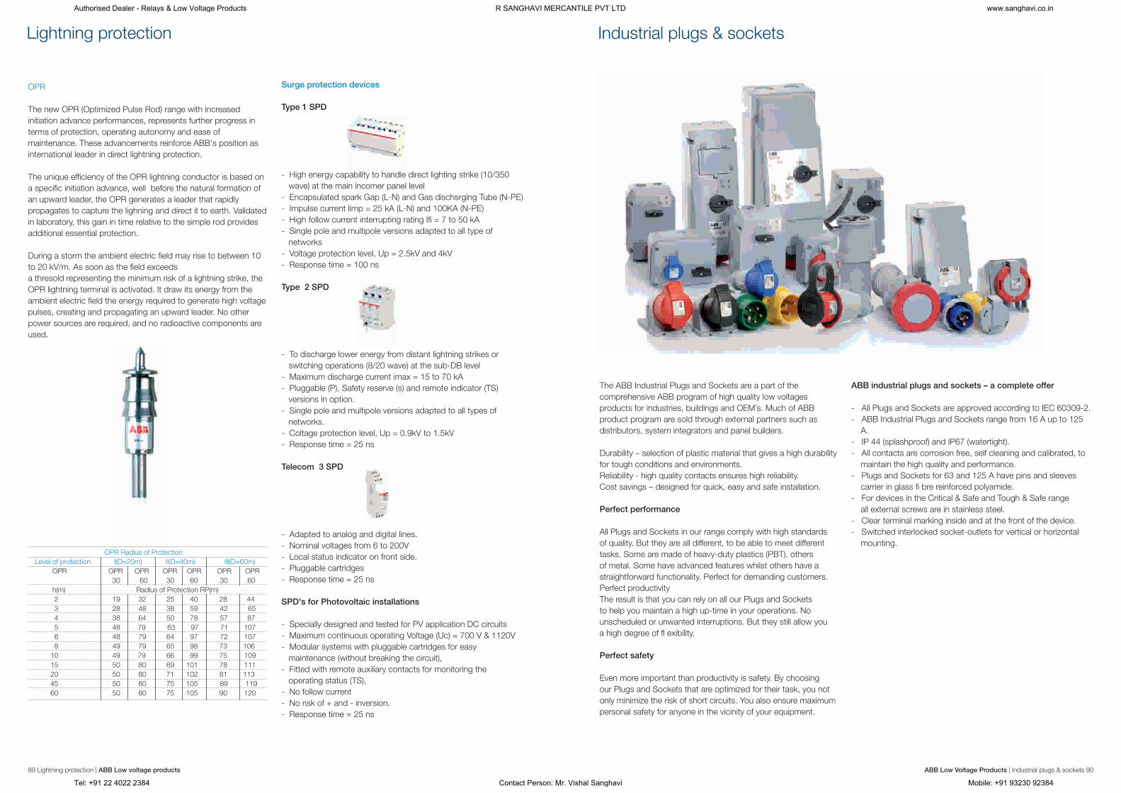
Lightning protection
89 Lightning protection | ABB Low voltage products ABB Low Voltage Products | Industrial plugs & sockets 90
Surge protection devices
Type 1 SPD
- High energy capability to handle direct lighting strike (10/350
wave) at the main incomer panel level
- Encapsulated spark Gap (L-N) and Gas dischsrging Tube (N-PE)
- Impulse current limp = 25 kA (L-N) and 100KA (N-PE)
- High follow current interrupting rating Ifi = 7 to 50 kA
- Single pole and multipole versions adapted to all type of
networks
- Voltage protection level, Up = 2.5kV and 4kV
- Response time = 100 ns
Type 2 SPD
- To discharge lower energy from distant lightning strikes or
switching operations (8/20 wave) at the sub-DB level
- Maximum discharge current imax = 15 to 70 kA
- Pluggable (P), Safety reserve (s) and remote indicator (TS)
versions in option.
- Single pole and multipole versions adapted to all types of
networks.
- Coltage protection level, Up = 0.9kV to 1.5kV
- Response time = 25 ns
Telecom 3 SPD
- Adapted to analog and digital lines.
- Nominal voltages from 6 to 200V
- Local status indicator on front side.
- Pluggable cartridges
- Response time = 25 ns
SPD's for Photovoltaic installations
- Specially designed and tested for PV application DC circuits
- Maximum continuous operating Voltage (Uc) = 700 V & 1120V
- Modular systems with pluggable cartridges for easy
maintenance (without breaking the circuit),
- Fitted with remote auxiliary contacts for monitoring the
operating status (TS),
- No follow current
- No risk of + and - inversion.
- Response time = 25 ns
OPR
The new OPR (Optimized Pulse Rod) range with increased
initiation advance performances, represents further progress in
terms of protection, operating autonomy and ease of
maintenance. These advancements reinforce ABB's position as
international leader in direct lightning protection.
The unique efficiency of the OPR lightning conductor is based on
a specific initiation advance, well before the natural formation of
an upward leader, the OPR generates a leader that rapidly
propagates to capture the lighning and direct it to earth. Validated
in laboratory, this gain in time relative to the simple rod provides
additional essential protection.
During a storm the ambient electric field may rise to between 10
to 20 kV/m. As soon as the field exceeds
a thresold representing the minimum risk of a lightning strike, the
OPR lightning terminal is activated. It draw its energy from the
ambient electric field the energy required to generate high voltage
pulses, creating and propagating an upward leader. No other
power sources are required, and no radioactive components are
used.
Industrial plugs & sockets
The ABB Industrial Plugs and Sockets are a part of the
comprehensive ABB program of high quality low voltages
products for industries, buildings and OEM´s. Much of ABB
product program are sold through external partners such as
distributors, system integrators and panel builders.
Durability – selection of plastic material that gives a high durability
for tough conditions and environments.
Reliability - high quality contacts ensures high reliability.
Cost savings – designed for quick, easy and safe installation.
Perfect performance
All Plugs and Sockets in our range comply with high standards
of quality. But they are all different, to be able to meet different
tasks. Some are made of heavy-duty plastics (PBT), others
of metal. Some have advanced features whilst others have a
straightforward functionality. Perfect for demanding customers.
Perfect productivity
The result is that you can rely on all our Plugs and Sockets
to help you maintain a high up-time in your operations. No
unscheduled or unwanted interruptions. But they still allow you
a high degree of fl exibility.
Perfect safety
Even more important than productivity is safety. By choosing
our Plugs and Sockets that are optimized for their task, you not
only minimize the risk of short circuits. You also ensure maximum
personal safety for anyone in the vicinity of your equipment.
ABB industrial plugs and sockets – a complete offer
- All Plugs and Sockets are approved according to IEC 60309-2.
- ABB Industrial Plugs and Sockets range from 16 A up to 125
A.
- IP 44 (splashproof) and IP67 (watertight).
- All contacts are corrosion free, self cleaning and calibrated, to
maintain the high quality and performance.
- Plugs and Sockets for 63 and 125 A have pins and sleeves
carrier in glass fi bre reinforced polyamide.
- For devices in the Critical & Safe and Tough & Safe range
all external screws are in stainless steel.
- Clear terminal marking inside and at the front of the device.
- Switched interlocked socket-outlets for vertical or horizontal
mounting.
Authorised Dealer - Relays & Low Voltage Products R SANGHAVI MERCANTILE PVT LTD www.sanghavi.co.in
Tel: +91 22 4022 2384 Contact Person: Mr. Vishal Sanghavi Mobile: +91 93230 92384

Distribution boards
ABB's S-series of distribution boards meet all the requirements of
modern installation for domestic, commercial or industrial
applications. Distribution boards undergo a seven-tank
phosphating process and powder coating to ensure an anti- rust
conditioning, superior finish and lasting strength. The S-series of
ABB distribution boards are manufactured with precision and are
of high quality CRCA steel sheets. These distribution boards It is
available in Ivory (RAL 9010) colour.These distribution boards are
perfect blend of aesthetics, functionality and safety provided with
top and bottom removable gland plates with adequate number of
knockouts, which enable easy installation and connection of
conduits of all sizes The S-series of ABB Distribution boards are
universal mounting types, hence can be flush or wall mounted.
(upto 36mm dia knockout).Double door construction of
distribution Boards facilitates easy removal of door intermediate
plate.
S-series Distribution boards offer two types of protection-IP43
degree with a metal door and IP20 degree without a door.
The highest degree of attention has been paid to the safety aspect
of the Distribution boards, considering that they are installed
in close proximity to people. An intermediate plate ensures total
safety, as no live parts are exposed when the door is opened.
SHC – SPN consumer units
Horizontal single phase consumer unit with provision for 2 pole
(MCB / Isolator / RCD) incoming and single phase outgoing.
These distribution boards come with neutral link, earth link and
100A tinned electrolytic copper busbar. Top and bottom,
removable gland plates with knockouts. Mounting of these boards
can be flush or surface. Number of ways : 4, 6, 8, 10, 12, 14, 16,
20
91 Distribution boards | ABB Low voltage products ABB Low voltage products | Distribution boards 92
A perfect blend of aesthetics, functionality and safety
SHDB – TPN distribution boards
Horizontal three phase distribution board provision for incomer 8
pole (MCB / Isolator / RCD)and single phase outgoings.
These distribution boards come with neutral link, earth link, 100A
tinned electrolytic copper busbar and wire sets for cable
management. Top and bottom, removable gland plates with
knockouts. Mounting of these boards can be flush or surface.
Number of ways : 4, 6, 8, 12
SHPPI – Horizontal per-phase Isolation Distribution Board
Horizontal per-phase Isolation Distribution Board with provision for
8 pole (MCB / Isolator / RCD) as incomer and 2 pole (MCB /
Isolator / RCD) sub-incomers with single phase as part of the
outgoings. Separate neutral links are provided for per phase
isolation. These Distribution Boards come with earthing link, 100A
tinned electrolytic copper busbar and top and bottom removable
gland plates with knockouts. Mounting of these boards can be
flush or surface. Number of ways : 6, 8, 12, 16
S7SEG – Seven segment distribution board
Seven Segment distribution board with phase segregation and
separation between incoming and outgoing with provision for 8P
incomer (MCB / Isolator / RCD) and 4 pole sub-income (MCB /
Isolator / RCD) with single phase outgoing. These distribution
boards come with earthing link, neutral bar and wire sets for cable
management for each compartment. Top and bottom, removable
gland plates with knockouts. Mounting of these boards can
be flush or surface. Number of ways : 4, 6, 8, 12
SVFL – Tier distribution board
Total flexibility as per site needs – configuration as per your choice
of incomer and outgoing. Supply busbars need to be selected.
Top and bottom, removable gland plates with knockouts.
Mounting of these boards can be flush or surface. Number of
ways : 13 way 3 tier, 13 way 4 tier
SVDB – Vertical per-phase isolation distribution boards
Vertical per-phase Isolation distribution board in 4-tier structure
with provision for 8 pole (MCB / Isolator / RCD) incomer and
provision for 2 pole (MCB / Isolator / RCD) as subincomer with
single phase outgoing. Separate neutral links are provided for per
phase isolation. These distribution boards come with earthing link,
100A tinned electrolytic copper busbar and wire sets. Top and
bottom, removable gland plates with knockouts. Mounting of
these boards can be flush or surface.Number of ways : 6, 8, 12
SVTDB – Vertical TPN distribution board
Vertical three phase distribution board with provision for 8 pole
(MCB / Isolator / RCD) & FP MCCB as incomer with three phase
and single phase (TP/SP) outgoings, complete with insulated
busbar arrangement. Top and bottom, removable gland plates
with knockouts. Mounting of these boards can be
flush or surface. Number of ways : 4, 6, 8, 12
Plug and socket distribution board – SGK
This range offers a wide variety of plug sockets up to 63A. These
plug sockets can be used for single phase or three phase along
with MCBs or RCBOs. They can be universally mounted.
Authorised Dealer - Relays & Low Voltage Products R SANGHAVI MERCANTILE PVT LTD www.sanghavi.co.in
Tel: +91 22 4022 2384 Contact Person: Mr. Vishal Sanghavi Mobile: +91 93230 92384

Smart home and intelligent building control (KNX)
Audio video integration
ABB i-bus® KNX is the intelligent installation system that meets
the highest requirements for applications in modern home and
building control.
- ABB i-bus® KNX is based on the simple, yet proven KNX
technology which is now accepted as the world’s first open
Standard for the control of all types of intelligent buildings -
industrial, commercial or residential.
- With the ABB i-bus® KNX system, the buildings we occupy are
easier to manage and control, resulting in increased flexibility,
security, economic efficiency and convenience.
- The operational flexibility of an ABB i-bus® KNX electrical
installation allows the everyday working or living environment to
be easily adapted to the individual’s needs – now and in the
future.
- The ABB i-bus® KNX product range includes components
covering the complete spectrum of applications found in
today’s buildings, ranging from lighting and shutter control to
heating, ventilation, security, energy management, and many
more.
KNX is the creator of the open standard EIB -KNX technology –
the worldwide open STANDARD for all applications in home and
building control, ranging from lighting and shutter control to
various security systems, heating, ventilation, air conditioning,
monitoring, alarming, water control, energy management,
metering as well as household appliances, audio and lots more.
The technology can be used in new as well as in existing home
and building
KNX is approved as an International Standard
(ISO/IEC 14543-3) as well as an European
Standard (CENELEC EN 50090 and CEN EN
13321-1) and Chinese Standard (GB/Z 20965).
KNX is therefore future proof. KNX products
made by different manufacturers can be
combined – the KNX trademark logo
guarantees their interworking and interoperability. KNX is therefore
the world´s only open Standard for the control in both commercial
and residential buildings.
ABB i-bus® Eib-KNX – The standard bus system
93 | ABB Low voltage productsHome and intelligent building control ABB Low voltage products | 94Home and intelligent building control
Outputs for Switching with feedback:
SA/S X. X. 1
Uses potential free contacts starting from 2, 4,8 and 12 channels
to switch independent electrical loads via the ABB i-bus®. Manual
and visual operation. The device is especially suited for loads with
high surge currents e.g. flourescent lighting (AX) acc. EN 60669.
Available in current rating starting from 6 A to 20 A .
Shutters and blind control:
JA/S X.X.1
Controls independent shutter or sunblind drives including the
functions Up/Down, Step/Stop, Move to position, Sun protection
automatic control and Heating/cooling automatic control. Direct
manual operation, with or without EIB/KNX voltage connected.
Illumination and lght sensors:
SD/S X.X.1
MDRC Device for switching (16A-AC1) and dimming independent
groups of luminaries with elect. Ballasts and 1-10V control inputs,
via the ABB i-bus®. Manual and visual operation. A power supply
is not necessary.
Lighting control
- Switching/dimming
- Light Scenes/mood lighting
- Central/group switching
- Constant lighting control
Control of heating, Ventilation and air conditioning (HVAC)
- Individual room control
- Reduction during night time and absence
- Presence-dependent control
Remote maintenance/energy management
- Remote maintenance/fault reporting
- Load management
- Facility management
Shutter control
- Control of the shutters
- Weather-dependent control
- Energy optimization
Security system
- Intrusion
- Fire
- Technical alarms (gas/water)
Visulisation
- Control
- Operation
- Synoptic/displays
Product range overview
Power supplies for KNX system voltage:
SV/S 30.X.5
Power supply with integrated choke for the ABB i-bus® system
voltage. Additional 30 V DC output to supply a second line in
connection with a separate choke. Connected to the bus line via
a bus connecting terminal. Available in 160 mA , 320 mA and 640
mA range. For supply of the KNX bus voltage in case of a mains
failure, a 12 V DC sealed lead acid battery can be connected with
uninterruptible KNX power supply.
Room master and room controller:
RM/S X.1
The Room Master opens new possibilities for objects where
rooms with a living area and bathroom are to be controlled and
utilized efficiently. The Room Master has been developed
especially for these areas typically found in hotels, hospitals,
assisted living accommodation and student residential homes. It
covers all the demands placed on the electrical installations of
these applications and offers the following functions in a compact
format: Switching of lighting, Control of heating/cooling,
Providing shade (via shutters or blinds), Switching of electrical
sockets and loads .The communication of the devices via the
KNX bus also implements central control functions as well as
sending of emergency signals from the rooms to a control centre.
Applications of ABB i-BUS®EIB-KNX
Authorised Dealer - Relays & Low Voltage Products R SANGHAVI MERCANTILE PVT LTD www.sanghavi.co.in
Tel: +91 22 4022 2384 Contact Person: Mr. Vishal Sanghavi Mobile: +91 93230 92384

95 | ABB Low voltage productsHome and intelligent building control ABB Low voltage products | 96Home and intelligent building control
UD/S 2.300.2
For switching and dimming incandescent lamps, 230 V halogen
lamps or low-voltage halogen lamps powered by wound or
electronic transformers. Automatic load detection. Full output
power up to 45 °C ambient temperature.
DG/S 1.X
For controlling DALI devices via the ABB i-bus®. Up to 128 DALI
Slaves are addressable. 64 DALI slaves can individually and
directly switched and dimmed. Additional 64 DALI devices are
controlled in broadcast mode.
6131-101
For switching up to two channels of illumination + one channel for
HVAC, dependent on brightness and/or movement Constant light
regulation Alarm function Surveillance zone (installation
Heating and Cooling:
FC/S 1.1
Controls motor-driven and thermal heating and ventilation valves
as well as multi-speed fans via the ABB i-bus® or as a stand-
alone device in combination with the temperature sensor. Two
binary inputs for 24 V AC signaling contacts
Visualization, Display and Signaling:
8136-500
The Busch- Comfort Touch combines the functions of a house
control, an infotainment centre and entertainment centre in one
attractive masterpiece. With the Busch- Comfort Touch, you can
operate or dim the lights, control your blinds, regulate the room
temperature or create scenes from a combination of the functions
listed – even by remote control. You can increase the security of
your house through presence simulation, alarm and information
messages. And if you want to know who is at the door or outside
the house, then switch the camera to exterior view and you will
immediately feel secure. You can also use the brilliant audio player
for MP3 files and a video player to play films. You can leave voice
and graphic messages for other family members, access e-mails,
track up-to-date stock market news, have a look at the weather
or the latest traffic reports or simply set a wake-up alarm. And all
this with an intuitive Touch Control, supported by a novel color
coding system. So you will certainly soon find that you do not
want to be without the Busch- Comfort Touch anymore
Voperation: Switch sensors
6344-XX
With Busch- priOn you can control and monitor the whole room
at the same time. Light, scenes, timer, blind control, heating
control – all functions are performed intuitively via a rotary
regulator. The 3.5’’ TFT display shows all information clearly.
Busch- priOn is not style frame bound and can be a modular
design layout. Freely programmable functions, such as light
scenes, blind functions or particular lights can be called up using
the switch rockers. Busch- priOn can be ideally adapted to all
customer requirements. There is a choice of three high-quality
design versions: “glass white”, “glass black” and stainless steel
with anti-fingerprint coating.
Energy Management:
ZS/S 1.1
Receives measuring data and values from ABB energy meters
such as DELTAplus, DELTAsingle, ODIN and ODINsingle and
transforms them into KNX telegrams. These data can be used e.g.
for visualisation, energy optimizing, billing and monitoring
purposes.
Security and surveillance:
MT/S X.12.1
Compact KNX security solution for the detection of intrusions and
technical alarms. The device provides 8 monitored inputs and 3
relay outputs. A 12 V DC SELV auxiliary supply is necessary. For
connection with magnetic reed contacts , door window contacts ,
glass breakage sensors , water detectors , smoke detectors ,
vibration detectors etc
TG/S 3.1
Sends configurable voice messages via the telephone network.
100 communication objects are available in the ETS program as
inputs or outputs. Apart from the voice messages, e-mail or SMS
messages can be sent. Commands via DTMF/MFV can be
executed.
Smart home and intelligent building control (KNX)
Authorised Dealer - Relays & Low Voltage Products R SANGHAVI MERCANTILE PVT LTD www.sanghavi.co.in
Tel: +91 22 4022 2384 Contact Person: Mr. Vishal Sanghavi Mobile: +91 93230 92384

97 Electrical wiring accessories | ABB Low voltage products
Electrical wiring accessories
Classiq Lumina
Current sensors Voltage sensors
Connection devices
ABB offers the best in class Electrical Wiring Accessories to suit
every domestic and commercial application. They are made from
high quality, UV resistant engineering plastics. These products
offer state-of-the-art design to suit different environment and add
aesthetic value to decor.
The ergonomically designed super-slim plates come with luminous
strip indicators that glow in the dark. The range has been
designed for high durability, world-class aesthetics and trouble-
free operation and is presented in a variety of colours and designs
to suit individual preferences.
The comprehensive array of Electrical Wiring Accessories ranges
from switches, sockets and support accessories like regulators,
data communication outlets and dimmers. ABB also offers state-
of-the-art building management systems
like ABB i-bus® EIB.
Features
- Ergonomically designed Switches
- Made from high quality, UV resistant engineering plastics
- Long full-length indicator for identification in the dark
- Bigger size Bell Push for special taste and blending with specia
décor
- Chamfered edges to avoid dust accumulation
- Extra slim plates (only 4 mm thick), but strong & flexible
Industry current sensors Substation and tractioncurrent sensors
Traction voltage sensors Traction voltage detectors
ABB connection devices
"The best in connection”
As a specialist in connection devices for 50 over years, ABB offers
one of the most comprehensive product ranges of terminal blocks
and PCB connectors on the market that meets most customer
requirements, from small panel builders to large OEMs, from
standard distribution and control panels, to the most specialized
applications in key industries such as traction, energy,
maritime, explosive atmospheres or electronic.
ABB offers the most standard connection in screw or screwless
technologies plus the exclusive ADO System ®, a unique
Insulation Displacement Connection (IDC) technology. Choose
from thousands of high quality standard terminal blocks and
functions. Whatever your requirements are, you will find the
connection products that fit your needs.
Our offering
Terminal Blocks
PCB Connection Devices
Test Blocks
Markers and Marking Systems
A turnkey package for your marking requirements
A complete range of terminal blocks to meet all your connection needs
A wide product range to ease your connection on PCB
Range
Switches: 6A-32A switches with and without indicators
Sockets: 6A-16A sockets and multi-pin international socket
in 2 module
Support accessories: Fan regulators, dimmers, communication
outlets
Mounting plate: 1module-16 module
Notes
Authorised Dealer - Relays & Low Voltage Products R SANGHAVI MERCANTILE PVT LTD www.sanghavi.co.in
Tel: +91 22 4022 2384 Contact Person: Mr. Vishal Sanghavi Mobile: +91 93230 92384