low voltage compact ns - switchgear...
TRANSCRIPT

Catalogue2011
Low Voltage
Compact NS Circuit breakers and switch-disconnectorsfrom 630b to 3200 A


I
Compact NSSetting the standard, once again...The launch of Schneider Electric Compact NS in 1994 revolutionised the world of moulded-case circuit breakers. Innovative, flexible and attractive, Compact NS rapidly set the standard in its field.
Today, Schneider Electric continues to innovate, extending the Compact NS range to high power ratings to offer a comprehensive and consistent range from 630b to 3200 A.
Equipped with the new generation of Micrologic control units, Compact NS630b to 3200 circuit breakers now offer built-in power and energy metering in addition to electrical measurement and analysis functions.
The communications option makes it possible to control power consumption, simplify maintenance and improve operating comfort. A wide range of optimised auxiliaries and accessories is also available to meet the needs of even more applications.
Compact NS, simply a step ahead…

II
Compact NS rangeMore than 10 years of techniques and technologies...
Inventor of the unique system-block concept, Schneider Electric proposes a range of circuit breakers to meet the concerns of panel builders and contractors. The result of 30 years of experience in the field of electrical distribution, the Compact NS range is still today the international reference on the moulded case circuit breaker market.
Consistency
The Compact NS range is available in 2 sizes only in order to homogenise installation dimensions, thus reducing switchboard dimensions and facilitating their installation: volume, depth, pole pitch and fastening points are the same for each size.
Efficiency
The Compact NS technology satisfies all your needs from 630b to 3200 A, with a breaking capacity from 50 to 200 kA.
Equipped with electronic control units, the Compact NS circuit breakers guarantee protection and measurement of your electrical installation.
FlexibilityCompact NS adapts to all your applications: protection of AC installations, generator protection, motor protection, applications in 1000 V, switch-disconnectors, source changeover switches.
With Compact NS you have the choice.
Open- endedness Compact NS evolves together with your installation: interchangeable trip units, standardised accessories, changing of rating without disassembling the device and addition of indication and control functions make Compact NS the most flexible solution on the market.
> Compact NS field installable devices
Marine Airports Oil and gas Wind mills
An answer for each type of solutions:

III
… ahead quite simply
The Compact NS range covers all ratings from 630b to 3200 A:
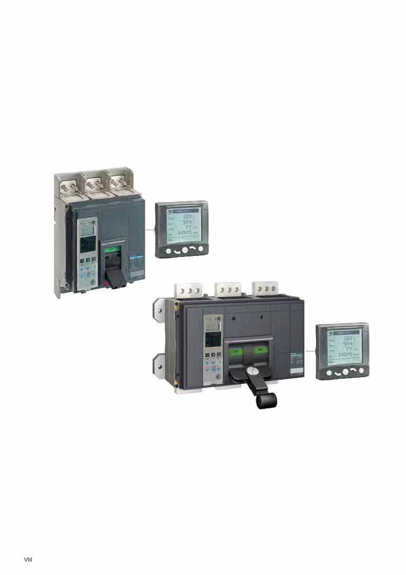
• Compact NS from 630b to 1600 A, fixed or withdrawable, front or rear connection, manual operating mechanism or motor mechanism. A new 200 kA performance now completes the Compact NS range.
• Compact NS from 1600 to 3200 A, fixed, front connection, with manual operating mechanism.
Compact NS1600b to 3200
Compact NS630b to 1600
2 sizes:
from 630b to 3200 A
NS630bLB 200 kA
H 150 kA
H 70 kA
N 50 kA
NS800 NS1000 NS1250 NS1600
H 85 kA
H 70 kA
NS1600b NS2000 NS2500 NS3200
Even in the hardest conditions, Compact NS is the circuit breaker to choose

IV
Optimising the management of your electrical installation
EGX300 gateway-server or iRIO RTUThe EGX300 web-enabled gateway-server or the iRIO RTU (remote terminal unit) can both be used as Ethernet coupler for the PowerLogic System devices and for any other communicating devices operating under Modbus RS485 protocol. Data is viewable via a standard web browser.
PowerLogic ION EnterprisePowerLogic ION Enterprise software is a complete power management solution for your facility or plant operations. It can be connected to Masterpact through Ethernet/Modbus protocol.
When equipped with a Micrologic types S, A, E or P, Compact NS can be integrated in a general supervision system to optimise installation operation and maintenance. Alarms may be programmed for remote indications. Used with PowerLogic ION Enterprise software, you can exploit the electrical data (current, voltage, energy, frequency, power, and power quality) to optimise continuity of service and energy management:
• reduce energy and operations costs;
• improve power quality, reliability and uptime;
• optimise equipment use.
FDM121 switch-board display unit
Ethernet (TPC / IP/ modbus)
Modbus
Compact NS Compact NSX
Internet
iRIO RTU / EGX300
Modbus IFM interface
@Firewall
FDM121
Modbus
Micrologic E
BCM ULP
Module BCM ULP Enables local and remote data access
Compact NS range...

V
A solution for all application types: Compact NS and Compact NSX
BuildingHotels @Hospitals @Offices @Retail @
Data Centres and Networks
IndustryMining and minerals @Automotive @Food and beverage @Chemical industry @
Energy and InfrastructuresAirports @Oil and gas @Water @Electrical energy @ Marine @
DC applicationsA specific range from 100 to 630 A with performance up to 100 kA and 750 V for battery or traction network type applications.
Motor applicationsAssociated with specific control units, the Compact range ensures motor protection functions up to 750 kW, and includes a dedicated product, Compact NS80H-MA, for applications up to 37 kW.
1000 V / 400 Hz applicationsThe Compact range covers 1000 V / 400 Hz
applications up to 630 A: road and rail tunnels, mines, wind turbines (1000 V) and aircraft facilities (400 Hz).
Source changeoverThe Compact range proposes interlocking solutions between two devices to perform the source changeover switch function. As from 100 A, a motor mechanism ensures automatic replacement of the main source by a secondary source in order to ensure permanent availability of energy. Applications are numerous: operating theatres, emergency lighting systems, computer rooms, bank security, etc.

VI
…for an installation with a longer service life
Electrical Energy
Industry Building, shopping malls
Data centres and networks
Hospitals
Total control of discrimination for optimum continuity of supplyThe result of a technology that has since inspired all major manufacturers, Compact NS offers an unparalleled discrimination level on the electrical distribution market.Fully incorporated in product design, discrimination is available as standard on all the range devices, without addition of any extra accessories. Should a fault occur, only the circuit breaker placed immediately upstream from the fault trips. Continuity of supply is thus guaranteed for the other feeders.
A comprehensive range of trip units and control unitsto combine measurement and protectionThe trip unit becomes a genuine control unit for the Compact NS circuit breaker. It combines various types of measurement with various types of protection. It measures accurately network parameters, immediately calculates values, memorises, logs, reports, communicates, acts, etc. It is both an extremely reliable protection device and an accurate measuring instrument. With the Micrologic E, P and H power measurement and advanced protection functions are now available in the Compact NS range.
Highly immune protection system insensitive to disturbances for more reliable operationInsensitive to external disturbances, the Compact NS range complies with the strictest requirements defined by standard IEC 60947-2 (Appendix F). Devices are able to operate in their electromagnetic environment without generating disturbances that could result in loss of quality, create a malfunction or a failure in the electrical installation.

VII
All the guarantees of a leading brand
CertificationThe reliability of the Compact NS range circuit breakers must be total. Such reliability is obtained thanks to faultless quality at all stages, from design to operation, in complete compliance with international standards and local certification.
Distribution and service networkWith more than 5000 sales outlets in 130 countries, you are guaranteed to find world-wide the range of products complying with your needs and satisfying user country standards perfectly.
Environmentally friendly productsSchneider Electric commits itself to an environmental approach, manufacturing products in keeping with the requirements of European Directive RoHS (Restriction of Hazardous Substances) in non-polluting ISO 14001 certified manufacturing units.
Tools for easy designFull documentation, CAD software and a library are available to assist you in all stages of installation design.
VIII

Compact NS630b to 3200 General contents
Presentation 2
Functions and characteristics A-1
Installation recommendations
B-1
Dimensions and connection
C-1
Wiring diagrams D-1
Additional characteristics E-1
1

2
Micrologic 5.0 E
40
100%
%
.
. .
.
.
..
.
menu
NS 1200 H
Ui 1000V Uimp 12kV
Ics = 100% Icu
IEC 947-2
UTE VDE BS CEI UNE NEMA
Ue(V)220/240
480/690
Icu(kA)
100
85
Uimp 8kV
Presentation
Compact NS, even more applications
Functions
They can be combined with the FDM121 switchboard display unit to provide all the functions of a Power Meter as well as operating assistance.
Applications
Power Meter page A-18
All Compact circuit breakers are equipped with a Micrologic control unit that can be changed on site. Control units are designed to protect Power circuits and loads. Alarms may be programmed for remote indications. In addition to protection functions, Micrologic S/A/E/P control units offer all the functions of Power Meter products as well as operating-assistance for the circuit breaker.
DB
4015
61
DB
4015
62D
B40
1563
DB
4015
65D
B40
1564
DB
4015
66
N R
DB
4015
95
Operating assistance page A-20
Integration of measurement functions provides operators with operating assistance functions including alarms tripped by user-selected measurement values, time-stamped event tables and histories, and maintenance indicators.
Switchboard display unit page A-21
The main measurements can be read on the built-in screen of Micrologic 2 / 5 / 6 trip units. They can also be displayed on the FDM121 switchboard display unit along with pop-up windows signalling the main alarms.
Communication page A-28
Compact NS equipped with Micrologic 2 / 5 / 6 trip units provide communication capabilities. Breaker ULP cords connect to a Modbus interface module.

3
Protection of LV distribution systems
page A-2
Protection of motors feeders(AC 220/690 V)
page A-35
Control and isolation using switch-disconnectors
page A-37
Service connection
Source changeover systems
page A-44
Protection for:distribution systems supplied by transformers b distribution systems supplied by engine bgenerator sets long cables in IT and TN systems. b
Installation : in power switchboards. b
All circuit breakers in the Compact NS range offer positive contact indication and are suitable for isolation in compliance with standards IEC 60947-1 and 2.
When combined with a motor starter, Compact NS circuit breakers protect the cables and the starter against short-circuits. Equipped with an electronic trip unit, Compact NS circuit breakers also protect the cables, starter and motor against overloads.
The exceptional current-limiting capacity of Compact NS circuit breakers automatically ensures type-2 coordination with the motor starter, in compliance with standard IEC 60947-4-1.
Compact NS service connection circuit breakers are specially designed for the service-connection function:
lead seals and locking systems btripping curves certified by utilities bfast overload curves to limit the power supplied, etc. b
Interpact INV switch-disconnectors offering visible break (see the corresponding catalogue) can be combined with Compact NS circuit breakers to constitute the various types of service connections and meet the needs of all installation configurations.
A switch-disconnector version of Compact NS circuit breakers exists for circuit control and isolation.All the additional functions may be combined with the basic switch-disconnector function, including:
earth-leakage protection bmotor mechanism. b
For information on other switch-disconnector ranges, see the Interpact (offering positive contact indication and visible break) and Fupact (fuse switch) catalogues.
To ensure a continuous supply of power, some electrical installations are connected to two power sources:
a normal source ba replacement source to supply the installation b
when the normal source is not available.A mechanical and/or electrical interlocking system between two circuit breakers or switch-disconnectors avoids all risk of parallel connection of the sources during switching.
A source-changeover system can be: manual with mechanical device interlocking b remote controlled with mechanical and/or electrical bdevice interlocking automatic by adding a controller to manage bswitching from one source to the other on the basis of external parameters.
(See Source-changeover catalogue for dimensions, connections and electrical drawings).
Additional earth-leakage protection protects life and property against the risks of faulty insulation in the installation.
Depending on the circuit breaker, earth-leakage protection is provided by:
using a specific Micrologic control unit busing a Vigirex relay and separate toroids. b
Earth leakage
page A-36

4
Compliance with standardsCompact NS circuit breakers and auxiliaries comply with the following:
international recommendations: bIEC 60947-1 - general rules vIEC 60947-2 - circuit breakers vIEC 60947-3 - switches, disconnectors, switch-disconnectors, etc. vIEC 60947-4 - contactors and motor starters vIEC 60947-5.1 and following - control circuit devices and switching elements; v
automatic control componentsEuropean (EN 60947-1 and EN 60947-2) and the corresponding national b
standards:France NF vGermany VDE vU.K. BS vAustralia AS vItaly CEI vthe specifications of the marine classification companies (Veritas, Lloyd’s Register b
of Shipping, Det Norske Veritas, etc.)French standard NF C 79-130 and the recommendations issued by the CNOMO b
organisation for the protection of machine tools.For U.S. UL, Canadian CSA, Mexican NOM and Japanese JIS standards, please consult us.
Pollution degreeCompact NS circuit breakers are certified for operation in pollution-degree 3 environments as defined by IEC standard 60947 (industrial environments).
TropicalisationCompact NS circuit breakers have successfully passed the tests prescribed by the following standards for extreme atmospheric conditions:
IEC 60068-2-1 - dry cold (-55 °C) bIEC 60068-2-2 - dry heat (+85 °C) bIEC 60068-2-30 - damp heat (95 % relative humidity at 55 °C) bIEC 60068-2-52 - salt mist (severity level 2). b
Environmental protectionCompact NS circuit breakers take into account important concerns for environmental protection. Most components are recyclable and the parts of Compact NS630b to NS3200 circuit breakers are marked as specified in applicable standards.
Ambient temperatureCompact NS circuit breakers may be used between -25 °C and +70 °C. b
For temperatures higher than 40 °C (65 °C for circuit breakers used to protect motor feeders), devices must be derated as indicated in the documentation.
circuit-breakers should be put into service under normal ambient operating- btemperature conditions. Exceptionally, the circuit breaker may be put into service when the ambient temperature is between -35 °C and -25 °C.the permissible storage-temperature range for Compact NS circuit breakers in the original packing is -50 °C (1) to +85 °C.
DiscriminationAs standard, the Compact NS range ensures discrimination between two circuit breakers positioned in series in an installation.
IntroductionGeneral characteristics for NS630b to 3200 range
(1) -40 °C for Micrologic control units with an LCD screen.
Standardised characteristics indicated on the rating plate:Ui: rated insulation voltageUimp: rated impulse withstand voltageIcu: ultimate breaking capacity, for various values of the rated operational voltage Uecat: utilisation categoryIcw: rated short-time withstand currentIcs: service breaking capacity In: rated current
suitable for isolation
DB
4015
60
IEC 60947-2UTE VDE
BSCEIUNEASNEMA
Ui 800 V Uimp 8 kV
Icw 19.2kA / 1s cat B
NS630b H
Ue (V)
Compact
Icu(kA) Ics(kA)
220/240 a 70 35380/415 a 70 35440 a 65 32500/525 a 50 25660/690 a 42 21
50/60Hz
DB
1280
13
CB2
CB1
Presentation

5
Positive contact indicationAll Compact NS circuit breakers are suitable for isolation as defined in IEC standard 60947-2:
the isolation position corresponds to the O (OFF) position bthe operating handle cannot indicate the “OFF” position unless the contacts are b
effectively openpadlocks may not be installed unless the contacts are open. b
Installation of a rotary handle or a motor mechanism does not alter the reliability of the position-indication system.The isolation function is certified by tests guaranteeing:
the mechanical reliability of the position indication system bthe absence of leakage currents bovervoltage withstand capacity between upstream and downstream connections. b
Installation in class II switchboardsAll Compact NS circuit breakers are class II front face devices. They may be installed through the door of class II switchboards (as per IEC standard 60664), without downgrading switchboard insulation. Installation requires no special operations, even when the circuit breaker is equipped with a rotary handle or a motor mechanism.
Degree of protectionAs per standards IEC 60529 (IP degree of protection) and EN 50102 (IK degree of protection against external mechanical impacts).
Bare circuit breaker with terminal shields
With toggle IP40 IK07
With direct rotary handle IP40 IK07
standard / VDE
Circuit breaker installed in a switchboard
With toggle IP40 IK07
With direct rotary handle standard / VDE MCCCNOMO
IP40 IK07
IP435IP547
With extended rotary handle IP55 IK08
DB
1280
19D
B12
8018
DB
1280
17D
B12
8016
DB
1280
15
DB
4018
31

6
Protection of distribution systemsOverview of solutions
Protection of distribution systems means protection of:b systems supplied by a transformerb systems supplied by an engine generator setb long cables in IT and TN systems.
Power distribution
Selection of circuit breakers from 630 to 3200 A page A-10Rated current (A) 250 … 320 … 400 … 500… 640…
630 800 1000 1250 1600
Compact NS630b NS800 NS1000 NS1250 NS1600
Breaking capacity N 50 50 50 50 50(kA rms) H 70 70 70 70 70380/415 V L 150 150 150 - -
LB 200 200 - - -Rated current (A) 640 … 800 ... 1000 … 1250 …
1600 2000 2500 3200
Compact NS1600b NS2000 NS2500 NS3200
Breaking capacity N 70 70 70(kA rms) H 85 85 85380/415 V
Accompanying control units up to 3200 A page A-18Micrologic electronic control units may be used on all Compact NS630b to NS3200 circuit breakers and can be changed on site.
PB
1048
45_M
EP
B10
4844
_ME
DB
1280
23Presentation
DB
1280
21
DB
1280
22
G

A-1
Compact NS630b to 3200 Functions and characteristicsContents
Presentation 2
Protection of distribution systems A-2Compact NS circuit breakers from 630b up to 3200 A A-2
Micrologic control units A-6Overview of functions A-6For Compact NS630b to 3200 A-8Micrologic A "ammeter" A-10Micrologic E “energy” A-12Micrologic P "power" A-14
Power Meter functions A-18Micrologic A/E/P control unit with COM option (BCM ULP) A-18
Operating-assistance functions A-20Micrologic A/E/P control unit with COM option (BCM ULP) A-20
Switchboard-display functions A-21Micrologic A/E/P control unit with COM option (BCM ULP) A-21
Protection of distribution systems A-23Micrologic control units for Compact NS630b to 3200 A-23
Portable data acquisition A-26GetnSet A-26
Communication A-28Compact NS630b to 3200 COM option in Compact A-28Overview of functions A-29
Compact communication A-30Networks and sofware A-30RSU and RCU utilities A-32Supervision software A-33Communication wiring system A-34
Motor protection A-35Overview of solutions A-35
Earth-leakage protection A-36Overview of solutions A-36
Control and isolation A-37Overview of solutions A-37Compact NS630bNA to NS1600NA switch-disconnectors A-40Compact NS1600bNA to 3200NA switch-disconnectors A-42
Source-changeover systems A-44Presentation A-44Mechanical interlocking A-45Electrical interlocking A-46Remote-operated systems A-47Associated controllers A-48Compact NS630b to 1600 (fixed version) A-50Compact NS630b to 1600 (withdrawable version) A-51Compact NS1600b to 3200 (fixed version) A-69
Installation recommendations B-1Dimensions and connection C-1Electrical diagrams D-1Additional characteristics E-1
version: 1.0 554E2000TDM.indd

A-2
Protection of distribution systemsCompact NS circuit breakers from 630b up to 3200 A
PB
1048
42
Compact NS800L.
PB
1048
43
Compact NS2000H.
(1) 65 °C with vertical connections. See the temperature derating tables for other types of connections.(2) Ics: 100 % Icu for breaking capacity 440V/500V/660VIcs: 75 % Icu for breaking capacity 220V/380V.
Compact circuit breakersNumber of poles Control manual toggle
direct or extended rotary handleelectric
Type of circuit breaker
Connections fixed front connectionrear connectionfront connection with bare cables
withdrawable (on chassis) front connectionrear connection
Electrical characteristics as per Nema AB1
Breaking capacity at 60 Hz (kA) 240 V480 V600 V
Electrical characteristics as per IEC 60947-2 and EN 60947-2
Rated current (A) In 50 °C65 °C (1)
Rated insulation voltage (V) Ui
Rated impulse withstand voltage (kV) Uimp
Rated operational voltage (V) Ue AC 50/60 HzType of circuit breaker
Ultimate breaking capacity (kA rms)
Manual lcu AC 50/60 Hz
220/240 V380/415 V440 V500/525 V660/690 V
lcs AC 50/60 Hz
220/240 V380/415 V440 V500/525 V660/690 V
Electrical lcu AC 50/60 Hz
220/240 V380/415 V440 V500/525 V660/690 V
lcs AC 50/60 Hz
220/240 V380/415 V440 V500/525 V660/690 V
Short-time withstand current (kA rms) lcw AC 50/60 Hz
1 s3 s
Integrated instantaneous protection kA peak ±10 %Suitability for isolationUtilisation categoryDurability (C-O cycles) mechanical
electrical 440 V In/2In
690 V In/2In
Pollution degree
Functions and characteristics

A-3
NS630b NS800 NS1000 NS1250 NS1600 NS1600b NS2000 NS2500 NS32003, 4 3, 4 3, 4 3, 4 3, 4b b b b bb b b b -b (except LB) b b b -N H L LB N H L N H N H N H
b b b - b b b b b b b b bb b b b b b b b b b b - -b b - - b b - b b - - - -b b b b b b b b b b b - -b b b b b b b b b b b - -N H L LB N H L N H N H N H
50 65 125 200 50 65 125 50 65 50 65 85 12535 50 100 200 35 50 100 35 50 35 50 65 8525 50 - 100 25 50 - 25 50 25 50 50 -
630 800 1000 1250 1600 1600 2000 2500 3200630 800 1000 1250 1510 1550 1900 2500 2970800 800 800 800 8008 8 8 8 8690 690 690 690 690N H L LB N H L N H N H N H
85 85 150 200 85 85 150 85 85 85 85 85 12550 70 150 200 50 70 150 50 70 50 70 70 8550 65 130 200 50 65 130 50 65 50 65 65 8540 50 100 100 40 50 100 40 50 40 50 65 -30 42 - 75 30 42 - 30 42 30 42 65 -50 52 150 200 50 52 150 50 52 37 37 65 9450 52 150 200 50 52 150 50 52 37 37 52 6450 48 130 200 50 48 130 50 48 25 32 65 6440 37 100 100 40 37 100 40 37 20 25 65 -30 31 - 75 30 31 - 30 31 15 21 65 -50 70 150 - 50 70 150 50 70 50 70 -50 70 150 - 50 70 150 50 70 50 7050 65 130 - 50 65 130 50 65 50 6540 50 100 - 40 50 100 40 50 40 5030 42 - - 30 42 - 30 42 30 4237 35 150 - 37 35 150 37 35 37 35 -37 35 150 - 37 35 150 37 35 37 3537 32 130 - 37 32 130 37 32 37 3230 25 100 - 30 25 100 30 25 30 2522 21 - - 22 21 - 22 21 22 2119.2 19.2 - - 19.2 19.2 - 19.2 19.2 19.2 19.2 -- - - - - - - - - - - 3240 40 - - 40 40 - 40 40 40 40 130b b b b bB B A A B B A B B B B B10000 10000 10000 10000 50006000 6000 4000 4000 6000 6000 4000 5000 5000 30005000 5000 3000 3000 5000 5000 3000 4000 2000 20004000 4000 3000 3000 4000 4000 3000 3000 2000 20002000 2000 2000 2000 2000 2000 2000 2000 1000 10003 3 3 3 3

A-4
Protection and measurements
Interchangeable control unitsOverload protection long time Ir (In x …)Short-circuit protection short time Isd (Ir x …)
instantaneous Ii (In x …)Earth-fault protection lg (In x …)Residual earth-leakage protection I∆nZone selective interlocking ZSI
Protection of the fourth poleCurrent measurementsPower measurementsAdvanced protectionQuick viewRemote communication by bus
Device-status indicationDevice remote operationTransmission of settingsIndication and identification of protection devices and alarmsTransmission of measured current values
Compact circuit breakersAdditional indication and control auxiliaries
Indication contactsVoltage releases MX shunt release/MN undervoltage releaseInstallation
Accessories terminal extensions and spreadersterminal shields and interphase barriersescutcheons
Dimensions fixed devices, front connections (mm) 3PH x W x D 4PWeight fixed devices, front connections (kg) 3P
4PSource changeover system (see section on "source changeover systems")
Manual, remote-operated and automatic source changeover systems (1) Except 1600b-3200.
Compact circuit breakers
Protection of distribution systemsCompact NS circuit breakers from 630b up to 3200 A
Functions and characteristics

A-5
Micrologic
2.0 5.0 6.0 2.0 A 5.0 A 6.0 A 7.0 A 2.0 E 5.0 E 6.0E 5.0 P (1) 6.0 P (1) 7.0 P (1)
b b b b b b b b b b b b b- b b - b b b - b b b b bb b b b b b b b b b b b b- - b - - b - - - b - b -- - - - - - b - - - b b b- - - b b b b - - - b b bb b b b b b b b b b b b b- - - b b b b b b b b b b- - - - b b b b b b b b b- - - - b b b b b b b b b- - - - - - - b b b - - -
b b b b b b b b b b b b bb b b b b - - b b b b b b- - b b b b b b b b b b b- - b b b b b b b b - - -- - b b b b b b b b b b b
NS630b NS800 NS1000 NS1250 NS1600 NS1600b NS2000 NS2500 NS3200
b bb b
b -b bb b327 x 210 x 147 350 x 420 x 160327 x 280 x 147 350 x 535 x 16014 2418 36
b -
NS630b NS800 NS1000 NS1250 NS1600 NS1600b NS2000 NS2500 NS3200
A-6
Functions and characteristics Micrologic control units Overview of functions
All Compact circuit breakers are equipped with a Micrologic control unit that can be changed on site.Control units are designed to protect Power circuits and loads. Alarms may be programmed for remote indications.Measurements of current, voltage, frequency, power and power quality optimise continuity of service and energy management.
DependabilityIntegration of protection functions in an ASIC electronic component used in all Micrologic control units guarantees a high degree of reliability and immunity to conducted or radiated disturbances.On Micrologic A, E and P control units, advanced functions are managed by an independent microprocessor.
AccessoriesCertain functions require the addition of Micrologic control unit accessories, described on page A-27.The rules governing the various possible combinations can be found in the documentation accessible via the Products and services menu of the www.schneider-electric.com web site.
Micrologic name codes Current protection
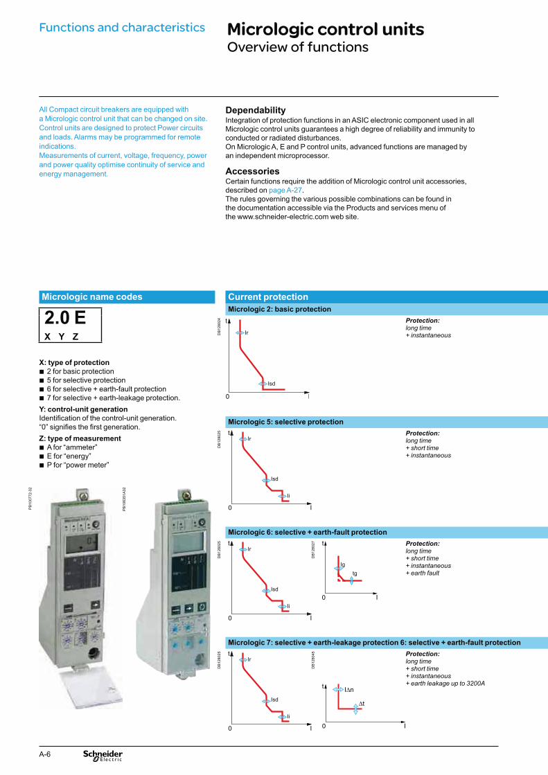
Micrologic 2: basic protection
2.0 EX Y Z
DB
1280
24 Protection:long time + instantaneous
X: type of protection
2 for basic protection b5 for selective protection b6 for selective + earth-fault protection b7 for selective + earth-leakage protection. b
Y: control-unit generation
Identification of the control-unit generation.“0” signifies the first generation.Z: type of measurement
A for “ammeter” bE for “energy” bP for “power meter” b
Micrologic 5: selective protection
DB
1280
25 Protection: long time + short time + instantaneous
PB
1007
72-3
2
PB
1063
51A
32
Micrologic 6: selective + earth-fault protection
DB
1280
25
DB
1280
27 Protection: long time + short time + instantaneous + earth fault
Micrologic 7: selective + earth-leakage protection 6: selective + earth-fault protection
DB
1280
25
DB
1280
45 Protection: long time + short time + instantaneous + earth leakage up to 3200A
A-7
Micrologic without
measurement
Measurements and programmable protection
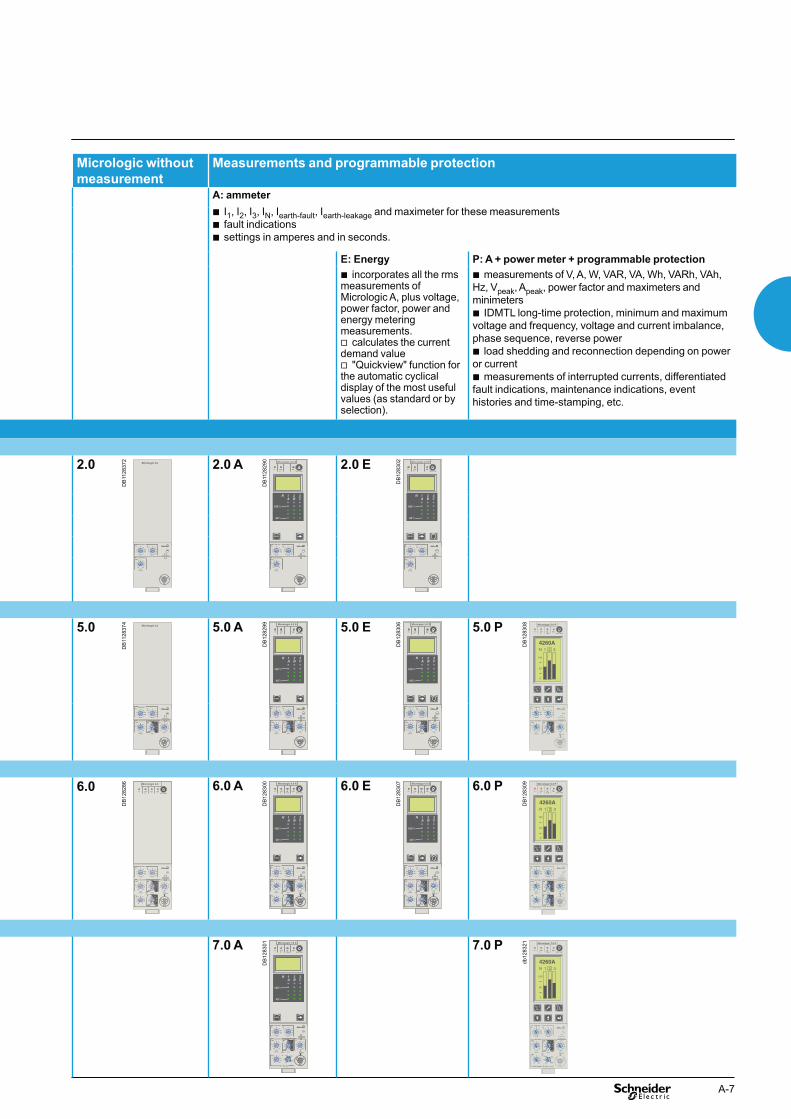
A: ammeter
I b 1, I2, I3, IN, Iearth-fault, Iearth-leakage and maximeter for these measurementsfault indications bsettings in amperes and in seconds. b
E: Energy P: A + power meter + programmable protection
incorporates all the rms bmeasurements of Micrologic A, plus voltage, power factor, power and energy metering measurements.
calculates the current vdemand value
"Quickview" function for vthe automatic cyclical display of the most useful values (as standard or by selection).
measurements of V, A, W, VAR, VA, Wh, VARh, VAh, bHz, Vpeak, Apeak, power factor and maximeters and minimeters
IDMTL long-time protection, minimum and maximum bvoltage and frequency, voltage and current imbalance, phase sequence, reverse power
load shedding and reconnection depending on power bor current
measurements of interrupted currents, differentiated bfault indications, maintenance indications, event histories and time-stamping, etc.
2.0
DB
1128
372
Micrologic 2.0
.4.5.6
.7.8
.9.95.98
1
x Ir
22.5
3 4 56
8101.5
setting
Isd
.512
48
121620
instantaneous
long timealarmIr tr
(s)
x In at 6 Ir24
2.0 A
DB
1128
290 Micrologic 2.0 A
40
100%
%
menu
long timealarm
instantaneous
.4.5.6
.7.8
.9.95.98
1
Ir
x In .512
48
121620
tr(s)
at 6 Ir24
x Ir
22.5
3 45
6
1.5
setting
Isd
810
2.0 E
DB
1283
02 Micrologic 2.0 E
40
100%
%
menu
long timealarm
instantaneous
.4.5.6
.7.8
.9.95.98
1
Ir
x In .512
48
121620
tr(s)
at 6 Ir24
x Ir
22.5
3 45
6
1.5
setting
Isd
810
5.0
DB
1128
374
Micrologic 5.0
setting delay
short timeI itsd
(s)
long timealarm
x In
34
68
101215
off2
.4.5.6
.7.8
.9.95.98
1
Ir
x In
x Ir
22.5
34 5
68
10
Isd
1.5
.512
48
121620
tr(s)
at 6 Ir24
on I2t
.2
.3.4 .4
.1
.2.3
.10
instantaneous
5.0 A
DB
1282
99 Micrologic 5.0 A
40
100%
%
menu
delay
short timetsd(s)
long timealarmtr
(s)
setting
.4.5.6
.7.8
.9.95.98
1
Ir
x In .512
4 8 121620
at 6 Ir24
x Ir
22.5
3 4 568
10
Isd
1.5on I2t
.2
.4 .4
.1
.3
.10
I i
x In
3
4
8
off2
.3
instantaneous
.26
15
1012
5.0 E
DB
1283
06 Micrologic 5.0 E
40
100%
%
delay
short timetsd(s)
long timealarmtr
(s)
setting
.4.5.6
.7.8
.9.95.98
1
Ir
x In .512
4 8 121620
at 6 Ir24
x Ir
22.5
3 4 568
10
Isd
1.5on I2t
.2
.4 .4
.1
.3
.10
I i
x In
3
4
8
off2
.3
instantaneous
.26
15
1012
menu
5.0 P
DB
1283
08 Micrologic 5.0 P
delaysettingx Ir
22.5
34 5
68
10
Isd
1.5
.4.5.6
.7.8
.9.95.98
1
short timeI itsd
(s)
on I2t
.2
.3.4 .4
.1
.2.3
.10off
instantaneous
long timealarmIr
x In .512
48
121620
tr(s)
@ 6 Ir24
x In
test
2
410
3
6 8
1215
off
4260AN 1 2 3
100
50
0
6.0
DB
1282
86 Micrologic 6.0
delay
short time
on I2t
.2
.3.4 .4
.1
.2
.10
long timealarm
ground fault
setting
4
test
.4.5.6
.7.8
.9.95.98
1
Ir
x In .512
48
121620
tr(s)
at 6 Ir24
x Ir
22.5
3 4 568
10
Isd
1.5
tsd(s)
x In
3
68 10
1215
off2
BC
D E FGH
I
Ig
Aon I
2t
.2
.3.4 .4
.1
.2.3
.10off
tg(s)
.1
.3instantaneous
I i
6.0 A
DB
1283
00 Micrologic 6.0 A
40
100%
%
menu
delay
short time
on I2t
.2
.3.4 .4
.1
.2
.10
long timealarm
ground fault
setting
4
test
.4.5.6
.7.8
.9.95.98
1
Ir
x In .512
48
121620
tr(s)
at 6 Ir24
x Ir
22.5
3 4 568
10
Isd
1.5
tsd(s)
x In
3
68 10
1215
off2
BC
D E FGH
I
Ig
Aon I
2t
.2
.3.4 .4
.1
.2.3
.10off
tg(s)
.1
.3instantaneous
I i
6.0 E
DB
1283
07 Micrologic 6.0 E
40
100%
%
delay
short time
on I2t
.2
.3.4 .4
.1
.2
.10
long timealarm
ground fault
setting
4
test
.4.5.6
.7.8
.9.95.98
1
Ir
x In .512
48
121620
tr(s)
at 6 Ir24
x Ir
22.5
3 4 568
10
Isd
1.5
tsd(s)
x In
3
68 10
1215
off2
BC
D E FGH
I
Ig
Aon I2t
.2
.3.4 .4
.1
.2.3
.10off
tg(s)
.1
.3instantaneous
I i
menu
6.0 P
DB
1283
09 Micrologic 6.0 P
.4.5.6
.7.8
.9.95.98
1
delay
short timeI itsd
(s)
on I2t
.2
.3.4 .4
.1
.2.3
.10off
instantaneous
long timealarmIr
x In
ground fault
BC
DE F
GH
J
Ig tg(s)
on I2t
.2
.3.4 .4
.1
.2.3
.10off
A
settingx Ir
22.5
3 4 568
10
Isd
1.5
.512
48
121620
tr(s)
@ 6 Ir24
x In
test
2
410
3
6 8
1215
off
4260AN 1 2 3
100
50
0
7.0 A
DB
1283
01 Micrologic 7.0 A
40
100%
%
menu
.98
delay
short time
off
long timealarm
setting
earth leakage
test
.4.5.6
.7.8
.9.95
1
Ir
x In
tr(s)
.512
48
121620
at 6 Ir24
x Ir
22.5
34 5
68
10
Isd
1.5
tsd(s)
on I2t
.2
.3.4 .4
.1
.2.3
.10
x In
34
6 8 1012
15off2
12
35 7
1020
30.5
IΔn
800
ΔI
60
140
230 350
instantaneousI i
7.0 P
db12
8321 Micrologic 7.0 P
.4.5.6
.7.8
.9.95.98
1
delay
short timeI itsd
(s)
on I2t
.2
.3.4 .4
.1
.2.3
.10off
instantaneous
long timealarmIr
x In
settingx Ir
22.5
34 5
68
10
Isd
1.5
.512
48
121620
tr(s)
@ 6 Ir24
800
earth leakage
12
35 7
1020
30
Δt(ms)
60.5
140
230 350
IΔn(A)
x In
test
2
410
3
6 8
12
15off
4260AN 1 2 3
100
50
0

A-8
1 long-time threshold and tripping delay2 overload alarm (LED)3 short-time pick-up and tripping delay4 instantaneous pick-up5 fixing screw for long-time rating plug6 test connector
ProtectionProtection thresholds and delays are set using the adjustment dials.Overload protection
True rms long-time protection.Thermal memory: thermal image before and after tripping.Setting accuracy may be enhanced by limiting the setting range using a different long-time rating plug.Overload protection can be cancelled using a specific LT rating plug "Off".Short-circuit protection
Short-time (rms) and instantaneous protection.Selection of I2t type (ON or OFF) for short-time delay.Earth-fault protection
Residual or source ground return earth fault protection.Selection of I2t type (ON or OFF) for delay.
Neutral protection
On three-pole circuit breakers, neutral protection is not possible.On four-pole circuit breakers, neutral protection may be set using a three-position switch: neutral unprotected (4P 3d), neutral protection at 0.5 Ir (4P 3d + N/2) or neutral protection at Ir (4P 4d).
IndicationsOverload indication by alarm LED on the front; the LED goes on when the current exceeds the long-time trip threshold.
TestA mini test kit or a portable test kit may be connected to the test connector on the front to check circuit-breaker operation after installing the trip unit or accessories.
Micrologic 2.0, 5.0 and 6.0 control units protect power circuits. Micrologic 5.0 and 6.0 offers time discrimination for short-circuits as well.
Note.Micrologic control units are equipped with a transparent lead-seal cover as standard.
Micrologic control unitsFor Compact NS630b to 3200
DB
1280
30Functions and characteristics

A-9
Protection Micrologic 2.0Long time
Current setting (A) Ir = In x … 0.4 0.5 0.6 0.7 0.8 0.9 0.95 0.98 1tripping between 1.05 and 1.20 x Ir other ranges or disable by changing long-time rating plugTime setting tr (s) 0.5 1 2 4 8 12 16 20 24 Time delay (s) accuracy: 0 to -30 % 1.5 x Ir 12.5 25 50 100 200 300 400 500 600
accuracy: 0 to -20 % 6 x Ir 0.7 (1) 1 2 4 8 12 16 20 24 accuracy: 0 to -20 % 7.2 x Ir 0.7 (2) 0.69 1.38 2.7 5.5 8.3 11 13.8 16.6
Thermal memory 20 minutes before and after tripping(1) 0 to -40 % - (2) 0 to -60 %Instantaneous
Pick-up (A) Isd = Ir x … 1.5 2 2.5 3 4 5 6 8 10accuracy: ±10 %Time delay max. resettable time: 20 ms; max break time: 80 ms
DB
1280
31
0 I
tIr
tr
Isd
Protection Micrologic 5.0 / 6.0Long time
DB
1280
32
Ir
tr
Isd
Ii
0 I
t
tsd
I2t off
I2t onCurrent setting (A) Ir = In x … 0.4 0.5 0.6 0.7 0.8 0.9 0.95 0.98 1Tripping between 1.05 and 1.20 x Ir Other ranges or disable by changing long-time rating plug Time setting tr (s) 0.5 1 2 4 8 12 16 20 24Time delay (s) Accuracy: 0 to -30 % 1.5 x Ir 12.5 25 50 100 200 300 400 500 600
Accuracy: 0 to -20 % 6 x Ir 0.7(1) 1 2 4 8 12 16 20 24Accuracy: 0 to -20 % 7.2 x Ir 0.7(2) 0.69 1.38 2.7 5.5 8.3 11 13.8 16.6
Thermal memory 20 minutes before and after tripping(1) 0 to -40 % - (2) 0 to -60 % Short time
Pick-up (A) Isd = Ir x … 1.5 2 2.5 3 4 5 6 8 10Accuracy: ±10 %Time setting tsd (s) Settings I2t Off 0 0.1 0.2 0.3 0.4
I2t On - 0.1 0.2 0.3 0.4Time delay (ms) at 10 x Ir tsd (max resettable time) 20 80 140 230 350(I2t Off or I2t On) tsd (max break time) 80 140 200 320 500Instantaneous
Pick-up (A) Ii = In x … 2 3 4 6 8 10 12 15 offAccuracy: ±10 %Time delay Max resettable time: 20 ms
Max break time: 50 ms
Earth fault Micrologic 6.0
DB
1280
36
Pick-up (A) Ig = In x … A B C D E F G H JAccuracy: ±10 % In y 400 A 0.3 0.3 0.4 0.5 0.6 0.7 0.8 0.9 1
400 A < In < 1250 A 0.2 0.3 0.4 0.5 0.6 0.7 0.8 0.9 1In u 1250 A 500 640 720 800 880 960 1040 1120 1200
Time setting tg (s) Settings I2t Off 0 0.1 0.2 0.3 0.4I2t On - 0.1 0.2 0.3 0.4
Time delay (ms) tg (max resettable time) 20 80 140 230 350at In or 1200 A (I2t Off or I2t On) tg (max break time) 80 140 200 320 500Note: all current-based protection functions require no auxiliary source. The test / reset button resets maximeters, clears the tripping indication and tests the battery.

A-10
Micrologic control unitsMicrologic A "ammeter"
1 long-time threshold and tripping delay2 overload alarm (LED) at 1.125 Ir3 short-time pick-up and tripping delay4 instantaneous pick-up5 earth-leakage or earth-fault pick-up and tripping delay6 earth-leakage or earth-fault test button7 long-time rating plug screw8 test connector9 lamp test, reset and battery test10 indication of tripping cause11 digital display12 three-phase bargraph and ammeter13 navigation buttons
Micrologic A control units protect power circuits. They also offer measurements, display, communication and current maximeters. Version 6 provides earth-fault protection, version 7 provides earth-leakage protection.
Note. Micrologic A control units come with a transparent lead-seal cover as standard.
"Ammeter" measurementsMicrologic A control units measure the true (rms) value of currents.They provide continuous current measurements from 0.2 to 1.2 In and are accurate to within 1.5 % (including the sensors).A digital LCD screen continuously displays the most heavily loaded phase (Imax) or displays the I1, I2, I3, IN, Ig,I∆n, stored-current (maximeter) and setting values by successively pressing the navigation button.The optional external power supply makes it possible to display currents < 20 % In.Below 0.1 In, measurements are not significant. Between 0.1and 0.2 In, accuracy changes linearly from 4 % to 1.5 %.
Communication optionIn conjunction with the COM communication option, the control unit transmits the following:
settings ball “ammeter” measurements btripping causes bmaximeter readings. b
ProtectionProtection thresholds and delays are set using the adjustment dials.Overload protection
True rms long-time protection.Thermal memory: thermal image before and after tripping.Setting accuracy may be enhanced by limiting the setting range using a different long-time rating plug.Overload protection can be cancelled using a specific LT rating plug "Off".Short-circuit protection
Short-time (rms) and instantaneous protection.Selection of I2t type (ON or OFF) for short-time delay.Earth-fault protection
Residual or source ground return earth fault protection.Selection of I2t type (ON or OFF) for delay.Residual earth-leakage protection (Vigi).
Operation without an external power supply. q Protected against nuisance tripping. k DC-component withstand class A up to 10 A.Neutral protection
On three-pole circuit breakers, neutral protection is not possible.On four-pole circuit breakers, neutral protection may be set using a three-position switch: neutral unprotected (4P 3d), neutral protection at 0.5 Ir (4P 3d + N/2), neutral protection at Ir (4P 4d).Zone selective interlocking (ZSI)
A ZSI terminal block may be used to interconnect a number of control units to provide total discrimination for short-time and earth-fault protection, without a delay before tripping.
Overload alarmA yellow alarm LED goes on when the current exceeds the long-time trip threshold.
Fault indicationsLEDs indicate the type of fault:
overload (long-time protection Ir) bshort-circuit (short-time Isd or instantaneous li protection) bearth fault or earth leakage (Ig or I∆n) binternal fault (Ap). b
Battery power
The fault indication LEDs remain on until the test/reset button is pressed. Under normal operating conditions, the battery supplying the LEDs has a service life of approximately 10 years.
TestA mini test kit or a portable test kit may be connected to the test connector on the front to check circuit-breaker operation. For Micrologic 6.0 A and 7.0 A control units, the operation of earth-fault or earth-leakage protection can be checked by pressing the test button located above the test connector.
DB
1280
33Functions and characteristics

A-11
Protection Micrologic 2.0 ALong time
DB
1280
31
0 I
tIr
tr
Isd
Current setting (A) 0.4 0.5 0.6 0.7 0.8 0.9 0.95 0.98 1Tripping between 1.05 and 1.20 x Ir Other ranges or disable by changing long-time rating plug Time setting tr (s) 0.5 1 2 4 8 12 16 20 24Time delay (s) Accuracy: 0 to -30 % 1.5 x Ir 12.5 25 50 100 200 300 400 500 600
Accuracy: 0 to -20 % 6 x Ir 0.7(1) 1 2 4 8 12 16 20 24Accuracy: 0 to -20 % 7.2 x Ir 0.7(2) 0.69 1.38 2.7 5.5 8.3 11 13.8 16.6
Thermal memory 20 minutes before and after tripping(1) 0 to -40 % - (2) 0 to -60 %Instantaneous
Pick-up (A) Isd = Ir x … 1.5 2 2.5 3 4 5 6 8 10Accuracy: ±10 %Time delay Max resettable time: 20 ms
Max break time: 80 ms
Protection Micrologic 5.0 / 6.0 / 7.0 ALong time Micrologic 5.0 / 6.0 / 7.0 A
DB
1280
32
Ir
tr
Isd
Ii
0 I
t
tsd
I2t off
I2t onCurrent setting (A) Ir = In x … 0.4 0.5 0.6 0.7 0.8 0.9 0.95 0.98 1Tripping between 1.05 and 1.20 x Ir Other ranges or disable by changing long-time rating plug Time setting tr (s) 0.5 1 2 4 8 12 16 20 24Time delay (s) Accuracy: 0 to -30 % 1.5 x Ir 12.5 25 50 100 200 300 400 500 600
Accuracy: 0 to -20 % 6 x Ir 0.7(1) 1 2 4 8 12 16 20 24Accuracy: 0 to -20 % 7.2 x Ir 0.7(2) 0.69 1.38 2.7 5.5 8.3 11 13.8 16.6
Thermal memory 20 minutes before and after tripping(1) 0 to -40 % - (2) 0 to -60 % Short time
Pick-up (A) Isd = Ir x … 1.5 2 2.5 3 4 5 6 8 10Accuracy: ±10 %Time setting tsd (s) Settings I2t Off 0 0.1 0.2 0.3 0.4
I2t On - 0.1 0.2 0.3 0.4Time delay (ms) at 10 x Ir tsd (max resettable time) 20 80 140 230 350(I2t Off or I2t On) tsd (max break time) 80 140 200 320 500Instantaneous
Pick-up (A) Ii = In x … 2 3 4 6 8 10 12 15 offAccuracy: ±10 %Time delay Max resettable time: 20 ms
Max break time: 50 ms
Earth fault Micrologic 6.0 A
DB
1280
36
Pick-up (A) Ig = In x … A B C D E F G H JAccuracy: ±10 % In y 400 A 0.3 0.3 0.4 0.5 0.6 0.7 0.8 0.9 1
400 A < In < 1250 A 0.2 0.3 0.4 0.5 0.6 0.7 0.8 0.9 1In u 1250 A 500 640 720 800 880 960 1040 1120 1200
Time setting tg (s) Settings I2t Off 0 0.1 0.2 0.3 0.4I2t On - 0.1 0.2 0.3 0.4
Time delay (ms) tg (max resettable time) 20 80 140 230 350at In or 1200 A (I2t Off or I2t On) tg (max break time) 80 140 200 320 500Residual earth leakage (Vigi) Micrologic 7.0 A
DB
1280
37
Sensitivity (A) IΔn 0.5 1 2 3 5 7 10 20 30Accuracy: 0 to -20 % Time delay Δt (ms) Settings 60 140 230 350 800
Δt (max resettable time) 60 140 230 350 800Δt (max break time) 140 200 320 500 1000
Ammeter Micrologic 2.0 / 5.0 / 6.0 / 7.0 A Type of measurements Range Accuracy
Instantaneous currents I1, I2, I3, IN 0.2 x In to 1.2 x In ± 1.5 %Ig (6.0 A) 0.2 x In to In ± 10 %IΔn (7.0 A) 0 to 30 A ± 1.5 %
Current maximeters of I1, I2, I3, IN 0.2 x In to 1.2 x In ± 1.5 %Note: all current-based protection functions require no auxiliary source. The test / reset button resets maximeters, clears the tripping indication and tests the battery.

A-12
Functions and characteristics Micrologic control unitsMicrologic E “energy”
1 long-time threshold and tripping delay2 overload alarm (LED) at 1.125 Ir3 short-time pick-up and tripping delay4 instantaneous pick-up5 earth-leakage or earth-fault pick-up and tripping delay6 earth-leakage or earth-fault test button7 long-time rating plug screw8 test connector9 lamp test, reset and battery test10 indication of tripping cause11 digital display12 three-phase bargraph and ammeter13 navigation button "quick View" (only with Micrologic E)14 navigation button to view menu contents15 navigation button to change menu
Micrologic E control units protect power circuits. They also offer measurements, display, communication and current maximeters. Version 6 provides earth-fault protection.
(1) Display on FDM121 only.
Note: Micrologic E control units come with a transparent lead-seal cover as standard.
"Energy meter" measurements
In addition to the ammeter measurements of Micrologic AMicrologic E control units measure and display:
current demand bvoltages: phase to phase, phase to neutral, average b (1) and unbalanced (1)
instantaneous power: P, Q, S bpower factor: PF bpower demand: P demand benergy: Ep, Eq b (1), Es (1).
Accuracy of active energy Ep is 2 % (including the sensors). The range of measurement is the same as current with Micrologic A, depending of an external power supply module (24 V DC).
Communication optionIn conjunction with the COM communication option, the control unit transmits the following:
settings ball "ammeter" and "energy" measurements benable connection to FDM121 btripping causes bmaximeter / minimeter readings. b
ProtectionProtection thresholds and delays are set using the adjustment dials.Overload protectionTrue rms long-time protection.Thermal memory: thermal image before and after tripping.Setting accuracy may be enhanced by limiting the setting range using a different long-time rating plug. Overload protection can be cancelled using a specific LT rating plug "Off".Short-circuit protectionShort-time (rms) and instantaneous protection. Selection of I2t type (ON or OFF) for short-time delay.Earth-fault protectionSource ground return earth fault protection.Selection of I2t type (ON or OFF) for delay.Neutral protectionOn three-pole circuit breakers, neutral protection is not possible.On four-pole circuit breakers, neutral protection may be set using a three-position switch: neutral unprotected (4P 3d), neutral protection at 0.5 Ir (4P 3d + N/2), neutral protection at Ir (4P 4d).Zone selective interlocking (ZSI)A ZSI terminal block may be used to interconnect a number of control units to provide total discrimination for short-time and earth-fault protection, without a delay before tripping.
Overload alarmA yellow alarm LED goes on when the current exceeds the long-time trip threshold.
Programmable contactsThe programmable contacts may be used to signal events (Ir, Isd, Alarm Ir, Alarm Ig, Ig). They can be programmed using the keypad on the Micrologic E control unit or remotely using the COM option (BCM ULP) and RSU software.
Fault indicationsLEDs indicate the type of fault:
overload (long-time protection Ir) bshort-circuit (short-time Isd or instantaneous li protection) bearth fault (Ig) binternal fault (Ap). b
Trip historyThe trip history displays the list of the last 10 trips. For each trip, the following indications are recorded and displayed:
the tripping cause: Ir, Isd, li, Ig or Auto-protection (Ap) trips bthe date and time of the trip (requires communication option). b
Battery powerThe fault indication LEDs remain on until the test/reset button is pressed. Under normal operating conditions, the battery supplying the LEDs has a service life of approximately 10 years.
TestA mini test kit or a portable test kit may be connected to the test connector on the front to check circuit-breaker operation. For Micrologic 6.0 E control units, the operation of earth-fault or earth-leakage protection can be checked by pressing the test button located above the test connector.
DB
1280
38
1415

A-13
Protection Micrologic 2.0 ELong time
DB
1280
31
0 I
tIr
tr
Isd
Current setting (A) 0.4 0.5 0.6 0.7 0.8 0.9 0.95 0.98 1Tripping between 1.05 and 1.20 x Ir Other ranges or disable by changing long-time rating plug Time setting tr (s) 0.5 1 2 4 8 12 16 20 24Time delay (s) Accuracy: 0 to -30 % 1.5 x Ir 12.5 25 50 100 200 300 400 500 600
Accuracy: 0 to -20 % 6 x Ir 0.7(1) 1 2 4 8 12 16 20 24Accuracy: 0 to -20 % 7.2 x Ir 0.7(2) 0.69 1.38 2.7 5.5 8.3 11 13.8 16.6
Thermal memory 20 minutes before and after tripping(1) 0 to -40 % - (2) 0 to -60 %Instantaneous
Pick-up (A) Isd = Ir x … 1.5 2 2.5 3 4 5 6 8 10Accuracy: ±10 %Time delay Max resettable time: 20 ms
Max break time: 80 ms
Protection Micrologic 5.0 / 6.0 ELong time Micrologic 5.0 / 6.0 E
DB
1280
32
Ir
tr
Isd
Ii
0 I
t
tsd
I2t off
I2t onCurrent setting (A) Ir = In x … 0.4 0.5 0.6 0.7 0.8 0.9 0.95 0.98 1Tripping between 1.05 and 1.20 x Ir Other ranges or disable by changing long-time rating plug Time setting tr (s) 0.5 1 2 4 8 12 16 20 24Time delay (s) Accuracy: 0 to -30 % 1.5 x Ir 12.5 25 50 100 200 300 400 500 600
Accuracy: 0 to -20 % 6 x Ir 0.7(1) 1 2 4 8 12 16 20 24Accuracy: 0 to -20 % 7.2 x Ir 0.7(2) 0.69 1.38 2.7 5.5 8.3 11 13.8 16.6
Thermal memory 20 minutes before and after tripping(1) 0 to -40 % - (2) 0 to -60 % Short time
Pick-up (A) Isd = Ir x … 1.5 2 2.5 3 4 5 6 8 10Accuracy: ±10 %Time setting tsd (s) Settings I2t Off 0 0.1 0.2 0.3 0.4
I2t On - 0.1 0.2 0.3 0.4Time delay (ms) at 10 x Ir tsd (max resettable time) 20 80 140 230 350(I2t Off or I2t On) tsd (max break time) 80 140 200 320 500Instantaneous
Pick-up (A) Ii = In x … 2 3 4 6 8 10 12 15 offAccuracy: ±10 %Time delay Max resettable time: 20 ms
Max break time: 50 ms
Earth fault Micrologic 6.0 E
DB
1280
36
Pick-up (A) Ig = In x … A B C D E F G H JAccuracy: ±10 % In y 400 A 0.3 0.3 0.4 0.5 0.6 0.7 0.8 0.9 1
400 A < In < 1250 A 0.2 0.3 0.4 0.5 0.6 0.7 0.8 0.9 1In u 1250 A 500 640 720 800 880 960 1040 1120 1200
Time setting tg (s) Settings I2t Off 0 0.1 0.2 0.3 0.4I2t On - 0.1 0.2 0.3 0.4
Time delay (ms) tg (max resettable time) 20 80 140 230 350at In or 1200 A (I2t Off or I2t On) tg (max break time) 80 140 200 320 500
Energy Micrologic 2.0 / 5.0 / 6.0 E Type of measurements Range Accuracy
Instantaneous currents I1, I2, I3, IN 0.2 x In to 1.2 x In ± 1.5 %Ig (6.0 E) 0.05 x In to In ± 10 %
Current maximeters of I1, I2, I3, IN 0.2 x In to 1.2 x In ± 1.5 %Demand currents of I1, I2, I3, Ig 0.2 x In to 1.2 x In ± 1.5 %Voltages V12, V23, V31, V1N, V2N, V3N 100 to 690 V ± 0.5 %Active power P 30 to 2000 kW ± 2 %Power factor PF 0 to 1 ± 2 %Demand power P demand 30 to 2000 kW ± 2 %Active energy Ep -1010 GWh to 1010 GWh ± 2 %Note: all current-based protection functions require no auxiliary source. The test / reset button resets maximeters, clears the tripping indication and tests the battery.

A-14
Micrologic control unitsMicrologic P "power"
Micrologic P control units include all the functions offered by Micrologic A.In addition, they measure voltages and calculate power and energy values.They also offer new protection functions based on currents, voltages, frequency and power reinforce load protection in real time.
Long-time current setting and tripping delay.1 Overload signal (LED).2 Short-time pick-up and tripping delay.3 Instantaneous pick-up.4 Earth-leakage or earth-fault pick-up and tripping delay.5 Earth-leakage or earth-fault test button.6 Long-time rating plug screw.7 Test connector.8 Lamp + battery test and indications reset.9 Indication of tripping cause.10 High-resolution screen.11 Measurement display.12 Maintenance indicators.13 Protection settings.14 Navigation buttons.15 Hole for settings lockout pin on cover.16
Note: Micrologic P control units come with a non-transparent lead-seal cover as standard.
Protection ........................................................ +
Protection settings The adjustable protection functions are identical to those of Micrologic A (overloads, short-circuits, earth-fault and earth-leakage protection).Fine adjustment
Within the range determined by the adjustment dial, fine adjustment of thresholds (to within one ampere) and time delays (to within one second) is possible on the keypad or remotely using the COM option.IDMTL (Inverse Definite Minimum Time Lag) settingCoordination with fuse-type or medium-voltage protection systems is optimised by adjusting the slope of the overload-protection curve. This setting also ensures better operation of this protection function with certain loads.Neutral protection
On three-pole circuit breakers, neutral protection may be set using the keypad or remotely using the COM option, to one of four positions: neutral unprotected (4P 3d), neutral protection at 0.5 Ir (4P 3d + N/2), neutral protection at Ir (4P 4d) and neutral protection at 1.6 Ir (4P 3d + 1.6N). Neutral protection at 1.6 Ir is used when the neutral conductor is twice the size of the phase conductors (major load imbalance, high level of third order harmonics).On four-pole circuit breakers, neutral protection may be set using a three-position switch or the keypad: neutral unprotected (4P 3d), neutral protection at 0.5 Ir (4P 3d + N/2), neutral protection at Ir (4P 4d). Neutral protection produces no effect if the long-time curve is set to one of the IDMTL protection settings.
Programmable alarms and other protectionDepending on the thresholds and time delays set using the keypad or remotely using the COM option, the Micrologic P control unit monitors currents and voltage, power, frequency and the phase sequence. Each threshold overrun is signalled remotely via the COM option. Each threshold overrun may be combined with tripping (protection) or an indication carried out by an optional M6C programmable contact (alarm), or both (protection and alarm).
Load shedding and reconnection Load shedding and reconnection parameters may be set according to the power or the current flowing through the circuit breaker. Load shedding is carried out by a supervisor via the COM option or by an M6C programmable contact.
Indication option via programmable contactsThe M6C (six contacts) auxiliary contacts may be used to signal threshold overruns or status changes. They can be programmed using the keypad on the Micrologic P control unit or remotely using the COM option (BCM ULP) and RSU software.
Communication option (COM)The communication option may be used to:
remotely read and set parameters for the protection functions btransmit all the calculated indicators and measurements bsignal the causes of tripping and alarms bconsult the history files and the maintenance-indicator register. bmaximeter reset. b
An event log and a maintenance register, stored in control-unit memory but not available locally, may be accessed in addition via the COM option.
DB
1280
42Functions and characteristics

A-15
Protection Micrologic 5.0 / 6.0 / 7.0 P +
Long time (rms) Micrologic 5.0 / 6.0 / 7.0 P
DB
1280
43
Current setting (A) Ir = In x … 0.4 0.5 0.6 0.7 0.8 0.9 0.95 0.98 1Tripping between 1.05 and 1.20 x Ir Other ranges or disable by changing long-time rating plug Time setting tr (s) 0.5 1 2 4 8 12 16 20 24Time delay (s) Accuracy: 0 to -30 % 1.5 x Ir 12.5 25 50 100 200 300 400 500 600
Accuracy: 0 to -20 % 6 x Ir 0.7(1) 1 2 4 8 12 16 20 24Accuracy: 0 to -20 % 7.2 x Ir 0.7(2) 0.69 1.38 2.7 5.5 8.3 11 13.8 16.6
IDMTL setting Curve slope SIT VIT EIT HVFuse DTThermal memory 20 minutes before and after tripping(1) 0 to -40 % - (2) 0 to -60 %Short time (rms)
Pick-up (A) Isd = Ir x … 1.5 2 2.5 3 4 5 6 8 10Accuracy: ±10 %Time setting tsd (s) Settings I2t Off 0 0.1 0.2 0.3 0.4
I2t On - 0.1 0.2 0.3 0.4Time delay (ms) at 10 Ir tsd (max resettable time) 20 80 140 230 350(I2t Off or I2t On) tsd (max break time) 80 140 200 320 500Instantaneous
Pick-up (A) Ii = In x … 2 3 4 6 8 10 12 15 off
DB
1280
44
Accuracy: ±10 %Time delay Max resettable time: 20 ms
Max break time: 50 msEarth fault Micrologic 6.0 P
Pick-up (A)Accuracy: ±10 %
Ig = In x … A B C D E F G H JIn y 400 A 0.3 0.3 0.4 0.5 0.6 0.7 0.8 0.9 1400 A < In < 1250 A 0.2 0.3 0.4 0.5 0.6 0.7 0.8 0.9 1In u 1250 A 500 640 720 800 880 960 1040 1120 1200
Time setting tg (s) Settings I2t Off 0 0.1 0.2 0.3 0.4I2t On - 0.1 0.2 0.3 0.4
Time delay (ms) tg (max resettable time) 20 80 140 230 350
DB
1280
45
at In or 1200 A (I2t Off or I2t On) tg (max break time) 80 140 200 320 500Residual earth leakage (Vigi) Micrologic 7.0 P
Sensitivity (A)Accuracy: 0 to -20 %
IΔn 0.5 1 2 3 5 7 10 20 30
Time delay Dt (ms) Settings 60 140 230 350 800Δt (max resettable time) 60 140 230 350 800Δt (max break time) 140 200 320 500 1000
Alarms and other protection Micrologic 5.0 / 6.0 / 7.0 PCurrent Threshold Delay
DB
1280
46
Current unbalance Iunbalance 0.05 to 0.6 Iaverage 1 to 40 sMax. demand current Imax demand : I1, I2, I3, IN, 0.2 In to In 15 to 1500 sEarth fault alarm
It 10 to 100 % In(3) 1 to 10 sVoltage
Voltage unbalance Uunbalance 2 to 30 % x Uaverage 1 to 40 sMinimum voltage Umin 100 to Umax between phases 1.2 to 10 sMaximum voltage(4) Umax Umin to 1200 between phases 1.2 to 10 sPower
Reverse power rP 5 to 500 kW 0.2 to 20 sFrequency
Minimum frequency Fmin 45 to Fmax 1.2 to 5 sMaximum frequency Fmax Fmin to 440 Hz 1.2 to 5 sPhase sequence
Sequence (alarm) ΔØ Ø1/2/3 or Ø1/3/2 0.3 s
Load shedding and reconnection Micrologic 5.0 / 6.0 / 7.0 P Measured value Threshold Delay
DB
1280
47
Current I 0.5 to 1 Ir per phases 20 % tr to 80 % trPower P 200 kW to 10 MW 10 to 3600 s
Power Micrologic 5.0 / 6.0 / 7.0 P Type of measurements Range Accuracy
Current maximeters of I1, I2, I3, IN 0.2 x In to 1.2 x In ± 1.5 %Voltages V12, V23, V31, V1N, V2N, V3N 100 to 690 V ± 0.5 %Power factor PF 0 to 1 ± 2 %Frequency (Hz) 0.1 %(3) In y 400 A 30 %400 A < In < 1250 A 20 %In u 1250 A 10 %
(4) For 690 V applications, a step-down transformer must be used if the voltage exceeds the nominal value of 690 V by more than 10 %.
Note: all current-based protection functions require no auxiliary source.Voltage-based protection functions are connected to AC power via a voltage measurement input built into the circuit breaker.
A-16
Micrologic control unitsMicrologic P "power"
Functions and characteristicsD
B10
1133
DB
1011
34
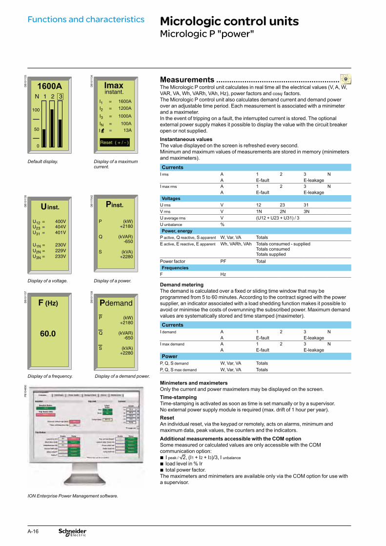
Measurements .........................................................The Micrologic P control unit calculates in real time all the electrical values (V, A, W, VAR, VA, Wh, VARh, VAh, Hz), power factors and cosϕ factors.The Micrologic P control unit also calculates demand current and demand power over an adjustable time period. Each measurement is associated with a minimeter and a maximeter.In the event of tripping on a fault, the interrupted current is stored. The optional external power supply makes it possible to display the value with the circuit breaker open or not supplied.Instantaneous values
The value displayed on the screen is refreshed every second. Minimum and maximum values of measurements are stored in memory (minimeters and maximeters).
Default display. Display of a maximum current. Currents
I rms A 1 2 3 NA E-fault E-leakage
I max rms A 1 2 3 NA E-fault E-leakage
DB
1011
35
DB
1170
42 Voltages
U rms V 12 23 31V rms V 1N 2N 3NU average rms V (U12 + U23 + U31) / 3U unbalance %Power, energy
P active, Q reactive, S apparent W, Var, VA TotalsE active, E reactive, E apparent Wh, VARh, VAh Totals consumed - supplied
Totals consumedTotals supplied
Power factor PF TotalFrequencies
F HzDisplay of a voltage. Display of a power.
Demand metering
The demand is calculated over a fixed or sliding time window that may be programmed from 5 to 60 minutes. According to the contract signed with the power supplier, an indicator associated with a load shedding function makes it possible to avoid or minimise the costs of overrunning the subscribed power. Maximum demand values are systematically stored and time stamped (maximeter).
DB
1011
37
DB
1011
38
Currents
I demand A 1 2 3 NA E-fault E-leakage
I max demand A 1 2 3 NA E-fault E-leakage
Power
P, Q, S demand W, Var, VA TotalsP, Q, S max demand W, Var, VA Totals
Display of a frequency. Display of a demand power.
PB
1048
50
Minimeters and maximeters
Only the current and power maximeters may be displayed on the screen.Time-stamping
Time-stamping is activated as soon as time is set manually or by a supervisor.No external power supply module is required (max. drift of 1 hour per year).Reset
An individual reset, via the keypad or remotely, acts on alarms, minimum and maximum data, peak values, the counters and the indicators.Additional measurements accessible with the COM option
Some measured or calculated values are only accessible with the COM communication option:
I b peak / 2, (I1 + I2 + I3)/3, I unbalanceload level in % Ir btotal power factor. b
The maximeters and minimeters are available only via the COM option for use with a supervisor.
ION Enterprise Power Management software.
A-17
DB
1170
41
DB
1011
40
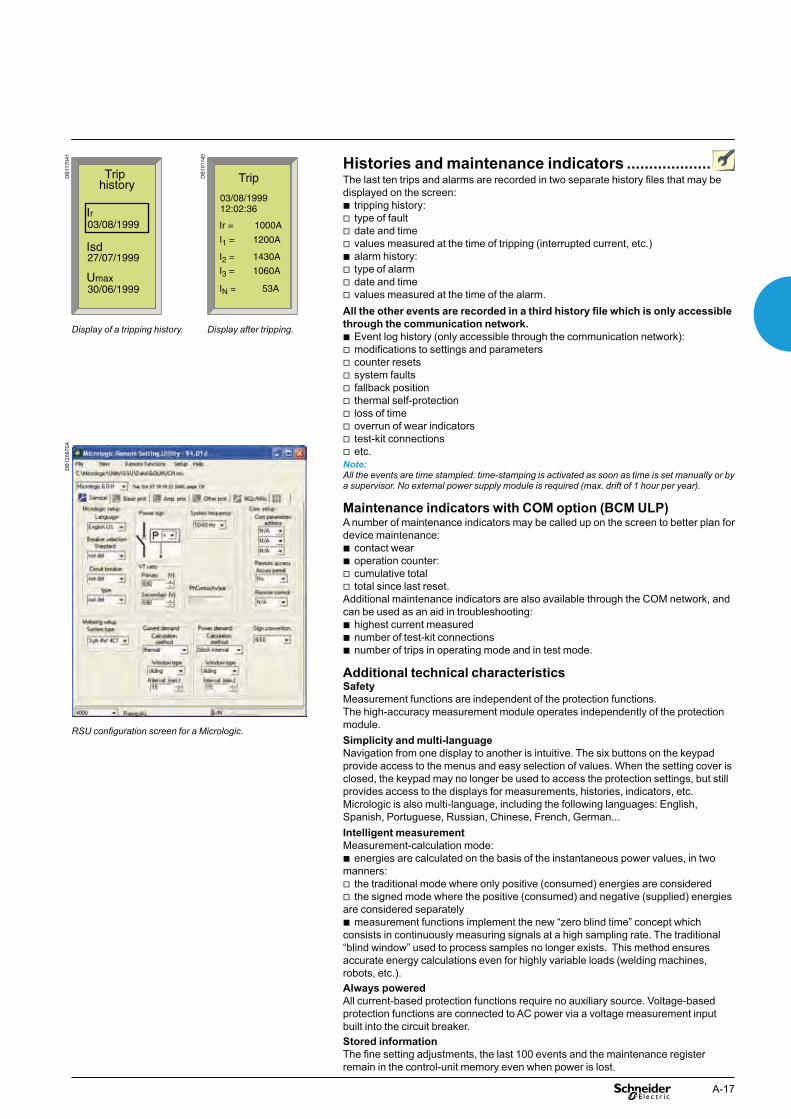
Histories and maintenance indicators ...................The last ten trips and alarms are recorded in two separate history files that may be displayed on the screen:
tripping history: btype of fault vdate and time vvalues measured at the time of tripping (interrupted current, etc.) valarm history: btype of alarm vdate and time vvalues measured at the time of the alarm. v
All the other events are recorded in a third history file which is only accessible through the communication network.
Event log history (only accessible through the communication network): bmodifications to settings and parameters vcounter resets vsystem faults vfallback position vthermal self-protection vloss of time voverrun of wear indicators vtest-kit connections vetc. v
Note: All the events are time stampled: time-stamping is activated as soon as time is set manually or by a supervisor. No external power supply module is required (max. drift of 1 hour per year).
Maintenance indicators with COM option (BCM ULP)A number of maintenance indicators may be called up on the screen to better plan for device maintenance:
contact wear boperation counter: bcumulative total vtotal since last reset. v
Additional maintenance indicators are also available through the COM network, and can be used as an aid in troubleshooting:
highest current measured bnumber of test-kit connections bnumber of trips in operating mode and in test mode. b
Additional technical characteristicsSafety
Measurement functions are independent of the protection functions.The high-accuracy measurement module operates independently of the protection module.Simplicity and multi-language
Navigation from one display to another is intuitive. The six buttons on the keypad provide access to the menus and easy selection of values. When the setting cover is closed, the keypad may no longer be used to access the protection settings, but still provides access to the displays for measurements, histories, indicators, etc.Micrologic is also multi-language, including the following languages: English, Spanish, Portuguese, Russian, Chinese, French, German...Intelligent measurement
Measurement-calculation mode:energies are calculated on the basis of the instantaneous power values, in two b
manners:the traditional mode where only positive (consumed) energies are considered vthe signed mode where the positive (consumed) and negative (supplied) energies v
are considered separatelymeasurement functions implement the new “zero blind time” concept which b
consists in continuously measuring signals at a high sampling rate. The traditional “blind window” used to process samples no longer exists. This method ensures accurate energy calculations even for highly variable loads (welding machines, robots, etc.).Always powered
All current-based protection functions require no auxiliary source. Voltage-based protection functions are connected to AC power via a voltage measurement input built into the circuit breaker.Stored information
The fine setting adjustments, the last 100 events and the maintenance register remain in the control-unit memory even when power is lost.
Display of a tripping history. Display after tripping.
DB
1209
70A
RSU configuration screen for a Micrologic.

A-18
Functions and characteristics Power Meter functionsMicrologic A/E/P control unit with COM option (BCM ULP)
In addition to protection functions, Micrologic A/E/P control units offer all the functions of Power Meter products as well as operating-assistance for the circuit breaker.
Micrologic A/E/P measurement functions are made possible by Micrologic intelligence and the accuracy of the sensors. They are handled by a microprocessor that operates independent of protection functions.
Display ..................................................................
FDM121 display unitThe FDM121 switchboard display unit can be connected to a Micrologic COM option (BCM ULP) using a breaker ULP cord to display all measurements on a screen. The result is a veritable 96 x 96 mm Power Meter.In addition to the information displayed on the Micrologic LCD, the FDM121 screen shows demand, power quality and maximeter/minimeter values along with histories and maintenance indicators.The FMD121 display unit requires a 24 V DC power supply. The COM option (BCM ULP) unit is supplied by the same power supply via the breaker ULP cord connecting it to the FDM121.
Measurements .....................................................
Instantaneous rms measurementsThe Micrologic continuously display the RMS value of the highest current of the three phases and neutral (Imax). The navigation buttons can be used to scroll through the main measurements.In the event of a fault trip, the trip cause is displayed.The Micrologic A measures phase, neutral, ground fault currents.The Micrologic E offers voltage, power, Power Factor, measurements in addition to the measurements provided by Micrologic A.The Micrologic P offer frequency, cos.ϕ in addition to the measurements provided by Micrologic E.
Maximeters / minimetersEvery instantaneous measurement provided by Micrologic A or E can be associated with a maximeter/minimeter. The maximeters for the highest current of the 3 phases and neutral, the demand current and power can be reset via the FDM121 display unit or the communication system.
Energy meteringThe Micrologic E/P also measures the energy consumed since the last reset of the meter. The active energy meter can be reset via Micrologic keypad or the FDM121 display unit or the communication system.
Demand and maximum demand valuesMicrologic E/P also calculates demand current and power values. These calculations can be made using a block or sliding interval that can be set from 5 to 60 minutes in steps of 1 minute. The window can be synchronised with a signal sent via the communication system. Whatever the calculation method, the calculated values can be recovered on a PC via Modbus communication. Ordinary spreadsheet software can be used to provide trend curves and forecasts based on this data. They will provide a basis for load shedding and reconnection operations used to adjust consumption to the subscribed power.
DB
12
59
11
Alarms
ServicesESC OK
Main Menu
Quick view
Control
Metering
FDM121 display: navigation.
DB
1121
31
I1I
%
310 A I2
%
315 A
I3
%
302 A IN
%
23 A
ESC
DB
1121
32
ESC
U1
U2
U3
V 4/7
402 V 100 120%
398 V 100 120%
401 V 100 120%
Current. Voltage.
DB
1121
33
ESC
P 64 kW
Q 38 kVar
S 51 kVA
PQS
DB
1121
34
ESC
Ep 14397 kWh
Eq 8325 kVarh
Es 13035 kVAh
E
Power. Consumption.
Examples of measurement screens on the FDM121 display unit.

A-19
Micrologic A/E/P integrated Power Meter functions Type DisplayA/E P Micrologic
LCDFDM121 display
Display of protection settings
Pick-ups (A) and delays All settings can be displayed Ir, tr, Isd, tsd, Ii, Ig, tg A/E P b -Measurements
Instantaneous rms measurements
Currents (A) Phases and neutral I1, I2, I3, IN A/E P b b
Average of phases Iavg = (I1 + I2 + I3) / 3 A/E P - b
Highest current of the 3 phases and neutral Imax of I1, I2, I3, IN A/E P b b
Ground fault (Micrologic 6) % Ig (pick-up setting) A/E P b b
Current unbalance between phases % Iavg - /E P - b
Voltages (V) Phase-to-phase V12, V23, V31 - /E P b b
Phase-to-neutral V1N, V2N, V3N - /E P b b
Average of phase-to-phase voltages Vavg = (V12 + V23 + V31) / 3 - /E P - b
Average of phase-to-neutral voltages Vavg = (V1N + V2N + V3N) / 3 - /E P - b
Ph-Ph and Ph-N voltage unbalance % Vavg and % Vavg - /E P - b
Phase sequence 1-2-3, 1-3-2 - / - P b b
Frequency (Hz) Power system f - / - P b b
Power Active (kW) P, total - /E P b b
P, per phase - /E P b (2) b
Reactive (kVAR) Q, total - /E P b b
Q, per phase - / - P b (2) b
Apparent (kVA) S, total - /E P b b
S, per phase - / - P b (2) b
Power Factor PF, total - /E P b b
PF, per phase - / - P b (2) b
Cos.ϕ Cos.ϕ, total - / - P b (2) b
Cos.ϕ, per phase - / - P b (2) b
Maximeters / minimeters
Associated with instantaneous rms measurements
Reset via FDM121 display unit and Micrologic keypad
A/E P b b
Energy metering
Energy Active (kW), reactive (kVARh), apparent (kVAh)
Total since last reset - /E P b b
Demand and maximum demand values
Demand current (A) Phases and neutral Present value on the selected window - /E P b b
Maximum demand since last reset - /E P b (2) b
Demand power Active (kWh), reactive (kVAR), apparent (kVA)
Present value on the selected window - /E P b b
Maximum demand since last reset - /E P b (2) b
Calculation window Sliding, fixed or com-synchronised Adjustable from 5 to 60 minutes in 1 minute steps (1)
- /E P - -
(1) Available via the communication system only.(2) Available for Micrologic P only.
PB
1048
42_2
4
PB
1033
60
PB
1063
51A
13

A-20
Functions and characteristics Operating-assistance functionsMicrologic A/E/P control unit with COM option (BCM ULP)
Histories .................................................................trip indications in clear text in a number of user-selectable languages btime-stamping: date and time of trip. b
Maintenance indicators .........................................Micrologic control unit have indicators for, among others, the number of operating cycles, contact wear P, load profile and operating times (operating hours counter) of the Masterpact circuit breaker. It is possible to assign an alarm to the operating cycle counter to plan maintenance.The various indicators can be used together with the trip histories to analyse the level of stresses the device has been subjected to.
Management of installed devicesEach circuit breaker equipped with a COM option (BCM ULP) can be identified via the communication system:
serial number bfirmware version bhardware version bdevice name assigned by the user. b
This information together with the previously described indications provides a clear view of the installed devices.
Micrologic A/E/P operating assistance functions Type DisplayA/E P Micrologic
LCDFDM121 display
Operating assistance
Trip history
Trips Cause of tripping Ir, Isd, Ii, Ig, IΔn - /E P b b
Maintenance indicators
Counter Mechanical cycles Assignable to an alarm A/E P - b
Electrical cycles Assignable to an alarm A/E P - b
Hours Total operating time (hours) (1) A/E P - -Indicator Contact wear % - / - P - b
Load profile Hours at different load levels % of hours in four current ranges: 0-49 % In, 50-79 % In, 80-89 % In and u 90 % In
A /E P - b
(1) Also available via the communication system.
Additional technical characteristicsContact wear Each time Compact opens, the Micrologic P trip unit measures the interrupted current and increments the contact-wear indicator as a function of the interrupted current, according to test results stored in memory. Breaking under normal load conditions results in a very slight increment. The indicator value may be read on the FDM121 display. It provides an estimation of contact wear calculated on the basis of the cumulative forces affecting the circuit breaker. When the indicator reaches 100 %, it is advised to inspect the circuit breaker to ensure the availability of the protected equipment.Circuit breaker load profileMicrologic A/E/P calculates the load profile of the circuit breaker protecting a load circuit. The profile indicates the percentage of the total operating time at four current levels (% of breaker In):
0 to 49 % In b50 to 79 % In b80 to 89 % In bu b 90 % In.
This information can be used to optimise use of the protected equipment or to plan ahead for extensions.

A-21
Switchboard-display functionsMicrologic A/E/P control unit with COM option (BCM ULP)
Micrologic measurement capabilities come into full play with the FDM121 switchboard display. It connects to COM option (BCM ULP) via a breaker ULP cord and displays Micrologic information. The result is a true integrated unit combining a circuit breaker and a Power Meter. Additional operating assistance functions can also be displayed.
FDM121 switchboard displayThe FDM121 switchboard display unit can be connected to a Micrologic COM option (BCM ULP). It uses the sensors and processing capacity of the Micrologic control unit. It is easy to use and requires no special software or settings. It is immediately operational when connected to the COM option (BCM ULP) by a breaker ULP cord.The FDM121 is a large display, but requires very little depth. The anti-glare graphic screen is backlit for very easy reading even under poor ambient lighting and at sharp angles.
Display of Micrologic measurements and tripsThe FDM121 is intended to display Micrologic A/E/P measurements, trips and operating information. It cannot be used to modify the protection settings.Measurements may be easily accessed via a menu. Trips are automatically displayed.
A pop-up window displays the time-stamped description of the trip and the orange bLED flashes
Status indicationsWhen the circuit breaker is equipped with the COM option (BCM ULP) (including its set of sensors) the FDM121 display can also be used to view circuit breaker status conditions:
O/F: ON/OFF bSDE: Fault-trip indication (overload, short-circuit, ground fault). bPF: ready to close bCH: charged (spring loaded). b
Remote controlWhen the circuit breaker is equipped with the COM option (BCM ULP) (including its kit for connection to XF and MX1 communication voltage releases), the FDM121 display can also be used to control (open/close) the circuit breaker. Two operating mode are available.
local mode : open/close commands are enabled from FDM121 while disable from bcommunication network
remote mode : open/close commands are disabled from FDM121 while, enabled bfrom communication network.
Main characteristics96 x 96 x 30 mm screen requiring 10 mm behind the door (or 20 mm when b
the 24 volt power supply connector is used).White backlighting. bWide viewing angle: vertical ±60 °, horizontal ±30 °. bHigh resolution: excellent reading of graphic symbols. bAlarm LED: flashing orange for alarm pick-up, steady orange after operator reset if b
alarm condition persists.Operating temperature range -10 °C to +55 °C. bCE / UL / CSA marking (pending). b24 V DC power supply, with tolerances 24 V -20 % (19.2 V) to 24 V +10 % (26.4 V). b
When the FDM121 is connected to the communication network, the 24 V DC can be supplied by the communication system wiring system (see paragraph "Connection").
Consumption 40 mA. b
MountingThe FDM121 is easily installed in a switchboard.
Standard door cut-out 92 x 92 mm. bAttached using clips. b
To avoid a cut-out in the door, an accessory is available for surface mounting by drilling only two 22 mm diameter holes.The FDM121 degree of protection is IP54 in front. IP54 is maintained after switchboard mounting by using the supplied gasket during installation.
ConnectionThe FDM121 is equipped with:
a 24 V DC terminal block: bplug-in type with 2 wire inputs per point for easy daisy-chaining vpower supply range of 24 V DC -20 % (19.2 V) to 24 V DC +10 % (26.4 V). v
A 24 V DC type auxiliary power supply must be connected to a single point on the ULP system. The FDM121 display unit has a 2-point screw connector on the rear panel of the module for this purpose. The ULP module to which the auxiliary power supply is connected distributes the supply via the ULP cable to all the ULP modules connected to the system and therefore also to Micrologic.
two RJ45 jacks. bThe Micrologic connects to the internal communication terminal block on the Compact via the breaker ULP cord. Connection to one of the RJ45 connectors on the FDM121 automatically establishes communication between the Micrologic and the FDM121 and supplies power to the Micrologic measurement functions.When the second connector is not used, it must be fitted with a line terminator.
PB
1035
82
PB
1038
07-3
2
FDM121 display. Surface mount accessory.
PB
1035
81-3
1
Connection with FDM121 display unit.

A-22
NavigationFive buttons are used for intuitive and fast navigation. The “Context” button may be used to select the type of display (digital, bargraph, analogue).The user can select the display language (Chinese, English, French, German, Italian, Portuguese, Spanish, etc.).
Screens
Main menu
When powered up, the FDM121 screen automatically displays the ON/OFF status of the device.
Quick view Alarms
Metering Services.
Control
When not in use, the screen is not backlit. Backlighting can be activated by pressing one of the buttons. It goes off after 3 minutes.Fast access to essential information
“Quick view” provides access to five screens that display a summary of essential boperating information (I, U, f, P, E, THD, circuit breaker On / Off).Access to detailed information
"Metering" can be used to display the measurement data (I, U-V, f, P, Q, S, E, bTHD, PF) with the corresponding min/max values.
Alarms displays the trip history. bServices provides access to the operation counters, energy and maximeter reset b
function, maintenance indicators, identification of modules connected to the internal bus and FDM121 internal settings (language, contrast, etc.)
DB
1121
36
Micrologic 5.3AProduit Id
Serial number:
Part number:
Firmware:
P07451
LU432091
1.02
ESC
DB
1121
38
ESC OK
I
U-V
PQS
E
F - PF - cos Φ
Metering
Product identification. Metering: sub-menu.
DB
1121
40
ESC
EpIN 5111947 kWh
EpOut 12345678 kWh
NonResettableEnergy 1/3
DB
1259
12
ESC
0..49%
50...79%
80..89%
90..100%
610 H
2/3
15 H
360 H
3 H
Load Profile
Metering: meter. Services.
DB
1121
35
I1I
%
310 A I2
%
315 A
I3
%
302 A IN
%
23 A
1 3 4 5 62
ESC
1 Escape2 Down3 OK4 Up5 Context6 Alarm LED
Communication components and FDM121 connections
ConnectionsCompact is connected to the FDM121 display unit via the b
breaker ULP cord. cord available in three lengths: 0.35 m, 1.3 m and 3 m. vlengths up to 10 m possible using extensions. v
DB
1280
48
1.3 m
LV434195 LV434196 LV434197
Breaker ULP cord
DB
1280
49 ModbusModbus
24 V DC24 V DC
8
3
7
6
5
1
4
2
FDM121version > V2.0.2
E1 E2 E3 E4 E5 E6
customer terminal block
CCM
+ -
B’ / R
x + D1
A’ / Rx - D
0
B / Tx + D
1
A / Tx - D0
0 V
24 V
+ -
A B A’ B’
red black bluewhite
+ -
Circuit
breakerN
etwork A B A’ B’
NS630b-1600
Functions and characteristics Switchboard-display functionsMicrologic A/E/P control unit with COM option (BCM ULP)
1 Modbus network2 CCM (chassis module)3 Breaker ULP cord4 "device" communication module (BCM ULP)
5 Prefabricated wiring6 Micrologic trip unit7 FDM121 display8 Line terminator
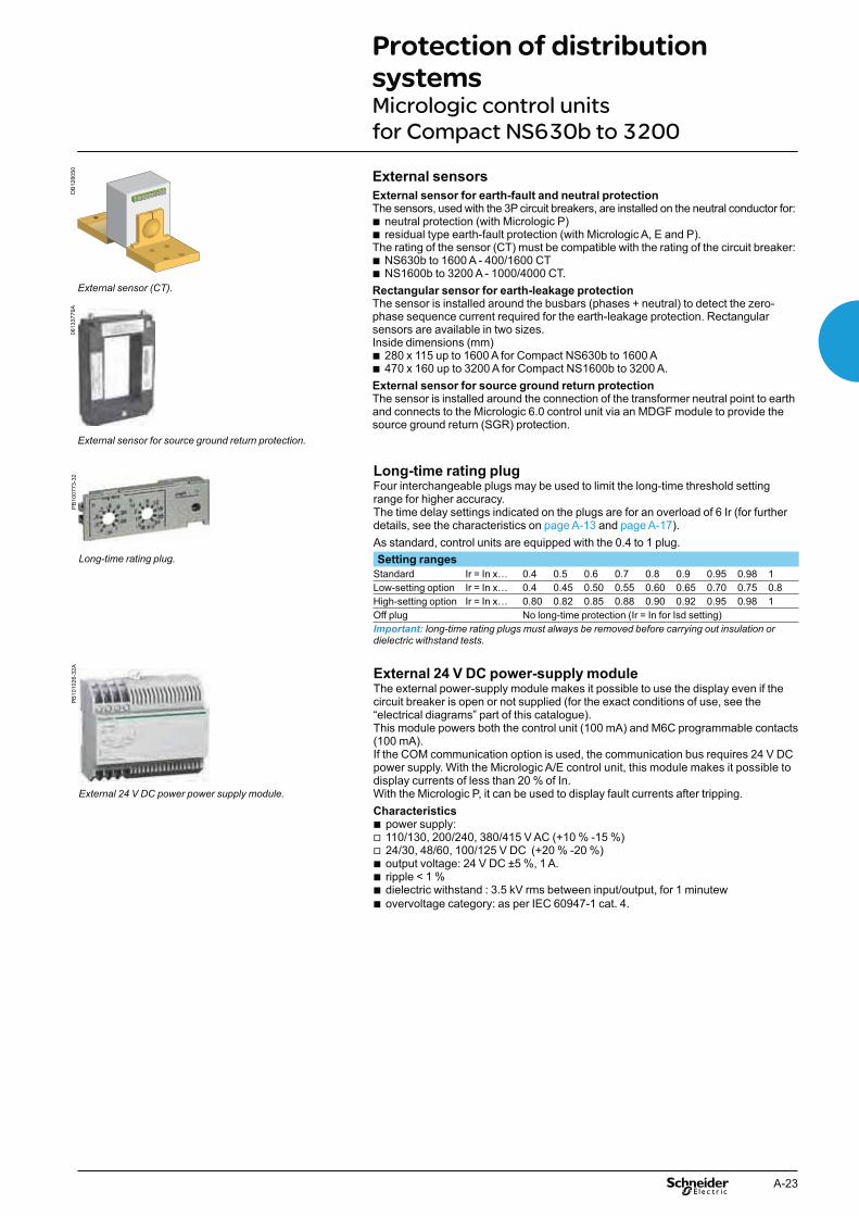
A-23
DB
1280
50
External sensor (CT).
External sensors
External sensor for earth-fault and neutral protectionThe sensors, used with the 3P circuit breakers, are installed on the neutral conductor for:
neutral protection (with Micrologic P) bresidual type earth-fault protection (with Micrologic A, E and P). b
The rating of the sensor (CT) must be compatible with the rating of the circuit breaker:NS630b to 1600 A - 400/1600 CT bNS1600b to 3200 A - 1000/4000 CT. b
Rectangular sensor for earth-leakage protectionThe sensor is installed around the busbars (phases + neutral) to detect the zero-phase sequence current required for the earth-leakage protection. Rectangular sensors are available in two sizes.Inside dimensions (mm)
280 x 115 up to 1600 A for Compact NS630b to 1600 A b470 x 160 up to 3200 A for Compact NS1600b to 3200 A. b
External sensor for source ground return protectionThe sensor is installed around the connection of the transformer neutral point to earth and connects to the Micrologic 6.0 control unit via an MDGF module to provide the source ground return (SGR) protection.
0613
3779
A
External sensor for source ground return protection.
PB
1007
73-3
2 Long-time rating plugFour interchangeable plugs may be used to limit the long-time threshold setting range for higher accuracy. The time delay settings indicated on the plugs are for an overload of 6 Ir (for further details, see the characteristics on page A-13 and page A-17).As standard, control units are equipped with the 0.4 to 1 plug.
Long-time rating plug. Setting ranges
Standard Ir = In x… 0.4 0.5 0.6 0.7 0.8 0.9 0.95 0.98 1Low-setting option Ir = In x… 0.4 0.45 0.50 0.55 0.60 0.65 0.70 0.75 0.8High-setting option Ir = In x… 0.80 0.82 0.85 0.88 0.90 0.92 0.95 0.98 1Off plug No long-time protection (Ir = In for Isd setting)Important: long-time rating plugs must always be removed before carrying out insulation or dielectric withstand tests.
PB
1010
26-3
2A
External 24 V DC power-supply moduleThe external power-supply module makes it possible to use the display even if the circuit breaker is open or not supplied (for the exact conditions of use, see the “electrical diagrams” part of this catalogue).This module powers both the control unit (100 mA) and M6C programmable contacts (100 mA).If the COM communication option is used, the communication bus requires 24 V DC power supply. With the Micrologic A/E control unit, this module makes it possible to display currents of less than 20 % of In. With the Micrologic P, it can be used to display fault currents after tripping. Characteristics
power supply: b110/130, 200/240, 380/415 V AC (+10 % -15 %) v24/30, 48/60, 100/125 V DC (+20 % -20 %) voutput voltage: 24 V DC ±5 %, 1 A. bripple < 1 % bdielectric withstand : 3.5 kV rms between input/output, for 1 minutew bovervoltage category: as per IEC 60947-1 cat. 4. b
External 24 V DC power power supply module.
Protection of distribution systemsMicrologic control units for Compact NS630b to 3200

A-24
PB
1007
71-2
4
Battery moduleThe battery module maintains display operation and communication with the supervisor if the power supply to the Micrologic control unit is interrupted. It is installed in series between the Micrologic control unit and the AD module.Characteristics
battery run-time: 4 hours (approximately) bmounted on vertical backplate or symmetrical rail. b
Battery module.
PB
1007
81-3
2_S
E
M6C.
M6C programmable contacts These contacts are optional equipment for the Micrologic P control units.They are described with the indication contacts for the circuit breakers.Micrologic Type P
Characteristics M6C
Minimum load 100 mA/24 VBreaking capacity (A)p.f.: 0.7
V AC 240 5380 3
V DC 24 1.848 1.5125 0.4250 0.15
M6C: external 24 V DC power supply required (consumption 100 mA).
PB
1007
75-3
2
Lead-seal cover.
Spare parts
Lead-seal covers
A lead-seal cover controls access to the adjustment dials.When the cover is closed:
it is impossible to modify settings using the keypad unless the settings lockout pin bon the cover is removed
the test connector remains accessible bthe test button for the earth-fault and earth-leakage protection function remains b
accessible.Characteristics
transparent cover for basic Micrologic and Micrologic A, E control units bnon-transparent cover for Micrologic P control units. b
Spare battery
A battery supplies power to the LEDs identifying the tripping causes. Battery service life is approximately ten years.A test button on the front of the control unit is used to check the battery condition. The battery may be replaced on site when discharged.
Functions and characteristics Protection of distribution systemsMicrologic control units for Compact NS630b to 3200

A-25
PB
1008
37-6
8
Portable test kit.
Test equipment
Hand-held test kit
The hand-held mini test kit may be used to:check operation of the control unit and the tripping and pole-opening system by b
sending a signal simulating a short-circuitsupply power to the control units for settings via the keypad when the circuit b
breaker is open (Micrologic P control units).Power source: standard LR6-AA battery.Full function test kit
The test kit can be used alone or with a supporting personal computer.The test kit without PC may be used to check:
the mechanical operation of the circuit breaker bthe electrical continuity of the connection between the circuit breaker and b
the control unitoperation of the control unit: bdisplay of settings vautomatic and manual tests on protection functions vtest on the zone-selective interlocking (ZSI) function vinhibition of the earth-fault protection vinhibition of the thermal memory. v
The test kit with PC offers in addition:the test report (software available on request). b

A-26
GetnSet is a portable data acquisition and storage accessory that connects directly to the Micrologic control units of Compact and Masterpact circuit breakers to read important electrical installation operating data and Compact protection settings.This information is stored in the GetnSet internal memory and can be transferred to a PC via USB or Bluetooth for monitoring and analysis.
Overview GetnSet functionsGetnSet(1) is a portable data acquisition and storage device that works like a USB drive, letting users manually transfer data to and from a Compact and Masterpact circuit breakers or PC.GetnSet can download operating data from Compact and Masterpact, and download or upload settings.Downloadable operating data include measurements, the last 3 trip history records and contact wear status.Accessible settings include protection thresholds, external relay assignment modes and pre-defined alarm configurations if applicable.
PB
1040
17
DB
1176
16
On/Off1 batterie indicator2 Download settings3 Download operating parameters4 Upload settings5 USB indicator6 Bluetooth indicator7
DB
1174
40
Operating data functionsElectrical installation information such as energy measurements and contact wear status is increasingly important to help reduce operating expenses and increase the availability of electrical power. Such data is often available from devices within the installation, but needs to be gathered and aggregated to allow analysis and determine effective improvement actions.With GetnSet, this operating data can be easily read and stored as .dgl files in the internal memory. It can then be transferred to a PC via a USB or Bluetooth link and imported in an Excel spreadsheet. The provided Excel spreadsheet can be used to display the operating data from several breakers in order to:
analyse changes in parameters such as energy, power factor and contact wear bcompare the values of parameters between circuit breakers bcreate graphics and reports using standard Excel tools b
GetnSet data accessible in the Excel spreadsheet
Type of data Micrologic
Current A/E PEnergy, voltages, frequency, power, power factor E PPower quality: fundamental, harmonics - -Trip history E PContact wear - P
Functions and characteristics Portable data acquisitionGetnSet

A-27
DB
1174
41
Protection setting functionsGetnSet can also be used to back up circuit breaker settings and restore them on the same device or, under certain conditions, copy them to any Compact and Masterpact circuit breakers equipped with the same type of Micrologic control unit. This concerns only advanced settings, as other parameters must be set manually using the dials on the Micrologic control unit.
When commissioning the installation, safeguard the configuration parameters of byour electrical distribution system by creating a back-up of circuit breaker settings so that they can be restored at any time.
The settings read by GetnSet can be transferred to a PC and are compatible with bRSU software (Remote Setting Utility). Protection configurations can also be created on a PC using this software, copied to GetnSet's internal memory and uploaded to a Compact and Masterpact circuit breakers with a compatible Micrologic trip unit and dial settings.
Operating procedureThe procedure includes several steps.
Plug GetnSet into the receptacle on the front of the Micrologic control unit of ba Compact and Masterpact circuit breakers.
On the keypad, select the type of data (operating data or settings) and the transfer bdirection (download or upload). This operation can be done as many times as required for the entire set of Compact and Masterpact circuit breakers.
Downloaded data is transferred to the GetnSet internal memory and a file is bcreated for each Compact device (either an .rsu file for settings or a.dgl file for operating data).
Data can be transferred between GetnSet and a PC via a USB or Bluetooth bconnection.
Operating data can be imported in an Excel spreadsheet and protection settings bcan be read with RSU (remote setting utility) software.
FeaturesBattery-powered to power a Micrologic control unit even if the breaker has been b
opened or tripped. This battery provides power for an average of 1 hour of use, enough for more than 100 download operations.
Can be used on Compact and Masterpact circuit breakers equipped or not bequipped with a Modbus "device" communication module.
Portable, standalone accessory eliminating the need for a PC to connect to ba Compact and Masterpact circuit breakers.
No driver or software required for GetnSet connection to a PC. bCan be used with many circuit breakers, one after the other. bEmbedded memory sized to hold data from more than 5000 circuit breakers. bSupplied with its battery, a cable for connection to Micrologic trip units, a USB b
cable for connection to a PC and a battery charger.
CompatibilityMicrologic control units A, E, P. bPC with USB port or Bluetooth link and Excel software. b
Technical characteristics
Charger power supply 100 – 240 V; a1 A; 50 – 60 HzCharger power consumption Max 100 WBattery 3.3 V DC; 9 mAh; Li-IonOperating temperature -20 to +60 °CGetnSet dimensions 95 x 60 x 35 mm

A-28
All the Compact devices can be fitted with the communication function thanks to the COM option.Compact uses the Modbus communications protocol for full compatibility with the supervision management systems. An external gateway is available for communication on other networks:Eco COM is limited to the transmission of metering data.It is not used to communicate status and controls.
For fixed devices, the COM option is made up of:a Modbus BCM ULP “device” communication module, installed behind the b
Micrologic control unit and supplied with its set of sensors (OF, SDE ,PF and CH micro switches) its kit for connection to XF and MX1 communicating voltage releases and its COM terminal block (inputs E1 to E6).For drawout devices, the COM option is made up of:
a Modbus BCM ULP “device” communication module, installed behind the bMicrologic control unit and supplied with its set of sensors (OF, SDE, PF and CH micro switches) its kit for connection to XF and MX1 communicating voltage releases and its COM terminal block (inputs E1 to E6).
a “chassis” communication module supplied separately with its set of sensors (CE, bCD and CT contacts) Modbus CCM.Modbus BCM ULP “Device” communication module
This module is independent of the control unit. It receives and transmits information on the communication network. An infra-red link transmits data between the control unit and the communication module.Consumption: 30 mA, 24 V.Modbus CCM “chassis” communication module
This module is independent of the control unit. With Modbus “chassis” communication module, this module makes it possible to address the chassis and to maintain the address when the circuit breaker is in the disconnected position.Consumption: 30 mA, 24 V.
Modbus BCM ULP “Device” communication module. 1 : Hard wire.Modbus CCM “Chassis” communication module (option). 2 : Modbus.OF, SDE, PF and CH micro switches.3 CE, CD and CT contacts.4 XF, MN or MX communicating voltage releases.5 Micrologic control unit.6 COM terminal block (E1 to E6).7
PB
1007
82-2
6
Modbus BCM ULP “device” communication module.
DB
1280
53
PB
1008
02B
-27
Modbus CCM “chassis” communication module.
Functions and characteristics Communication Compact NS630b to 3200 COM option in Compact
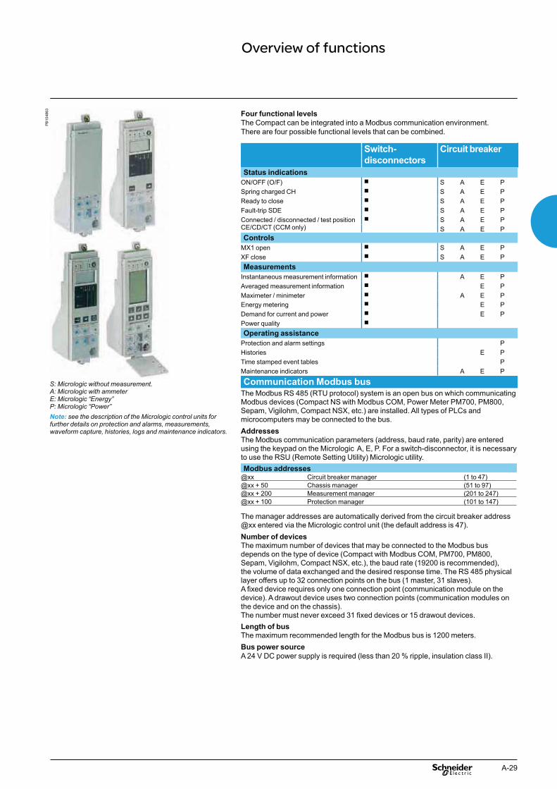
A-29
Overview of functions
PB
1048
63
S: Micrologic without measurement.A: Micrologic with ammeterE: Micrologic “Energy”P: Micrologic “Power”Note: see the description of the Micrologic control units for further details on protection and alarms, measurements, waveform capture, histories, logs and maintenance indicators.
Four functional levels
The Compact can be integrated into a Modbus communication environment. There are four possible functional levels that can be combined.
Switch-
disconnectors
Circuit breaker
Status indications
ON/OFF (O/F) b S A E PSpring charged CH b S A E PReady to close b S A E PFault-trip SDE b S A E PConnected / disconnected / test positionCE/CD/CT (CCM only)
b S A E PS A E P
Controls
MX1 open b S A E PXF close b S A E PMeasurements
Instantaneous measurement information b A E PAveraged measurement information b E PMaximeter / minimeter b A E PEnergy metering b E PDemand for current and power b E PPower quality b
Operating assistance
Protection and alarm settings PHistories E PTime stamped event tables PMaintenance indicators A E P
Communication Modbus bus
The Modbus RS 485 (RTU protocol) system is an open bus on which communicating Modbus devices (Compact NS with Modbus COM, Power Meter PM700, PM800, Sepam, Vigilohm, Compact NSX, etc.) are installed. All types of PLCs and microcomputers may be connected to the bus.Addresses
The Modbus communication parameters (address, baud rate, parity) are entered using the keypad on the Micrologic A, E, P. For a switch-disconnector, it is necessary to use the RSU (Remote Setting Utility) Micrologic utility.Modbus addresses
@xx Circuit breaker manager (1 to 47)@xx + 50 Chassis manager (51 to 97)@xx + 200 Measurement manager (201 to 247)@xx + 100 Protection manager (101 to 147)
The manager addresses are automatically derived from the circuit breaker address @xx entered via the Micrologic control unit (the default address is 47).Number of devices
The maximum number of devices that may be connected to the Modbus bus depends on the type of device (Compact with Modbus COM, PM700, PM800, Sepam, Vigilohm, Compact NSX, etc.), the baud rate (19200 is recommended), the volume of data exchanged and the desired response time. The RS 485 physical layer offers up to 32 connection points on the bus (1 master, 31 slaves).A fixed device requires only one connection point (communication module on the device). A drawout device uses two connection points (communication modules on the device and on the chassis).The number must never exceed 31 fixed devices or 15 drawout devices.Length of bus
The maximum recommended length for the Modbus bus is 1200 meters.Bus power source
A 24 V DC power supply is required (less than 20 % ripple, insulation class II).

A-30
Functions and characteristics Compact communication Networks and sofware
ModbusModbus is the most widely used communication protocol in industrial networks. It operates in master-slave mode. The devices (slaves) communicate one after the other with a gateway (master).Compact, Compact NSX, PowerLogic and Sepam products all operate with this protocol. A Modbus network is generally implemented on an LV or MV switchboard scale. Depending on the data monitored and the desired refresh rate, a Modbus network connected to a gateway can serve 4 to 16 devices. For larger installations, a number of Modbus networks can be connected to an Ethernet network (TCP/IP/Modbus protocol) via their gateways (EGX).
DB
1280
54
Internet
Modbus Modbus
EGX300EGX100
FDM121
Masterpact Compact NSXCompact NS630b/3200
Modbus
PowerMeterSepam
FDM121
FDM121CCM
Firewall
Automaticnotification
Nomadmode
Site Intranet
Ethernet (TCP/IP/Modbus)
ConsultationRSURCU
ConsultationRSURCU
Ethernet (TCP/IP/Modbus)ModbusULP
Compact uses the Modbus communication protocol, compatible with ION-E electrical engineering expert system software. Two downloadable sofware (RSU, RCU) from schneider-electric.com facilitate implementation of communication functions.

A-31
Micrologic utilitiesTwo utilities, RSU and RCU, presented on the next page, are available to assist in b
starting up a communicating installation. Intended for Compact and Compact NSX, the software can be downloaded from the Schneider Electric internet site.
The "Live update" function enables immediate updating to obtain the most recent bupgrades. These easy-to-use utilities include starting assistance and on-line help. They are compatible with Microsoft Windows 2000, XP and Windows 7.
PB
1048
05
RSU configuration screen for a Micrologic.
DB
1122
14
RCU mini-supervision screen for current measurements.
GatewayThe gateway has two functions:
access to the company intranet (Ethernet) by converting Modbus frames to bthe TCP/IP/Modbus protocol
optional web-page server for the information from the devices. bExamples include EGX300 and EGX100.
PE
8618
1r-2
5
EGX300.

A-32
Functions and characteristics Compact communication RSU and RCU utilities
RSU (Remote Setting Utility)This utility is used to set the protection functions and alarms for each Compact and Compact NSX device. After connection to the network and entry of the circuit breaker Modbus address, the software automatically detects the type of trip unit installed.There are two possible operating modes.
Off-line with the software disconnected from the
communication network For each selected circuit breaker, the user can do the following.Determine the protection settings
The settings are carried out on a screen that shows the front of the trip unit. The Micrologic setting dials, keypad and screen are simulated for easy use of all Micrologic setting functions. Save and duplicate the protection settings
Each configuration created can be saved for subsequent device programming. It can also be duplicated and used as the basis for programming another circuit breaker.
On-line with the software connected to the networkSimilarly, for each selected circuit breaker, the user can do the following.Display the current settings
The software displays the trip unit and provides access to all settings.View the corresponding protection curves
A graphic curve module in the software displays the protection curve corresponding to the settings. It is possible to lay a second curve over the first for discrimination studies. Modify settings in a secure manner
There are different levels of security: bpassword: by default, it is the same for all devices, but can be differentiated for v
each devicelocking of the Modbus interface module which must be unlocked before the v
corresponding device can be set remotelymaximum settings limited by the positions of the two dials on the trip unit. v
These dials, set by the user, determine the maximum settings that can be made via the communication system.
Settings are modified by: beither direct, on-line setting of the protection settings on the screen vor by loading the settings prepared in off-line mode. This is possible only if the v
positions of the dials allow the new settings. All manual settings made subsequently on the device have priority.Program alarms
Up to 12 alarms can be linked to measurements or events. btwo alarms are predefined and activated automatically: bMicrologic 5: overload (Ir) vMicrologic 6: overload (Ir) and ground fault (Ig) vthresholds, priorities and time delays can be set for 10 other alarms. They may be b
selected from a list of 91 alarmsSet the outputs of the SDx relays
This is required when the user wants to change the standard configuration and assign different signals to the 2 outputs of the SDx relay.
RCU (Remote Control Utility)The RCU utility can be used to test communication for all the devices connected to the Modbus network. It is designed for use with Compact NSX, Compact, Advantys OTB and Power Meter devices. It offers a number of functions.Mini supervisor
Display of I, U, f, P, E and THD measurements for each device, via navigation. bDisplay of ON/OFF status. b
Open and close commands for each device
A common or individual password must first be entered.
When all functions have been tested, this utility is replaced by the supervision software selected for the installation.
Two utilities, RSU and RCU, are available to assist in starting up a communicating installation.They can be downloaded from the Schneider Electric internet site and include a "Live update" function that enables immediate updating.
DB
1187
23
RCU: Remote Control Utility for communication tests.
PB
1048
05P
B10
4806
RSU: Micrologic Remote Setting Utility.

A-33
Types of softwareMasterpact, Compact and Compact NSX communication functions are designed to interface with software dedicated to electrical installations:
switchboard supervision belectrical installation supervision bpower system management: electrical engineering expert systems bprocess control bSCADA (Supervisory Control & Data Acquisition), EMS (Enterprise Management b
System) or BMS (Building Management System) type software.
Schneider Electric solutions
Electrical switchboard supervision via EGX300 Web serversA simple solution for customers who want to consult the main electrical parameters of switchboard devices without dedicated software. Up to 16 switchboard devices are connected via Modbus interfaces to an EGX300 Ethernet gateway integrating the functions of a web page server. The embedded Web pages can be easily configured with just a few mouse clicks. The information they provide is updated in real time. The Web pages can be consulted using a standard Web browser on a PC connected via Ethernet to the company Intranet or remotely via a modem. Automatic notification of alarms and threshold overruns is possible via e-mail or SMS (Short Message Service).
Electrical installation supervision via iRIO RTUThe iRIO RTU(remote terminal unit) can be used as Ethernet coupler for the PowerLogic System devices and for any other communicating devices operating under Modbus RS 485 protocol. Data is viewable via a standard web browser.
ION-E electrical engineering expert system softwareION-E is a family of web-enabled software products for high-end power-monitoring applications. It is designed for large power systems.ION-E offer detailed analysis of electrical events, long-duration data logging and extensive, economical report-building capabilities (e.g. consumption monitoring and tariff management).A wide variety of screens can be displayed in real time, including more than 50 tables, analogue meters, bargraphs, alarms logs with links to display waveforms and predefined reports on energy quality and service costs.
Other software Masterpact, Compact and Compact NSX devices can forward their measurement and operating information to special software integrating the electrical installation and other technical facilities:
SCADA process control software: Vijeo CITECT bBMS Building Management System software: Vista. b
www.schneider-electric.com
PE
8618
1r-2
5
EGX300
PB
1048
59
iRIO RTU
PB
1048
07_6
8
ION Enterprise Power Management Software
Supervision software
Schneider Electric electrical installation supervision, management and expert system software integrates Compact, Compact NSX and Masterpact identification modules.

A-34
Functions and characteristics Compact communicationCommunication wiring system
Wiring system UPP
The wiring system is designed for low-voltage power switchboards. Installation requires no tools or special skills.The prefabricated wiring ensures both data transmission (ModBus protocol) and 24 V DC power distribution for the communications modules on the Micrologic control units.
PB
1048
03-1
76
1
2
3
4
5
6
7
8 9 4
6
13
12
11
10
1 BCM ULP: Breaker Communication Module with ULP port 12 ULP cable 0.3 m0.6 m1 m2 m3 m5 m
TRV00803TRV00806TRV00810TRV00820TRV00830TRV00850
2 Micrologic control unit3 Breaker ULP cord 0.35 m
1.3 m3 m
LV434195LV434196LV434197
4 Modbus cable5 Ethernet cable 13 NSX cord 0.35 m
1.3 m3 m
LV434200LV434201LV434202
6 FDM121: Front Display Module TRV001217 ULP linel terminators TRV008808 EGX100: Ethernet gateway9 External 24 V DC power supply module10 Modbus interface TRV0021011 Stacking accessorie TRV00217
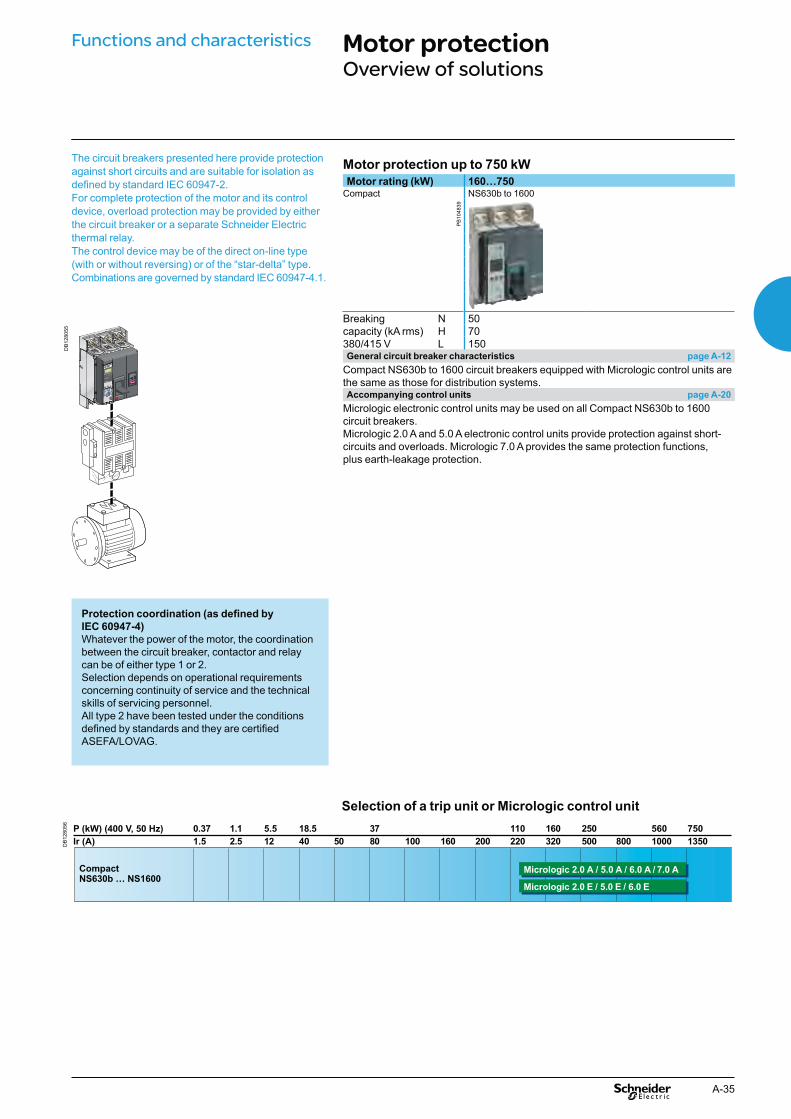
A-35
Motor protection up to 750 kW
Motor rating (kW) 160…750Compact NS630b to 1600
PB
1048
39
Breaking N 50capacity (kA rms) H 70380/415 V L 150General circuit breaker characteristics page A-12
Compact NS630b to 1600 circuit breakers equipped with Micrologic control units are the same as those for distribution systems.Accompanying control units page A-20
Micrologic electronic control units may be used on all Compact NS630b to 1600 circuit breakers.Micrologic 2.0 A and 5.0 A electronic control units provide protection against short-circuits and overloads. Micrologic 7.0 A provides the same protection functions, plus earth-leakage protection.
Motor protectionOverview of solutions
The circuit breakers presented here provide protection against short circuits and are suitable for isolation as defined by standard IEC 60947-2.For complete protection of the motor and its control device, overload protection may be provided by either the circuit breaker or a separate Schneider Electric thermal relay.The control device may be of the direct on-line type (with or without reversing) or of the “star-delta” type.Combinations are governed by standard IEC 60947-4.1.
Protection coordination (as defined by IEC 60947-4)
Whatever the power of the motor, the coordination between the circuit breaker, contactor and relay can be of either type 1 or 2.Selection depends on operational requirements concerning continuity of service and the technical skills of servicing personnel.All type 2 have been tested under the conditions defined by standards and they are certified ASEFA/LOVAG.
DB
1280
55
Functions and characteristics
Selection of a trip unit or Micrologic control unit
DB
1280
56 P (kW) (400 V, 50 Hz)Ir (A)
0.371.5
18.540
5.512 50
3780 100 160 200
110220
160320
250500 800
5601000
7501350
1.12.5
CompactNS630b … NS1600
Micrologic 2.0 A / 5.0 A / 6.0 A / 7.0 A
Micrologic 2.0 E / 5.0 E / 6.0 E

A-36
Circuit breakers equipped with a control unit offering integrated
earth-leakage protection and an external rectangular sensor
Rated current (A) 630… 3200Compact NS630b to 1000 N/L NS1600b to 3200
NS1250 and 1600 N
PB
1048
44_M
E
PB
1048
45_S
E
General circuit breaker characteristics page A-12
Compact NS630b to 3200 circuit breakers are presented in the “Protection of distribution systems” section.Accompanying control units page A-22
Micrologic 7.0 A electronic control units offer earth-leakage protection as standard.
Earth-leakage protection using a Vigirex relay
Earth-leakage relay Separate toroids Rectangular sensors
PB
1004
35_1
6_S
E
0513
52_3
2_S
E
0613
3779
A
Compact circuit breaker + Vigirex relay combination
Vigirex relays may be used to add external earth-leakage protection to Compact NS circuit breakers. The circuit breakers must be equipped with an MN or MX voltage release. Vigirex relays are very useful when special time-delay or tripping-threshold values are required, or when there are major installation constraints (circuit breaker already installed and connected, limited space available, etc.).Vigirex-relay characteristics:
rectangular sensors up to 3200 A b400 Hz distribution systems. b
Options:
trip alarm by a fail-safe contact bpre-alarm LED and contact, etc. b
Compliance with standards:
IEC 60947-2, appendix M bIEC/EN 60755: general requirements for residual current operated protective b
devicesIEC/EN 6100-4-2 to 4-6: immunity tests bCISPR11: radio-frequency radiated and conducted emission tests bUL1053 and CSA22.2 No. 144 for RH10, RH21 and RH99 relays at supply b
voltages up to and including 220/240 V.
Functions and characteristics Earth-leakage protectionOverview of solutions
Earth-leakage protection is obtained by:b installing a Micrologic 7.0 A control unit (Compact NS630b to 3200)b using a Vigirex relay and separate sensors (all Compact circuit breakers).

A-37
Final distribution enclosure for commercial applications
Main power distribution board for commercial applications
Main power distribution board for industrial applications
Control and isolationOverview of solutions
Switch-disconnectors
PB
1043
96_1
7_S
E
0564
70_1
1_S
E
0521
64b-
95
PB
1010
43_1
0
8610
6d
0543
61
Masterpact Compact NS Interpact INS Interlocking Compact NSX Vario NG125
PB
1048
38
PB
1000
20b
0521
68_S
E
PB
1008
40-1
5_S
E
0546
29_7
_SE
0566
52_S
E
Compact NS Interpact IN Interpact INS Source-changeover Multi 9 Interpact INS
DB
4014
68
Circuit breaker-disconnector
Switch-disconnector
Standardised symbols
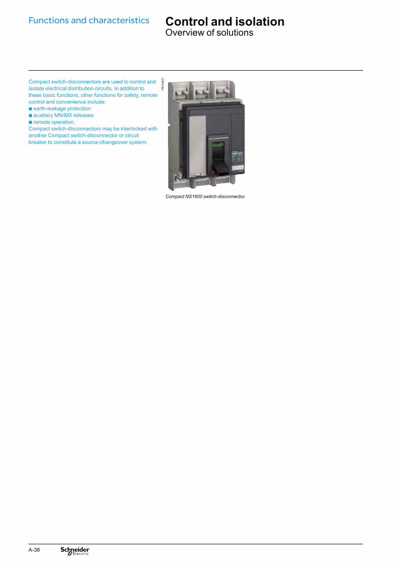
A-38
Compact switch-disconnectors are used to control and isolate electrical distribution circuits. In addition to these basic functions, other functions for safety, remote control and convenience include:b earth-leakage protectionb auxiliary MN/MX releasesb remote operation.Compact switch-disconnectors may be interlocked with another Compact switch-disconnector or circuit breaker to constitute a source-changeover system.
PB
1048
37
Compact NS1600 switch-disconnector.
Functions and characteristics Control and isolationOverview of solutions

A-39

A-40
Functions and characteristics Control and disconnectionCompact NS630bNA to NS1600NA switch-disconnectors
Installation standards require upstream protection.
PB
1048
37
Compact NS800NA.
Functions and characteristics
(1) Suitable for 480 V NEMA.
Compact switch-disconnectorsNumber of poles Control manual toggle
direct or extended rotary handleelectric
Connections fixed front connectionrear connection
withdrawable (on chassis) front connectionrear connection
Electrical characteristics as per IEC 60947-3 and EN 60947-3
Conventional thermal current (A) Ith 60 °CRated insulation voltage (V) Ui
Rated impulse withstand voltage (kV) Uimp
Rated operational voltage (V) Ue AC 50/60 HzRated operational current le AC 50/60 Hz
220/240 V380/415 V440/480 V (1)
500/525 V660/690 V
Short-circuit making capacity lcm (kA peak)Short-time withstand current lcw (A rms) 0.5 s
20 sSuitability for isolationDurability (C-O cycles) mechanical
electrical AC 440 V AC23A/InPositive contact indicationPollution degreeProtection
Add-on earth-leakage protection combination with Vigirex relayAdditional indication and control auxiliaries
Indication contactsVoltage releases MX shunt release
MN undervoltage releaseRemote communication by bus
Device status indications (communicating auxiliary contacts)Device remote operation (communicating motor mechanism)Installation
Accessories terminal extensions and spreadersterminal shields and interphase barriersescutcheons
Dimensions (mm) fixed 3P W x H x D 4PWeight (kg) fixed 3P
4PSource-changeover system (see section "on source-changeover systems")
Manual source-changeover systems, remote-operated and automatic

A-41
NS630bNA NS800NA NS1000NA NS1250NA NS1600NA3, 4 3, 4 3, 4 3, 4 3, 4b b b b bb b b b bb b b b bb b b b bb b b b bb b b b bb b b b b
630 800 1000 1250 1600
800 800 800 800 8008 8 8 8 8690 690 690 690 690AC23A AC23A AC23A AC23A AC23A
630 800 1000 1250 1600630 800 1000 1250 1600630 800 1000 1250 1600630 800 1000 1250 1600630 800 1000 1250 160052 52 52 52 5225 25 25 25 254 4 4 4 4b b b b b10000 10000 10000 10000 100002000 2000 2000 2000 1000b b b b b
3 3 3 3 3
b
bbb
bb
bbb327 x 210 x 147327 x 280 x 1471418
b

A-42
Control and disconnectionCompact NS1600bNA to 3200NA switch-disconnectors
Installation standards require upstream protection. However, Compact NS1600b to 3200NA switch-disconnectors are self-protected for all currents higher than 130 kA peak.
Functions and characteristics P
B10
4838
Compact NS2000NA.
(1) Suitable for 480 V NEMA.
Compact switch-disconnectorsNumber of poles Control manual toggle
direct or extended rotary handleelectric
Connections fixed front connectionrear connection
withdrawable (on chassis) front connectionrear connection
Electrical characteristics as per IEC 60947-3 and EN 60947-3
Conventional thermal current (A) Ith 60 °CRated insulation voltage (V) Ui
Rated impulse withstand voltage (kV) Uimp
Rated operational voltage (V) Ue AC 50/60 HzRated operational current le AC 50/60 Hz
220/240 V380/415 V440/480 V (1)
500/525 V660/690 V
Short-circuit making capacity lcm (kA peak)Short-time withstand current lcw (A rms) 3 sIntegrated instantaneous protection (kA peak ±10 %)Suitability for isolationDurability (C-O cycles) mechanical
electrical AC 440 V AC23A/InPositive contact indicationPollution degreeProtection
Add-on earth-leakage protection combination with Vigirex relayAdditional indication and control auxiliaries
Indication contactsVoltage releases MX shunt release
MN undervoltage releaseInstallation
Accessories escutcheonsDimensions (mm) fixed 3P W x H x D 4PWeight (kg) fixed 3P
4PSource-changeover system (see section "on source-changeover systems")
Manual source-changeover systems, remote-operated and automatic

A-43
NS1600bNA NS2000NA NS2500NA NS3200NA3, 4 3, 4 3, 4 3, 4b b b b- - - -- - - -b b b b- - - -- - - -- - - -
1600 2000 2500 3200800 800 800 8008 8 8 8690 690 690 690AC23A AC23A AC23A AC23A
1600 2000 2500 32001600 2000 2500 32001600 2000 2500 32001600 2000 2500 32001600 2000 2500 3200135 135 135 13532 32 32 32130 130 130 130b b b b6000 6000 6000 60001000 1000 1000 1000b b b b3 3 3 3
b
bb
b
b350 x 420 x 160350 x 535 x 1602336
-

A-44
Source-changeover systemsPresentation
Functions and characteristicsP
B10
0843
Manual source-changeover systemThis is the most simple type. It is controlled manually by an operator and consequently the time required to switch from the normal to the replacement source can vary.A manual source-changeover system is made up of two or three mechanically interlocked manually-operated circuit breakers or switch-disconnectors.
Remote-operated source-changeover systemThis is the most commonly employed system for devices with high ratings (above 400 A). No human intervention is required. Transfer from the normal to the replacement source is controlled electrically.A remote-controlled source-changeover system is made up of two or three circuit breakers or switch-disconnectors linked by an electrical interlocking system that may have different configurations. In addition, a mechanical interlocking system protects against electrical malfunctions or incorrect manual operations.
Automatic source-changeover systemsAn automatic controller may be added to a remote-operated source-changeover system for automatic source control according to programmable operating modes.This solution ensures optimum energy management:
transfer to a replacement source according to external requirements bmanagement of power sources bregulation bemergency source replacement, etc. b
The automatic controller may be fitted with an option for communication with a supervisor.
Communication optionThe communication option must not be used to control the opening or closing of source-changeover system circuit breakers. It should be used only to transmit measurement data or circuit breaker status.The eco COM option is perfectly suited to these equipments.
PB
1008
44
Commercial and service sector:operating rooms in hospitalsb safety systems for tall buildingsb computer rooms (banks, insurance companies, etc.)b lighting systems in shopping centres…
PB
1009
45
Industry:b assembly linesb engine rooms on shipsb critical auxiliaries in thermal power stations…
PB
1008
46P
B10
0847
Infrastructures:b port and railway installationsb runway lighting systemsb control systems on military sites…

A-45
Mechanical interlocking
A manual source-changeover system can be installed on two to three manually-operated circuit breakers or switch-disconnectors. Interlocking is mechanical.Interlocks prevent connection to both sources at the same time, even momentarily.
Interlocking of two devices with rotary handlesThe rotary handles are padlocked with the devices in the OFF position. The mechanism inhibits the two devices being closed at the same time, but does allow for both to be open (OFF) at the same time.Combinations of Normal and Replacement devices
All Compact NS630b to 1600 circuit breakers and switch-disconnectors with rotary handles can be interlocked. Interlocking of a Compact NS630b with a Compact NS630b to 1600 is not possible.
Interlocking of a number of devices using keylocks
(captive keys)Interlocking uses two identical keylocks with a single key. This solution enables interlocking between two devices that are physically distant or that have significantly different characteristics, for example between a low and a medium-voltage device, or between Compact NS circuit breakers and switch-disconnectors.A system of wall-mounted units with captive keys makes possible a large number of combinations between many devices.Combinations of Normal and Replacement devices
All Compact NS630b to 1600 circuit breakers and switch-disconnectors with rotary handles or motor mechanisms can be interlocked.
Interlocking of two Compact NS630b to 1600 devices using
connecting rodsThe two devices must be mounted one above the other (either 2 fixed or 2 withdrawable/drawout devices).Installation
This function requires:an adaptation fixture on the right side of each circuit breaker or switch-disconnector ba set of connecting rods with no-slip adjustments. b
The adaptation fixtures, connecting rods and circuit breakers or switch-disconnectors are supplied separately, ready for assembly by the customer.The maximum vertical distance between the fixing planes is 900 mm.Possible combinations of “Normal” and “Replacement” source circuit
breakers
Combinations are possible between Compact NS630b to NS1600 devices and between Masterpact NT and Masterpact NW devices.
Interlocking of two Compact NS630b to 1600 devices
using cablesFor cable interlocking, the circuit breakers may be mounted one above the other or side-by-side.The interlocked devices may be fixed or drawout, three-pole or four-pole, and have different ratings and sizes.Installation
This function requires:an adaptation fixture on the right side of each device ba set of cables with no-slip adjustments. b
The maximum distance between the fixing planes (vertical or horizontal) is 2000 mm.
Possible combinations of “Normal” and “Replacement” source circuit breakers
“Normal N” “Replacement” R
NS630b to NS1600
NT06 to NT16 NW08 to NW40
NW40b to NW63
NS630b to NS1600
Ratings 250... 1600 A b - - -
It is not possible to combine Compact NS630b to 1600 and Masterpact (NT or NW) devices.
DB
4018
29
Interlocking with keylocks.
DB
4018
30
Interlocking of two devices with rotary handles.
DB
1284
65
OI
O
OI
O
DB
1284
66
OI
O
OI
O
Interlocking with connecting rods
Interlocking with cables

A-46
Source-changeover systemsElectrical interlocking
Electrical interlocking is carried out by an electrical control device.For Compact NS630b to 1600, this function can be implemented in one of two ways:
using the IVE unit bby an electrician in accordance with the chapter "Electrical Diagrams" of the b
catalogue source-changeover system.
Characteristics of the IVE unitexternal connection terminal block: binputs: circuit breaker control signals voutputs: status of the SDE contacts on the “Normal” and “Replacement” source v
circuit breakers2 connectors for the two “Normal” and “Replacement” source circuit breakers: binputs: v
- status of the OF contacts on each circuit breaker (ON or OFF)- status of the SDE contacts on the “Normal” and “Replacement” source circuit breakers
outputs: power supply for operating mechanisms vcontrol voltage: b24 to 250 V DC v48 to 415 V 50/60 Hz - 440 V 60 Hz. v
The IVE unit control voltage must be same as that of the circuit breaker operating mechanisms.
Electrical interlocking is used with a mechanical interlocking system. An automatic controller may be added to take into account information from the distribution system.
Moreover, the relays controlling the “normal”
and “replacement” circuit breakers must be
mechanically and/or electrically interlocked to
prevent them from giving simultaneous
closing commands.
Necessary equipment
For Compact NS630b to 1600, each circuit breaker must be equipped with:
a motor mechanism ban available OF contact ba CE connected-position contact (carriage switch) on withdrawable circuit b
breakersan SDE contact. b
DB
1280
58
IVE unit.
DB
1109
03
Standard configuration for Compact NSTypes of mechanical interlocking Possible combinations Typical electrical diagrams Diagram no.2 devices
QN QR Compact NS630b to 1600:
0 0 b electrical interlocking with lockout after fault:1 0 v permanent replacement source (without IVE) 51201180
0 1 v with EPO by MX (without IVE) 51201181
v with EPO by MN (without IVE) 51201182
v permanent replacement source (with IVE) 51201183
v with EPO by MX (with IVE) 51201184
v with EPO by MN (with IVE) 51201185
b automatic control without lockout after fault:v permanent replacement source (without IVE) 51201186
Functions and characteristics

A-47
Remote-operated systems
Switching between sources can be automated by adding:1 ACP control plate2 BA or UA controller, or an electrical system provided by the installer for NS630b to 1600.
Electrical system example: part no. 51156904 and 51156904 in the source-changeover system catalogue.
Source-changeover system with a controllerIn this case, changeovers between the Normal and Replacement sources under predefined conditions are initiated by a Schneider Electric controller.
PB
1008
57_1
6_S
E
Control plate.
PB
1008
56_1
5_S
E
Controller.
E32
700
R
N
N
0,5s
R
0,5s
UN
ON / I
OFF / O
fault
UR
ON / I
OFF / O
fault
UN = O
UN = 1
MERLIN GERIN
stop
manu
N
test
R
R
N
N
R
auto
stop
manu
UN
ON / I
OFF / O
fault
UR
ON / I
OFF / O
fault
UN = O
UN = 1
MERLIN GERIN
rotareneg
N
R
test
UB
S
12
DB
1284
65
OI
O
OI
O
DB
1284
66
OI
O
OI
O
Interlocking by rods. Interlocking by cables.

A-48
Source-changeover systemsAssociated controllers
By combining a remote-operated source-changeover system with an integrated BA or UA automatic controller, it is possible to automatically control source transfer according to user-selected sequences.These controllers can be used on source-changeover systems comprising 2 circuit breakers.For source-changeover systems comprising 3 circuit breakers, the automatic control diagram must be prepared by the installer as a complement to to diagrams provided in the “electrical diagrams” section of this catalogue.
PB
1008
55_S
E
BA controller.
PB
1008
56_S
E
UA controller
Controller BA UA
4-position switchCompatible circuit breaker All Compact NS circuit breakerAutomatic operation b b
Forced operation on "Normal" source b b
Forced operation on "Replacement" source b b
Stop (both Normal and Replacement sources OFF) b b
Automatic operationMonitoring of the "Normal" source and automatic transfer b b
Generator set startup control b
Delayed shutdown (adjustable) of engine generator set b
Load shedding and reconnection of non-priority circuits b
Transfer to the “Replacement” source if one of the phases of the “Normal” phase is absent
b
TestBy opening the P25M circuit breaker supplying the controller b
By pressing the test button on the front of the controller b
IndicationsCircuit breaker status indication on the front of the controller:on, off, fault trip
b b
Automatic mode indication contact b b
Other functionsSelection of type of "Normal" source(single-phase or three-phase) (1)
b
Voluntary transfer to "Replacement" source(e.g. energy-management commands)
b b
During peak-tariff periods (energy-management commands)forced operation on "Normal" source if "Replacement" sourcenot operational
b
Additional control contact (not in controller).Transfer to "Replacement" source only if contact closed(e.g. used to test the frequency of UR)
b b
Setting of maximum startup time for the replacement source b
OptionsCommunication option b
Power supplyControl voltages (2) 110 V b b
220 to 240 V 50/60 Hz b b
380 to 415 V 50/60 Hz b b
440 V 60 Hz b b
Operating thresholdsUndervoltage 0.35 Un y voltage y 0.7 Un b b
Phase failure 0.5 Un y voltage y 0.7 Un b
Voltage presence voltage u 0.85 Un b b
IP degree of protection (EN 60529) and IK degree of protection against
external mechanical impacts (EN 50102)Front IP40 b b
Side IP30 b b
Connectors IP20 b b
Front IK07 b b
Characteristics of output contacts (dry, volt-free contacts)Rated thermal current (A) 8Minimum load 10 mA at 12 VOutput contacts: Position of the Auto/Stop switch
b b
Load shedding and reconnection order b
Generator set start order b
AC DCUtilisation category (IEC 60947-5-1) AC12 AC13 AC14 AC15 DC12 DC13Operational current (A) 24 V 8 7 5 6 8 2
48 V 8 7 5 5 2 -110 V 8 6 4 4 0.6 -220/240 V 8 6 4 3 - -250 V - - - - 0.4 -380/415 V 5 - - - - -440 V 4 - - - - -660/690 V - - - - - -
(1) For example, 220 V single-phase or 220 V three-phase.(2) The controller is powered by the ACP control plate. The same voltage must be used for the ACP plate, the IVE unit and the operating mechanisms. If this voltage is the same as the source voltage, then the “Normal” and “Replacement” sources can be used directly for the power supply. If not, an isolation transformer must be used.

A-49

A-50
Connection kitfor connectors
Sealable terminalshield
Electrical control withmixed connection
I on
deppirt
teser
0 OFF
I on
deppirt
teser
0 OFF
Auxiliary contact
Vertical connectionadapter
Sealable terminalshield
Voltage release
Terminal extension forcables with lugs
Connection kitfor connectors
Manual control withfront connection
Spreader
Escutcheon
Extended rotaryhandle
Direct rotaryhandle
Communicationsmodule
Spreader
Interphase barriers
Rear connectors
Manual control withrear connection
Phasebarriers
Phasebarriers
Phasebarriers
NS 1200 H
I
O
35210
O
Functions and characteristics Electrical and mechanical accessoriesCompact NS630b to 1600 (fixed version)
DB
1280
62

A-51
Compact NS630b to 1600 (withdrawable version)
DB
1280
35
Electrical operation
Chassis with front orrear connection
Transparent cover
I on
deppirt
teser
0 OFF
I on
deppirt
teser
0 OFF
Auxiliary contact
Vertical connectionadapter
Voltage release
Terminal extension forcables with lugs
Spreader
Escutcheon
Extended rotaryhandle
Direct rotaryhandle
Communicationsmodule
Spreader
Interphase barriers
Rear connectors
Manual operation
NS 1200 H
NS 1200 H
I
O
35210
O

A-52
Installation
Fixed configurationCompact NS630b to 1600 circuit breakers may be installed vertically, horizontally or flat on their back.
Withdrawable configurationCompact NS630b to 1600 circuit breakers should be installed vertically only.
Electrical and mechanical accessoriesCompact NS630b to 1600
The withdrawable configuration makes it possible to:b extract and/or rapidly replace the circuit breaker without having to touch connections;b allow for the addition of future circuits at a later date.
Functions and characteristicsP
B10
3391
_39_
SE
Fixed Compact NS800.
DB
1280
3405
9782
N_I
_50_
SE
_ME
Withdrawable Compact NS800H.
DB
1280
69
DB
1280
63
Mounting on a backplate.
DB
1280
64
Mounting on rails.
DB
1280
65
Mounting on a backplate.
DB
1280
66
Rear mounting on rails.
DB
1280
67
Device on mounting plate.
DB
1280
68
Device on rails.

A-53
The multifunctional chassis for Compact NS630b to 1600 devices is particularly suited for incoming circuit breakers. Features include:
device connection and disconnection through a door, using a crank that can be bstored in the chassis
three positions (connected, test and disconnected) that are indicated: blocally by a position indicator vremotely by carriage switches (3 for the connected position, 2 for the disconnected v
position and 1 for the test position)circuit breaker ON/OFF commands through a switchboard front panel. b
Locking
There are extensive locking possibilities:chassis locking in connected, disconnected and test positions using three b
padlocks and two keylocks, on the switchboard front paneldoor interlock (inhibits door opening with breaker in connected position) bracking interlock (inhibits racking with door open) blocking in each of the connected, disconnected and test positions during device b
connection or disconnection. Continuation to the next position requires pressing a release button to free the crank.Other safety function
Mismatch protection ensures that a circuit breaker is installed only in a chassis with compatible characteristics.
The device may be in one of four positions on the chassis:b connected position. The power circuits and auxiliary contacts are all connectedb test position. The power circuits are disconnected. The auxiliary contacts are still connected and the device can be operated electricallyb disconnected position. The power circuits and auxiliary contacts are all disconnected, however the device is still mounted on the chassis. It can be operated manually (ON, OFF, "push to trip").b removed position. All circuits are disconnected. The device simply rests on the chassis rails and can be removed.
mismatch protection1 door interlock2 racking interlock3 keylock locking4 padlock locking5 position indicator6 chassis front plate (accessible with cubicle door closed)7 crank entry8 reset button9 crank storage10
DB
1280
70
Connected Test Disconnected Removed
DB
1280
71
1
2
8
10
9
7
5
6
4
3

A-54
Electrical and mechanical accessoriesCompact NS630b to 1600 (cont.)
Types of connection
Fixed device
Front connections (N, L) Connection by:
bars bare cables (except L) cables with lugs
Rear connections (N, L, LB) Connection by:
Horizontal: Vertical: bars cables with lugs
Simply turn a horizontal rear connector 90° to make it a vertical connector.
Combination of front and rear connections (N, L) Connection by:
bars bare cables (except L) cables with lugs
Withdrawable device
Front connections Connection by:
bars cables with lugs
Rear connections Connection by:
bars cables with lugs
Functions and characteristicsD
B12
8077
DB
1280
72
DB
1280
73
DB
1280
74
DB
1280
75
DB
1280
76
DB
1280
78
DB
1280
79
DB
1280
74
DB
1280
72
DB
1280
80
DB
1280
81
DB
1280
82
DB
1280
72
DB
1280
73
DB
1280
74
DB
1280
75
DB
1280
76
DB
1280
83
DB
1280
72
DB
1280
74D
B12
8076
DB
1280
84
DB
1124
81
DB
1124
84D
B12
8080
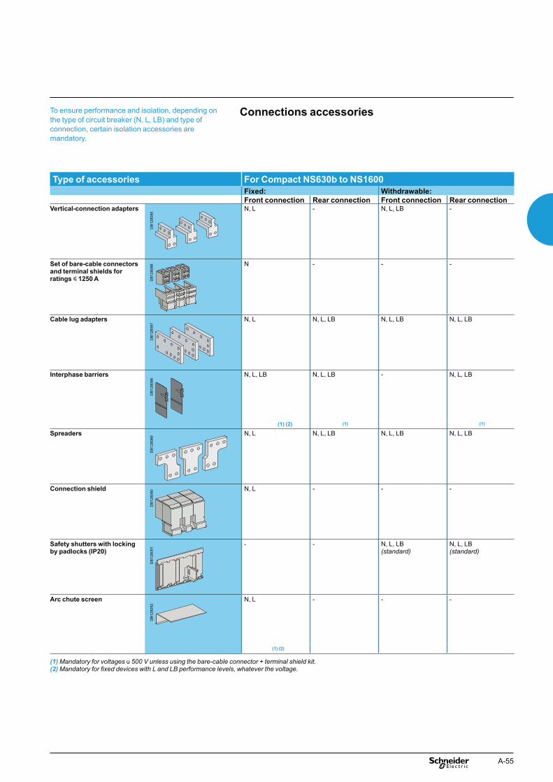
A-55
Connections accessoriesTo ensure performance and isolation, depending on the type of circuit breaker (N, L, LB) and type of connection, certain isolation accessories are mandatory.
Type of accessories For Compact NS630b to NS1600
Fixed: Withdrawable:
Front connection Rear connection Front connection Rear connectionVertical-connection adapters N, L - N, L, LB -
Set of bare-cable connectors and terminal shields for ratings y 1250 A
N - - -
Cable lug adapters N, L N, L, LB N, L, LB N, L, LB
Interphase barriers N, L, LB N, L, LB - N, L, LB
(1) (2) (1) (1)
Spreaders N, L N, L, LB N, L, LB N, L, LB
Connection shield N, L - - -
Safety shutters with locking by padlocks (IP20)
- - N, L, LB(standard)
N, L, LB(standard)
Arc chute screen N, L - - -
(1) (2)
(1) Mandatory for voltages u 500 V unless using the bare-cable connector + terminal shield kit. (2) Mandatory for fixed devices with L and LB performance levels, whatever the voltage.
DB
1280
85D
B12
8092
DB
1280
91D
B12
8090
DB
1280
89D
B12
8088
DB
1280
87D
B12
8086

A-56
Electrical and mechanical accessoriesCompact NS630b to 1600 (cont.)
Fixed, front-connection Compact NS630b to 1600 devices are equipped with terminals comprising captive screws for direct connection of bars.Other connection possibilities for bars include vertical-connection adapters for edgewise bars and spreaders to increase the pole pitch to 95 mm.If the vertical connection adapters are front oriented, then it is mandatory to install the arc chute screen in order to comply with the safety clearances.
Bare cablesSpecial sets of connectors and terminal shields may be used to connect up to four 240 mm2 copper or aluminium cables for each phase. Bare cable connection is possible for ratings up to and including 1250 A.
Cables with lugsCable lug adapters are combined with the vertical-connection adapters.One to four cables with crimped lugs (y 300 mm2) may be connected.To ensure stability, spacers must be positioned between the terminal extensions.If the cable lug adapters are installed over the top of the arc chute chambers, then it is mandatory to install the arc chute screen in order to comply with the safety clearances.
Front connection of fixed devices Bars
Functions and characteristicsD
B12
8093
DB
1280
94
DB
1280
97
Vertical-connection adapters.
DB
1281
00
Spreaders.
DB
1280
98
DB
1280
99
DB
1281
01
DB
1281
02
DB
1281
04D
B12
8106
DB
1281
07 DB
1281
08D
B12
8103
4-cable connectors.
DB
1281
05
Cable lug adapters.
DB
1280
96D
B12
8095

A-57
Rear connection of fixed devicesBarsFixed, rear-connection Compact NS630b to 1600 devices equipped with horizontal or vertical connectors may be directly connected to flat or edgewise bars, depending on the position of the connectors.Spreaders are available to increase the pole pitch to 95 mm.
Cables with lugsCable lug adapters enable connection of one to four cables with crimped lugs (y 300 mm2).To ensure stability, spacers must be positioned between the terminal extensions.
DB
1281
00
Spreaders.
DB
1281
05
Cable lug adapters.
DB
1280
94D
B12
8096
DB
1281
09
DB
1281
10
DB
1281
11
DB
1281
12D
B12
8113
DB
1281
14

A-58
Electrical and mechanical accessoriesCompact NS630b to 1600 (cont.)
Front connection of withdrawable devices
BarsWithdrawable, front-connection Compact NS630b to 1600 devices are suitable for direct connection of bars.Other connection possibilities for bars include vertical-connection adapters for edgewise bars and spreaders to increase the pole pitch to 95 mm.
Cables with lugsCable lug adapters enable connection of one to four cables with crimped lugs (y 300 mm2).To ensure stability, spacers must be positioned between the terminal extensions.
Functions and characteristics
DB
1280
94D
B12
8096
DB
1281
05
Cable lug adapters.
DB
1281
00
Spreaders.
DB
1280
97
Vertical-connection adapters.DB
1281
15
DB
1281
16
DB
1281
17D
B12
8118
DB
1281
19
DB
1281
20

A-59
Rear connection of withdrawable devices
BarsWithdrawable, rear-connection Compact NS630b to 1600 devices equipped with horizontal or vertical connectors may be directly connected to flat or edge-wise bars, depending on the position of the connectors.Spreaders are available to increase the pole pitch to 95 mm.
Cables with lugsCable lug adapters enable connection of one to four cables with crimped lugs (y 300 mm2).To ensure stability, spacers must be positioned between the terminal extensions.
DB
1280
94
DB
1281
21
DB
1281
05
Cable lug adapters.
DB
1281
00
Spreaders.
DB
1280
96
DB
1281
22
DB
1281
23
DB
1281
24D
B12
8125
DB
1281
26

A-60
Electrical and mechanical accessoriesCompact NS630b to 1600 (cont.)
Insulation of live parts
Connection shieldMounted on fixed, front-connection devices, this shield insulates power-connection points, particularly when cables with lugs are used
Interphase barriersThese barriers are flexible insulated partitions used to reinforce isolation of connection points in installations with busbars, whether insulated or not.Barriers are installed vertically between front or rear connection terminals.They are mandatory for voltages u 500 V for both fixed and withdrawable products and for L and LB types, whatever the voltage.
Safety shutters (standard)Mounted on the chassis, the safety shutters automatically block access to the disconnecting contact cluster when the device is in the disconnected or test positions (degree of protection IP20). When the device is removed from its chassis, no live parts are accessible.The shutters can be padlocked (padlock not supplied) to:
prevent connection of the device block the shutters in the closed position. b
Functions and characteristicsE
4519
0
Compact NS equipped with connection shield.
DB
1281
27
Connection shield.
DB
1281
28
Interphase barriers for fixed device, front connection.
DB
1281
29
Interphase barriers for fixed device, rear connection.
DB
1281
30
Interphase barriers for withdrawable device, rear connection.
DB
1281
31
Safety shutters.

A-61
Connection of electrical auxiliaries
Fixed devicesConnections are made directly to the auxiliaries once the front has been removed. Wires exit the circuit breaker through a knock-out in the top.
Withdrawable devicesAuxiliary circuits are connected to terminal blocks located in the top part of the chassis.The auxiliary terminal block is made up of a fixed and moving part. The two parts are in contact when the device is in the test and connected positions.
DB
1281
32 CAF1CAF2CAO1CAO2
OF1OF2OF3SDMN or MX
SDE
COM
Manually operated device.
DB
1281
34
SDEOF3OF2OF1
MN or MX
COM
Electrically operated device.
DB
1281
36
CD2CD1
CT1
CE3CE2CE1
Withdrawable device.
DB
1281
33D
B12
8135

A-62
Electrical and mechanical accessoriesCompact NS630b to 1600 (cont.)
Indication contacts
Contacts installed in the deviceChangeover contacts are used to remote circuit breaker status information and can thus be used for indications, electrical locking, relaying, etc.They comply with the IEC 60947-5 international recommendation.Functions
OF (ON/OFF) - indicates the position of the main circuit breaker contacts bSD (trip indication) - indicates that the circuit breaker has tripped due to: ban overload va short-circuit van earth-leakage fault. voperation of a voltage release voperation of the "push to trip" button vdisconnection when the device is ON. v
Returns to de-energised state when the circuit breaker is reset.SDE (fault indication) - indicates that the circuit breaker has tripped due to: ban overload va short-circuit van earth-leakage fault. v
Returns to de-energised state when the circuit breaker is reset.CAF / CAO (early-make or early-break function) - indicates the position of the b
rotary handle. Used in particular for advanced opening of safety trip devices (early break) or to energise a control device prior to circuit breaker closing (early make).Installation
OF, SD and SDE functions - a single type of contact provides all these different bindication functions, depending on where it is inserted in the device. The contacts clip into slots behind the front cover of the circuit breaker
CAF / CAO function - the contact fits into the rotary-handle unit (direct or bextended).
Electrical characteristics of the OF/SD/SDE/CAF/CAO auxiliary contacts
Contacts Standard Low levelRated thermal current (A) 6 5Minimum load 100 mA at 24 V 1 mA at 4 V Utilisation cat. (IEC 60947-5-1) AC12 AC15 DC12 DC14 AC12 AC15 DC12 DC14Operational 24 V 6 6 6 1 5 3 5 1current (A) 48 V 6 6 2.5 0.2 5 3 2.5 0.2
110 V 6 5 0.6 0.05 5 2.5 0.6 0.05220/240 V 6 4 - - 5 2 - -250 V - - 0.3 0.03 5 - 0.3 0.03380/440 V 6 2 - - 5 1.5 - -480 V 6 1.5 - - 5 1 - -660/690 V 6 0.1 - - - - - -
Connected, disconnected, test position carriage switchesA single type of changeover contact can be mounted optionally on the chassis to indicate, depending on the slot where it is installed:
the connected (CE) position bthe disconnected (CD) position. This position is indicated when the required b
clearance for isolation of the power and auxiliary circuits is reachedthe test (CT) position. In this position, the power circuits are disconnected and the b
auxiliary circuits are connected.Installation
contacts for the connected (CE), disconnected (CD) and test (CT) positions clip binto the upper front section of the chassis.
Electrical characteristics of the CE/CD/CT auxiliary contacts
Contacts Standard Low levelRated thermal current (A) 8 5Minimum load 100 mA at 24 V 2 mA at 15 V Utilisation cat. (IEC 60947-5-1) AC12 AC15 DC12 DC14 AC12 AC15 DC12 DC14Operational 24 V 8 6 2.5 1 5 3 5 1current (A) 48 V 8 6 2.5 0.2 5 3 2.5 0.2
110 V 8 5 0.8 0.05 5 2.5 0.8 0.05220/240 V 8 4 - - 5 2 - -250 V - - 0.3 0.03 5 - 0.3 0.03380/440 V 8 3 - - 5 1.5 - -660/690 V 6 0.1 - - - - - -
All the auxiliary contacts opposite are also available in "low-level" versions capable of switching very low loads (e.g. for the control of PLCs or electronic circuits).
Functions and characteristics05
4549
-18
OF, SD and SDE changeover contacts.
0564
56
Carriage switches for connected (CE), disconnected (CD) and test (CT) positions.

A-63
Rotary handlesThere are two types of rotary handle:
direct rotary handle bextended rotary handle. b
There are two models:standard with a black handle bVDE with a red handle and yellow front for machine-tool control. b
Direct rotary handleDegree of protection IP40, IK07.The direct rotary handle maintains:
visibility of and access to trip unit settings bsuitability for isolation bindication of the three positions O (OFF), I (ON) and tripped baccess to the "push to trip" button bcircuit breaker locking capability in the OFF position by one to three padlocks, b
shackle diameter 5 to 8 mm (not supplied).It replaces the circuit breaker front cover.Accessories transform the standard direct rotary handle for the following situations:
a higher degree of protection (IP43, IK07) bmachine-tool control, complying with CNOMO E03.81.501, IP54, IK07. b
Extended rotary handleDegree of protection IP55, IK07.This handle makes it possible to operate circuit breakers installed at the back of switchboards, from the switchboard front.It maintains:
suitability for isolation bindication of the three positions O (OFF), I (ON) and tripped baccess to trip unit settings, when the switchboard door is open bcircuit breaker locking capability in the OFF position by one to three padlocks, b
shackle diameter 5 to 8 mm (not supplied).The door cannot be opened if the circuit breaker is ON or locked.The extended rotary handle is made up of:
a unit that replaces the front cover of the circuit breaker (secured by screws) ban assembly (handle and front plate) on the door that is always secured in the b
same position, whether the circuit breaker is installed vertically or horizontallyan extension shaft that must be adjusted to the distance. The min/max distance b
between the back of circuit breaker and door is 218/605 mm.
M6C programmable contactsThese contacts, used with the Micrologic P control units, may be programmed via the control unit keypad or via a supervisory station with the COM communication option. They require an external power supply module.They indicate:
the type of fault binstantaneous or delayed threshold overruns. b
They may be programmed:with instantaneous return to the initial state bwithout return to the initial state bwith return to the initial state following a delay. b
Characteristics M6CMinimum load 100 mA/24 V Breaking capacity (A) V AC 240 5p.f.: 0.7 380 3
V DC 24 1.848 1.5125 0.4250 0.15
M6C: external 24 V DC power supply required (consumption 100 mA).
PB
1007
81-3
2_S
E
M6C programmable contacts: circuit breaker external relay with six independent changeover contacts controlled from the circuit breaker via a three-wire connection (maximum length is 10 meters).
PB
1048
28
Compact NS with a direct rotary handle.
PB
1048
29
Compact NS with an extended rotary handle.
DB
1011
70 1 3 222416181012469
5 20148211
7

A-64
Electrical and mechanical accessoriesCompact NS630b to 1600 (cont.)
Manually operated circuit breakers may be equipped with an MX shunt release, an MN undervoltage release or a delayed undervoltage release (MN + delay unit).Electrically operated circuit breakers are equipped as standard with a remote-operating mechanism to remotely open or close the circuit breaker. An MX shunt release or an MN undervoltage release (instantaneous or delayed) may be added.
MX voltage release.
Remote trippingThis function opens the circuit breaker via an electrical order. It is made up of:
a shunt release (2 b nd MX)or an undervoltage release MN bor a delayed undervoltage release MN + delay unit. b
These releases (2nd MX or MN) cannot be operated by the communication bus.The delay unit, installed outside the circuit breaker, may be disabled by an emergency OFF button to obtain instantaneous opening of the circuit breaker.Wiring diagram for the remote-tripping function
Voltage releases 2nd MXWhen energised, the 2nd MX voltage release instantaneously opens the circuit breaker. A continuous supply of power to the 2nd MX locks the circuit breaker in the OFF position.
CharacteristicsPower supply V AC 50/60 Hz 24 - 48 - 100/130 - 200/250 - 277 - 380/480
V DC 12 - 24/30 - 48/60 - 100/130 - 200/250 Operating threshold 0.7 to 1.1 UnPermanent locking function 0.85 to 1.1 UnConsumption (VA or W) pick-up: 200 (200 ms) hold: 4.5Circuit breaker response 50 ms ±10time at Un
Instantaneous voltage releases MNThe MN release instantaneously opens the circuit breaker when its supply voltage drops to a value between 35 % and 70 % of its rated voltage. If there is no supply on the release, it is impossible to close the circuit breaker, either manually or electrically. Any attempt to close the circuit breaker has no effect on the main contacts. Circuit breaker closing is enabled again when the supply voltage of the release returns to 85 % of its rated value.
CharacteristicsPower supply V AC 50/60 Hz 24 - 48 - 100/130 - 200/250 - 380/480
V DC 24/30 - 48/60 - 100/130 - 200/250 Operating opening 0.35 to 0.7 Unthreshold closing 0.85 UnConsumption (VA or W) pick-up: 200 (200 ms) hold: 4.5MN consumption pick-up: 400 (200 ms) hold: 4.5with delay unit (VA or W)Circuit breaker response 90 ms ±5 time at Un
MN delay unitsTo eliminate circuit breaker nuisance tripping during short voltage dips, operation of the MN release can be delayed. This function is achieved by adding an external delay unit in the MN voltage-release circuit. Two versions are available, adjustable and non-adjustable.Characteristics
Power supply non-adjustable 100/130 - 200/250V AC 50-60 Hz /DC adjustable 48/60 - 100/130 - 200/250 - 380/480Operating threshold opening 0.35 to 0.7 Un
closing 0.85 UnConsumption of delay pick-up: 200 (200 ms) hold: 4.5unit alone (VA or W)Circuit breaker response non-adjustable 0.25 stime at Un adjustable 0.5 s - 0.9 s - 1.5 s - 3 s
Functions and characteristics
DB
1281
37
C2
C1
MX
Openingorder
DB
1281
38
Openingorder
D2
D1
MN
DB
1281
39
MN
D2
D1
10 12
3 6
Delayedopeningorder
Instantaneousopeningorder
Delayunit
0564
21

A-65
Electrically operated circuit breakerThe motor mechanism module is used to remotely open and close the circuit breaker. It is made up of a spring-charging motor equipped with an opening release and a closing release.An electrical operation function is generally combined with:
device ON/OFF indication OF b"fault-trip" indication SDE. b
Motor mechanism modulePower supply V AC 50/60 Hz 48/60 - 100/130 - 200/240 - 277 - 380/415
V DC 24/30 - 48/60 - 100/125 - 200/250 Operating threshold 0.85 to 1.1 UnConsumption (VA or W) 180Motor overcurrent 2 to 3 In for 0.1 secondCharging time maximum 4 secondsOperating frequency maximum 3 cycles per minute
Electrical closing order
The release remotely closes the circuit breaker if the spring mechanism is charged.Release electrical characteristics are identical to those of an MX release (see above), the operating threshold is from 0.85 to 1.1 Un and the circuit breaker response time at Un is 60 ms ±10.The Compact NS electrical operation function can be used to implement a synchro-coupling system.Electrical opening order
The release instantaneously opens the circuit breaker when energised. The supply can be impulse-type or maintained.Release electrical characteristics are identical to those of an MX release (see above).
Electrically operated circuit breakers are equipped as standard with a motor mechanism module. Two solutions are available for electrical operation:b a point-to-point solutionb a bus solution with the COM communication option.
In the event of simultaneous opening and closing orders, the mechanism discharges without any movement of the main contacts.In the event of maintained opening and closing orders, the standard electrical operation solution provides an anti-pumping function by blocking the main contacts in open position.
Wiring diagram of a point-to-point electrical operation solution
PB
1048
31
Electrically operated Compact NS circuit breaker.
DB
1281
40
A2 B4
A1
A4
OF
COM
SDE
Closingorder
Openingorder
Supervisor
Motormechanismmodule
DB
1281
41
12 14
11
OF1
82 84
81
SDE
B4
A1
A2A4
ClosedOpenFaultClosingorder
Openingorder
Motormechanismmodule
Wiring diagram of a bus-type electrical operation
solution

A-66
PB
1043
65A
-32
OFF position locking using a keylock and padlocks.
Toggle locked by removable padlocking device.
Locking on manually operated devicesLocking in the OFF position guarantees isolation as per IEC 60947-2.Padlocking systems can receive up to three padlocks with shackle diameters ranging from 5 to 8 mm (padlocks not supplied).Control device Function Means Required
accessoriesToggle lock in
b OFF position padlock removable device
b OFF or ON position padlock fixed deviceDirect rotary handle lock in
b OFF position padlock
b OFF or ON position keylock locking device + keylock
CNOMO direct rotary handle lock inb OFF position padlock
Extended rotary handle lock in OFF position, padlockdoor opening prevented keylock keylock
Locking in ON position does not prevent the device from tripping in the event of a fault or remote tripping order.
Locking on electrically operated devices
Pushbutton locking VBPThe transparent cover blocks access to the pushbuttons used to open and close the device.It is possible to independently lock the opening OFF button and the closing ON button.The pushbuttons may be locked using either:
three padlocks (not supplied) blead seal btwo screws. b
Device locking in the OFF position
VCPO by padlocks, VSPO by keylocksThe circuit breaker is locked in the OFF position by physically maintaining the opening pushbutton pressed down:
using padlocks in standard (one to three padlocks, not supplied) busing a keylock (supplied). b
Keys may be removed only when locking is effective (Profalux or Ronis type locks). The keylocks are available in any of the following configurations:
one keylock bone keylock mounted on the device + one identical keylock supplied separately for b
interlocking with another device.A locking kit (without lock) is available for installation of a keylock (Ronis, Profalux, Kirk or Castell).
Electrical and mechanical accessoriesCompact NS630b to 1600 (cont.)
reset of mechanical 1 trip indicatorOFF pushbutton2 OFF position locking3 ON pushbutton4 springs charged 5 indicationpushbutton locking6 contact position indication7 operation counter8
Functions and characteristicsP
B10
4830
DB
1281
42
Ipush ON
O OFF
discharged
0 1 2 5 3
Opush OFF
2
8
7
6
5
3
14
PB
1008
12A
-32
OFF position locking using padlocks.
PB
1008
11A
-32
Access to pushbuttons protected by transparent cover.
PB
1008
10A
-32
Pushbutton locking using a padlock.
Rotary handle locked by a keylock.
PB
1048
28

A-67
Chassis locking
DB
1280
71
1
2
8
10
9
7
5
6
4
3
mismatch protection1 door interlock2 racking interlock3 keylock locking4 padlock locking5 position indicator6 chassis front plate 7 (accessible with cubicle door closed)crank entry8 reset button9 crank storage10
PB
1043
66A
32
PB
1043
67A
34
“Disconnected” position locking by padlocks (standard) or
keylocks (VSPD option)Mounted on the chassis and accessible with the door closed, these devices lock the circuit breaker in the disconnected position in two manners:
using padlocks (standard), up to three padlocks (not supplied) busing keylocks (optional), one or two different keylocks are available. b
Profalux and Ronis keylocks are available in different options:one keylock bone keylock mounted on the device + one identical keylock supplied separately, b
using the same key, for interlocking with another deviceone (or two) keylocks mounted on the device + one (or two) identical keylocks b
supplied separately, for interlocking with another device.A locking kit (without locks) is available for installation of one or two keylocks (Ronis, Profalux, Kirk or Castell).
“Connected”, “disconnected” and “test” position lockingThe connected, disconnected and test positions are shown by an indicator and are mechanically indexed.The racking crank blocks when the exact position is obtained. A release button is used to free it.As standard, the circuit breaker can be locked only in "disconnected position". On request, the locking system may be modified to lock the circuit breaker in any of the three positions: "connected", "disconnected" or "test".
Door interlock catch VPECMounted on the right or left-hand side of the chassis, this device inhibits opening of the cubicle door when the circuit breaker is in connected or test position. It the breaker is put in the connected position with the door open, the door may be closed without having to disconnect the circuit breaker.
Racking interlock VPOCThis device prevents insertion of the crank when the cubicle door is open (device cannot be connected).
Mismatch protection VDCMismatch protection ensures that a circuit breaker is installed only in a chassis with compatible characteristics. It is made up of two parts (one on the chassis and one on the circuit breaker) offering twenty different combinations that the user may select.
”Disconnected” position locking by padlocks.
”Disconnected” position locking by keylocks.
PB
1043
52A
32
Door interlock.
PB
1043
68 A
32
Racking interlock.
PB
1008
15-3
2R_S
E
Mismatch protection.

A-68
Electrical and mechanical accessoriesCompact NS630b to 1600 (cont.)
Functions and characteristicsP
B10
4740
-32
Auxiliary terminal shield. Other accessories
Auxiliary terminal shield (CB)Optional equipment mounted on the chassis, the shield prevents access to the terminal block of the electrical auxiliaries.
Operation counter (CDM)The operation counter sums the number of operating cycles and is visible on the front panel. It is compatible with electrically operated devices.
Escutcheon (CDP)Optional equipment mounted on the door of the cubicle, the escutcheon increases the degree of protection to IP40. It is available in fixed and withdrawable versions.
Transparent cover (CCP) for escutcheonOptional equipment mounted on the escutcheon, the cover is hinged and secured by a screw. It increases the degree of protection to IP54 and the degree of protection against mechanical impacts to IK10. It may be used for withdrawable devices only.
Blanking plate (OP) for escutcheonUsed with the escutcheon, this option closes off the door cutout of a cubicle not yet equipped with a device. It may be used with the escutcheon for both fixed and withdrawable devices.
PB
1043
82A
32 Operation counter.
DB
1281
44 Escutcheon.
DB
1281
45 Transparent cover.
DB
1281
46 Blanking plate.

A-69
Electrical and mechanical accessoriesCompact NS1600b to 3200 (fixed version)
DB
1281
47
OFF
OFF
Auxiliary contact
Voltage release
Escutcheon
Communicationsmodule
Interphase barriers
Interphase barriers
Circuit breakerNS3200
Circuit breaker
Vertical-connection adapters
Vertical-connection adapters
NS1600b / 2500A
OFF
OFF
Micrologic 5.0 E
40
100%
%
Micrologic 5.0 E
40
100%
%
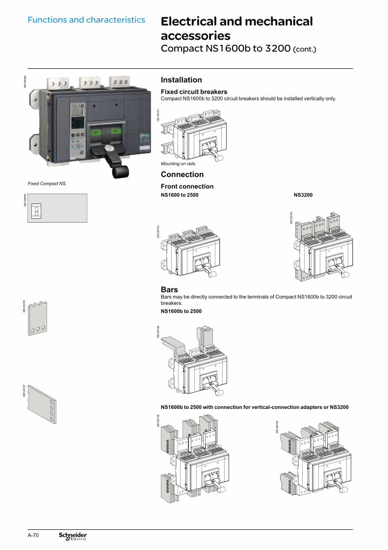
A-70
Electrical and mechanical accessoriesCompact NS1600b to 3200 (cont.)
Installation
Fixed circuit breakersCompact NS1600b to 3200 circuit breakers should be installed vertically only.
Connection
Front connection
NS1600 to 2500 NS3200
BarsBars may be directly connected to the terminals of Compact NS1600b to 3200 circuit breakers.NS1600b to 2500
NS1600b to 2500 with connection for vertical-connection adapters or NS3200
Functions and characteristicsP
B10
6366
Fixed Compact NS.
DB
1280
69D
B12
8155
DB
1281
57
DB
1281
53
FFO
FFO
DB
1281
54
FFO
FFO
DB
1281
56
OFF
OFF
DB
1281
58
O FF
FO F
DB
1281
59
OFF
OFF
DB
1281
51
FFO
O FF
Mounting on rails.

A-71
Indication contacts
Contacts installed in the deviceChangeover contacts are used to remote circuit breaker status information and can thus be used for indications, electrical locking, relaying, etc.They comply with the IEC 60947-5 international recommendation.Functions
OF (ON/OFF) - indicates the position of the main circuit breaker contacts bSD (trip indication) - indicates that the circuit breaker has tripped due to: ban overload va short-circuit van earth-leakage fault voperation of a voltage release voperation of the "push to trip" button vReturns to de-energised state when the circuit breaker is reset. b
SDE (fault indication) - indicates that the circuit breaker has tripped due to:an overload va short-circuit van earth-leakage fault. v
Returns to de-energised state when the circuit breaker is reset.Installation
OF, SD and SDE functions - a single type of contact provides all these different bindication functions, depending on the position where it is inserted in the device. The contacts clip into slots behind the front cover of the circuit breaker.Electrical characteristics of the OF/SD/SDE auxiliary contacts
All the auxiliary contacts opposite are also available in "low-level" versions capable of switching very low loads (e.g. for the control of PLCs or electronic circuits).
0545
49-1
8
OF, SD and SDE changeover contacts.
Contacts Standard Low levelRated thermal current (A) 6 5Minimum load 100 mA at 24 V 1 mA at 4 VUtilisation cat. (IEC 60947-5-1) AC12 AC15 DC12 DC14 AC12 AC15 DC12 DC14Operational 24 V 6 6 6 1 5 3 5 1current (A) 48 V 6 6 2.5 0.2 5 3 2.5 0.2
110 V 6 5 0.6 0.05 5 2.5 0.6 0.05220/240 V 6 4 - - 5 2 - -250 V - - 0.3 0.03 5 - 0.3 0.03380/440 V 6 2 - - 5 1.5 - -480 V 6 1.5 - - 5 1 - -660/690 V 6 0.1 - - - - - -

A-72
Electrical and mechanical accessoriesCompact NS1600b to 3200 (cont.)
Compact NS1600b to 3200 circuit breakers may be equipped with an MX shunt release, an MN undervoltage release or a delayed undervoltage release (MNR = MN + delay unit).
Remote trippingThis function opens the circuit breaker via an electrical order. It is made up of:
a shunt release 2 b nd MXor an undervoltage release MN bor a delayed undervoltage release MNR = MN + delay unit. b
These releases (2nd MX or MN) cannot be operated by the communication bus.The delay unit, installed outside the circuit breaker, may be disabled by an emergency OFF button to obtain instantaneous opening of the circuit breaker.Wiring diagram for the remote-tripping function
Voltage releases 2nd MXWhen energised, the 2nd MX voltage release instantaneously opens the circuit breaker. A continuous supply of power to the 2nd MX locks the circuit breaker in the OFF position.
Functions and characteristics
CharacteristicsPower supply V AC 50/60 Hz 24 - 48 - 100/130 - 200/250 - 277 - 380/480
V DC 12 - 24/30 - 48/60 - 100/130 - 200/250 Operating threshold 0.7 to 1.1 UnPermanent locking function 0.85 to 1.1 UnConsumption (VA or W) pick-up: 200 (80 ms) hold: 4.5Circuit breaker response 50 ms ±10time at Un
Instantaneous voltage releases MN
The MN release instantaneously opens the circuit breaker when its supply voltage drops to a value between 35 % and 70 % of its rated voltage. If there is no supply on the release, it is impossible to close the circuit breaker, either manually or electrically. Any attempt to close the circuit breaker has no effect on the main contacts. Circuit breaker closing is enabled again when the supply voltage of the release returns to 85 % of its rated value.
CharacteristicsPower supply V AC 50/60 Hz 24 - 48 - 100/130 - 200/250 - 380/480
V DC 24/30 - 48/60 - 100/130 - 200/250 Operating opening 0.35 to 0.7 Unthreshold closing 0.85 UnConsumption (VA or W) pick-up: 200 (200 ms) hold: 4.5MN consumption pick-up: 400 (200 ms) hold: 4.5with delay unit (VA or W)Circuit breaker response 90 ms ±5 time at Un
MN delay units
To eliminate circuit breaker nuisance tripping during short voltage dips, operation of the MN release can be delayed. This function is achieved by adding an external delay unit in the MN voltage-release circuit. Two versions are available, adjustable and non-adjustable.
CharacteristicsPower supply non-adjustable 100/130 - 200/250V AC 50-60 Hz /DC adjustable 48/60 - 100/130 - 200/250 - 380/480Operating threshold opening 0.35 to 0.7 Un
closing 0.85 UnConsumption of delay pick-up: 200 (200 ms) hold: 4.5unit alone (VA or W)Circuit breaker response non-adjustable 0.25 stime at Un adjustable 0.5 s - 0.9 s - 1.5 s - 3 s
DB
1281
38
Openingorder
D2
D1
MN
DB
1281
37
C2
C1
MX
Openingorder
DB
1281
39
MN
D2
D1
10 12
3 6
Delayedopeningorder
Instantaneousopeningorder
Delayunit
0564
21
MX voltage release

A-73
Device lockingLocking in the OFF position guarantees isolation as per IEC 60947-2.Padlocking systems can receive up to three padlocks with shackle diameters ranging from 5 to 8 mm (padlocks not supplied).
Control device Function Means Required
accessoriesToggle lock in OFF position padlock removable device
lock in OFF or ON padlock fixed deviceposition
Interphase barriersThese barriers are flexible insulated partitions used to reinforce isolation of connection points in installations with busbars, whether insulated or not.Barriers are installed vertically between front connection terminals.
Escutcheon CDPOptional equipment mounted on the door of the cubicle, the escutcheon increases the degree of protection to IP40.
PB
1048
36_M
E
Compact NS with toggle locked using a fixed device and padlocks.
PB
1048
35_M
E
Compact NS with toggle locked using a removable device and padlocks.
DB
1281
28
Interphase barriers.
DB
1281
61
Escutcheon.

B-1
Compact NS630b to 3200 Installation recommendationsContents
Presentation 2Functions and characteristics A-1
Operating conditions B-2
Installation in switchboards B-3Power supply and weights B-3Safety clearances and minimum distances B-4Installation example B-5
Door interlock for Compact NS630b to 1600 B-6
Control wiring B-7
Temperature derating B-8Compact NS devices equipped with electronic trip units B-8
Power dissipation / Resistance B-9Compact NS devices equipped with electronic trip units B-9
Dimensions and connection C-1Electrical diagrams D-1Additional characteristics E-1

B-2
Altitude deratingAltitude does not significantly affect circuit-breaker characteristics up to 2000 m. Above this altitude, it is necessary to take into account the decrease in the dielectric strength and cooling capacity of air.The following table gives the corrections to be applied for altitudes above 2000 metres. The breaking capacities remain unchanged.
Compact NS630b to 3200
Altitude (m) 2000 3000 4000 5000Impulse withstand voltage Uimp (kV) 8 7.1 6.4 5.6Rated insulation voltage (Ui) 800 710 635 560Maximum rated operationnal voltage 50/60 Hz Ue (V) 690 690 635 560Rated current 40 °C 1 x In 0.99 x In 0.96 x In 0.94 x InIntermediate values may be obtained by interpolation.
VibrationsCompact NS devices resist electromagnetic or mechanical vibrations.Tests are carried out in compliance with standard IEC 60068-2-6 for the levels required by merchant-marine inspection organisations (Veritas, Lloyd’s, etc.):
2 b V 13.2 Hz: amplitude ±1 mm13.2 b V 100 Hz: constant acceleration 0.7 g.
Excessive vibration may cause tripping, breaks in connections or damage to mechanical parts.
Electromagnetic disturbancesCompact NS devices are protected against:
overvoltages caused by devices that generate electromagnetic disturbances bovervoltages caused by an atmospheric disturbances or by a distribution-system b
outage (e.g. failure of a lighting system)devices emitting radio waves (radios, walkie-talkies, radar, etc.) belectrostatic discharges produced by users. b
Compact NS devices have successfully passed the electromagnetic-compatibility tests (EMC) defined by the following international standards:
IEC 60947-2, appendix F bIEC 60947-2, appendix B (trip units with Vigi earth-leakage function). b
The above tests guarantee that:no nuisance tripping occurs btripping times are respected. b
Operating conditionsInstallationrecommendations
DB
1281
62
2000(m)
DB
1281
63D
B12
8164
Compact circuit breakers have been tested for operation in industrial atmospheres. It is recommended that the equipment be cooled or heated to the proper operating temperature and kept free of excessive vibration and dust.
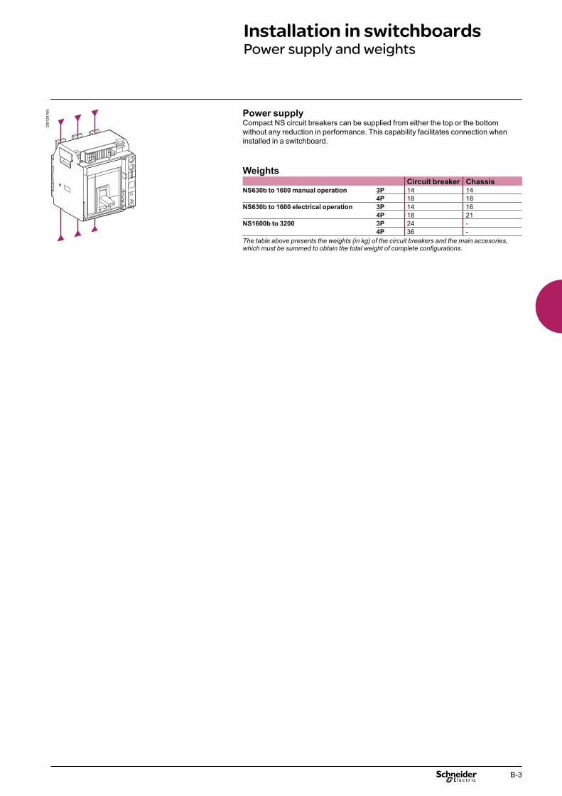
B-3
Installation in switchboardsPower supply and weights
DB
1281
65 Power supplyCompact NS circuit breakers can be supplied from either the top or the bottom without any reduction in performance. This capability facilitates connection when installed in a switchboard.
WeightsCircuit breaker Chassis
NS630b to 1600 manual operation 3P 14 144P 18 18
NS630b to 1600 electrical operation 3P 14 164P 18 21
NS1600b to 3200 3P 24 -4P 36 -
The table above presents the weights (in kg) of the circuit breakers and the main accesories, which must be summed to obtain the total weight of complete configurations.

B-4
Installation in switchboardsSafety clearances and minimum distances
General rulesWhen installing a circuit breaker, minimum distances (safety clearances) must be maintained between the device and panels, bars and other protection devices installed nearby. These distances, which depend on the ultimate breaking capacity, are defined by tests carried out in accordance with standard IEC 60947-2.If installation conformity is not checked by type tests, it is also necessary to:
use insulated bars for circuit-breaker connections bblock off the busbars using insulating screens. b
Installationrecommendations
Compact NS630b to 3200 (fixed devices)
Insulated parts Metal parts Live partsNS630b to 1600
A 0 120 180B 0 10 60NS1600b to 3200
A 50 170 230B 0 10 60
Compact NS630b to 1600 (withdrawable devices)
Insulated parts Metal parts Live partsA 0 0 30B 10 10 60C 0 0 30 F Datum
DB
1281
66
F146.5
A (*)
DB
1281
67 A (*) BB
(*) An overhead clearance of 50 mm is required to remove the arc chutes.
DB
1281
68
F
40180
A
DB
1281
69 B BC C
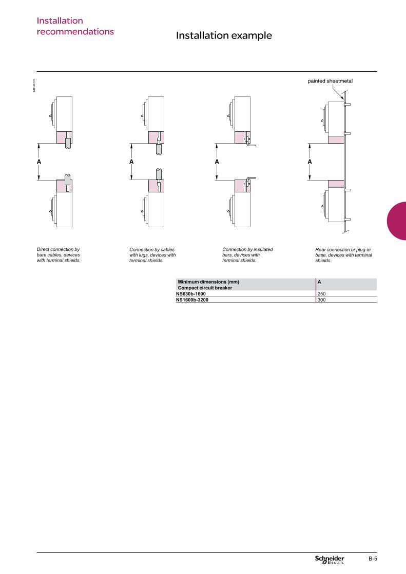
B-5
DB
1281
70
Minimum dimensions (mm) A
Compact circuit breaker
NS630b-1600 250NS1600b-3200 300
Connection by cables with lugs, devices with terminal shields.
Connection by insulated bars, devices with terminal shields.
Rear connection or plug-in base, devices with terminal shields.
Direct connection by bare cables, devices with terminal shields.
Installation exampleInstallationrecommendations

B-6
Door interlock for Compact NS630b to 1600
Note. The door interlock may be mounted on either the left or right-hand side of the chassis. F Datum
Device in the connected or test positions
Door locked
Device in the disconnected position
Door not locked
Dimensions (mm)Type (1) (2)
NS630b to 1600 (3P) 135 168NS630b to 1600 (4P) 205 168
Mounted on the left or right-hand side of the chassis, this locking device prevents opening of the door if the circuit breaker is in the connected or test positions. If the circuit breaker was connected with the door open, the door may be closed without having to disconnect the circuit breaker.
DB
1280
26
61
11
2
4
(2) (1)
Y
X
DB
1280
28
5
F
23
Door
DB
1281
71
Installationrecommendations

B-7
Control wiring
Wiring of voltage releasesDuring pick-up, the power consumed is approximately 150 to 200 VA. For low control voltages (12, 24, 48 V), maximum cable lengths are imposed by the voltage and the cross-sectional area of cables.
Recommended maximum cable lengths (meter).12 V 24 V 48 V
2.5 mm2 1.5 mm2 2.5 mm2 1.5 mm2 2.5 mm2 1.5 mm2
MN U source 100 % – – 58 35 280 165U source 85 % – – 16 10 75 45
MX-XF U source 100 % 21 12 115 70 550 330U source 85 % 10 6 75 44 350 210
Note: the indicated length is that of each of the two wires.
24 V DC power-supply module
External 24 V DC power-supply module for Micrologic (F1-, F2+)
do not connect the positive terminal (F2+) to earth bthe negative terminal (F1-) can be connected to earth, except in IT systems ba number of Micrologic control units and M6C modules can be connected to the b
same 24 V DC power supply (the consumption of a Micrologic control unit or an M6C module is approximately 100 mA)
do not connect any devices other than a Micrologic control unit or an M6C bmodule if voltage > 480 V AC or in an environment with high level of electromagnetic desturbance
the maximum length for each conductor is ten metres. For greater distances, bit is advised to twist the supply wires together
the 24 V DC supply wires must cross the power cables perpendicularly. bIf this is difficult, it is advised to twist the supply wires together
the technical characteristics of the external 24 V DC power-supply module bfor Micrologic control units are indicated on page A-28.Communication bus
do not connect the positive terminal (E1) to earth bthe negative terminal (E2) can be connected to earth ba number of "device" or "chassis" communication modules can be connected b
to the same 24 V DC power supply (the consumption of each module is approximately 30 mA).
Note: wiring of ZSI: it is recommended to use twisted shielded cable. The shield must be connected to earth at both ends.
Installationrecommendations

B-8
Compact NS630b to NS1600 (1)
The table below indicates the maximum rated-current value for each type of connection, depending on the ambient temperature.For mixed connections, use the same derating values as for horizontal connections.
Version Fixed device
Connection Front or horizontal rear Vertical rear
temp. Ti (2) 40 45 50 55 60 65 70 40 45 50 55 60 65 70NS630b N/L 630 630 630 630 630 630 630 630 630 630 630 630 630 630NS800 N/L 800 800 800 800 800 800 800 800 800 800 800 800 800 800NS1000 N/L 1000 1000 1000 1000 1000 1000 1000 1000 1000 1000 1000 1000 1000 1000NS1250 N 1250 1250 1250 1250 1250 1240 1090 1250 1250 1250 1250 1250 1250 1180NS1600 N 1600 1600 1560 1510 1470 1420 1360 1600 1600 1600 1600 1600 1510 1460
Version Withdrawable device
Connection Front or horizontal rear Vertical rear
temp. Ti (2) 40 45 50 55 60 65 70 40 45 50 55 60 65 70NS630b N/L 630 630 630 630 630 630 630 630 630 630 630 630 630 630NS800 N/L 800 800 800 800 800 800 800 800 800 800 800 800 800 800NS1000 N/L 1000 1000 1000 1000 1000 1000 920 1000 1000 1000 1000 1000 1000 990NS1250 N 1250 1250 1250 1250 1250 1170 1000 1250 1250 1250 1250 1250 1250 1090NS1600 N 1600 1600 1520 1480 1430 1330 1160 1600 1600 1600 1560 1510 1420 1250
Compact NS1600b to 3200
Version Fixed device
Connection Front or horizontal rear Vertical rear
temp. Ti (2) 40 45 50 55 60 65 70 40 45 50 55 60 65 70NS1600b N 1600 1600 1600 1600 1500 1450 1400 1600 1600 1600 1600 1600 1550 1500NS2000 N 2000 2000 2000 2000 1900 1800 1700 2000 2000 2000 2000 2000 1900 1800NS2500 N 2500 2500 2500 2500 2500 2500 2500 2500 2500 2500 2500 2500 2500 2500NS3200 N - - - - - - - 3200 3200 3200 3180 3080 2970 2860(1) For a circuit breaker mounted in horizontal position, the derating to be applied is equivalent to that of a front or horizontal rear connected circuit breaker.(2) Ti: temperature around the circuit breaker and its connections.
Temperature deratingCompact NS devices equipped with electronic trip units
Installationrecommendations
Compact circuit breakers have been tested for operation in industrial atmospheres. It is recommended that the equipment be cooled or heated to the proper operating temperature and kept free of excessive vibration and dust.

B-9
Compact NS630b to 1600Version Fixed device
N L LB
R/pole P/pole R/pole P/pole R/pole P/pole
NS630b 0.026 10 0.039 15 0.056 15NS800 0.026 15 0.039 20 0.056 20NS1000 0.026 22 0.039 34NS1250 0.026 44NS1600 0.026 74
Version Withdrawable device
N L LB
R/pole P/pole R/pole P/pole R/pole P/pole
NS630b 0.038 19 0.072 34 0.086 34NS800 0.038 30 0.072 40 0.086 40NS1000 0.038 50 0.072 77NS1250 0.036 84NS1600 0.036 154
Compact NS1600b to 3200Version Fixed device
N
R/pole P/pole
NS1600b 0.019 84NS2000 0.013 84NS2500 0.008 100NS3200 0.008 227
Power dissipation / ResistanceCompact NS devices equipped with electronic trip units
The values indicated in the tables opposite are typical values.Power dissipated per pole (P/pole) in Watts (W)
The value indicated in the table is the power dissipated at IN, 50/60 Hz, for a three-pole or four-pole circuit breaker (these values can be higher than the power calculated on the basis of the pole resistance). Measurement and calculation of the dissipated power are carried out in compliance with the recommendations of Annex G of standard IEC 60947-2.Resistance per pole (R/pole) in milliohms (mΩ)
The value of the resistance per pole is provided as a general indication for a new device.The value of the contact resistance must be determined on the basis of the measured voltage drop, in accordance with the manufacturer’s test procedure (expert card ABT no. FE 05e).
Note: this measurement is not sufficient to determine the quality of the contacts, i.e. the capacity of the circuit breaker to carry its rated current.
Installationrecommendations

B-10
C-1
Compact NS630b to 3200 Dimensions and connectionContents
Presentation 2Functions and characteristics A-1Installation recommendations B-1
Compact NS630b to 1600 (fixed version) C-2Dimensions C-2Mounting C-3Front-panel cutouts C-4Rotary handle C-5
Compact NS630b to 1600 (withdrawable version) C-6Dimensions, mounting and cutouts C-6Rotary handle C-7
Compact NS1600b to 3200 (fixed version) C-8Dimensions C-8
Compact NS630b to 3200 C-9External modules C-9
Accessories NS630b to 3200 C-13
Compact NS630b to 1600 (fixed version) C-14Bars C-14Cables with lugs and bare cables C-17
Compact NS630b to 1600
(plug-in and withdrawable versions) C-18Bars C-18Cables with lugs C-20
Compact NS1600b to 3200 (fixed version) C-21Recommended drilling dimensions C-22
Power connections for Compact NS1600b to 3200 C-23Recommended drilling dimensions C-23Sizing of bars C-26
Electrical diagrams D-1Additional characteristics E-1
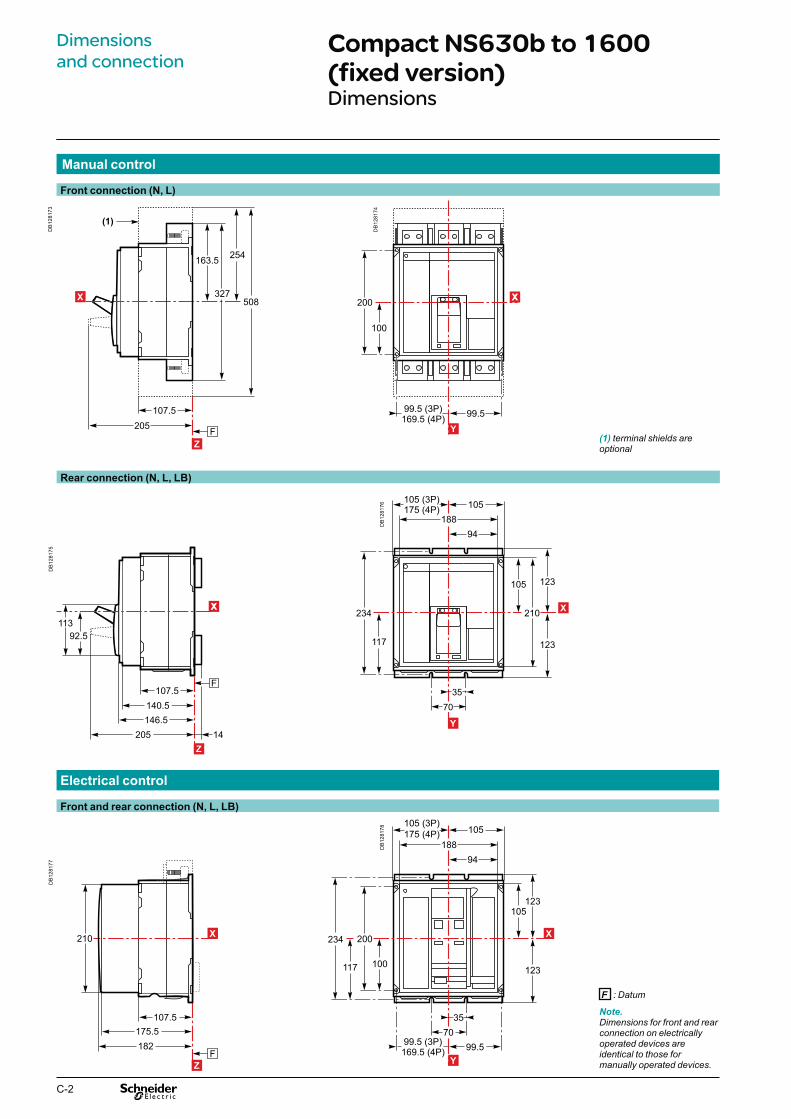
C-2
105
94
105105 (3P)175 (4P)
188
123
99.599.5 (3P)169.5 (4P)
3570
117
234
100
200
123
Y
X
210
105
94
105105 (3P)175 (4P)
188
123
3570
117
234
123
Y
X
99.5
200
99.5 (3P)169.5 (4P)
100
Y
XX
Compact NS630b to 1600 (fixed version)Dimensions
Electrical control
Front and rear connection (N, L, LB)
DB
1281
78
Rear connection (N, L, LB)
DB
1281
76
Manual control
Front connection (N, L)
DB
1281
74
Note.Dimensions for front and rear connection on electrically operated devices are identical to those for manually operated devices.
F : Datum
(1) terminal shields are optional
DB
1281
73
F
254
508
107.5205
163.5
327
(1)
Z
X
DB
1281
75
F
205 14
92.5113
107.5140.5146.5
Z
XX
DB
1281
77
F
210
182175.5
107.5
Z
X
Dimensions and connection

C-3
Front connection
On backplate On rails
Rear connection
On backplate or rails
3P 4P
Note.Mounting parameters for electrically operated devices are identical to those for manually operated devices.X and Y are the symmetry planes for a 3-pole deviceZ is the back plane of the device.
Mounting
DB
1281
79
Y
X
99.5 (3P)169.5 (4P) 99.5
100
4 Ø6.5
200
DB
1281
80 Y
X
99.5 (3P)169.5 (4P) 99.5
100
4 Ø6.5
200
DB
1281
81
Y
X
DB
1281
82 Y
X

C-4
Electrical control
Door cutout
A
Toggle control
Door cutout
A B
(1) Without escutcheon.(2) With escutcheon.
(1) Without escutcheon.(2) With escutcheon.
Compact NS630b to 1600 (fixed version)Front-panel cutouts
F : Datum.
F : Datum.
DB
1281
83
(C)(B)(A)
150(2)
F
124 mini(1) (2)
107.5140.5146.5
Z
X
DB
1281
84
216 (1)266 (2)
194 mini (3P)264 mini (4P) 194 mini
108 (1)133 (2)
97 (1)122 (2)
194 (1)244 (2)
Y
X
DB
1281
85
194 mini (3P)264 mini (4P) 194 mini
100.5 (1)
201(1)
90.5 (1)
181 (1)
Y
X
DB
1281
86
119 (1)144 (2)
194 mini (3P)264 mini (4P) 194 mini
95.5 (1)108 (2)
35.5 (1)60.5 (2)71 (1)
121 (2)
Y
XX
DB
1281
87
(A)
F
150 mini(1) (2)
107.5175.5182
Z
X
DB
1281
84
216 (1)266 (2)
194 mini (3P)264 mini (4P) 194 mini
108 (1)133 (2)
97 (1)122 (2)
194 (1)244 (2)
Y
X
Dimensions and connection

C-5
Extended rotary handle
Dimensions Door cutout
Rotary handle
Direct rotary handle
Dimensions
Door cutout
A B D
F : Datum
DB
1281
89
(D)(B)(A)
F229.5
195
180 mini(2)
124 mini(1) (2)
107.5140.5146.6
175.5
Z
XD
B12
8190
R80
60°
60°
25
24
Y
X
DB
1281
84
216 (1)266 (2)
194 mini (3P)264 mini (4P) 194 mini
108 (1)133 (2)
97 (1)122 (2)
194 (1)244 (2)
Y
X
(1) Without escutcheon.(2) With escutcheon.
DB
1281
92
201 (1)
194 mini
90.5 (1)
181 (1)
100.5 (1)
X
YD
B12
8193
201 (1)
194 mini (3P)264 mini (4P) 194 mini
90.5 (1)
130 (1)
100.5 (1)
Y
X
DB
1281
94
F231.5 mini605.5 maxi
212.5
Z
X
DB
1281
95
R100
60°
60°
25
24
Y
X
Note.X and Y are the symmetry planes for a 3-pole deviceZ is the back plane of the device.
DB
1281
96 Y
X

C-6
Compact NS630b to 1600 (withdrawable version)Dimensions, mounting and cutouts
Dimensions
Manual control Electrical control
Mounting
Bottom mounting on base plate or rails Vertical on uprights or backplate
Cutouts
Door cutout Rear panel cutout
F : Datum
DB
1281
97 210mini
70 (*)
60 mini
569
F
X
DB
1281
98 210mini
46 (*)
60 mini
545.5
F
X
(*) Withdrawable position
DB
1281
99
90
94188
160.5127.5 (3P)197.5 (4P)
123
199
90 (3P)160 (4P)
Y
X
DB
1282
00
F
25100
24
231216
X DB
1282
01
Y
F
DB
1282
02 Y
X
DB
1282
03
259 (1)303 (2)
170 mini (3P)240 mini (4P) 230 mini
109 (1)130.8 (2)
161 (1)183 (2) 259 (1)
307 (2)
Y
X
(1) Without escutcheon.(2) With escutcheon.
DB
1282
04
117
234
102.5102.5 (3P)172.5 (4P)
Y
X
Note.X and Y are the symmetry planes for a 3-pole device.
Dimensions and connection

C-7
(1) Without escutcheon.(2) With escutcheon.
Door cutout
(*) Withdrawable position.
Rotary handle
Direct rotary handle
Dimensions
Extended rotary handle
Dimensions Door cutout
DB
1282
05
136 (*)
210mini
93
60 mini
5
F
X
DB
1282
06
R80
25
60°
2460°
Y
X
DB
1282
07
161 (1)183 (2)259 (1)
307 (2)
259 (1)303 (2)
170 mini (3P)240 mini (4P) 230 mini
109 (1)130.8 (2)
Y
X
DB
1282
08
207 mini447 maxi
F
17
X
DB
1282
09
A66974E
R200
60°
60°
25
24
Y
X
Note.X and Y are the symmetry planes for a 3-pole device.
DB
1282
10 Y
X

C-8
Compact NS1600b to 3200 (fixed version)Dimensions
Dimensions
Y
X
4 Ø12
75
150
195195 (3P)310 (4P)
DB
1282
16
Note.X and Y are the symmetry planes for a 3-pole device
C Mounting on rails
DB
1282
11
165
330
132
368
162.5168.5
F
18.5
222.5
(C)
(B)(A) 132 mini
38.5
Z
X
DB
1282
12 Y
X
Door cutout (A, B, C)
A B
DB
1282
13
346 (1)397 (2)
216 (1)267 (2)
108 (1)133.5 (2)
173 (1)198.5 (2)
Y
X
DB
1282
14
332
201
100.5
166
Y
X
DB
1282
15
119
146
73
95.9
Y
X
F : datum
(1) Without escutcheon.(2) With escutcheon.
Dimensions and connection
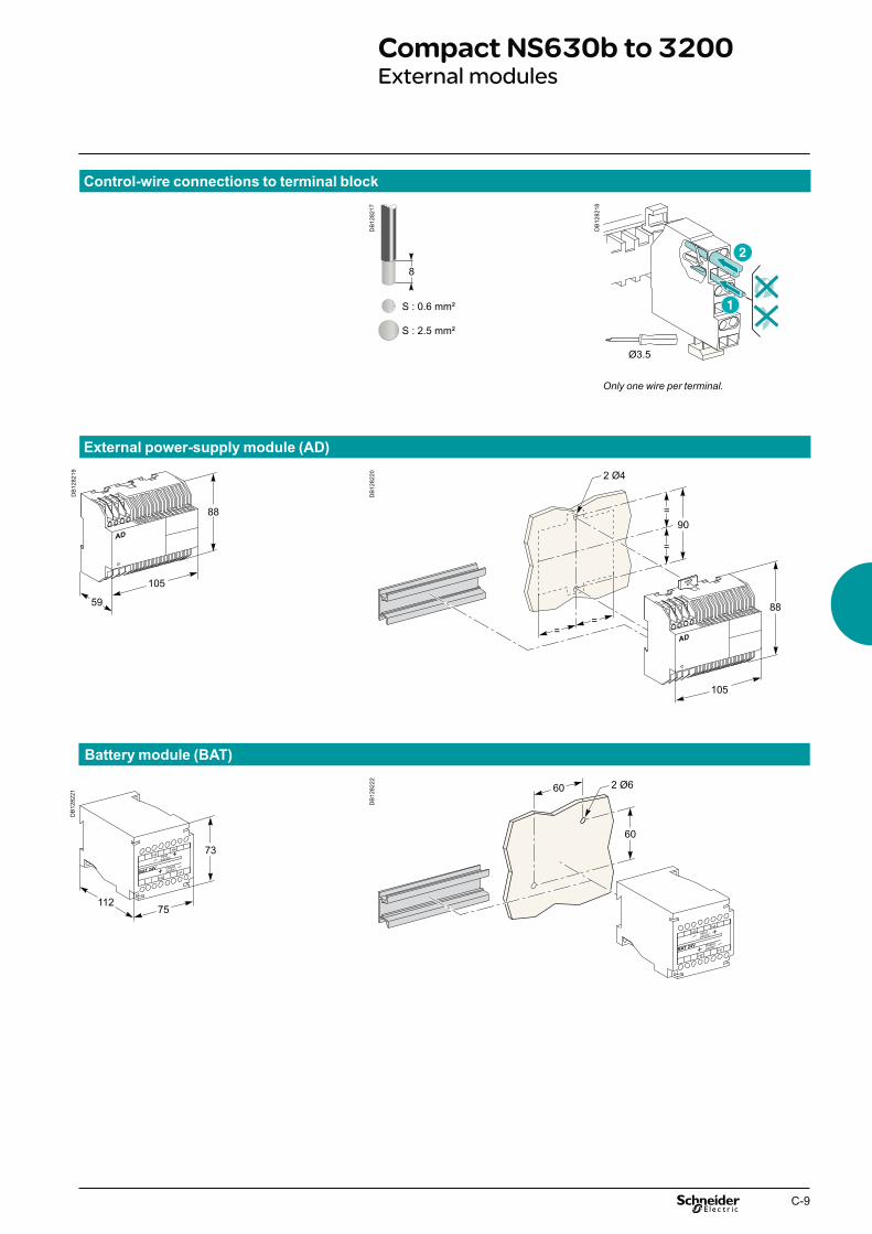
C-9
Compact NS630b to 3200External modules
External power-supply module (AD)
Battery module (BAT)
Control-wire connections to terminal block
DB
1282
17
8
S : 0.6 mm²
S : 2.5 mm²
DB
1282
18
Ø3.5
Only one wire per terminal.
DB
1282
19
88
59
105
DB
1282
20
88
90
2 Ø4
105
DB
1282
21
H3
H2BAT 24V
H4
H1
Input24VDC
+ Output
24VDC
+ 73
75112
DB
1282
22
60
60
2 Ø6

C-10
MN delay unit
Chassis communication module
Modbus
External sensor for source ground return (SGR) protection
External sensor "MDGF" summing module
DB
1282
23
3 6
MNUVR
1012
100/130 V
AC/DC
S
0.5 1
3 1.5
Retardateur de MN
Time delay for UVR
654321
321
7273.5
81 42
DB
1282
24
46
73
66
2 Ø4.257
DB
1282
25
+
+
CCM modbus
uaeséR
krowte
N
Fault
Com.
Address
sync.
dleihs’B’A B A
’B’A B A
ruet cno jsiD
rekaerB
+
ECD
CTC
45
5458
90
DB
1282
26
45
200
15076
130
DB
1282
27
MDGF
45
10658
90
Compact NS630b to 3200External modules
Dimensions and connection

C-11
Compact NS630b to 3200External modules (cont.)
External sensor for neutral
400/1600 A (NS630b to 1600)
1000/4000 A (NS1600b to 3200)
Installation
400/1600 (NS630b to NS1600) 1000/4000 A (NS1600b to NS3200)
DB
1282
28
177208
35 76
4 Ø14
DB
1282
29 8 Ø14
12744
44 44174
295
DB
1282
30
DB
1282
31

C-12
Busbars path
280 x 115 mm window
Busbars spaced 70 mm centre-to-centre
470 x 160 mm window
Busbars spaced 115 mm centre-to-centre
280 x 115 mm window
Rectangular sensor for earth leakage protection (Vigi)
470 x 160 mm window
Busbars I y 1600 A I y 3200 AWindow (mm) 280 x 115 470 x 160Weight (kg) 14 18
DB
1282
32 DB
1282
33 4 Ø9
280362
233216
197115
381
71D
B12
8235 8 Ø9
572
281
72470456
146160
242263
552
DB
1282
36
2 bars 50 x 10
DB
1282
37 M1 M2 M3
4 bars 100 x 5
DB
1282
38
2 bars 100 x 5
DB
1282
39 M1 M2 M3
4 bars 125 x 5
DB
1282
34Compact NS630b to 3200External modules (cont.)
Dimensions and connection

C-13
Escutcheon
NS630b to NS1600 (fixed control)A C
Accessories NS630b to 3200
NS630b to NS1600 (withdrawable control)
NS1600b to NS3200 (fixed control)
DB
1282
40
(C)
(A)
X
DB
1282
41
275
27
27253
Y
X
DB
1282
42
27
154
27131
Y
X
DB
1282
43
X
DB
1282
44
313
27
2727317
13
Y
X
DB
1282
46
27
202.5
275
137.5
27405
Y
X
DB
1282
45
X
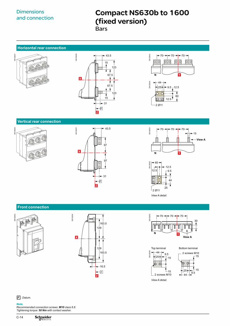
C-14
Compact NS630b to 1600 (fixed version)Bars
Note.Recommended connection screws: M10 class 8.8.Tightening torque: 50 Nm with contact washer.
F : Datum.
Dimensionsand connection
Horizontal rear connection
Vertical rear connection
Front connection
DB
1282
47
DB
1282
48
E47
904A
15
15
67.5
67.5
123
123
43.5
31
Z
X
F
DB
1280
41
N
707070
Y
DB
1282
49 44
25 9.5 12.5
12.5
2 Ø11
60
DB
1282
50
DB
1282
51
F
43.5
31
97
97
Z
XD
B12
8051
N
70707015
View A
YD
B12
8252
44
25
9.512.5
12.5
2 Ø11
60
View A detail.
DB
1282
53
DB
1282
54
129
129163.5
F
163.5
16.5
Z
X
DB
1282
55
N
707070
View A
30
Y
Top terminal Bottom terminal
DB
1282
56
259.5
44
152 screws M10
15
9.52544
152 screws M10
15
View A detail.

C-15
Note.X and Y are the symmetry planes for a 3-pole device.
Middle left or middle right spreader for 4P
Middle spreader for 3P Left or right spreader for 4P Left or right spreader for 3PSpreader detail
Front connection with spreaders
Rear connection with spreaders
DB
1282
65
View A detail.
DB
1282
59 7070
25
15
25
View AY
DB
1282
60
N
70 70 70
12.5 12.5
95 95 95
15View A
Y
DB
1282
58
181
181
F
31.5
196
196
Z
X
DB
1282
57D
B12
8261
DB
1282
62
15
52.5
82.5
123
123
98
15
83
FZ
X
DB
1282
63
70 7095 95
Y
DB
1282
64
N
7070 70
12.5 12.5
95 95 95
Y
DB
1282
66
DB
1282
67
DB
1282
68
F : Datum.

C-16
Note.(1) two mounting possibilities for vertical-connection adapters (pitch 21 mm).Recommended connection screws: M10 class 8.8.Tightening torque: 50 Nm with contact washer.
Compact NS630b to 1600 (fixed version)Bars
Dimensionsand connection
Front connection with vertical-connection adapters
DB
1282
69
DB
1282
70200
200
430
1062.5
Z
X
F
DB
1281
52
N
15707070
View A
Y
DB
1282
71
View A detail.
F : Datum.

C-17
Front connection with vertical-connection adapters and cable-lug adapters
Cables with lugs and bare cables
Front connection with vertical-connection adapters and cable-lug adapters
Lugs
Fixed circuit breaker with 4-cable bare-cable connectors (240 mm2)
DB
1282
75
View A detail.
DB
1282
72
DB
1282
73
200
200
250
10
150
250
15
15
530
Z
X
FD
B12
8274
15N
707070
View A
Y
DB
1282
76
DB
1282
77 Ø20.5 : 240 mm²Ø23 : 300 mm²
25
DB
1282
78
Ø10
31
89.5
11.5
DB
1282
82
DB
1282
79
DB
1282
80
F
398
16.5
199
199
3561
206.5
206.5
413
Z
X
DB
1282
81
N
707070
Y
F : Datum.

C-18
Compact NS630b to 1600 (plug-in and withdrawable versions)Bars
Note.Recommended connection screws: M10 class 8.8.Tightening torque: 50 Nm with contact washer.
Dimensionsand connection
Horizontal rear connection
Vertical rear connection
Front connection
DB
1282
83
DB
1282
84
267.5F
15
67.5
114
49
15
67.5228X
DB
1282
85
N
707070
Y
DB
1282
49 44
25 9.5 12.5
12.5
2 Ø11
60
DB
1282
87
DB
1282
88
267.5F
97
49
97
XD
B12
8289
N
7015
70 70
View A
Y
DB
1282
52
44
25
9.512.5
12.5
2 Ø11
60
View A detail.
DB
1282
91
DB
1282
92
235
171
12.5
12.5
336
140
15
X
F
DB
1282
94
View A detail.
DB
1282
93
N
70 70 70 View A
Y
Top terminal Bottom terminal
F : Datum.

C-19
Front connection with spreaders
Middle left or middle right spreader for 4P
Middle spreader for 3P Left or right spreader for 4P Left or right spreader for 3PSpreader detail
Front connection with spreaders
DB
1282
65
View A detail.
DB
1282
95
DB
1282
96
250
223
207192
238
X
F
DB
1282
97
707095 95
View A
Y
DB
1282
98
N
70707095 95 95
12.512.5View A
Y
DB
1282
66
DB
1282
67
DB
1282
68
F : Datum.

C-20
Compact NS630b to 1600 (plug-in and withdrawable versions) Cables with lugs
Note.X and Y are the symmetry planes for a 3-pole device.Recommended connection screws: M10 class 8.8.Tightening torque: 50 Nm with contact washer.
Front connection with vertical-connection adapters and cable-lug adapters
Dimensionsand connection
Front connection with vertical-connection adapters and cable-lug adaptersFront connection with vertical-connection adapters and cable-lug adapters
Lugs
DB
1282
75
View A detail.
DB
1283
03
DB
1283
04
193.5
50
292
583
15
15
71
171
140
71
50
261
21
21
X
F
DB
1283
05
N
7015
15
70 70View A
Y
DB
1282
76
DB
1282
77 Ø20.5 : 240 mm²Ø23 : 300 mm²
25
DB
1282
78
Ø10
31
89.5
11.5
F : Datum.

C-21
Compact NS1600b to 3200 (fixed version)
Note.Recommended connection screws: M10 class 8.8.Tightening torque: 50 Nm with contact washer.
Front connection (NS1600b to 2500)
Front connection with vertical-connection adapters (NS1600b to 2500)
Front connection (NS3200)
DB
1283
13
View A detail.
DB
1283
10
OFF
OFF
DB
1283
11
150165
20
165150
Z
X
F
DB
1283
12 115 115 115
NView A
Y
DB
1283
17
View A detail.
DB
1283
14
OFF
OFF
DB
1283
15
25
230
230
142.5
142.5
40
Z
X
F
DB
1283
16
Z
e
max.123min. 8103.5 45 36
X
DB
1283
17
View A detail.
DB
1283
18
OFF
OFF
DB
1283
19
4025
230
230
142.5
142.5
Z
X
F
DB
1283
20
N
115 115 115
View AY

C-22
Rear connection Rear connection with spreaders
Middle left or middle
right spreader for 4P
Middle spreader for 3P Left or right spreader for
4P
Left or right spreader
for 3P
Vertical rear connection
Front connection Front connection with vertical-connection adapter
Top terminal Bottom terminal
Power connections for Compact NS630b to 1600Recommended drilling dimensions
DB
1283
22
DB
1283
24
DB
1283
22
DB
1283
25
DB
1283
26 44
25 9.5 12.5
12.5
2 Ø11
60
DB
1283
27
DB
1283
28
DB
1283
29
DB
1283
30
DB
1283
31
DB
1283
22
DB
1283
33
DB
1283
34
DB
1283
35
DB
1283
36
44
25
9.512.5
12.5
2 Ø11
60
DB
1283
22
DB
1283
24
DB
1283
22
DB
1283
25
DB
1283
41
259.5
44
152 M10 screws
15
9.52544
152 M10 screws
15
DB
1283
42
Dimensionsand connection
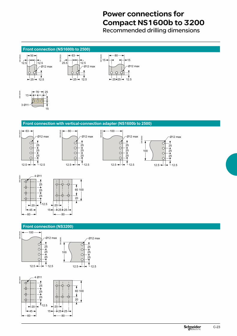
C-23
Front connection (NS1600b to 2500)
Power connections for Compact NS1600b to 3200Recommended drilling dimensions
Front connection with vertical-connection adapter (NS1600b to 2500)
Front connection (NS3200)
DB
1283
22
DB
1283
24
DB
1283
25
DB
1283
46D
B12
8347
DB
1283
48
DB
1283
49
DB
1283
50
DB
1283
49
DB
1283
50
DB
1283
51D
B12
8351
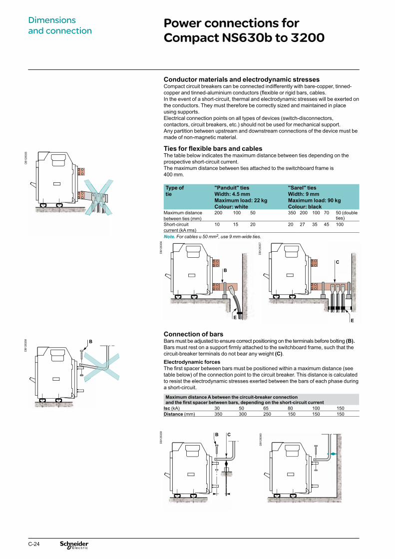
C-24
Power connections for Compact NS630b to 3200
Conductor materials and electrodynamic stressesCompact circuit breakers can be connected indifferently with bare-copper, tinned-copper and tinned-aluminium conductors (flexible or rigid bars, cables.In the event of a short-circuit, thermal and electrodynamic stresses will be exerted on the conductors. They must therefore be correctly sized and maintained in place using supports.Electrical connection points on all types of devices (switch-disconnectors, contactors, circuit breakers, etc.) should not be used for mechanical support.Any partition between upstream and downstream connections of the device must be made of non-magnetic material.
Ties for flexible bars and cablesThe table below indicates the maximum distance between ties depending on the prospective short-circuit current.The maximum distance between ties attached to the switchboard frame is 400 mm.
Type of "Panduit" ties "Sarel" ties
tie Width: 4.5 mm Width: 9 mm
Maximum load: 22 kg Maximum load: 90 kg
Colour: white Colour: blackMaximum distance 200 100 50 350 200 100 70 50 (double
ties)between ties (mm)Short-circuit 10 15 20 20 27 35 45 100current (kA rms)Note. For cables u 50 mm2, use 9 mm-wide ties.
Connection of barsBars must be adjusted to ensure correct positioning on the terminals before bolting (B).
Bars must rest on a support firmly attached to the switchboard frame, such that the circuit-breaker terminals do not bear any weight (C).Electrodynamic forces
The first spacer between bars must be positioned within a maximum distance (see table below) of the connection point to the circuit breaker. This distance is calculated to resist the electrodynamic stresses exerted between the bars of each phase during a short-circuit.
Maximum distance A between the circuit-breaker connection and the first spacer between bars, depending on the short-circuit current
Isc (kA) 30 50 65 80 100 150Distance (mm) 350 300 250 150 150 150
DB
1283
55D
B12
8358 B
DB
1283
56
B
E
DB
1283
57.
C
E
DB
1283
59 B C
DB
1283
60
Dimensionsand connection

C-25
ConnectionsThe quality of bar connections depends, among other things, on the tightening torques used for the nuts and bolts. Over-tightening may have the same consequences as under-tightening.The correct tightening torques for the connection of bars to the circuit-breaker terminals are indicated in the table below.The values below are for copper bars (Cu ETP-NFA51-100) and steel nuts and bolts (class 8.8). The same values apply to AGS-T52 quality aluminium bars (French standard NFA 02-104 and American National Standard H-35-1).Examples of bar connections
Tightening torque for bars
Rated diameter (mm) Drilling (mm) Tightening torque (Nm) Tightening torque (Nm)
diameter with flat or grower with contact or split
washers washers
10 11 37.5 50
Bar drilling
Examples
Insulation distance
Bar bendingBars must be bent according to the table below. A tighter bend may cause cracks.
Dimensions (mm)e Radius r
Minimum Recommended
5 5 7.510 15 18 to 20
terminal screws, factory tightened to 13 Nm1 circuit-breaker terminal2 bars3 bolt4 washer5 nut6
Dimensions (mm)Utilisation voltage X minimum
Ui y 600 V 8 mm
Ui y 1000 V 14 mm
DB
1283
61 4 532
6
1
DB
1283
62
DB
1283
63
DB
1283
64
DB
1283
65
DB
1283
67
DB
1283
66
DB
1283
68
X
DB
1283
69
e
r

C-26
Power connections for Compact NS630b to 3200Sizing of bars
Compact Maximum Ti: 40 °C Ti: 50 °C Ti: 60 °C
service Number of bars Number of bars Number of bars
current 5 mm thick 10 mm thick 5 mm thick 10 mm thick 5 mm thick 10 mm thickNS630b 400 2b.30 x 5 1b.30 x 10 2b.30 x 5 1b.30 x 10 2b.30 x 5 1b.30 x 10NS630b 630 2b.40 x 5 1b.40 x 10 2b.40 x 5 1b.40 x 10 2b.40 x 5 1b.40 x 10NS800 800 2b.50 x 5 1b.50 x 10 2b.50 x 5 1b.50 x 10 2b.50 x 5 1b.63 x 10NS1000 1000 3b.50 x 5 1b.63 x 10 3b.50 x 5 2b.50 x 10 3b.63 x 5 2b.50 x 10NS1250 1250 3b.50 x 5 2b.40 x 10 3b.50 x 5 2b.50 x 10 3b.63 x 5 2b.50 x 10
2b.80 x 5 2b.40 x 10 2b.80 x 5NS1600/1600b 1400 2b.80 x 5 2b.40 x 10 2b.80 x 5 2b.50 x 10 3b.80 x 5 2b.63 x 10NS1600/1600b 1600 3b.80 x 5 2b.63 x 10 3b.80 x 5 2b.63 x 10 3b.80 x 5 3b.50 x 10NS2000 1800 3b.80 x 5 2b.63 x 10 3b.80 x 5 2b.63 x 10 3b.100 x 5 2b.80 x 10NS2000 2000 3b.100 x 5 2b.80 x 10 3b.100 x 5 2b.80 x 10 3b.100 x 5 3b.63 x 10NS2500 2200 3b.100 x 5 2b.80 x 10 3b.100 x 5 2b.80 x 10 4b.80 x 5 2b.100 x 10NS2500 2500 4b.100 x 5 2b.100 x 10 4b.100 x 5 2b.100 x 10 4b.100 x 5 3b.80 x 10NS3200 2800 4b.100 x 5 3b.80 x 10 4b.100 x 5 3b.80 x 10 5b.100 x 5 3b.100 x 10NS3200 3000 5b.100 x 5 3b.80 x 10 6b.100 x 5 3b.100 x 10 8b.100 x 5 4b.80 x 10NS3200 3200 6b.100 x 5 3b.100 x 10 8b.100 x 5 3b.100 x 10 4b.100 x 10Note.With Compact NS630b to NS1600, it is recommended to use 50 mm wideness bars (see "Recommended busbars drilling").
The following tables are based on the following assumptions:
maximum permissible temperature of bars is 100 °C bTi: temperature around the circuit breaker and its connections bbusbars made of copper and not painted. b
Note.The values presented in the tables are the result of trials and theoretical calculations on the basis of the assumptions mentioned above.These tables are intended as an aid in designing connections, however, the actual values must be confirmed by tests on the installation.
Front or horizontal rear connections
DB
1283
70
Dimensionsand connection

C-27
Vertical rear connections
Compact Maximum Ti: 40 °C Ti: 50 °C Ti: 60 °C
service Number of bars Number of bars Number of bars
current 5 mm thick 10 mm thick 5 mm thick 10 mm thick 5 mm thick 10 mm thickNS630b 400 2b.30 x 5 1b.30 x 10 2b.30 x 5 1b.30 x 10 2b.30 x 5 1b.30 x 10NS630b 630 2b.40 x 5 1b.40 x 10 2b.40 x 5 1b.40 x 10 2b.40 x 5 1b.40 x 10NS800 800 2b.50 x 5 1b.50 x 10 2b.50 x 5 1b.50 x 10 2b.50 x 5 1b.50 x 10NS1000 1000 2b.50 x 5 1b.50 x 10 2b.50 x 5 1b.50 x 10 2b.63 x 5 1b.63 x 10NS1250 1250 2b.63 x 5 1b.63 x 10 3b.50 x 5 2b.40 x 10 3b.50 x 5 2b.40 x 10NS1600 1400 2b.80 x 5 1b.80 x 10 2b.80 x 5 2b.50 x 10 3b.63 x 5 2b.50 x 10NS1600 1600 3b.63 x 5 2b.50 x 10 3b.63 x 5 2b.50 x 10 3b.80 x 5 2b.63 x 10
DB
1283
71

C-28

D-1
Compact NS630b to 3200 Electrical diagramsContents
Presentation 2Functions and characteristics A-1Installation recommendations B-1Dimensions and connection C-1
Compact NS630b to 1600 D-2Fixed circuit breakers D-2Plug-in / withdrawable circuit breakers D-4
Compact NS1600b to 3200 D-6Fixed circuit breakers D-6
Compact NS630b to 3200 D-8Earth-fault and earth-leakage protection D-8Neutral protection D-8Zone selective interlocking D-8
Compact NS630b to 3200 D-10Communication D-10
Compact NS630b to 3200 fixed D-12Wiring of the COM option (Modbus BCM ULP Module) with or without ULP module D-12
Withdrawable Compact NS630b to 3200 D-13Wiring of the COM option (Modbus BCM ULP and CCM modules) with or without ULP module D-13
Compact NS630b to 3200 D-14Connection of the 24 V DC external power supply AD module D-14
Additional characteristics E-1

D-2
Compact NS630b to 1600Fixed circuit breakers
The diagram is shown with circuits de-energised, all devices open, connected and charged and relays in the normal position.
E; energyA : digital ammeter.P : A + power meter + additional protection.
Power Control unit Remote operation
DB
1283
78 Power Upstream cb Downstream cb
24 V DC
Q
Micrologic
M6C
M1
M2
T3 F2+
T2
T1/M
3
T4/F
1
VN
Z1 Z2 Z3 Z4 Z5
Z1 Z2 Z3 Z4 Z5 Z1 Z2 Z3 Z4 Z5
Q1
Q2
Q3
L2 L3L1N
DB
1283
73
or
AT BPO BPF
MN MX
D2
A2
A4 B4C2
D1 1A1C
Motor-mechanismmodule
Basic A E P Control unit Remote operation
b b b b E1-E6 communication
b b b Z1-Z5 zone selective interlocking:Z1 = ZSI OUT SOURCEZ2 = ZSI OUT ; Z3 = ZSI IN SOURCEZ4 = ZSI IN ST (short time)Z5 = ZSI IN GF (earth fault)
b b M1 = Vigi module input(Micrologic 7)
b b b T1, T2, T3, T4 = external neutral;b M2, M3 = Vigi module input
(Micrologic 7)b b b F2+, F1– external 24 V DC
power supplyb b VN external voltage connector
(must be connected to the neutral with a 3P circuit breaker)
b M6C : 6 programmable contacts (to be connected to the external module M6C) ext. 24 V DC power supply required
MN : undervoltage releaseor
MX : shunt release
Motor-mechanism module (*)
A4 : electrical opening orderA2 : electrical closing order B4, A1 : power supply for control devices and gear motor
(*) Spring-charging motor 440/480 V AC(380 V motor + additional resistor)
DB
1283
80
A1CN2 a - 440/480 V
9 11
B4
R
A2A4
CN1 a - 440/480 V
Motor-mechanismmodule
Electrical diagrams

D-3
OF3 / OF2 / OF1 : indication contacts
SDE : fault-trip indication contact (short-circuit, overload, earth fault)
SD : trip indication contact (manual operation)
CAF2/CAF1 * : early-make contact (rotary handle)
CAO2 / CAO1 : early-break contact (rotary handle)
* CAF2 option is not compatible with M6C option.
Indication contacts Terminal-block marking (manual operation)
DB
1283
75
OpenFaultFaultClosed ClosedOpen
OF3
31 21 11 81 91 511
512
524
522
514
534
542
544
92 9432 34 22 24 12 14 82 84 532
521
531
541
OF2 OF1 SDE SD CAF2 CAF1 CAO1CAO2
DB
1283
76
Bla
ckB
row
nYe
llow
Whi
te
E6 E5 E4 E3 E2 E1
Z1 Z2 Z3 Z4 Z5M1M2M3
T1 T2 T3F1T4
F2
MN/MX
D2/C2
D1/C1
CAO2CAO1CAF2CAF1
524
522
521
514
512
511
544
542
541
534
532
531
84
SDE
82
81
OF111 12 14
OF221 22 24
OF331 32 34
SD91 92 94
Blu
e
Red
Indication contacts Terminal-block marking (electrical operation)
DB
1283
77
E6 E5 E4 E3 E2 E1MN/MX
D2/C2
D1/C1Z1 Z2 Z3 Z4 Z5
M1M2M3T1 T2 T3
F1T4
F2
A1A2A4B4
SDE OF3 OF2 OF1
81
82
84
31
32
34
21
22
24
11
12
14
Bla
ckB
row
nYe
llow
Whi
teB
lue
Red
Compact NS630b to 1600Fixed circuit breakers
Electrical diagrams

D-4
Compact NS630b to 1600Plug-in / withdrawable circuit breakers
MN / MX MT2 MT1
D2 C2 A4 A2 B4 D1 C1 A1
The diagram is shown with circuits de-energised, all devices open, connected and charged and relays in the normal position.
A : digital ammeter.P : A + power meter + additional protection.
Com UC1 UC2 UC3 M6C / CAF2
E5 E6 Z5 M1 M2 M3 F2+ Q3 544 E3 E4 Z3 Z4 T3 T4 VN Q2 542 E1 E2 Z1 Z2 T1 T2 F1 – Q1 541
Power Control unit Remote operation
Basic A E P Control unit Remote operation
b b b b Com: E1-E6 communication
b b b UC1: Z1-Z5 zone selective interlocking:Z1 = ZSI OUT SOURCEZ2 = ZSI OUT; Z3 ZSI IN SOURCEZ4 = ZSI IN ST (short time)Z5 = ZSI IN GF (earth fault)
b b M1 = Vigi module input(Micrologic 7)
b b bb
UC2: T1, T2, T3, T4 = external neutral;M2, M3 = Vigi module input (Micrologic 7)
b b b
b
b
UC3: F2+, F1- external 24 V DC power supplyVN external voltage connector (must be connected to the neutral with a 3P circuit breaker)
b M6C: 6 programmable contacts (to beconnected to the external module M6C) ext. 24 V DC power supply required
Control unit Remote operationTerminal-block marking
MN : undervoltage releaseor
MX : shunt release
Motor-mechanism module (*)
MT2 : A4 : electrical opening order
MT1 : A2 : electrical closing order B4, A1 : power supply for control devices and gear motor (MCH)(*) Spring-charging motor 440/480 V AC(380 V motor + additional resistor)
DB
1283
80
A1CN2 a - 440/480 V
9 11
B4
R
A2A4
CN1 a - 440/480 V
Motor-mechanismmodule
DB
1283
78 Power Upstream cb Downstream cb
24 V DC
Q
Micrologic
M6C
M1
M2
T3 F2+
T2
T1/M
3
T4/F
1
VN
Z1 Z2 Z3 Z4 Z5
Z1 Z2 Z3 Z4 Z5 Z1 Z2 Z3 Z4 Z5
Q1
Q2
Q3
L2 L3L1N DB
1283
79
orD
21D
AT
MN
BPO
A2
A4
BPF
1AB
4
MX
C2
1C
Motor-mechanismmodule
Electrical diagrams

D-5
M6C / CAF2 CAF1 SDE SD CAO2 CAO1 OF3 OF2 OF1
Q3 544 534 84 94 524 514 34 24 14
Q2 542 532 82 92 522 512 32 22 12
Q1 541 531 81 91 521 511 31 21 11
OF3 / OF2 / OF1 : indication contacts
SDE : fault-trip indication contact (short-circuit, overload, earth fault)
SD : trip indication contact (manual operation)
CAF2/CAF1 * : early-make contact (rotary handle)
CAO2 / CAO1 : early-break contact (rotary handle)
CD2 : disconnected CD1 position
CT1 : test position
CE3 : connected CE2 position CE1
Legend Connected (only one wire per connection point).
CD2 CD1 CE3 CE2 CE1 CT1
824 814 334 324 314 914 822 812 332 322 312 912 821 811 331 321 311 911
* CAF2 option is not compatible with M6C option.
Indication contacts Carriage switches
DB
1283
81
OF3 OF2 OF1
OpenFaultFaultClosed ClosedOpen
SDE SD CAF2 CAF1 CAO1CAO251
2
524
522
514
534
542
544
92 9432 34 22 24 12 14 82 84 532
31 21 11 81 91 511
521
531
541
DB
1283
50
814
822
824
811
821
812
CD2 CD1
Disconnected
DB
1283
82
Connected
331
321
311
332
322
312
314
334
324
CE3 CE2 CE1
DB
1283
88
Test
911
912
914
CT1
Indication contacts Carriage switches
Indication contacts Carriage switches
Compact NS630b to 1600Plug-in / withdrawable circuit breakers
Electrical diagrams

D-6
Compact NS1600b to 3200Fixed circuit breakers
The diagram is shown with circuits de-energised, all devices open, connected and charged and relays in the normal position.
MN : undervoltage releaseor
MX : shunt release
–: basic Micrologic control unit.A: digital ammeter.
Power Control unit Remote operation
DB
1283
90 Power Upstream cb Downstream cb
24 V DC
Q
Micrologic
M1
M2
T3 F2+
T2
T1/M
3
T4/F
1
Z1 Z2 Z3 Z4 Z5
Z1 Z2 Z3 Z4 Z5 Z1 Z2 Z3 Z4 Z5
L2 L3L1N DB
1283
91
or
AT
MN MX
D2
C2
D1 1C
– (basic) A E Control unit Remote operation
b b b E1-E6 communication
b b Z1-Z5 zone selective interlocking:Z1 = ZSI OUT SOURCEZ2 = ZSI OUT ; Z3 = ZSI IN SOURCEZ4 = ZSI IN ST (short time)Z5 = ZSI IN GF (earth fault)M1 = Vigi module input (Micrologic 7)
b b T1, T2, T3, T4 = external neutral;M2, M3 = Vigi module input (Micrologic 7)
b b F2+, F1- external 24 V DC power supply
Electrical diagrams

D-7
OF3 / OF2 / OF1 : ON / OFF indication contacts
SDE : fault-trip indication contact (short-circuit, overload, earth fault)
SD : trip indication contact
Indication contacts Terminal-block marking
DB
1283
92
FaultFaultClosedOpen
OF3 OF2 OF1 SDE SD
32 34 22 24 12 14 82 84 92 94
31 21 11 81 91
DB
1283
93
E6 E5 E4 E3 E2 E1MN/MX
D2/C2
D1/C1OF1
11 12 14
OF221 22 24
OF331 32 34
SD91 92 94
84
SDE
82
81
Z1 Z2 Z3 Z4 Z5M1M2M3
T1 T2 T3F1T4
F2
Indication contacts
Compact NS1600b to 3200Fixed circuit breakers
Electrical diagrams
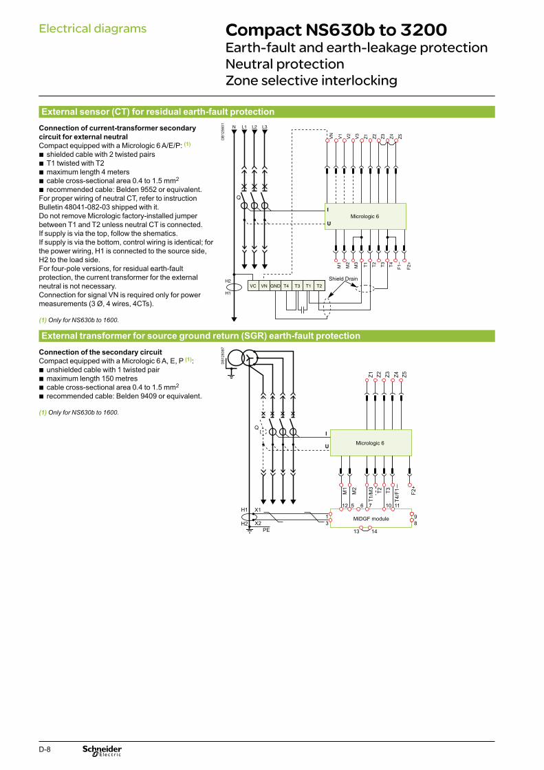
D-8
Compact NS630b to 3200Earth-fault and earth-leakage protection Neutral protectionZone selective interlocking
Electrical diagrams
External sensor (CT) for residual earth-fault protection
Connection of current-transformer secondary
circuit for external neutral Compact equipped with a Micrologic 6 A/E/P: (1)
shielded cable with 2 twisted pairs bT1 twisted with T2 bmaximum length 4 meters bcable cross-sectional area 0.4 to 1.5 mm b 2 recommended cable: Belden 9552 or equivalent. b
For proper wiring of neutral CT, refer to instruction Bulletin 48041-082-03 shipped with it. Do not remove Micrologic factory-installed jumper between T1 and T2 unless neutral CT is connected. If supply is via the top, follow the shematics. If supply is via the bottom, control wiring is identical; for the power wiring, H1 is connected to the source side, H2 to the load side. For four-pole versions, for residual earth-fault protection, the current transformer for the external neutral is not necessary. Connection for signal VN is required only for power measurements (3 Ø, 4 wires, 4CTs).
(1) Only for NS630b to 1600.
DB
1256
01
Shield Drain
External transformer for source ground return (SGR) earth-fault protection
Connection of the secondary circuit
Compact equipped with a Micrologic 6 A, E, P (1):unshielded cable with 1 twisted pair bmaximum length 150 metres bcable cross-sectional area 0.4 to 1.5 mm b 2
recommended cable: Belden 9409 or equivalent. b
(1) Only for NS630b to 1600.
DB
1283
87
Q
Micrologic 6
PE
X1
X2 814
111012 5 6 7
13
931
H1
H2MiDGF module
M1
M2 T3 F2+
T2T1
/M3
T4/F
1
Z1 Z2 Z3 Z4 Z5

D-9
Earth-leakage protection
Connection of the rectangular-sensor secondary
circuit
Compact equipped with a Micrologic 7 A/P: use the cable shipped with the rectangular sensor.
DB
1283
88
Micrologic 7
4Z3Z2Z1Z 5Z
I
Q
M1M2
M3
U
M1
M2 T3 F2+
T2T1
/M3
T4/F
1
L2 L3L1N
Neutral protection
three pole circuit breaker: bneutral protection is impossible with Micrologic A vwith Micrologic E, P, an external neutral transformer v
is necessary; the connection diagram is the same as for residual earth-fault protection.
four pole circuit breaker: bCompact equipped with Micrologic A vthe current transformer for external neutral is not v
necessary.
Zone selective interlocking
Zone-selective interlocking is used to reduce the electrodynamic forces exerted on the installation by shortening the time required to clear faults, while maintaining time discrimination between the various devices.A pilot wire interconnects a number of circuit breakers equipped with Micrologic A/E/P control units, as illustrated in the diagram above.The control unit detecting a fault sends a signal upstream and checks for a signal arriving from downstream. If there is a signal from downstream, the circuit breaker remains closed for the full duration of its tripping delay. If there is no signal from downstream, the circuit breaker opens immediately, regardless of the tripping-delay setting.Fault 1.Only circuit breaker A detects the fault. Because it receives no signal from downstream, it immediately opens in spite of its tripping delay set to 0.3.Fault 2.Circuit breakers A and B detect the fault. Circuit breaker A receives a signal from B and remains closed for the full duration of its tripping delay set to 0.3. Circuit breaker B does not receive a signal from downstream and opens immediately, in spite of its tripping delay set to 0.2.
Wiring Maximum impedance: 2.7 b Ω / 300 m.Capacity of connectors: 0.4 to 2.5 mm b 2.
Wires: single or multicore. bMaximum lenght: 3000 m. bLimits to device interconnection: bthe common ZSI - OUT (Z1) and the output ZSI - OUT (Z2) v
can be connected to a maximum of 10 upstream devicea maximum of 100 downstream devices may be connected v
to the common ZSI - IN (Z3) and to an input ZSI - IN CR ( Z4) or GF (Z5).
Downstreamcircuit break
Fault 1
Fault 2
Upstreamcircuit break tsd = 0.3
tsd = 0.2
A
B
Compact NS630b to 3200Earth-fault and earth-leakage protection Neutral protectionZone selective interlocking
Electrical diagrams

D-10
Electrical diagrams
Connection of circuit breakers to the Modbus communication network
DB
4015
96Compact NS630b to 3200 Communication
40
100%
%
Ø5...8
manuauto
40
100%
%
24 V c
Compact NSX160+ BSCM
Compact NSX400 + BSCM+ communicating motor mechanism
Compact NSX160
Compact NS630b(fixed device)
Masterpact NT(withdrawable device)
3
1 2
4
5
Ethernet
6
7 7
8
9
9
10 10
Modbus 24 V c
1 External 24 V c power supply module (AD)2 Ethernet gateway (EGX100)3 Modbus Communication Interface Module
(TRV00210) with stacking accessory (TRV00217)
4 Modbus network5 ULP cable6 FDM121 display (TRV00121)7 Compact NSX cord (LV434200, LV434201,
LV434202)8 Modbus CCM “chassis”9 Breaker ULP cord (LV434195, LV434196,
LV434197)10 Modbus BCM ULP “device”

D-11
DB
4022
11
Ethernet
customer terminal block
24 V0 V
D0
D1
CCMCCM
+ -
+ -
Breaker ULPcord
A B A' B'
A B A' B'
24 V0 V
D0
D1
24 V0 V
D0
D1
Rx- Rx+ Tx- Tx+EGX100
Modbus linetermination(VW3A8306DRC)
+ -
Modbus Communication Interface Module (Compact NSX)
-
External power supply24 V c+
blue
F1-0 V 24 V
VN F2+
FDM121version > V2.0.2
+ -FDM121version > V2.0.2
+ -
Breaker ULPcord
white
The configuration is only possiblewith CCM marked Schneider Electric on the front face.
Micrologic P
Micrologic EModbus
Com
Address
Baud-rate19.2 k
4W, 2W+ULP
2w+ULP
w
Modbus RS 485 2-wire + ULP
black redbluewhiteblackred
F2+F1-M3M2M1T4T3T2T1Z5Z4Z3Z2Z1
Micrologic
E1E2E3E4E5 E6
E1 E2 E3 E4 E5 E6
BCM ULP
D1
+ D0
B' / R
x+ B
/ Tx
- A
' / Rx-
A / Tx
D1
D0
0 V
24 V
E1 E2 E3 E4 E5 E6
customer terminal block
D1
+ D0
B' / R
x+ B
/ Tx
- A
' / Rx-
A / Tx
D1
D0
0 V
24 VN
etwork
Breaker
Electrical diagrams Compact NS630b to 3200 Communication

D-12
Fixed, manually operated Compact NS
DB
4020
82
ModbusCom
Address
Baud-rate19.2 k
4W, 2W+ULP
2w+ULP
ModbusCom
Address47
Baud-rate19.2 k
4W, 2W+ULP
4wires
Micrologic P
Micrologic Ew
Micrologic P
Micrologic Ew
E1 E2 E3 E4 E5 E6
Modbus RS 485 2-wirewithout ULP module
Modbus RS 485 2-wire + ULP with ULP module
Rx- Rx+ Tx-EGX100
Modbus RS 485 4-wirewithout ULP module
+ -
+ -
External power supply24 V c
B’ / R
x + D1
A’ / Rx - D
0
B / Tx + D
1
A / Tx - D0
0 V
24 V
E1 E2 E3 E4 E5 E6
BCM ULP
Rx- Rx+ Tx- Tx+Tx+
B’ / R
x + D1
A’ / Rx - D
0
B / Tx + D
1
A / Tx - D0
0 V
24 V
E1 E2 E3 E4 E5 E6
EGX100+ -
+ -
External power supply24 V c
BCM ULP
Rx- Rx+ Tx- Tx+
B’ / R
x + D1
A’ / Rx - D
0
B / Tx + D
1
A / Tx - D0
0 V
24 V
E1
red black blue
E2 E3 E4 E5 E6
EGX100+ -
+ -
External power supply24 V c
BCM ULP
FDM121version > V2.0.2
+ -
E1 E2 E3 E4 E5 E6
E1 E2 E3 E4 E5 E6
white
Breaker ULPcord
Fixed, electrically operated Compact NS
DB
4020
84
ModbusCom
Address
Baud-rate19.2 k
4W, 2W+ULP
2w+ULP
ModbusCom
Address47
Baud-rate19.2 k
4W, 2W+ULP
4wires
Micrologic P
Micrologic Ew
Micrologic P
Micrologic Ew
Modbus RS 485 2-wirewithout ULP module
Modbus RS 485 2-wire + ULP with ULP module
Rx- Rx+ Tx-EGX100
Modbus RS 485 4-wirewithout ULP module
+ -
+ -
External power supply24 V c
B’ / R
x + D1
A’ / Rx - D
0
B / Tx + D
1
A / Tx - D0
0 V
24 V
E1 E2 E3 E4 E5 E6
Customer terminal block
Rx- Rx+ Tx- Tx+Tx+
B’ / R
x + D1
A’ / Rx - D
0
B / Tx + D
1
A / Tx - D0
0 V
24 V
E1 E2 E3 E4 E5 E6
EGX100+ -
+ -
External power supply24 V c
Customer terminal block
Rx- Rx+ Tx- Tx+
B’ / R
x + D1
A’ / Rx - D
0
B / Tx + D
1
A / Tx - D0
0 V
24 V
E1
red black blue
E2 E3 E4 E5 E6
EGX100+ -
+ -
External power supply24 V c
Customer terminal block
FDM121version > V2.0.2
+ -
white
Breaker ULPcord
Electrical diagrams Compact NS630b to 3200 fixedWiring of the COM option (Modbus BCM ULP Module) with or without ULP module

D-13
Withdrawable Compact NS630b to 3200 Wiring of the COM option (Modbus BCM ULP and CCM modules) with or without ULP module
Modbus RS 485 2-wirewithout ULP module
Modbus RS 485 4-wirewithout ULP module
Modbus RS 485 2-wire + ULPwith ULP module
E1 E2 E3 E4 E5 E6
Customer terminal block
Rx- Rx+ Tx- Tx+
B’ / R
x + D1
A’ / Rx - D
0
B / Tx + D
1
A / Tx - D0
0 V
24 V
EGX100+ -
CCM
+ -
+ -
+ -
External power supply24 V c
A B A’ B’
A B A’ B’
Micrologic P
Micrologic EModbus
ComAddress
Baud-rate19.2 k
4W, 2W+ULP
2w+ULP
w
E1 E2 E3 E4 E5 E6
Customer terminal block
Rx- Rx+ Tx- Tx+B
’ / Rx + D
1
A’ / Rx - D
0
B / Tx + D
1
A / Tx - D0
0 V
24 V
EGX100+ -
+ -
External power supply24 V c
CCM
A B A’ B’+ -
+ -A B A’ B’
FDM121version > V2.0.2
E1 E2 E3 E4 E5 E6
customer terminal block
CCMCCM
+ -
Rx- Rx+ Tx- Tx+
B’ / R
x + D1
A’ / Rx - D
0
B / Tx + D
1
A / Tx - D0
0 V
24 V
EGX100+ -
+ -
External power supply24 V c
+ - + -
A B A’ B’
red black bluewhite
Breaker ULPcord
A B A’ B’
ModbusCom
Address47
Baud-rate19.2 k
4W, 2W+ULP
4wires
Micrologic P
Micrologic Ew
This configuration is only possible with CCM marked Schneider Electric on the front face.
Netw
orkB
reaker
Netw
orkB
reaker
Netw
orkB
reaker
DB
4014
77
Electrical diagrams
Withdrawable Compact NS

D-14
Compact NS630b to 3200Connection of the 24 V DC external power supply AD module
Electrical diagramsD
B12
8383
The 24 V DC external power-supply (AD module) for the Micrologic control unit b(F1- F2+) is not required for basic protections LSIG.
The 24 V DC external power-supply (AD module) for the BCM ULP bcommunication module (E1-E2) is required.
The 24 V DC external power-supply (AD module) for the FDM121 front display bmodule (0V +24) is required.
The 24 V DC external power-supply (AD module) for the programmable contact bM2C/M6C is required.
The same 24 V DC external power-supply (AD module) can be connected bto Micrologic control unit, BCM ULP and FDM121, M2C/M6C.
b If voltage > 480 V AC or in an environment with a high level of electromagnetic disturbances, use separate power supply: 1 power supply for Micrologic (F1- F2+) and M2C/M6C, another power supply for BCM ULP and FDM121.
With Micrologic A/E, it is recommended to connect 24 V DC external power-supply b(AD module) to the Micrologic control unit (F1- F2+) in order to keep available the display and the energy metering, even if Current < 20 % In.
Note: In case of using the 24 V DC external power supply (AD module), maximum cable length between 24 V DC (G1, G2) and the control unit (F1-, F2+) must not exceed 10 meters.The BAT battery module, mounted in series upstream of the AD module, ensures an uninterrupted supply of power if the AD module power supply fails.The internal voltage taps are connected to the botton side of the circuit breaker.With Micrologic P/H, external voltage taps are possible using the PTE option. With this option, the internal voltage taps are disconnected and the voltage taps are connected to terminals VN, V1, V2, V3.The PTE option is required for voltages less than 220 V and greater than 690 V (in which case a voltage transformer is compulsory). For three-pole devices, the system is supplied with terminal VN connected only to the control unit (Micrologic P).When the PTE option is implemented, the voltage measurement input must be protected against short-circuits. Installed as close as possible to the busbars, this protection function is ensured by a P25M circuit breaker (1 A rating) with an auxiliary contact (cat. no. 21104 and 21117). This voltage measurement input is reserved exclusively for the control unit and must not ever be used to supply other circuits outside the switchboard.
Connection
The maximum length for each conductor supplying power to the trip unit or M6C module is 10 m.Do not ground F2+, F1-, or power supply output:
the positive terminal (F2+) on the trip unit must not be connected to earth ground bthe negative terminal (F1-) on the trip unit must not be connected to earth ground bthe output terminals (- and +) of the 24 V DC power supply must not be grounded. b
Reduce electromagnetic interference:
the input and output wires of the 24 V DC power supply must be physically bseparated as much as possible
if the 24 V DC power supply wires cross power cables, they must cross bperpendicularly. If this is not physically possible, the power supply conductors must be twisted together
Power supply conductors must be cut to length. Do not loop excess conductor. b

E-1
Compact NS630b to 3200 Additional characteristicsContents
Presentation 2Functions and characteristics A-1Installation recommendations B-1Dimensions and connection C-1
Tripping curves E-2Compact NS630b to 3200 E-2
Current-limiting curves E-3

E-2
Tripping curvesCompact NS630b to 3200
Micrologic electronic control units
Options for Micrologic electronic control units
(1)Ig = In x… A B C D E F G H J
Ig < 400 A 0.3 0.3 0.4 0.5 0.6 0.7 0.8 0.9 1400 A y Ig y 1200 A 0.2 0.3 0.4 0.5 0.6 0.7 0.8 0.9 1Ig > 1200 A 500 640 720 800 880 960 1040 1120 1200
DB
1283
95
Micrologic 5.0, 6.0, 7.0Micrologic 2.0
Earth-fault protection (Micrologic 6.0)
DB
1283
97
0.40.30.20.10
I²t ON
I²t OFF
DB
1283
96
Additional characteristics

E-3
Current-limiting curves
Ics = 100 % IcuThe exceptional limiting capacity of the Compact NS range greatly reduces the forces created by fault currents in devices.The result is a major increase in breaking performance. In particular, the service breaking capacity Ics is equal to 100% of Icu.The Ics value, defined by IEC standard 60947-2, is guaranteed by tests comprising the following operations:
break three times consecutively a fault current equal to 100 % of Icu bcheck that the device continues to function normally: bit conducts the rated current without abnormal temperature rise vprotection functions perform within the limits specified by the standard vsuitability for isolation is not impaired. v
Longer service life of electrical installationsCurrent-limiting circuit breakers greatly reduce the negative effects of short-circuits on installations.Thermal effects
Less temperature rise in conductors, therefore longer service life for cables.Mechanical effects
Reduced electrodynamic forces, therefore less risk of electrical contacts or bus bars being deformed or broken.Electromagnetic effects
Less disturbances for measuring devices located near electrical circuits.
Economy by means of cascadingCascading is a technique directly derived from current limiting. Circuit breakers with breaking capacities less than the prospective short-circuit current may be installed downstream of a limiting circuit breaker. The breaking capacity is reinforced by the limiting capacity of the upstream device.It follows that substantial savings can be made on downstream equipment and enclosures.
Current-limiting curvesThe current-limiting capacity of a circuit breaker is expressed by two curves which are a function of the prospective short-circuit current (the current which would flow if no protection devices were installed):
the actual peak current (limited current), bthermal stress (A b 2s), i.e. the energy dissipated by the short-circuit in a conductor
with a resistance of 1 Ω.Example
What is the real value of a 200 kA rms prospective short-circuit (i.e. 440 kA peak) limited by an NS630bLB upstream ?Answer: 70 kA peak (see next page).
The limiting capacity of a circuit breaker is its aptitude to limit short-circuit currents.
The exceptional limiting capacity of the Compact NS range is due to the rotating double-break technique (very rapid natural repulsion of contacts and the appearance of two arc voltages in-series with a very steep wave front).
E28
800
(t)
ProspectiveIsc peak
(Isc)
Prospectivecurrent
ProspectiveIsc
Limited Iscpeak
Actualcurrent
LimitedIsc

E-4
(1) Valid for 480 V Nema.
Limited short-circuit current (k peak)
Current-limiting curves
Voltage 660/690 V AC
DB
1284
00
kÂ
NS1600bNNS2000NNS2500NNS3200N
NS630bLNS800LNS1000L
NS630bHNS800HNS1000HNS1250HNS1600HNS630bN
NS800NNS1000NNS1250NNS1600N NS630bLB
NS800LB
NSX630L
L
NSX400
NSX250NSX100NSX160
S
S
H
F, N
FN, H
Rated short-circuit current (kA rms)
Limited energy
Thermal-stress curves
Voltage 660/690 V AC
DB
1284
02
NS1600bNNS2000NNS2500NNS3200N
NS630bLNS800LNS1000L
NS630bHNS800HNS1000HNS1250HNS1600H
NS630bNNS800NNS1000NNS1250NNS1600N
NS630bLBNS800LB
N, H
HNSX630
NSX400
NSX250
NSX100NSX160
L
L
S
S
F, N
F
Rated short-circuit current (kA rms)
Limited short-circuit current (k peak)
Voltage 400/440 V AC (1)
DB
1283
99
kÂ
NS630bLNS800LNS1000L
NS630bHNS800HNS1000HNS1250HNS1600HNS630bN
NS800NNS1000NNS1250NNS1600N
NS630bLBNS800LB
NSX630LSH
NF LS
HN
FB
NSX400
NSX250NSX100NSX160
Rated short-circuit current (kA rms)
Limited energy
Voltage 400/440 V AC (1)
DB
1284
01
NS630bHNS800HNS1000HNS1250HNS1600H
NS630bNNS800NNS1000NNS1250NNS1600N
NS630bLBNS800LB
NS1000LNS630bLNS800L
B
NSX630NSX400
NSX250NSX100NSX160
LSHF N
LSHF N
Rated short-circuit current (kA rms)
Current-limiting curvesAdditional characteristics


Nationwide support on one number -
0870 608 8 608Fax 0870 608 8 606
As a global specialist in energy management with operations in more than 100 countries, Schneider Electric offers integrated solutions across multiple market segments, including leadership positions in energy and infrastructure, industrial processes, building automation, and data centres/networks, as well as a broad presence in residential applications.
Focused on making energy safe, reliable, and efficient, the company’s 110,000 plus employees achieved sales of 19.6 billion euros in 2010, through an active commitment to help individuals and organizations “Make the most of their energy.”
We are changing our brand names and becoming one Schneider Electric. You’ll get the same great quality products, but from one name you can remember and trust. This provides you and your customers with the reassurance associated with Schneider Electric.
Some of our market leading brands have already become Schneider Electric including Merlin Gerin, Telemecanique, Square D, GET, Mita, Sarel, Himel, Thorsman, Tower and TAC.
Working as one Schneider Electric makes it clearer that our ranges are highly compatible for integrated solutions.
Schneider Electric Ltd
United KingdomStafford Park 5, TelfordShropshire TF3 3BLTel: 0870 608 8 608Fax: 0870 608 8 606www.schneider-electric.co.uk
IrelandHead office, Block aMaynooth Business CampusMaynooth, Co. KildareTel: (01) 601 2200Fax: (01) 601 2201www.schneider-electric.ie
As standards, specifications and designs change from time to time, please ask for confirmation of the information given in this publication S
E72
70 J
UN
201
1
member of
.co.uk