low voltage ac drives abb industrial drives acs880, drive ... · tÜv-certified safety design tool...
TRANSCRIPT

— LOW VOLTAGE AC DRIVES
ABB industrial drivesACS880, drive modules0.75 to 3500 HP (0.55 to 3200 kW)

— Reliability, performance and safety. ACS880 series.

—ABB industrial drivesACS880, drive modules
AACS880 DRIVE SERIES4 – 17
E
SINGLE DRIVE MODULES AND MODULE PACKAGES23 – 28
BHOW TO SELECT A DRIVE18
FREGENERATIVE DRIVE MODULES29 – 34
CTECHNICAL DATA19
G
ULTRA-LOW HARMONIC DRIVE MODULES35 – 40
IDIMENSIONS54 – 58
D
WALL-MOUNTED SINGLE DRIVE MODULES20 – 22
H
MULTIDRIVE MODULES41 – 53
JSTANDARD INTERFACE AND EXTENSIONS59 – 60
K
OPTIONS61 – 79
LMOTORS 80 – 81
M
ABB DRIVE SERVICES82 – 83
N
ABB AUTOMATION PRODUCTS
84 – 86
O
SUMMARY OF FEATURES AND OPTIONS87 – 94
4 TH E A LL- CO M PATI B LE AC S 8 8 0 S E R I E S6 S I M PL I F Y YO U R WO R L DW ITH O U T L I M IT I N G YO U R P OSSIB I L IT I E S
8 O P TI M IZED FO R C A B I N E T A SSEM B LY
9 E A SE O F EN G I N EER I N G A N D USE
10 V I RT UA L CO M M ISSI O N I N G
11 SM A RTER SO LU TI O NS W ITH D R I V E- B A SED FU N C TI O N A L S A FE T Y
1 2 CO M PR EH ENSI V E CO N N EC TI V IT Y
1 3 M I N I M IZED D OW NTI M E
1 4 G LO B A L CO M PATI B I L IT Y W ITH
1 4 VA R I O US D EM A N DS
1 5 PR EM I U M CO NTR O L A N D
1 5 PR O G R A M M A B I L IT Y
16 A PPL I C ATI O N - A N D I N D US TR Y-SPECI FI C SO LU TI O NS
1 8 H OW TO S E LEC T A D R I V E
19 TECH N I C A L DATA
2 0 WA LL- M O U NTE D S I N G LE D R I V E M O D U LE S
2 4 S I N G LE D R I V E M O D U LE S H I G H P OW E R S I N G LE D R I V E
2 9 R EG E N E R ATI V E D R I V E M O D U LE S
3 5 U LTR A - LOW H A R M O N I C D R I V E M O D U LE S
4 1 A I R- CO O LE D M U LTI D R I V E M O D U LE S LI Q U I D - CO O LE D M U LTI D R I V E M O D U LE S
5 4 D I M E N S I O N S
O P TI O N S59 S TA N DA R D I NTER FACE A N D E X TENSI O NS
59 FO R PLU G - I N CO N N EC TI V IT Y
61 CO NTR O L PA N EL O P TI O NS
6 2 A B B SM A RTPH O N E A PP S
6 3 CO N N EC TI V IT Y TO AU TO M ATI O N S Y S TEMS
6 4 FEED B ACK I NTER FACE A N D D D C S CO M M U N I C ATI O N O P TI O NS
6 5 R EM OTE M O N ITO R I N G O P TI O NS
6 6 P C TO O L O P TI O NS
6 7 S A FE T Y O P TI O NS
6 9 EM C – EL EC TR O M AG N E TI C CO M PATI B I L IT Y
7 1 S IN E FILTER S
7 2 B R A K E O P TI O NS
7 7 D U/DT FI LTER S
8 0 CH O O S E TH E R I G HT M OTO R FO R YO U R A PPLI C ATI O N
A B B D R I V E S E RV I CE S8 2 K EEP YO U R PR O CE SS R U N N I N G
8 4 A B B A B I L IT Y ™ D I G ITA L P OW ERTR A I N
8 7 S U M M A RY O F F E ATU R E S A N D O P TI O N S

Typical industries
Food and beverageMaterial
handling
Mining and minerals
Oil and gas
MarinePower plants
Sawmill
Automotive
Rubber and plastics
Chemical
ABB’s all-compatible drives are designed to provide customers across industries and applications with unprecedented levels of compatibility and flexibility. The ACS880 drive modules are optimized for panel building. They are customized to meet the particular needs of specific industries, such as oil and gas, mining, metals, chemicals, cement, power plants, material handling, pulp and paper, sawmills, marine, water and wastewater, food and beverage, and automotive. They can control a wide range of applications, including cranes, extruders, winches, winders, conveyors, mixers, compressors, centrifuges, test benches, elevators, extruders, pumps and fans.
—High quality
Reliability and consistent high qualityThe ACS880 drives are designed for customers who value high quality and robustness in their applications. They have coated boards as standard, making the ACS880 suitable for harsh conditions. Additionally, every ACS880 drive is factory-tested at full load to ensure maximum reliability. The tests include performance and all protective functions.
High performance, safety and configurabilityThe ACS880 offers the highest level of performance. The drives are equipped with ABB’s signature Direct Torque Control (DTC), which provides precise speed and torque control for all applications and supports virtually any type of motor.
The extensive ACS880 offering includes wall-mounted drives, drive modules and cabinet-built drives, as well as low harmonic and regenerative variants.
The ACS880 has all the essential features built-in reducing the time required for engineering, installation and commissioning. A wide range of options are also available to optimize the drive for different requirements, including certified, integrated safety features.
—The all-compatible ACS880 seriesReliability and flexibility
The AC880 is an all-compatible ABB industrial drive, offered in a range of wall-mounted drives, drive modules and cabinet-built drives.
4 A B B I N D U S TR I A L D R I V E S , AC S 8 8 0 D R I V E M O D U L E S , C ATA LO G
A

A

6 A B B I N D U S TR I A L D R I V E S , AC S 8 8 0 D R I V E M O D U L E S , C ATA LO G
A
—Simplify your world without limiting your possibilities
The ACS880 industrial drive modules are designed for cabinet installation, with optimized location of the power terminals and wheels for easy maneuvering. A wide selection of module variants and options, including extensive programming and connectivity, make the ACS880 suitable for various different requirements and applications.
Ease of engineering and use• All-compatible ACS880 drives share the same easy-to-
use user interface• Multilingual control panel with clear display• Graphical PC tools for engineering, commissioning and
maintenance• Minimized engineering and installation effort with
integrated features and components• Extensive selection of support material and tools for
engineering• Virtual commissioningSee page 09 – 10
Optimized for cabinet assembly• Flexible mounting directions and product configurations• Side-by-side mounting• Power terminal locations designed for optimal and
compact cabinet layout• High power modules with wheels for easy maneuvering• Possibility for flange (push through) mounting• Mechanical kits for easy cabinet assemblySee page 08
Comprehensive connectivity• Communication with all major automation networks • Remote monitoring • Mobile connectivity• Integration tools for various PLCsSee page 12
Smarter solutions with drive-based functional safety• Safe Torque Off built-in as standard• Optional safety modules for extended safety functions• Encoderless safe speed detection• Highest level of machinery safety, SIL 3 / PL e• TÜV certifiedSee page 11

7SI M PL I F Y YO U R WO R L D W ITH O U T L I M IT I N G YO U R P OSSI B I L IT I E S
A
Premium control and programmability• Direct Torque Control (DTC) for precise control• Speed, torque and position control as well as
synchronizing• Extensive parameter-based programming• Adaptive programming as standard• Drive-based PLC programmability (IEC 61131-3) for
fully customized solutionsSee page 15
Minimized downtime• Robust, long lifetime design for maximum reliability• Coated circuit boards for harsh conditions• Removable memory unit for fast drive replacement • Each drive factory tested at full load• Nine-year maintenance interval• Worldwide service and support• Advanced features for analyzing and resolving issuesSee page 13
Global compatibility with various demands• Global product approvals, e.g. CE, UL, cUL, CSA,
marine certifications, ATEX• Support for various motor types• Low harmonic content• Capable of power regenerationSee page 14
Application and industry specific solutions• Ready-made optimized solutions for various
applications and industriesSee page 16 – 17
—Nine-year maintenance interval

8 A B B I N D U S TR I A L D R I V E S , AC S 8 8 0 D R I V E M O D U L E S , C ATA LO G
A
—Optimized for cabinet assembly
Optimized mechanical design for cabinet assemblyACS880 drive modules have been optimized for assembly into the customer’s own cabinets to ensure high quality and compact installation at minimal cost. High power modules have wheels for easy maneuvering, and the power terminal locations have been designed for optimal and compact cabinet layout. Side-by-side mounting reduces the required cabinet space.
For harsh environments, flange mounting (push through) with UL (NEMA) Type 12 / IP55 back side protection is offered for complete drive modules. In flange mounting, the control electronics are separated from the cooling airflow for better thermal management and higher reliability.
Flexible mounting and cabling directions enable adaptation to various cabinet enclosures. All the complete ACS880 drive modules have UL (NEMA) Type Open / IP20 enclosure class to minimize engineering and assembly effort, as well as to reduce the total cost and ensure a safe ready-made cabinet.
Support for cabinet assemblyA large variety of support material is available for making cabinet assembly, planning, and implementation as straightforward and rapid as possible. Cabinet assembly accessories help shorten engineering and assembly time, and help to reduce the risk of errors.
A wide selection of both mechanical and electrical installation accessories are offered for high power modules. These accessories are available allowing full design to install the modules into customer enclosures. Additionally, ABB authorized and registered system integrators and panel builders can offer their assistance.

9TH E A L L- CO M PATI B L E AC S 8 8 0 D R I V E SER I E S
ADriveSize sizing tool for selecting the optimal driveDriveSize is designed to help select the optimal drive, motor and transformer for the application. Based on data supplied by the user, the tool calculates and suggests which drive and motors to use. DriveSize is a free software and can be used either online or downloaded for PC from https://new.abb.com/drives/software-tools/drivesize.
Choke
Safety functions
Modbus RTU interface
EMC filter
Extensive I/O
Up to IP55 enclosure classBrake chopper
Direct torque control
—Ease of engineering and use
All-compatible user interface saves commissioning and learning timeThe ACS880 is part of ABB’s all-compatible drives portfolio. Other drives in this portfolio are the ACS380, ACS480 and ACS580.
These drives share the same easy-to-use PC tools and multilingual control panels. To further enhance the user experience they also have the same parameter structure, saving learning and commissioning time.
The drives also share the same communication option modules, simplifying the use of the drives and spare parts required.
Simplicity at your fingertips as standardThe control panel’s assistant helps you setup the drive quickly and effectively. The intuitive, high-contrast, high-resolution display offers easy navigation in multiple languages.
The PC tool for commissioning and configuration provides extensive drive monitoring capabilities, quick access to drive settings, as well as a graphical interface for configuring safety functions, visual control diagrams, and direct links to user manuals.
Built-in features simplify ordering and installationAll ACS880 drives have an internal choke for harmonic filtering, a Modbus RTU fieldbus interface, and Safe Torque Off functionality as standard. Other built-in features, standard or optional, include EMC filters, brake choppers, du/dt filters, low harmonic or regenerative functionality, various I/O extensions, communication protocol adapters, and functional safety modules.
The built-in features shorten engineering and installation time as well as reduce the risk of errors. As a result, the total cost is lower and the whole drive system is more compact.
Engineering supportABB provides an extensive selection of support material and tools to help in engineering, such as:• Drive sizing tools, e.g. DriveSize• Step-by-step installation instructions• E-learning• Safety circuit design tools• EPLAN P8 macros• Selection tool for choosing external components,
e.g. fuses and circuit breakers• Dimensional (2D and 3D) and electrical drawings• Application guides• Drive installation and configuration videos
These tools and support from our experts ensure that the drive system can be set up easily and reliably.

10 A B B I N D U S TR I A L D R I V E S , AC S 8 8 0 D R I V E M O D U L E S , C ATA LO G
A
—Virtual commissioning
Virtual engineering and commissioning allows machine builders and system integrators to develop and simulate entire industrial processing lines and machines, including ABB drives, without actually running the hardware. This gives valuable benefits in the phases of designing, commissioning and operating machines.
Design safely and efficientlyEngineers can start configuring and programming drives well before receiving them from ABB because the PC software tool, Drive Composer Pro, can be used with virtual and real drives. Virtualization can include the kinematic and physical behavior of the machine and the overriding automation. Virtual drives can also be used with the ABB Robot Studio tool and ABB Automation Builder programming tools to build more complete virtual machines and processing lines.
After deploying the virtual machine in use on-site, any future improvements can be virtually tested before implementing them in the process. This all supports safety and quality in the engineering process.• Find and solve potential problems earlier• Save time and money due to faster drive
commissioning• Assist the sizing and energy optimization of
electromechanical drive systems
BenefitsThroughout the value chain, from sales, marketing, and training to field engineering and product development, virtual commissioning makes drive applications more easily understood and helps to:• Design, test and learn drive applications virtually
with the same software tools used with the actual hardware
• Train users and engineers with application simulation
• Tune drive parameters easily off-site before going into more demanding on-site testing
—Save time, reduce risk, and increase engineering productivity

11TH E A L L- CO M PATI B L E AC S 8 8 0 D R I V E SER I E S
A
—Smarter solutions with drive-based functional safety
Maximized safety and conformityThe Safe Torque Off (STO) safety function comes integrated into ACS880 drives. Optional safety functions modules provide an easy way to extend safety functions. These plug-in modules are installed and cabled inside the drive, enabling safety functions and diagnostics in one compact and reliable module. The safety functions are certified by TÜV Nord and comply with the highest performance requirements in machinery safety – SIL 3 / PL e *).
Increased productivity by doing things smarterSafety functions help to minimize unnecessary downtime by keeping the application in control at all times. For example, Safely-Limited Speed (SLS) can keep your process running under safe conditions rather than completely stopping it.
Flexibility and ease of useThe safety functionality can be scaled to your needs. Ranging from Safe Torque Off (STO) wired to an emergency stop push button, or a complete safety system with PROFIsafe and a safety PLC, e.g. the AC500-S.
Configuring the safety functions module is easy thanks to the graphical user interface in the Drive Composer pro PC tool.
Available safety functionalityThe following safety functions are supported:• Safe Torque Off (STO)• Safe stop 1 (SS1-t and SS1-r) • Safe stop emergency (SSE)• Safe brake control (SBC)• Safely-limited speed (SLS)• Safe maximum speed (SMS)• Prevention of unexpected startup (POUS) • Safe direction (SDI)• Safe speed monitor (SSM)• Safe motor temperature (SMT)
—Integrated safety simplifies configuration
Safety for explosive atmospheresACS880 and ABB Ex motors have been certified as a package providing a safe, proven solution for explosive atmospheres. ACS880 safety options for ATEX environments include: • ATEX-approved thermistor protection module• ATEX-approved safe torque off
TÜV-certified safety design toolThe FSDT-01 functional safety design tool can be used to design complete safety circuits. With this tool it is possible to define required safety integrity (SIL) / performance level (PL) for safety functions, verify achieved safety level and generate design reports.
*) SIL 2 / PL c for SMT, safe motor temperature.
12 A B B I N D U S TR I A L D R I V E S , AC S 8 8 0 D R I V E M O D U L E S , C ATA LO G
A
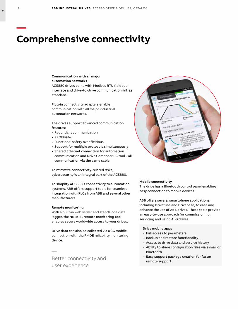
—Comprehensive connectivity
Communication with all majorautomation networksACS880 drives come with Modbus RTU fieldbus interface and drive-to-drive communication link as standard.
Plug-in connectivity adapters enable communication with all major industrial automation networks. The drives support advanced communication features:• Redundant communication• PROFIsafe• Functional safety over fieldbus• Support for multiple protocols simultaneously• Shared Ethernet connection for automation
communication and Drive Composer PC tool – all communication via the same cable
To minimize connectivity-related risks, cybersecurity is an integral part of the ACS880.
To simplify ACS880's connectivity to automation systems, ABB offers support tools for seamless integration with PLCs from ABB and several other manufacturers.
Remote monitoringWith a built-in web server and standalone data logger, the NETA-21 remote monitoring tool enables secure worldwide access to your drives.
Drive data can also be collected via a 3G mobile connection with the RMDE reliability monitoring device.
—Better connectivity and user experience
Mobile connectivityThe drive has a Bluetooth control panel enabling easy connection to mobile devices.
ABB offers several smartphone applications, including Drivetune and Drivebase, to ease and enhance the use of ABB drives. These tools provide an easy-to-use approach for commissioning, servicing and using ABB drives.
Drive mobile apps• Full access to parameters• Backup and restore functionality• Access to drive data and service history• Ability to share configuration files via e-mail or
Bluetooth• Easy support package creation for faster
remote support

13TH E A L L- CO M PATI B L E AC S 8 8 0 D R I V E SER I E S
A
—Minimized downtime
Advanced features for analyzing and resolving issuesThe ACS880 has timers and counters that can be configured to remind you when the drive or process equipment needs maintenance.
Accurate and reliable diagnostic information is available for warning and fault messages. Help texts give detailed information about the warning or fault. Data loggers store critical values before and during an event. The real-time clock allows you to see the exact times of events.
For faster remote support, all relevant drive data and changed parameters can be saved in a single file package that you can easily create with the Drive Composer PC tool or by creating a QR code with the control panel.
Global supportABB offers worldwide support via its extensive pre- and post-sales network, structured to make sure that you have the experts you need close by, locally and globally. See pages 82-83.
Robust, long life time designThe ACS880 is designed to last for a long time, even in harsh conditions. The benefits include a nine-year maintenance interval and good tolerance for vibrations and contamination.
Several design features make the ACS880 a safe choice:• Coated circuit boards• Minimized airflow through the control
board section• Designed for ambient temperatures up
to 55 °C• Advanced protections – e.g. faster and
more accurate IGBT protection using a thermal model
Each ACS880 drive unit is tested in the factory at full load to ensure maximum reliability. Continuous quality improvements are made based on the results of accelerated lifetime testing.
Removable memory unitThe memory unit stores the drive software and settings, including motor data. This unit can be switched from one drive to another, allowing simple and rapid drive replacement without any special equipment, software loading, parameter settings, or other adjustments in the drive or automation system. It also eliminates the risk of software incompatibility. The new drive is ready to run as soon as the memory unit is plugged in.
—Nine-year maintenance interval

14 A B B I N D U S TR I A L D R I V E S , AC S 8 8 0 D R I V E M O D U L E S , C ATA LO G
A
—Global compatibility with various demands
Global product approvalsThe ACS880 is a global product and has all the major global approvals, including CE, UL, cUL, EAC, RCM and TÜV. Marine approval, ATEX and SEMI F47 are available either as standard or as an option.
Support for different motor typesThe ACS880 provides reliable control for squirrel cage, high-torque or servo-type permanent magnet, synchronous reluctance (SynRM), submersible and high-speed motors. Most encoder types are supported.
Regardless of the motor type, drive commissioning is easy, with no need for laborious manual tuning.
Low harmonic contentAll ACS880 drives have an internal choke for harmonic reduction. If lower harmonic content is needed, an ultra-low harmonic variant is available.The drive will produce exceptionally low harmonic content and meet the requirements IEEE519, IEC61000-3-12 and G5/4.
Regeneration of energyThe ACS880 offers a number of solutions for applications where electrical braking is needed. As standard, ACS880 drives have a flux braking feature that provides greater deceleration by increasing the motor flux. If this is not sufficient, the internal brake chopper can be used together with a brake resistor.
The most advanced solution is the ACS880 regenerative drive, which allows full, continuous braking and can produce remarkable energy savings.
ACS880 also supports common DC bus configurations, where the braking energy from one load can be utilized by other loads.

15TH E A L L- CO M PATI B L E AC S 8 8 0 D R I V E SER I E S
A
—Premium control and programmability
Direct Torque Control (DTC)ABB's state of the art motor control technology provides precise speed and torque control, with or without an encoder, even close to zero speed. DTC provides reliable starts and rapid reactions to load or line changes, and ensures smooth and continuous operation. DTC provides optimal control, even with sine filters.
The energy optimizer feature maximizes motor efficiency by ensuring maximum torque per ampere, reducing the power drawn from the supply.
Position control and synchronizingPosition control allows to meet motion systems demands without the need of an external position controller. The ready-made motion functions can be easily configured by parameters.
Additional features, such as built-in synchronized drive to drive link and possibility for encoderless positioning, make ACS880 position control ideal for any axis.
Drive programmingTo meet your specific application needs, you can customize your ACS880 with an extensive range of user-definable software settings (parameters) and adaptive programming.
This makes fine-tuning the ready-made application control program easy. For further customization, drive application programming based on IEC 61131 standard is available for full PLC programmability. IEC programming uses the same programming environment as ABB PLCs. It is also easy to integrate the ACS880 with PLCs and HMIs.
Adaptive programming is an easy to use dynamic programming which allows flexible adjustments to the ACS880 software.
IEC programming based on IEC 61131 standard for full scale PLC programmability is available as an option.

16 A B B I N D U S TR I A L D R I V E S , AC S 8 8 0 D R I V E M O D U L E S , C ATA LO G
A
Cranes (EOT cranes), +N5050• Mechanical brake control• Slow down and end limit logic• Anti-sway• Hoist speed optimization• Shaft synchro
—Application- and industry-specific solutions
Tower cranes, +N5650• Slew control• Mechanical brake control• Mobile access via Bluetooth
Winches, +N5100• Mooring• Anchor control• Accurate open loop speed & torque control• Winch interface for multiple control stands
Winders, +N5000• Roll diameter calculation• Tension control• Dancer and load cell control• Inertia and friction compensation
Artificial oil lifting, ESP, +N5600• Submersible motor control (induction and
PM motors)• Motor temperature minimization• Backspin speed observer• Rocking start• Flow calculation
Artificial oil lifting, PCP +N5200• Backspin control• Automatic pump speed control• Induction and PM motor control• Protections for pump mechanics
Artificial oil lifting, rod pump +N5250• Optimization of the pump speed• Protections for pump mechanics• Pump and well identification run
Tunnel ventilation (override control), +N5450• Override drive protections in an emergency situation• Built-in PID control• Energy optimizer for maximum motor efficiency

17TH E A L L- CO M PATI B L E AC S 8 8 0 D R I V E SER I E S
A
Textile (spinning), +N5500• Wobbulation function• Manual/auto off function• Production history
Test bench, +N5300• Fast communication• High torque accuracy and linearity• Acceleration damping• Minimized motor noise
Centrifuge, decanter, +N5150• Accurate speed and torque control, even without an encoder• Speed difference control of scroll drives for decanters
Cooling tower, +N5350• Support for slow, high-torque cooling tower motors• Trickle current to keep the motor warm and dry, preventing
condensation and icing• Anti-windmill function
Chemical industry• Direct torque control with sine filters• Nine-year service interval• Functionality that conforms with NAMUR requirements
Explosive atmospheres• Type approval with ABB Ex motors• ATEX-approved safe torque off, STO (+Q971) and thermistor protection
module (+L537)
Marine• Type approval from various key classification bodies (+C132)• Optimal grid control (+N8053)• Product certification process• 440 V variant
By working closely with customers over many years, ABB has developed application control programs and specific software features for specific applications and industries. This results in programs and features that include lessons learned from any customers, and that are designed to give you the flexibly to adapt the programs to your specific needs.
Advantages:• Enhanced application usability• Lower energy consumption• Increased safety• Reduced need for PLCs• Protected machinery• Optimized application productivity• Optimized time usage and lower operational
costs
Position control, +N5700• Ready-made motion control functions• Synchronized drive to drive link

18 A B B I N D U S TR I A L D R I V E S , AC S 8 8 0 D R I V E M O D U L E S , C ATA LO G
B
21R ATI N G S , T Y PE S A N D VO LTAG E S: AC S 8 8 0 - 01+P 9 4 0/P 9 4 4
D
—Ratings, types and voltagesACS880-01+P940/P944
UN = 230 V (range 208 to 240 V). The power ratings are valid at nominal voltage 230 V (0.55 to 75 kW).
Drive type Frame size Nominal ratings Light overload use Heavy-duty use Noise level Heat dissipation Air flow
IN (A) IMAX (A) PN (kW) ILd (A) PLd (kW) IHd (A) PHd (kW) (dB(A)) (W) (m3/h)
ACS880-01-04A6-2 R1 4.6 6.3 0.75 4.4 0.75 3.7 0.55 46 73 44
ACS880-01-06A6-2 R1 6.6 7.8 1.1 6.3 1.1 4.6 0.75 46 94 44
ACS880-01-07A5-2 R1 7.5 11.2 1.5 7.1 1.5 6.6 1.1 46 122 44
ACS880-01-10A6-2 R1 10.6 12.8 2.2 10.1 2.2 7.5 1.5 46 172 44
ACS880-01-16A8-2 R2 16.8 18.0 4.0 16.0 4.0 10.6 2.2 51 232 88
ACS880-01-24A3-2 R2 24.3 28.6 5.5 23.1 5.5 16.8 4 51 337 88
ACS880-01-031A-2 R3 31.0 41 7.5 29.3 7.5 24.3 5.5 57 457 134
ACS880-01-046A-2 R4 46 64 11 44 11 38 7.5 62 500 134
ACS880-01-061A-2 R4 61 76 15 58 15 45 11 62 630 280
ACS880-01-075A-2 R5 75 104 18.5 71 18.5 61 15 62 680 280
ACS880-01-087A-2 R5 87 122 22 83 22 72 18.5 62 730 280
ACS880-01-115A-2 R6 115 148 30 109 30 87 22 67 840 435
ACS880-01-145A-2 R6 145 178 37 138 37 105 30 67 940 435
ACS880-01-170A-2 R7 170 247 45 162 45 145 37 67 1260 450
ACS880-01-206A-2 R7 206 287 55 196 55 169 45 67 1500 450
ACS880-01-274A-2 R8 3) 274 362 75 260 75 213 55 65 2100 550
UN = 400 V (range 380 to 415 V). The power ratings are valid at nominal voltage 400 V (0.55 to 250 kW).
Drive type Frame size Nominal ratings Light overload use Heavy-duty use Noise level Heat dissipation Air flow
IN (A) IMAX (A) PN (kW) ILd (A) PLd (kW) IHd (A) PHd (kW) (dBA) (W) (m3/h)
ACS880-01-02A4-3 R1 2.4 3.1 0.75 2.3 0.75 1.8 0.55 46 30 44
ACS880-01-03A3-3 R1 3.3 4.1 1.1 3.1 1.1 2.4 0.75 46 40 44
ACS880-01-04A0-3 R1 4.0 5.6 1.5 3.8 1.5 3.3 1.1 46 52 44
ACS880-01-05A6-3 R1 5.6 6.8 2.2 5.3 2.2 4.0 1.5 46 73 44
ACS880-01-07A2-3 R1 8.0 9.5 3 7.6 3 5.6 2.2 46 94 44
ACS880-01-09A4-3 R1 10 12.2 4 9.5 4 8.0 3 46 122 44
ACS880-01-12A6-3 R1 12.9 16 5.5 12 5.5 10 4 46 172 44
ACS880-01-017A-3 R2 17 21 7.5 16 7.5 12.6 5,5 51 232 88
ACS880-01-025A-3 R2 25 29 11 24 11 17 7.5 51 337 88
ACS880-01-032A-3 R3 32 42 15 30 15 25 11 57 457 134
ACS880-01-038A-3 R3 38 54 18.5 36 18.5 32 15 57 562 134
ACS880-01-045A-3 R4 45 64 22 43 22 38 18.5 62 667 134
ACS880-01-061A-3 R4 61 76 30 58 30 45 22 62 907 280
ACS880-01-072A-3 R5 72 104 37 68 37 61 30 62 1117 280
ACS880-01-087A-3 R5 87 122 45 83 45 72 37 62 1120 280
ACS880-01-105A-3 R6 105 148 55 100 55 87 45 67 1295 435
ACS880-01-145A-3 R6 145 178 75 138 75 105 55 67 1440 435
ACS880-01-169A-3 R7 169 247 90 161 90 145 75 67 1940 450
ACS880-01-206A-3 R7 206 287 110 196 110 169 90 67 2310 450
ACS880-01-246A-3 R8 246 350 132 234 132 206 110 65 3300 550
ACS880-01-293A-3 R8 3) 293 418 160 278 160 246 1) 132 65 3900 550
ACS880-01-363A-3 R9 6) 363 498 200 345 200 293 160 68 4800 1150
ACS880-01-430A-3 R9 5) 430 545 250 400 200 363 2) 200 68 6000 1150
21R ATIN G S , T Y PE S A N D VO LTAG E S: AC S 8 8 0 - 01+P 9 4 0/P 9 4 4
D
—Ratings, types and voltagesACS880-01+P940/P944
UN = 230 V (range 208 to 240 V). The power ratings are valid at nominal voltage 230 V (0.55 to 75 kW).
Drive type Frame size Nominal ratings Light overload use Heavy-duty use Noise level Heat dissipation Air flow
IN (A) IMAX (A) PN (kW) ILd (A) PLd (kW) IHd (A) PHd (kW) (dB(A)) (W) (m3/h)
ACS880-01-04A6-2 R1 4.6 6.3 0.75 4.4 0.75 3.7 0.55 46 73 44
ACS880-01-06A6-2 R1 6.6 7.8 1.1 6.3 1.1 4.6 0.75 46 94 44
ACS880-01-07A5-2 R1 7.5 11.2 1.5 7.1 1.5 6.6 1.1 46 122 44
ACS880-01-10A6-2 R1 10.6 12.8 2.2 10.1 2.2 7.5 1.5 46 172 44
ACS880-01-16A8-2 R2 16.8 18.0 4.0 16.0 4.0 10.6 2.2 51 232 88
ACS880-01-24A3-2 R2 24.3 28.6 5.5 23.1 5.5 16.8 4 51 337 88
ACS880-01-031A-2 R3 31.0 41 7.5 29.3 7.5 24.3 5.5 57 457 134
ACS880-01-046A-2 R4 46 64 11 44 11 38 7.5 62 500 134
ACS880-01-061A-2 R4 61 76 15 58 15 45 11 62 630 280
ACS880-01-075A-2 R5 75 104 18.5 71 18.5 61 15 62 680 280
ACS880-01-087A-2 R5 87 122 22 83 22 72 18.5 62 730 280
ACS880-01-115A-2 R6 115 148 30 109 30 87 22 67 840 435
ACS880-01-145A-2 R6 145 178 37 138 37 105 30 67 940 435
ACS880-01-170A-2 R7 170 247 45 162 45 145 37 67 1260 450
ACS880-01-206A-2 R7 206 287 55 196 55 169 45 67 1500 450
ACS880-01-274A-2 R8 3) 274 362 75 260 75 213 55 65 2100 550
UN = 400 V (range 380 to 415 V). The power ratings are valid at nominal voltage 400 V (0.55 to 250 kW).
Drive type Frame size Nominal ratings Light overload use Heavy-duty use Noise level Heat dissipation Air flow
IN (A) IMAX (A) PN (kW) ILd (A) PLd (kW) IHd (A) PHd (kW) (dBA) (W) (m3/h)
ACS880-01-02A4-3 R1 2.4 3.1 0.75 2.3 0.75 1.8 0.55 46 30 44
ACS880-01-03A3-3 R1 3.3 4.1 1.1 3.1 1.1 2.4 0.75 46 40 44
ACS880-01-04A0-3 R1 4.0 5.6 1.5 3.8 1.5 3.3 1.1 46 52 44
ACS880-01-05A6-3 R1 5.6 6.8 2.2 5.3 2.2 4.0 1.5 46 73 44
ACS880-01-07A2-3 R1 8.0 9.5 3 7.6 3 5.6 2.2 46 94 44
ACS880-01-09A4-3 R1 10 12.2 4 9.5 4 8.0 3 46 122 44
ACS880-01-12A6-3 R1 12.9 16 5.5 12 5.5 10 4 46 172 44
ACS880-01-017A-3 R2 17 21 7.5 16 7.5 12.6 5,5 51 232 88
ACS880-01-025A-3 R2 25 29 11 24 11 17 7.5 51 337 88
ACS880-01-032A-3 R3 32 42 15 30 15 25 11 57 457 134
ACS880-01-038A-3 R3 38 54 18.5 36 18.5 32 15 57 562 134
ACS880-01-045A-3 R4 45 64 22 43 22 38 18.5 62 667 134
ACS880-01-061A-3 R4 61 76 30 58 30 45 22 62 907 280
ACS880-01-072A-3 R5 72 104 37 68 37 61 30 62 1117 280
ACS880-01-087A-3 R5 87 122 45 83 45 72 37 62 1120 280
ACS880-01-105A-3 R6 105 148 55 100 55 87 45 67 1295 435
ACS880-01-145A-3 R6 145 178 75 138 75 105 55 67 1440 435
ACS880-01-169A-3 R7 169 247 90 161 90 145 75 67 1940 450
ACS880-01-206A-3 R7 206 287 110 196 110 169 90 67 2310 450
ACS880-01-246A-3 R8 246 350 132 234 132 206 110 65 3300 550
ACS880-01-293A-3 R8 3) 293 418 160 278 160 246 1) 132 65 3900 550
ACS880-01-363A-3 R9 6) 363 498 200 345 200 293 160 68 4800 1150
ACS880-01-430A-3 R9 5) 430 545 250 400 200 363 2) 200 68 6000 1150
Select your drive’s order code (drive type) from the rating table based on the load current, or, if it is unknown, select the drive based on your motor’s power and current ratings.
Start by identifying your supply voltage and select the related rating table. Or use ABB’s DriveSize sizing tool.
2 3
Drive type:
Product series
Types and construction
Rating
Voltage
Options
ACS880 02A4 L501+ xx 3–––
—How to select a drive
The right drive is extremely easy to select. The following instructions show you how to order the right drive for your application.
2
1
Choose your options and add the option codes to the drive’s order code. Remember to use a “+” mark before each option code.
3
66 A B B I N D U S TR I A L D R I V E S , AC S 8 8 0 D R I V E M O D U L E S , C ATA LO G
K
—02
—01
—Control panel options
Standard *) Bluetooth assistant control panel, ACS-AP-W and Industrial assistant control panel, ACS-AP-IAssistant control panel with clear multilingual graphical display can be used for parameter setting and back-up, drive monitoring and operation, fault tracing and as a USB link for a PC tool. There are two different assistant control panels – with (ACS-AP-W) or without (ACS-AP-I) Bluetooth. The panels can be mounted either on the drive or on the door of the enclosure and they are compatible with any ABB all-compatible drive.
Control panel helps you to set up the essential settings quickly and get the drive into action. Also diagnostics is easy due to event history, clear text messages and realtime stamps.
Option code
Ordering code for loose item
Description Type
+0J400 1) – No control panel –
– 3AXD50000025965 Bluetooth Assistant control panel. *) Included as standard for ACS880-01/11/31 and ACS880-04/04F up to frame size R11. ACS-AP-W
+J425 1) 3AUA0000088311 Industrial assistant control panel without Bluetooth connection ACS-AP-I
– 3AUA0000108878 Control panel mounting platform, flush mounted, IP54 / UL Type 12 (does not include control panel)
DPMP-01
– 3AXD50000009374 Control panel mounting platform, surface mounted, IP65 / UL Type 12 (does not include control panel)
DPMP-02
1) Plus codes are valid for ACS880-01/11/31/04/04F and -14/34 frame R11.
—Control panel options
—01 Bluetooth assistant control panel, ACS-AP-W—02 Industrial assistant control panel without Bluetooth, ACS-AP-I—03 Control panel mounting platform DPMP-01—04 Control panel mounting platform DPMP-02
—03
The Bluetooth connection enables the use of mobile apps like Drivetune. This app is available for free on the Google Play and the Apple App store. Drivetune features include: commissioning, troubleshooting, monitoring and controlling the drive remotely. Drivetune also has full parameter access and backup and restore functionality.
Control panel mounting platform, DPMP-01,is for flush mountings and has IP54/UL Type 12 protection class (IP20, when control panel is not mounted). Supports daisy chaining of the control panel link.
Control panel mounting platform, DPMP-02,is for surface mounting and has IP65 / UL Type 12 protection class (IP20, when control panel not mounted).
—04

19TECH N I C A L DATA
C
Mains connectionVoltage and power range
3-phase, UN2 208 to 240 V, +10%/-15% (-01)3-phase, UN5 380 to 500 V, +10%/-15% (-01, -04, -04F, -11, -31, -14, -34)3-phase, UN7 525 to 690 V, +10%/-15% (-01, -04, -04F, -14, -34)3-phase, UN5 380 to 500 V, ±10% (-x04, -x4 3))3-phase, UN7 525 to 690 V, ±10% (-x04, -x04LC, -x4 3) )ACS880-01, -04, -04F, -11, -31, -14, -34, -x4 3), -104, -104LC: 0.75 to 3500 HP (0.55 to 3200 kW)Diode supply unit (DSU) 55 to 5445 kVAIGBT supply unit (ISU) 5.5 to 3679 kVARegenerative rectifier unit (RRU) 400 to 4135 kVA
Frequency 50/60 Hz ±5%Power factorACS880-01, -04, -04F
ACS880-11, -31, -14, -34
IGBT supply unit (ISU)
Diode supply unit (DSU) andRegenerativerectifier unit (RRU)
cosϕ = 0.98cosϕ total = 0.93 to 0.95 cosϕ = 1
cosϕ = 1cosϕ total = 0.99
cosϕ = 0.98cosϕ total = 0.93 to 0.95
Efficiency (at nominal power)
ACS880-01, -04, -04F, -104, DSU, RRU: 98%.ACS880-11, -31, -14, -34, ISU: 97%
Motor connectionVoltage 3-phase output voltage 0 to UN2 /UN5 /UN7
Frequency 0 to ±598 Hz 1)
Motor control Direct torque control (DTC)Torque controlOpen loopClosed loop
Open loopClosed loop
Torque step rise time:<5 ms with nominal torque<5 ms with nominal torqueNon-linearity:± 4% with nominal torque± 3% with nominal torque
Speed controlOpen loopClosed loop
Open loopClosed loop
Static accuracy:10% of motor nominal slip0.01% of nominal speedDynamic accuracy:0.3 to 0.4% seconds with 100% torque step0.1 to 0.2% seconds with 100% torque step
Product complianceCELow Voltage Directive 2014/35/EU according to EN 61800-5-1:2007Machinery Directive 2006/42/ECEMC Directive 2014/30/EUATEX Directive 2014/34/EU, EN 50495Quality assurance system ISO 9001 and Environmental system ISO 14001RoHS 2011/65/EU and Delegated Directive (EU) 2015/836cULus listed according to UL508C or UL 61800-5-1 and CSA C22.2 No. 274, CSA Certified according to CSA C22.2 No. 274RCM, EAC 4)
TÜV Nord certification for functional safety 5)
ATEX-certified safe disconnection function and thermistor protection function, Ex II (2) GD 7)
Marine type approvals for -01: ABS, Bureau veritas, CCS, DNV GL, KR, Lloyd's, NK, RINA, RMRS. For other modules, see http://new.abb.com/drives/segments/marine/marine-type-approvals.EMC according to EN 61800-3: 2004 + A1: 2012. See page 69.1st environment category C2 included as option (-01, -04, -04F, -x4 3) ), -11 9), -31 9), -14, -34, -x04).2nd environment category C3 included as standard (-x04, -x04LC, -x4 3) )2nd environment category C3 included as option (-01, -04, -04F, -11, -31, -x4 2) 3), -14, -34)2nd environment category C4 included as standard
Environmental limitsAmbient temperatureTransport StorageOperation area (air-cooled)
(liquid-cooled)
-40 to +70 °C-40 to +70 °C-15 to +40 °C as standard (-01, -04, -04F, -11, -31, -14, -34)0 to +40 °C as standard (-x04, -x4 3) )+40 to +55 °C with derating of 1%/1 °C (-01,-04, -04F, -11, -31, -14, -34)+40 to +50 °C with derating of 1%/1 °C (-x04, -x4 3) )0 to +45 °C as standard (-x04LC )+45 to +55 °C with derating of 0,5%/1 °C (-x04LC)
Cooling methodAir-cooledLiquid-cooled
Dry clean airDirect liquid cooling, Antifrogen® LIncoming coolant temperature to module (x04LC):0 to +40 °C as standard+40 to +45 °C with derating of 2%/1 °C+45 to +50 °C with derating of 2%/1 °C or 6%/1 °C 8) Incoming coolant temperature to optional liquid-cooling unit (-1007LC) (fresh water or sea water):0 to +36 °C as standard+36 to +46 °C with derating of 2%/1 °C
Altitude0 to 3,280 ft (1,000 m)3,280 to 13,120 ft (1,000 to 4,000 m)
Without derating
With derating of 1%/328 ft (100 m) 6)
Relative humidity 5 to 95%, no condensation allowed
Degree of protectionUL (NEMA) Type Open / IP00UL (NEMA) Type Open / IP20
-x4 3), -x04, -x04LC
-01, -04, -04F, -11, -31, -14, -34
Paint color RAL 9017/9002Pollution degree PD 2Contamination levels
No conductive dust allowed
Storage IEC 60721-3-1:1997, Class 1C2 (chemical gases),Class 1S2 (solid particles) *)
Operation IEC 60721-3-3:2002, Class 3C2 (chemical gases), Class 3S2 (solid particles) *)
Transportation IEC 60721-3-2:1997, Class 2C2 or 3C2 (chemical gases), Class 2S2 (solid particles without air inlet filters) *)
Built-in functional safety. See pages 67 - 68.For safe torque off (STO) andsafety functions moduleSafety over fieldbus
EN/IEC 61800-5-2, IEC 61508: SIL 3, IEC 61511: SIL 3,EN/IEC 62061: SIL CL 3, EN ISO 13849-1: PL e - TÜV Nord certified 5)
PROFIsafe over PROFINET, certified.
*) C = Chemically active substances, *) S = Mechanically active substances1) For higher operational output frequencies please contact your local ABB office. Operation above 120 Hz might require type specific derating, please contact your local ABB office. Output filters may limit the output frequency. See product specific hardware manual for details.2) Please check availably per drive type3) Single drive module packages ACS880-04, -14 and -34 which consist of several modules4) EAC directives: TR CU 020/2011 (EMC directive); TR CU 004/2011 (low voltage directive) EAC has replaced GOST R5) For available certificates, see http://new.abb.com/drives/functional-safety6) Derating reduced by lower than 40 °C ambient temperature7) Safe disconnection function (+Q971), thermistor protection function (+L537)8) See product specific hardware manual for detailed derating rules.9) Please check availability for -11 and -31 frame size R8.
—Technical data

20 A B B I N D U S TR I A L D R I V E S , AC S 8 8 0 D R I V E M O D U L E S , C ATA LO G
D
—Wall-mounted single drive modulesACS880-01+P940/P944
Easy engineering and cabinet assemblyACS880-01 drives have all the essential featuresbuilt-in. These standard and optional features include a choke for harmonic filtering, brake chopper, EMC filter, communication protocol adapters, functional safety and I/O extension modules. The built-in design simplifies engineering and installation reducing the total cost and risk of errors. One complete package, together with side-by-side mounting, reduces the required cabinet space.
Flange (push through) mounting with UL (NEMA) Type 12 / IP55 heat sink is available making ACS880-01 ideal for harsh environments. Flange mounting allows for a majority of the heat to disperse outside the enclosure, reducing the need for several large fans to cool the drive module.
Wall-mounted single drive modules, ACS880-01+P940/P944• Power ratings: 0.75 to 350 HP (0.55 to 250 kW)• Enclosure classes: UL (NEMA) Type Open / IP20,
in flange mounting, heat sink side UL (NEMA) Type 12 / IP55 for dusty and wet environments
Main options:• Flange mounting • C2 and C3 EMC filters, see page 69• Brake chopper (as standard in frames R1 to R4),
see page 72• Brake resistor, see page 72• Marine type approval from various key
classification bodies• I/O extension modules, see page 63• Communication protocol adapters, see page
63• Speed feedback interfaces, see page 64• Functional safety modules, see page 67• Remote monitoring options, see page 65• Application specific software, see page 16• Du/dt filters, see page 77• Sine filters, see page 71
Highlights• Robust and reliable design with UL (NEMA) Type
Open / IP20 enclosure class• Compact, single package with all the essential
features built-in• Side-by-side mounting• Flange (push through) mounting
The drives have an extensive selection of built-in features and options. See page 87.
—01 ACS880-01+P490 with flange mounting—02 ACS880-01+P940—03 ACS880-01+P944
—01
—02
—03
• Incoming air temperature measurement for protecting the drive
• Available with marine type approval• Tools and documents (EPLAN macros, line
apparatus selection tool) to support engineering

21R ATIN G S , T Y PE S A N D VO LTAG E S: AC S 8 8 0 - 01+P 9 4 0/P 9 4 4
D
UN = 500 V (range 380 to 500 V). The power ratings are valid at nominal voltage 480 V.Drive type Frame
sizeLight-duty use Heavy-duty use Noise
levelHeat dissipation
Air flow
ILd [A]
PLd [HP]
PLd [kW]
IHd [A]
PHd [HP]
PHd [kW] [db(A)] [BTU(W)] [cfm(m3/h)]
ACS880-01-02A1-5 R1 2.1 1 0.75 1.7 0.75 0.55 46 102(30) 26(44)ACS880-01-03A0-5 R1 3 1.5 1.1 2.1 1 0.75 46 136(40) 26(44)ACS880-01-03A4-5 R1 3.4 2 1.5 3 1.5 1.1 46 177(52) 26(44)ACS880-01-04A8-5 R1 4.8 3 2.2 3.4 2 1.5 46 249(73) 26(44)ACS880-01-07A6-5 R1 7.6 5 4 5.2 3 3 46 416(122) 26(44)ACS880-01-11A0-5 R1 11 7.5 5.5 7.6 5 4 46 587(172) 26(44)ACS880-01-014A-5 R2 14 10 7.5 11 7.5 5.5 51 792(232) 52(88)ACS880-01-021A-5 R2 21 15 11 14 10 7.5 51 1150(337) 52(88)ACS880-01-027A-5 R3 27 20 15 21 15 11 57 1559(457) 79(134)ACS880-01-034A-5 R3 34 25 18.5 27 20 15 57 1918(562) 79(134)ACS880-01-040A-5 R4 40 30 22 34 25 18.5 62 2276(667) 79(134)ACS880-01-052A-5 R4 52 40 30 40 30 22 62 3095(907) 165(280)ACS880-01-065A-5 R5 65 50 37 52 40 30 62 3811(1117) 165(280)ACS880-01-077A-5 R5 77 60 45 65 50 37 62 3822(1120) 165(280)ACS880-01-096A-5 R6 96 75 55 77 60 45 67 4419(1295) 256(435)ACS880-01-124A-5 R6 124 100 75 96 75 55 67 4913(1440) 256(435)ACS880-01-156A-5 R7 156 125 90 124 100 75 67 6620(1940) 265(450)ACS880-01-180A-5 R7 180 150 110 156 125 90 67 7882(2310) 265(450)ACS880-01-240A-5 R84) 240 200 132 180 150 110 65 11260(3300) 324(550)ACS880-01-260A-5 R83) 260 200 132 2401) 150 110 65 13307(3900) 324(550)ACS880-01-302A-5 R96) 302 250 187.5 260 200 132 68 16378(4800) 677(1150)ACS880-01-361A-5 R96) 361 300 200 302 250 187.5 68 16378(4800) 677(1150)ACS880-01-414A-5 R95) 414 350 250 3612) 300 200 68 20473(6000) 677(1150)3) For drives with enclosure class UL (NEMA) Type 12 / IP55 the ratings apply to 40 °C ambient temperature .At higher temperature the derating is from 40 to 45 °C 1%/1 °C and 45 to 55 °C 2.5%/1 °C. 4) For drives with enclosure class UL (NEMA) Type 12 / IP55 the ratings apply to 40 °C ambient temperature.At higher temperature the derating is from 40 to 50 °C 1%/1 °C and 50 to 55 °C 2.5%/1 °C. 5) For drives with enclosure class UL (NEMA) Type 12 / IP55 the maximum ambient temperature is 35 °C6) For drives with enclosure class UL (NEMA) Type 12 / IP55 the ratings apply to 40 °C ambient temperature. At higher temperatures the derating is from 40 to 45 °C. 1%/1 °C and 45 to 50 °C 2.5%/1 °C and 50 to 55 °C 5%/1 °C.
UN = 240 V (range 208 to 240 V). The power ratings are valid at nominal voltage 230 V.Drive type Frame
sizeLight-duty use Heavy-duty use Noise
levelHeat dissipation
Air flow
ILd [A]
PLd [HP]
PLd [kW]
IHd [A]
PHd [HP]
PHd [kW] [db(A)] [BTU(W)] [cfm(m3/h)]
ACS880-01-04A6-2 R1 4.4 1 0.75 3.7 0.75 0.55 46 249 (73) 26 (44)ACS880-01-06A6-2 R1 6.3 1.5 1.1 4.6 1 0.75 46 321 (94) 26 (44)ACS880-01-07A5-2 R1 7.1 2 1.5 6.6 1.5 1.1 46 416 (122) 26 (44)ACS880-01-10A6-2 R1 10.1 3 2.2 7.5 2 1.5 46 587 (172) 26 (44)ACS880-01-16A8-2 R2 16 5 4 10.6 3 2.2 51 792 (232) 52 (88)ACS880-01-24A3-2 R2 23.1 7.5 5.5 16.8 5 4 51 1150 (337) 52 (88)ACS880-01-031A-2 R3 29.3 10 7.5 24.3 7.5 5.5 57 1559 (457) 79 (134)ACS880-01-046A-2 R4 44 15 11 38 10 7.5 62 1706 (500) 79 (134)ACS880-01-061A-2 R4 58 20 15 45 15 11 62 2150 (630) 165 (280)ACS880-01-075A-2 R5 71 25 18.5 61 20 15 62 2320 (680) 165 (280)ACS880-01-087A-2 R5 83 30 22 72 25 18.5 62 2491 (730) 165 (280)ACS880-01-115A-2 R6 109 40 30 87 30 22 67 2866 (840) 256 (435)ACS880-01-145A-2 R6 138 50 37 105 40 30 67 3207 (940) 256 (435)ACS880-01-170A-2 R7 162 60 45 145 50 37 67 4299 (1260) 265 (450)ACS880-01-206A-2 R7 196 75 55 169 60 45 67 5118 (1500) 265 (450)ACS880-01-274A-2 R83) 260 100 75 213 70 55 65 7165 (2100) 324 (550)
—Ratings, types and voltagesACS880-01+P940/P944

22 A B B I N D U S TR I A L D R I V E S , AC S 8 8 0 D R I V E M O D U L E S , C ATA LO G
D
Light-duty use
ILd Continuous current allowing 110% ILd for 1 minute every 5 minutes to 40 °C.
PLd Typical motor power in light-overload use.
Heavy-duty use
IHd Continuous current allowing 150% IHd for 1 minute every 5 minutes to 40 °C.
PHd Typical motor power in heavy-duty use.
The ratings apply to 40 °C ambient temperature. At higher temperatures (up to 55 °C) the derating is 1%/1 °C.3) For drives with enclosure class UL (NEMA) Type 12 / IP55 the ratings apply to 40 °C ambient temperature .
At higher temperature the derating is from 40 to 45 °C 1%/1 °C and 45 to 55 °C 2.5%/1 °C. 5) For drives with enclosure class UL (NEMA) Type 12 / IP55 the maximum ambient temperature is 35 °C7) For drives with UL (NEMA) Type 12 / IP55 enclosure class the ratings apply to 40 °C ambient temperature.
At higher temperatures the derating is from 40 to 45 °C 3.5%/1 °C. Note: Maximum ambient temperature is 45 °C.
UN = 690 V (range 525 to 690 V). The power ratings are valid at nominal voltage 575 V (kW rated at 690 V).
Drive type Frame size
Light duty use Heavy duty use Noise level
Heat dissipation
Air flow
ILd [A]
PLd [HP]
PLd [kW]
IHd [A]
PHd [HP]
PHd [kW] [db(A)] [BTU(W)] [cfm(m3/h)]
ACS880-01-07A4-7 R3 7 5 5.5 5.6 3 4 57 389(114) 79(134)ACS880-01-09A9-7 R3 9.4 7.5 7.5 7.4 5 5.5 57 488(143) 79(134)ACS880-01-14A3-7 R3 13.6 10 11 9.9 7.5 7.5 57 706(207) 79(134)ACS880-01-019A-7 R3 18 15 15 14.3 10 11 57 935(274) 79(134)ACS880-01-023A-7 R3 22 20 18.5 19 15 15 57 1123(329) 79(134)ACS880-01-027A-7 R3 27 25 22 23 20 18.5 57 1382(405) 79(134)ACS880-01-035A-7 R5 33 40 30 26 30 22 62 2948(864) 165(280)ACS880-01-042A-7 R5 40 50 37 35 40 30 62 3405(998) 165(280)ACS880-01-049A-7 R5 47 50 45 42 40 37 62 3822(1120) 165(280)ACS880-01-061A-7 R6 58 60 55 49 50 45 67 4419(1295) 256(435)ACS880-01-084A-7 R6 80 75 75 61 60 55 67 4913(1440) 256(435)ACS880-01-098A-7 R7 93 100 90 84 75 75 67 6620(1940) 265(450)ACS880-01-119A-7 R7 113 125 110 98 100 90 67 7882(2310) 265(450)ACS880-01-142A-7 R8 135 150 132 119 125 110 65 11260(3300) 324(550)ACS880-01-174A-7 R83) 165 200 160 142 150 132 65 13307(3900) 324(550)ACS880-01-210A-7 R97) 200 250 200 174 200 160 68 14331(4200) 677(1150)ACS880-01-271A-7 R95) 257 250 250 210 250 200 68 16378(4800) 677(1150)*This unit is capable of delivering 192 amps continuous to 40˚C with no overload.
—Ratings, types and voltagesACS880-01+P940/P944

23
E

24 A B B I N D U S TR I A L D R I V E S , AC S 8 8 0 D R I V E M O D U L E S , C ATA LO G
E
—Single drive modulesACS880-04/04F and ACS880-04XT/04FXT
Flexibility and ease of cabinet assemblyThe ACS880 modules have all the essential features built-in. These standard and optional features include a choke for harmonic filtering, brake chopper, EMC filter, communication protocol adapter, functional safety and I/O extension modules. The built-in design combined with UL (NEMA) Type Open / IP20 protection significantly simplifies engineering.
The drive’s compact size, flexible cabling options and versatile mounting possibilities from narrow side-by-side to flat mounting to horizontal mounting make it an ideal fit for almost any enclosure. The control unit with I/O and communication connections is mounted outside the power module.
The flange mounting variant (-04F/04FXT) with UL (NEMA) Type 12 / IP55 heat sink makes the drive suitable for harsh environments. High power units with parallel connected drive modules extends the power range with -04XT up to 1250 HP (1200 kW) and with -04FXT up to 2500 HP (2400 kW).
Single drive modules, ACS880-04/04F/04XT/04FXT• Power ratings: 275 to 2500 HP (200 to 2400 kW)• Enclosure classes: -04: UL (NEMA) Type Open / IP20,
-04F: UL (NEMA) Type Open / IP20 [UL (NEMA) Type 12 / IP55 for heat sink side], -04XT: UL (NEMA) Type Open / IP00(IP20 with optional shrouds), -04FXT: UL (NEMA) Type Open / IP00 (IP20 with optional shrouds) [UL (NEMA) Type 12 / IP55 for heat sink side].
Main options:• C2 and C3 EMC filters, see page 69• Flat (sideways) mounting (-04/04XT)• Various cabling related options, see page 80• Brake chopper and resistor, see page 72• Marine type approvals (-04/04XT)• I/O extension modules, see page 63• Communication protocol adapters, see page 63• Application specific software, see page 16• Speed feedback interfaces, see page 64• Remote monitoring options, see page 65• Functional safety modules, see page 67• Du/dt filters, see page 77• Sine filters, see page 71
Highlights• UL (NEMA) Type Open / IP20 enclosure class• Compact package with all the essential features
built-in• Wheels for easy maneuvering (-04/04XT)• Flexible mounting and cabling directions• Optimal drive layout• Flange (push through) mounting (-04F/04FXT)
The drives have an extensive selection of built-in features and options. See page 87.
—01 ACS880-04 standard single drive module—02 ACS880-04 flat (sideways)mounting single drive module variant—03 ACS880-04XT high power single drive unit with parallel connected modules—04 ACS880-04F flange mounted single drive module—05 ACS880-04FXT flange mounted high power single drive unit with parallel connected modules
—01
—04
—02
• Tools and documents to support engineering (e.g. installation videos, EPLAN macros, accessories selection tool)
• Possibility for 6- or 12-pulse configurations (-04XT) 6-, 12-, 18- or 24-pulse configurations (-04FXT)
—03
—05

25H I G H P OW ER SI N G L E D R I V E M O D U L E PACK AG E S , AC S 8 8 0 - 0 4
E
Ready-made packages for easy installationThe ACS880-04 high power single drive module package includes a supply unit and a separate inverter unit. The supply unit consists of D7T or D8T half-controlled diode modules with thyristor charging. Parallel connected R8i modules are utilized in the inverter unit. The drive module packages are ready-sized and are available as 6-pulse or 12-pulse variants.
Installing and transporting the modules is easy, as they are equipped with wheels. Connecting the modules to the motor cables inside the cabinet is fast with the quick connectors. The modules can also be easily pulled out from a cabinet without any need for disconnecting the motor cables. The inverter module comes equipped with a removable fan pedestal, which makes motor cabling easy. To further shorten the engineering and assembly time several mechanical and electrical accessories are available.
High power single drive module packages, ACS880-04• Power ratings: 600 to 2250 HP (400 to 2200 kW)• Enclosure classes: UL (NEMA) Type Open / IP00• Built-in choke as standard for input harmonic
reduction• External control unit• Speed controlled cooling fans• Large power terminals allowing the use of a wide
range of cable sizes• Internal du/dt filters as standard in R8i inverter
modules
Main options:• EMC filters, see page 69• Brake chopper and resistor, see page 72• Internal module heaters• Direct-on-line, DOL, cooling fans
—High power single drivemodule packages ACS880-04
—01 ACS880 high power drive module package with D8T+2×R8i—02 ACS880 R8i module which is used in ACS880-04 module packages
—01
Highlights• Optimized design for easy cabinet assembly
(comes with wheels and quick connectors for motor cables)
• Wide selection of installation accessories• Compact and modular design• Complete cabinet design for Rittal VX25 cabinet
The drives have an extensive selection of built-in features and options. See See page 87.
—02
• Tools and documents to support engineering (e.g. installation videos, EPLAN macros, accessories selection tool, 3D models)
• Simple selection and ordering with single drive module packages

26 A B B I N D U S TR I A L D R I V E S , AC S 8 8 0 D R I V E M O D U L E S , C ATA LO G
E
—Ratings, types and voltagesACS880-04, -04F, -04XT, -04FXTUN = 500 V (range 380 to 500 V). The power ratings are valid at nominal voltage 480 V.Drive type Frame
sizeLight duty use Heavy duty use Noise
levelHeat dissipation
Air flow
ILd [A]
PLd [HP]
PLd [kW]
IHd [A]
PHd [HP]
PHd [kW] [db(A)] [BTU(W)] [cfm(m3/h)]
ACS880-04, 6-pulseACS880-04-460A-5 R10 450 375 315 330 275 200 72 15024(4403) 706(1200)ACS880-04-503A-5 R10 483 400 315 361 300 250 72 19115(5602) 706(1200)ACS880-04-583A-5 R10 573 450 400 414 350 250 72 21868(6409) 706(1200)ACS880-04-635A-5 R10 623 500 450 477 400 315 72 27713(8122) 706(1200)ACS880-04-715A-5 R11 705 600 500 566 450 400 72 29904(8764) 706(1200)ACS880-04-820A-5 R11 807 700 560 625 500 450 71 33651(9862) 836(1420)ACS880-04-880A-5 R11 857 700 560 6971) 600 500 71 37800(11078) 836(1420)ACS880-04FACS880-04F-459A-5 R11 450 375 315 330 275 200 75 15184(4450) 895(1520)ACS880-04F-502A-5 R11 483 400 315 361 300 250 75 19279(5650) 895(1520)ACS880-04F-582A-5 R11 573 450 400 414 350 250 75 22008(6450) 895(1520)ACS880-04F-634A-5 R11 623 500 450 477 400 315 75 27809(8150) 895(1520)ACS880-04F-715A-5 R11 705 600 500 566 450 400 75 30027(8800) 895(1520)ACS880-04F-820A-5 R11 807 700 560 625 500 450 75 33780(9900) 895(1520)ACS880-04F-880A-5 R11 857 700 560 6971) 600 500 75 37875(11100) 895(1520)ACS880-04XT, 6- or 12-pulseACS880-04XT-1010A-5 2xR10 997 900 710 720 600 500 75 43737(12818) 1413(2400)ACS880-04XT-1160A-5 2xR10 1146 1000 800 878 700 630 75 55427(16244) 1413(2400)ACS880-04XT-1310A-5 2xR11 1297 1000 900 1041 900 710 75 59808(17528) 1413(2400)ACS880-04XT-1610A-5 2xR11 1570 1250 1000 12821) 1000 900 74 72187(21156) 1672(2840)ACS880-04FXT, 6- or 12-pulseACS880-04FXT-1008A-5 2xR11 997 900 710 720 600 500 78 44017(12900) 1789(3040)ACS880-04FXT-1158A-5 2xR11 1146 1000 800 878 700 630 78 55618(16300) 1789(3040)ACS880-04FXT-1310A-5 2xR11 1297 1000 900 1041 900 710 78 60054(17600) 1789(3040)ACS880-04FXT-1610A-5 2xR11 1570 1250 1000 12821) 1000 900 78 75750(22200) 1789(3040)1) Continuous rms output current allowing 45% overload for 1 minute every 5 minutes

27R ATIN G S , T Y PE S A N D VO LTAG E S: AC S 8 8 0 - 0 4 , - 0 4 F, - 0 4X T, - 0 4 F X T
E
Light-duty use
ILd Continuous current allowing 110% ILd for 1 minute every 5 minutes to 40 °C.
PLd Typical motor power in light-overload use.
Heavy-duty use
IHd Continuous current allowing 150% IHd for 1 minute every 5 minutes to 40 °C.
PHd Typical motor power in heavy-duty use.
The ratings apply to 40 °C ambient temperature. At higher temperatures (up to 50 °C 4) or up to 55 °C 5)) the derating is 1%/1 °C.4) ACS880-04 high power single drive package.5) ACS880-04 single drive module.
UN = 690 V (range 525 to 690 V). The power ratings are valid at nominal voltage 575 V (kW rated at 690 V).Drive type Frame
sizeLight duty use Heavy duty use Noise
levelHeat dissipation
Air flow
ILd [A]
PLd [HP]
PLd [kW]
IHd [A]
PHd [HP]
PHd [kW] [db(A)] [BTU(W)] [cfm(m3/h)]
ACS880-04, 6-pulseACS880-04-330A-7 R10 320 300 315 255 250 250 72 15024(4403) 706(1200)ACS880-04-370A-7 R10 360 350 355 325 300 315 72 19115(5602) 706(1200)ACS880-04-430A-7 R10 420 450 450 3602) 350 350 72 21868(6409) 706(1200)ACS880-04-470A-7 R11 455 450 450 415 450 400 72 27713(8122) 706(1200)ACS880-04-522A-7 R11 505 500 500 455 450 450 72 29904(8764) 706(1200)ACS880-04-590A-7 R11 571 600 560 505 500 500 71 33651(9862) 706(1200)ACS880-04-650A-7 R11 630 700 630 5712) 600 560 71 36094(10578) 836(1420)ACS880-04-721A-7 R11 705 700 630 5712) 600 560 71 36094(10578) 836(1420)ACS880-04FACS880-04F-329A-7 R11 320 300 315 255 250 250 75 15184(4450) 895(1520)ACS880-04F-369A-7 R11 360 350 355 325 300 315 75 19279(5650) 895(1520)ACS880-04F-429A-7 R11 420 450 400 3602) 350 355 75 22008(6450) 895(1520)ACS880-04F-470A-7 R11 455 450 450 415 450 400 75 27809(8150) 895(1520)ACS880-04F-522A-7 R11 505 500 500 455 450 450 75 30027(8800) 895(1520)ACS880-04F-590A-7 R11 571 600 560 505 500 500 75 33780(9900) 895(1520)ACS880-04F-650A-7 R11 630 700 630 5712) 600 560 75 37875(11100) 895(1520)ACS880-04F-721A-7 R11 705 700 630 5712) 600 560 75 37875(11100) 895(1520)ACS880-04XT, 6- or 12-pulseACS880-04XT-0810A-7 2xR10 791 800 710 6782) 700 630 75 43737(12818) 1413(2400)ACS880-04XT-0960A-7 2xR11 929 1000 900 837 800 800 75 59808(17528) 1413(2400)ACS880-04XT-1080A-7 2xR11 1051 1000 1000 929 1000 900 75 67301(19724) 1413(2400)ACS880-04XT-1320A-7 2xR11 1297 1250 1200 10512) 1000 1000 74 72187(21156) 1672(2840)ACS880-04FXT, 6- or 12-pulseACS880-04FXT-0808A-7 2xR11 791 800 710 6782) 700 630 78 44017(12900) 1789(3040)ACS880-04FXT-0960A-7 2xR11 929 1000 900 837 800 800 78 60054(17600) 1789(3040)ACS880-04FXT-1080A-7 2xR11 1051 1000 1000 929 1000 900 78 67560(19800) 1789(3040)ACS880-04FXT-1320A-7 2xR11 1297 1250 1200 10512) 1000 1000 78 75750(22200) 1789(3040)2) Continuous rms output current allowing 45% overload for 1 minute every 5 minutes

—Ratings, types and voltagesACS880-04 nxR8i
Light-duty use
ILd Continuous current allowing 110% ILd for 1 minute every 5 minutes to 40 °C.
PLd Typical motor power in light-overload use.
Heavy-duty use
IHd Continuous current allowing 150% IHd for 1 minute every 5 minutes to 40 °C.
PHd Typical motor power in heavy-duty use.
The ratings apply to 40 °C ambient temperature. At higher temperatures (up to 50 °C or up to 55 °C) the derating is 1%/1 °C.
UN = 500 V (range 380 to 500 V). The power ratings are valid at nominal voltage 480 V.Drive type Frame size Light duty use Heavy duty use Noise
levelHeat dissipation
Air flow
ILd [A]
PLd [HP]
PLd [kW]
IHd [A]
PHd [HP]
PHd [kW] [db(A)] [BTU(W)] [cfm(m3/h)]
6-pulseACS880-04-1070A-5 D8T+2xR8i 1027 900 710 800 700 560 73 61419(18000) 2525(4290)ACS880-04-1320A-5 2xD8T+2xR8i 1267 1000 900 987 800 710 74 75067(22000) 3367(5720)ACS880-04-1450A-5 2xD8T+2xR8i 1392 1250 900 1085 900 710 74 85304(25000) 3367(5720)ACS880-04-1580A-5 2xD8T+2xR8i 1517 1250 1000 1182 1000 800 74 92128(27000) 3367(5720)ACS880-04-1800A-5 2xD8T+3xR8i 1728 1500 1200 1346 1000 900 75 109189(32000) 4208(7150)ACS880-04-1980A-5 2xD8T+3xR8i 1901 1500 1300 1481 1250 1000 75 122837(36000) 4208(7150)6- or 12-pulseACS880-04-0990A-5+A004 2xD7T+2xR8i 950 800 630 741 600 500 73 54594(16000) 3367(5720)ACS880-04-1320A-5+A004 2xD8T+2xR8i 1267 1000 900 987 800 710 74 75067(22000) 3367(5720)ACS880-04-1450A-5+A004 2xD8T+2xR8i 1392 1250 900 1085 900 710 74 85304(25000) 3367(5720)ACS880-04-1580A-5+A004 2xD8T+2xR8i 1517 1250 1000 1182 1000 800 74 92128(27000) 3367(5720)ACS880-04-1800A-5+A004 2xD8T+3xR8i 1728 1500 1200 1346 1000 900 75 109189(32000) 4208(7150)ACS880-04-1980A-5+A004 2xD8T+3xR8i 1901 1500 1300 1481 1250 1000 75 122837(36000) 4208(7150)
UN = 690 V (range 525 to 690 V). The power ratings are valid at nominal voltage 575 V (kW rated at 690 V).Drive type Frame size Light duty use Heavy duty use Noise
levelHeat dissipation
Air flow
ILd [A]
PLd [HP]
PLd [kW]
IHd [A]
PHd [HP]
PHd [kW] [db(A)] [BTU(W)] [cfm(m3/h)]
6-pulseACS880-04-0800A-7 D8T+2xR8i 768 800 710 598 600 560 73 54594(16000) 2525(4290)ACS880-04-0900A-7 D8T+2xR8i 864 900 800 673 600 630 74 68243(20000) 2525(4290)ACS880-04-1160A-7 2xD8T+2xR8i 1114 1000 1100 868 900 800 74 88716(26000) 3367(5720)ACS880-04-1450A-7 2xD8T+3xR8i 1392 1500 1250 1085 1000 1000 75 109189(32000) 4208(7150)ACS880-04-1650A-7 2xD8T+3xR8i 1584 1500 1500 1234 1250 1200 75 124543(36500) 4208(7150)ACS880-04-2300A-7 3xD8T+4xR8i 2208 2250 2000 1720 1750 1600 76 177431(52000) 5892(10010)6- or 12-pulseACS880-04-0800A-7+A004 2xD7T+2xR8i 768 800 710 598 600 560 73 54594(16000) 3367(5720)ACS880-04-0950A-7+A004 2xD8T+2xR8i 912 900 800 711 700 630 74 68243(20000) 3367(5720)ACS880-04-1160A-7+A004 2xD8T+2xR8i 1114 1000 1100 868 900 800 74 88716(26000) 3367(5720)ACS880-04-1450A-7+A004 2xD8T+3xR8i 1392 1500 1250 1085 1000 1000 75 109189(32000) 4208(7150)ACS880-04-1650A-7+A004 2xD8T+3xR8i 1584 1500 1500 1234 1250 1200 75 124543(36500) 4208(7150)ACS880-04-2300A-7+A004 4xD8T+4xR8i 2208 2250 2000 1720 1750 1600 77 177431(52000) 6733(11440)
28 A B B I N D U S TR I A L D R I V E S , AC S 8 8 0 D R I V E M O D U L E S , C ATA LO G
E

—Regenerative drive modulesACS880-11+P940 and ACS880-14
ABB regenerative drive modules are optimized for cabinet assembly. ACS880-11+P940 and ACS880-14 frame R11 are compact and complete drive solutions, with everything needed for regenerative operation in cyclic or continuous braking applications. For high power applications ACS880-14 single drive module packages are available.
Energy savingsWith regenerative functionality, the braking energy of the motor is returned to the drive and distributed to the supply network so that it can be utilized by other equipment. Compared to mechanical or resistor braking, where braking energy is wasted as heat, regenerative drive operation offers significant savings in energy consumption and cooling.
The drive reaches unity power factor. This high power factor indicates that electrical energy is used to its full potential.
Minimized downtimeRegenerative drives offer immunity to network disturbances. The drive will not interrupt the process or affect process quality in unstable supply network conditions. The ACS880 drive’s active supply unit is able to boost output voltage, resulting in full motor voltage even when the supply voltage is below nominal. Voltage boost capability can also be utilized to overcome a voltage drop caused by long supply or motor cables or output filters.
Optimized cost and spaceEverything needed for regenerative operation, such as an active supply unit and low harmonic line filter are included, and no external braking devices are needed.
Advantages: • Quick, easy drive installation • Small installation footprint • No need to add cooling to handle the heat
generated by mechanical or resistor braking• Simplified wiring • Less spare parts needed
The “all inside” design for frames up to R11 and mechanical installation kits for module packages help to cut engineering and assembly time, as well as to reduce equipment costs and the risk of errors.
The drive’s voltage boost capability can be an advantage in motor sizing. With a higher motor voltage, the same power is achieved with less current, which may allow a smaller motor to be used.
With the ACS880 regenerative drive it is possible to compensate for low power factors of equipment connected to the same network. This reduces the need for additional power factor correction equipment, including filters and large capacitor banks. It can also help avoid penalty charges from electrical utilities for poor power factor.
Maximized motor performance and efficiencyThe drive is able to provide full motor voltage in all conditions. ACS880 drives can regenerate 100% current to the line continuously.
The drive features Direct Torque Control (DTC) as standard, making it suitable for very demanding applications. DTC provides precise speed and torque control for maximum motor performance and efficiency.
Low harmonic contentThe drive produces exceptionally low harmonic content and exceeds the requirements of even the most stringent harmonic specifications including IEEE 519, IEC 61000-3-2, IEC 61000-3-12 and G5/4. The total harmonic current distortion is typically <3% in nominal situations and with undistorted networks, whereas conventional drives typically have 35% harmonic current distortion.
For more information, visit https://new.abb.com/drives/regenerativedrives.
Speed
Power+
-—01
—01 Speed and power curves in cyclic operation
29R EG EN ER ATI V E D R I V E M O D U L E S , AC S 8 8 0 -1 1+P 9 4 0 A N D AC S 8 8 0 -14
F

Regenerative single drive modules, ACS880-11+P940 and ACS880-14 frame R11• Power ratings: 3 to 450 HP (2.2 to 400 kW)• Enclosure classes: UL (NEMA) Type Open / IP20, in
flange mounting (ACS880-11) heat sink side UL (NEMA) Type 12 / IP55
Main options:• Flange mounting (only ACS880-11)• C2 and C3 EMC filters, see page 69• I/O extension modules, see page 63• Communication protocol adapters, see page 63• Speed feedback interfaces, see page 64• Functional safety modules, see page 67• Remote monitoring options, see page 65• Application specific software, see page 16• Du/dt filters, see page 77• Sine filters, see page 71
Regenerative single drive module package, ACS880-14, BLCL line filter and R8i frames• Power ratings: 250 to 2250 HP (160 to 2200 kW)• Enclosure class: UL (NEMA) Type Open / IP00• External control unit• Speed controlled cooling fans in R8i modules.
Direct-on-line fans in BLCL filters.• Internal du/dt filters in R8i modules
Main options:• C2 EMC filters, see page 69• I/O extension modules, see page 63• Communication protocol adapters, see page 63• Speed feedback interfaces, see page 64• Functional safety modules, see page 67• Remote monitoring options, see page 65• Application specific software, see page 16• Internal heaters in R8i and BLCL modules• Direct-on-line cooling fans
Highlights• Everything for regenerative operation in one
compact UL (NEMA) Open Type / IP20 package up to 450 HP (355 kW) frame R11
• Can regenerate 100% of the power continuously• The total harmonic current distortion is typically
<3% in nominal situations and undistorted networks
• Clear energy savings compared to other braking methods
The drives have an extensive selection of built-in features and options. See page 87.
—01 ACS880-11+P940—02 ACS880-14 frame size R11—03 ACS880-14 drive module package, BLCL line filter and R8i modules
—01
—02
—03
• Unity power factor. Can often compensate for poor network power factor correction
• Stable output voltage in all load conditions, even with fluctuating supply voltage
• Mechanical installation kits for easy engineering and assembly of module packages
• Optional flange (push through) mounting up to frame R11
30 A B B I N D U S TR I A L D R I V E S , AC S 8 8 0 D R I V E M O D U L E S , C ATA LO G
F

31
F
R ATIN G S , T Y PE S A N D VO LTAG E S: R EG EN ER ATI V E D R I V E M O D U L E S , AC S 8 8 0 -1 1
—Ratings, types and voltagesWall-mounted regenerative drive modules, ACS880-11
Light-duty useILd Continuous current allowing 110% ILd for 1 minute every 5 minutes to 40 °C.
PLd Typical motor power in light-overload use.
Heavy-duty use
IHd Continuous current allowing 150% IHd for 1 minute every 5 minutes to 40 °C.
PHd Typical motor power in heavy-duty use.The ratings apply to 40 °C ambient temperature. At higher temperatures (up to 55 °C) the derating is 1%/1 °C.
UN = 500 V (range 380 to 500 V). The power ratings are valid at nominal voltage 480 V.Drive type Frame
sizeLight duty use Heavy duty use Noise
levelHeat dissipation
Air flow
ILd [A]
PLd [HP]
PLd [kW]
IHd [A]
PHd [HP]
PHd [kW] [db(A)] [BTU(W)] [cfm(m3/h)]
ACS880-11-07A6-5 R3 7.6 5 4 5.2 3 2.2 57 747(219) 212(361)ACS880-11-11A0-5 R3 11 7.5 5.5 7.6 5 4 57 949(278) 212(361)ACS880-11-014A-5 R3 14 10 7.5 11 7.5 5.5 57 1095(321) 212(361)ACS880-11-021A-5 R3 21 15 11 14 10 7.5 57 1614(473) 212(361)ACS880-11-027A-5 R6 27 20 15 21 15 11 71 2133(625) 324(550)ACS880-11-034A-5 R6 34 25 18.5 27 20 15 71 2426(711) 324(550)ACS880-11-040A-5 R6 40 30 22 34 25 18.5 71 2754(807) 324(550)ACS880-11-052A-5 R6 52 40 30 40 30 22 71 3276(960) 324(550)ACS880-11-065A-5 R6 65 50 37 52 40 30 71 4173(1223) 324(550)ACS880-11-077A-5 R6 77 60 45 65 50 37 71 5323(1560) 324(550)ACS880-11-101A-5 R8 96 75 55 77 60 45 68 6807(1995) 412(700)ACS880-11-124A-5 R8 124 100 75 96 75 55 68 9554(2800) 412(700)ACS880-11-156A-5 R8 156 125 90 124 100 75 68 10810(3168) 412(700)ACS880-11-180A-5 R8 180 150 110 156 125 90 68 13212(3872) 474(805)

32 A B B I N D U S TR I A L D R I V E S , AC S 8 8 0 D R I V E M O D U L E S , C ATA LO G
F
—Ratings, types and voltagesRegenerative drive modules, ACS880-14 frame R11UN = 500 V (range 380 to 500 V). The power ratings are valid at nominal voltage 480 V.Drive type Frame
sizeLight duty use Heavy duty use Noise
levelHeat dissipation
Air flow
ILd [A]
PLd [HP]
PLd [kW]
IHd [A]
PHd [HP]
PHd [kW] [db(A)] [BTU(W)] [cfm(m3/h)]
ACS880-14-240A-5 R11 240 200 132 180 150 110 75 18016(5280) 1236(2100)ACS880-14-260A-5 R11 260 200 132 240 200 132 75 21838(6400) 1236(2100)ACS880-14-302A-5 R11 302 250 200 260 200 132 75 27297(8000) 1236(2100)ACS880-14-361A-5 R11 361 300 200 302 250 200 75 27297(8000) 1236(2100)ACS880-14-414A-5 R11 414 350 250 361 300 200 75 34121(10000) 1236(2100)ACS880-14-460A-5 R11 430 350 250 414 350 250 75 42993(12600) 1236(2100)ACS880-14-503A-5 R11 483 400 315 483 400 250 75 48452(14200) 1236(2100)
UN = 690 V (range 525 to 690 V). The power ratings are valid at nominal voltage 575 V (kW rated at 690 V).Drive type Frame
sizeLight duty use Heavy duty use Noise
levelHeat dissipation
Air flow
ILd [A]
PLd [HP]
PLd [kW]
IHd [A]
PHd [HP]
PHd [kW] [db(A)] [BTU(W)] [cfm(m3/h)]
ACS880-14-142A-7 R11 144 150 110 125 125 90 75 18016(5280) 1236(2100)ACS880-14-174A-7 R11 168 150 110 144 150 110 75 21838(6400) 1236(2100)ACS880-14-210A-7 R11 192 200 132 168 150 110 75 27297(8000) 1236(2100)ACS880-14-271A-7 R11 242 250 200 192 200 132 75 34121(10000) 1236(2100)ACS880-14-330A-7 R11 289 300 200 242 250 200 75 42993(12600) 1236(2100)ACS880-14-370A-7 R11 336 350 250 289 300 200 75 48452(14200) 1236(2100)ACS880-14-430A-7 R11 412 450 315 336 350 250 75 54594(16000) 1236(2100)
Light-duty useILd Continuous current allowing 110% ILd for 1 minute every 5 minutes to 40 °C.
PLd Typical motor power in light-overload use.
Heavy-duty use
IHd Continuous current allowing 150% IHd for 1 minute every 5 minutes to 40 °C.
PHd Typical motor power in heavy-duty use.The ratings apply to 40 °C ambient temperature. At higher temperatures (up to 55 °C) the derating is 1%/1 °C.

—Ratings, types and voltagesRegenerative drive module packages, ACS880-14UN = 500 V (range 380 to 500 V). The power ratings are valid at nominal voltage 480 V.Drive type Frame size Light duty use Heavy duty use Noise
levelHeat dissipation
Air flow
ILd [A]
PLd [HP]
PLd [kW]
IHd [A]
PHd [HP]
PHd [kW] [db(A)] [BTU(kW)] [cfm(m3/h)]
ACS880-14-0420A-5 R8i + BLCL-13-5 + R8i 403 300 250 314 250 200 75 44358(13) 2213(3760)ACS880-14-0570A-5 R8i + BLCL-13-5 + R8i 547 450 355 426 350 250 75 58006(17) 2213(3760)ACS880-14-0780A-5 R8i + BLCL-15-5 + R8i 749 600 500 583 500 400 75 85304(25) 2213(3760)ACS880-14-1110A-5 2xR8i + BLCL-24-5 + 2xR8i 1066 900 710 830 700 560 77 109189(32) 4250(7220)ACS880-14-1530A-5 2xR8i + BLCL-25-5 + 2xR8i 1469 1250 1000 1144 1000 800 77 156959(46) 4250(7220)ACS880-14-1980A-5 3xR8i + 2xBLCL-24-5 + 3xR8i 1901 1500 1300 1481 1250 1000 78 201316(59) 6816(11580)ACS880-14-2270A-5 3xR8i + 2xBLCL-24-5 + 3xR8i 2179 1900 1500 1698 1500 1200 78 235438(69) 6816(11580)
UN = 690 V (range 525 to 690 V). The power ratings are valid at nominal voltage 575 V (kW rated at 690 V).Drive type Frame size Light duty use Heavy duty use Noise
levelHeat dissipation
Air flow
ILd [A]
PLd [HP]
PLd [kW]
IHd [A]
PHd [HP]
PHd [kW] [db(A)] [BTU(kW)] [cfm(m3/h)]
ACS880-14-0320A-7 R8i + BLCL-13-7 + R8i 307 300 250 239 250 200 75 54594(16) 2213(3760)ACS880-14-0390A-7 R8i + BLCL-13-7 + R8i 374 350 355 292 300 250 75 64831(19) 2213(3760)ACS880-14-0580A-7 R8i + BLCL-15-7 + R8i 557 600 500 434 450 400 75 88716(26) 2213(3760)ACS880-14-0770A-7 2xR8i + BLCL-24-7 + 2xR8i 739 600 710 576 600 560 77 116013(34) 4250(7220)ACS880-14-0950A-7 2xR8i + BLCL-25-7 + 2xR8i 912 700 800 711 700 710 77 136486(40) 4250(7220)ACS880-14-1130A-7 2xR8i + BLCL-25-7 + 2xR8i 1085 1000 1000 845 1000 800 77 163783(48) 4250(7220)ACS880-14-1450A-7 3xR8i + 2xBLCL-24-7 + 3xR8i 1392 1100 1300 1085 1100 1000 78 214965(63) 6816(11580)ACS880-14-1680A-7 3xR8i + 2xBLCL-24-7 + 3xR8i 1613 1500 1500 1257 1250 1200 78 252499(74) 6816(11580)ACS880-14-2230A-7 4xR8i + 2xBLCL-25-7 + 4xR8i 2141 2250 2000 1668 1750 1600 79 324153(95) 8499(14440)
33R ATIN G S , T Y PE S A N D VO LTAG E S: R EG EN ER ATI V E D R I V E M O D U L E S , AC S 8 8 0 -14 FR A M E R 1 1
F
Light-duty useILd Continuous current allowing 110% ILd for 1 minute every 5 minutes to 40 °C.
PLd Typical motor power in light-overload use.
Heavy-duty use
IHd Continuous current allowing 150% IHd for 1 minute every 5 minutes to 40 °C.
PHd Typical motor power in heavy-duty use.The ratings apply to 40 °C ambient temperature. At higher temperatures (up to 55 °C) the derating is 1%/1 °C.

F
34

—Ultra-low harmonic drive modulesACS880-31+P940 and ACS880-34
Harmonic distortions can disturb or even damage sensitive equipment connected in the same environment. Harmonics also cause additional losses in the network.
The ACS880-31+P940 and ACS880-34 frame R11 are compact, complete drive modules with harmonic mitigation built-in. For high power solutions, the ACS880-34 single drive module packages are available.
Clean supply networkOur ultra-low harmonic drive produces exceptionally low harmonic content and exceeds the requirements of harmonic specifications including IEEE 519 and G5/4. Compared to a conventional drive, the harmonic content is reduced by up to 97%. The total harmonic current distortion is typically <3% in nominal situations with an undistorted network.
Minimized downtimeABB’s ultra-low harmonic drive offers immunity to network disturbances. The drive will not interrupt the process or affect process quality in unstable supply network conditions. The ACS880 drive's active supply unit is able to boost the output voltage resulting in full motor voltage even when the supply voltage is below nominal. This ensures reliable operation in weak networks. This voltage boost capability can also be utilized to overcome voltage drops caused by long supply or motor cables.
Harmonic content reduction
up to
97%
Harmonic distortion typically
3%
Optimized cost and spaceThe compact ACS880 low harmonic drive solution has harmonic mitigation built-in. This includes an active supply unit and low harmonic line filter. There is no need for external filters, multi-pulse arrangements or special transformers, resulting in significant savings in space, time and cost.
Oversizing cables, transformers and other distribution equipment due to harmonic current overheating can often be ignored when using the ACS880 low harmonic drive.
The drive’s voltage boost capability can be an advantage in motor sizing. With a higher motor voltage, the same power is achieved with less current, which improves motor efficiency and may allow a smaller motor to be used.
Maximized motor performance and efficiencyThe drive is able to provide full motor voltage even if the supply voltage fluctuates. It features Direct Torque Control (DTC) as standard, making it suitable for very demanding applications. DTC provides precise speed and torque control for maximum motor performance and motor efficiency.
—Keeps the network clean
Efficient energy utilizationUltra-low harmonic drives achieve unity power factor. This high power factor indicates that electrical energy is used efficiently.
The ACS880 offers the possibility to compensate for low power factors of equipment connected to the same network. This can help to avoid penalty charges set by electrical utilities for poor power factor.
Lower harmonics and full motor voltage at all times means reduced system losses and better overall system efficiency.
For more information, visit https://new.abb.com/drives/harmonics.
35U LTR A - LOW H A R M O N I C D R I V E M O D U L E S , AC S 8 8 0 -31+P 9 4 0 A N D AC S 8 8 0 -3 4
G

Ultra-low harmonic single drive modules, ACS880-31+P940 and ACS880-34 frame R11• Power ratings: 3 to 450 HP (2.2 to 400 kW)• Enclosure classes: UL (NEMA) Type Open / IP20, in
flange mounting (ACS880-31) heat sink side UL (NEMA) Type 12 / IP55
Main options:• Flange mounting (Only ACS880-31)• C2 and C3 EMC filters, see page 69• I/O extension modules, see page 63• Communication protocol adapters, see page 63• Speed feedback interfaces, see page 64• Functional safety modules, see page 67• Remote monitoring options, see page 65• Application specific software, see page 16• Du/dt filters, see page 77• Sine filters, see page 71
Ultra-low harmonic single drive module package, ACS880-34, BLCL line filter and R8i frames• Power ratings: 250 to 2250 (200 to 2000 kW)• Enclosure class: UL (NEMA) Type Open / IP00• External control unit• Speed controlled cooling fans in R8i modules.
Direct-on-line fans in BLCL filters.• Internal du/dt filters in R8i modules
Main options:• C2 EMC filters, see page 69• I/O extension modules, see page 63• Communication protocol adapters, see page 63• Speed feedback interfaces, see page 64• Functional safety modules, see page 67• Remote monitoring options, see page 65• Application specific software, see page 16• Internal heaters in R8i and BLCL modules• Direct-on-line cooling fans
Highlights• The total harmonic current distortion is typically
<3% in nominal situations and undistorted networks.
• No need for external filters, multi-pulse arrangements or special transformers
• Simple and cost-effective installation• Unity power factor. May correct power factor for
some networks
The drives have an extensive selection of built-in features and options. See page 87.
—01 ACS880-31+P940—02 ACS880-34 frame size R11—03 ACS880-34 drive module package, BLCL line filter and R8i modules
—01
—02
—03
• Stable output voltage in all load conditions, even with fluctuating supply voltage.
• Small installation footprint• Mechanical installation kits for easy engineering
and assembly of module packages• Optional flange (push through) mounting up to
frame R11.
36 A B B I N D U S TR I A L D R I V E S , AC S 8 8 0 D R I V E M O D U L E S , C ATA LO G
G

37
G
R ATI N G S , T Y PE S A N D VO LTAG E S: U LTR A - LOW H A R M O N I C D R I V E M O D U L E S , AC S 8 8 0 -31
—Ratings, types and voltagesWall-mounted ultra-low harmonic drives, ACS880-31
Light-duty use
ILd Continuous current allowing 110% ILd for 1 minute every 5 minutes to 40 °C.
PLd Typical motor power in light-overload use.
Heavy-duty use
IHd Continuous current allowing 150% IHd for 1 minute every 5 minutes to 40 °C.
PHd Typical motor power in heavy-duty use.
The ratings apply to 40 °C ambient temperature. At higher temperatures (up to 55 °C) the derating is 1%/1 °C.
UN = 500 V (range 380 to 500 V). The power ratings are valid at nominal voltage 480 V.Drive type Frame
sizeLight duty use Heavy duty use Noise
levelHeat dissipation Air flow
ILd [A]
PLd [HP]
PLd [kW]
IHd [A]
PHd [HP]
PHd [kW] [db(A)] [BTU(W)] [cfm(m3/h)]
ACS880-31-07A6-5 R3 7.6 5 4 5.2 3 2.2 57 747(219) 212(361)ACS880-31-11A0-5 R3 11 7.5 5.5 7.6 5 4 57 949(278) 212(361)ACS880-31-014A-5 R3 14 10 7.5 11 7.5 5.5 57 1095(321) 212(361)ACS880-31-021A-5 R3 21 15 11 14 10 7.5 57 1614(473) 212(361)ACS880-31-027A-5 R6 27 20 15 21 15 11 71 2133(625) 324(550)ACS880-31-034A-5 R6 34 25 18.5 27 20 15 71 2426(711) 324(550)ACS880-31-040A-5 R6 40 30 22 34 25 18.5 71 2754(807) 324(550)ACS880-31-052A-5 R6 52 40 30 40 30 22 71 3276(960) 324(550)ACS880-31-065A-5 R6 65 50 37 52 40 30 71 4173(1223) 324(550)ACS880-31-077A-5 R6 77 60 45 65 50 37 71 5323(1560) 324(550)ACS880-31-101A-5 R8 96 75 55 77 60 45 68 6807(1995) 412(700)ACS880-31-124A-5 R8 124 100 75 96 75 55 68 9554(2800) 412(700)ACS880-31-156A-5 R8 156 125 90 124 100 75 68 10810(3168) 412(700)ACS880-31-180A-5 R8 180 150 110 156 125 90 68 13212(3872) 474(805)

38 A B B I N D U S TR I A L D R I V E S , AC S 8 8 0 D R I V E M O D U L E S , C ATA LO G
G
—Ratings, types and voltagesUltra-low harmonic drive modules, ACS880-34 R11UN = 500 V (range 380 to 500 V). The power ratings are valid at nominal voltage 480 V.Drive type Frame
sizeLight duty use Heavy duty use Noise
levelHeat dissipation
Air flow
ILd [A]
PLd [HP]
PLd [kW]
IHd [A]
PHd [HP]
PHd [kW] [db(A)] [BTU(W)] [cfm(m3/h)]
ACS880-34-240A-5 R11 240 200 132 180 150 110 75 18016(5280) 1236(2100)ACS880-34-260A-5 R11 260 200 160 240 200 132 75 21838(6400) 1236(2100)ACS880-34-302A-5 R11 302 250 200 260 200 132 75 27297(8000) 1236(2100)ACS880-34-361A-5 R11 361 300 200 302 250 160 75 27297(8000) 1236(2100)ACS880-34-414A-5 R11 414 350 250 361 300 200 75 34121(10000) 1236(2100)ACS880-34-460A-5 R11 430 350 315 414 350 250 75 42993(12600) 1236(2100)ACS880-34-503A-5 R11 483 400 355 483 400 315 75 48452(14200) 1236(2100)
UN = 690 V (range 525 to 690 V). The power ratings are valid at nominal voltage 575 V (kW rated at 690 V).Drive type Frame
sizeLight duty use Heavy duty use Noise
levelHeat dissipation
Air flow
ILd [A]
PLd [HP]
PLd [kW]
IHd [A]
PHd [HP]
PHd [kW] [db(A)] [BTU(W)] [cfm(m3/h)]
ACS880-34-142A-7 R11 144 150 110 125 125 90 75 18016(5280) 1236(2100)ACS880-34-174A-7 R11 168 150 110 144 150 110 75 21838(6400) 1236(2100)ACS880-34-210A-7 R11 192 200 132 168 150 110 75 27297(8000) 1236(2100)ACS880-34-271A-7 R11 242 250 200 192 200 132 75 34121(10000) 1236(2100)ACS880-34-330A-7 R11 289 300 200 242 250 200 75 42993(12600) 1236(2100)ACS880-34-370A-7 R11 336 350 250 289 300 200 75 48452(14200) 1236(2100)ACS880-34-430A-7 R11 412 450 315 336 350 250 75 54594(16000) 1236(2100)
Light-duty use
ILd Continuous current allowing 110% ILd for 1 minute every 5 minutes to 40 °C.
PLd Typical motor power in light-overload use.
Heavy-duty use
IHd Continuous current allowing 150% IHd for 1 minute every 5 minutes to 40 °C.
PHd Typical motor power in heavy-duty use.
The ratings apply to 40 °C ambient temperature. At higher temperatures (up to 55 °C) the derating is 1%/1 °C.

—Ratings, types and voltagesUltra-low harmonic module packages ACS880-34UN = 500 V (range 380 to 500 V). The power ratings are valid at nominal voltage 480 V.Drive type Frame size Light duty use Heavy duty use Noise
levelHeat dissipation
Air flow
ILd [A]
PLd [HP]
PLd [kW]
IHd [A]
PHd [HP]
PHd [kW] [db(A)] [BTU(kW)] [cfm(m3/h)]
ACS880-34-0420A-5 R8i + BLCL-13-5 + R8i 403 300 250 314 250 200 75 44358(13) 2213(3760)ACS880-34-0570A-5 R8i + BLCL-13-5 + R8i 547 450 355 426 350 250 75 58006(17) 2213(3760)ACS880-34-0780A-5 R8i + BLCL-15-5 + R8i 749 600 500 583 500 400 75 85304(25) 2213(3760)ACS880-34-1110A-5 2xR8i + BLCL-24-5 + 2xR8i 1066 900 710 830 700 560 77 109189(32) 4250(7220)ACS880-34-1530A-5 2xR8i + BLCL-25-5 + 2xR8i 1469 1250 1000 1144 1000 800 77 156959(46) 4250(7220)ACS880-34-1980A-5 3xR8i + 2xBLCL-24-5 + 3xR8i 1901 1500 1300 1481 1250 1000 78 201316(59) 6816(11580)ACS880-34-2270A-5 3xR8i + 2xBLCL-24-5 + 3xR8i 2179 1900 1500 1698 1500 1200 78 235438(69) 6816(11580)
UN = 690 V (range 525 to 690 V). The power ratings are valid at nominal voltage 575 V (kW rated at 690 V).Drive type Frame size Light duty use Heavy duty use Noise
levelHeat dissipation
Air flow
ILd [A]
PLd [HP]
PLd [kW]
IHd [A]
PHd [HP]
PHd [kW] [db(A)] [BTU(kW)] [cfm(m3/h)]
ACS880-34-0320A-7 R8i + BLCL-13-7 + R8i 307 300 250 239 250 200 75 54594(16) 2213(3760)ACS880-34-0390A-7 R8i + BLCL-13-7 + R8i 374 350 355 292 300 250 75 64831(19) 2213(3760)ACS880-34-0580A-7 R8i + BLCL-15-7 + R8i 557 600 500 434 450 400 75 88716(26) 2213(3760)ACS880-34-0770A-7 2xR8i + BLCL-24-7 + 2xR8i 739 700 710 576 600 560 77 116013(34) 4250(7220)ACS880-34-0950A-7 2xR8i + BLCL-25-7 + 2xR8i 912 1000 800 711 700 710 77 136486(40) 4250(7220)ACS880-34-1130A-7 2xR8i + BLCL-25-7 + 2xR8i 1085 1100 1000 845 1000 800 77 163783(48) 4250(7220)ACS880-34-1450A-7 3xR8i + 2xBLCL-24-7 + 3xR8i 1392 1500 1300 1085 1100 1000 78 214965(63) 6816(11580)ACS880-34-1680A-7 3xR8i + 2xBLCL-24-7 + 3xR8i 1613 1750 1500 1257 1250 1200 78 252499(74) 6816(11580)ACS880-34-2230A-7 4xR8i + 2xBLCL-25-7 + 4xR8i 2141 2250 2000 1668 1750 1600 79 324153(95) 8499(14440)
39R ATI N G S , T Y PE S A N D VO LTAG E S: U LTR A - LOW H A R M O N I C D R I V E M O D U L E S , AC S 8 8 0 -3 4
G
Light-duty use
ILd Continuous current allowing 110% ILd for 1 minute every 5 minutes to 40 °C.
PLd Typical motor power in light-overload use.
Heavy-duty use
IHd Continuous current allowing 150% IHd for 1 minute every 5 minutes to 40 °C.
PHd Typical motor power in heavy-duty use.
The ratings apply to 40 °C ambient temperature. At higher temperatures (up to 55 °C) the derating is 1%/1 °C.

40
G

41M U LTI D R I V E M O D U L E S , AC S 8 8 0 -X0 4
H
—Multidrive modulesACS880-x04
The module selection for building multidrive configurations includes inverter, diode supply, IGBT supply, regenerative rectifier, brake and DC-DC converter units. Their modular design and side-by-side mounting make installation fast and easy. Modules with bigger frame sizes are equipped with wheels so they can easily be moved in or out of the cabinet for maintenance purposes. This concept also allows pre-installation of the power cables inside the empty cabinet.
Multidrives can be used wherever several motors form part of a single process. With a compact module design and high power density, the single supply and DC bus arrangement with multiple inverters provides many advantages:• Savings in cabling, installation and maintenance
costs• Reduced component count and increased
reliability• Reduced line power and line currents. As the
energy circulates over the common DC bus, all energy is not taken from the supply network. Energy circulation can be used for motor-to-motor braking without the need for a braking chopper or regenerative supply unit.
Inverter units (INU)Inverter units are DC supplied and have built-in capacitors for smoothing the DC voltage. The electrical connection to the common DC bus is fuse protected. An optional switch can be selected to disconnect the whole drive unit from the DC bus.
Diode supply units (DSU)A diode supply unit is used in non-regenerative drive systems to convert three-phase AC voltage to DC voltage. Two types of diode supply unit are available: an uncontrolled 6-pulse diode supply unit (D6D to D8D) and a half-controlled diode supply unit with thyristor charging (D7T and D8T). The DxT modules can be connected parallel and are able to charge the inverters without external components.
IGBT supply units (ISU)IGBT supply units are used in regenerative drive systems to convert three-phase AC voltage to DC voltage. The ISU consists of RXi and LCL filter modules. It can operate in both motoring and generating modes. The DC voltage is constant and the line current is sinusoidal. The unit provides the same features described for the ACS880-11/14 regenerative drives on page 29 (unity power factor, DC voltage boost, <3% THD).
Regenerative rectifier unit (RRU)A regenerative rectifier unit is used in regenerative drive systems to convert three-phase AC voltage to DC voltage. The RRU consists of R8i and L filter modules. During motoring the input current flows through the diodes to the DC bus and the supply unit works as a diode bridge. In regeneration the current flows from the DC bus through the IGBTs to the supply network. The IGBTs are switched to conduct only once during each network voltage cycle. This reduces switching losses and enables high input and output powers of the R8i module. Unlike with a thyristor bridge, the IGBTs can be switched off at any time which improves reliability.
Brake unitA brake unit is used for resistor braking. It handles the energy generated by decelerating motors, during an emergency stop for example. Whenever the voltage in the common DC bus exceeds a certain limit, a braking chopper connects the bus to a braking resistor.
DC/DC converter (DDC)A DC/DC converter can transfer energy from a common DC bus of a drive system into an external energy storage. From there it can transfer the energy back to the DC bus when needed. Energy storages can be batteries or super capacitors. Applications for energy storage and reuse are found in a range of industries, such as marine (heave and peak load compensation), process industry (electrical braking or DC bus voltage stabilization) and automotive (charging systems). The converter unit consists of R8i and DCL filter modules.

42 A B B I N D U S TR I A L D R I V E S , AC S 8 8 0 D R I V E M O D U L E S , C ATA LO G
H
Multidrive modules, ACS880-x04• Power ratings:
Inverter units (INU): 1.5 to 3500 HP (1.5 to 3200 kW) Diode supply units (DSU): 55 to 5445 kVA IGBT supply units (ISU): 5.5 to 3679 kVA Regenerative rectifier units (RRU): 416 to 4135 kVA
• Brake units: 1-phase Pcont 70 to 714 kW, 3-phase Pcont 500 to 6500 kW DC-DC converters (DDC): 305 to 1146 kW
• Voltage range: 380 to 690 V• Enclosure class: UL (NEMA) Type Open / IP00• All multidrive modules come with a control unit.
The same control units are used with all ACS880 drives. They have three slots for option modules, such as I/O extension and communication protocol adapters.
Main options:• Detailed documentation for cabinet installation• Cabinet accessory kits• Marine type approvals• I/O extension modules, see page 63• Communication protocol adapters, see page 63• Application specific softwares, see page 16• Speed feedback interfaces, see page 64• Remote monitoring options, see page 65• Functional safety modules, see page 67• Brake choppers and resistors, see page 72• Du/dt filters, see page 77
—01 Multidrive configuration with supply unit, DC bus and multiple inverters—02 ACS880-104 inverters modules, frame sizes R1i to R8i
—01
—02
Highlights• Compact design for easy cabinet assembly and
maintenance• High power density• Multidrive concept with one supply unit and DC
bus arrangement with multiple inverters which reduces line power, cabinet size and investment costs
The drives have an extensive selection of built-in features and options. See page 87.
• Mechanical and electrical accessories which provide full design to install the modules into Rittal VX25 cabinets
DC bus
Supply unit
Inverter
Inverter
Inverter

43L I Q U I D - CO O L ED M U LTI D R I V E M O D U L E S , AC S 8 8 0 -x 0 4 LC , AC S 8 8 0 -10 07 LC/16 0 4 LC
H
—Liquid-cooled multidrive modulesACS880-x04LC, ACS880-1007LC/1604LC
The compact and robust ACS880 liquid-cooled drive modules with direct liquid cooling are an ultimate solution for various applications where space savings, silent operation and/or durability in harsh environments is a must.
Advanced liquid cooling and compact designLiquid cooling offers easy heat transfer without air filtering problems. Since the coolant takes care of 98% of the heat losses, no additional filtered air cooling is needed. This increases the total efficiency of the drive installation.
The ACS880 liquid-cooled modules have high power density making their design extremely compact. The small footprint enables significant space and weight reduction.
Optimal solution for different environmentsThe possibility to have a totally enclosed cabinet structure makes the ACS880 liquid-cooled modules perfect for harsh environmental conditions. The modules can even be integrated into explosion-proof enclosures for installations in hazardous locations.
The ACS880 liquid-cooled offering fulfills marine and offshore requirements. The modules have marine type approvals from various key classification bodies.
As the direct liquid cooling enables silent operation, the ACS880 liquid-cooled modules are suitable for applications where noise levels are an important environmental factor.
Simple and cost-efficient installation The high-efficient liquid cooling removes the need for air-conditioning in the installation rooms, bringing the installation and operation costs down. As there is no need for additional air conditioning devices or air ducts, the installation is significantly simplified.
The used coolant type is Antifrogen® L, by Clariant International Ltd, cooling liquid with glycol and inhibitor. It is a ready-made, commercially available mix, which enables easy commissioning and prevents the risk of errors in coolant selection.
Wide selection of drive module productsCovering a wide power range with a very small footprint, the liquid-cooled ACS880 is available for single and multidrive purposes. The product family includes compact diode supply, IGBT supply, inverter units and DC/DC converters. Optional stand-alone liquid cooling units are offered for cooling the modules. All piping and heat exchangers can be combined to the same closed-loop cooling system.
In addition, ABB offers an extensive selection of electrical and mechanical installation accessories, including piping components. These minimize cabinet engineering and assembly effort and ensure a safe, tested cabinet design.

44 A B B I N D U S TR I A L D R I V E S , AC S 8 8 0 D R I V E M O D U L E S , C ATA LO G
H
Liquid-cooled modules, ACS880-x04LC• Power ratings:
Diode supply units (DSU): 745 to 3466 kW IGBT supply units (ISU): 430 to 3502 kVA Inverter units (INU): 300 to 3300 HP (250 to 3000 kW) Brake choppers: 54 to 714 kW DC/DC converters: 400 to 1800 A
• Enclosure class: UL (NEMA) Type Open / IP00• 3-phase inverter modules with internal
du/dt filters as standard• Quick connectors for motor cable output
connection
Main options: • Support for 6/12/24-pulse network
configurations• Electrical and mechanical installation accessories
including piping components – full design for Rittal VX25 cabinet installations
• Wide selection of ACS880 options Liquid cooling unit, ACS880-1007LC
• Power ratings: 70 to 195 kW cooling power
Highlights• Advanced liquid cooling which reduces the need
for air cooling in installation rooms• High power density with compact design• Optimized design for cabinet assembly
The drives have an extensive selection of built-in features and options. See page 87.
• Enclosure class: UL (NEMA) Type 12 / IP54• Stand-alone cabinet with cooling pipe
connections on the right side• Built-in cabinet heater• Heat exchanger for industrial cooling water• Fulfills marine requirements• Single pump and two pump versions• Redundant pump version • Different piping solutions and sea water heat
exchanger available as engineered variants
—01 ACS880-304LC diode supply module, frame D8D—02 ACS880-104LC inverter module, frame R8i. The same module is used in -204LC IGBT supply and -1604LC DC/DC converter units. —03 ACS880-1007LC liquid cooling unit, 70 kW
—01
—02
—03
• Silent operation• Suitable for harsh environments• Marine approvals from various key classification
bodies

45R ATIN G S , T Y PE S A N D VO LTAG E S: SU PPLY U N ITS , A I R - CO O L ED, AC S 8 8 0 -x 0 4 , 5 0 0 V
H
—Ratings, types and voltagesInverter units, air-cooled, ACS880-104, 500 V
Light-duty useILd Continuous current allowing 110% ILd for 1 minute every 5 minutes to 40 °C.
PLd Typical motor power in light-overload use.
Heavy-duty useIHd Continuous current allowing 150% IHd for 1 minute every 5 minutes to 40 °C.
PHd Typical motor power in heavy-duty use.
The ratings apply to 40 °C ambient temperature. At higher temperatures (up to 50 °C) the derating is 1%/1 °C.1) +A003 Uncontrolled diode bridge, +A018 Half-controlled diode bridge, +A004 12-pulse DSU.
UN = 500 V (range 380 to 500 V). The power ratings are valid at nominal voltage 480 V.Drive type Frame
sizeLight duty use Heavy duty use Noise
levelHeat dissipation
Air flow
ILd [A]
PLd [HP]
PLd [kW]
IHd [A]
PHd [HP]
PHd [kW] [db(A)] [BTU(kW)] [cfm(m3/h)]
Inverter modules (inU), ACS880-104ACS880-104-003A6-5 R1i 3.4 2 1.5 3 1.5 1.5 47 205(0.06) 14(24)ACS880-104-004A8-5 R1i 4.5 3 2.2 4 2 1.5 47 239(0.07) 14(24)ACS880-104-006A0-5 R1i 5.5 3 3 5 3 2.2 47 273(0.08) 14(24)ACS880-104-008A0-5 R1i 7.6 5 4 6 3 3 47 307(0.09) 14(24)ACS880-104-0011A-5 R2i 9.7 7.5 5.5 9 5 4 39 444(0.13) 28(48)ACS880-104-0014A-5 R2i 13 10 7.5 11 7.5 5.5 39 512(0.15) 28(48)ACS880-104-0018A-5 R2i 16.8 10 11 14 10 7.5 39 614(0.18) 28(48)ACS880-104-0025A-5 R3i 23 15 15 19 10 11 63 785(0.23) 84(142)ACS880-104-0030A-5 R3i 28 20 18.5 24 15 15 63 955(0.28) 84(142)ACS880-104-0035A-5 R3i 32 25 22 29 20 18.5 63 1092(0.32) 84(142)ACS880-104-0050A-5 R3i 46 30 30 44 30 22 71 1638(0.48) 118(200)ACS880-104-0061A-5 R4i 57 40 37 52 40 30 70 1877(0.55) 171(290)ACS880-104-0078A-5 R4i 74 50 45 69 50 45 70 2218(0.65) 171(290)ACS880-104-0094A-5 R4i 90 60 55 75 50 45 70 2730(0.80) 171(290)ACS880-104-0110A-5 R6i 108 75 75 85 60 55 71 3412(1.0) 383(650)ACS880-104-0140A-5 R6i 131 100 90 102 75 55 71 4095(1.2) 383(650)ACS880-104-0170A-5 R6i 158 125 110 123 100 75 71 5118(1.5) 383(650)ACS880-104-0200A-5 R6i 189 150 132 147 100 90 71 6142(1.8) 383(650)ACS880-104-0240A-5 R6i 230 200 160 180 150 110 71 6824(2.0) 383(650)ACS880-104-0300A-5 R7i 290 250 200 226 150 132 72 9213(2.7) 553(940)ACS880-104-0340A-5 R7i 326 250 200 254 200 160 72 10919(3.2) 553(940)ACS880-104-0440A-5 R8i 422 350 250 329 250 200 72 16037(4.7) 765(1300)ACS880-104-0590A-5 R8i 566 400 355 441 350 250 72 21496(6.3) 765(1300)ACS880-104-0740A-5 R8i 710 600 450 554 400 355 72 27638(8.1) 765(1300)ACS880-104-0810A-5 R8i 778 600 500 606 450 400 72 31733(9.3) 765(1300)ACS880-104-1150A-5 2xR8i 1104 900 710 860 700 560 74 40946(12) 1530(2600)ACS880-104-1450A-5 2xR8i 1392 1200 900 1085 900 710 74 54594(16) 1530(2600)ACS880-104-1580A-5 2xR8i 1517 1250 1000 1182 1000 800 74 61419(18) 1530(2600)ACS880-104-2150A-5 3xR8i 2064 1750 1400 1608 1250 1100 76 81891(24) 2295(3900)ACS880-104-2350A-5 3xR8i 2256 2000 1500 1758 1500 1200 76 92128(27) 2295(3900)ACS880-104-3110A-5 4xR8i 2986 2500 2000 2326 2000 1600 76 122837(36) 3061(5200)ACS880-104-3860A-5 5xR8i 3706 3000 2400 2887 2500 2000 77 150134(44) 3826(6500)ACS880-104-4610A-5 6xR8i 4426 3500 2800 3448 3000 2400 78 180844(53) 4591(7800)

46 A B B I N D U S TR I A L D R I V E S , AC S 8 8 0 D R I V E M O D U L E S , C ATA LO G
H
—Ratings, types and voltagesSupply units, air-cooled, ACS880-x04, 500 VUN = 500 V (range 380 to 500 V). The power ratings are valid at nominal voltage 400 V.
Drive type Frame size Nominal ratings Light duty use
Heavy duty use
Noise level
Heat dissipation
Air flow
IN AC[A]
Imax DC [A]
SN
(KVA)
ILd DC [A]
PLd DC [kW]
IHd DC [A]
PHd DC [kW] [db(A)] [BTU(kW)] [cfm(m3/h)]
IGBT supply modules (ISU), ACS880-204ACS880-204-006A6-5 R1i + WFU-01 6.6 10.4 5.7 7.7 5.4 6 4.2 47 751(0.22) 14(24)ACS880-204-0015A-5 R2i + WFU-02 15 24 13 17 12 14 10 39 1706(0.50) 28(48)ACS880-204-0029A-5 R3i + WFU-11 29 46 25 34 24 26 19 63 3310(0.97) 37(63)ACS880-204-0041A-5 R3i + WFU-21 41 65 35 48 34 37 26 71 4743(1.39) 118(200)ACS880-204-0077A-5 R4i + WFU-22 77 121 66 90 63 70 49 70 8803(2.58) 171(290)ACS880-204-0210A-5 R6i + ALCL-05-5 210 331 182 244 173 190 135 72 14331(4.2) 677(1150)ACS880-204-0400A-5 R8i + BLCL-13-5 396 624 343 461 326 359 254 72 31392(9.2) 1295(2200)ACS880-204-0530A-5 R8i + BLCL-13-5 531 837 460 618 437 482 341 72 39240(11.5) 1295(2200)ACS880-204-0730A-5 R8i + BLCL-15-5 729 1149 631 849 600 661 468 72 56983(16.7) 1295(2200)ACS880-204-1040A-5 2xR8i + BLCL-24-5 1035 1631 896 1205 852 939 664 74 70973(20.8) 2413(4100)ACS880-204-1420A-5 2xR8i + BLCL-25-5 1422 2241 1231 1655 1170 1290 912 74 100317(29.4) 2413(4100)ACS880-204-2120A-5 3xR8i + 2xBLCL-24-5 2115 3334 1832 2462 1741 1918 1356 76 149793(43.9) 4061(6900)ACS880-204-2800A-5 4xR8i + 2xBLCL-25-5 2799 4412 2424 3258 2304 2539 1795 76 199610(58.5) 4826(8200)ACS880-204-4150A-5 6xR8i + 3xBLCL-25-5 4149 6540 3593 4829 3415 3763 2661 78 298904(87.6) 7240(12300)Regenerative rectifier units (RRU), ACS880-904ACS880-904-0600A-5 1xR8i + BL-15-5 600 955 520 698 471 544 367 72 29003(8.5) 1295(2200)ACS880-904-0900A-5 1xR8i + BL-15-5 900 1433 779 1047 707 816 551 72 44358(13.0) 1295(2200)ACS880-904-1180A-5 2xR8i + BL-25-5 1180 1879 1022 1374 927 1070 722 74 54935(16.1) 2413(4100)ACS880-904-1770A-5 2xR8i + BL-25-5 1770 2818 1533 2060 1391 1605 1084 74 87351(25.6) 2413(4100)ACS880-904-2310A-5 4xR8i + 2xBL-25-5 2310 3678 2001 2689 1815 2095 1414 76 109871(32.2) 4826(8200)ACS880-904-3460A-5 4xR8i + 2xBL-25-5 3460 5509 2996 4027 2719 3138 2118 76 174360(51.1) 4826(8200)Diode supply modules (DSU), ACS880-3046-pulse diode 1)
ACS880-304-0080A-5+A003 D6D 80 137 69 94 63 78 53 62 2730(0.8) 218(370)ACS880-304-0170A-5+A003 D6D 173 297 150 203 137 170 114 62 4436(1.3) 218(370)ACS880-304-0330A-5+A003 D7D 327 561 283 384 260 320 216 62 6824(2.0) 424(720)ACS880-304-0490A-5+A003 D7D 490 840 424 576 389 480 324 62 10236(3.0) 424(720)ACS880-304-0650A-5+A003 D8D 653 1120 566 768 518 640 432 65 15355(4.5) 530(900)ACS880-304-0980A-5+A003 D8D 980 1680 849 1152 778 960 648 65 20473(6.0) 530(900)ACS880-304-0650A-5+A018 D8T 653 1120 566 768 518 598 404 72 15696(4.6) 765(1300)ACS880-304-0980A-5+A018 D8T 980 1680 849 1152 778 898 606 72 22520(6.6) 765(1300)ACS880-304-1210A-5+A018 2xD8T 1215 2083 1052 1428 964 1113 751 74 31392(9.2) 1530(2600)ACS880-304-1820A-5+A018 2xD8T 1823 3125 1579 2143 1446 1670 1127 74 45382(13.3) 1530(2600)ACS880-304-2730A-5+A018 3xD8T 2734 4687 2368 3214 2170 2504 1690 76 67902(19.9) 2295(3900)ACS880-304-3640A-5+A018 4xD8T 3645 6250 3157 4285 2893 3339 2254 76 90763(26.6) 3061(5200)ACS880-304-4560A-5+A018 5xD8T 4557 7812 3946 5357 3616 4174 2817 77 113624(33.3) 3826(6500)ACS880-304-5470A-5+A018 6xD8T 5468 9374 4735 6428 4339 5009 3381 78 136486(40.0) 4591(7800)12-pulse diode 1)
ACS880-304-0910A-5+A004+A018 2xD7T 912 1562 790 1071 750 835 584 74 28662(8.4) 1059(1800)ACS880-304-1210A-5+A004+A018 2xD8T 1215 2083 1052 1428 1000 1113 779 74 31392(9.2) 1530(2600)ACS880-304-1820A-5+A004+A018 2xD8T 1823 3125 1579 2143 1500 1670 1169 74 45382(13.3) 1530(2600)ACS880-304-2430A-5+A004+A018 4xD8T 2430 4166 2104 2857 2000 2226 1558 76 62783(18.4) 3061(5200)ACS880-304-3640A-5+A004+A018 4xD8T 3645 6250 3157 4285 3000 3339 2337 76 90763(26.6) 3061(5200)ACS880-304-5470A-5+A004+A018 6xD8T 5468 9374 4735 6428 4500 5009 3506 78 136486(40.0) 4591(7800)

47R ATIN G S , T Y PE S A N D VO LTAG E S: SU PPLY U N ITS , A I R - CO O L ED, AC S 8 8 0 -x 0 4 , 69 0 V
H
—Ratings, types and voltagesInverter units, air-cooled, ACS880-104, 690 V
Light-duty use
ILd Continuous current allowing 110% ILd for 1 minute every 5 minutes to 40 °C.
PLd Typical motor power in light-overload use.
Heavy-duty use
IHd Continuous current allowing 150% IHd for 1 minute every 5 minutes to 40 °C.
PHd Typical motor power in heavy-duty use.
The ratings apply to 40 °C ambient temperature. At higher temperatures (up to 50 °C) the derating is 1%/1 °C.1) +A018 half-controlled diode bridge, +A004 12-pulse DSU
UN = 690 V (range 525 to 690 V). The power ratings are valid at nominal voltage 575 V (kW rated at 690 V).Drive type Frame
sizeLight duty use Heavy duty use Noise
levelHeat dissipation
Air flow
ILd [A]
PLd [HP]
PLd [kW]
IHd [A]
PHd [HP]
PHd [kW] [db(A)] [BTU(kW)] [cfm(m3/h)]
Inverter modules (inU), ACS880-104ACS880-104-007A3-7 R5i 6.9 7.5 5.5 5.6 5 4 62 751(0.22) 165(280)ACS880-104-009A8-7 R5i 9.3 10 7.5 7.3 7.5 5.5 62 955(0.28) 165(280)ACS880-104-014A2-7 R5i 13.5 15 11 9.8 10 7.5 62 1365(0.40) 165(280)ACS880-104-0018A-7 R5i 17.1 15 15 14.2 15 11 62 1672(0.49) 165(280)ACS880-104-0022A-7 R5i 20.9 20 18.5 18 20 15 62 1979(0.58) 165(280)ACS880-104-0027A-7 R5i 25.7 25 22 22 20 18.5 62 2252(0.66) 165(280)ACS880-104-0035A-7 R5i 33.3 30 30 27 25 22 62 2934(0.86) 165(280)ACS880-104-0042A-7 R5i 39.9 40 37 35 30 30 62 3412(1.00) 165(280)ACS880-104-0052A-7 R5i 49.4 50 45 42 40 37 62 3822(1.12) 165(280)ACS880-104-0062A-7 R6i 60 60 55 46 50 45 71 2730(0.8) 383(650)ACS880-104-0082A-7 R6i 79 75 75 61 60 55 71 3753(1.1) 383(650)ACS880-104-0100A-7 R6i 95 100 90 74 75 75 71 4436(1.3) 383(650)ACS880-104-0130A-7 R6i 120 125 110 94 125 75 71 5118(1.5) 383(650)ACS880-104-0140A-7 R6i 138 150 132 108 150 90 71 6142(1.8) 383(650)ACS880-104-0190A-7 R6i 184 200 160 144 150 132 71 8530(2.5) 383(650)ACS880-104-0220A-7 R7i 208 200 200 162 150 160 72 9554(2.8) 553(940)ACS880-104-0270A-7 R7i 259 250 250 202 200 200 72 11260(3.3) 553(940)ACS880-104-0340A-7 R8i 326 350 250 254 250 200 72 17743(5.2) 765(1300)ACS880-104-0410A-7 R8i 394 400 355 307 300 250 72 20814(6.1) 765(1300)ACS880-104-0530A-7 R8i 509 500 450 396 400 355 72 26956(7.9) 765(1300)ACS880-104-0600A-7 R8i 576 600 560 449 450 400 72 30709(9.0) 765(1300)ACS880-104-0800A-7 2xR8i 768 800 710 598 600 560 74 40946(12) 1530(2600)ACS880-104-1030A-7 2xR8i 989 1000 900 770 800 710 74 51182(15) 1530(2600)ACS880-104-1170A-7 2xR8i 1123 1250 1000 875 900 800 74 61419(18) 1530(2600)ACS880-104-1540A-7 3xR8i 1478 1500 1400 1152 1250 1100 76 78479(23) 2295(3900)ACS880-104-1740A-7 3xR8i 1670 1750 1600 1302 1400 1200 76 88716(26) 2295(3900)ACS880-104-2300A-7 4xR8i 2208 2250 2000 1720 1750 1600 76 119425(35) 3061(5200)ACS880-104-2860A-7 5xR8i 2746 2900 2400 2139 2250 2000 77 146722(43) 3826(6500)ACS880-104-3420A-7 6xR8i 3283 3500 3200 2558 2700 2400 78 177431(52) 4591(7800)

48 A B B I N D U S TR I A L D R I V E S , AC S 8 8 0 D R I V E M O D U L E S , C ATA LO G
H
—Ratings, types and voltagesSupply units, air-cooled, ACS880-x04, 690 V
UN = 690 V (range 525 to 690 V). The power ratings are valid at nominal voltage 690 V.Drive type Frame size Nominal ratings Light duty
useHeavy duty use
Noise level
Heat dissipation
Air flow
IN AC[A]
Imax DC [A]
SN
(KVA)
ILd DC [A]
PLd DC [kW]
IHd DC [A]
PHd DC [kW] [db(A)] [BTU(kW)] [cfm(m3/h)]
IGBT supply modules (ISU), ACS880-204ACS880-204-0310A-7 R8i + BLCL-13-7 306 557 366 356 348 278 271 72 40263(11.8) 1295(2200)ACS880-204-0370A-7 R8i + BLCL-13-7 369 671 441 430 419 335 327 72 46064(13.5) 1295(2200)ACS880-204-0540A-7 R8i + BLCL-15-7 540 982 645 629 613 490 478 72 60054(17.6) 1295(2200)ACS880-204-0720A-7 2xR8i + BLCL-24-7 720 1309 860 838 818 653 637 74 79162(23.2) 2413(4100)ACS880-204-1050A-7 2xR8i + BLCL-25-7 1053 1915 1258 1226 1196 955 932 74 108165(31.7) 2413(4100)ACS880-204-1570A-7 3xR8i + 2xBLCL-24-7 1566 2848 1872 1823 1779 1420 1386 76 169242(49.6) 4061(6900)ACS880-204-2070A-7 4xR8i + 2xBLCL-25-7 2070 3765 2474 2409 2351 1877 1832 76 214965(63.0) 4826(8200)ACS880-204-3080A-7 6xR8i + 3xBLCL-25-7 3078 5598 3679 3583 3496 2792 2724 78 322106(94.4) 7240(12300)Regenerative rectifier units (RRU), ACS880-904ACS880-904-0600A-7 1xR8i + BL-15-7 600 1102 717 698 651 544 507 72 33439(9.8) 1295(2200)ACS880-904-0900A-7 1xR8i + BL-15-7 900 1653 1076 1048 976 816 760 72 48794(14.3) 1295(2200)ACS880-904-1180A-7 2xR8i + BL-25-7 1180 2168 1410 1374 1279 1070 997 74 63125(18.5) 2413(4100)ACS880-904-1770A-7 2xR8i + BL-25-7 1770 3252 2115 2060 1919 1605 1495 74 95881(28.1) 2413(4100)ACS880-904-2310A-7 4xR8i + 2xBL-25-7 2310 4244 2761 2689 2505 2095 1952 76 126590(37.1) 4826(8200)ACS880-904-3460A-7 4xR8i + 2xBL-25-7 3460 6356 4135 4027 3752 3138 2923 76 191762(56.2) 4826(8200)Diode supply modules (DSU), ACS880-3046-pulse diode 1)
ACS880-304-0570A-7+A018 D8T 572 980 684 672 626 524 488 72 15355(4.5) 765(1300)ACS880-304-0820A-7+A018 D8T 817 1400 976 960 894 748 697 72 19790(5.8) 765(1300)ACS880-304-1060A-7+A018 2xD8T 1064 1823 1272 1250 1164 974 907 74 30709(9.0) 1530(2600)ACS880-304-1520A-7+A018 2xD8T 1519 2604 1815 1786 1663 1391 1296 74 43334(12.7) 1530(2600)ACS880-304-2280A-7+A018 3xD8T 2279 3906 2724 2678 2495 2087 1944 76 65172(19.1) 2295(3900)ACS880-304-3040A-7+A018 4xD8T 3038 5208 3631 3571 3327 2783 2592 76 87010(25.5) 3061(5200)ACS880-304-3800A-7+A018 5xD8T 3797 6510 4538 4464 4158 3478 3240 77 109189(32.0) 3826(6500)ACS880-304-4560A-7+A018 6xD8T 4557 7812 5446 5357 4990 4174 3888 78 131026(38.4) 4591(7800)12-pulse diode 1)
ACS880-304-0760A-7+A004+A018 2xD7T 760 1302 908 893 862 696 672 74 26273(7.7) 1059(1800)ACS880-304-1060A-7+A004+A018 2xD8T 1064 1823 1272 1250 1207 974 941 74 30709(9.0) 1530(2600)ACS880-304-1520A-7+A004+A018 2xD8T 1519 2604 1815 1786 1725 1391 1344 74 43334(12.7) 1530(2600)ACS880-304-2130A-7+A004+A018 4xD8T 2127 3646 2542 2500 2415 1948 1882 76 61760(18.1) 3061(5200)ACS880-304-3040A-7+A004+A018 4xD8T 3038 5208 3631 3571 3450 2783 2688 76 87010(25.5) 3061(5200)ACS880-304-4560A-7+A004+A018 6xD8T 4557 7812 5446 5357 5175 4174 4032 78 131026(38.4) 4591(7800)

49R ATIN G S , T Y PE S A N D VO LTAG E S: D C/D C CO N V E TER , A IR - CO O L ED, AC S 8 8 0 -16 0 4
H
Ratings
No overload use
Idc input Maximum continuous input DC current from DC bus
Irms output Maximum continuous output current to/from energy storage
Pcontmax Maximum continuous output power to/from energy storage
Imax output Maximum instantaneous output current to/from energy storage
Ip2p Maximum output ripple current to/from energy storage
Short time / heavy overload cycle
Ishort time Continuous output current allowing 10 s of IMAX (DC) every 60 seconds
Pshort time Continuous output power allowing 10 s of IMAX (DC) every 60 seconds
IHd Continuous output current allowing overload of 150% Ihd for 1 min every 5 min
PHd Continuous output power allowing 150% Ihd for 1 min every 5 min
—Ratings, types and voltagesDC/DC converter, air-cooled, ACS880-1604UN = 500 V (range 380 to 500 V). The power ratings are valid at nominal voltage 500 V.Converter type Frame
sizeFilter type No overload use Short time use
(10 s/60 s)Heavy duty use (1 min/5 min)
Noise level
Heat dissipation
Air flow
Idc input DC [A]
Irms output DC [A]
Pcontmax
[kW]
Imax output DC [A]
Ip2p
[A]
Ishort time
[A]
Pshort time
[kW]
IHd
[A]
PHd
[kW]
[db(A)] [BTU(kW)] [cfm(m3/h)]ACS880-1604-0600A-5 R8i BDCL-14-5 600 600 382 900 27 450 286 510 324 74 20473(6.0) 1295(2200)ACS880-1604-0900A-5 R8i BDCL-15-5 900 900 573 1350 41 675 429 765 487 74 31050(9.1) 1295(2200)ACS880-1604-1200A-5 2xR8i 2xBDCL-14-5 1200 1200 764 1800 14 899 572 1020 649 76 41287(12.1) 2590(4400)ACS880-1604-1800A-5 2xR8i 2xBDCL-15-5 1800 1800 1146 2700 20 1349 859 1529 973 76 64148(18.8) 2590(4400)
UN = 690 V (range 525 to 690 V). The power ratings are valid at nominal voltage 690 V.Converter type Frame
sizeFilter type No overload use Short time use
(10 s/60 s)Heavy duty use (1 min /5 min)
Noise level
Heat dissipation
Air flow
Idc input DC [A]
Irms output DC [A]
Pcontmax
[kW]
Imax output DC [A]
Ip2p
[A]
Ishort time
[A]
Pshort time
[kW]
IHd
[A]
PHd
[kW]
[db(A)] [BTU(kW)] [cfm(m3/h)]ACS880-1604-0400A-7 R8i BDCL-14-7 400 400 351 600 38 300 263 340 298 74 21838(6.4) 1295(2200)ACS880-1604-0600A-7 R8i BDCL-15-7 600 600 527 900 56 450 395 510 448 74 36169(10.6) 1295(2200)ACS880-1604-0800A-7 2xR8i 2xBDCL-14-7 800 800 703 1200 19 600 527 680 597 76 43675(12.8) 2590(4400)ACS880-1604-1200A-7 2xR8i 2xBDCL-15-7 1200 1200 1054 1800 28 899 790 1020 895 76 73361(21.5) 2590(4400)

50 A B B I N D U S TR I A L D R I V E S , AC S 8 8 0 D R I V E M O D U L E S , C ATA LO G
H
—Ratings, types and voltagesInverter units, liquid-cooled, ACS880-104LC, 690 V
Light-duty useILd Continuous current allowing 110% ILd for 1 minute every 5 minutes.PLd Typical motor power in light-overload use.
Heavy-duty useIHd Continuous current allowing 150% IHd for 1 minute every 5 minutesPHd Typical motor power in heavy-duty use.
LossesPloss Power loss conducted to coolant and emitted to airThe ratings apply at an ambient air temperature of 45 °C and a coolant temperature of 40 °C.
UN = 690 V (range 525 to 690 V). The power ratings are valid at nominal voltage 575 V (kW rated at 690 V).Inverter module type
Frame size
Light duty use Heavy duty use Noise level1)
Losses2) Coolant flow rate
ILd [A]
PLd [HP]
PLd [kW]
IHd [A]
PHd [HP]
PHd [kW] [db(A)] [BTU(kW)] [GPM(l/min)]
Liquid-cooled inverter units [inU), ACS880-104LCACS880-104LC-0390A-7 R8i 374 400 355 292 300 250 63 17402(5.1) 4.2(16)ACS880-104LC-0430A-7 R8i 413 400 355 322 350 250 63 19108(5.6) 4.2(16)ACS880-104LC-0480A-7 R8i 461 500 400 359 350 315 63 21838(6.4) 4.2(16)ACS880-104LC-0530A-7 R8i 509 500 450 396 400 355 63 24567(7.2) 4.2(16)ACS880-104LC-0600A-7 R8i 576 600 560 449 450 400 63 27980(8.2) 4.2(16)ACS880-104LC-0670A-7 R8i 643 700 630 501 500 450 63 32074(9.4) 4.2(16)ACS880-104LC-0750A-7 R8i 720 750 710 561 600 500 63 36851(10.8) 4.2(16)ACS880-104LC-0850A-7 R8i 816 800 800 636 600 560 63 43334(12.7) 4.2(16)ACS880-104LC-1030A-7 2xR8i 989 1000 900 770 800 710 66 47770(14.0) 8.5(32)ACS880-104LC-1170A-7 2xR8i 1123 1200 1100 875 900 800 66 54594(16.0) 8.5(32)ACS880-104LC-1310A-7 2xR8i 1258 1300 1200 980 1000 900 66 62783(18.4) 8.5(32)ACS880-104LC-1470A-7 2xR8i 1411 1500 1200 1100 1100 1000 66 72337(21.2) 8.5(32)ACS880-104LC-1660A-7 2xR8i 1594 1700 1400 1242 1300 1200 66 84621(24.8) 8.5(32)ACS880-104LC-1940A-7 3xR8i 1862 2000 1800 1451 1500 1400 68 92810(27.2) 12.7(48)ACS880-104LC-2180A-7 3xR8i 2093 2200 2000 1631 1750 1400 68 107141(31.4) 12.7(48)ACS880-104LC-2470A-7 3xR8i 2371 2500 2300 1848 2000 1800 68 125908(36.9) 12.7(48)ACS880-104LC-2880A-7 4xR8i 2765 2900 2700 2154 2300 2000 69 141604(41.5) 16.9(64)ACS880-104LC-3260A-7 4xR8i 3130 3300 3000 2438 2600 2300 69 166171(48.7) 16.9(64)

51R ATIN G S , T Y PE S A N D VO LTAG E S: SU PPLY U N IT, L I Q U I D - CO O L ED, AC S 8 8 0 -X0 4 LC , 69 0V
H
—Ratings, types and voltagesSupply units, liquid-cooled, ACS880-x04LC, 690 VUN = 690 V (range 525 to 690 V). The power ratings are valid at nominal voltage 690 V.
Supply module type Frame size
Nominal ratings Light overload use
Heavy- duty use
Noise level1)
Losses2) Coolant flow rate
IN AC [A]
IN DC [A]
Imax DC [A]
SN
(KVA)
PN DC [kW]
ILd DC [A]
PLd DC [kW]
IHd DC [A]
PHd DC [kW]
[db(A)]
Ploss
[BTU(kW)][GPM(l/min)]
Liquid-cooled IGBT supply units (ISU), ACS880-204LCACS880-204LC-0360A-7 R8i+BLCL-15LC-7 360 436 655 430 426 419 409 327 319 58 24567(7.2) 9.5(36)ACS880-204LC-0400A-7 R8i+BLCL-15LC-7 400 485 727 478 473 466 454 363 354 58 27297(8.0) 9.5(36)ACS880-204LC-0450A-7 R8i+BLCL-15LC-7 450 546 818 538 532 524 511 408 398 58 31392(9.2) 9.5(36)ACS880-204LC-0480A-7 R8i+BLCL-15LC-7 480 582 873 574 568 559 545 435 425 58 34804(10.2) 9.5(36)ACS880-204LC-0560A-7 R8i+BLCL-15LC-7 560 679 1018 669 663 652 636 508 496 58 41628(12.2) 9.5(36)ACS880-204LC-0620A-7 R8i+BLCL-15LC-7 620 752 1128 741 734 722 704 562 549 58 47429(13.9) 9.5(36)ACS880-204LC-0700A-7 R8i+BLCL-15LC-7 700 849 1273 837 828 815 795 635 620 58 55959(16.4) 9.5(36)ACS880-204LC-0770A-7 R8i+BLCL-15LC-7 770 934 1400 920 911 896 875 698 681 58 64148(18.8) 9.5(36)ACS880-204LC-0930A-7 2xR8i+BLCL-24LC-7 930 1128 1691 1111 1100 1083 1056 843 823 59 64148(18.8) 19(72)ACS880-204LC-1090A-7 2xR8i+BLCL-24LC-7 1090 1322 1982 1303 1290 1269 1238 989 965 59 76773(22.5) 19(72)ACS880-204LC-1180A-7 2xR8i+BLCL-24LC-7 1180 1431 2146 1410 1396 1374 1340 1070 1044 59 87692(25.7) 19(72)ACS880-204LC-1360A-7 2xR8i+BLCL-25LC-7 1360 1649 2473 1625 1609 1583 1545 1233 1204 59 94858(27.8) 19(72)ACS880-204LC-1500A-7 2xR8i+BLCL-25LC-7 1500 1819 2728 1793 1775 1746 1704 1360 1328 59 107824(31.6) 19(72)ACS880-204LC-1800A-7 3xR8i+BLCL-24LC-7 1800 2182 3274 2151 2130 2095 2045 1633 1593 61 122155(35.8) 34(128)ACS880-204LC-2020A-7 3xR8i+BLCL-24LC-7 2020 2449 3674 2414 2390 2351 2294 1832 1788 61 142628(41.8) 34(128)ACS880-204LC-2220A-7 3xR8i+BLCL-24LC-7 2220 2692 4038 2653 2627 2584 2522 2013 1965 61 161736(47.4) 34(128)ACS880-204LC-2670A-7 4xR8i+BLCL-25LC-7 2670 3237 4856 3191 3159 3108 3033 2422 2363 61 182208(53.4) 38(144)ACS880-204LC-2930A-7 4xR8i+BLCL-25LC-7 2930 3553 5329 3502 3467 3411 3328 2657 2593 61 206435(60.5) 38(144)1) Noise level in a typical cabinet installation.2) In totally enclosed cabinet 98% of losses are conducted to coolant, 2% to ambient air.3) Coolant flow rate for the whole supply unit (supply module and filter).
UN = 690 V (range 525 to 690 V). The power ratings are valid at nominal voltage 690 V.Supply module type Frame
sizeNominal ratings Light
overload use
Heavy- duty use
Noise level4)
Losses5) Coolant flow rate
IN AC [A]
IN DC [A]
Imax DC [A]
SN
(KVA)
PN DC [kW]
ILd DC [A]
PLd DC [kW]
IHd DC [A]
PHd DC [kW]
[db(A)]
Ploss
[BTU(kW)][GPM(l/min)]
Liquid-cooled diode supply units (DSU), ACS880-304LC 6)
ACS880-304LC-0820A-7+A019 D8D 820 1000 1500 980 932 960 895 800 745 63 11942(3.5) 3.2(12)ACS880-304LC-1540A-7+A019 2xD8D 1540 1880 2820 1840 1752 1805 1682 1504 1401 63 22520(6.6) 3.2(12)ACS880-304LC-2290A-7+A019 3xD8D 2290 2805 4208 2737 2614 2693 2509 2244 2091 63 33439(9.8) 6.3(24)ACS880-304LC-3040A-7+A019 4xD8D 3040 3720 5580 3633 3466 3571 3328 2976 2773 63 44358(13.0) 6.3(24)4) Noise level in a typical cabinet installation.5) In totally enclosed cabinet 98% of losses are conducted to coolant, 2% to ambient air.6) Depending on the number of modules, diode supply units can be configured as 6/12/24 -pulse solutions.

52 A B B I N D U S TR I A L D R I V E S , AC S 8 8 0 D R I V E M O D U L E S , C ATA LO G
H
—Ratings, types and voltagesStand-alone liquid cooling unit, ACS880-1007LC
Nominal ratings
PMAX Maximum nominal cooling power
Internal flow Nominal coolant flow rate from the liquid cooling unit to the drive modules
External flow Nominal coolant flow rate to the liquid cooling unit from an external cooling circuit
Losses
Ploss total Power loss conducted to coolant and emitted to air
Ploss coolant Power loss conducted to coolant
Ploss air Power loss emitted to air (ambient room)
Pdrop Pressure loss in external cooling unit
Range 380 to 690 V
Liquid cooling unit type Nominal ratings Noiselevel
Losses Internalflow1)
Externalflow2)
Internal coolant volume
External coolant volume
Pmax [BTU(kW)] [G(l)] [G(l)] [db(A)]
Ploss total [BTU(kW)]
Ploss colant [BTU(kW)]
Ploss air [BTU(kW)]
Pdrop [PSI(kPa)]
[GPM(l/min)]
[GPM(l/min)]
ACS880-1007LC-00703) 238850(70) 4.5(17) 0.8(3) 55 1365(0.4) 1024(0.3) 341(0.1) 22(150) 21(81) 82(310)
32(120)
ACS880-1007LC-0195+C1403)/C1414) 665368(195) 8.2(31) 9.2(35)
2.1(8) 55 4436(1.3) 3412(1.0) 1024(0.3) 22(150) 71(270) 94(355)
124(467)
ACS880-1007LC-0195+C2135) 665368(195) 9.2(35) 2.1(8) 57 7165(2.1) 6142(1.8) 1024(0.3) 22(150) 82(310) 110(415)
124(467)
1) 17.4 PSI (120 kPa), Antifrogen® L 25%, 40 °C, 50/60 Hz 2) 36 °C water 3) Single pump 4) Redundant, one pump running at a time 5) Two pumps running

53R ATIN G S , T Y PE S A N D VO LTAG E S: D C/D C CO N V ERTER , L I Q U I D - CO O L ED, AC S 8 8 0 -16 0 4 LC
H
—Ratings, types and voltagesDC/DC converter, liquid-cooled, ACS880-1604LC
Ratings
No overload use
Idc input Maximum continuous input DC current from DC bus
Irms output Maximum continuous output current to/from energy storage
Pcontmax Maximum continuous output power to/from energy storage
Imax output Maximum instantaneous output current to/from energy storage
Ip2p Maximum output ripple current to/from energy storage
Short time / heavy overload cycle
Ishort time Continuous output current allowing 10 s of IMAX (DC) every 60 seconds
Pshort time Continuous output power allowing 10 s of IMAX (DC) every 60 seconds
IHd Continuous output current allowing overload of 150% Ihd for 1 min every 5 min
PHd Continuous output power allowing 150% Ihd for 1 min every 5 min
Losses
Ploss Power loss conducted to coolant and emitted to air
UN = 690 V (range 525 to 690 V). The power ratings are valid at nominal voltage 690 V.Converter type Frame
sizeFilter type
No overload use Short time overload cycle (10 s/60 s)
Heavy overload cycle (1 min/5 min)
Noise level
Losses Coolant flow rate1)
Idc inputDC [A]
Irms outputDC [A]
Pcontmax
[kW]
Imax output DC [A]
Ip2p
[A]
Ishort time
[A]
Pshort time
[kW]
IHd
[A]
PHd
[kW]
[db(A)]
Ploss
[BTU(kW)][GPM(l/min)]
ACS880-1604LC-0400A-7 R8i BDCL-14LC-7 391 400 351 500 38 250 219 302 266 TBD 14331(4.2) 9.5(36)ACS880-1604LC-0500A-7 R8i BDCL-14LC-7 490 500 439 625 38 312 274 378 332 TBD 18084(5.3) 9.5(36)ACS880-1604LC-0600A-7 R8i BDCL-15LC-7 590 600 527 750 56 375 329 453 398 TBD 21155(6.2) 9.5(36)ACS880-1604LC-0700A-7 R8i BDCL-15LC-7 690 700 615 875 56 437 384 529 465 TBD 24909(7.3) 9.5(36)ACS880-1604LC-0800A-7 R8i BDCL-15LC-7 790 800 703 1000 56 500 439 605 531 TBD 29003(8.5) 9.5(36)ACS880-1604LC-0900A-7 R8i BDCL-15LC-7 880 900 790 1125 56 562 494 680 597 TBD 33098(9.7) 9.5(36)ACS880-1604LC-1000A-7 2xR8i 2xBDCL-14LC-7 980 1000 878 1250 19 625 549 756 664 TBD 38216(11.2) 19(72)ACS880-1604LC-1200A-7 2xR8i 2xBDCL-15LC-7 1180 1200 1054 1500 28 750 658 907 797 TBD 46405(13.6) 19(72)ACS880-1604LC-1400A-7 2xR8i 2xBDCL-15LC-7 1370 1400 1230 1750 28 874 768 1058 929 TBD 55618(16.3) 19(72)ACS880-1604LC-1600A-7 2xR8i 2xBDCL-15LC-7 1570 1600 1405 2000 28 999 878 1209 1062 TBD 64831(19.0) 19(72)ACS880-1604LC-1800A-7 2xR8i 2xBDCL-15LC-7 1760 1800 1581 2250 28 1124 987 1360 1195 TBD 75067(22.0) 19(72)1) Coolant flow rate for the whole converter unit (DC/DC converter module and filter).

54 A B B I N D U S TR I A L D R I V E S , AC S 8 8 0 D R I V E M O D U L E S , C ATA LO G
I
—DimensionsACS880 drive modules
—ACS880-04F/04FXT frame R11
—ACS880-04/04XT frame R11
—ACS880-04 frame D8T
—ACS880 -04 frame R8i
—ACS880-01+P940
—ACS880-01+P944
D
H
WD
H
W
D
H
W
D
H
W
D
H
WD
H
W
ACS880-04, UL (NEMA) Type Open(IP20/IP00)
Frame size Height2) Width2) Depth Weight[in(mm)] [in(mm)] [in(mm)] [lb(kg)]
R10 60.67(1541) 13.78(350) 19.92(506) 355(161)R11 68.54(1741) 13.78(350) 19.92(506) 439(199)2) Without pedestal (+0H354) and without IP20 shrouds and full-size terminals (+0B051+0H371) height is 7.05 in (179 mm) less and width 1.77 in (45 mm) less. More information from hardware manual.
ACS880-04F, UL (NEMA) Type Open(IP20) (backside UL Type 12(IP55)] Without IP shrouds (+0B051) and full size output bus bars (+0H371) but with flange.Frame size Height Width Depth Weight
[in(mm)] [in(mm)] [in(mm)] [lb(kg)]R11 64.84(1647) 24.41(620) 15.94(405) 483(219)
ACS880-04FXT, UL (NEMA) Type Open(IP00) (backside UL Type 12(IP55)] With flange and shrouds.Frame size Height Width Depth Weight
[in(mm)] [in(mm)] [in(mm)] [lb(kg)]R11 68.23(1733) 24.41(620) 18.78(477) 494(224)
ACS880-04 module packages nxR8i, UL (NEMA) Type Open(IP00)
Frame size Height Width Depth Weight[in(mm)] [in(mm)] [in(mm)] [lb(kg)]
R8i 55.00(1397) 9.45(240) 22.95(583) 276(125)D7T 46.38(1178) 6.69(170) 16.42(417) 176(80)D8T 55.00(1397) 9.45(240) 22.99(584) 397(180)
ACS880-01+P940, UL (NEMA) Type Open(IP20)Framesize
Height Width Depth Weight
[in(mm)] [in(mm)]+P940 [in(mm)]
+P944 [in(mm)]
+P940 [lb(kg)]
+P944 [lb(kg)]
R1 14.80(376)1) 6.10(155) 8.90(226) 8.90(226) 13(6.1) 14(6.5)R2 14.80(376)1) 6.10(155) 9.80(249) 9.80(249) 17(7.5) 17(7.9)R3 17.17(436)1) 6.81(173) 10.28(261) 10.28(261) 21(9.6) 22(10.1)R4 22.17(563)1) 7.99(203) 13.11(333) 10.79(274) 38(17.1) 39(17.8)R5 25.71(653)1) 7.99(203) 13.11(333) 10.79(274) 45(20.5) 47(21.4)R6 23.35(593) 9.92(252) 14.06(357) 14.06(357) 85(38.7) 87(39.5)R7 25.39(645) 11.18(284) 14.37(365) 14.37(365) 106(48) 108(49)R8 28.50(724) 11.81(300) 15.20(386) 15.20(386) 134(61) 137(62)R9 28.46(723) 14.96(380) 16.26(413) 16.26(413) 190(86) 192(87)1) Comes with main power clamp.
ACS880-04XT, UL (NEMA) Type Open(IP00/IP20)Frame size
Height3) Width3) Depth Weight3)
[in(mm)] [in(mm)] [in(mm)] [lb(kg)]R10 57.56(1462) 12.01(305) 19.92(506) 344(156)R11 65.43(1662) 12.01(305) 19.92(506) 428(194)3) With option “IP20 shrouds for covering the input and motor cabling area” height is 3.15 in (80 mm) more, width is 1.78 in (45mm) more, and weight is 11 lbs ( 5 kg) more.

55D I M ENSI O NS , AC S 8 8 0 D R I V E M O D U L E S
I
—BLCL filter
—ACS880-14/34 frame R8i
—ACS880-11/31+P940
—ACS880-14/34 R11
D
H
WD
H
W
D
H
WD
H
W
—ACS880-104 frame R8i
—ACS880-104 frame R6i
D
H
W
D
H
W
ACS880-11/31+P940, UL (NEMA) Type Open(IP20)Frame size
Height Width Depth Weight[in(mm)] [in(mm)] [in(mm)] [lb(kg)]
R3 19.29(490) 7.99(203) 13.74(349) 40(18.3)R6 30.35(771) 9.92(252) 14.09(358) 130(59)R8 37.99(965) 11.81(300) 16.93(430) 254(115)1)
1) 220 lb (100 kg) for 101A-5 and 124A-5. 254 lb (115 kg) for 156A-5 and 180A-5.
ACS880-14/34 frame R11, UL (NEMA) Type Open(IP20)Frame size
Height Width Depth Weight
[in(mm)] [in(mm)] [in(mm)] [lb(kg)]R11 68.54(1741) 28.07(713) 20.16(512) 805(365)
ACS880-14/34 module packages, UL (NEMA) Type Open(IP00)Frame size Height Width Depth Weight
[in(mm)] [in(mm)] [in(mm)] [lb(kg)]Multidrive moduleR8i 55.00(1397) 9.45(240) 22.95(583) 276(125)LCL line filterBLCL-13-5 55.00(1397) 9.45(240) 19.88(505) 399(181)BLCL-15-5 55.00(1397) 9.45(240) 19.88(505) 494(224)BLCL-24-5 55.00(1397) 9.45(240) 22.87(581) 705(320)BLCL-25-5 55.00(1397) 9.45(240) 22.87(581) 714(324)BLCL-13-7 55.00(1397) 9.45(240) 19.88(505) 392(178)BLCL-15-7 55.00(1397) 9.45(240) 19.88(505) 478(217)BLCL-24-7 55.00(1397) 9.45(240) 22.87(581) 664(301)BLCL-25-7 55.00(1397) 9.45(240) 22.87(581) 683(310)
ACS880-104, air-cooled inverter unit [INU), UL (NEMA) Type Open(IP20 for frames R1i to R5i, IP00 for frames R6i to R8iFrame size Height Width Depth Weight
[in(mm)] [in(mm)] [in(mm)] [lb(kg)]R1i 14.33(364) 3.54(90) 9.21(234) 7(3)R2i 14.96(380) 3.94(100) 12.28(312) 11(5)R3i 18.39(467) 6.61(168) 12.32(313) 22(10)R4i 18.39(467) 8.78(223) 12.32(313) 37(17)R5i 23.46(596) 7.99(203) 9.45(240) 31(14)R6i 35.04(890) 6.69(170) 17.95(456) 84(38)R7i 35.04(890) 6.69(170) 17.95(456) 86(39)R8i 55.00(1397) 9.45(240) 22.95(583) 276(125)

56 A B B I N D U S TR I A L D R I V E S , AC S 8 8 0 D R I V E M O D U L E S , C ATA LO G
I
D
H
W
D
H
W
—BLCL filter
—ACS880-204 frame R8i
D
H
W
—ACS880-304 frame D8T
ACS880-204, air-cooled IGBT supply unit (ISU), UL (NEMA) Type Open(IP20 for frames R1i to R4i, IP00 for frames R6i and R8iFrame size
Height Width Depth Weight[in(mm)] [in(mm)] [in(mm)] [lb(kg)]
Multidrive moduleR1i 14.33(364) 3.54(90) 9.21(234) 9(4)R2i 14.96(380) 3.94(100) 12.28(312) 13(6)R3i 18.39(467) 6.50(165) 12.32(313) 24(11)R4i 18.39(467) 8.66(220) 12.32(313) 40(18)R6i 35.43(900) 6.69(170) 17.95(456) 84(38)R8i 55.00(1397) 9.45(240) 22.95(583) 276(125)LCL line filterWFU-01 12.4(315) 8.39(213) 8.58(218) 24(11)WFU-02 12.4(315) 8.39(213) 8.58(218) 24(11)WFU-11 15.2(386) 11.34(288) 10.08(256) 75(34)WFU-21 15.98(406) 12.52(318) 11.77(299) 99(45)WFU-22 15.98(406) 12.52(318) 11.77(299) 112(51)ALCL-05-5 33.27(845) 14.88(378) 12.01(305) 220(100)BLCL-13-5 55.00(1397) 9.45(240) 19.88(505) 399(181)BLCL-15-5 55.00(1397) 9.45(240) 19.88(505) 494(224)BLCL-24-5 55.00(1397) 9.45(240) 22.87(581) 705(320)BLCL-25-5 55.00(1397) 9.45(240) 22.87(581) 714(324)BLCL-13-7 55.00(1397) 9.45(240) 19.88(505) 392(178)BLCL-15-7 55.00(1397) 9.45(240) 19.88(505) 481(218)BLCL-24-7 55.00(1397) 9.45(240) 22.87(581) 664(301)BLCL-25-7 55.00(1397) 9.45(240) 22.87(581) 683(310)
ACS880-304, air-cooled diode supply modules (DSU), UL (NEMA) Type Open( IP00)Frame size
Height Width Depth Weight[in(mm)] [in(mm)] [in(mm)] [lb(kg)]
D6D 32.09(815) 6.69(170) 16.34(415) 82(37)D7D 41.50(1054) 6.69(170) 16.42(417) 161(73)D8D 55.00(1397) 9.45(240) 23.19(589) 381(173)D7T 46.38(1178) 6.69(170) 16.42(417) 176(80)D8T 55.00(1397) 9.45(240) 23.19(589) 397(180)
—DimensionsACS880 drive modules

57D I M ENSI O NS , AC S 8 8 0 D R I V E M O D U L E S
I
—ACS880-304LC
—ACS880-104LC
D
H
W
D
H
W
D
H
W
—ACS880-1604 frame R8i
D
H
WD
H
W
—L filter
—ACS880-904 frame R8i
D
H
W
—BDCL
ACS880-904, air-cooled regenerative rectifier unit (RRU), UL (NEMA) Type Open(IP00)Frame size Height Width Depth Weight
[in(mm)] [in(mm)] [in(mm)] [lb(kg)]Multidrive moduleR8i 55.00(1397) 9.45(240) 22.95(583) 276(125)L filterBL-15-5 55.00(1397) 9.45(240) 17.48(444) 342(155)BL-25-5 55.00(1397) 9.45(240) 21.61(549) 474(215)BL-15-7 55.00(1397) 9.45(240) 17.48(444) 342(155)BL-25-7 55.00(1397) 9.45(240) 21.61(549) 474(215)
ACS880-1604, DC/DC converter, UL (NEMA) Type Open(IP00)Frame size Height Width Depth Weight
[in(mm)] [in(mm)] [in(mm)] [lb(kg)]Multidrive moduleR8i 55.00(1397) 9.45(240) 22.95(583) 276(125)DCL filterBDCL-14-5 55.00(1397) 9.45(240) 17.48(444) 430(195)BDCL-14-7 55.00(1397) 9.45(240) 17.48(444) 430(195)BDCL-15-5 55.00(1397) 9.45(240) 17.48(444) 496(225)BDCL-15-7 55.00(1397) 9.45(240) 17.48(444) 496(225)
ACS880-104LC, liquid-cooled inverter unit [inU), UL (NEMA) Type Open(IP00)Frame size Height Width Depth Weight
[in(mm)] [in(mm)] [in(mm)] [lb(kg)]R8i 34.65(880) 8.27(210) 19.17(487) 139(63)1
ACS880-304LC, liquid-cooled diode supply unit (DSU), UL (NEMA) Type Open(IP00)Frame size Height Width Depth Weight
[in(mm)] [in(mm)] [in(mm)] [lb(kg)]D8D 9.53(242) 6.69(170) 11.50(292) 26(12)

ACS880-204LC, liquid-cooled IGBT supply unit (ISU), UL (NEMA) Type Open(IP00)Frame size Height Width Depth Weight
[in(mm)] [in(mm)] [in(mm)] [lb(kg)]Multidrive moduleR8i 34.65(880) 8.27(210) 19.17(487) 139(63)1)
LCL filterGrid-side chokeBLCL-15LC-7 17.60(447) 13.58(345) 14.53(369) 317(144)BLCL-24LC-7 17.60(447) 13.58(345) 14.53(369) 322(146)BLCL-25LC-7 18.82(478) 17.36(441) 14.96(380) 467(212)Converter-side chokeBLCL-15LC-7 17.68(449) 13.58(345) 14.88(378) 331(150)BLCL-24LC-7 17.68(449) 13.58(345) 14.88(378) 326(148)BLCL-25LC-7 18.78(477) 17.44(443) 15.20(386) 476(216)1) For 0360A-7 to 0480A-7 the weight is 130 lb (59 kg). For 0560A-7 to 0770A-7 the weight is 139 lb (63 kg). For 0930A-7 the weight is 130 lb (59 kg) per module. For 1090A-7 the weight is 139 lb (63 kg) per module.
ACS880-1604LC, liquid-cooled DC/DC converter, UL (NEMA) Type Open(IP00)Frame size Height Width Depth Weight
[in(mm)] [in(mm)] [in(mm)] [lb(kg)]Multidrive moduleR8i 34.65(880) 8.27(210) 19.17(487) 139(63)1
DCL filterBDCL-14LC-7 39.72(1009) 9.45(240) 17.91(455) 518(235)BDCL-15LC-7 39.72(1009) 9.45(240) 17.91(455) 584(265)1) For 0400A-7 and 0500A-7 the weight is 130 lb (59 kg). For 0600A-7 to 0850A-7 the weight is 139 lb (63 kg). For 1000A-7 the weight is 130 lb (59 kg) per module. For 1200a-7 to 1800A-7 the weight is 139 lb (63 kg) per module.
58 A B B I N D U S TR I A L D R I V E S , AC S 8 8 0 D R I V E M O D U L E S , C ATA LO G
I
—ACS880-204LC
D
H
W
—ACS880-1604LC
D
H
W
—BDCL-15LC-7
D
H
W
—ACS880-1007LC
D
H
W
ACS880-1007LC, liquid cooling unit, UL (NEMA) Type 12(IP54)
Frame size Height Width Depth Weight[in(mm)] [in(mm)] [in(mm)] [lb(kg)]
ACS880-1007LC-0070 78.82(2002) 12.99(330) 25.35(644) 441(200)ACS880-1007LC-0195+C140 78.82(2002) 24.80(630) 25.35(644) 683(310)ACS880-1007LC-0195+C141 78.82(2002) 24.80(630) 25.35(644) 807(366)ACS880-1007LC-0195+C213 78.82(2002) 24.80(630) 25.35(644) 822(373)

59S TA N DA R D I NTER FACE A N D E X TENSI O NS FO R PLU G - I N CO N N EC TI V IT Y
J
— Standard interface and extensions for plug-in connectivity
Control connections Description
2 analog inputs (XAI) Current input: -20 to 20 mA, Rin : 100 ohmVoltage input: -10 to 10 V, Rin > 200 kohmResolution: 11 bit + sign bit
2 analog outputs (XAO) 0 to 20 mA, Rload < 500 ohmFrequency range: 0 to 300 HzResolution: 11 bit + sign bit
6 digital inputs (XDI) Input type: NPN/PNP (DI1 to DI5), NPN (DI6)DI6 (XDI:6) can alternatively be used as an input for a PTC thermistor.
Digital input interlock (DIIL) Input type: NPN/PNP
2 digital inputs/outputs (XDIO) As input:24 V logic levels: “0” < 5 V, “1” > 15 VRin: 2.0 kohmFiltering: 0.25 msAs output:Total output current from 24 V DC is limited to 200 mACan be set as pulse train input and output
3 relay outputs (XRO1, XRO2, XRO3) 250 V AC/30 V DC, 2 A
Safe torque off (XSTO) For the drive to start, both connections must be closed
Drive-to-drive link (XD2D) Physical layer: EIA-485
Built-in Modbus EIA-485
Assistant control panel/PC tool connection Connector: RJ-45
ACS880 drive modules offer a wide range of standard interfaces including an extensiveselection of I/O connections, Safe Torque Off(STO) and a galvanically isolated RS485 link that can be configured as either a Modbus RTU or a high speed drive-to-drive link.
In addition, the drive control unit (ZCU/BCU) has three option slots that can be used for: communication protocol adapters, input/output extension modules, feedback modules, and a safety functions module. For I/O extensions, see page 63.
The external control unit BCU-X2 is used with all parallel connected modules, including n×R8i, n×DxT, -04XT and 04FXT.
—01—
01 Control unit ZCU—02 Example of a typical drive modulesinput/output connection diagram.Variations maybe possible. For further information, please see the ACS880user manual.

60 A B B I N D U S TR I A L D R I V E S , AC S 8 8 0 D R I V E M O D U L E S , C ATA LO G
J
Fault
Relay outputs XRO1, XRO2, XRO3
Ready250 V AC/30 V DC2 A
NO 13
COM 12
NC 11
Running250 V AC/30 V DC2 A
NO 23
COM 22
NC 21
Faulted(-1)250 V AC/30 V DC2 A
NO 33
COM 32
NC 31
External power input XPOW
24 V DC, 2 AGND 2
+24VI 1
Reference voltage and analog inputs J1, J2, XAI
AI1/AI2 current/voltage selectionAI1:U AI2:U
AI1:I AI2:I
By default not in use. 0(4) to 20 mA, Rin = 100 ohm
AI2- 7
AI2+ 6
Speed reference 0(2) to 10 V, Rin > 200 kohm
AI1- 5
AI1+ 4Ground AGND 3-10 V DC, RL 1 to 10 kohm -VREF 210 V DC, RL 1 to 10 kohm +VREF 1
Analog outputs XAO
Motor current 0 to 20 mA, RL < 500 ohm
AGND 4
AO2 3
Motor speed rpm 0 to 20 mA, RL < 500 ohm
AGND 2
AO1 1
Drive-to-drive link J3, XD2DDrive-to-drive link termination ON OFF
Drive-to-drive link or built-in Modbus
Shield 4
BGND 3
A 2
B 1
Safe torque off XSTO
Safe torque off. Both circuits must be closed for the drive to start.
IN2 4
IN1 3
SGND 2
OUT 1
Digital inputs XDIBy default not in use DI6 6
Constant speed 1 select (1 = on) DI5 5
Acceleration and deceleration select DI4 4
Reset DI3 3
Forward (0)/Reverse (1) DI2 2
Stop (0)/Start (1) DI1 1
Digital input/outputs XDIOOutput: Running DIO2 2
Output: Ready DIO1 1Ground selection
Auxiliary voltage output, digital input interlock XD24Digital input/output ground DIOGND 5
+24 V DC 200 mA +24VD 4
Digital input ground DICOM 3
+24 V DC 200 mA +24VD 2
Digital interlock DIIL 1
Safety functions module connection X12Control panel/PC connection X13Memory unit connection X205
—02

61CO NTR O L PA N EL O P TI O NS
K
—02
—01
—Control panel options
Standard *) Bluetooth assistant control panel, ACS-AP-W and Industrial assistant control panel, ACS-AP-IThe assistant control panel with a clear multilingual graphical display can be used for parameter setting and back-up, drive monitoring and operation, fault tracing and as a USB link for a PC tool. There are two different assistant control panels – with Bluetooth (ACS-AP-W) or without (ACS-AP-I). The panels can be mounted either on the drive or on the door of the enclosure and they are compatible with any ABB all-compatible drive.
The control panel helps you to set up the essential settings quickly and get the drive into action. To aid in troubleshooting, the control panel includes an event history, with clear text messages and real-time stamp.
Option code Ordering code for loose item
Description Type
+0J400 1) – No control panel –
– ACS-AP-W Bluetooth Assistant control panel. *) Included as standard for ACS880-01/11/31 and ACS880-04/04F up to frame size R11.
ACS-AP-W
+J425 1) ACS-AP-I Industrial assistant control panel without Bluetooth connection ACS-AP-I
– DPMP-01 Control panel mounting platform, flush mounted, UL (NEMA) Type 12 / IP54 (does not include control panel)
DPMP-01
– DPMP-02 Control panel mounting platform, surface mounted, UL (NEMA) Type 12 / IP65 (does not include control panel)
DPMP-02
1) Plus codes are valid for ACS880-01/11/31/04/04F and -14/34 frame R11.
—Control panel options
—01 Bluetooth assistant control panel, ACS-AP-W—02 Industrial assistant control panel without Bluetooth, ACS-AP-I—03 Control panel mounting platform DPMP-01—04 Control panel mounting platform DPMP-02
—03
The Bluetooth connection enables the use of mobile apps like Drivetune. This app is available for free on the Google Play and the Apple App store. Drivetune features include: commissioning, troubleshooting, monitoring and controlling the drive remotely. Drivetune also has full parameter access and backup and restore functionality.
Control panel mounting platform, DPMP-01,is for flush mountings and has UL(NEMA) Type 12 / IP54 protection class. It supports daisy chaining of the control panel link.
Control panel mounting platform, DPMP-02,is for surface mounting and has UL (NEMA) Type 12 / IP65 protection class (UL (NEMA) Type Open / IP20, when control panel not mounted).
—04

62 A B B I N D U S TR I A L D R I V E S , AC S 8 8 0 D R I V E M O D U L E S , C ATA LO G
K
—Save time, ease troubleshooting and improve drive performance with ABB smartphone apps
Search for support documents and contactsEasy and fast access to product information and support
Better connectivity and user experience with Drivetune
Manage your drives and the process lines and machines they control
Maintain and service all your installed drives on one or multiple sites
Services and support on the go with Drivebase
Easy access to cloud-based drive and process infor-mation from anywhere via an online connection
Access your product and service information in the cloud from anywhere
Start up, commission and tune your drive and application
Simplified user guidance with instant access to drive status and configuration
Performance optimi-zation via drive trou-bleshooting features and fast support
Access your drive’s diagnostics data
Get 6 months extra warranty for free by registering your drive with the Drivebase app
Push notifications for critical product and service updates
Download the apps using the QR codes below or directly from the app stores
Access information anywhere

63CO N N EC TI V IT Y TO AU TO M ATI O N S Y S TEMS
K
Option code 1)
Ordering code for loose item Communication protocol Adapter
+K451 FDNA-01-KIT DeviceNet™ FDNA-01
+K454 FPBA-01-KIT PROFIBUS DP. DPV0/DPV1 FPBA-01
+K457 FCAN-01-KIT CANopen® FCAN-01
+K458 FSCA-01-KIT Modbus RTU FSCA-01
+K462 FCNA-01-KIT ControlNet FCNA-01
+K469 FECA-01-KIT EtherCAT® FECA-01
+K470 FEPL-01-KIT POWERLINK FEPL-02
+K475 FENA-21-KIT Two port EtherNet/IP™, Modbus TCP, PROFINET IO, PROFIsafe 2) FENA-21
+K491 FMBT-21-KIT Modbus/TCP FMBT-21
+K492 FPNO-21-KIT PROFINET IO FPNO-21
+K490 FEIP-21-KIT EtherNet/IP FEIP-21
+Q986 3AXD50000112821 PROFIsafe safety functions module FSPS-211) Plus codes are valid for ACS880-01/11/31/04/04F and -14/34 frame R11.2) For the PROFIsafe to work the PROFINET fieldbus adapter module (FENA-21) and
the safety functions module FSO-12 (+Q973) or FSO-21 (+Q972) are required.
Option code 1)
Ordering code for loose item
Description I/O module
+L501 FIO-01 4×DI/O, 2×RO FIO-01
+L500 FIO-11 3×AI (mA/V), 1×AO (mA), 2×DI/O
FIO-11
+L515 FEA-03 2×F-type option extension slots
FEA-03
+L525 FAIO-01 2×AI(mA/V), 2×AO(mA)
FAIO-01
+L526 FDIO-01 3×DI (up to 250 V DC or 230 V AC), 2×RO
FDIO-01
1) Plus codes are valid for ACS880-01/11/31/04/04F and -14/34 frame R11.
Communication protocol adaptersACS880 industrial drives are compatible with a wide range of communication protocols. The drive comes with a Modbus RTU fieldbus interface as standard.
—01 ACS880 is compatible with many communication protocols —02 Input/output extension modules
—01
—Connectivity to automation systems
Input/output extension modulesStandard input and output can be extended by using optional analog and digital input/output extension modules. The modules are easily installed in the option slots located on the drive.
If there are not enough I/O extension slots in the drive, the FEA-03 module can increase the number of slots. The FEA-03 has two option slots for digital I/O extensions and speed feedback interface modules. The connection to the control unit is via an optical fiber link, and the adapter can be mounted on a DIN rail (35 × 7.5 mm).
—Communication protocol adapters
—Analog and digital input/output extension modules
—02
The ACS880 supports two different communication connections simultaneously and offers the possibility for redundant communication. PROFIsafe (functional safety over PROFINET) is also supported.

64 A B B I N D U S TR I A L D R I V E S , AC S 8 8 0 D R I V E M O D U L E S , C ATA LO G
K
—Feedback interface and DDCS communication options
Speed feedback interfaces for precise process controlACS880 drives can be connected to various feedback devices, such as HTL pulse encoders, TTL pulse encoders, absolute encoders and resolvers. The optional feedback module is installed in the option slot on the drive. It is possible to use two feedback modules at the same time, either of the same type or different types *).
*) Excluding FSE-31.
—03 FEN-01 TTL encoder interface module—04 FDCO-01 DDCS communication module
Option code 1)
Ordering code for loose item
Description Feedback module
+L517 FEN-01 2 inputs (TTL pulse encoder), 1 output FEN-01
+L518 FEN-11 2 inputs (SinCos absolute, TTL pulse encoder), 1 output FEN-11
+L516 FEN-21 2 inputs (Resolver, TTL pulse encoder), 1 output FEN-21
+L502 FEN-31 1 input (HTL pulse encoder), 1 output FEN-31
+L521 FSE-31 Pulse encoder interface for functional safety (for more details see section “Safety options”) FSE-31
Option code 1) Ordering code for loose item Description Module
+L503 FDCO-01 Optical DDCS (10 Mbd/10 Mbd) FDCO-01+L508 FDCO-02 Optical DDCS (5 Mbd/10 Mbd) FDCO-021) Plus codes are valid for ACS880-01/11/31/04/04F and -14/34 frame R11.
—03
—04
DDCS communication option modulesThe FDCO-0x optical DDCS communication options are add-on modules on the ACS880 industrial drives control unit. The modules include connectors for two fiber optic DDCS channels. The FDCO-0x modules make it possible to perform master-follower and AC800 M communication. An alternate way to perform master-follower communication is to use the standard RS485 connection.
—Feedback interface modules
—Optical communication modules

65R EM OTE M O N ITO R I N G O P TI O NS
K
Remote monitoring option
Ordering code Description Type
3AUA0000094517 2 x panel bus interface max. 10 drives2 x Ethernet interfaceSD memory cardUSB port for WLAN/3G
NETA-21
—Remote monitoring options
Remote monitoring access worldwideThe NETA-21 remote monitoring tool gives easy access to the drive via the Internet or a local Ethernet network. NETA-21 comes with a built-in web server, that is compatible with standard web browsers, and ensures easy access to a web-based user interface. Through the web interface, the user can configure drive parameters, and monitor drive log data, load levels, runtime, energy consumption, I/O data, and motor bearing temperatures connected to the drive. One NETA-21 supports up to 10 ABB single drives.
—01
—02
—01 Remote monitoring tool NETA-21—02 RMDE reliability monitoring device
RMDE reliability monitoring deviceOrdering code Description TypeRMDE-01-1-1Configurable product
RMDE reliability monitoring device
RMDE-01
—
RMDE reliability monitoring deviceThe RMDE reliability monitoring device collects drive performance and event data so that it can be stored remotely and utilized for service, maintenance and troubleshooting. RMDE consists of the NETA-21 remote monitoring tool, a modem, and environmental sensors that enable collection of measured ambient temperature and humidity values. The device comes in a compact UL (NEMA) Type 12 / IP54 enclosure, making it suitable even for harsh environments.
—

66 A B B I N D U S TR I A L D R I V E S , AC S 8 8 0 D R I V E M O D U L E S , C ATA LO G
K
—PC tool options
PC toolsThe Drive Composer PC tool offers fast and harmonized setup, commissioning and monitoring for ABB’s all-compatible drives.
The free version of the tool, Drive Composer Entry, provides startup and maintenance capabilities, and includes support for adaptive programming. It also gathers all drive information, such as parameter loggers, faults, backups and event lists, into a support diagnostics file.
Drive Composer Pro provides additional features, such as • graphical reference and control chain diagrams• possibility to connect to several drives
simultaneously over Ethernet• graphical interface for configuring functional
safety features.
Automation Builder can be used as an alternative configuration tool to Drive Composer. It is a common tool for several ABB automation products, such as drives, PLCs, HMIs and robots.
For customized solutions, drive applicationprogramming based on IEC61131 standardis available for full PLC programmability with the Drive Application Builder tool.
—03 Drive ComposerPC tool
—04 Automation BuilderPC tool
—03
—PC tools
—04
Ordering code Description PC tool
DCPT-01-KIT PC tool for setup, commissioning and monitoring of drives Drive Composer Pro
3AXD50000342389 Standard version of the Drive Application Builder forIEC 61131-3 programming, DABS-STANDARD
licenses forDrive Application Builder 1)
3AXD50000342402 Premium version of the Drive Application Builder forIEC 61131-3 programming, DABP-PREMIUM
3AXD50000343027 Software development productivity add-ons for Drive Application Builder, version control and static analysis extensions for improve software engineering productivity, single workstation, DABX-PRODUCTIVITY-ADD-ONS
1SAS010000R0102 Automation Builder 2.x Standard (2). Integrated engineering for PLC, drives, motion, SCADA and panels.
Automation Builder
1SAS010002R0102 Automation Builder 2.x Premium (5). Integrated Engineering and features for engineering productivity and collaboration.
+N8010 License key for drive application programming based on IEC 61131-3 using Drive Application Builder
IEC programming
1) For IEC programming license key is needed for the ACS880 drive (+N8010)

67S A FE T Y O P TI O NS
K
Option code 2) Ordering code for loose item
Description Safety module
+Q973 FSO-12 KIT Safety functions module FSO-12 FSO-12+Q972+L521 FSO-21 KIT
FSE-31Safety functions module FSO-21 and encoder FSE-31 FSO-21+FSE-31
+Q971 4) – ATEX-certified safe disconnection function, EX II (2) GD+Q982 – PROFIsafe safety communication to be used together with
FSO-12 or FSO-21: forces to select a functional safety module and PROFINET adapter, FPNO-21
FSO-12 or FSO-21 +FPNO-21
+Q986 3) 3AXD50000112821 PROFIsafe safety functions module FSPS-21 FSPS-21+L536 FPTC-01 Thermistor protection module FPTC-01 FPTC-01+L537 4) 3AXD50000024924 ATEX-certified thermistor protection module FPTC-02 , Ex II (2) GD FPTC-02 1) Thermistor modules comply with SIL 2 / PL c. 2) Plus codes are valid for ACS880-01/11/31/04/04F and -14/34 frame R11.3) Please contact your local ABB office to check availability.4) These products are available but have an extended leave time. Contact your local ABB office for more information.
—Safety function modules
—Safety options—01 ACS880 drive with FSO-21, FSE-31 and FENA-21
—01
Integrated safetyIntegrated safety reduces the need for external safety components, simplifying configuration and reducing installation space. The safety functionality is a built-in feature of the ACS880, with Safe Torque Off (STO) as standard. The STO function corresponds to an uncontrolled stop in accordance with stop category 0 of EN 60204-1. Additional safety functions can be commissioned with the optional and compact safety functions module. ACS880 drives offer functional safety with or without encoder. The drive’s functional safety is designed in accordance with EN/IEC 61800-5-2 and complies with the requirements of the European Union Machinery Directive (2006/42/EC).
The safety functions are certified by TÜV Nordand comply with the highest performance requirements (SIL 3/PL e) in machinery safety. 1)
The safety functions module can also be ordered separately and installed afterwards on the drive.
PROFIsafe safety functions module, FSPS-21,with integrated PROFIsafe, and PROFINET IO connection supports STO and SS1-t safety functions. Since the functions are automatically configured, no additional safety settings are required in the drive.
Safety functions modules, FSO-12 and FSO-21, support a wide range of safety functions. Configuration of the functions is done with the Drive Composer Pro PC tool, which provides an easy-to-use graphical user interface. Larger safety systems can be built using PROFIsafe over PROFINET connection between a safety PLC (such as AC500-S) and the ACS880 drive.
The connection is achieved by adding a PROFINET adapter, FPNO-21, to the drive.
Supported safety functions:• Without encoder: SS1-t, SS1-r, SLS, SBC, SMS,SSE,
POUS, STO• With encoder (requires FSO-21 + FSE-31): SDI,
SSM, SS1-t, SS1-r, SLS, SBC, SMS, SSE, POUS, STO
Pulse encoder interface module, FSE-31,provides safe encoder data to the safety functions module, and can simultaneously be used as a feedback device for the drive. FSE-31 requires an FSO-21 safety functions module and supports HTL encoders.
Thermistor protection modules, FPTC-01 and FPTC-02Safe Temperature Monitoring (STM) can beachieved by using FPTC thermistor protectionmodules. 1)

68 A B B I N D U S TR I A L D R I V E S , AC S 8 8 0 D R I V E M O D U L E S , C ATA LO G
K
Safety function
Description Supported functions
FSPS-21 FSO-12 without encoder
FSO-21 + FSE-31 + HTL encoder
Safe stop 1 SS1-t SS1-r
Brings the machine to a stop using a monitored deceleration ramp. It is typically used in applications where the machinery motion needs to be brought to a stop (stop category 1) in a controlled way before switching over to the no-torque (STO) state
x(SS1-t)
x(SS1-t)(SS1-r)
x(SS1-t)(SS1-r)
Safe stop emergency SSE
Can be configured to, upon request, either activate STO instantly (category 0 stop), or first initiate motor deceleration and then, once the motor has stopped, activate the STO (category 1 stop).
x x
Safe brake control SBC
Provides a safe output for controlling the motor’s external (mechanical) brakes, together with STO.
x x
Safely-limited speed SLS
Ensures that the specified speed limit of the motor is not exceeded. This allows machine interaction to be performed at slow speed without stopping the drive. The safety function module comes with four individual SLS settings for speed monitoring.
x x
Safe maximum speed SMS
Monitors that the speed of the motor does not exceed the configured maximum speed limit.
x x
Prevention of unexpected start-up POUS
Ensures that the machine remains stopped when people are in the danger area.
x x
Safe direction SDI
Ensures that rotation is allowed only in the selected direction (available only with FSO-21 and FSE-31).
x
Safe speed monitor SSM
Provides a safe output signal to indicate whether the motor speed is between user-defined limits (available only with FSO-21).
x
Safe torque offSTO
Brings the drive safely to a no-torque state, i.e. switches off the drive output to the motor, motor speed then coasts to a stop.
ACS880 has safe torque off as standard.
x x x
|n|
0ttime limit
Function requestedFunction requested
|n|
0ttime limit
Function requestedFunction requested|n|
0t
Function requestedFunction requested
FSO-12 SAFETY MODULE BRAKE RELAY MECHANICAL BRAKE
Output A
Output B
ONOFF
ONOFF
M
+
Feedback
+
|n|
0t
Function requestedFunction requested
|n|
0t
Function requestedFunction requested
|n|
0t
Safe torque off (STO)– no motor torque
Signal lamp indicationfor POUS state
Time delayfor POUS
|n|Function requestedFunction requested
0t
v
0t
1
|n|
0t
Function requestedFunction requested

69EM C – EL EC TR O M AG N E TI C CO M PATI B I L IT Y
K
—EMC – electromagnetic compatibility
Each ACS880 model can be equipped with a built-in filter to reduce high-frequency emissions. EMC standardsThe EMC product standard (EN 61800-3) covers the specific EMC requirements for drives (tested with motor and motor cable) within the EU. EMC standards such as EN 55011 or EN 61000-6-3/4 are applicable to industrial and domestic equipment and systems, including the components inside the drive. Drive units compliant with EN 61800-3 are also compliant with comparable categories in EN 55011 and EN 61000-6-3/4, but not necessarily vice versa. EN 55011 and EN 61000-6-3/4 do not specify cable length or require a motor to be connected as a load. The emission limits are comparable to EMC standards according to the table on the next page.
Domestic environments versus public low voltage networksThe first environment includes domestic premises. It also includes establishments directly connected without an intermediate transformer to a low voltage power supply network that supplies buildings used for domestic purposes.
The second environment includes all establishments other than those directly connected to a low voltage power supply network that supplies buildings used for domestic purposes.
—01 Immunity and emission compatibility
Compatibilitymargin
Independent variable e.g. frequency
Disturbance level
Immunity level
Immunity limit
Emission limit
Emission level
—01

70 A B B I N D U S TR I A L D R I V E S , AC S 8 8 0 D R I V E M O D U L E S , C ATA LO G
K
EMC standardsEMC according to EN 61800-3:2004 + A1:2012 product standard
EN 61800-3product standard
EN 55011, product family standard for industrial, scientific and medical (ISM) equipment
EN 61000-6-4, generic emission standard for industrial environments
EN 61000-6-3, genericemission standard forresidential, commercial and light-industrial environment
1st environment, restricted distribution Category C2 Group 1. Class A Applicable Not applicable
2nd environment, unrestricted distribution Category C3 Group 2. Class A Not applicable Not applicable
2nd environment, restricted distribution Category C4 Not applicable Not applicable Not applicable
Selecting an EMC filterDrive type Voltage
(V)
Frame sizes
1st environment, restricted distribution, C2, grounded network (TN) Option code
2nd environment, C3, grounded network (TN)Option code
2nd environment, C3, ungrounded network (IT)Option code
2nd environment, C4, grounded network (TN) 4)
ACS880-01 380 to 500 R1 to R9 +E202 +E200 +E201 1) As standard
ACS880-01 525 to 690 R3 to R9 - +E200 +E201 1) As standard
ACS880-04 380 to 500 R10, R11 +E202 +E200 +E201 As standard
ACS880-04 525 to 690 R10, R11 - +E200 +E201 As standard
ACS880-04 380 to 690 n×D8T+ n×R8i Not for -7. Only for 1×D8T 2) As standard 3) As standard 3) As standard
ACS880-04F 380 to 690 R11 - +E200 +E201 As standard
ACS880-04XT 380 to 500 2×R10/11 ARFI-10 +E200 +E201 As standard
ACS880-04XT 525 to 690 2×R10/11 - +E200 +E201 As standard
ACS880-04FXT 380 to 500 n×R11 ARFI-10 +E200 +E201 As standard
ACS880-04FXT 525 to 690 n×R11 - +E200 +E201 As standard
ACS880-11 380 to 500 R3 to R8 +E202 (not available for R6) +E200 +E201 As standard
ACS880-31 380 to 500 R3 to R8 +E202 (not available for R6) +E200 +E201 As standard
ACS880-14 380 to 690 R11 +E202 +E200 - As standard
ACS880-14 380 to 690 n×R8i Not for -7. Only for 1×R8i 2) As standard 3) As standard 3) As standard
ACS880-34 380 to 690 R11 +E202 +E200 - As standard
ACS880-34 380 to 690 n×R8i Not for -7. Only for 1×R8i 2) As standard 3) As standard 3) As standard
ACS880-104 380 to 690 R1 to n×R8i - As standard 3) As standard 3) As standard
ACS880-204 380 to 690 R1i to R4i, R6i, n×R8i
Not for -7. Only for sizes up to 1×R8i 2)
As standard 3) As standard 3) As standard
ACS880-304 380 to 690 D×D, n×DXT Not for -7. Only for 1×D8T 2) As standard 3) As standard 3) As standard
ACS880-104LC 525 to 690 n×R8i - As standard 3) As standard 3) As standard
ACS880-204LC 525 to 690 n×R8i - As standard 3) As standard 3) As standard
ACS880-304LC 525 to 690 n×D8D - As standard 3) As standard 3) As standard 1) 2nd environment, C4: ACS880-01, 380 to 500 V, frame sizes R1 to R5. ACS880-01, -7, frame sizes R3 to R6.2) For Category C2 optional equipment is needed, and the drive must be installed according to the instructions given in the manuals.3) For Category C3 no optional equipment is needed, but the drive must be installed according to the instructions given in the manuals.4) For Category C4 no optional equipment is needed, but the drive must be installed according to the instructions given in the manuals.

71SIN E FILTER S
K
—Sine filters
Together with a sine filter, ACS880 drives offer smooth motor operation in both DTC and scalar modes. The sine filter suppresses the high-frequency components of the motors output voltage, creating an almost a sinusoidal voltage wave form for the motor. The filter offers an optimized LC design that takes into account the switching frequency, voltage drop and filtering characteristics.
The ACS880 inverter and sine filter solution can be used together with a variety of requirements for products and components:• For motors without adequate insulation for the
role• Where the total motor cable length is long as a
result of a number of parallel motors• For step-up applications, e.g. where a
medium voltage motor needs to be driven• For submersible pumps with long motor
cables, e.g. in the oil industry• When the motor noise needs to be reduced• When there are industry-specific requirements
for peak voltage level and voltage rise time
— ABB recommends contacting a US filter company (MTE, TCI, etc) to select and order the compatible UL approved sine filter.Please contact your local ABB office for further information.

72 A B B I N D U S TR I A L D R I V E S , AC S 8 8 0 D R I V E M O D U L E S , C ATA LO G
K
—Brake options
Brake chopperBrake chopper handles the energy generated by a decelerating motor. The chopper connects the brake resistor to the DC bus whenever the voltage in the bus exceeds the limit defined by the control program. Energy consumption by the resistor losses lowers the voltage until the resistor can be disconnected. For ACS880 the brake chopper is either built-in as standard or offered as an internal or external option.
Brake resistorThe brake resistors should be sized per the application (duty cycle).
Please contact your local ABB office for further information.
Brake chopper
ACS880 type (frame sizes) Built-in as standard Internal option External option
-01 (R1 to R4) X
-01 (R5 to R9) X
-04/04F (R10, R11) X
-04XT (2×R10/11) X
-11/14/31/34 (R3 to R8, R11) X *)
-04/14/34 (n×R8i) X
-x04 X
* ) For more information, please contact your local ABB office.

73B R A K E O P TI O NS
K
—Brake options, ACS880-x04
RatingsPbrmax Maximum short time braking power.Rmin Minimum allowable resistance value for the brake resistor.
Pcont Maximum continuous braking power. Continuous power (heat) dissipation of the resistor when placed correctly. Energy Er dissipates in 400 seconds.
IMAX Maximum peak current per chopper during braking. Current is achieved with recommended resistor resistance.
Irms Corresponding rms current per chopper during load cycle.
Pbr Braking power during corresponding duty cycle:1 min/5 min = 1 minute braking with power Pbr and 4 minutes unload.10 s/60 s = 10 second braking with power Pbr and 50 seconds unload.
UN = 500 V (range 380 to 500V)Brake chopper unit type
Brake choppermodule type
Nominal ratings Duty cycle (1min/5min)
Duty cycle (10s/60s)
Noise Air flow
Pbrmax [kW]
Rmin [ohm]
Imax [A]
Irms [A]
Pcont [kW]
Pbr [kW]
Irms [A]
Pbr [kW]
Irms [A] [db(A)] [cfm(m3/h)]
Brake chopper without brake resistorACS880-604-0260-5 NBRA658 268 2.15 380 101 81 268 331 268 331 64 388(660)ACS880-604-0400-5 NBRA659 403 1.43 571 136 109 317 391 403 498 64 388(660)ACS880-604-0800-5 2×NBRA659 806 0.72 1142 272 218 634 782 806 996 67 777(1320)ACS880-604-1200-5 3×NBRA659 1208 0.48 1713 408 327 951 1173 1209 1494 68 1165(1980)ACS880-604-1600-5 4×NBRA659 1611 0.36 2284 544 436 1268 1564 1612 1992 69 1554(2640)ACS880-604-2000-5 5×NBRA659 2014 0.29 2855 680 545 1585 1955 2015 2490 70 1942(3300)ACS880-604-2400-5 6×NBRA659 2417 0.24 3426 816 654 1902 2346 2418 2988 71 2331(3960)
UN = 690 V (range 525 to 690 V)Brake chopper unit type
Brake choppermodule type
Nominal ratings Duty cycle (1min/5min)
Duty cycle (10s/60s)
Noise Air flow
Pbrmax [kW]
Rmin [ohm]
Imax [A]
Irms [A]
Pcont [kW]
Pbr [kW]
Irms [A]
Pbr [kW]
Irms [A] [db(A)] [cfm(m3/h)]
Brake chopper without brake resistorACS880-604-0400-7 NBRA669 404 2.72 414 107 119 298 267 404 361 64 388(660)ACS880-604-0800-7 2×NBRA669 807 1.36 828 214 238 596 534 808 722 64 388(660)ACS880-604-1200-7 3×NBRA669 1211 0.91 1242 321 357 894 801 1212 1083 64 777(1320)ACS880-604-1600-7 4×NBRA669 1615 0.68 1656 428 476 1192 1068 1616 1444 64 1165(1980)ACS880-604-2000-7 5×NBRA669 2019 0.54 2070 535 595 1490 1335 2020 1805 64 1554(2640)ACS880-604-2400-7 6×NBRA669 2422 0.45 2484 642 714 1788 1602 2424 2166 64 1942(3300)
Dimensions for choppersFrame size Height Width Depth Weight
[in(mm)] [in(mm)] [in(mm)] [lb(kg)]NBRA658 22.99(584) 13.15(334) 9.45(240) 57(26)NBRA659 22.99(584) 13.15(334) 9.45(240) 57(26)NBRA669 22.99(584) 13.15(334) 9.45(240) 57(26)

74 A B B I N D U S TR I A L D R I V E S , AC S 8 8 0 D R I V E M O D U L E S , C ATA LO G
K
—ACS880-604 3-phase dynamic brake units
RatingsResistorRmin Minimum allowed resistance value of the brake resistor for one phase of the brake
module.RMAX Resistance value of the brake resistor for one phase of the brake module
corresponding to the maximum achieved continuous braking power.Note: Connect one resistor per brake module phase. For example, a brake unit of frame size 2xR8i including two brake modules → 2 x 3 resistors are needed.
Typical ratings for no-overload useIdc Total input DC current of brake unit.Irms Total rms DC output phase current of brake unit.
IMAX Peak brake current (DC) per chopper module phase.
Pcont.max Maximum continuous braking power per brake unit.
Cyclic load (1 min/5 min)Idc Total input DC current of brake unit during a period of 1 minute with braking power
Pbr.Irms Total rms DC current per brake unit phase during a period of 1 minute with braking
power Pbr.Pbr Short term braking power
DimensionsFrame size
Height Width Depth Weight[in(mm)] [in(mm)] [in(mm)] [lb(kg)]
R8i 55.00(1397) 9.45(240) 22.95(583) 276(125)
UN = 500 V (range 380 to 500 V)Brake unit type Frame
sizeResistor values
Ratings Rmin Ratings Rmax
No-overload use Duty cycle (1min/5min)
No-overload use Duty cycle (1min/5min)
Rmin (ohm)
Rmax (ohm)
Idc DC (A)
Irms DC (A)
Prcont
(kW)
Imax DC (A)
Idc DC (A)
Irms -Rmin DC (A)
Pbr -Rmin (kW)
Idc DC (A)
Irms DC (A)
Pcontmax (kW)
Imax DC (A)
Idc DC (A)
-Rmin DC (A)
-Rmax (kW)
ACS880-604-0630-5 R8i 2.2 2.6 781 310 630 370 999 351 800 781 284 630 312 835 293 835 293 670ACS880-604-0940-5 R8i 1.4 1.7 1171 465 940 555 1499 527 1210 1171 430 940 468 1277 449 1277 449 1030ACS880-604-1260-5 2xR8i 2.2 2.6 1562 621 1260 740 1998 702 1610 1562 568 1260 625 1671 587 1671 587 1340ACS880-604-1880-5 2xR8i 1.4 1.7 2342 931 1880 1110 2997 1053 2410 2342 860 1880 937 2555 898 2555 898 2060ACS880-604-2830-5 3xR8i 1.4 1.7 3514 1396 2830 1665 4496 1580 3620 3514 1289 2830 1405 3832 1347 3832 1347 3080ACS880-604-3770-5 4xR8i 1.4 1.7 4685 1862 3770 2220 5994 2106 4820 4685 1719 3770 1874 5110 1795 5110 1795 4110ACS880-604-4710-5 5xR8i 1.4 1.7 5856 2327 4710 2775 7493 2633 6030 5856 2149 4710 2342 6387 2244 6387 2244 5140
UN = 690 V (range 525 to 690 V)Brake unit type Frame
sizeResistor values
Ratings Rmin Ratings Rmax
No-overload use Duty cycle (1min/5min)
No-overload use Duty cycle (1min/5min)
Rmin (ohm)
Rmax (ohm)
Idc DC (A)
Irms DC (A)
Prcont
(kW)
Imax DC (A)
Idc DC (A)
-Rmin DC (A)
-Rmin (kW)
Idc DC (A)
Irms DC (A)
Pcontmax (kW)
Imax DC (A)
Idc DC (A)
-Rmin DC (A)
-Rmax (kW)
ACS880-604-0870-7 R8i 3.0 3.6 781 310 870 370 999 351 1110 781 283 870 312 833 293 920ACS880-604-1300-7 R8i 2.0 2.4 1171 465 1300 555 1499 527 1660 1171 425 1300 468 1249 439 1390ACS880-604-1730-7 2xR8i 3.0 3.6 1562 621 1730 740 1998 702 2220 1562 567 1730 625 1665 585 1850ACS880-604-2600-7 2xR8i 2.0 2.4 2342 931 2600 1110 2997 1053 3330 2342 850 2600 937 2498 878 2770ACS880-604-3900-7 3xR8i 2.0 2.4 3514 1396 3900 1665 4496 1580 4990 3514 1275 3900 1405 3746 1316 4160ACS880-604-5200-7 4xR8i 2.0 2.4 4685 1862 5200 2220 5994 2106 6650 4685 1700 5200 1874 4995 1755 5540ACS880-604-6500-7 5xR8i 2.0 2.4 5856 2327 6500 2775 7493 2633 8320 5856 2125 6500 2342 6244 2194 6930

—ACS880-604LC liquid cooled 1-phase brake units
Ratings
Nominal ratings
Pbrmax Maximum short-term (1 min every 10 mins) braking power.
IMAX Maximum peak current of the whole brake unit.
Irms Corresponding rms current per chopper during load cycle.
Pbrcont Maximum continuous power rating.
Cyclic load (1 min/5 min)
Pbr Maximum braking power, allowed for 1 minute every 5 minutes.
Irms Total rms current during a period of 1 minute with braking power Pbr.
Cyclic load (1 min/5 min)
Pbr Total rms current during a period of 10 seconds with braking power Pbr.
Irms Maximum braking power, allowed for 10 seconds every 60 seconds
Losses
Ploss Power loss conducted to coolant and emitted to air.
UN = 690 V (range 525 to 690 V)Type Module type Nominal ratings Duty
cycle (1min/5min)
Duty cycle (10s/60s)
Losses Coolant flow rate1)
Air flow2)
Pbrmax [kW]
Rtot [ohm]
Imax [A]
Irms [A]
Pbrcont [kW]
Pbr [kW]
Irms [A]
Pbr [kW]
Irms [A]
Ploss [BTU[kW])
[GPM(l/min)]
[cfm(m3/h)]
Brake chopper without brake resistorACS880-604LC-0400-7 NBRW-669C 404 - 414 107 119 298 267 404 361 6824(2) 0.4(1.6) -ACS880-604LC-0800-7 2xNBRW-669C 807 - 828 214 238 596 534 808 722 13649(4) 0.8(3.2) -ACS880-604LC-1200-7 3xNBRW-669C 1211 - 1242 321 357 894 801 1212 1083 20473(6) 1.3(4.8) -ACS880-604LC-1600-7 4xNBRW-669C 1615 - 1656 428 476 1192 1068 1616 1444 27297(8) 1.7(6.4) -ACS880-604LC-2000-7 5xNBRW-669C 2019 - 2070 535 595 1490 1335 2020 1805 34121(10) 2.1(8.0) -ACS880-604LC-2400-7 6xNBRW-669C 2422 - 2484 642 714 1788 1602 2424 2166 40946(12) 2.5(9.6) -
DimensionsType Height Width Depth Weight
[in(mm)] [in(mm)] [in(mm)] [lb(kg)]Brake chopper NBRW-669C 22.97(583.5) 12.83(326) 7.56(192) 64(29)
75B R A K E O P TI O NS
K

76
K

77D U/DT FI LTER S
K
—Du/dt filters
Du/dt filtering suppresses inverter output voltage spikes and rapid voltage changes that stress motor insulation. Additionally, du/dt filtering reduces capacitive leakage currents and high-frequency emissions from the motor cable, as well as high-frequency losses and bearing currents in the motor. The need for du/dt filtering depends on the motor insulation. For information on the construction of the motor insulation, consult the manufacturer.
If the motor does not meet the following requirements, the lifetime of the motor might decrease. Insulated N-end (non-driven end) bearings and/or common mode filters are also required for motor bearing currents with motors bigger than 100 kW. For more information, please see the ACS880 hardware manuals.
Please see below for information about how to select a filter according to the motor.
Filter selection table for ACS880Motor type Nominal AC
supply voltageRequirements forMotor insulation system
ABB du/dt and common mode filters, insulated N-end motor bearingsPN < 100 kW andframe size < IEC 315
100 kW ≤ PN < 350 kW orIEC 315 ≤ frame size < IEC 400
PN > 350 kW orframe size > IEC 400
PN < 134 hp andframe size < NEMA 500
134 hp ≤ PN < 469 hp or NEMA 500 ≤ frame size ≤ NEMA 580
PN > 469 hp orframe size > NEMA 580
ABB motorsRandom-woundM2__, M3__ andM4__
UN ≤ 500 V Standard – + N + N + CMF500 V < UN ≤ 600 V Standard + du/dt + du/dt + N + du/dt + N + CMF
Reinforced – + N + N + CMF600 V < UN ≤ 690 V(cable length ≤ 150 m)
Reinforced + du/dt + du/dt + N + du/dt + N + CMF
600 V < UN ≤ 690 V(cable length > 150 m)
Reinforced – + N + N + CMF
Form-woundHX__ and AM__
380 V < UN ≤ 690 V Standard n/a + N + CMF PN < 500 kW: + N + CMFPN > 500 kW: + du/dt + N + CMF
Old 1) form-woundHX__ and modular
380 V < UN ≤ 690 V Check with the motormanufacturer
+ du/dt with voltages over 500 V + N + CMF
+ du/dt with voltages over 500 V + N + CMF
+ du/dt with voltages over 500 V + N + CMF
Random-woundHX__ and AM__ 2)
0 V < UN ≤ 500 V Enameled wire with fiber glass taping
+ N + CMF + N + CMF + N + CMF500 V < UN ≤ 690 V + du/dt + N + CMF + du/dt + N + CMF + du/dt + N + CMF
HPD Consult the motor manufacturer.1) Manufactured before 1.1.1998.2) For motors manufactured before 1.1.1998, check for additional instructions with the motor manufacturer.
Non-ABB motorsRandom-woundand form-wound
UN ≤ 420 V Standard: ÛLL = 1300 V – + N or CMF + N + CMF
420 V < UN ≤ 500 VStandard: ÛLL = 1300 V + du/dt + du/dt + N or
+ du/dt + CMF+ du/dt + N + CMF
Reinforced: ÛLL = 1600 V, 0.2 microsecond rise time
_ + N or CMF + N + CMF
500 V < UN ≤ 600 V Reinforced: ÛLL = 1600 V + du/dt + du/dt + N or+ du/dt + CMF
+ du/dt + N + CMF
Reinforced: ÛLL = 1800 V – + N or CMF + N + CMF600 V < UN ≤ 690 V Reinforced: ÛLL = 1800 V + du/dt + du/dt + N + du/dt + N + CMF
Reinforced: ÛLL = 2000 V, 0.3 microsecond rise time 3)
– + N + CMF + N + CMF
1) If the intermediate DC circuit voltage of the drive is increased from the nominal level due to long term resistor braking cycles, check with the motor manufacturer if additional output filters are needed in the applied drive operation range.
The abbreviations used in the table are defined below
Abbr. DefinitionUN Nominal AC line voltage.ÛLL Peak line-to-line voltage at motor terminals which the motor insulation must withstand.PN Motor nominal power.du/dt du/dt filter at the output of the drive. Available from ABB as an optional add-on kit.
CMF Common mode filter. Depending on the drive type, CMF is available from ABB as a factory-installed option (+208) or as an optional add-on kit.
N N-end bearing: insulated motor non-drive end bearing.n/a Motors of this power range are not available as standard units. Consult the motor manufacturer.

78 A B B I N D U S TR I A L D R I V E S , AC S 8 8 0 D R I V E M O D U L E S , C ATA LO G
K
External du/dt filter for ACS880-01, ACS880-11 and ACS880-31du/dt filter type*) 3 filters included, dimensions apply to one filter.
UnprotectedIP00
Protectedto IP22
Protectedto IP54
NO
CH
001
6-6
0
NO
CH
003
0-6
0
NO
CH
007
0-6
0
NO
CH
0120
-60 *)
FOC
H02
60
-70
FOC
H03
20-5
0
NO
CH
001
6-6
2
NO
CH
003
0-6
2
NO
CH
007
0-6
2
NO
CH
0120
-62
FOC
H02
60
-72
FOC
H03
20-5
2
NO
CH
001
6-6
5
NO
CH
003
0-6
5
NO
CH
007
0-6
5
NO
CH
0120
-65
500
V
690
V
02A1-5 x x x
03A0-5 x x x
03A4-5 x x x
04A8-5 07A3-7 x x x
05A2-5 07A4-7 x x x
07A6-5 09A8-7 x x x
09A9-7 x x x
11A0-5 14A2-7 x x x
14A3-7 x x x
014A-5 018A-7 x x x
019A-7 x x x
021A-5 022A-7 x x x
023A-7 x x x
026A-7 x x x
027A-7 x x x
027A-5 x x x
034A-5 035A-7 x x x
040A-5 042A-7 x x x
052A-5 049A-7 x x x
x x x
065A-5 061A-7 x x x
077A-5 x x x
084A-7 x x x
096A-5 098A-7 x x x
124A-5 119A-7 x x
156A-5 142A-7 x x
180A-5 174A-7 x x
240A-5 210A-7 x x
260A-5 271A-7 x x
x x
361A-5 x x
414A-5 x x
ApplicabilitySeparate du/dt filters are available for ACS880-01/04/04F/04XT/04FXT/11/31 and -14/34 R11. In addition to these filters, ABB US offers filters from a local filter company. Please contact your local ABB office for further information.
—FOCH0610-70
—NOCH0016-65
—NOCH0016-62
—NOCH0016-60
External du/dt filter for ACS880 -04/04F, ACS880-14/34 R11 and ACS880-04XT/04FXT *)
FOC
H02
60
-5X
FOC
H03
20-5
X
FOC
H06
10-7
X
FOC
H08
75-7
X
FOC
H02
60
-7X
500
V
690
V
240A-5 142A-7 x
260A-5 174A-7 x
210A-7 x
271A-7 x
x
x
302A-5 x
361A-5 x
414A-5 x
460A-5 330A-7 x
503A-5 370A-7 x
430A-7 x
330A-7 x
370A-7 x
459A-5 x
460A-5 425A-7 x
430A-7 x
502A-5 x
503A-5 470A-7 x
582A-5 x
583A-5 522A-7 x
634A-5 x
635A-5 590A-7 x
715A-5 650A-7 x
820A-5 721A-7 x
880A-5 x
*) For ACS880-04XT/FXT one filter per drive module is needed.

79D U/DT FI LTER S
K
External du/dt filter for ACS880-104ACS880-104500 V 690 V
NO
CH
0016
-60
NO
CH
0030
-60
NO
CH
0070
-60
BO
CH
-035
0A-7
003A6-5 007A3-7 ×
004A8-5 009A8-7 ×
006A0-5 014A2-7 ×
008A0-5 ×
0011A-5 ×
0014A-5 ×
0018A-5 ×
0025A-5 0018A-7 x
0022A-7 x
0035A-5 0027A-7 x
0035A-7 x
0050A-5 0042A-7 x
0061A-5 0052A-7 x
0078A-5 x
0094A-5 x
x
0110A-5 0062A-7 x
0140A-5 0082A-7 x
0170A-5 0100A-7 x
0200A-5 0130A-7 x
0240A-5 0140A-7 x
0300A-5 0190A-7 x
0340A-5 0220A-7 x
0270A-7 x
All parallel connected ACS880-104 modules in frame size nxR8i and all 690V ACS880-104 modules in frame size 1xR8i and nxR8i have du/dt filters built-in as standard (+E205). Built-in du/dt filters are available as option (+E205) for ACS880-104 modules in frame size 1xR8i ranging from 380 to 500 V. The built-in du/dt filters in R8i modules do not impact the module dimensions.
Dimensions and weights of the du/dt filtersdu/dt filter Height Width Depth Weight
[in(mm)] [in(mm)] [in(mm)] [lb(kg)]BOCH-0350A-72) 12.2(310) 13.7(347) 10.1(256) 35(16)NOCH0016-60 7.7(195) 5.5(140) 4.5(115) 5(2.4)NOCH0016-62/65 12.7(323) 7.8(199) 6.1(154) 13(6)NOCH0030-60 8.5(215) 6.5(165) 5.1(130) 10(4.7)NOCH0030-62/65 13.7(348) 9.8(249) 6.8(172) 20(9)NOCH0070-60 10.3(261) 7.1(180) 5.9(150) 21(9.5)NOCH0070-62/65 17.0(433) 11.0(279) 8.0(202) 34(15.5)NOCH0120-601) 7.9(200) 6.1(154) 4.2(106) 15(7)NOCH0120-62/65 30.1(765) 12.1(308) 10.1(256) 99(45)FOCH0260-70 15.0(382) 13.4(340) 10.0(254) 104(47)FOCH0260-72 35.4(900) 12.4(314) 15.1(384) 161(73)FOCH0320-50 26.1(662) 12.6(319) 11.5(293) 143(65)FOCH0320-52 43.0(1092) 15.6(396) 16.3(413) 220(100)FOCH0610-70 26.1(662) 12.6(319) 11.5(293) 143(65)FOCH0875-70 26.1(662) 12.6(319) 11.5(293) 143(65)1) 3 filters included, dimensions apply to one filter.2) Values are for three single-phase filters.

—Choose the right motor for your application
Induction motors and the ACS880: a reliable combinationInduction motors are used throughout industry in applications that demand robust and highly reliable motor and drive solutions. ACS880 drives fit perfectly together with this type of motor by providing comprehensive functionality, yet simple operation. The drives are ideal for environments that require a high degree of protection and small footprint. ACS880 drives come with DTC as standard, ensuring high-speed accuracy. ABB motors and drives provide the perfect foundation for energy efficiency, while delivering capabilities such as exceeding the nominal motor speed when maximum power is needed.
Our low voltage motors for explosive atmospheres and low voltage industrial drives have been tested and certified to verify that when correctly sized, they are safe to use in explosive atmospheres. ABB drives can also be used with non-ABB Ex motors with ATEX-certified thermistor protection. If this protection is not used, the motor and drive combination must be either type-tested or combined-tested for potentially explosive atmospheres by the customer, motor manufacturer or a third party. It is also important to verify that the motor can be used with ABB variable speed drives.
Permanent magnet motors and the ACS880: smooth operationPermanent magnet technology is used for improved energy efficiency and compactness. This technology is particularly well-suited for low-speed control applications, as in some cases it eliminates the need to use gearboxes. The actual characteristics of different permanent magnet motors can vary considerably. Even without speed or rotor position sensors, ACS880 drives with DTC can control most types of permanent magnet motors.
IE4 synchronous reluctance motors and the ACS880: optimized energy efficiencyCombining the ACS880’s control technology with our synchronous reluctance (SynRM) motors provides an IE4 motor and drive package that ensures high energy efficiency, reduces motor temperatures and provides a significant reduction in motor noise. Lower temperature results in better motor reliability and longer motor life.
ABB has tested our SynRM motor and drive packages and produced manufacturer’s statements providing verified system (drive and motor) efficiency.
A B B I N D U S TR I A L D R I V E S , AC S 8 8 0 D R I V E M O D U L E S , C ATA LO G
L
80

Cost of ownership
Purchase Cost of running
Cost of not running
The idea is simple. Take a conventional, proven stator technology and a totally new, innovative rotor design. Then combine them with a drive loaded with new application-specific software and optimize the whole package for applications such as pumps, fans, compressors, extruders, conveyors and mixers.
Synchronous reluctance technology combines the performance of a permanent magnet motor with the simplicity and service-friendliness of an induction motor. The new rotor has neither magnets nor windings and suffers virtually no
Traditional IE2 induction motor IE4 synchronous reluctance motor SynRM
100%I 2R RotorI 2R StatorInduction motor Other
60%I 2R StatorSynRM Other
power losses, resulting in high efficiency and lower total cost of ownership. Because the footprints are identical, it is easy to replace an induction motor with a SynRM motor.
IE4 synchronous reluctance motors have very low winding temperatures, which increases the reliability and life of the winding. More importantly, the cooler synchronous reluctance rotor generates significantly lower bearing temperatures. This is an important factor, since bearing failures cause about 70% of unplanned motor outages.
—Losses
CH O OSE TH E R I G HT M OTO R FO R YO U R A PPL I C ATI O N
L
81

—Keep your process running
From spare parts and technical support to cloud-based remote monitoring solutions, ABB provides the most extensive service offering to fit your needs. Global ABB service is complemented by external authorized value providers from a service network at your doorstep. This service offering can maximize performance, uptime and efficiency throughout the life cycle of your assets.
ReplacementsFast and efficient replacement services to minimize production downtime.
MaintenanceSystematic and organized maintenance and support over the life cycle of your assets.
End-of-life servicesResponsible dismantling, recycling and reusing of products, according to local laws and industrial standards.
We can help you more by knowing where you are, register your drive at www.abb.com/drivereg.
A B B I N D U S TR I A L D R I V E S , AC S 8 8 0 D R I V E M O D U L E S , C ATA LO G82
M

AgreementsComprehensive bundling of relevant services into one contract to suit your needs.
Technical support & repairsQuick and accurate response during emergencies and efficient support during planned production breaks.
Spares & consumablesAuthentic, high-quality ABB spares and consumables with quick delivery.
Installation & commissioningHighly-trained and reliable installation and commissioning experts at your service.
Extensions, upgrades & retrofitsUp-to-date systems and devices with the best possible performance level.
Engineering & consultingIdentify and improve the reliability, usability, maintainability and safety of your production processes.
Advanced servicesGain the unique ABB Ability™ digital advantage through data collection and analytics with advanced services.
TrainingComprehensive and professional training either at ABB premises or your own.
Global service network 24/7
K EEP YO U R PR O CE SS R U N N I N G 83
M

Applicationeg pump
Mechanical power transmission
eg bearing
Motor
Variable speed drive
1 2Intelligent powertrainThe powertrain is equipped with sensors and cloud connectivity and can include motors, drives, mechanical components including bearings, couplings gearboxes and pumps. You can choose what assets you want to monitor.
Turning data into valuable informationData gathered from drives’ built-in sensors and loggers together with information collected from ABB Ability™ Smart Sensors fitted to motors, bearings and pumps, can be aggregated, stored and further accessed via the cloud. The ability to gather and analyze this data can provide the status and condition of your equipment, allowing you to schedule service activities more effectively.
—ABB Ability™ Digital Powertrain
84 A B B I N D U S TR I A L D R I V E S , AC S 8 8 0 D R I V E M O D U L E S , C ATA LO G
M

3 4Accessing data for analyticsYou have access to a monitoring portal to view key operational parameters of individual assets as one unified system. Detailed dashboards give full transparency so that you can take actions that lead to less downtime, extended equipment lifetime, lower costs, safer operations and increased profitability.
Gain a digital advantage Ensuring that the right person has the right information at the right time brings:
• Appropriate response to production challenges, minimizing operating costs and product waste
• Greater insight into various aspects of your process, thereby improving quality and reducing variations and errors
• Lower risk of production downtime, changes maintenance from reactive to predictive and lowers risk of production downtime
ABB Ability™ Condition Monitoring service for powertrains optimizes the performance and efficiency of rotating equipment. It enables full transparency on key parameters for drives, motors, mounted bearings and pumps, and can also be used in compressors, conveyors, mixers and extruder applications.
85 A B B A B I L IT Y ™ D I G ITA L P OW ERTR A IN
M

A B B I N D U S TR I A L D R I V E S , AC S 8 8 0 D R I V E M O D U L E S , C ATA LO G86
N
Programmable Logic Controllers PLCsThe AC500, AC500-eCo, AC500-S and AC500-XC scalable PLC ranges provide solutions for small, medium and high-end applications. Our AC500 PLC platform offers different performance levels and is the ideal choice for high availability, extreme environments, condition monitoring, motion control or safety solutions.
AC motorsABB’s low voltage AC motors are designed to save energy, reduce operating costs and minimize unscheduled downtime. General performance motors ensure convenience, while process performance motors provide a broad set of motors for the process industries and heavy-duty applications.
Control panelsCP600-eCo, CP600 and CP600-Pro control panels offer a wide range of features and functionalities for maximum operability. ABB control panels are distinguished by their robustness and easy usability, providing all the relevant information from production plants and machines at one single touch.
All-compatible drives portfolioThe all-compatible drives share the same architecture; software platform, tools, user interfaces and options.
Automation Builder Engineering suite ABB Automation Builder is the software for machine builders and system integrators seeking to automate their machines and systems in a unified and efficient way. Automation Builder connects the engineering tools for PLC, safety, control panels, SCADA, drives, motion and robots.
Jokab safety productsABB Jokab Safety offers an extensive range of innovative products and solutions for machine safety systems. It is represented in standardization organizations for machine safety and works daily with the practical application of safety requirements in combination with production requirements.
—ACS880 drives are compatible with the wide ABB product offering

87SU M M A R Y O F FE AT U R E S A N D O P TI O NS
O
—Summary of features and options
Ordering code
ACS880-01 +P940/P944 R1 to R9
ACS880-11/31 +P940R3 to R8
ACS880-04/04F R10 (-04), R11 (-04/04F)
ACS880-04XT 2xR10 to 2xR11
ACS880-04FXT nxR11
ACS880-04 nxDxT + nxR8i
ACS880-14/34R11
ACS880-14/34 nxR8i + nxR8i
Mounting
For cabinet mounting+P940 +P944 –
Mounting direction – bookshelf –
Mounting direction – flat (= sideways) +C173 – – 1) 1) – 1)
Flange mounting +C135 3) – – – –
Side by side mounting
External drive control unit – –
Integrated drive control unit +P905 6) – – – – –
Installation frames for drive modules – – – – – 4) –
Wheels for easy maneuvering of the module
– – 6) –
Cabling
Supply bottom entry (module terminals) – – – –
Supply top entry (module terminals) – – – –
Inverter bottom exit (module terminals)
DC connection bus bars/terminals +H356
Cabling panel for quick module installation/removal
+H381 – – 6) – – –
Quick connectors for motor cables – – – – – –
Right hand side terminals (180 degrees turn)
+H391 – – 6) – – – –
Degree of protection
UL (NEMA) Type Open / IP00 +0B051 – –
UL (NEMA) Type Open / IP20 – –
Motor control
DTC motor control
Control panel
Intuitive control panel 5) 5)
Integrated control panel holder in the drive
+J414 21) – – – –
Control panel mounting platform DPMP-01 (flush) / DPMP-02 (surface)
+J410/ +J413
EMC filters
EMC 1st environment, restricted distribution, C2, grounded network (TN)
+E202 7) 8) 9) 9) 9) – 9)
EMC 2nd environment, C3, grounded network (TN)
+E200 10) – – 2) –
EMC 2nd environment, C3, ungrounded network (IT)
+E201 12) – – 2) –
Line filter
AC or DC choke – – –
Advanced line harmonic filter (LCL) – – – – –
Output filter
Common mode filter +E208 11)
Built-in du/dt filters +E205 – – – – – –
External du/dt filters – –
Braking (see braking unit table)
Brake chopper +D150 13) 14)
Brake resistor 14)
Standard Selectable option, with plus code Selectable option, external, no plus code

88 A B B I N D U S TR I A L D R I V E S , AC S 8 8 0 D R I V E M O D U L E S , C ATA LO G
O
Ordering code
ACS880-01 +P940/P944 R1 to R9
ACS880-11/31 +P940R3 to R8
ACS880-04/04F R10 (-04), R11 (-04/04F)
ACS880-04XT 2xR10 to 2xR11
ACS880-04FXT nxR11
ACS880-04 nxDxT + nxR8i
ACS880-14/34 R11
ACS880-14/34 nxR8i + nxR8i
Software
Primary control program
Drive application programming based on IEC 61131-3 using Automation Builder (available for primary control program)
+N8010
Application control program for winder +N5000 14) 14)
Application control program for crane +N5050
Application control program for winch +N5100 –
Application control program for centrifuge/decanter
+N5150 14) 14) 14) 14)
Application control program for PCP pump +N5200
Application control program for Rod pump +N5250 14) 14) – –
Application control program for test bench +N5300 14) – 14)
Application control program for cooling tower direct drive
+N5350 14) – – – 14) –
Application control program for override control
+N5450
Application control program for spinning and traverse
+N5500 14) – – – 14) –
Application control program for chemical industry process control
+N5550 14) 14) 14) 14) 14) 14)
Application control program for ESP pumps
+N5600
Application control program for tower cranes
+N5650 – – – – –
Application control program for position control 14) +N5700
Support for asynchronous motor
Support for permanent magnet motor
Support for synchronous reluctance motor (SynRM)
+N7502 – – – –
High speed license. Allows high speed operation above 598 Hz output frequency.
+N8200 17) – 17) 17) 17) 17) – 17)
Auxiliary option kits
Main circuit electrical components – – – – – –
Installation accessories for Rittal VX25 cabinets
Installation accessories for generic cabinets
IP20, IP42 and IP54 door and roof kits – –
Approvals
CE
UL, cUL 14) 17)
CSA 14) 17)
EAC/GOST R 15) 14) 17)
RoHS
RCM – – – –
Marine type approvals 16) +C132 16) – 6) 16) – 16) – 16)
TÜV nord certificate for safety functionsATEX certified safe disconnection function, Ex II (2) GD (notified body: Eurofins)
+Q971
SEMI F47 Standard Selectable option, with plus code Selectable option, external, no plus code

89SU M M A R Y O F FE AT U R E S A N D O P TI O NS
O
Ordering code
ACS880-01 +P940/P944 R1 to R9
ACS880-11/31 +P940R3 to R8
ACS880-04/04F R10 (-04), R11 (-04/04F)
ACS880-04XT 2xR10 to 2xR11
ACS880-04FXT nxR11
ACS880-04 nxDxT + nxR8i
ACS880-14/34 R11
ACS880-14/34 nxR8i+ nxR8i
Safety functions 20)
Safe torque off (STO)
Safety functions module, FSO-12, without encoder, configurable functions:
+Q973
- Safe stop 1 (SS1-t, SS1-r)- Safely-limited speed (SLS) - Safe brake control (SBC) - Safe maximum speed (SMS) - Safe stop emergency (SSE)- Prevention of unexpected
start-up (POUS)- Safe torque off (STO)
Safety functions module, FSO-21, with encoder support, configurable functions:
+Q972
- Safe stop 1 (SS1-t, SS1-r) - Safely-limited speed (SLS) - Safe brake control (SBC)- Safe maximum speed (SMS)- Safe stop emergency (SSE)- Prevention of unexpected
start-up (POUS)- Safe direction (SDI), requires encoder
feedback, FSE-31- Safe speed monitoring (SSM)- Safe torque off (STO)
Pulse encoder interface module, FSE-31 +L521
PROFIsafe over PROFINET +Q982
ATEX certified thermistor protection module, FPTC-02, Ex II (2) GD 21)
+L537 +Q971
Earth fault protection
Earth fault monitoring, earthed mains
Standard Selectable option, with plus code Selectable option, external, no plus code

90 A B B I N D U S TR I A L D R I V E S , AC S 8 8 0 D R I V E M O D U L E S , C ATA LO G
O
Ordering code
ACS880-01 +P940/P944 R1 to R9
ACS880-11/31 +P940R3 to R8
ACS880-04/04F R10 (-04), R11 (-04/04F)
ACS880-04XT 2xR10 to 2xR11
ACS880-04FXT nxR11
ACS880-04 nxDxT + nxR8i
ACS880-14/34 R11
ACS880-14/34 nxR8i+ nxR8i
Control connections (I/O) and communications
2 pcs analog inputs, programmable, galvanically isolated
2 pcs analog outputs, programmable
6 pcs digital inputs, programmable, galvanically isolated – can be divided into two groups
2 pcs digital inputs/outputs
1 pcs digital input interlock
3 pcs relay outputs programmable
Drive-to-drive link/Built-in Modbus
Assistant control panel/PC tool connection
Possibility for external power supply for control unit
Built-in I/O extension and speed feedback modules: for more details see sections: “Input/output extension modules”, “Speed feedback interfaces for precise process control” and “DDCS communication option modules” 18)
Built-in adapters for several communication protocols: for more details see section “Communication protocol adapters” 19)
Standard Selectable option, with plus code Selectable option, external, no plus code
– Not available1) The drive must be installed according to the instructions given in the manuals. 2) Available with +E210.3) Only for ACS880-04F4) Only for 6-pulse D8T module 5) Without control panel, +0J4006) Not for ACS880-04F 7) For frame sizes R1 to R9, 380 to 500 V. Not for 690 V. 8) +E202 for frame size R6: Please contact your local ABB office to check availability.9) For 380 to 500 V and only for frame size 1xD8T (-04 module packages) and for frame size 1xR8i (-14/34 module packages)10) For frame sizes R1 to R9, 380 to 500 V and frame sizes R3 to R9, 690 V.11) As standard for 690 V.12) For frame sizes R6 to R9, 380 to 500 V and frame sizes R7 to R9, 690 V.
2nd environment, C4: Frame sizes R1 to R5, 380 to 500 V and frame sizes R3 to R6, 690 V. 13) Frame sizes R1 to R4 built-in and R5 to R9 as selectable option14) Pending15) EAC has replaced GOST R16) ACS880 marine type approvals and type approved drives are listed at http://new.abb.com/drives/segments/marine/marine-type-approvals.17) For further information, please contact your local ABB office.18) Three option slots are available for I/O extension, speed feedback, communication protocol and functional safety options.
The slot number for I/O and encoder options can be extended with FEA-03 option. 19) Three option slots are available for I/O extension, speed feedback, communication protocol and functional safety options. 20) Three option slots are available for I/O extension, speed feedback, communication protocol and functional safety options.
FSO-xx can also be mounted on a DIN rail by using a separate installation kit. DIN rail mounting does not consume the drive's option slots. With frames R6 to R11 it is possible to mount the FSO-xx inside the drive without using the drive's option slots.
21) Contact ABB for extended lead time

91SU M M A R Y O F FE AT U R E S A N D O P TI O NS
O
Ordering code
ACS880-01 +P940/P944 R1 to R9
ACS880-11/31 +P940R3 to R8
ACS880-04/04F R10 (-04), R11 (-04/04F)
ACS880-04XT 2xR10 to 2xR11
ACS880-04FXT nxR11
ACS880-04 nxDxT + nxR8i
ACS880-14/34 R11
ACS880-14/34 nxR8i+ nxR8i
Control connections (I/O) and communications
2 pcs analog inputs, programmable, galvanically isolated
2 pcs analog outputs, programmable
6 pcs digital inputs, programmable, galvanically isolated – can be divided into two groups
2 pcs digital inputs/outputs
1 pcs digital input interlock
3 pcs relay outputs programmable
Drive-to-drive link/Built-in Modbus
Assistant control panel/PC tool connection
Possibility for external power supply for control unit
Built-in I/O extension and speed feedback modules: for more details see sections: “Input/output extension modules”, “Speed feedback interfaces for precise process control” and “DDCS communication option modules” 18)
Built-in adapters for several communication protocols: for more details see section “Communication protocol adapters” 19)
Standard Selectable option, with plus code Selectable option, external, no plus code
– Not available1) The drive must be installed according to the instructions given in the manuals. 2) Available with +E210.3) Only for ACS880-04F4) Only for 6-pulse D8T module 5) Without control panel, +0J4006) Not for ACS880-04F 7) For frame sizes R1 to R9, 380 to 500 V. Not for 690 V. 8) +E202 for frame size R6: Please contact your local ABB office to check availability.9) For 380 to 500 V and only for frame size 1xD8T (-04 module packages) and for frame size 1xR8i (-14/34 module packages)10) For frame sizes R1 to R9, 380 to 500 V and frame sizes R3 to R9, 690 V.11) As standard for 690 V.12) For frame sizes R6 to R9, 380 to 500 V and frame sizes R7 to R9, 690 V.
2nd environment, C4: Frame sizes R1 to R5, 380 to 500 V and frame sizes R3 to R6, 690 V. 13) Frame sizes R1 to R4 built-in and R5 to R9 as selectable option14) Pending15) EAC has replaced GOST R16) ACS880 marine type approvals and type approved drives are listed at http://new.abb.com/drives/segments/marine/marine-type-approvals.17) For further information, please contact your local ABB office.18) Three option slots are available for I/O extension, speed feedback, communication protocol and functional safety options.
The slot number for I/O and encoder options can be extended with FEA-03 option. 19) Three option slots are available for I/O extension, speed feedback, communication protocol and functional safety options. 20) Three option slots are available for I/O extension, speed feedback, communication protocol and functional safety options.
FSO-xx can also be mounted on a DIN rail by using a separate installation kit. DIN rail mounting does not consume the drive's option slots. With frames R6 to R11 it is possible to mount the FSO-xx inside the drive without using the drive's option slots.
21) Contact ABB for extended lead time
Ordering code
ACS880-104 INU R1i to nxR8i
ACS880-204 ISU R1i to R4i, R6i and nxR8i
ACS880-304 DSU D6D to D8D
ACS880-304 DSU 2xD7T and nxD8T
ACS880-904 RRU nxR8i
ACS880-604 nxR8i
ACS880-1604 nxR8i
ACS880-104LCnxR8i
ACS880-204LCnxR8i
ACS880-304LCnxD8D
ACS-1604LC nxR8i
Mounting
For cabinet mounting
Mounting direction – bookshelf
Mounting direction – flat (= sideways)
1) 1) 1) 1) 1) 1) 1) – – – –
Flange mounting – – – – – – – – – – –
Side by side mounting –
External drive control unit 2) 2)
Integrated drive control unit 3) 3) – – – – – – – – –
Installation frames for drive modules 5) 5) – 5) – – – – – – –
Wheels for easy maneuvering of the module
6) 6) 6) 6) 6) – – – –
Cabling
Supply bottom entry (module terminals)
– –
Supply top entry (module terminals)
– – – – – – – – – – –
Inverter bottom exit (module terminals)
– – – – – –
DC connection bus bars/terminals 8) 8)
Degree of protection
UL (NEMA) Type Open / IP00
UL (NEMA) Type Open / IP20 – – – – – – – – – – –
Motor control
DTC motor control – – – – – – – – –
Control panel
Intuitive control panel
Integrated control panel holder in the drive
– 8) – 8) – – – – – – – – –
Control panel mounting platform DPMP-01 (flush) / DPMP-02 (surface)
EMC filters
EMC 1st environment, restricted distribution, C2, groundednetwork (TN)
– 14) – 14) – – – – – – –
EMC 2nd environment, C3, grounded (TN) and ungrounded (IT)
15) 15) 15) 15) 15) 15) 15) 15) 15) 15) 15)
Line filter
AC or DC choke – – – – – – – – –
Advanced line harmonic filter LCL – – – – – – – – –
L – – – – – – – – – –
Output filter
Common mode filter 16) 9) – – – – –
Built-in du/dt filters +E205 4) 4) – – 4) 4) 4) 4) – 4)
External du/dt filters – – – – – – – – – –
Braking (see braking unit table)
Brake chopper 17) – – – – – – – – –
Brake resistor – – – – – – – – –
Regenerative braking – – – – – – – –
Standard Selectable option, with plus code Selectable option, external, no plus code

92 A B B I N D U S TR I A L D R I V E S , AC S 8 8 0 D R I V E M O D U L E S , C ATA LO G
O
Ordering code
ACS880-104 INU R1i to nxR8i
ACS880-204 ISU R1i to R4i, R6i and nxR8i
ACS880-304 DSU D6D to D8D
ACS880-304 DSU 2xD7T and nxD8T
ACS880-904 RRU nxR8i
ACS880-604 nxR8i
ACS880-1604 nxR8i
ACS880-104LCnxR8i
ACS880-204LCnxR8i
ACS880-304LCnxD8D
ACS-1604LC nxR8i
Software
Primary control program – – – – – – – – –Drive application programming based on IEC 61131-3 using Automation Builder
+N8010 – – – – – – –
Application control program for winder +N5000 – – – – – – – – – –
Application control program for crane +N5050 – – – – – – – – –
Application control program for winch +N5100 – – – – – – – – –
Application control program for centrifuge/decanter +N5150 – 7) – – – – – – – – – –
Application control program for PCP pump +N5200 – – – – – – – – – –
Application control program for Rod pump +N5250 – – – – – – – – – – –
Application control program for test bench +N5300 – – – – – – – – –
Application control program for cooling tower direct drive +N5350 – – – – – – – – – – –
Application control program for override control +N5450 – – – – – – – – – – –
Application control program for spinning and traverse +N5500 – – – – – – – – – – –
Application control program for chemical industry process control +N5550 – 7) – – – – – – – – – –
Application control program for ESP pumps +N5600 – – – – – – – – – –
Application control program for tower cranes +N5650 – – – – – – – – – – –
Application control program for position control +N5700 – – – – – – – – –
Support for asynchronous motor – – – – – – – – –Support for permanent magnet motor – – – – – – – – –
Support for synchronous reluctance motor (SynRM) +N7502 – – – – – – – – – –
Optimal grid control of IGBT supply control program (grid converter) +N8053 – 4) 11) – – – – – – 4) 11) – –
High speed license. Allows high speed operation above 598 Hz output frequency.
+N8200 11) – – – – – – – 7) – – –
Auxiliary option kits
Main circuit electrical componentsDC-fuse switch – – – – – –Installation accessories for Rittal VX25 cabinetInstallation accessories for generic cabinetsIP20, IP42 and IP54 door and roof kits – – – –
Approvals
CEUL, cUL 22) 22) 7) 7) 7) 7)
CSA 22) 22) 7) 7) 7) 7)
EAC/GOST R 10) 7) 7) 7) 7)
RoHSRCM – – – – – – – – – – –Marine type approvals 19) +C132 19, 20) 19, 20) – 19) – 19) 19) 19) 19) 19) 19)
TÜV nord certificate for safety functions – – – – – – – – –
ATEX certified safe disconnection function, Ex II (2) GD (notified body: Eurofins)
+Q971 – – – – – – – – –
SEMI F47 – Standard Selectable option, with plus code Selectable option, external, no plus code

93SU M M A R Y O F FE AT U R E S A N D O P TI O NS
O
Ordering code
ACS880-104 INU R1i to nxR8i
ACS880-204 ISU R1i to R4i, R6i and nxR8i
ACS880-304 DSU D6D to D8D
ACS880-304 DSU 2xD7T and nxD8T
ACS880-904 RRU nxR8i
ACS880-604 nxR8i
ACS880-1604 nxR8i
ACS880-104LCnxR8i
ACS880-204LCnxR8i
ACS880-304LCnxD8D
ACS-1604LC nxR8i
Safety functions 13)
Safe torque off (STO) – – – – – – – – –
Safety functions module, FSO-12, without encoder, configurable functions:
– – – – – – – – –
- Safe stop 1 (SS1-t, SS1-r) - Safely-limited speed (SLS) - Safe brake control (SBC) - Safe maximum speed (SMS) - Safe stop emergency (SSE)- Prevention of unexpected
start-up (POUS)- Safe torque off (STO)
Safety functions module, FSO-21, with encoder support, configurable functions:
– – – – – – – – –
- Safe stop 1 (SS1-t, SS1-r) - Safely-limited speed (SLS) - Safe brake control (SBC)- Safe maximum speed (SMS)- Safe stop emergency (SSE)- Prevention of unexpected
start-up (POUS)- Safe direction (SDI), requires
encoder feedback, FSE-31- Safe speed monitoring (SSM)- Safe torque off (STO)
Pulse encoder interface module, FSE-31
– – – – – – – – –
PROFIsafe safety functions module, FSPS-21
– – – – – – – – –
PROFIsafe over PROFINET – – – – – – – – –
ATEX certified thermistor protection module, Ex II (2) GD
FPTC-02 +Q971
– – – – – – – – –
Earth fault protection
Earth fault monitoring, earthed mains – – – – –
Standard Selectable option, with plus code Selectable option, external, no plus code

94 A B B I N D U S TR I A L D R I V E S , AC S 8 8 0 D R I V E M O D U L E S , C ATA LO G
O
Ordering code
ACS880-104 INU R1i to nxR8i
ACS880-204 ISU R1i to R4i, R6i and nxR8i
ACS880-304 DSU D6D to D8D
ACS880-304 DSU 2xD7T and nxD8T
ACS880-904 RRU nxR8i
ACS880-604 nxR8i
ACS880-1604 nxR8i
ACS880-104LCnxR8i
ACS880-204LCnxR8i
ACS880-304LCnxD8D
ACS-1604LC nxR8i
Control connections (I/O) and communications
2 pcs analog inputs, programmable, galvanically isolated
12)
2 pcs analog outputs, programmable 12)
6 pcs digital inputs, programmable, galvanically isolated – can be divided into two groups
12)
2 pcs digital inputs/outputs 12)
1 pcs digital input interlock 12)
3 pcs relay outputs programmable 12)
Drive-to-drive link/Built-in Modbus 12)
Assistant control panel/PC tool connection
9)
Possibility for external power supply for control unit
Built-in I/O extension and speed feedback modules: for more details see sections: “Input/output extension modules”, “Speed feedback interfaces for precise process control” and “DDCS communication option modules” 18)
Built-in adapters for several communication protocols: for more details see section “Communication protocol adapters” 21)
Standard Selectable option, with plus code Selectable option, external, no plus code
– Not available1) The drive must be installed according to the instructions given in the manuals.
Possible for frames R6i-R8i, DxD, DxT, BLCL-, BL- and BDCL-filters.2) R1i to R7i on the module3) R8i as external4) Only for R8i module.5) Only for R6i-R8i modules, 6-pulse DxT modules and BLCL-filters6) R1i-R7i, D6D, D7D and D7T modules and 1-phase brake chopper without wheels7) Pending8) R1i to R5i as standard9) Available for R8i and R6i10) EAC has replaced GOST R11) For further information, please contact your local ABB office.13) Three option slots are available for I/O extension, speed feedback, communication protocol and functional safety options.
FSO-xx can also be mounted on a DIN rail by using a separate installation kit. DIN rail mounting does not consume the drives' option slots.
12) Not available for 1-phase brake unit.14) For 380 to 500 V and for ISU frame sizes up to 1xR8i and for 1xD8T15) The standard module fulfills C3 requirements when installed according to the instructions given in the manuals.16) Available for R6i to R8i17) Internal with R1i to R4i18) Three option slots are available for I/O extension, speed feedback, communication protocol and functional safety options.
The slot number for I/O and encoder options can be extended with FEA-03 option.19) ACS880 marine type approvals and type approved drives are listed at http://new.abb.com/drives/segments/marine/marine-type-approvals.20) ACS880-104 and ACS880-204 frames R1i-R4i do not have marine type approval (+C132).21) Three option slots are available for I/O extension, speed feedback, communication protocol and functional safety options.22) Frames D8D and D8T have a selectable option for UL, cUL and CSA approved modules

Additional informationWe reserve the right to make technical changes or modify the contents of this document without prior notice. With regard to purchase orders, the agreed particulars shall prevail. ABB does not ac-cept any responsibility whatsoever for potential errors or possible lack of infor-mation in this document.
We reserve all rights in this document and in the subject matter and illustrations contained therein. Any reproduction, dis-closure to third parties or utilization of its contents – in whole or in parts – is forbidden without prior writ-ten consent of ABB.

AC
S8
80
-PH
TC
04
U-E
N R
EV
A E
N 0
5/27
/20
20
© Copyright 2020 ABB. All rights reserved. Specifications subject to change without notice.
—For more information, please contact your local ABB representative or visit
new.abb.com/ACS880new.abb.com/drivesnew.abb.com/drivespartnersnew.abb.com/motors-generators
Video playlist: ACS880 how-to videos