low-voltage 1 fuse systems - santral.com · 1/166 cylindrical fuse links sitor 1/175 bases for...
TRANSCRIPT

1/1
1 Low-VoltageFuse Systems
1
1/2 Introduction
NEOZED fuse system 1/4 Product overview1/5 NEOZED fuse links1/8 NEOZED fuse links
SILIZED (utilization category gR)1/11 NEOZED fuse bases1/21 NEOZED fuse disconnectors1/23 MINIZED switch disconnectors
DIAZED fuse system 1/27 Product overview1/29 DIAZED fuse links1/39 DIAZED fuse links SILIZED
(utilization category gR)1/42 DIAZED fuse bases
LV HRC fuse system 1/51 Product overview1/55 LV HRC fuse links1/82 LV HRC SITOR fuse links1/118 LV HRC fuse bases1/131 LV HRC signal detectors1/132 LV HRC fuse switch disconnectors
Cylindrical fuse system 1/157 Product overview1/159 Cylindrical fuse links1/166 Cylindrical fuse links SITOR1/175 Bases for cylindrical fuses
SITOR fuse links for special applications
1/179 Product overview1/180 For rectifiers in electrolysis systems1/185 For SITOR thyristor sets1/189 For railway supply rectifiers
General data forSITOR semiconductor safety fuses
1/192 Technical explanations1/200 Specifying the rated current1/203 Terms1/204 Characteristic curves

Introduction
1/2
Low-Voltage Fuse Systems
Siemens ET B1 T · 2005
■ Overview
SelectivitySeveral fuses are usually connected in series in one system. And when things get serious, selectivity ensures that in the system, only the faulty electrical circuit is switched off and not the entire opera-tional process.Siemens fuses of utilization category gL/gG at a rated voltage of up to 230 V AC and a ratio of 1:1.25 are selective among themselves, i.e. from rated current level to rated current level. This is achieved by means of the considerably smaller spread of ±5 % of the time/cur-rent characteristics. In this case, the demand for a standard with a ratio of 1:1.6 has been more than met. It is therefore possible to use smaller conductor cross-sections due to the lower rated currents.
Utilization categoriesFuses are divided according to their function according to utilization categories. The first letter defines the function class and the second the object to be protected:
1st lettera r Partial range protection (accompanied fuses):Fuse links that carry currents at least up to their rated current and can switch currents above a specific multiple of their rated current up to their rated breaking capacity.g r Full range protection (general purpose fuses):Fuse links that can continuously carry currents up to at least their specified rated current and can switch currents from the smallest melting current through to the breaking current. Overload and short-circuit protection.
2nd letterG r Cable and line protection (general applications)M r Switching device protection/motor protection (for protection of
motor circuits)R r Semiconductor protection/thyristor protection
(for protection of rectifiers)L r Cable and line protection (in compliance with DIN VDE)B r Mine equipment protectionTrr Transformer protectionThe designations "slow" and "quick" still apply for DIAZED fuses. These are defined in IEC/CEE/DIN VDE. In the case of "quick" characteristics, the fuse blows in the breaking range faster than those of utilization category gL/gG. In the case of DIAZED fuse links for DC railway network protection, the "slow" char-acteristic is particularly suitable for switching off direct currents with greater inductance. Both characteristics are also suitable for the protection of cables and lines. Full range fuses (gL/gG, gR, quick, slow) reliably break the current in the event of non-permissible overload and short-circuit currents.Partial range fuses (aM, aR) exclusively serve short-circuit protection.The following utilization categories are included in the product range:gL (DIN VDE)/gG (IEC) r Full range cable and line protectionaM (DIN VDE/IEC) r Partial range switching device protectionaR (DIN VDE/IEC) r Partial range semiconductor protectiongR (DIN VDE/IEC) r Full range semiconductor protection Quick (DIN VDE/IEC/CEE) r Full range cable and line protectionSlow (DIN VDE) r Full range cable and line protection
Breaking capacityA key feature of these fuses is their high rated breaking capacity with the smallest footprint. The basic demands and circuit data for tests – voltage, power factor, actuating angle etc.– are specified in both national (DIN VDE 0636) and international (IEC 60 269) regulations.However, for a constant failsafe rated breaking capacity, from the smallest non-permissible overload current through to the highest breaking current, a number of quality characteristics need to be taken into account when designing and manufacturing fuse links. These include the design of the fuse-element with regard to dimen-sions and punch dimension and its position in the fuse body, as well as its compressive strength and the thermal resistance of the body. The chemical purity, particle size and the density of the quartz sand also play a key role.The rated breaking capacity for AC voltage for NEOZED- and the majority of DIAZED fuses - is 50 kA AC, and in the case of LV HRC fuses, it is even 120 kA AC..
Faster arcing and precise arc quenching are the requirements for a reliable breaking capacity.
Current limitingAs well as a failsafe rated breaking capacity, the current-limiting ef-fect of a fuse link is of key importance for the cost effectiveness of a system. In the event of short-circuit breaking by a fuse, the breaking current continues to flow through the network until the fuse link is switched off. The breaking current is merely limited through the sys-tem impedance.The simultaneous melting of all the bottlenecks of a fuse-element produce a sequence of tiny partial arcs that ensure a fast breaking operation with strong current limiting. The current limiting is also strongly influenced by the production quality of the fuse - which in the case of Siemens fuses is extremely high. For example, an LV HRC fuse link, size 2 A to 224 A, limits a breaking current with a pos-sible r.m.s. value of approx. 50 kA to a let-through current with a peak value of approx. 18 kA. This strong current limiting provides constant protection for the system against excessive loads.
Low-Voltage Fuse Systems

Introduction
1/3
Low-Voltage Fuse Systems 1
345678910
1213
Siemens ET B1 T · 2005
■ Overview
Assignment of cable and line protectionWhen assigning fuses to cable and line protection in the event of an overload, in compliance with DIN VDE 0100 Part 430, the following conditions must be met:(1) IB � In � Iz (rated current rule)(2) I2 � 1.45 x Iz (tripping rule)IB: Operational current of the electrical circuitIn: Rated current of the selected protective deviceIz: Permissible current carrying capacity of the cable or line under
specified operating conditionsI2: Tripping current of the protective device under specified operat-
ing conditions ("conventional tripping current").These days, the factor 1.45 has become an internationally accepted compromise of the protection and utilization ratio of a line, taking into account the breaking behavior of the protective device (e.g. fuse).In compliance with the supplementary requirements for DIN VDE 0636, Siemens fuse links of utilization category gL/gG fulfill the following conditions:"Load breaking switching with I2 = 1.45 × In during conventional test duration under special test conditions in accordance with the supplementary requirements of DIN VDE 0636".This therefore permits direct assignment.
Rated power dissipationThe cost effectiveness of a fuse depends largely on the rated power dissipation (power loss). This should be as low as possible and have low self-heating. However, when assessing the power loss of a fuse, it must also be taken into account that there is a physical depen-dence between the rated breaking capacity and the rated power dissipation. On the one hand, fuse-elements need to be thick in order to achieve the lowest possible resistance value, while a high rated breaking capacity requires the thinnest possible fuse-elements in order to achieve reliable arc quenching.Siemens fuses have the lowest possible rated power dissipation while also providing the highest possible load breaking reliability.These values lie far below the limit values specified in the regula-tions. This means low temperature rises, reliable breaking capacity and high cost effectiveness.
Load capability with increased ambient temperatureThe time/current characteristics of the NEOZED/DIAZED/LV HRC fuse links refers to the ambient temperature of 20 °C ±5 °C in com-pliance with DIN VDE 0636. If higher ambient temperatures are used (see diagram) a lower load capability can be planned. For example, at an ambient temperature of 50 °C, an LV HRC fuse link is required that can handle 90 % of the rated current. This then means that an increase in ambient temperature will have no influence on the break-ing behavior.
Test setup in compliance with DIN VDE 0636/201
0 20 °C
20
40
100
120
0
%I2_06648b
60
8090
40 60 80 100 12050Ambient temperature
Load
-car
ryin
g ca
paci
ty

Product overview
1/4
NEOZED Fuse SystemLow-Voltage Fuse Systems
Siemens ET B1 T · 2005
■ Overview
Fuse links
Fuse bases
Fuse disconnectors
Switch disconnectors

NEOZED fuse links
1/5
NEOZED Fuse SystemLow-Voltage Fuse Systems 1
345678910
1213
Siemens ET B1 T · 2005
■ Technical specifications
■ Selection and ordering data
NEOZED fuse linksStandards DIN VDE 0636-301, DIN VDE 0680, IEC 60269-1, -3-1, EN 60269-1, -3-1
Dimensions DIN 49522, DIN 49523, DIN 49524, DIN 49525
Utilization category gL/gG
Rated voltage Un V AC 400V DC 250
Rated current In A 2 ... 100
Rated breaking capacity kA AC 50kA DC 8
Mounting position any, but preferably vertical
Non-interchangeability using adapter sleeves
Resistance to climate °C up to 45 at 95 % rel. humidity
Ambient temperature °C -5 ... +40, humidity 90 % at 20
Size In Identification color
Order No. Weight PS*/P. unit
1 item
A kg Items
Rated voltage 400 V AC/250 V DC, utilization category gL/gGConsumer packing, package of 10
D01 2 pink 5SE2 302 0.006 104 brown 5SE2 304 0.006 106 green 5SE2 306 0.006 10
10 red 5SE2 310 0.007 1013 black 5SE2 013-2A 0.007 1016 gray 5SE2 316 0.007 10
D02 20 blue 5SE2 320 0.012 1025 yellow 5SE2 325 0.013 1032 black 5SE2 332 0.014 10
35 black 5SE2 335 0.014 1040 black 5SE2 340 0.014 1050 white 5SE2 350 0.015 10
63 copper 5SE2 363 0.016 10
D03 80 silver 5SE2 280 0.039 10100 red 5SE2 300 0.042 10
Versions for Italy only (no approvals)
D01 20 blue 5SE2 820 0.011 1025 yellow 5SE2 825 0.012 10
* You can order this quantity or a multiple thereof.

NEOZED fuse links
1/6
NEOZED Fuse SystemLow-Voltage Fuse Systems
Siemens ET B1 T · 2005
■ Characteristic curves
Series 5SE2 Size: D01, D02, D03Utilization category: gL/gGRated voltage: 400 V AC/250 V DCRated current: 2 ... 100 A
Time/current characteristics diagram
Current limitation diagram
$ Peak short-circuit current with largest DC component
% Peak short-circuit current without DC component
Melting I2ts values diagram
� � � �
��� ��
����
� � � � � � � � � � �
�
� �
�
�
�
�
�
�
�
�
�
�
�
�
�
�
�
�
���
���
���
����
����
����
����
���
����
���
���
����
����
���
�����
��
� � �� � � � � �
�
�
�
�
� � � � � �
��� ��
����
�
�
�
�
�
�
� � � � � �
�
� � �
� � �
� � � � �
� � �
� � � �
� � �
� � � �
� � �
� � � �
� � �
� � � �
� � � �
� � � �
� � � �
� � �
� � � � � � � �� �� � � �
�
�
�
�
�
�
�
�
�
�
�
�
������
�
�
�
�
� � � � � �
��
�����
�
�
� ���
� �� �� � �
� �� � �
� �� � �
� ��
� � �
� � � �
� � �
� � � �
� � �
� � �
� � � �
� � � �
� � � �
� � � �
� � �
� � �
� � �
� � � �
� � � � �

NEOZED fuse links
1/7
NEOZED Fuse SystemLow-Voltage Fuse Systems 1
345678910
1213
Siemens ET B1 T · 2005
■ Characteristic curves
Series 5SE2 Size: D01, D02, D03Utilization category: gL/gGRated voltage: 400 V AC/250 V DCRated current: 2 ... 100 A
■ Dimensional drawings
Type In Pv �� I2ts I2ta1 ms 4 ms 230 V AC 400 V AC
(t < 4 ms)
A W k A2s A2s A2s A2s
5SE2 202, 5SE2 302 2 1.6 19 1.2 1.4 2.9 3.95SE2 204, 5SE2 304 4 1.3 14 12.5 13.6 22 305SE2 206, 5SE2 306 6 1.7 19 46.7 48 58 75
5SE2 210, 5SE2 310 10 1.3 16 120 136 220 2805SE2 013-2A 13 1.95 23 220 244 290 3705SE2 216, 5SE2 316 16 2.1 24 375 410 675 890
5SE2 220, 5SE2 320 20 2.4 26 740 810 1250 16505SE2 225, 5SE2 325 25 3.2 33 1210 1300 1900 26005SE2 332 32 3.6 34 2560 2800 4300 5500
5SE2 235, 5SE2 335 35 3.8 36 3060 3500 5100 65005SE2 340 40 4 37 4320 4800 7900 95005SE2 250, 5SE2 350 50 4.2 38 6750 7400 10500 13000
5SE2 263, 5SE2 363 63 5.3 45 10000 10900 16000 205005SE2 280 80 5.3 43 13000 15400 25000 345005SE2 300 100 6.4 47 22100 30000 46000 60000
5SE2 Size In Dimensions
A d2 min d3 d4 max h
D01 2 ... 16 9.8 11 6 36
D02 20 ... 63 13.8 15.3 10 36
D03 80 ... 100 20.8 22.5 18 43
�
��������
�
� �
� �� � � �

NEOZED fuse links SILIZED(utilization category gR)
1/8
NEOZED Fuse SystemLow-Voltage Fuse Systems
Siemens ET B1 T · 2005
■ Technical specifications
■ Selection and ordering data
NEOZED fuse linksStandards DIN VDE 0636-301, DIN VDE 0680, IEC 60269-1, -3-1, EN 60269-1, -3-1
Dimensions DIN 49522, DIN 49523, DIN 49524, DIN 49525
Utilization category gR
Rated voltage Un V AC 400V DC 250
Rated current In A 10 ... 63
Rated breaking capacity kA AC 50kA DC 8
Mounting position any, but preferably vertical
Non-interchangeability using adapter sleeves
Resistance to climate °C up to 45 at 95 % rel. humidity
Ambient temperature °C -5 ... +40, humidity 90 % at 20
Size In Order No. Weight PS*/P. unit1 item
A kg Items
Rated voltage 400 V AC/250 V DC, utilization category gRConsumer packing, package of 10
D01 10 5SE1 310 0.006 1016 5SE1 316 0.007 10
D02 20 5SE1 320 0.012 1025 5SE1 325 0.012 1035 5SE1 335 0.012 10
50 5SE1 350 0.013 1063 5SE1 363 0.014 10
* You can order this quantity or a multiple thereof.

NEOZED fuse links SILIZED(utilization category gR)
1/9
NEOZED Fuse SystemLow-Voltage Fuse Systems 1
345678910
1213
Siemens ET B1 T · 2005
■ Characteristic curves
Series 5SE1 3..Size: D01, D02Utilization category: gRRated voltage: 400 V AC/250 V DCRated current: 10 ... 63 A
Time/current characteristics diagram
Current limitation diagram
$ Peak short-circuit current with largest DC component
% Peak short-circuit current without DC component
Melting I2ts values diagram
�
� �
�
�
� �
� �� � � ��
�
�
�
�
�
�
�
�
�
�
�
�
�
�
�
��� ��
��
� � � �
���
� � � � � � � �
� � � �
� � �
� � �
� � �
� � � �
�
�
� � � � � �
���
��� �
�
� � � � � � � � � � � � �
�
�
�
�
�
� � �
� � � �
� � �� � � �
� � � �� � � �� � � �
�
� � � � �� � � �� � � � ��
�
�
�
�
�
�
�
�
�
�
�
�
��� ��
�
�
�
�
� � � �
� � �
� � � � � �
��
�����
�
� � � �
� � � �
� � � �
� � �
� � �
� �� ��
� �� ��
� �� ��
� �� ��
� ���

NEOZED fuse links SILIZED(utilization category gR)
1/10
NEOZED Fuse SystemLow-Voltage Fuse Systems
Siemens ET B1 T · 2005
■ Characteristic curves
Series 5SE1 Size: D01, D02Utilization category: gRRated voltage: 400 V AC/250 V DCRated current: 10 ... 63 A
■ Dimensional drawings
Type In Pv �� I2ts I2ta1 ms 4 ms 230 V AC 400 V AC
A W k A2s A2s A2s A2s
5SE1 310 10 6.9 64 30 30 56 735SE1 316 16 6.2 61 31 34 92 1205SE1 320 20 8.1 64 50 56 146 1905SE1 325 25 8.2 63 120 120 166 2155SE1 335 35 16.7 100 145 182 361 4705SE1 350 50 12.0 80 460 540 1510 19605SE1 363 63 15.5 96 845 932 3250 4230
5SE1 Size In Dimensions
A d h
D01 2 ... 16 11 36
D02 20 ... 63 15.3 36
�
��������
�
� �
� �� � � �

NEOZED fuse-bases
1/11
NEOZED Fuse SystemLow-Voltage Fuse Systems 1
345678910
1213
Siemens ET B1 T · 2005
■ Overview
Fuse bases made of molded plastic• With protection against contact according to BGV A2 (VBG4)• 1- and 3-pole• Size D01 and D02• For mounting rail• Anti-slip terminal at ingoing and outgoing feeder• For busbar mounting
• With protection against contact according to BGV A2 (VBG4)• 1- and 3-pole• Size D01 and D02• For mounting rail• Anti-slip terminal at ingoing and outgoing feeder• For busbar mounting• Available with and without cover
Fuse bases made of ceramic• 1- and 3-pole• Size D01, D02 and D03• For mounting rail or screw connection• Range of terminals available for ingoing and outgoing feeder• Available with and without cover or alternatively with cap
Covers and caps• Molded plastic• Size D01, D02 and D03• Clip-on or screw-on
Busbars and matching terminals• Insulated/not insulated• 1- and 3-pole• Size D01 and D02
Screw caps• Molded plastic or ceramic• Size D01, D02 and D03• Sealable or with inspection hole

NEOZED fuse bases
1/12
NEOZED Fuse SystemLow-Voltage Fuse Systems
Siemens ET B1 T · 2005
■ Design
Correct infeedAll NEOZED bases must be fed from the bottom to ensure an insulated threaded ring when the fuse link is being removed.
Types of connectionThe terminals of the NEOZED bases are available in different versions to facilitate various installation methods.
TerminalsThe terminals of NEOZED bases feature the following combinations: KK, SS, KS, BB and R.The conventional designation signifies the following, e.g. "KS"= :1st letter: screw head contact, incoming feeder, bottom terminal2nd letter: saddle terminal, outgoing feeder, top terminal
NEOZED base D01 with: R = anti-slip terminal
NEOZED base D01 for 16 A, 5SG1 330 with terminal version "R", mounted onto a 5SH5 321 busbar in fork-type version, non-insulated. The busbar has a load capacity of up to 116 A.
NEOZED base with:B = clamp-type terminalF = anti-slip terminalK = screw head contact
NEOZED base D01 for 16 A, 5SG1 330 with terminal version "R", mounted onto a 5SH5 517 busbar. The busbar has a load capacity of up to 160 A.
NEOZED base with:K = screw head contact S = saddle terminal
NEOZED base D01 for 16 A, 5SG5 330 with terminal version "R", mounted onto a three-phase 5SH5 320 busbar. The busbar has a load capacity of up to 120 A.
F
B
K
K
S
S
S
K

NEOZED fuse bases
1/13
NEOZED Fuse SystemLow-Voltage Fuse Systems 1
3456789
10
1213
Siemens ET B1 T · 2005
■ Technical specifications
Terminal designationsB = clamp-type terminalK = screw head contactS = saddle terminalR = anti-slip terminalFR2 = anti-slip terminal
Anti-slip terminals differ in the• Terminal level for the conductors• Terminal level for the busbars• Busbar version (fork-type or pin)• Modular sizeDifferent versions cannot be busbar mounted with each other. To facilitate assignment of the busbars, we have introduced theterminal marking FR2.
■ Selection and ordering data
(A1) means that the fuse base is supplied with cover as standard. A1 means that the fuse base is supplied without cover, the cover can be ordered separately as a spare part.
1) For terminal version, see above and page 1/12.
Terminals Terminal B K S R FR2
Size D01 D02 D03 D02 D03 D01 D02 D01 D02
Conductor cross-sectionsMinimum conductor cross-section of 1.5 mm2 must be observed in accordance with VDE 0638
• Rigid, minimum mm2 1.5 10 1.5 10 1.5• Rigid, maximum mm2 4 25 50 25 50 16• Flexible with sleeve, min. mm2 1.5 1.5 10 1.5 10 1.5
Tightening torque
• Screw M4 Nm 1.2 –• Screw M5 Nm 2.0 –• Screw M6 Nm 2.5 –• Screw M8 Nm 3.5 –
Size In Matchingcover
Terminals 1) MW Order No. Weight PS*/P. unit1 item
A kg Items
with protection against contact BGV A2 (VBG4), molded plastic1-pole
D01 16 – FR2 1.5 5SG1 300 0.150 1/6D02 63 – 5SG1 700 0.150 1/6
3-pole
D01 16 – FR2 4.5 5SG5 300 0.450 1/2D02 63 – 5SG5 700 0.450 1/2
1-pole
with cover
D01 16 (A1) R 1.5 5SG1 330 0.068 1/15D02 63 (A1) R 1.5 5SG1 730 0.087 1/15
without cover
D01 16 A1 R 1.5 5SG1 331 0.056 1/15D02 63 A1 R 1.5 5SG1 731 0.080 1/15
3-pole
with cover
D01 16 (A2) R 4.5 5SG5 330 0.216 1/5D02 63 (A2) R 4.5 5SG5 730 0.252 1/5
* You can order this quantity or a multiple thereof.

NEOZED fuse bases
1/14
NEOZED Fuse SystemLow-Voltage Fuse Systems
Siemens ET B1 T · 2005
■ Selection and ordering data
(A4) means that the fuse base is supplied with cover as standard. A4 meansthat the fuse base is supplied without cover, the cover can be ordered separately as a spare part. 1) For terminal version, see pages 1/12 and 1/13.
Size In Matchingcover
Terminals 1) MW Order No. Weight PS*/P. unit1 item
A kg Items
Ceramic1-pole
with cover
D01 16 (A4) BB 1.5 5SG1 553 0.083 1/15D02 63 (A10) SS 1.5 5SG1 653 0.093 1/15D02 63 (A10) KS 1.5 5SG1 693 0.090 1/15
without cover
D01 16 A4 BB 1.5 5SG1 595 0.071 1/15
D02 63 A10 SS 1.5 5SG1 655 0.081 1/15D02 63 A10 KS 1.5 5SG1 695 0.078 1/15D03 100 A6, A9 KS 2.5 5SG1 812 0.176 1/10
for screw connection only, without cover
D01 16 A4 BB 1.5 5SG1 590 0.061 1/15D02 63 A10 SS 1.5 5SG1 650 0.078 1/15D03 100 A6, A9 KS 2.5 5SG1 810 0.176 1/10
with cap
D01 16 (A8) BB 1.5 5SG1 594 0.105 1/15D02 63 (A8) SS 1.5 5SG1 694 0.115 1/15D03 100 (A9) KS 2.5 5SG1 813 0.242 1/10
3-pole
with cover
D01 16 (A5) BB 4.5 5SG5 553 0.263 1/5D02 63 (A11) SS 4.5 5SG5 653 0.240 1/5D02 63 (A11) KS 4.5 5SG5 693 0.290 1/5
without cover
D01 16 A5 BB 4.5 5SG5 555 0.228 1/5D02 63 A11 SS 4.5 5SG5 655 0.265 1/5D02 63 A11 KS 4.5 5SG5 695 0.255 1/5
for screw connection only, without cover
D01 16 A5 BB 4.5 5SG5 550 0.228 1/5D02 63 A11 SS 4.5 5SG5 650 0.260 1/5D02 63 A11 KS 4.5 5SG5 690 0.250 1/5
* You can order this quantity or a multiple thereof.

NEOZED fuse bases
1/15
NEOZED Fuse SystemLow-Voltage Fuse Systems 1
345678910
1213
Siemens ET B1 T · 2005
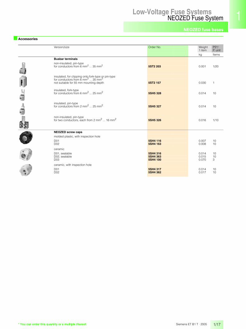
■ Accessories
MW Order No. Weight PS*/P. unit1 item
kg Items
NEOZED covers made of molded plastic
cover A1 (for sizes D01, D02), clip-on 1.5 5SH5 244 0.008 1/15
cover A2 (for sizes D01, D02), clip-on 4.5 5SH5 245 0.017 1/5
cover A4 (for size D01), clip-on 1.5 5SH5 251 0.012 1/15cover A10 (for size D02), clip-on 1.5 5SH5 253 0.020 1/15
cover A5 (for size D01), clip-on 4.5 5SH5 252 0.035 1/5cover A11 (for size D02), clip-on 4.5 5SH5 254 0.045 1/5
cover A6 (for size D03), screw-on 2.5 5SH5 233 0.021 1/20
NEOZED caps made of molded plastic
cover A8, clip-on – 5SH5 235 0.034 1/20cover A9, screw-on – 5SH5 234 0.066 1/10
* You can order this quantity or a multiple thereof.

NEOZED fuse bases
1/16
NEOZED Fuse SystemLow-Voltage Fuse Systems
Siemens ET B1 T · 2005
■ Accessories
1) For terminal version, see pages 1/12 and 1/13.
Size Length Conductor Load capacity up to
For MW Order No. Weight PS*/P. unitapprox. cross-
sectionTerminals 1) 1 item
mm mm2 A kg Items
Busbars
the load capacity values are valid for centered infeed.
fork-type terminals, non-insulated
1-pole
D01 1000 20 116 R, K 1.5 5SH5 321 0.214 1/50D02 1000 36 168 R, K 1.5 5SH5 322 0.321 1/50
fork-type terminals, insulated
1-pole
D01/D02 1000 24 160 R, FR2, K 1.5 5SH5 517 0.550 1/50
3-pole
D01/D02 1000 16 120 R, K 1.5 5SH5 320 0.843 1/20D01/D02 1000 16 120 FR2, K 1.5 5SH5 515 0.584 1/10
pins, insulated
degree of pollution 2
1-pole
D01/D02 1000 16 130 S 1.5 5SH5 324 0.320 1/50
3-pole
D01/D02 1000 16 120 S 1.5 5SH5 323 0.843 1/20
D01 1000 16 120 FR1 1 5SH5 512 0.630 1/15D01 216 16 120 FR2, K 1 5ST2 204 0.090 1/25
End caps for busbars
for 5SH5 320, 5SH5 323, 5SH5 512, 5ST2 204 5SH5 514 0.001 10
for 5SH5 515, 5SH5 517, 5SH5 324 5ST2 156 0.017 10
Busbar adapters
for clipping onto busbars12 mm × 5 mm, with 40 mm center clearance, device width 4.5 MW, with connection cables, 3 mm × 16 mm2 for rated current 63 A, for mounting of modular installation devices
busbar adapter for clipping onto busbars with 60 mm center clearance, see SR60 busbar system
5SH5 503 0.280 1
* You can order this quantity or a multiple thereof.
NEOZED fuse bases
1/17
NEOZED Fuse SystemLow-Voltage Fuse Systems 1
345678910
1213
Siemens ET B1 T · 2005
■ Accessories
Version/size Order No. Weight PS*/P. unit1 item
kg Items
Busbar terminals
non-insulated, pin-typefor conductors from 6 mm2 ... 35 mm2 5ST2 203 0.001 1/20
insulated, for clipping onto fork-type or pin-typefor conductors from 6 mm2 ... 35 mm2
not suitable for 55 mm mounting depth 5ST2 157 0.030 1
insulated, fork-typefor conductors from 6 mm2 ... 25 mm2 5SH5 328 0.014 10
insulated, pin-typefor conductors from 2 mm2 ... 25 mm2 5SH5 327 0.014 10
non-insulated, pin-typefor two conductors, each from 2 mm2 ... 16 mm2 5SH5 326 0.016 1/10
NEOZED screw caps
molded plastic, with inspection hole
D01 5SH4 116 0.007 10D02 5SH4 163 0.008 10
ceramic
D01, sealable 5SH4 316 0.014 10D02, sealable 5SH4 363 0.015 10D03 5SH4 100 0.070 3
ceramic, with inspection hole
D01 5SH4 317 0.014 10D02 5SH4 362 0.017 10
* You can order this quantity or a multiple thereof.

NEOZED fuse bases
1/18
NEOZED Fuse SystemLow-Voltage Fuse Systems
Siemens ET B1 T · 2005
■ Accessories
■ Dimensional drawings
with protection against contact BGV A2 (VBG4), molded plastic
Size For Identification color
Order No. Weight PS*/P. unitfuse 1 item
up to A kg Items
NEOZED adapter sleeves
D01 2 pink 5SH5 002 0.001 104 brown 5SH5 004 0.001 106 green 5SH5 006 0.001 10
10/13 red 5SH5 010 0.001 10
D02 20 blue 5SH5 020 0.001 1025 yellow 5SH5 025 0.001 1032/35/40 black 5SH5 035 0.001 10
50 white 5SH5 050 0.001 10
D03 80 silver 5SH5 080 0.001 10
for adaptation of NEOZED fuse links D01 from 2 A ... 16 A,for insertion in NEOZED bases D02
D02 2 pink 5SH5 402 0.001 104 brown 5SH5 404 0.001 106 green 5SH5 406 0.001 10
10/13 red 5SH5 410 0.001 1016 gray 5SH5 416 0.001 10
NEOZED adapter sleeve fitter 5SH5 100 0.016 1
NEOZED retaining springsfor adaptation of NEOZED screw caps D02 to fit NEOZED fuse links D01
D02 2 ... 16 5SH5 400 0.001 25
for application in the five new German Laender, for adaptation of DL screw caps to insert NEOZED fuse links D01 in DL bases.
DL 2 ... 16 5SH5 417 0.001 25
with anti-slip terminal D01/D025SG1 300, 5SG1 700, 5SG5 300, 5SG5 700
with cover5SG1 330, 5SG1 331, 5SG1 730, 5SG1 731, 5SG5 330, 5SG5 730
����
���
�� ��
�
��
��
�
�
��
�������
���
����
�
� � � � � � � �
� � �� � � �
� � � � � � � � � � � � � �
�
* You can order this quantity or a multiple thereof.
NEOZED fuse bases
1/19
NEOZED Fuse SystemLow-Voltage Fuse Systems 1
345678910
1213
Siemens ET B1 T · 2005
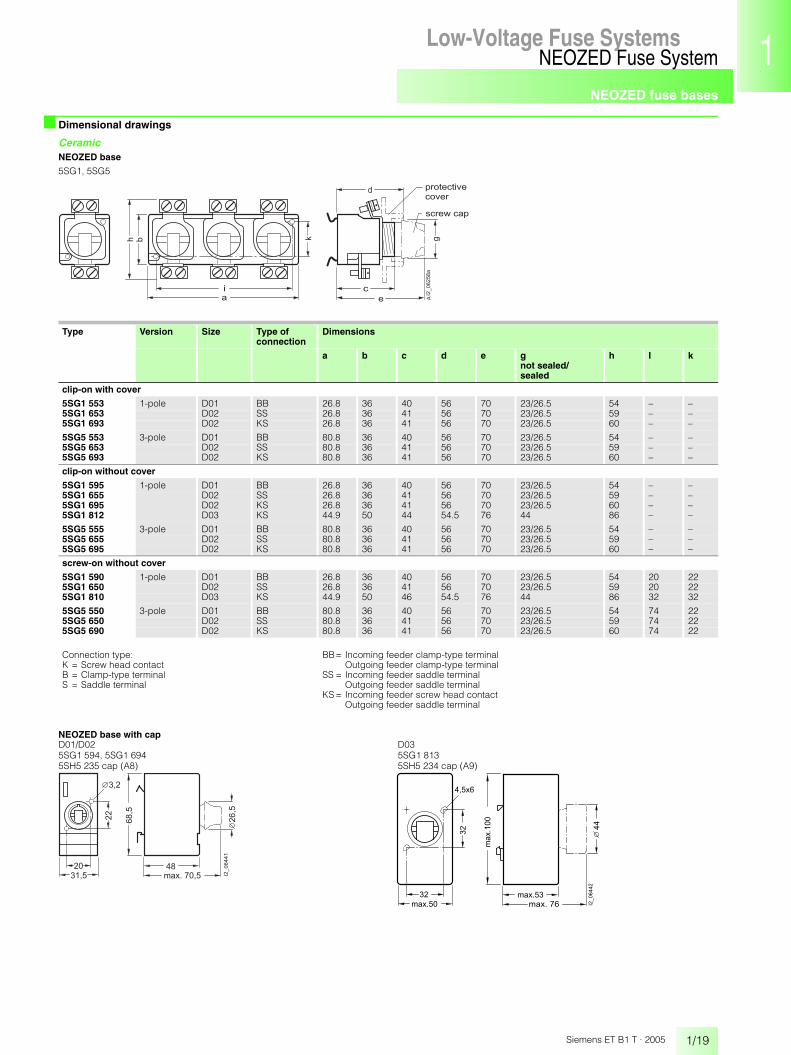
■ Dimensional drawings
CeramicNEOZED base
5SG1, 5SG5
� ! "
#
�
�
��
��������
�
� � � � � � � � � �� � � � �
� � � � $ � � � �
Type Version Size Type of connection
Dimensions
a b c d e gnot sealed/sealed
h I k
clip-on with cover
5SG1 553 1-pole D01 BB 26.8 36 40 56 70 23/26.5 54 – –5SG1 653 D02 SS 26.8 36 41 56 70 23/26.5 59 – –5SG1 693 D02 KS 26.8 36 41 56 70 23/26.5 60 – –
5SG5 553 3-pole D01 BB 80.8 36 40 56 70 23/26.5 54 – –5SG5 653 D02 SS 80.8 36 41 56 70 23/26.5 59 – –5SG5 693 D02 KS 80.8 36 41 56 70 23/26.5 60 – –
clip-on without cover
5SG1 595 1-pole D01 BB 26.8 36 40 56 70 23/26.5 54 – –5SG1 655 D02 SS 26.8 36 41 56 70 23/26.5 59 – –5SG1 695 D02 KS 26.8 36 41 56 70 23/26.5 60 – –5SG1 812 D03 KS 44.9 50 44 54.5 76 44 86 – –
5SG5 555 3-pole D01 BB 80.8 36 40 56 70 23/26.5 54 – –5SG5 655 D02 SS 80.8 36 41 56 70 23/26.5 59 – –5SG5 695 D02 KS 80.8 36 41 56 70 23/26.5 60 – –
screw-on without cover
5SG1 590 1-pole D01 BB 26.8 36 40 56 70 23/26.5 54 20 225SG1 650 D02 SS 26.8 36 41 56 70 23/26.5 59 20 225SG1 810 D03 KS 44.9 50 46 54.5 76 44 86 32 32
5SG5 550 3-pole D01 BB 80.8 36 40 56 70 23/26.5 54 74 225SG5 650 D02 SS 80.8 36 41 56 70 23/26.5 59 74 225SG5 690 D02 KS 80.8 36 41 56 70 23/26.5 60 74 22
Connection type:K = Screw head contactB = Clamp-type terminalS = Saddle terminal
BB= Incoming feeder clamp-type terminalOutgoing feeder clamp-type terminal
SS = Incoming feeder saddle terminalOutgoing feeder saddle terminal
KS = Incoming feeder screw head contactOutgoing feeder saddle terminal
NEOZED base with capD01/D02 D035SG1 594, 5SG1 694 5SG1 8135SH5 235 cap (A8) 5SH5 234 cap (A9)
��
��
��
��
���
��
��
����� �
����
�
� �������
��
��
� ����
�����
�
��
��
��
� ����� ��
���
��
� ����

NEOZED fuse bases
1/20
NEOZED Fuse SystemLow-Voltage Fuse Systems
Siemens ET B1 T · 2005
■ Dimensional drawings
NEOZED covers made of molded plastic
NEOZED screw caps
NEOZED cover for NEOZED base, made of molded plastic 5SH5 244 (A1) and 5SH5 245 (A2)
NEOZED cover5SH5 251 (A4) and 5SH5 253 (A10) 5SH5 252 (A5) and 5SH5 254 (A11) 5SH5 233 (A6)
��
���
��
�
��
��
���� ���� �
��
�� �
�
��
��
���
���
��
� ��
��
��
���
��
�
�
��
��
��
��
���
���
�
5SG4 Type Size Sealable for Dimensionsmounting depth
a b
5SH4 1165SH4 1635SH4 3165SH4 3635SH4 1005SH4 3175SH4 362
D01D02D01D02D03D01D02
––xx–––
55/7055/707070767070
24.524.533333729.530.5
232326.526.5442525
��������
�

NEOZED fuse disconnectors
1/21
NEOZED Fuse SystemLow-Voltage Fuse Systems 1
345678910
1213
Siemens ET B1 T · 2005
■ Benefits• With draw-out type for safe, no-voltage changing of fuse links• Rated voltage: 415 V AC/48 V DC
• No switching under load• With anti-slip terminal according to BGV A2 (VBG4) in the incoming
and outgoing cable
■ Technical specifications
Terminal designationsFR1 = anti-slip terminalAnti-slip terminals differ in the• Terminal level for the conductors• Terminal level for the busbars• Busbar version (fork-type or pin)• Modular sizeDifferent versions cannot be busbar mounted with each other. To facilitate assignment of the busbars, we have introduced the terminal marking FR1.
NEOZED fuse disconnectors5SG7 6
Valid standards DIN VDE 0638/09.81, EN 60947-3
Dimensions DIN 43880
Main switch characteristic EN 60204-1
Dielectric characteristic EN 60664-1
Rated voltage Un V 230/400 AC, 240/415 ACV 48 DC: 1-pole, 110 DC: 2-pole in series
Rated current In A 16
Rated insulation voltage V AC 400
Rated impulse withstand voltage V AC 2500
Rated breaking capacity kA 50 AC
Sealable when switched on yes
Mounting position vertical
Degree of protection according to IEC 60529 in distribution boards with section cover
IP20
Ambient temperature °C -5 ... +40, humidity 90 % at 20
Terminals Terminal FR1
Size D01
Conductor cross-sectionsminimum conductor cross-section of 1.5 mm2 must be observed, in accordance with VDE 0638
Rigid, minimum mm2 1.5Rigid, maximum mm2 16
Flexible with sleeve, min. mm2 1.5

NEOZED fuse disconnectors
1/22
NEOZED Fuse SystemLow-Voltage Fuse Systems
Siemens ET B1 T · 2005
■ Selection and ordering data
■ Dimensional drawings
D01, draw-out type
Number of poles
In Terminals MW Order No. Weight PS*/P. unit1 item
A kg Items
D01, draw-out type1 16 FR1 1 5SG7 610 0.070 1
1 + N 16 FR1 2 5SG7 650 0.150 1
2 16 FR1 2 5SG7 620 0.150 1
3 16 FR1 3 5SG7 630 0.220 1
3 + N 16 FR1 4 5SG7 660 0.300 1
�
�
�
�
�
�
�
�
�
�
�
�
�
�
�
�
�
�
�
5SG7 6.0
���
��
��
��
����
����
�
��
��� �� ��
* You can order this quantity or a multiple thereof.

MINIZED switch disconnectors
1/23
NEOZED Fuse SystemLow-Voltage Fuse Systems 1
345678910
1213
Siemens ET B1 T · 2005
■ Overview
MINIZED switch disconnector D01, draw-out type• 55 mm mounting depth• With protection against contact according to BGV A2 (VBG4)• Size D01• For mounting rail• Anti-slip terminal at ingoing and outgoing feeder• For busbar mounting• Knob-operated switch and screw cap can be sealed• With draw-out type for safe, no-voltage changing of fuse links• Special version for Italy for 25 A • Suitable for direct starting on load) MINIZED switch disconnector D01, draw-out type* NEOZED fuse link D010 Busbar, insulated, pins1 Terminal, not insulated or insulated, pins
MINIZED switch disconnector D02, draw-out type• 70 mm mounting depth• With protection against contact according to BGV A2 (VBG4)• Size D02• For mounting rail• Anti-slip terminal at ingoing and outgoing feeder• For busbar mounting• Knob-operated switch and screw cap can be sealed• With draw-out type for safe, no-voltage changing of fuse links• Suitable for direct starting on load) MINIZED switch disconnector D02, draw-out type* NEOZED fuse link D01+ NEOZED fuse link D02, NEOZED adapter sleeve- NEOZED adapter0 Busbar, insulated single-phase or 3-phase, fork-type1 Terminal, not insulated or insulated, fork-type
�������
��
�
�
��
��
�������
��
��
��
��
�
� �

MINIZED switch disconnectors
1/24
NEOZED Fuse SystemLow-Voltage Fuse Systems
Siemens ET B1 T · 2005
■ Benefits
FunctionMINIZED switch disconnectors belong to the NEOZED fuse range. They completely disconnect the phase in the incoming and outgoing cable by switching off. They are suited for NEOZED fuse links.A mechanical interlock prevents closing if NEOZED fuse links have not been correctly screwed in or plugged in.
Universal applicationThe MINIZED switch disconnectors D02 can accept both D02 and D01 fuse links. For inserting D01 fuse links, a retaining spring is used in the screw cap or an adapter is plugged into the drawer, depending on the version.
Busbar mountingFor the MINIZED switch disconnector D02, the incoming and outgoing terminals are identical and can be mounted on busbars. Infeed and/or busbar mounting is possible from the top or bottom.
■ Technical specifications
Terminal designationsFR1= anti-slip terminalFR2= anti-slip terminalAnti-slip terminals differ in the• Terminal level for the conductors• Terminal level for the busbars• Busbar version (fork-type or pin)• Modular sizeDifferent versions cannot be busbar mounted with each other. To facilitate assignment of the busbars, we have introduced the terminal markings FR1 and FR2.
MINIZED switch disconnectors5SG7 7 5SG7 1.2 5SG7 132-8BA..
Valid standards DIN VDE 0638/09.81, EN 60947-3
Dimensions DIN 43880
Main switch characteristic EN 60204-1
Dielectric characteristic EN 60664-1
Rated voltage Un V 230/400 AC, 240/415 ACV 48 DC 1-pole, 110 DC 2-pole in series
Rated current In A 16 63 25, 35, 50
Rated insulation voltage V AC 400
Rated impulse withstand voltage V AC 2500
Rated breaking capacity kA 50 AC
Switching capacity
Utilization category according to VDE 0638 AC-22 A 16 63AC-23 A 10 –DC -22 A 16 –
Utilization category acc. to EN 60947-3 AC-22A A – 63AC-23A A – 35DC-22A A – 63AC-22B A 16 –AC-23B A 10 –DC-22B A 16 –
No-voltage changing of fuse links yes
With terminals according to BGV A2 (VGB4) in the ingoing and outgoing feeder
yes
Tightening torque Nm 1.2
Sealable when switched on yes
Mounting position vertical
Mounting depth mm 55 70
Degree of protection according to IEC 60529 in distribution boards with section cover
IP20
Ambient temperature °C -5 ... +40, humidity 90 % at 20
Terminals Terminal FR1 FR2
Size D01 D02
Conductor cross-sectionsminimum conductor cross-section of 1.5 mm2 must be observed, in accordance with VDE 0638
Rigid, minimum mm2 1.5Rigid, maximum mm2 16
Flexible with sleeve, min. mm2 1.5
MINIZED switch disconnectors
1/25
NEOZED Fuse SystemLow-Voltage Fuse Systems 1
345678910
1213
Siemens ET B1 T · 2005
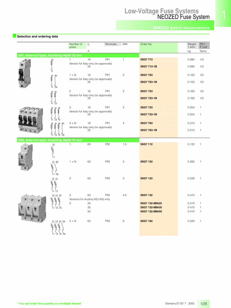
■ Selection and ordering data
Number of poles
In Terminals MW Order No. Weight PS*/P. unit1 item
A kg Items
D01, draw-out type, mounting depth 55 mm1 16 FR1 1 5SG7 713 0.080 1/3
Version for Italy only (no approvals)25 5SG7 713-1B 0.080 1/3
1 + N 16 FR1 2 5SG7 753 0.150 1/2
Version for Italy only (no approvals)25 5SG7 753-1B 0.150 1/2
2 16 FR1 2 5SG7 723 0.160 1/2
Version for Italy only (no approvals)25 5SG7 723-1B 0.160 1/2
3 16 FR1 3 5SG7 733 0.254 1
Version for Italy only (no approvals)25 5SG7 733-1B 0.254 1
3 + N 16 FR1 4 5SG7 763 0.310 1
Version for Italy only (no approvals)25 5SG7 763-1B 0.310 1
D02, draw-out type, mounting depth 70 mm1 63 FR2 1.5 5SG7 112 0.132 1
1 + N 63 FR2 3 5SG7 152 0.265 1
2 63 FR2 3 5SG7 122 0.226 1
3 63 FR2 4.5 5SG7 132 0.410 1
Versions for Austria (KELAG) only
3 25 5SG7 132-8BA25 0.410 1
35 5SG7 132-8BA35 0.410 1
50 5SG7 132-8BA50 0.410 1
3 + N 63 FR2 6 5SG7 162 0.520 1
2
1
1
N
N
2
1 3
2 4
2 4 6
1 3 5
2 4 6 N
1 3 5 N
�
�
�
�
�
�
�
�
�
�
�
�
�
�
�
�
�
�
�
* You can order this quantity or a multiple thereof.

MINIZED switch disconnectors
1/26
NEOZED Fuse SystemLow-Voltage Fuse Systems
Siemens ET B1 T · 2005
■ Accessories
■ Dimensional drawings
D01, draw-out type, mounting depth 55 mm
D02, draw-out type, mounting depth 70 mm
Size For Identification color
Order No. Weight PS*/P. unitfuse 1 item
up to A kg Items
D01, draw-out type, mounting depth 55 mmTerminalnot insulated, up to 25 mm2
5SH5 510 0.012 1/50
D02, draw-out type, mounting depth 70 mmAuxiliary switchfor contact position indication, for retrofitting on the right side using the factory-fitted brackets, 0.5 MW
5SH5 528 0.050 1
Contact: 230 V AC, 6 A24 V AC, 50 mA24 V DC, 50 mA
1 NO + 1 NC
Adapter sleeve
D02 20 blue 5SH5 521 0.001 1025 yellow 5SH5 522 0.001 1035/40 black 5SH5 523 0.001 10
50 white 5SH5 524 0.001 10
NEOZED adapterfor insertion of NEOZED fuse links D01 in MINIZED switch disconnectors D02
D01 2 ... 6 green 5SH5 530 0.002 310 red 5SH5 531 0.002 316 gray 5SH5 520 0.002 3
5SG7 7.3 5SH5 528auxiliary switch
�����
��
��
��
�
��
��
�
�
�
�
�
�
�
�
�
�
�
�
�
�
�
�
�
�
�
� �� �� �� ��
��
��
�
��
�� �
���
���
5SG7 1.2, 5SG7 132-8BA..
���
��
��
��
��
������
�����
��
��
��
���� ���� ��������
�
�
�
�
��
�
�
�
�
�
�
�
�
�
�
�
�
�
* You can order this quantity or a multiple thereof.

Product overview
1/27
DIAZED Fuse SystemLow-Voltage Fuse Systems 1
345678910
1213
Siemens ET B1 T · 2005
■ Overview
DIAZED fuse links
DIAZED fuse links SILIZED (utilization category gR)
DIAZED fuse bases and accessories
Low-Voltage Fuse Systems

Product overview
1/28
DIAZED Fuse SystemLow-Voltage Fuse Systems
Siemens ET B1 T · 2005
■ Overview
The DIAZED component systemAs a result of the well-designed modular system, the components can be combined in any way to meet the various requirements and to facilitate different installation methods. It is particularly suitable for tough operating conditions.As modular installation devices, the bases are mounted in distribu-tion boards according to DIN 43880 or in switchgear cabinets on a standard mounting rail according to EN 50021. However, bases exclusively designed for screw connection are also available.A special busbar with oblong holes and a load capacity of up to 80 A facilitates adaptation during mounting.
The EZR bus-mounting systemThe high-performing EZR bus-mounting system for screw connec-tion is an outstanding feature.The busbars, which are particularly suited for bus-mounting bases, have a load capacity of up to 150 A with lateral infeed.
������
�
�
��
��
�
��
��
�
�
�
�
��
��
�
��
$%&()*+,-./01234
DIAZED baseDIAZED coverDIAZED cover ringDIAZED capDIAZED bus-mounting base, EZRDIAZED bus-mounting base, EZR, 3-phaseDIAZED cover ring, EZR for bus-mounting baseDIAZED fuse link DIIDIAZED fuse link NDzDIAZED screw adapterDIAZED adapter sleeveDIAZED screw capBusbar, oblong hole, single-phaseTerminal, fork-type terminal, non-insulatedEZR busbarEZR terminal

DIAZED fuse links
1/29
DIAZED Fuse SystemLow-Voltage Fuse Systems 1
345678910
1213
Siemens ET B1 T · 2005
■ Overview
Correct infeedAll DIAZED bases must be fed from the bottom to ensure an insulated threaded ring when the fuse link is being removed.
Contact stabilityDIAZED screw adapters are essential in the DIAZED base for stable contacting.
Types of connectionB = clamp-type terminalK = screw head contactS = saddle terminal
Designation systemThe conventional designation signifies the following, e.g. "BS" = :1st letter: clamp-type terminal, incoming feeder, bottom terminal2nd letter: saddle terminal, outgoing feeder, top terminal
DIAZED 5SF6 005 bus-mounting base DII for 25 A with terminal version "B" mounted onto an EZR 5SH3 54 busbar. The feeding conductors are clamped to the 8JH4 122 bus-mounting terminal. The busbar has a load capacity of up to 150 A.
DIAZED bus-mounting base DII 3-phase for 3 x 25 A, 5SF2 07 with terminal version "B" mounted onto 3 EZR 5SH3 54 busbars. The busbars have a load capacity of 150 A each respectively.
■ Technical specifications
S
B
B
B
K
K
DIAZED fuse linksStandards DIN VDE 0635, DIN VDE 0636-301, DIN VDE 0680,
IEC 60269-1, -3-1, CEE 16, EN 60269-1, -3-1
Dimensions DIN 49510, DIN 49511, DIN 49514, DIN 49515, DIN 49516
Utilization category gL/gG
Characteristic slow and quick
Rated voltage Un V AC 500, 690, 750V DC 500, 600, 750
Rated current In A 2 ... 100
Rated breaking capacity kA AC 50, 40 at E16kA DC 8, 1.6 at E16
Mounting position any, but preferably vertical
Non-interchangeability due to screw adapter or adapter sleeves
Degree of protection according to IEC 60529 in the distribution board
IP20
Resistance to climate °C up to 45 at 95 % rel. humidity
Ambient temperature °C -5 ... +40, humidity 90 % at 20
DIAZED fuse links
1/30
DIAZED Fuse SystemLow-Voltage Fuse Systems
Siemens ET B1 T · 2005
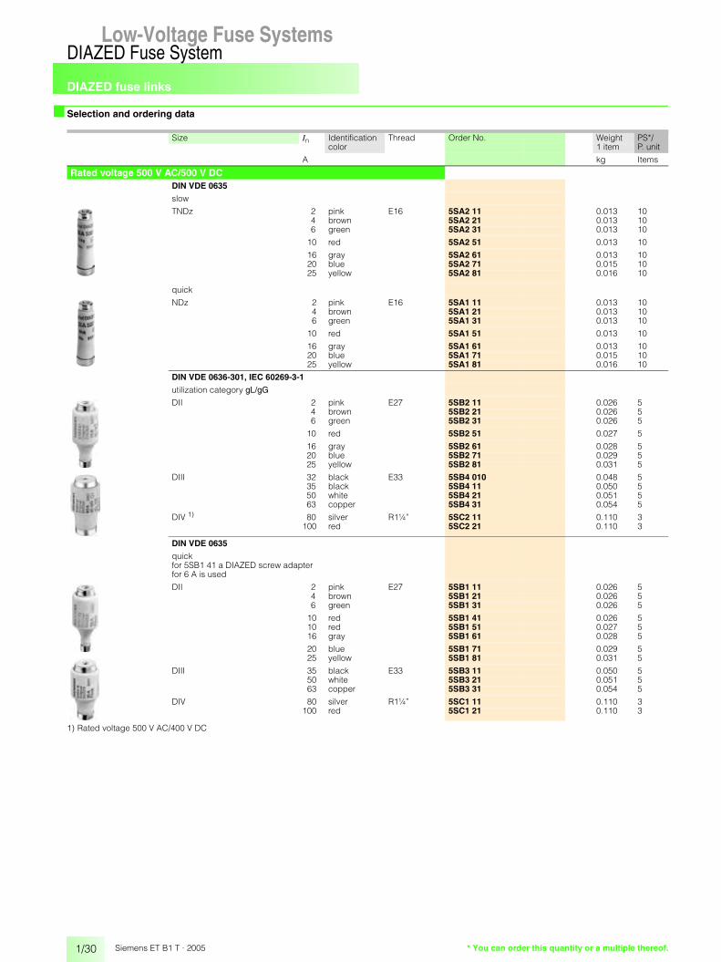
■ Selection and ordering data
1) Rated voltage 500 V AC/400 V DC
Size In Identification color
Thread Order No. Weight PS*/P. unit1 item
A kg Items
Rated voltage 500 V AC/500 V DCDIN VDE 0635
slow
TNDz 2 pink E16 5SA2 11 0.013 104 brown 5SA2 21 0.013 106 green 5SA2 31 0.013 10
10 red 5SA2 51 0.013 10
16 gray 5SA2 61 0.013 1020 blue 5SA2 71 0.015 1025 yellow 5SA2 81 0.016 10
quick
NDz 2 pink E16 5SA1 11 0.013 104 brown 5SA1 21 0.013 106 green 5SA1 31 0.013 10
10 red 5SA1 51 0.013 10
16 gray 5SA1 61 0.013 1020 blue 5SA1 71 0.015 1025 yellow 5SA1 81 0.016 10
DIN VDE 0636-301, IEC 60269-3-1
utilization category gL/gG
DII 2 pink E27 5SB2 11 0.026 54 brown 5SB2 21 0.026 56 green 5SB2 31 0.026 5
10 red 5SB2 51 0.027 5
16 gray 5SB2 61 0.028 520 blue 5SB2 71 0.029 525 yellow 5SB2 81 0.031 5
DIII 32 black E33 5SB4 010 0.048 535 black 5SB4 11 0.050 550 white 5SB4 21 0.051 563 copper 5SB4 31 0.054 5
DIV 1) 80 silver R1¼” 5SC2 11 0.110 3100 red 5SC2 21 0.110 3
DIN VDE 0635
quickfor 5SB1 41 a DIAZED screw adapter for 6 A is used
DII 2 pink E27 5SB1 11 0.026 54 brown 5SB1 21 0.026 56 green 5SB1 31 0.026 5
10 red 5SB1 41 0.026 510 red 5SB1 51 0.027 516 gray 5SB1 61 0.028 5
20 blue 5SB1 71 0.029 525 yellow 5SB1 81 0.031 5
DIII 35 black E33 5SB3 11 0.050 550 white 5SB3 21 0.051 563 copper 5SB3 31 0.054 5
DIV 80 silver R1¼” 5SC1 11 0.110 3100 red 5SC1 21 0.110 3
* You can order this quantity or a multiple thereof.

DIAZED fuse links
1/31
DIAZED Fuse SystemLow-Voltage Fuse Systems 1
345678910
1213
Siemens ET B1 T · 2005
■ Selection and ordering data
Size In Identification color
Thread Order No. Weight PS*/P. unit1 item
A kg Items
Rated voltage 690 V AC/600 V DCDIN VDE 0636-301, IEC 60269-3-1
utilization category gL/gG,DIAZED screw adapters DII are used for fuse links 2 A ... 25 A
DIII 2 pink E33 5SD8 002 0.068 54 brown 5SD8 004 0.068 56 green 5SD8 006 0.068 5
10 red 5SD8 010 0.068 516 gray 5SD8 016 0.069 5
20 blue 5SD8 020 0.071 525 yellow 5SD8 025 0.072 5
35 black 5SD8 035 0.078 550 white 5SD8 050 0.080 563 copper 5SD8 063 0.082 5
Rated voltage 750 V AC/750 V DCDIN VDE 0635
for direct current railway facilities,quickDIAZED screw adapters DII are used for fuse links 2 A ... 25 A
DIII 2 pink E33 5SD6 01 0.068 54 brown 5SD6 02 0.068 56 green 5SD6 03 0.068 5
10 red 5SD6 04 0.068 516 gray 5SD6 05 0.069 5
20 blue 5SD6 06 0.071 525 yellow 5SD6 07 0.072 535 black 5SD6 08 0.078 550 white 5SD6 10 0.080 5
63 copper 5SD6 11 0.082 5
* You can order this quantity or a multiple thereof.

DIAZED fuse links
1/32
DIAZED Fuse SystemLow-Voltage Fuse Systems
Siemens ET B1 T · 2005
■ Characteristic curves
Series 5SA2Size: E16Characteristic: slowRated voltage: 500 V AC/500 V DCRated current: 2 ... 25 ATime/current characteristics diagram
Current limitation diagram
$ Peak short-circuit current with largest DC component
% Peak short-circuit current without DC component
Melting I2ts values diagram
�� � �
� � � �
�
�
�
� � � �
�� � � �� � �� � � �� � �
�
�
�
� � � �
�
�
�
� � �
�
�
�
� � �
�
�
�
� � �
�
�
�
� � �
�
�
�
� � �
�������
� � � ��
� � �
�
� � � � � �
���
� � � � � � � � � � � � � �
� � � � � � �
� � � � �� � � ��
�
�
�
�
�
�
� �
�������
�
� � �
�
� � � � � �
���
� � �
�
� � �
�
�
�
� � �
� �� � � �� � �� � � �� � �
� � �
� � �
� � � �
� � � �
� � � �
� � �
� �
Type In Pv �� I2ts1 ms 4 ms
A W k A2s A2s
5SA2 11 2 0.85 15 1.2 2.35SA2 21 4 1.3 17 8.5 135SA2 31 6 1.9 14 40 80
5SA2 51 10 1.4 17 200 1905SA2 61 16 2.4 30 290 5505SA2 71 20 2.6 36 470 1990
5SA2 81 25 3.4 34 1000 2090
Type I2ta230 V AC 320 V AC 500 V AC
A2s A2s A2s
5SA2 11 6.6 7.8 0.75SA2 21 22 26 345SA2 31 66 76 100
5SA2 51 240 270 3405SA2 61 890 950 10905SA2 71 1200 1350 1620
5SA2 81 2400 2600 3450
� � � �� � �� � �� � � �� � �� � � �� �� � � � �� ��� �
�
�
�
� �
�
�
�
� �
�
�
�
� �
�
�
�
� �
�
�
�
� �
�
�
�
� �
�������
�
�
�
�
�
�
�
� � �
� � � �
� � � �
� � �
� � � � � �
��
�����
�
� � � � � � � � � � � � � � � � � � � � � � � �
� � �
� � �
� � � �

DIAZED fuse links
1/33
DIAZED Fuse SystemLow-Voltage Fuse Systems 1
345678910
1213
Siemens ET B1 T · 2005
■ Characteristic curves
Series 5SA1Size: E16Characteristic: quickRated voltage: 500 V AC/500 V DCRated current: 2 ... 25 ATime/current characteristics diagram
Current limitation diagram
$ Peak short-circuit current with largest DC component
% Peak short-circuit current without DC component
Melting I2ts values diagram
�� � �
� � � �
�
�
�
� � � �
�� � � �� � �� � � �� � �
�
�
�
� � � �
�
�
�
� � �
�
�
�
� � �
�
�
�
� � �
�
�
�
� � �
�
�
�
� � �
�������
� � � ��
�
� � � � � �
���
� � � � � � � � � � � � �
� � � �
� � �
� � � �
� � � � �� � ��
� � � � � �
� � �� � �� � � �� � �� �
������
� � �
� � � �
� � �
�
�
�
� �
�
�
�
�
�
����
� �
�
� � �
�
��
� �
� � �
� � � �
� � � �
� � �
Type In Pv
A W
5SA1 11 2 1.55SA1 21 4 1.95SA1 31 6 2.7
5SA1 51 10 3.45SA1 61 16 3.75SA1 71 20 4.4
5SA1 81 25 4.9
� � � �� � �� � �� � � �� � �� � � �� �� � � � �� ��� �
�
�
�
� �
�
�
�
� �
�
�
�
� �
�
�
�
� �
�
�
�
� �
�
�
�
� �
�������
�
�
�
�
�
�
�
� � �
� � � � � �
��
�����
�
� � � �
� � �
� � �
� � � �
� � � �
� � �
� � � �
� � � � �
� � � � �
� � � � �
� � � � �

DIAZED fuse links
1/34
DIAZED Fuse SystemLow-Voltage Fuse Systems
Siemens ET B1 T · 2005
■ Characteristic curves
Series 5SB2, 5SB4, 5SC2Size: DII, DIII, DIVUtilization category: gL/gGRated voltage: 500 V AC/500 V DCRated current: 2 ... 100 ATime/current characteristics diagram
Current limitation diagram
$ Peak short-circuit current with largest DC component
% Peak short-circuit current without DC component
Melting I2ts values diagram
�� � �
� � � �
�
�
�
� � � �
�� � � �� � �� � � �� � �
�
�
�
� � � �
�
�
�
� � �
�
�
�
� � �
�
�
�
� � �
�
�
�
� � �
�
�
�
� � �
� � � ��
�
� � � � � �
���
�
�������
���
���
���
����
����
����
���
����
���
���
����
���
�����
� � � � �� � � ��
�
�
�
�
�
�
� �
�������
�
� � �
�
� � � � � �
���
� � �
�
� � �
�
�
�
� � �
� �� � � �� � �� � � �� � �
� � �
� � �
� � � �
� � � �
� � � �
� � �
� � � �
� � �
� � � �
� � �
� � � � �
� �
� � �
Type In Pv �� I2ts1 ms 4 ms
A W k A2s A2s
5SB2 11 2 2.6 15 3.7 3.9 5SB2 21 4 2.0 13 15 16 5SB2 31 6 2.2 14 42 45
5SB2 51 10 1.6 20 120 140 5SB2 61 16 2.4 23 500 580 5SB2 71 20 2.6 26 750 1100
5SB2 81 25 3.4 38 1600 2000 5SB4 010 32 3.6 23 2300 2500 5SB4 11 35 3.7 25 3450 3000 5SB4 21 50 5.7 41 6500 5200
5SB4 31 63 6.9 48 11000 12000 5SC2 11 80 7.5 33 14600 16400 5SC2 21 100 8.8 46 28600 30000
Type I2ta230 V AC 320 V AC 500 V AC
A2s A2s A2s
5SB2 11 6.6 8.8 10.7 5SB2 21 22 28 34 5SB2 31 66 85 100
5SB2 51 240 300 340 5SB2 61 890 1060 1090 5SB2 71 1200 1450 1620
5SB2 81 2400 3150 3450 5SB4 010 3450 4150 4850 5SB4 11 5200 6200 7200 5SB4 21 9750 12350 14500
5SB4 31 16500 22200 26500 5SC2 11 23000 28500 32500 5SC2 21 44000 56000 65000
� � � �� � �� � �� � � �� � �� � � �� �� � � � �� ��� �
�
�
�
� �
�
�
�
� �
�
�
�
� �
�
�
�
� �
�
�
�
� �
�
�
�
� �
�������
�
�
�
�
�
�
�
� � �
� � � �
� � � �
� � �
� � � � � �
��
�����
�
� � �
� � �
� � � �
� � � � �
� � �
� � � �
� � �
� � �
� ���
� �� �� � �
� �� � �
� �� � �
� ��
� � � �

DIAZED fuse links
1/35
DIAZED Fuse SystemLow-Voltage Fuse Systems 1
345678910
1213
Siemens ET B1 T · 2005
■ Characteristic curves
Series 5SB1, 5SB3, 5SC1Size: DII, DIII, DIVUtilization category: quickRated voltage: 500 V AC/500 V DCRated current: 2 ... 100 ATime/current characteristics diagram
Current limitation diagram
$ Peak short-circuit current with largest DC component
% Peak short-circuit current without DC component
Melting I2ts values diagram
�� � �
� � � �
�
�
�
� � � �
�� � � �� � �� � � �� � �
�
�
�
� � � �
�
�
�
� � �
�
�
�
� � �
�
�
�
� � �
�
�
�
� � �
�
�
�
� � �
� � � ��
�
� � � � � �
���
�
�������
���
���
���
����
����
����
���
���
���
����
���
�����
� � � � �� � ��
� � � � � �
� � �� � �� � � �� � �� �
������
� � � �
� � �
�
�
�
� �
�
�
�
�
����
� �
�
� � �
�
��
� � � �
� � � �
� � �
�
� �
� � �
� � �
� � � � �
� � �
� � � �
� � �
� � �
Type In Pv �� I2ts I2ta4 ms 500 V AC
A W k A2s A2s
5SB1 11 2 1.5 3 2.5 55SB1 21 4 1.9 13 15.6 31.25SB1 31 6 2.7 18 36 72
5SB1 41, 5SB1 51 10 3.4 23 102 2045SB1 61 16 3.7 24 130 2605SB1 71 20 4.4 31 185 370
5SB1 81 25 4.9 34 250 5005SB3 11 35 8.3 39 640 12805SB3 21 50 9.9 49 1960 3920
5SB3 31 63 12.8 63 3880 77605SC1 11 80 12.7 45 10890 217805SC1 21 100 15.4 55 17400 34800
� � � �� � �� � �� � � �� � �� � � �� �� � � � �� ��� �
�
�
�
� �
�
�
�
� �
�
�
�
� �
�
�
�
� �
�
�
�
� �
�
�
�
� �
�������
�
�
�
�
�
�
�
� � � � � �
��
�����
�
� � � �
� � � �
� � �
� � �
� � �
� � � �
� � �
� � �
� � �
� � �
� � � � �
� � � �
� ���
� �� �� � �
� �� � �
� �� � �
� ��
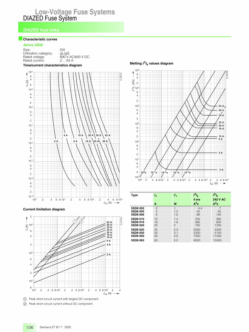
DIAZED fuse links
1/36
DIAZED Fuse SystemLow-Voltage Fuse Systems
Siemens ET B1 T · 2005
■ Characteristic curves
Series 5SD8Size: DIIIUtilization category: gL/gGRated voltage: 690 V AC/600 V DCRated current: 2 ... 63 ATime/current characteristics diagram
Current limitation diagram
$ Peak short-circuit current with largest DC component
% Peak short-circuit current without DC component
Melting I2ts values diagram
�� � �
� � � �
�
�
�
� � � �
�� � � �� � �� � � �� � �
�
�
�
� � � �
�
�
�
� � �
�
�
�
� � �
�
�
�
� � �
�
�
�
� � �
�
�
�
� � �
�������
� � � ��
�
� � � � � �
���
� � � � � � � � � � � � � � � � � � �
� � � � � � � � � � � � � � � �
� � � � �� � � ��
�
�
�
�������
� � �
�
� � � � � �
���
� �
� �� � � �� � �� � � �� � �
� � �
� � �
� � � �
� � � �
� � � �
� � �
�
� � �
�
�
�
� � �
�
�
� � � �
� � �
� � �
� �
Type In Pv I2ts I2ta4 ms 242 V AC
A W A2s A2s
5SD8 002 2 1 4.4 75SD8 004 4 1.2 40 625SD8 006 6 1.6 88 140
5SD8 010 10 1.4 240 3805SD8 016 16 1.8 380 6005SD8 020 20 2 750 1200
5SD8 025 25 2.3 2000 32005SD8 035 35 3.1 3300 51005SD8 050 50 4.6 7000 11000
5SD8 063 63 5.5 9500 15000
� � � �� � �� � �� � � �� � �� � � �� �� � � � �� ��� �
�
�
�
� �
�
�
�
� �
�
�
�
� �
�
�
�
� �
�
�
�
� �
�
�
�
� �
�������
�
�
�
�
�
�
�
� � �
� � � � � �
��
�����
�
� � � � � � � � � � � � � � � � � � � � � � � �
� � �
� � � �
� � � �
� � �
� � �
� � � �
� � �
� � �
� � � �

DIAZED fuse links
1/37
DIAZED Fuse SystemLow-Voltage Fuse Systems 1
345678910
1213
Siemens ET B1 T · 2005
■ Characteristic curves
Series 5SD6Size: DIIIUtilization category: quick (railway network protection)Rated voltage: 750 V AC/750 V DCRated current: 2 ... 63 ATime/current characteristics diagram
Current limitation diagram
$ Peak short-circuit current with largest DC component
% Peak short-circuit current without DC component
Melting I2ts values diagram
�� � �
� � � �
�
�
�
� � � �
�� � � �� � �� � � �� � �
�
�
�
� � � �
�
�
�
� � �
�
�
�
� � �
�
�
�
� � �
�
�
�
� � �
�
�
�
� � �
�������
� � � ��
�
� � � � � �
���
� � � � � � � � �� � �� � � �
� � � � � � � � � � � � � � � � � � �
� � � � �� � � ��
�
�
�������
� � �
�
� � � � � �
���
� �� �� � � �� � �� � � �� � �
� � �
� � �
� � � �
� � � �
� � � � �
�
� � �
�
�
�
� � �
�
� � � �
� � �
� � �
� �
Type In Pv I2ts I2ta4 ms 500 V AC
A W A2s A2s
5SD6 01 2 2.8 0.7 25SD6 02 4 4 4.5 135SD6 03 6 4.8 10 29
5SD6 04 10 4.8 50 1355SD6 05 16 5.9 78 2205SD6 06 20 6.3 125 380
5SD6 07 25 8.3 265 8005SD6 08 35 13 550 16005SD6 10 50 16.5 1800 5500
5SD6 11 63 18 3100 9600
� � � �� � �� � �� � � �� � �� � � �� �� � � � �� ��� �
�
�
�
� �
�
�
�
� �
�
�
�
� �
�
�
�
� �
�
�
�
� �
�
�
�
� �
�������
� �
�
�
�
�
�
�
� � � � � �
��
�����
�
� � �
� � �
� � �
� � � �
� � � �
� � � �
� � �
� � �
� � �
� � � �
� �� �� � �
� �� � �
� �� � �
� ��
� ���
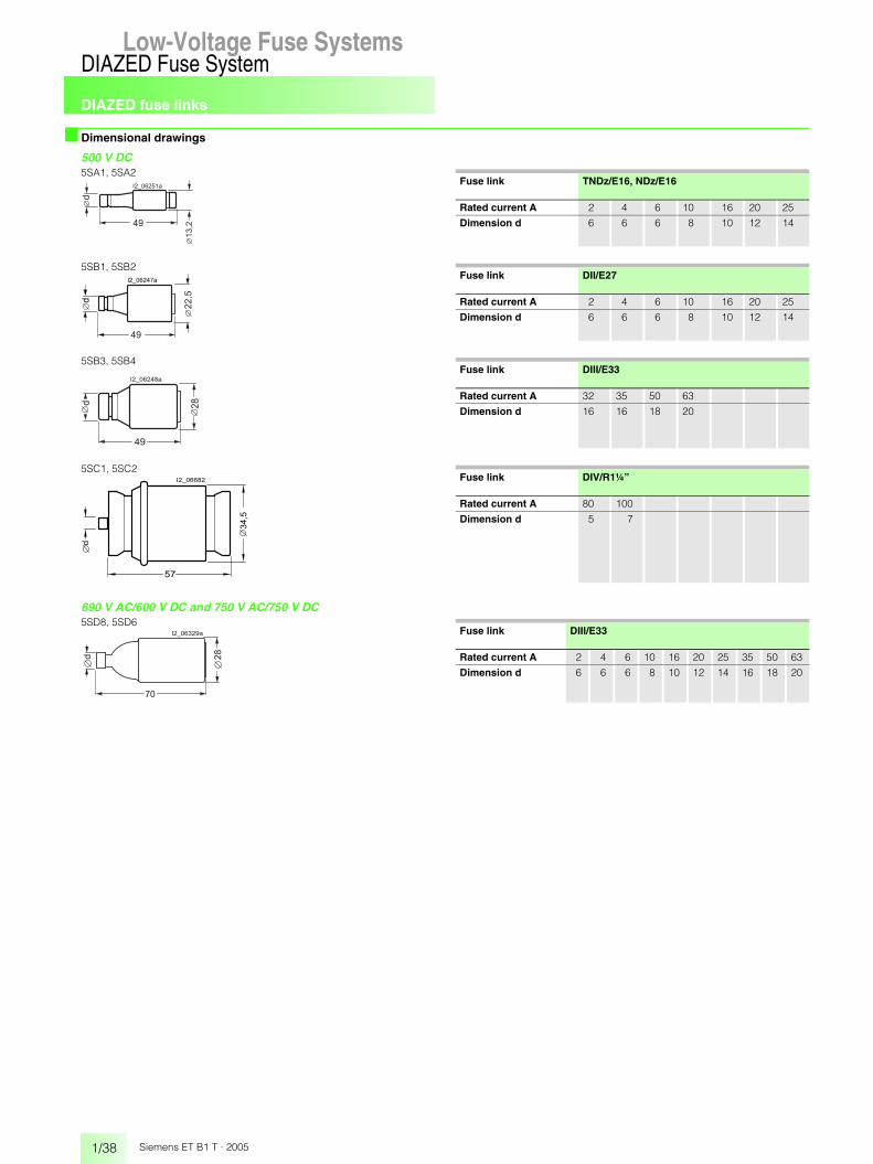
DIAZED fuse links
1/38
DIAZED Fuse SystemLow-Voltage Fuse Systems
Siemens ET B1 T · 2005
■ Dimensional drawings
500 V DC
690 V AC/600 V DC and 750 V AC/750 V DC
5SA1, 5SA2Fuse link TNDz/E16, NDz/E16
Rated current A 2 4 6 10 16 20 25
Dimension d 6 6 6 8 10 12 14��
�������
���
5SB1, 5SB2Fuse link DII/E27
Rated current A 2 4 6 10 16 20 25
Dimension d 6 6 6 8 10 12 14
��������
��
��
��
5SB3, 5SB4Fuse link DIII/E33
Rated current A 32 35 50 63
Dimension d 16 16 18 20
��
��������
��
5SC1, 5SC2Fuse link DIV/R1¼”
Rated current A 80 100
Dimension d 5 7
��
��
��
��������
5SD8, 5SD6Fuse link DIII/E33
Rated current A 2 4 6 10 16 20 25 35 50 63
Dimension d 6 6 6 8 10 12 14 16 18 20
��
��������
��
� �

DIAZED fuse links SILIZED(utilization category gR)
1/39
DIAZED Fuse SystemLow-Voltage Fuse Systems 1
345678910
1213
Siemens ET B1 T · 2005
■ Technical specifications
■ Selection and ordering data
Standards DIN VDE 0635, DIN VDE 0636-301, DIN VDE 0680, IEC 60269-3-1, CEE 16, EN 60269-3-1
Dimensions DIN VDE 49510, DIN VDE 49511, DIN VDE 49514, DIN VDE 49515, DIN VDE 49516
Utilization category gR
Characteristic high-speed
Rated voltage Un V AC 500
V DC 500
Rated current In A 16 ... 100
Rated breaking capacity kA AC 50, 40
kA DC 8, 1.6
Mounting position any, but preferably vertical
Non-interchangeability due to screw adapter or adapter sleeves
Degree of protection according to IEC 60529in the distribution board
IP20
Resistance to climate °C up to 45 at 95 % rel. humidity
Ambient temperature °C -5 ... +40, humidity 90 % at 20
Size In Identification color
Thread Order No. Weight PS*/P. unit1 item
A kg Items
Rated voltage 500 V AC/500 V DC DIN VDE 0636-301
for semiconductor protection, designation, yellow ringutilization category gR, super-quick.For 30 A fuse links the DIAZED screw adapter DII for 25 A is used
DII 16 gray E27 5SD4 20 0.028 520 blue 5SD4 30 0.029 525 yellow 5SD4 40 0.031 5
30 5SD4 80 0.031 5
DIII 35 black E33 5SD4 50 0.050 550 white 5SD4 60 0.051 563 copper 5SD4 70 0.054 5
DIV 80 silver R1¼” 5SD5 10 0.110 3100 red 5SD5 20 0.110 3
* You can order this quantity or a multiple thereof.
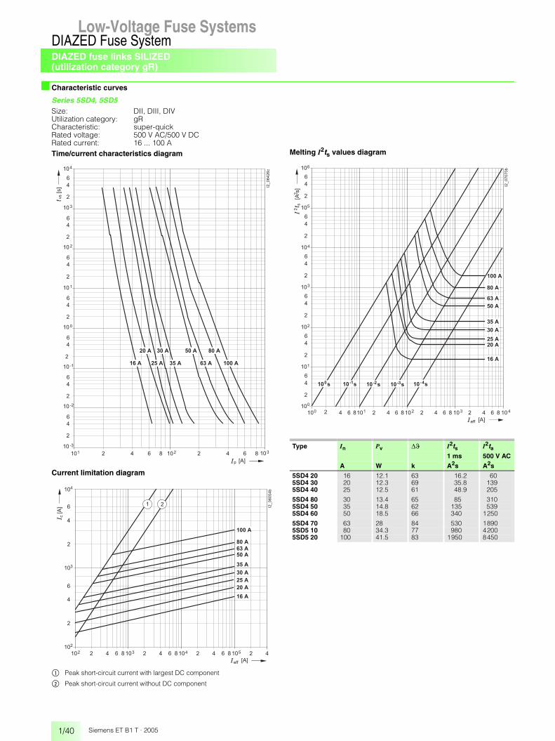
DIAZED fuse links SILIZED(utilization category gR)
1/40
DIAZED Fuse SystemLow-Voltage Fuse Systems
Siemens ET B1 T · 2005
■ Characteristic curves
Series 5SD4, 5SD5Size: DII, DIII, DIVUtilization category: gRCharacteristic: super-quickRated voltage: 500 V AC/500 V DCRated current: 16 ... 100 ATime/current characteristics diagram
Current limitation diagram
$ Peak short-circuit current with largest DC component
% Peak short-circuit current without DC component
Melting I2ts values diagram
�� � �
� � � �
�
�
�
� � � �
�� � � �� � �� � � ��
�
�
�
� � � �
�
�
�
� � �
�
�
�
� � �
�
�
�
� � �
�
�
�
� � �
�
�
�
� � �
�������
�
� � � �
� �
� � �� � � �� � � �
� � �� � �� � � � � � � �
� � �
� � � � �
� � � � �� � � ��
�
�
�������
�
� � � � � �
���
� �� �� � � �� � �� � � �� � �
� � � �
� � � �
�
� � �
�
�
�
� � �
� � �
� � �
� � � �
� � �
� � �
� � � �
� � �
� � � � �
Type In Pv �� I2ts I2ta1 ms 500 V AC
A W k A2s A2s
5SD4 20 16 12.1 63 16.2 605SD4 30 20 12.3 69 35.8 1395SD4 40 25 12.5 61 48.9 205
5SD4 80 30 13.4 65 85 3105SD4 50 35 14.8 62 135 5395SD4 60 50 18.5 66 340 1250
5SD4 70 63 28 84 530 18905SD5 10 80 34.3 77 980 42005SD5 20 100 41.5 83 1950 8450
� � � �� � �� � �� � � �� � �� � � �� ��� �
�
�
�
� �
�
�
�
� �
�
�
�
� �
�
�
�
� �
�
�
�
� �
�
�
�
� �
�������
�
�
�
�
�
�
� � � � � �
�
��� �
�
� � � �� ��
�
� �� �� � �
� �� � �
� ��� �
��
� � � �
� � � �
� � �
� � � �
� � �
� � � �
� � �
� � � � �
� � �
� �� ��

DIAZED fuse links SILIZED(utilization category gR)
1/41
DIAZED Fuse SystemLow-Voltage Fuse Systems 1
345678910
1213
Siemens ET B1 T · 2005
■ Dimensional drawings
500 V AC/500 V DC5SD4 20, 5SD4 30, 5SD4 40, 5SD4 80
Fuse link DII/E27
Rated current A 16 20 25 30
Dimension d 10 12 14 14
���������
�
����
5SD4 50, 5SD4 60, 5SD4 70Fuse link DIII/E33
Rated current A 35 50 63
Dimension d 16 18 20
�
������� �
�
5SD5 10, 5SD5 20Fuse link DIV/R1¼”
Rated current A 80 100
Dimension d 5 7
����
��
������ �

DIAZED fuse bases
1/42
DIAZED Fuse SystemLow-Voltage Fuse Systems
Siemens ET B1 T · 2005
■ Technical specifications
Terminal designationsB = clamp-type terminalK = screw head contactS = saddle terminalR = anti-slip terminal
■ Selection and ordering data
1) For terminal markings, see above and page 1/29.
TerminalsTerminal B K S R
Size DII DIII NDz DII DIII DIII DIV DII DIII
Conductor cross-sections
• Rigid, minimum mm2 1.5 2.5 1.0 1.5 2.5 2.5 10 1.5 1.5• Rigid, maximum mm2 10 25 6 10 25 25 50 35 35• Flexible with sleeve, max. mm2 10 25 6 10 25 25 50 35 35
Tightening torque
• Screw M4 Nm 1.2 –• Screw M5 Nm 2.0 –• Screw M6 Nm 2.5 4• Screw M8 Nm 3.5 –
Size In Thread Terminals 1) Order No. Weight PS*/P. unit1 item
A kg Items
DIAZED base made of ceramicrated voltage 500 V AC/500 V DC(for 690 VAC/600 V DC, size DIII bases are to be used together with DIAZED 5SH1 170 screw caps and DIAZED 5SD8 fuse links)
1-pole
NDz 25 E16 KK 5SF1 012 0.060 1/20
DII 25 E27 BB 5SF1 005 0.093 1/15
DIII 63 E33 BS 5SF1 205 0.191 1/15
DIII 63 E33 SS 5SF1 215 0.154 1/15
for screw connection only
NDz 25 E16 KK 5SF1 01 0.055 1/20
DII 25 E27 BB 5SF1 024 0.093 1/15
DIII 63 E33 BS 5SF1 224 0.137 1/15
DIII 63 E33 SS 5SF1 214 0.141 1/15
DIV 100 R1¼” flattermination
5SF1 401 0.380 1
rated voltage 750 V AC/750 V DConly for DIAZED 5SH1 161 screw caps,only for DIAZED screw adapters DII and DIII,only for DIAZED 5SD6 fuse linkswith fine thread, with cap.
1-pole
DIII 63 E33S KK 5SF4 230 0.460 1
rated voltage 500 V AC/500 V DC(for 690 VAC/600 V DC, size DIII bases are to be used together with DIAZED 5SH1 170 screw caps and DIAZED 5SD8 fuse links)
3-pole
with cap and N-type fixpoint terminal
DII 3×25 E27 BB 5SF5 067 0.400 1/8
DIII 3×63 E33 BB 5SF5 237 0.580 1/8
for screw connection only, with cap and N-type fixpoint terminal
DII 3×25 E27 KB 5SF5 066 0.410 1/8
DIII 3×63 E33 KB 5SF5 236 0.590 1/8
* You can order this quantity or a multiple thereof.
DIAZED fuse bases
1/43
DIAZED Fuse SystemLow-Voltage Fuse Systems 1
345678910
1213
Siemens ET B1 T · 2005
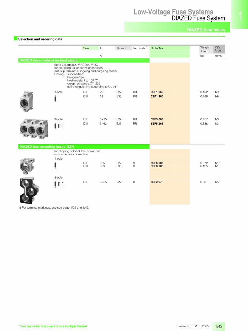
■ Selection and ordering data
1) For terminal markings, see see page 1/29 and 1/42.
Size In Thread Terminals 1) Order No. Weight PS*/P. unit1 item
A kg Items
DIAZED base made of molded plasticrated voltage 500 V AC/500 V DCfor mounting rail or screw connectionAnti-slip terminal at ingoing and outgoing feederCasing: silicone-free
halogen-freeheat-resistant to 150 °Ccreep resistance CTI 225self-extinguishing according to UL 94
1-pole DII 25 E27 RR 5SF1 060 0.152 1/9
DIII 63 E33 RR 5SF1 260 0.186 1/9
3-pole DII 3×25 E27 RR 5SF5 068 0.457 1/3
DIII 3×63 E33 RR 5SF5 268 0.538 1/3
DIAZED bus-mounting bases, EZRfor clipping onto 5SH3 5 power rail only for screw connection
1-pole
DII 25 E27 B 5SF6 005 0.072 1/15DIII 63 E33 B 5SF6 205 0.135 1/15
3-pole
DII 3×25 E27 B 5SF2 07 0.351 1/5
* You can order this quantity or a multiple thereof.

DIAZED fuse bases
1/44
DIAZED Fuse SystemLow-Voltage Fuse Systems
Siemens ET B1 T · 2005
■ Accessories
Size Thread Order No. Weight PS*/P. unit1 item
kg Items
Mounting partsDIAZED busbars with oblong holesapprox. 1000 mm long
cross-section: 12 mm × 2 mm, load capacity up to 80 Afor DII, sufficient for 25 bases, 5SH3 500 0.095 25
cross-section: 13 mm × 3 mm, load capacity up to 120 Afor DIII, sufficient for 19 bases 5SH3 501 0.180 25
Terminals, non-insulatedpin, for two conductors from 2 ×1.5 mm2 up to 16 mm2 5SH5 326 0.016 1/10
fork-type, for conductors up to 35 mm2 5SH3 502 0.010 25
Busbars for DIAZED EZR bus-mounting basessuitable for fork-type terminal connection, ready-made drilling with thread for screw adapters, approx. 2000 mm longcross-section: 16 mm x 3 mm, load capacity up to 150 A for lateral incoming supply
for DII sufficient for 42 5SF6 005 bases 5SH3 54 0.740 1/5for DII and DIII sufficient for 34 5SF6 205 bases 5SH3 55 0.740 1/5for DII sufficient for 27 5SF2 07 bases 5SH3 56 0.740 1/5
EZR bus-mounting terminalsnon-insulated
for conductors up to 16 mm2 8JH4 122 0.012 1for conductors up to 35 mm2 8JH4 124 0.024 1
DIAZED coversDIAZED cover made of molded plasticnot for SILIZED fuse links
1-pole
(5 DIAZED bases = 12 MW)DII E27 5SH2 032 0.017 1/20
(4 DIAZED bases = 12 MW)DIII E33 5SH2 232 0.020 1/20
Capsmolded plastic1-pole
NDz E16 5SH2 01 0.028 1/10DII E27 5SH2 02 0.038 1/20DIII E33 5SH2 22 0.048 1/20
DIV R1¼” 5SH2 40 0.115 1/5
Cover rings1-pole
molded plasticalso for bus-mounting base EZRDII E27 5SH3 401 0.013 5DIII E33 5SH3 411 0.014 5
ceramicDII and DIII also for bus-mounting base EZRNDz E16 5SH3 30 0.020 1/100DII E27 5SH3 32 0.029 10DIII E33 5SH3 34 0.035 10
* You can order this quantity or a multiple thereof.

DIAZED fuse bases
1/45
DIAZED Fuse SystemLow-Voltage Fuse Systems 1
345678910
1213
Siemens ET B1 T · 2005
■ Accessories
1) Suitable for a rated voltage of up to 750 V.
Size Thread for fuse Order No. Weight PS*/P. unitlinks 1 item
A kg Items
Screw adapters, adapter sleevesDIAZED screw adapters
NDz E16 2 5SH3 28 0.002 104 5SH3 31 0.002 106 5SH3 05 0.002 10
10 5SH3 06 0.002 1016 5SH3 07 0.002 10
also for mounting in DIAZED base DIII
DII 1) E27 2 5SH3 10 0.015 104 5SH3 11 0.015 106 5SH3 12 0.015 10
10 5SH3 13 0.015 1016 5SH3 14 0.014 1020 5SH3 15 0.012 10
25 5SH3 16 0.012 10
DIII 1) E33 35 5SH3 17 0.019 1050 5SH3 18 0.018 1063 5SH3 20 0.017 10
DIAZED adapter sleevesfor DIV bases
DIV R1¼” 80 5SH3 21 0.006 10100 5SH3 22 0.005 10
DIAZED adapter sleevesfor snapping onto DIAZED screw caps,if E16 DIAZED fuse linksare inserted in DII DIAZED bases 5SH3 01 0.012 10
if DII DIAZED fuse linksare inserted in DIII DIAZED bases 5SH3 02 0.023 10
DIAZED adapter sleeve fitter for DII/DIII 5SH3 703 0.025 1
* You can order this quantity or a multiple thereof.

DIAZED fuse bases
1/46
DIAZED Fuse SystemLow-Voltage Fuse Systems
Siemens ET B1 T · 2005
■ Accessories
Size In Thread Order No. Weight PS*/P. unit1 item
A kg Items
DIAZED screw capsRated voltage 500 V AC/500 V DC
ceramic
NDz 25 E16 5SH1 11 0.016 5
molded plastic, with inspection hole, black,not for SILIZED fuse links
DII 25 E27 5SH1 221 0.026 5
DIII 63 E33 5SH1 231 0.042 5
narrow version, ceramic
DII 25 E27 5SH1 12 0.034 5
DIII 63 E33 5SH1 13 0.059 5
mushroom shape, ceramic, with inspection hole, sealable
DII 25 E27 5SH1 22 0.050 5
DIII 63 E33 5SH1 23 0.080 5
ceramic
DIV 100 R1¼” 5SH1 141 0.181 1
Rated voltage 750 V AC/750 V DC
only for 5SD6 DIAZED fuse linksand 5SF4 230 DIAZED fuse basesmade of ceramic, with fine thread
DIII 63 E33S 5SH1 161 0.084 1
Rated voltage 690 V AC/600 V DC
only for 5SD8 DIAZED fuse linksmade of ceramic, prolonged version
DIII 63 E33 5SH1 170 0.086 1
* You can order this quantity or a multiple thereof.

DIAZED fuse bases
1/47
DIAZED Fuse SystemLow-Voltage Fuse Systems 1
345678910
1213
Siemens ET B1 T · 2005
■ Dimensional drawings
DIAZED bases made of ceramic
DIAZED bases made of molded plastic
500 V AC/500 V DC1-pole5SF1
Version Type of connection
Dimensions
Type a b c d e �g h �I
NDz/25 A5SF1 012 KK 29 49 44.6 55 75 32 49 –5SF1 01 KK 29 49 44.6 55 75 32 49 4.2
DII/25 A5SF1 005 BB 38.4 41 46.6 53 83 34 63 –5SF1 024 BB 38.4 41 46.6 53 83 34 63 4.3
DIII/63 A5SF1 205 BS 45.5 46 47 54 83 43 78 –5SF1 215 SS 45.5 46 47 54 83 43 78 –5SF1 224 BS 45.5 46 47 54 83 43 78 4.35SF1 214 SS 45.5 46 47 54 83 43 78 4.3
DIV/100 A5SF1 401 flat termination 68 68 – 79 110 65 116 6.5
���������
�
��
�
�
�
�
750 V AC/750 V DC, for DIAZED fuse links 750 V AC1-pole, with cap5SF4 230
500 V AC/500 V DC3-pole, with cap, DII/DIII5SF5
Version DimensionsType a b c d e f g h
DII/3 x 25 A5SF5 067 106 106 48 – – 45 52 865SF5 066 106 106 48 32 5.2 45 52 86
DIII/3 x 63 A5SF5 237 127 130 54 – – 45 52 855SF5 236 127 130 54 32 5.2 45 52 85
��������
��
�
���
����
��
��������
�������
��
��
�
�
�
5SF1 060, 5SF1 2605SF5 068, 5SF5 268
Type Dimensionsa b
5SF1 060 40 –5SF1 260 50 –
5SF5 068 – 1205SF5 268 – 150
���
�������
�����
� ��

DIAZED fuse bases
1/48
DIAZED Fuse SystemLow-Voltage Fuse Systems
Siemens ET B1 T · 2005
■ Dimensional drawings
DIAZED bus-mounting bases, EZR
Mounting parts
5SF6 005 5SF6 205
5SF2 07
����
��
�
����
���� ���
��
������� ��
��
����
��
�
��������
��
�����
��
��
���
��
����
��
�
����
���� ���
��������
��
���� ���
�
���
������
����
����
���
��
��
����� ����
���� � ��������
Busbars for DIAZED EZR bus-mounting bases5SH3 54
5SH3 55
5SH3 56
������ �������
�
��
��������
�����
���� � � ��
�������
�
��
�����
��� �� ��� ��
�������
�
��
����� ��

DIAZED fuse bases
1/49
DIAZED Fuse SystemLow-Voltage Fuse Systems 1
345678910
1213
Siemens ET B1 T · 2005
■ Dimensional drawings
DIAZED covers
DIAZED screw caps
DIAZED cover made of molded plastic 5SH2
Size Type Dimensionsa b �c d
DII/E27 5SH2 032 41 51 27.5 19
DIII/E33 5SH2 232 52 51 34.5 18.5
Cap made of molded plastic 5SH2
Size Type Dimensionsa max. b max. c max. d max.
NDz/E16 5SH2 01 33 68 51.7 75
DII/E27 5SH2 02 43 74.7 53.6 83
DIII/E33 5SH2 22 51 90.5 53.6 83
DIV/R1¼” 5SH2 40 67 118 74.5 104
���������
�
�
�
�
� �
���������
Cover rings made of molded plastic5SH3
Size Type Dimensionsa b �c d
DII/E27 5SH3 401 39.5 35.5 33.5 17.5
DIII/E33 5SH3 411 49.5 45.5 41.5 17.5
NDz/E16 5SH3 30 30 26 26 16.5
DII/E27 5SH3 32 41.5 35 38 17.5
DIII/E33 5SH3 34 51.5 45 44 19
������ ��
� � �
5SH1
Size Type Dimensionsa �b
NDz/E16 5SH1 11 35 28
DII/E27 5SH1 221 42 335SH1 12 45.5 345SH1 22 43 39
DIII/E33 5SH1 231 42 405SH1 13 45.5 435SH1 23 47 45
750 V AC/750 V DC5SH1 161 48 48
DIII/E33S 690 V AC/600 V DC5SH1 170 68 43
DIV/R1¼” 5SH1 141 53 65
�
���������
�

Notes
1/50
DIAZED Fuse SystemLow-Voltage Fuse Systems
Siemens ET B1 T · 2005

Product overview
1/51
LV HRC Fuse SystemLow-Voltage Fuse Systems 1
345678910
1213
Siemens ET B1 T · 2005
Low-Voltage Fuse Systems
■ Overview
LV HRC fuse links
LV HRC SITOR fuse links
LV HRC fuse bases
LV HRC fuse switch disconnectors

Product overview
1/52
LV HRC Fuse SystemLow-Voltage Fuse Systems
Siemens ET B1 T · 2005
■ Overview
The product range
Areas of applicationLV HRC fuses are used for installation systems in non-residential, commercial and industrial buildings as well as in systems of power supply companies. They therefore protect essential building parts and installations.
Non-interchangeabilityLV HRC fuses are fuse systems to be operated by experts. There are no constructional requirements for a non-interchangeability of rated current and protection against contact. The components and auxiliary equipment is designed in a way as to ensure the safe replacement of LV HRC fuses or isolation of systems.
SizesLV HRC fuse links are available in the sizes 000, 00, 0, 1, 2, 3, 4 and 4a.
Utilization categoriesUtilization category gL/gG is available for cable and conductor protection and aM for short-circuit protection of switching devices and gR/aR.
LV HRC components:
LV HRC componentsLV HRC fuse links are made up of the following components:$ LV HRC fuse base from the SR60 busbar system% LV HRC fuse base for busbar mounting& LV HRC fuse base, 3-pole( LV HRC fuse base, 1-pole) LV HRC contact covers* LV HRC fuse link+ LV HRC signal detector, LV HRC phase barrier- LV HRC protective cover. LV HRC fuse bases with slewing equipment,
- for screw connection on mounting plate- for screw connection on busbar system - for claw fixing on busbar
/ LV HRC protective cover for LV HRC fuse bases with slewing equipment
0 LV HRC slewing equipment1 LV HRC fuse base cover2 LV HRC isolating link with insulated grip lugs3 LV HRC isolating link with non-insulated grip lugs4 LCV HRC fuse puller with sleeve5 LV HRC fuse puller
� � � �
� � � �
� � � �
���� ���� ����
������
�� ��
�� ��
�
�
�
�
�
�
�
�
�� �� �

Product overview
1/53
LV HRC Fuse SystemLow-Voltage Fuse Systems 1
345678910
1213
Siemens ET B1 T · 2005
■ Overview
LV HRC fuse links with combination alarm
Impaired viewA quick detection of failed fuse links in systems is often not possible. If they are mounted in fuse bases with slewing equipment or LV HRC switch disconnectors, the sight is often impaired.The LV HRC fuse links have a clearly visible center indicatorred: functioningwhite: not functioning
Better safe than sorryIn addition to this, the LV HRC fuse links are equipped with a front indicator on the top. This considerably improves the view of one or the other indicator.
The combination alarmSiemens LV HRC fuse links have a combination alarm, a combina-tion of center indicator and front indicator. Thus, a failed LV HRC fuse link can be detected from different directions.
Front indicatorFor standard applications which are characterized by freely acces-sible fuse links allowing an easy detection of failed fuse links, product series with front and without center indicators are available.
Insulated grip lugsInsulated grip lugs must be made of metal. They are integrated in the top and bottom covers of the fuse link and provide greater safety when replacing. The mark indicating that the grip lugs are insulated is shown below:
Silver-plated contact pinLV HRC fuse links are always equipped with silver-plated contact pins. This means that they are non-corroding and have less power loss.
LV HRC fuse links with combination alarm
LV HRC fuse links with front indicator
triggered not triggered
triggered not triggered

Product overview
1/54
LV HRC Fuse SystemLow-Voltage Fuse Systems
Siemens ET B1 T · 2005
■ Overview
Highly-automated manufacturing
An overview of the production line with integrated test stations
Automated manufacturing sequences guarantee quality and precision
Environmental protection is an ongoing task for today’s modern industrial society and requires action!
Environmentally compatible recycling of LV HRC/HV HRC fusesNational and global environmental problems - for example global warming, the destruction of the ozone layer, the deterioration of the ground and water resources - have all proven the necessity of com-mon action. The recycling law, which was enacted in Germany at the end of 1996, requires companies to recycle materials and thus to save resources.
Responsibility of the industryIndustry has been called upon to acknowledge its responsibility towards future generations and to take the initiative. Manufacturers of low-voltage and high-voltage fuses and high-voltage HRC fuses are very aware of this responsibility and are determined to focus more than ever on "protecting" the environment and taking care of our natural resources.
How is recycling organized?Acting on a Siemens AG initiative, various German manufacturers of LV/HV HRC fuses have formed the non-profit association "NH/HH-Recycling e.V." Taking into account the prevailing legal regulations, the committee aims to actively contribute towards the protection of the environment and its natural resources by supporting the proper recycling of fuse links.
How are fuses recycled in Germany?LV HRC and HV HRC fuse links without packaging will be accepted for recycling. Electrical wholesalers will provide Euro pallet boxes for this purpose. In the case of large quantities, Euro pallet boxes can also be delivered to you directly on-site. For further information, please contact our regional Siemens A&D ET sales managers.
Material recyclingThe used fuses are completely melted by an officially certified recy-cler. The copper and silver gained are put back into the materials cycle. Residual materials, such as slag, are used in road and dam building. The "NH/HH-Recycling e.V." association plans to donate any profits arising from these processes to non-profit organizations for the purpose of environmental research.Please help us: be a part of our initiative and ask for the signs that stand for the recycling of LV HRC fuses.
�� ��

LV HRC fuse links
1/55
LV HRC Fuse SystemLow-Voltage Fuse Systems 1
345678910
1213
Siemens ET B1 T · 2005
■ Technical specifications
LV HRC fuse links3NA6 ...-4/-4KK 3NA6 3NA7 3NA6... -6 3NA7... -6
Utilization category gL/gG
Rated voltage Un
Size 000 and 00 V AC – 500 690
V DC – 250
Sizes 1 and 2 V AC 400 500 690
V DC – 440
Rated current In A 10 ... 400 2 ... 400 2 ... 315
Rated breaking capacity kA AC 120
kA DC 25
Combination alarm yes
Insulated grip lugs yes – yes –
Non-insulated grip lugs – yes – yes
Contact pins non-corroding, silver-plated
Resistance to climate at 95% relative humidity °C -20 ... +50
Standards DIN VDE 0636-201, DIN VDE 0680-4, IEC 60269-1, -2-1, EN 60269-1
Dimensions DIN 43620
3NA3 3NA3... -6 3ND1 3ND2
Utilization category gL/gG aM
Rated voltage Un
Size 000 and 00 V AC 500 690 500 –
V DC 250 –
Sizes 1 and 2 V AC 500 690
V DC 440 –
Size 3 V AC 500 690
V DC 440 –
Size 4 (IEC design) and 4a V AC 500 –
V DC 440 –
Rated current In A 2 ... 1250 2 ... 500 6 ... 160, 500, 630 63 ... 400
Rated breaking capacity kA AC 120
Contact pins non-corroding, silver-plated
Front indicator (without center indicator) yes
Non-insulated grip lugs yes
Resistance to climate at 95% relative humidity °C -20 ... +50
Standards DIN VDE 0636-201, DIN VDE 0680-4, IEC 60269-1, -2-1, EN 60269-1
Dimensions DIN 43620
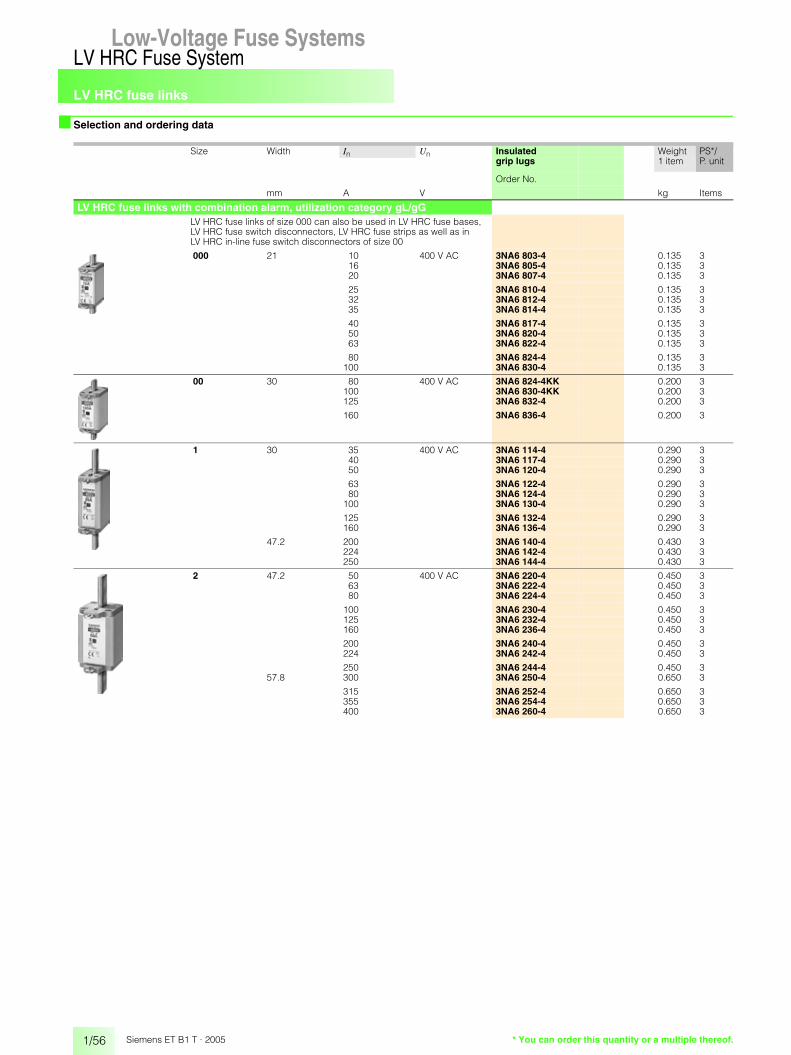
LV HRC fuse links
1/56
LV HRC Fuse SystemLow-Voltage Fuse Systems
Siemens ET B1 T · 2005 * You can order this quantity or a multiple thereof.
■ Selection and ordering data
Size Width In Un Insulated Weight PS*/P. unitgrip lugs 1 item
Order No.
mm A V kg Items
LV HRC fuse links with combination alarm, utilization category gL/gGLV HRC fuse links of size 000 can also be used in LV HRC fuse bases, LV HRC fuse switch disconnectors, LV HRC fuse strips as well as inLV HRC in-line fuse switch disconnectors of size 00
000 21 10 400 V AC 3NA6 803-4 0.135 316 3NA6 805-4 0.135 320 3NA6 807-4 0.135 3
25 3NA6 810-4 0.135 332 3NA6 812-4 0.135 335 3NA6 814-4 0.135 3
40 3NA6 817-4 0.135 350 3NA6 820-4 0.135 363 3NA6 822-4 0.135 3
80 3NA6 824-4 0.135 3100 3NA6 830-4 0.135 3
00 30 80 400 V AC 3NA6 824-4KK 0.200 3100 3NA6 830-4KK 0.200 3125 3NA6 832-4 0.200 3
160 3NA6 836-4 0.200 3
1 30 35 400 V AC 3NA6 114-4 0.290 340 3NA6 117-4 0.290 350 3NA6 120-4 0.290 3
63 3NA6 122-4 0.290 380 3NA6 124-4 0.290 3
100 3NA6 130-4 0.290 3
125 3NA6 132-4 0.290 3160 3NA6 136-4 0.290 3
47.2 200 3NA6 140-4 0.430 3224 3NA6 142-4 0.430 3250 3NA6 144-4 0.430 3
2 47.2 50 400 V AC 3NA6 220-4 0.450 363 3NA6 222-4 0.450 380 3NA6 224-4 0.450 3
100 3NA6 230-4 0.450 3125 3NA6 232-4 0.450 3160 3NA6 236-4 0.450 3
200 3NA6 240-4 0.450 3224 3NA6 242-4 0.450 3
250 3NA6 244-4 0.450 357.8 300 3NA6 250-4 0.650 3
315 3NA6 252-4 0.650 3355 3NA6 254-4 0.650 3400 3NA6 260-4 0.650 3

LV HRC fuse links
1/57
LV HRC Fuse SystemLow-Voltage Fuse Systems 1
345678910
1213
Siemens ET B1 T · 2005* You can order this quantity or a multiple thereof.
■ Selection and ordering data
Size Width In Un Non-insulated Insulated Weight PS*/P. unitgrip lugs grip lugs 1 item
Order No. Order No.
mm A V kg Items
LV HRC fuse links with combination alarm, utilization category gG
LV HRC fuse links of size 000 can also be used in LV HRC fuse bases, LV HRC fuse switch disconnectors, LV HRC fuse strips as well as inLV HRC in-line fuse switch disconnectors of size 00
The 300 A and 355 A fuse links do not conform to a VDE mark. They correspond to the standard, but are not permissible.
000 21 2 500 V AC/250 V DC
3NA7 802 3NA6 802 0.135 34 3NA7 804 3NA6 804 0.135 36 3NA7 801 3NA6 801 0.135 3
10 3NA7 803 3NA6 803 0.136 316 3NA7 805 3NA6 805 0.136 320 3NA7 807 3NA6 807 0.136 3
25 3NA7 810 3NA6 810 0.136 332 3NA7 812 3NA6 812 0.136 335 3NA7 814 3NA6 814 0.136 3
40 3NA7 817 3NA6 817 0.136 350 3NA7 820 3NA6 820 0.136 363 3NA7 822 3NA6 822 0.136 3
80 3NA7 824 3NA6 824 0.136 3100 3NA7 830 3NA6 830 0.136 3
00 30 80 500 V AC/250 V DC
3NA7 824-7 3NA6 824-7 0.211 3100 3NA7 830-7 3NA6 830-7 0.211 3125 3NA7 832 3NA6 832 0.211 3
160 3NA7 836 3NA6 836 0.211 3
1 30 16 500 V AC/440 V DC
3NA7 105 3NA6 105 0.290 320 3NA7 107 3NA6 107 0.290 325 3NA7 110 3NA6 110 0.290 3
35 3NA7 114 3NA6 114 0.290 340 3NA7 117 3NA6 117 0.290 350 3NA7 120 3NA6 120 0.290 3
63 3NA7 122 3NA6 122 0.290 380 3NA7 124 3NA6 124 0.290 3
100 3NA7 130 3NA6 130 0.290 3
125 3NA7 132 3NA6 132 0.290 3160 3NA7 136 3NA6 136 0.290 3
47.2 200 3NA7 140 3NA6 140 0.440 3224 3NA7 142 3NA6 142 0.440 3250 3NA7 144 3NA6 144 0.440 3
2 47.2 35 500 V AC/440 V DC
3NA7 214 3NA6 214 0.450 350 3NA7 220 3NA6 220 0.450 363 3NA7 222 3NA6 222 0.450 3
80 3NA7 224 3NA6 224 0.450 3100 3NA7 230 3NA6 230 0.450 3125 3NA7 232 3NA6 232 0.450 3
160 3NA7 236 3NA6 236 013 0.450 3200 3NA7 240 3NA6 240 013 0.450 3
224 3NA7 242 3NA6 242 013 0.450 3250 3NA7 244 3NA6 244 013 0.450 3
57.8 300 – 3NA6 250 013 0.641 3 315 3NA7 252 3NA6 252 013 0.660 3
355 – 3NA6 254 013 0.641 3400 3NA7 260 3NA6 260 013 0.660 3

LV HRC fuse links
1/58
LV HRC Fuse SystemLow-Voltage Fuse Systems
Siemens ET B1 T · 2005 * You can order this quantity or a multiple thereof.
■ Selection and ordering data
Further versions on request.
Size Width In Un Non-insulated Insulated Weight PS*/P. unitgrip lugs grip lugs 1 item
Order No. Order No.
mm A V kg Items
LV HRC fuse links with combination alarm,utilization category gG
LV HRC fuse links of size 000 can also be used in LV HRC fuse bases, LV HRC fuse switch disconnectors, LV HRC fuse strips as well as inLV HRC in-line fuse switch disconnectors of size 00
The 300 A fuse links do not conform to a VDE mark. They correspond to the standard, but are not permissible.
000 21 2 690 V AC/250 V DC
3NA7 802-6 3NA6 802-6 0.136 34 3NA7 804-6 3NA6 804-6 0.136 36 3NA7 801-6 3NA6 801-6 0.136 3
10 3NA7 803-6 3NA6 803-6 0.136 316 3NA7 805-6 3NA6 805-6 0.136 320 3NA7 807-6 3NA6 807-6 0.136 3
25 3NA7 810-6 3NA6 810-6 0.136 332 3NA7 812-6 3NA6 812-6 0.136 335 3NA7 814-6 3NA6 814-6 0.136 3
00 30 40 690 V AC/250 V DC
3NA7 817-6 3NA6 817-6 0.211 350 3NA7 820-6 3NA6 820-6 0.211 363 3NA7 822-6 3NA6 822-6 0.211 3
80 3NA7 824-6 3NA6 824-6 0.211 3100 3NA7 830-6 3NA6 830-6 0.211 3
1 30 50 690 V AC/, 440 V DC
3NA7 120-6 3NA6 120-6 0.290 363 3NA7 122-6 3NA6 122-6 0.290 380 3NA7 124-6 3NA6 124-6 0.290 3
100 3NA7 130-6 3NA6 130-6 0.290 3125 3NA7 132-6 3NA6 132-6 0.290 3160 3NA7 136-6 3NA6 136-6 0.290 3
47.2 200 3NA7 140-6 3NA6 140-6 0.440 3
2 47.2 80 690 V AC/440 V DC
3NA7 224-6 3NA6 224-6 0.450 3100 3NA7 230-6 3NA6 230-6 0.450 3125 3NA7 232-6 3NA6 232-6 0.450 3
160 3NA7 236-6 3NA6 236-6 0.450 3200 3NA7 240-6 3NA6 240-6 0.450 3
57.8 224 3NA7 242-6 3NA6 242-6 0.660 3250 3NA7 244-6 3NA6 244-6 0.660 3
300 3NA7 250-6 3NA6 250-6 0.660 3315 3NA7 252-6 3NA6 252-6 0.660 3

LV HRC fuse links
1/59
LV HRC Fuse SystemLow-Voltage Fuse Systems 1
345678910
1213
Siemens ET B1 T · 2005* You can order this quantity or a multiple thereof.
■ Selection and ordering data
Size Width In Un Non-insulated Weight PS*/P. unitgrip lugs 1 item
Order No.
mm A V kg Items
LV HRC fuse links with front indicator, utilization category gL/gGLV HRC fuse links of size 000 can also be used in LV HRC fuse bases, LV HRC fuse switch disconnectors, LV HRC fuse strips as well as inLV HRC in-line fuse switch disconnectors of size 00
000 21 2 500 V AC/ 250 V DC
3NA3 802 0.133 34 3NA3 804 0.133 36 3NA3 801 0.133 3
10 3NA3 803 0.133 316 3NA3 805 0.133 320 3NA3 807 0.133 3
25 3NA3 810 0.133 332 3NA3 812 0.133 335 3NA3 814 0.133 3
40 3NA3 817 0.133 350 3NA3 820 0.133 363 3NA3 822 0.133 3
80 3NA3 824 0.133 3100 3NA3 830 0.133 3
00 30 35 500 V AC/ 250 V DC
3NA3 814-7 0.200 350 3NA3 820-7 0.200 363 3NA3 822-7 0.200 3
80 3NA3 824-7 0.200 3100 3NA3 830-7 0.200 3125 3NA3 832 0.217 3
160 3NA3 836 0.217 3
0 30 6 500 V AC/ 3NA3 001 0.340 310 440 V DC 3NA3 003 0.340 316 3NA3 005 0.340 3
20 3NA3 007 0.340 325 3NA3 010 0.340 332 3NA3 012 0.340 3
35 3NA3 014 0.340 340 3NA3 017 0.340 350 3NA3 020 0.340 3
63 3NA3 022 0.340 380 3NA3 024 0.340 3
100 3NA3 030 0.340 3
125 3NA3 032 0.340 3160 3NA3 036 0.340 3
1 30 16 500 V AC/ 3NA3 105 0.290 320 440 V DC 3NA3 107 0.290 325 3NA3 110 0.290 3
35 3NA3 114 0.300 340 3NA3 117 0.300 350 3NA3 120 0.300 3
63 3NA3 122 0.300 380 3NA3 124 0.300 3
100 3NA3 130 0.300 3
125 3NA3 132 0.300 3160 3NA3 136 0.300 3
47.2 200 3NA3 140 0.440 3224 3NA3 142 0.440 3250 3NA3 144 0.440 3

LV HRC fuse links
1/60
LV HRC Fuse SystemLow-Voltage Fuse Systems
Siemens ET B1 T · 2005 * You can order this quantity or a multiple thereof.
■ Selection and ordering data
Size Width In Un Non-insulated Weight PS*/P. unitgrip lugs 1 item
Order No.
mm A V kg Items
LV HRC fuse links with front indicator, utilization category gL/gGThe 300 A, 355 A and 425 A fuse links do not conform to a VDE mark. They correspond to the standard, but are not permissible.
Fuse Links, size 4a can only be installed in 3NH7 520 LV HRC fuse base,size 4a.
2 47.2 35 500 V AC/ 3NA3 214 0.453 350 440 V DC 3NA3 220 0.453 363 3NA3 222 0.453 3
80 3NA3 224 0.453 3100 3NA3 230 0.453 3125 3NA3 232 0.453 3
160 3NA3 236 0.453 3200 3NA3 240 0.453 3
224 3NA3 242 0.453 3250 3NA3 244 0.453 3
57.8 300 3NA3 250 0.647 3315 3NA3 252 0.647 3
355 3NA3 254 0.647 3400 3NA3 260 0.647 3
3 57.8 200 500 V AC/ 3NA3 340 0.647 3224 440 V DC 3NA3 342 0.640 3250 3NA3 344 0.647 3
300 3NA3 350 0.647 3315 3NA3 352 0.647 3
355 3NA3 354 0.647 3400 3NA3 360 0.647 3
71.2 425 3NA3 362 1.000 3500 3NA3 365 1.000 3630 3NA3 372 1.000 3
4 101.8 630 500 V AC/ 3NA3 472 2.500 1(IEC design) 800 440 V DC 3NA3 475 2.500 1
1000 3NA3 480 2.500 1
1250 3NA3 482 2.500 1
4 A 101.8 500 500 V AC/ 3NA3 665 2.700 1630 440 V DC 3NA3 672 2.700 1800 3NA3 675 2.700 1
1000 3NA3 680 2.840 11250 3NA3 682 2.840 1

LV HRC fuse links
1/61
LV HRC Fuse SystemLow-Voltage Fuse Systems 1
345678910
1213
Siemens ET B1 T · 2005* You can order this quantity or a multiple thereof.
■ Selection and ordering data
Size Width In Un Non-insulated Weight PS*/P. unitgrip lugs 1 item
Order No.
mm A V kg Items
LV HRC fuse links with front indicator, utilization category gL/gGThe 300 A and 425 A fuse links do not conform to a VDE mark. They correspond to the standard, but are not permissible.
000 21 2 690 V AC/250 V DC
3NA3 802-6 0.135 34 3NA3 804-6 0.135 36 3NA3 801-6 0.135 3
10 3NA3 803-6 0.135 316 3NA3 805-6 0.135 320 3NA3 807-6 0.135 3
25 3NA3 810-6 0.135 332 3NA3 812-6 0.135 335 3NA3 814-6 0.135 3
00 30 40 690 V AC/250 V DC
3NA3 817-6 0.200 350 3NA3 820-6 0.200 363 3NA3 822-6 0.200 3
80 3NA3 824-6 0.200 3100 3NA3 830-6 0.200 3
1 30 50 690 V AC/440 V DC
3NA3 120-6 0.290 363 3NA3 122-6 0.290 380 3NA3 124-6 0.290 3
100 3NA3 130-6 0.290 3125 3NA3 132-6 0.290 3160 3NA3 136-6 0.290 3
47.2 200 3NA3 140-6 0.426 3
2 47.2 80 690 V AC/440 V DC
3NA3 224-6 0.426 3100 3NA3 230-6 0.426 3125 3NA3 232-6 0.426 3
160 3NA3 236-6 0.426 3200 3NA3 240-6 0.426 3
57.8 224 3NA3 242-6 0.660 3250 3NA3 244-6 0.680 3
300 3NA3 250-6 0.660 3315 3NA3 252-6 0.680 3
3 57.8 250 690 V AC/440 V DC
3NA3 344-6 0.660 3315 3NA3 352-6 0.660 3
71.2 355 3NA3 354-6 1.000 3400 3NA3 360-6 1.000 3
425 3NA3 362-6 1.000 3500 3NA3 365-6 1.000 3
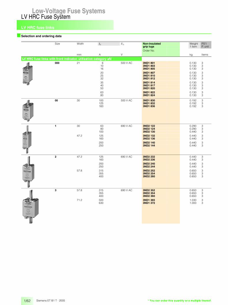
LV HRC fuse links
1/62
LV HRC Fuse SystemLow-Voltage Fuse Systems
Siemens ET B1 T · 2005 * You can order this quantity or a multiple thereof.
■ Selection and ordering data
Size Width In Un Non-insulated Weight PS*/P. unitgrip lugs 1 item
Order No.
mm A V kg Items
LV HRC fuse links with front indicator, utilization category aM000 21 6 500 V AC 3ND1 801 0.130 3
10 3ND1 803 0.130 316 3ND1 805 0.130 3
20 3ND1 807 0.130 325 3ND1 810 0.130 332 3ND1 812 0.130 3
35 3ND1 814 0.130 340 3ND1 817 0.130 350 3ND1 820 0.130 3
63 3ND1 822 0.130 380 3ND1 824 0.130 3
00 30 100 500 V AC 3ND1 830 0.192 3125 3ND1 832 0.192 3160 3ND1 836 0.192 3
1 30 63 690 V AC 3ND2 122 0.290 380 3ND2 124 0.290 3
100 3ND2 130 0.440 3
47.2 125 3ND2 132 0.440 3160 3ND2 136 0.440 3
200 3ND2 140 0.440 3250 3ND2 144 0.440 3
2 47.2 125 690 V AC 3ND2 232 0.440 3160 3ND2 236 0.440 3
200 3ND2 240 0.440 3250 3ND2 244 0.440 3
57.8 315 3ND2 252 0.650 3355 3ND2 254 0.650 3400 3ND2 260 0.650 3
3 57.8 315 690 V AC 3ND2 352 0.650 3355 3ND2 354 0.650 3400 3ND2 360 0.650 3
71.2 500 3ND1 365 1.030 3630 3ND1 372 1.000 3
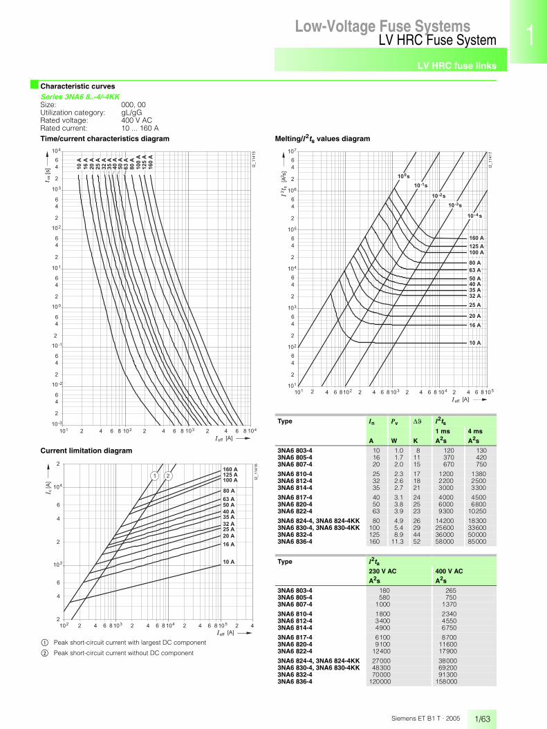
LV HRC fuse links
1/63
LV HRC Fuse SystemLow-Voltage Fuse Systems 1
345678910
1213
Siemens ET B1 T · 2005
■ Characteristic curvesSeries 3NA6 8..-4/-4KKSize: 000, 00Utilization category: gL/gGRated voltage: 400 V ACRated current: 10 ... 160 ATime/current characteristics diagram
Current limitation diagram
Melting/I2ts values diagram
�� � �
� � � �
�
�
�
� � � �
�� � � �� � �� � � �� � �
�
�
�
� � � �
�
�
�
� � �
�
�
�
� � �
�
�
�
� � �
�
�
�
� � �
�
�
�
� � �
������
� � � ��
�
� � � � � �
� � ����
����
����
����
����
����
���
����
����
���
�����
�����
�����
� � � � �� � ��
� �
�
�
�
� � � � �
� � � � �
�
�
�
�
� � �
� � � �
� � � �
� � � �
� � � � �
� � � �
� � � �
� � � �
� � � �
�
� � � � � �
���
� � �
�
� � �� � �� � � �� � �� � � �
� � �
� � � �
������
� �
$ Peak short-circuit current with largest DC component
% Peak short-circuit current without DC component
Type In Pv �� I2ts1 ms 4 ms
A W K A2s A2s
3NA6 803-4 10 1.0 8 120 1303NA6 805-4 16 1.7 11 370 4203NA6 807-4 20 2.0 15 670 750
3NA6 810-4 25 2.3 17 1200 13803NA6 812-4 32 2.6 18 2200 25003NA6 814-4 35 2.7 21 3000 3300
3NA6 817-4 40 3.1 24 4000 45003NA6 820-4 50 3.8 25 6000 68003NA6 822-4 63 3.9 23 9300 10250
3NA6 824-4, 3NA6 824-4KK 80 4.9 26 14200 183003NA6 830-4, 3NA6 830-4KK 100 5.4 29 25600 336003NA6 832-4 125 8.9 44 36000 500003NA6 836-4 160 11.3 52 58000 85000
Type I2ta230 V AC 400 V AC
A2s A2s
3NA6 803-4 180 2653NA6 805-4 580 7503NA6 807-4 1000 1370
3NA6 810-4 1800 23403NA6 812-4 3400 45503NA6 814-4 4900 6750
3NA6 817-4 6100 87003NA6 820-4 9100 116003NA6 822-4 12400 17900
3NA6 824-4, 3NA6 824-4KK 27000 380003NA6 830-4, 3NA6 830-4KK 48300 692003NA6 832-4 70000 913003NA6 836-4 120000 158000
� � � �� � �� � �� � � �� � �� � � �� �� � � � �� ��� �
�
�
�
� �
�
�
�
� �
�
�
�
� �
�
�
�
� �
�
�
�
� �
�
�
�
� �
������
� � � � � �
�
��� �
�
�
�
�
�
�
�
�
� � � �
� � � � �
� � � � �
� � � � �
� ���
� � � �
� � � �
� � � �
� � � �
� � � �
� � � �
� � �
� � � �
� � � �
� � �
� � � � �
� � � � �
� � � � �

LV HRC fuse links
1/64
LV HRC Fuse SystemLow-Voltage Fuse Systems
Siemens ET B1 T · 2005
■ Characteristic curves
Series 3NA6 1..-4Size: 1Utilization category: gL/gGRated voltage: 400 V ACRated current: 35 ... 250 ATime/current characteristics diagram
Current limitation diagram
$ Peak short-circuit current with largest DC component
% Peak short-circuit current without DC component
Melting/I2ts values diagram
��� � � ��
� � � �
�
�
�
� � � �
�� � � �� � �� � � �� � �
�
�
�
� � � �
�
�
�
� � �
�
�
�
� � �
�
�
�
� � �
�
�
�
� � �
�
�
�
� � �
������
����
���
����
����
���
�����
�����
�����
�
� � � � � �
� � �����
����
�����
� � � � �� � ��
� �
�
�
�
�
�
�
�
�
� � � � � �
���
� � �
� � �
� � �� � �� � � �� � �� � � �
������
� � � �
� � � � �
� � � � �
� � � � �
� � � �
� � � � �
� � � � �
� � �
� �
� � �
� � � �
� � � �
Type In Pv ��
A W K
3NA6 114-4 35 3.2 163NA6 117-4 40 3.6 163NA6 120-4 50 4.6 20
3NA6 122-4 63 6.0 213NA6 124-4 80 7.5 293NA6 130-4 100 8.9 30
3NA6 132-4 125 10.7 313NA6 136-4 160 13.9 343NA6 140-4 200 15.0 36
3NA6 142-4 224 16.1 373NA6 144-4 250 17.3 39
Type I2ts I2ta1 ms 4 ms 230 V AC 400 V AC
A2s A2s A2s A2s
3NA6 114-4 3000 3300 4900 67503NA6 117-4 4000 4500 6100 87003NA6 120-4 6000 6800 9100 11600
3NA6 122-4 7700 9800 14200 190003NA6 124-4 12000 16000 23100 307003NA6 130-4 24000 30600 40800 56200
3NA6 132-4 36000 50000 70000 913003NA6 136-4 58000 85000 120000 1580003NA6 140-4 115000 135000 218000 285000
3NA6 142-4 145000 170000 299000 3920003NA6 144-4 205000 230000 420000 551000
� � � �� � �� � �� � � �� � �� � � �� �� � � � �� ��� �
�
�
�
� �
�
�
�
� �
�
�
�
� �
�
�
�
� �
�
�
�
� �
�
�
�
� �
������
� � � � � �
�
��� �
�
�
�
�
�
�
�
�
� � � �
� � �
� � � �
� � � � �
� � � � �
� � � � �
� � � � �
� � � �
� � � � �
� � � �
� � �
� � � �
� � � � �
� � � � �
� � � � �
� ���
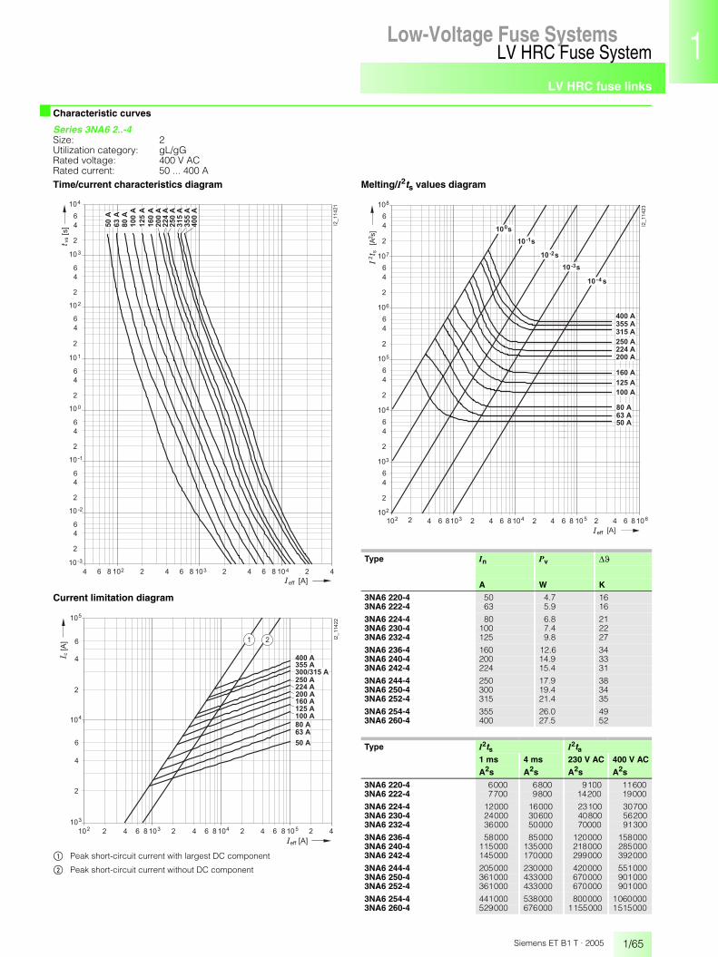
LV HRC fuse links
1/65
LV HRC Fuse SystemLow-Voltage Fuse Systems 1
345678910
1213
Siemens ET B1 T · 2005
■ Characteristic curves
Series 3NA6 2..-4Size: 2Utilization category: gL/gGRated voltage: 400 V ACRated current: 50 ... 400 ATime/current characteristics diagram
Current limitation diagram
$ Peak short-circuit current with largest DC component
% Peak short-circuit current without DC component
Melting/I2ts values diagram
��� � � ��
� � � �
�
�
�
� � � �
�� � � �� � �� � � �� � �
�
�
�
� � � �
�
�
�
� � �
�
�
�
� � �
�
�
�
� � �
�
�
�
� � �
�
�
�
� � �
������
�
� � � � � �
� � ����
����
���
�����
�����
�����
�����
����
�����
�����
�����
����
� � � � �� � ��
� �
�
�
�
�
�
�
�
�
� � � � � �
���
� � �
� � �
� � �� � �� � � �� � �� � � �
������
� �
� � � �
� � � �
� � � � �
� � � � �
� � � �
� � � � �
� � � � � � � �
� � � � �
� � � �
� � � � �
� � � � �
� � �
Type In Pv ��
A W K
3NA6 220-4 50 4.7 163NA6 222-4 63 5.9 16
3NA6 224-4 80 6.8 213NA6 230-4 100 7.4 223NA6 232-4 125 9.8 27
3NA6 236-4 160 12.6 343NA6 240-4 200 14.9 333NA6 242-4 224 15.4 31
3NA6 244-4 250 17.9 383NA6 250-4 300 19.4 343NA6 252-4 315 21.4 35
3NA6 254-4 355 26.0 493NA6 260-4 400 27.5 52
Type I2ts I2ta1 ms 4 ms 230 V AC 400 V AC
A2s A2s A2s A2s
3NA6 220-4 6000 6800 9100 116003NA6 222-4 7700 9800 14200 19000
3NA6 224-4 12000 16000 23100 307003NA6 230-4 24000 30600 40800 562003NA6 232-4 36000 50000 70000 91300
3NA6 236-4 58000 85000 120000 1580003NA6 240-4 115000 135000 218000 2850003NA6 242-4 145000 170000 299000 392000
3NA6 244-4 205000 230000 420000 5510003NA6 250-4 361000 433000 670000 9010003NA6 252-4 361000 433000 670000 901000
3NA6 254-4 441000 538000 800000 10600003NA6 260-4 529000 676000 1155000 1515000
� � � �� � �� � �� � � �� � �� � � �� �� � � � �� ��� �
�
�
�
� �
�
�
�
� �
�
�
�
� �
�
�
�
� �
�
�
�
� �
�
�
�
� �
������
� � � � � �
�
��� �
�
�
�
�
�
�
�
�
� � � �
� � � � �
� � � � �
� � � � �
� ���
� � � �
� � � �
� � �
� � � � �
� � � � �
� � � � �
� � � � �
� � � �
� � � � �
� � � � �
� � � � �
� � � �

LV HRC fuse links
1/66
LV HRC Fuse SystemLow-Voltage Fuse Systems
Siemens ET B1 T · 2005
■ Characteristic curves
Series 3NA3 8, 3NA6 8, 3NA7 8Size: 000, 00Utilization category: gL/gGRated voltage: 500 V AC/250 V DCRated current: 2 ... 160 ATime/current characteristics diagram
Current limitation diagram
$ Peak short-circuit current with largest DC component
% Peak short-circuit current without DC component
Melting/I2ts values diagram
��� � � ��
� � � �
�
�
�
� � � �
�� � � �� � �� � � �� � �
�
�
�
� � � �
�
�
�
� � �
�
�
�
� � �
�
�
�
� � �
�
�
�
� � �
�
�
�
� � �
�������
����
���
���
����
����
����
����
����
���
����
����
���
�����
�����
�����
��
�
� � � � � �
� �
� � � � �� � ��
� �
�
�
�
� � � � �
� � � � �
�
�
�
�
� � �
� � � �
� � � �
� � � �
� �
� � � � �
� � � �
� � � �
� � � �
� � � �
� � �
� � �
�
� � � � � �
��� � � �
�
� � �
� � �� � �� � � �� � �� � � �
� �
� � �
� � � �
�������
� � � �� � �� � �� � � �� � �� � � �� �� � � � �� ��� �
�
�
�
� � � � �
� � � � �
� � � � �
� � �
� � � �
� � � �
� � �
� � � �
� � � �
� � � �
� � � �
� � � �
� � � �
� �
� � �
� ���
� �� ��
� �� ��
� �� ��
� �� �
� �
�
�
�
� �
�
�
�
� �
�
�
�
� �
�
�
�
� �
�
�
�
� �
�������
� � �
� � � � � �
�
��� �
�
�
�
�
�
�
�
�

LV HRC fuse links
1/67
LV HRC Fuse SystemLow-Voltage Fuse Systems 1
345678910
1213
Siemens ET B1 T · 2005
■ Characteristic curves
Series 3NA3 8, 3NA6 8, 3NA7 8Size: 000, 00Utilization category: gL/gGRated voltage: 500 V AC/250 V DCRated current: 2 ... 160 A
Type In Pv �� I2ts I2ta1 ms 4 ms 230 V AC 400 V AC 500 V AC
A W K A2s A2s A2s A2s A2s
3NA3 802, 3NA6 802, 3NA7 802 2 1.3 8 2 2 4 6 93NA3 804, 3NA6 804, 3NA7 804 4 0.9 6 11 13 18 22 273NA3 801, 3NA6 801, 3NA7 801 6 1.3 8 46 50 80 110 150
3NA3 803, 3NA6 803, 3NA7 803 10 1 8 120 130 180 265 3703NA3 805, 3NA6 805, 3NA7 805 16 1.7 11 370 420 580 750 10003NA3 807, 3NA6 807, 3NA7 807 20 2 15 670 750 1000 1370 1900
3NA3 810, 3NA6 810, 3NA7 810 25 2.3 17 1 200 1380 1800 2340 33003NA3 812, 3NA6 812, 3NA7 812 32 2.6 18 2200 2400 3400 4550 64003NA3 814, 3NA3 814-7, 3NA6 814, 3NA7 814 35 2.7 21 3000 3300 4900 6750 9300
3NA3 817, 3NA6 817, 3NA7 817 40 3.1 24 4000 4500 6100 8700 121003NA3 820, 3NA3 820-7, 3NA6 820, 3NA7 820 50 3.8 25 6000 6800 9100 11600 160003NA3 822, 3NA3 822-7, 3NA6 822, 3NA7 822 63 4.6 28 7700 9800 14200 19000 26500
3NA3 824, 3NA3 824-7, 3NA6 824, 3NA6 824-7, 3NA7 824, 3NA7 824-7
80 5.8 33 12000 16000 23100 30700 43000
3NA3 830, 3NA3 830-7, 3NA6 830, 3NA6 830-7, 3NA7 830, 3NA7 830-7
100 6.6 34 24000 30600 40800 56200 80000
3NA3 832, 3NA6 832, 3NA7 832 125 8.9 44 36000 50000 70000 91300 1300003NA3 836, 3NA6 836, 3NA7 836 160 11.3 52 58000 85000 120000 158000 223000

LV HRC fuse links
1/68
LV HRC Fuse SystemLow-Voltage Fuse Systems
Siemens ET B1 T · 2005
■ Characteristic curves
Series 3NA3 0Size: 0Utilization category: gL/gGRated voltage: 500 V AC/440 V DCRated current: 6 ... 160 ATime/current characteristics diagram
Current limitation diagram
$ Peak short-circuit current with largest DC component
% Peak short-circuit current without DC component
Melting/I2ts values diagram
�� � �
� � � �
�
�
�
� � � �
�� � � �� � �� � � �� � �
�
�
�
� � � �
�
�
�
� � �
�
�
�
� � �
�
�
�
� � �
�
�
�
� � �
�
�
�
� � �
�������
� � � ��
���
����
����
����
����
���
�����
�����
�����
����
����
���
����
����
�
� � � � � �
� �
� � � � �� � ��
� �
�
�
�
� � � � �
� � � � �
�
�
�
�
� � �
� � � �
� � � �
� � � �
� � � � �
� � � �
� � � �
� � � �
� � � �
� � �
�
� � � � � �
���
� � �
�
� � �� � �� � � �� � �� � � �
� � �
� � � �
�������
� �
Type In Pv �� I2ts1 ms 4 ms
A W K A2s A2s
3NA3 001 6 1.5 6 46 503NA3 003 10 1 9 120 1303NA3 005 16 1.9 11 370 420
3NA3 007 20 2.3 13 670 7503NA3 010 25 2.7 15 1200 13803NA3 012 32 3 13 2200 2400
3NA3 014 35 3 17 3000 33003NA3 017 40 3.4 17 4000 45003NA3 020 50 4.5 24 6000 6800
3NA3 022 63 5.8 27 7700 98003NA3 024 80 7 34 12000 160003NA3 030 100 8.2 37 24000 30600
3NA3 032 125 10.2 38 36000 500003NA3 036 160 13.5 44 58000 85000
Type I2ta230 V AC 400 V AC 500 V AC
A2s A2s A2s
3NA3 001 80 110 1503NA3 003 180 265 3703NA3 005 580 750 1000
3NA3 007 1000 1370 19003NA3 010 1800 2340 33003NA3 012 3400 4550 6400
3NA3 014 4900 6750 93003NA3 017 6100 8700 121003NA3 020 9100 11600 16000
3NA3 022 14200 19000 265003NA3 024 23100 30700 430003NA3 030 40800 56200 80000
3NA3 032 70000 91300 1300003NA3 036 120000 158000 223000
� � � �� � �� � �� � � �� � �� � � �� �� � � � �� ��� �
�
�
�
� �
�
�
�
� �
�
�
�
� �
�
�
�
� �
�
�
�
� �
�
�
�
� �
�������
�
�
�
�
�
�
�
� � � � �
� � � � �
� � �
� � � �
� � � �
� � �
� � � �
� � � �
� � � �
� � � �
� � � � �
� � �
� � �
� � � �
� ���
� �� ��
� �� ��
� �� ��
� �� �
� � � � � �
�
��� �
�

LV HRC fuse links
1/69
LV HRC Fuse SystemLow-Voltage Fuse Systems 1
345678910
1213
Siemens ET B1 T · 2005
■ Characteristic curves
Series 3NA3 1, 3NA6 1, 3NA7 1Size: 1Utilization category: gL/gGRated voltage: 500 V AC/440 V DCRated current: 16 ... 250 ATime/current characteristics diagram
Current limitation diagram
$ Peak short-circuit current with largest DC component
% Peak short-circuit current without DC component
Melting/I2ts values diagram
�� � �
� � � �
�
�
�
� � � �
�� � � �� � �� � � �� � �
�
�
�
� � � �
�
�
�
� � �
�
�
�
� � �
�
�
�
� � �
�
�
�
� � �
�
�
�
� � �
�������
� � � ��
����
����
����
���
�����
�����
�����
����
���
����
����
�����
����
�����
�
� � � � � �
� �
� � � � �� � ��
� �
�
�
� � � � �
� � � � �
�
�
�
�
� � �
� � � �
� � � � �
� � � �
� � � �
� � � �
� � � �
�
� � � � � �
���
� � �
�
� � �� � �� � � �� � �� � � �
� � �
� � � �
��������
� � � � �
� � � �
� � � � �� �
Type In Pv �� I2ts1 ms 4 ms
A W K A2s A2s
3NA3 105, 3NA6 105, 3NA7 105 16 2.1 8 370 4203NA3 107, 3NA6 107, 3NA7 107 20 2.4 10 670 7503NA3 110, 3NA6 110, 3NA7 110 25 2.8 11 1200 1380
3NA3 114, 3NA6 114, 3NA7 114 35 3.2 16 3000 33003NA3 117, 3NA6 117, 3NA7 117 40 3.6 16 4000 45003NA3 120, 3NA6 120, 3NA7 120 50 4.6 20 6000 6800
3NA3 122, 3NA6 122, 3NA7 122 63 6 21 7700 98003NA3 124, 3NA6 124, 3NA7 124 80 7.5 29 12000 160003NA3 130, 3NA6 130, 3NA7 130 100 8.9 30 24000 30600
3NA3 132, 3NA6 132, 3NA7 132 125 10.7 31 36000 500003NA3 136, 3NA6 136, 3NA7 136 160 13.9 34 58000 850003NA3 140, 3NA6 140, 3NA7 140 200 15 36 115000 135000
3NA3 142, 3NA6 142, 3NA7 142 224 16.1 37 145000 1700003NA3 144, 3NA6 144, 3NA7 144 250 17.3 39 205000 230000
Type I2ta230 V AC 400 V AC 500 V AC
A2s A2s A2s
3NA3 105, 3NA6 105, 3NA7 105 580 750 10003NA3 107, 3NA6 107, 3NA7 107 1000 1370 19003NA3 110, 3NA6 110, 3NA7 110 1800 2340 3300
3NA3 114, 3NA6 114, 3NA7 114 4900 6750 93003NA3 117, 3NA6 117, 3NA7 117 6100 8700 121003NA3 120, 3NA6 120, 3NA7 120 9100 11600 16000
3NA3 122, 3NA6 122, 3NA7 122 14200 19000 265003NA3 124, 3NA6 124, 3NA7 124 23100 30700 430003NA3 130, 3NA6 130, 3NA7 130 40800 56200 80000
3NA3 132, 3NA6 132, 3NA7 132 70000 91300 1300003NA3 136, 3NA6 136, 3NA7 136 120000 158000 2230003NA3 140, 3NA6 140, 3NA7 140 218000 285000 400000
3NA3 142, 3NA6 142, 3NA7 142 299000 392000 5500003NA3 144, 3NA6 144, 3NA7 144 420000 551000 780000
� � � �� � �� � �� � � �� � �� � � �� �� � � � �� ��� �
�
�
�
� �
�
�
�
� �
�
�
�
� �
�
�
�
� �
�
�
�
� �
�
�
�
� �
�������
�
�
�
�
�
�
�
�
� �� ��
� ���
� �� ��
� �� ��
� �� �
� � � � �
� � � � �
� � �
� � � �
� � � �
� � �
� � � �
� � � �
� � � �
� � � �
� � � � �
� � � � �
� � � �
� � � � �
� � � � � �
�
��� �
�

LV HRC fuse links
1/70
LV HRC Fuse SystemLow-Voltage Fuse Systems
Siemens ET B1 T · 2005
■ Characteristic curves
Series 3NA3 2, 3NA6 2, 3NA7 2Size: 2Utilization category: gL/gGRated voltage: 500 V AC/440 V DCRated current: 35 ... 400 ATime/current characteristics diagram
Current limitation diagram
$ Peak short-circuit current with largest DC component
% Peak short-circuit current without DC component
Melting/I2ts values diagram
��� � � ��
� � � �
�
�
�
� � � �
�� � � �� � �� � � �� � �
�
�
�
� � � �
�
�
�
� � �
�
�
�
� � �
�
�
�
� � �
�
�
�
� � �
�
�
�
� � �
�������
����
����
���
�����
����
�
� � � � � �
� �
�����
�����
�����
����
�����
��� �����
�����
����
� � � � �� � ��
� �
� � � � �
� � � � �
�
�
�
�
� � � � �
� � � �
� � � �
�
� � � � � �
���
� � �
�
� � �� � �� � � �� � �� � � �
� � �
� � � �
�������
�
� � � � �
� � � �
� � � � �
�
� � � � � � � �
� � � � �
� � � �� �
Type In Pv �� I2ts1 ms 4 ms
A W K A2s A2s
3NA3 214, 3NA6 214, 3NA7 214 35 3.2 12 3000 33003NA3 220, 3NA6 220, 3NA7 220 50 4.7 16 6000 68003NA3 222, 3NA6 222, 3NA7 222 63 5.9 16 7700 9800
3NA3 224, 3NA6 224, 3NA7 224 80 6.8 21 12000 160003NA3 230, 3NA6 230, 3NA7 230 100 7.4 22 24000 306003NA3 232, 3NA6 232, 3NA7 232 125 9.8 27 36000 50000
3NA3 236, 3NA6 236, 3NA7 236 160 12.6 34 58000 850003NA3 240, 3NA6 240, 3NA7 240 200 14.9 33 115000 1350003NA3 242, 3NA6 242, 3NA7 242 224 15.4 31 145000 170000
3NA3 244, 3NA6 244, 3NA7 244 250 17.9 38 205000 2300003NA3 250, 3NA6 250 300 19.4 34 361000 4330003NA3 252, 3NA6 252, 3NA7 252 315 21.4 35 361000 433000
3NA3 254, 3NA6 254 355 26.0 49 441000 5380003NA3 260, 3NA6 260, 3NA7 260 400 27.5 52 529000 676000
Type I2ta230 V AC 400 V AC 500 V AC
A2s A2s A2s
3NA3 214, 3NA6 214, 3NA7 214 4900 6750 93003NA3 220, 3NA6 220, 3NA7 220 9100 11600 160003NA3 222, 3NA6 222, 3NA7 222 14200 19000 26500
3NA3 224, 3NA6 224, 3NA7 224 23100 30700 430003NA3 230, 3NA6 230, 3NA7 230 40800 56200 800003NA3 232, 3NA6 232, 3NA7 232 70000 91300 130000
3NA3 236, 3NA6 236, 3NA7 236 120000 158000 2230003NA3 240, 3NA6 240, 3NA7 240 218000 285000 4000003NA3 242, 3NA6 242, 3NA7 242 299000 392000 550000
3NA3 244, 3NA6 244, 3NA7 244 420000 551000 7800003NA3 250, 3NA6 250 670000 901000 12750003NA3 252, 3NA6 252, 3NA7 252 670000 901000 1275000
3NA3 254, 3NA6 254 800000 1060000 15000003NA3 260, 3NA6 260, 3NA7 260 1155000 1515000 2150000
� � � �� � �� � �� � � �� � �� � � �� �� � � � �� ��� �
�
�
�
� �
�
�
�
� �
�
�
�
� �
�
�
�
� �
�
�
�
� �
�
�
�
� �
�������
�
�
�
�
�
�
�
�
� � � � �
� � � � �
� � �
� � � �
� � � �
� � � � �
� � � �
� ���
� �� ��
� �� ��
� �� ��
� �� �
� � � � �
� � � �
� � � � �
� � � � � � � �
� � � � �
� � � �
� � � � � �
�
��� �
�

LV HRC fuse links
1/71
LV HRC Fuse SystemLow-Voltage Fuse Systems 1
345678910
1213
Siemens ET B1 T · 2005
■ Characteristic curves
Series 3NA3 3Size: 3Utilization category: gL/gGRated voltage: 500 V AC/440 V DCRated current: 200 ... 630 ATime/current characteristics diagram
Current limitation diagram
$ Peak short-circuit current with largest DC component
% Peak short-circuit current without DC component
Melting/I2ts values diagram
�� � �
� � � �
�
�
�
� � � �
�� � � �� � �� � � �� � �
�
�
�
� � � �
�
�
�
� � �
�
�
�
� � �
�
�
�
� � �
�
�
�
� � �
�
�
�
� � �
�������
� � � ��
� � � � �
� � � � �
� � � �
� � � �
� � � � �
� � � � � � � �
� � � � �
� � � �
�
� � � � � �
� �
� � � � �
� � � � �� � ��
� �
�
�
�
�
�
�
�
� � � � � �
���
� � �
� � �� � �� � � �� � �� �
�������
� � � � �
� � � � �
� � � � � � � �
� � � � �
� � � �
� � � �
� � � � �
� � � � �� �
� � � �
Type In Pv �� I2ts1 ms 4 ms
A W K A2s A2s
3NA3 340 200 14.9 32 115000 1350003NA3 342 224 15.4 31 145000 1700003NA3 344 250 17.9 36 205000 230000
3NA3 350 300 19.4 19 361000 4330003NA3 352 315 21.4 22 361000 4330003NA3 354 355 26.0 26 441000 538000
3NA3 360 400 27.5 28 529000 6760003NA3 362 425 26.5 34 650000 9700003NA3 365 500 36.5 41 785000 1270000
3NA3 372 630 44.0 50 1900000 2700000
Type I2ta230 V AC 400 V AC 500 V AC
A2s A2s A2s
3NA3 340 218000 285000 4000003NA3 342 299000 392000 5500003NA3 344 420000 551000 780000
3NA3 350 670000 901000 12750003NA3 352 670000 901000 12750003NA3 354 800000 1060000 1500000
3NA3 360 1155000 1515000 21500003NA3 362 1515000 1856000 22700003NA3 365 1915000 2260000 2700000
3NA3 372 3630000 4340000 5400000
� � � �� � �� � �� � � �� � �� � � �� �� � � � �� ��� �
�
�
�
� �
�
�
�
� �
�
�
�
� �
�
�
�
� �
�
�
�
� �
�
�
�
� �
�������
�
�
�
�
�
�
�
� � � � �
� � � � �
� � � � �
� � � �
� � � �
� � � � �
� � � � � � � �
� � � � � �
�
��� �
�
�
� ���
� �� ��
� �� ��
� �� ��
� �� �
� � � �
� � � � �

LV HRC fuse links
1/72
LV HRC Fuse SystemLow-Voltage Fuse Systems
Siemens ET B1 T · 2005
■ Characteristic curves
Series 3NA3 4Size: 4 (IEC design)Utilization category: gL/gGRated voltage: 500 V AC/440 V DCRated current: 630 ... 1000 ATime/current characteristics diagram
Current limitation diagram
$ Peak short-circuit current with largest DC component
% Peak short-circuit current without DC component
Melting/I2ts values diagram
�
�� � �
� � � �
�
�
�
� � � �
�� � � �� � �� � � �� � �
�
�
�
� � � �
�
�
�
� � �
�
�
�
� � �
�
�
�
� � �
�
�
�
� � �
�
�
�
� � �
�������
� � � ��
� � � � � �
� � � � � � �
� � � � � � �
� � � � � � � � � �
� � � � � �
� �
� � � � �� � ��
� �
�
�
�
�
�
� � � � � �
���
� � �
�
� � �� � �� �
�������
�
�
� � � � �
� �
� � � �
� � � � � �
� � � � � �
� � � � � � �
Type In Pv �� I2ts1 ms 4 ms
A W K A2s A2s
3NA3 472 630 47 37 1900000 27000003NA3 475 800 59 43 3480000 5620000
3NA3 480 1000 74 56 7920000 104000003NA3 482 1250 99 65 11880000 18200000
Type I2ta230 V AC 400 V AC 500 V AC
A2s A2s A2s
3NA3 472 3630000 4340000 54000003NA3 475 7210000 8510000 10400000
3NA3 480 13600000 16200000 190000003NA3 482 23900000 29100000 34800080
� � � �� � �� � �� � � �� � �� � � �� �� � � � �� ��� �
�
�
�
� �
�
�
�
� �
�
�
�
� �
�
�
�
� �
�
�
�
� �
�
�
�
� �
�������
�
�
�
�
�
�
� �
� � � � � �
� � � � � �
� �� ��
� �� �
� �� ��
� �� ��
� ���
� � � �
� � � � �
� � � � � �
�
��� �
�

LV HRC fuse links
1/73
LV HRC Fuse SystemLow-Voltage Fuse Systems 1
345678910
1213
Siemens ET B1 T · 2005
■ Characteristic curves
Series 3NA3 6Size: 4aUtilization category: gL/gGRated voltage: 500 V AC/440 V DCRated current: 500 ... 1250 ATime/current characteristics diagram
Current limitation diagram
$ Peak short-circuit current with largest DC component
% Peak short-circuit current without DC component
Melting/I2ts values diagram
�� � �
� � � �
�
�
�
� � � �
�� � � �� � �� � � �� � �
�
�
�
� � � �
�
�
�
� � �
�
�
�
� � �
�
�
�
� � �
�
�
�
� � �
�
�
�
� � �
�������
� � � ��
� � � � � �
� � � � � �
� � � �
� � � � �
� � � � �
�
� � � � � �
� �
� � � � �� � ��
� �
�
�
�
�
�
� � � � � �
���
� � �
�
� � �� � �� �
�������
�
�
� � � �
� � � � � �
� � � � � �
� � � � � � �
� � � � �
� �
� � � � �
Type In Pv �� I2ts1 ms 4 ms
A W K A2s A2s
3NA3 665 500 43 30 785000 12700003NA3 672 630 47 37 1900000 27000003NA3 675 800 59 43 3480000 5620000
3NA3 680 1000 74 56 7920000 104000003NA3 682 1250 99 65 11880000 18200000
Type I2ta230 V AC 400 V AC 500 V AC
A2s A2s A2s
3NA3 665 1915000 2260000 27000003NA3 672 3630000 4340000 54000003NA3 675 7210000 8510000 10400000
3NA3 680 13600000 16200000 190000003NA3 682 23900000 29100000 34800000
� � � �� � �� � �� � � �� � �� � � �� �� � � � �� ��� �
�
�
�
� �
�
�
�
� �
�
�
�
� �
�
�
�
� �
�
�
�
� �
�
�
�
� �
�������
�
�
�
�
�
�
� �
� � � � �
� � � �
� � � � �
� �� ��
� �� ��
� � � �
� � � � �
� � � � � �
� � � � � �
� � � �
� � � � � �
�
��� �
�
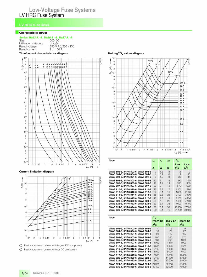
LV HRC fuse links
1/74
LV HRC Fuse SystemLow-Voltage Fuse Systems
Siemens ET B1 T · 2005
■ Characteristic curves
Series 3NA3 8..-6, 3NA6 8..-6, 3NA7 8..-6Size: 000, 00 Utilization category: gL/gGRated voltage: 690 V AC/250 V DCRated current: 2 ... 100 ATime/current characteristics diagram
Current limitation diagram
$ Peak short-circuit current with largest DC component
% Peak short-circuit current without DC component
Melting/I2ts values diagram
��� � � ��
� � � �
�
�
�
� � � �
�� � � �� � �� � � �� � �
�
�
�
� � � �
�
�
�
� � �
�
�
�
� � �
�
�
�
� � �
�
�
�
� � �
�
�
�
� � �
�������
����
����
����
����
����
����
���
��
���
���
�����
����
����
���
�
� � � � � �
� �
� � � � �� � ��
� �
�
�
�
�
�
� � � � � �
���
� �
� � �� � �� � � �� � �� � � �
�������
�
�
�
�
�
� � �
�
� � � � � � �
� � �
� � � �
� � �
� �
� � �
� � � �
� � � �
� � � �
� � � �
� � �
� � � �
� � � �
� � � �
Type In Pv �� I2ts1 ms 4 ms
A W K A2s A2s
3NA3 802-6, 3NA6 802-6, 3NA7 802-6 2 1.3 8 2 23NA3 804-6, 3NA6 804-6, 3NA7 804-6 4 0.9 6 11 133NA3 801-6, 3NA6 801-6, 3NA7 801-6 6 1.3 8 36 44
3NA3 803-6, 3NA6 803-6, 3NA7 803-6 10 1 8 90 1203NA3 805-6, 3NA6 805-6, 3NA7 805-6 16 1.7 11 330 3603NA3 807-6, 3NA6 807-6, 3NA7 807-6 20 2 15 570 690
3NA3 810-6, 3NA6 810-6, 3NA7 810-6 25 2.3 17 1200 13803NA3 812-6, 3NA6 812-6, 3NA7 812-6 32 3.1 19 1600 26003NA3 814-6, 3NA6 814-6, 3NA7 814-6 35 3.6 23 2100 3100
3NA3 817-6, 3NA6 817-6, 3NA7 817-6 40 3.6 18 3200 47003NA3 820-6, 3NA6 820-6, 3NA7 820-6 50 4.9 28 4400 74003NA3 822-6, 3NA6 822-6, 3NA7 822-6 63 5.7 33 7600 10100
3NA3 824-6, 3NA6 824-6, 3NA7 824-6 80 6.7 38 13500 170003NA3 830-6, 3NA6 830-6, 3NA7 830-6 100 9.1 40 21200 30500
Type I2ta230 V AC 400 V AC 690 V AC
A2s A2s A2s
3NA3 802-6, 3NA6 802-6, 3NA7 802-6 4 6 93NA3 804-6, 3NA6 804-6, 3NA7 804-6 18 22 273NA3 801-6, 3NA6 801-6, 3NA7 801-6 80 110 150
3NA3 803-6, 3NA6 803-6, 3NA7 803-6 180 265 3703NA3 805-6, 3NA6 805-6, 3NA7 805-6 580 750 10003NA3 807-6, 3NA6 807-6, 3NA7 807-6 1000 1370 1900
3NA3 810-6, 3NA6 810-6, 3NA7 810-6 1800 2340 33003NA3 812-6, 3NA6 812-6, 3NA7 812-6 3100 4100 58003NA3 814-6, 3NA6 814-6, 3NA7 814-6 4000 5000 7800
3NA3 817-6, 3NA6 817-6, 3NA7 817-6 6000 8600 120003NA3 820-6, 3NA6 820-6, 3NA7 820-6 9100 11200 190003NA3 822-6, 3NA6 822-6, 3NA7 822-6 13600 17000 24000
3NA3 824-6, 3NA6 824-6, 3NA7 824-6 24300 32000 550003NA3 830-6, 3NA6 830-6, 3NA7 830-6 42400 52000 75000
� � � �� � �� � �� � � �� � �� � � �� �� � � � �� ��� �
�
�
�
� �
�
�
�
� �
�
�
�
� �
�
�
�
� �
�
�
�
� �
�
�
�
� �
�������
�
�
�
�
�
�
�
� � �
� ���
� �� ��
� �� ��
� �� ��
� �� �
� �
� � �
� � � �
� � � �
� � � �
� � � �
� � � �
� � � �
� � �
� � � �
� � � �
� � �
� � � � �
� � � � � �
�
��� �
�

LV HRC fuse links
1/75
LV HRC Fuse SystemLow-Voltage Fuse Systems 1
345678910
1213
Siemens ET B1 T · 2005
■ Characteristic curves
Series 3NA3 1..-6, 3NA6 1..-6, 3NA7 1..-6Size: 1Utilization category: gL/gGRated voltage: 690 V AC/440 V DCRated current: 50 ... 200 ATime/current characteristics diagram
Current limitation diagram
$ Peak short-circuit current with largest DC component
% Peak short-circuit current without DC component
Melting/I2ts values diagram
�� � �
� � � �
�
�
�
� � � �
�� � � �� � �� � � �� � �
�
�
�
� � � �
�
�
�
� � �
�
�
�
� � �
�
�
�
� � �
�
�
�
� � �
�
�
�
� � �
�������
� � � ��
� � � � �
� � � � �
� � � � �
� � � � �
� � �
� � � �
� � � �
�
� � � � � �
� �
� � � � �� � ��
� �
� � � � �
� � � � �
�
�
�
�
� � � � �
� � � �
�
� � � � � �
���
� � �
�
� � �� � �� � � �� � �� � � �
� � �
� � � �
�������
�
� � � � �
�
� �
Type In Pv �� I2ts1 ms 4 ms
A W K A2s A2s
3NA3 120-6, 3NA6 120-6, 3NA7 120-6 50 6.7 21 440 74003NA3 122-6, 3NA6 122-6, 3NA7 122-6 63 7.6 22 7600 101003NA3 124-6, 3NA6 124-6, 3NA7 124-6 80 6.7 22 13500 17000
3NA3 130-6, 3NA6 130-6, 3NA7 130-6 100 8.7 28 21200 305003NA3 132-6, 3NA6 132-6, 3NA7 132-6 125 10.5 29 36000 500003NA3 136-6, 3NA6 136-6, 3NA7 136-6 160 13.8 33 58000 85000
3NA3 140-6, 3NA6 140-6, 3NA7 140-6 200 16.6 35 132000 144000
Type I2ta230 V AC 400 V AC 690 V AC
A2s A2s A2s
3NA3 120-6, 3NA6 120-6, 3NA7 120-6 9100 11200 19003NA3 122-6, 3NA6 122-6, 3NA7 122-6 13600 17000 240003NA3 124-6, 3NA6 124-6, 3NA7 124-6 24300 32000 55000
3NA3 130-6, 3NA6 130-6, 3NA7 130-6 42400 52000 750003NA3 132-6, 3NA6 132-6, 3NA7 132-6 69500 82200 1300003NA3 136-6, 3NA6 136-6, 3NA7 136-6 120000 155000 223000
3NA3 140-6, 3NA6 140-6, 3NA7 140-6 211000 240000 360000
� � � �� � �� � �� � � �� � �� � � �� �� � � � �� ��� �
�
�
�
� �
�
�
�
� �
�
�
�
� �
�
�
�
� �
�
�
�
� �
�
�
�
� �
�������
�
�
�
�
�
�
�
� ���
� �� ��
� �� ��
� �� ��
� �� �
� � � � �
� � � � �
� � �
� � � �
� � � �
� � � � �
� � � � �
� � � � � �
�
��� �
�

LV HRC fuse links
1/76
LV HRC Fuse SystemLow-Voltage Fuse Systems
Siemens ET B1 T · 2005
■ Characteristic curves
Series 3NA3 2..-6, 3NA6 2..-6, 3NA7 2..-6Size: 2Utilization category: gL/gGRated voltage: 690 V AC/440 V DCRated current: 80 ... 315 ATime/current characteristics diagram
Current limitation diagram
$ Peak short-circuit current with largest DC component
% Peak short-circuit current without DC component
Melting/I2ts values diagram
�� � �
� � � �
�
�
�
� � � �
�� � � �� � �� � � �� � �
�
�
�
� � � �
�
�
�
� � �
�
�
�
� � �
�
�
�
� � �
�
�
�
� � �
�
�
�
� � �
�������
� � � ��
� � � � �
� � � �
� � � � �
� � � � �
� � � � �
� � � � �
� � �
� � � � � � � �
�
� � � � � �
� �
� � � � �� � ��
� �
�
�
�
� � � � �
� � � � �
�
�
�
�
� � � � �
�
� � � � � �
���
� � �
� � �
� � �� � �� � � �� � �� � � �
� � �
�������
� � � � �
� � � �
� � � � �
� �
� � � � �
Type In Pv �� I2ts1 ms 4 ms
A W K A2s A2s
3NA3 224-6, 3NA6 224-6, 3NA7 224-6 80 6.6 22 13500 170003NA3 230-6, 3NA6 230-6, 3NA7 230-6 100 8.5 26 21200 305003NA3 232-6, 3NA6 232-6, 3NA7 232-6 125 9.8 29 36000 50000
3NA3 236-6, 3NA6 236-6, 3NA7 236-6 160 13.3 31 58000 850003NA3 240-6, 3NA6 240-6, 3NA7 240-6 200 16.1 33 132000 1440003NA3 242-6, 3NA6 242-6, 3NA7 242-6 224 19.9 38 125000 162000
3NA3 244-6, 3NA6 244-6, 3NA7 244-6 250 23 44 180000 2150003NA3 250-6, 3NA6 250-6, 3NA7 250-6 300 25.6 38 300000 3800003NA3 252-6, 3NA6 252-6, 3NA7 252-6 315 28.2 42 300000 380000
Type I2ta230 V AC 400 V AC 690 V AC
A2s A2s A2s
3NA3 224-6, 3NA6 224-6, 3NA7 224-6 24300 32000 550003NA3 230-6, 3NA6 230-6, 3NA7 230-6 42400 52000 750003NA3 232-6, 3NA6 232-6, 3NA7 232-6 69500 82200 130000
3NA3 236-6, 3NA6 236-6, 3NA7 236-6 120000 155000 2230003NA3 240-6, 3NA6 240-6, 3NA7 240-6 211000 240000 3600003NA3 242-6, 3NA6 242-6, 3NA7 242-6 300000 300000 450000
3NA3 244-6, 3NA6 244-6, 3NA7 244-6 453000 350000 5250003NA3 250-6, 3NA6 250-6, 3NA7 250-6 480000 625000 9400003NA3 252-6, 3NA6 252-6, 3NA7 252-6 480000 625000 940000
� � � �� � �� � �� � � �� � �� � � �� �� � � � �� ��� �
�
�
�
� �
�
�
�
� �
�
�
�
� �
�
�
�
� �
�
�
�
� �
�
�
�
� �
�������
�
�
�
�
�
�
�
� � � � �
� � � � �
� � �
� � � � �
� � � � �
� ���
� �� ��
� �� ��
� �� ��
� �� �
� � � �
� � � � �
� � � � � � � �
� � � � � �
�
��� �
�

LV HRC fuse links
1/77
LV HRC Fuse SystemLow-Voltage Fuse Systems 1
345678910
1213
Siemens ET B1 T · 2005
■ Characteristic curves
Series 3NA3 3..-6Size: 3Utilization category: gL/gGRated voltage: 690 V AC/440 V DCRated current: 250 ... 500 ATime/current characteristics diagram
Current limitation diagram
$ Peak short-circuit current with largest DC component
% Peak short-circuit current without DC component
Melting/I2ts values diagram
�� � �
� � � �
�
�
�
� � � �
�� � � �� � �� � � �� � �
�
�
�
� � � �
�
�
�
� � �
�
�
�
� � �
�
�
�
� � �
�
�
�
� � �
�
�
�
� � �
�������
� � � ��
� � � �
� � � �
� � � � �
� � � � �
� � � � �
� � � � �
�
� � � � � �
� �
� �
� �
�
�
�
�
�
� � � � � �
���
� � �
� ��� � �� � �� � � �
�������
� � � � �
� � � � �
� �
� � � � �
� � � �
� � � �
� � � � �
Type In Pv �� I2ts1 ms 4 ms
A W K A2s A2s
3NA3 344-6 250 23 44 180000 2150003NA3 352-6 315 28.2 42 300000 3800003NA3 354-6 355 32.5 40 380000 470000
3NA3 360-6 400 33.2 42 540000 6750003NA3 362-6 425 35.3 44 625000 7650003NA3 365-6 500 43.5 52 810000 1000000
Type I2ta230 V AC 400 V AC 690 V AC
A2s A2s A2s
3NA3 344-6 453000 350000 5250003NA3 352-6 480000 625000 9400003NA3 354-6 585000 760000 1150000
3NA3 360-6 847000 1100000 16500003NA3 362-6 925000 1200000 18000003NA3 365-6 1300000 1700000 2500000
� � � �� � �� � �� � � �� � �� � � �� �� � � � �� ��� �
�
�
�
� �
�
�
�
� �
�
�
�
� �
�
�
�
� �
�
�
�
� �
�
�
�
� �
�������
�
�
�
�
�
�
�
� ���
� �� ��
� �� ��
� �� ��
� �� �
� � � � �
� � � � �
� � � � �
� � � �
� � � � �
� � � � � �
�
��� �
� � � � �

LV HRC fuse links
1/78
LV HRC Fuse SystemLow-Voltage Fuse Systems
Siemens ET B1 T · 2005
■ Characteristic curves
Series 3ND1 8Size: 000, 00Utilization category: aMRated voltage: 500 V ACRated current: 6 ... 160 ATime/current characteristics diagram
Current limitation diagram
$ Peak short-circuit current with largest DC component
% Peak short-circuit current without DC component
Melting/I2ts values diagram
�� � �
� � � �
�
�
�
� � � �
�� � � �� � �� � � �� � �
�
�
�
� � � �
�
�
�
� � �
�
�
�
� � �
�
�
�
� � �
�
�
�
� � �
�������
� � � ��
���
����
����
���
�����
�����
�����
����
���
����
����
����
����
����
�
� � � � � �
� �
� � � � �� � ��
� �
�
�
�
� � � � �
�
�
�
�
� � �
� � � �
� � � �
� � � �
� � � � �
� � � �
� � � �
� � � �
� � � �
� � �
�
� � � � � �
���
� � �
�
� � �� � �� � � �� � �� � � �
� � �
� � � �
�������
� � � � �
� �
Type In Pv �� I2ts1 ms 4 ms
A W K A2s A2s
3ND1 801 6 0.8 7 32 553ND1 803 10 0.5 5 150 2603ND1 805 16 0.8 7 570 800
3ND1 807 20 1 8 830 12003ND1 810 25 1.2 9 1400 20003ND1 812 32 1.5 10 2300 3300
3ND1 814 35 1.8 11 2600 38003ND1 817 40 2 12 3700 55003ND1 820 50 2.4 14 5800 8400
3ND1 822 63 3.3 17 9300 130003ND1 824 80 4.5 20 15000 210003ND1 830 100 4.9 18 26000 37000
3ND1 832 125 6.3 22 41000 600003ND1 836 160 9.3 31 64000 92000
Type I2ta230 V AC 400 V AC 500 V AC
A2s A2s A2s
3ND1 801 60 75 1103ND1 803 280 320 4303ND1 805 1000 1300 1600
3ND1 807 1300 1600 22003ND1 810 2200 2800 33003ND1 812 3800 4500 5400
3ND1 814 4200 5100 63003ND1 817 5700 7200 93003ND1 820 5200 10500 12500
3ND1 822 15000 16500 210003ND1 824 21500 27000 340003ND1 830 44000 56000 76000
3ND1 832 76000 98000 1350003ND1 836 105000 130000 170000
� � � �� � �� � �� � � �� � �� � � �� �� � � � �� ��� �
�
�
�
� �
�
�
�
� �
�
�
�
� �
�
�
�
� �
�
�
�
� �
�
�
�
� �
�������
�
�
�
�
�
�
�
� ���
� �� ��
� �� ��
� �� ��
� � � �
� � �
� � � �
� � � �
� � � �
� � � �
� � � �
� � �
� � � �
� � � �
� � �
� � � � �
� � � � �
� � � � �
� � � � � �
�
��� �
�
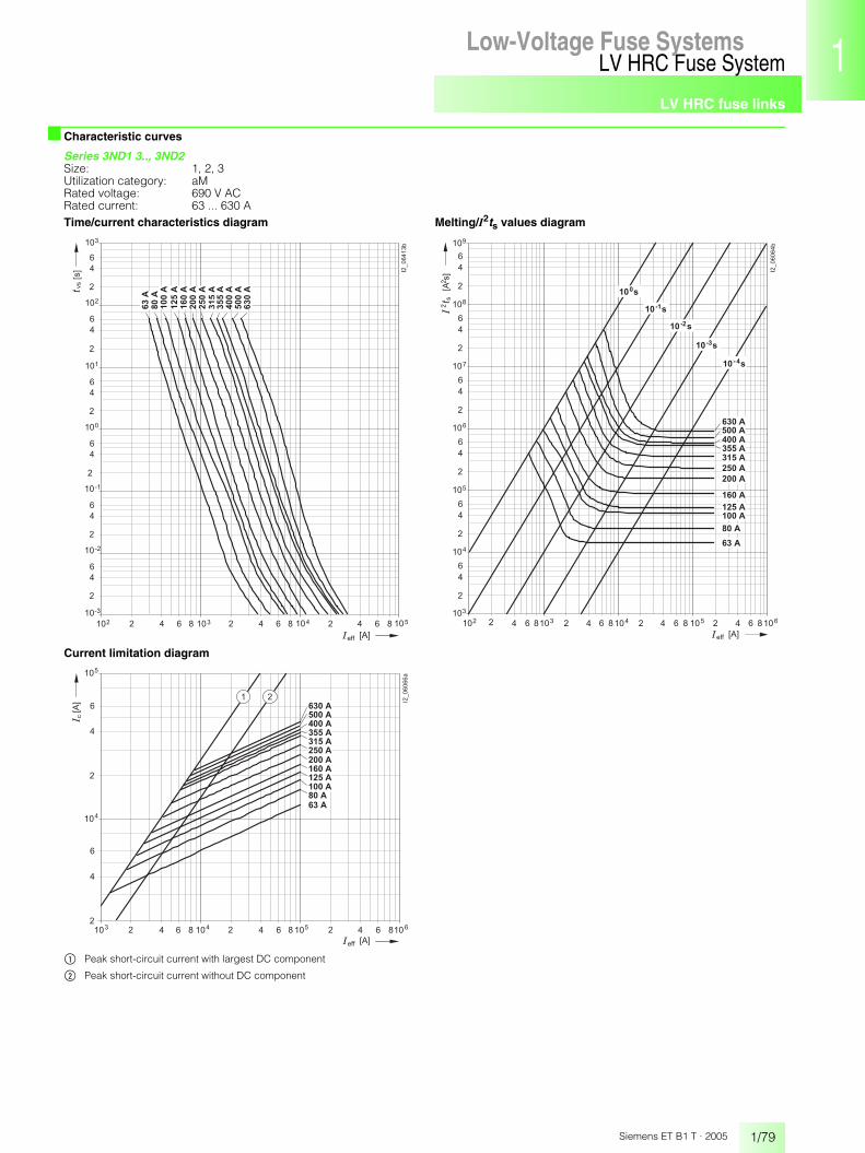
LV HRC fuse links
1/79
LV HRC Fuse SystemLow-Voltage Fuse Systems 1
345678910
1213
Siemens ET B1 T · 2005
■ Characteristic curves
Series 3ND1 3.., 3ND2Size: 1, 2, 3Utilization category: aMRated voltage: 690 V ACRated current: 63 ... 630 ATime/current characteristics diagram
Current limitation diagram
$ Peak short-circuit current with largest DC component
% Peak short-circuit current without DC component
Melting/I2ts values diagram
�� � �
� � � �
�
�
�
� � � �
�� � � �� � �� � � �� � �
�
�
�
� � � �
�
�
�
� � �
�
�
�
� � �
�
�
�
� � �
�
�
�
� � �
�������
� � � ��
���
�����
�����
�����
����
�����
�����
�����
�����
����
�����
�����
�
� � � � � �
� �
� � � � �� � ���
�
�
�
�
�
� � � � � �
���
� � �
� � �� � �� � � �� � �� �
�������
�
� � �
� � � � �
� � � � �
� � � � �
� � �
� � � � �
� � � �
� � � � �
� � � � �
� � � � �
� � � � �
� � � � �
� � � �
� �
� � � �� � �� � �� � � �� � �� � � �� �� � � � �� ��� �
�
�
�
� �
�
�
�
� �
�
�
�
� �
�
�
�
� �
�
�
�
� �
�
�
�
� �
�������
�
�
�
�
�
�
�
� � � �
� � �
� � � � �
� � � � �
� � � � �
� � � � �
� � � � �
� � � � �
� � � �
� � � � �
� � � � �
� � � � � �
�
��� �
�
� ���
� �� ��
� �� ��
� �� ��
� �� �
� � � � �

LV HRC fuse links
1/80
LV HRC Fuse SystemLow-Voltage Fuse Systems
Siemens ET B1 T · 2005
■ Characteristic curves
Series 3ND1 3.., 3ND2Size: 1, 2, 3Utilization category: aMRated voltage: 690 V ACRated current: 63 ... 630 A
Type In Pv �� I2ts I2ta1 ms 4 ms 230 V AC 400 V AC 690 V AC
A W K A2s A2s A2s A2s A2s
3ND2 122 63 4 12.2 14000 17700 19300 25600 420003ND2 124 80 4.9 13 24200 30800 36500 48000 80000
3ND2 130 100 5.8 15 45600 59000 65000 85000 1400003ND2 132 125 8.1 16.5 57000 74300 73000 97000 1600003ND2 136 160 11.4 18 90000 114000 107000 142000 235000
3ND2 140 200 14.1 19.5 150000 198000 172000 228000 3750003ND2 144 250 18 22 250000 313000 260000 340000 565000
3ND2 232 125 8.1 16.5 57000 74300 73000 97000 1600003ND2 236 160 11.4 18 90000 114000 107000 142000 235000
3ND2 240 200 14.1 19.5 150000 198000 172000 228000 3750003ND2 244 250 18 22 250000 313000 260000 340000 5650003ND2 252 315 22.6 30 370000 450000 460000 610000 1000000
3ND2 254 355 24.7 29 540000 643000 645000 855000 14000003ND2 260 400 30.8 35 615000 750000 688000 910000 1500000
3ND2 352 315 22.6 30 370000 450000 460000 610000 10000003ND2 354 355 24.7 29 540000 643000 645000 855000 14000003ND2 360 400 30.8 26 615000 750000 688000 910000 1500000
3ND1 365 500 47 40 730000 933000 876000 1095000 18250003ND1 372 630 50 43 920000 1375000 1300000 1800000 2600000

LV HRC fuse links
1/81
LV HRC Fuse SystemLow-Voltage Fuse Systems 1
345678910
1213
Siemens ET B1 T · 2005
■ Dimensional drawings
LV HRC fuse links
Size Utilization category
In Un Type Dimensions
A V w h1 h2 d1 d2
000 gL/gG 2 ... 100 500 AC/250 DC 3NA3 8.. 21 54 80 45 82 ... 35 690 AC/250 DC 3NA3 8..-62 ... 100 500 AC/250 DC 3NA6 8..
10 ... 100 400 AC 3NA6 8..-42 ... 35 690 AC/250 DC 3NA6 8..-6
10 ... 100 500 AC/250 DC 3NA7 8..2 ... 35 690 AC/250 DC 3NA7 8..-6
aM 6 ... 80 500 AC 3ND1 8..
00 gL/gG 35 ... 160 500 AC/250 DC 3NA3 8.. 30 54 80 45 1440 ... 100 690 AC/250 DC 3NA3 8..-680 ... 160 500 AC/250 DC 3NA6 8..80 ... 160 400 AC 3NA6 8..-440 ... 100 690 AC/250 DC 3NA6 8..-680 ... 160 500 AC/250 DC 3NA7 8..40 ... 100 690 AC/250 DC 3NA7 8..-6
aM 100 ... 160 500 AC 3ND1 8..
0 gL/gG 6 ... 160 500 AC/440 DC 3NA3 0.. 30 67 126 45 14
1 gL/gG 16 ... 160 500 AC/440 DC 3NA3 1.. 30 75 137 50 1550 ... 160 690 AC/440 DC 3NA3 1..-616 ... 160 500 AC/440 DC 3NA6 1..35 ... 160 400 AC 3NA6 1..-450 ... 160 690 AC/440 DC 3NA6 1..-616 ... 160 500 AC/440 DC 3NA7 1..50 ... 160 690 AC/440 DC 3NA7 1..-6
aM 63 ... 100 690 AC 3ND2 1..
gL/gG 200 ... 250 500 AC/440 DC 3NA3 1.. 47 75 137 51 9200 690 AC/440 DC 3NA3 1..-6200 ... 250 500 AC/440 DC 3NA6 1..200 ... 250 400 AC 3NA6 1..-4200 690 AC/440 DC 3NA6 1..-6200 ... 250 500 AC/440 DC 3NA7 1..200 690 AC/440 DC 3NA7 1..-6
aM 125 ... 250 690 AC 3ND2 1..
2 gL/gG 35 ... 250 500 AC/440 DC 3NA3 2.. 47 75 151 58 1080 ... 200 690 AC/440 DC 3NA3 2..-635 ... 250 500 AC/440 DC 3NA6 2..50 ... 300 400 AC 3NA6 2..-480 ... 200 690 AC/440 DC 3NA6 2..-635 ... 300 500 AC/440 DC 3NA7 2..80 ... 200 690 AC/440 DC 3NA7 2..-6
aM 125 ... 250 690 AC 3ND2 2..
gL/gG 300 ... 400 500 AC/440 DC 3NA3 2.. 58 74 151 59 13224 ... 315 690 AC/440 DC 3NA3 2..-6300 ... 400 500 AC/440 DC 3NA6 2..315 ... 400 400 AC 3NA6 2..-4224 ... 315 690 AC/440 DC 3NA6 2..-6315 ... 400 500 AC/440 DC 3NA7 2..224 ... 315 690 AC/440 DC 3NA7 2..-6
aM 315 ... 400 690 AC 3ND2 2..
3 gL/gG 200 ... 400 500 AC/440 DC 3NA3 3.. 58 74 151 71 13250, 315 690 AC/440 DC 3NA3 3..-6
aM 315 ... 400 690 AC 3ND2 3..
gL/gG 425 ... 630 500 AC/440 DC 3NA3 3.. 71 74 151 70 13355 ... 500 690 AC/440 DC 3NA3 3..-6
aM 500, 630 690 AC 3ND1 3..
4 gL/gG 630 ... 1250 500 AC/440 DC 3NA3 4.. see adjacent drawing
4 A gL/gG 500 ... 1250 500 AC/440 DC 3NA3 6.. 102 97 201 95 20
� � � � � �
�
� �
��
��
� �
202
I2_11335
65 55
9010
2Sizes 000 to 3 and 4a
Size 4 (IEC design)

LV HRC SITOR fuse links
1/82
LV HRC Fuse SystemLow-Voltage Fuse Systems
Siemens ET B1 T · 2005
■ Application
PropertiesSITOR fuse links protect converter equipment against short-circuits. The power semiconductors used in these devices (diodes, thyristors, GTOs and others) require high-speed elements for protection due to their low thermal capacity. SITOR fuse links (high-speed fuse links for semiconductor protection).The following types of short-circuit faults can occur:• Internal short circuit:
A faulty semiconductor device causes a short circuit within the chassis converter
• External short circuit:A fault in the load causes a short circuit on the output side of the chassis converter
• Shoot-throughs:In the event of a failure of the chassis converter control system during inverter operation (commutation failure), the converter con-nection forms a short-circuit type connection between the DC and AC power supply system.
Fuse links can be arranged in a number of ways within the converter connection. A distinction is made between phase fuses in three-phase current incoming feeders and, if applicable, DC fuses and arm fuses in the arms of the converter connections (see adjacent graphs). In the case of center tap connections, fuse links can only be arranged as phase fuses in three-phase current incoming feeders.When using SITOR fuse links of utilization category aR, the overload protection of converter equipment, up to approx. 3.5 times the rated current of the fuse link, is taken from conventional protective devices (for example, thermal-delayed overload relays) or, in the case of controlled power converters, from the current limiter (exception: general purpose fuses).As semiconductor protection, SITOR fuse links of the series 3NE1 ...-0 with utilization category gS are also suitable for the overload and short-circuit protection of cables, lines and power rails. All other dual-function fuses of the SITOR series have a gR charac-teristic. Overload protection is ensured as long as the rated current of the SITOR fuse links of the series 3NE1 ..-0 is selected as In � Iz (DIN VDE 0100 Part 430).The rules of DIN VDE 0100 Part 430 must be applied when rating short-circuit protection for cables, lines and power rails.
Arrangement options
I2_1
0893
I2_1
0894
( ) ( )
Six-pulse bridge converter B6 with phase fuses
Six-pulse bridge converter B6 with phase fuses and DC fuse (reversible connection)
I2_1
0895
I2_1
0896
Six-pulse bridge converter B6 with phase fuses and DC fuse (switching for converter)
Six-pulse bridge converter B6 with arm fuses
I2_1
0897
( ) ( )
Six-pulse bridge converter B6 with arm fuses (reversible connection)
I2_1
0898
Three-phase bidirectional connection W3 with phase fuses with arm fuses
Low-Voltage Fuse Systems

LV HRC SITOR fuse links
1/83
LV HRC Fuse SystemLow-Voltage Fuse Systems 1
345678910
1213
Siemens ET B1 T · 2005
■ Technical specifications
1) Cooling air speed 1 m/s. In case of natural air cooling, reduction of 5 %.
Type 3NC2 423 3NC2 423-3
3NC2 425 3NC2 425-3
3NC2 427 3NC2 427-3
3NC2 428 3NC2 428-3
3NC2 431 3NC2 431-3
3NC2 432 3NC2 432-3
Utilization category (IEC 60269) gR aR
Rated voltage Un V AC 500
Rated current In A 150 1) 200 1) 250 1) 300 1) 350 1) 400 1)
Melting I2t value I2ts (tvs = 1 ms) A2s 7000 13600 21000 28000 53000 83000
Breaking I2t value I2tA at Un A2s 33000 64000 99000 132000 249000 390000
Temperature rise at In (body center) K 26 25 30 40 35 30
Power dissipation at In W 35 40 50 65 60 50
Varying load factor WL 0.85
Weight approx. kg 0.95
Accessories
Fuse base, 1-pole 3NH3 430
Fuse puller 3NX1 011
Fuse switch disconnectors 3NP54
Switch disconnector with fuses 3KL61 30-1.B0
Type 3NE8 714-1 3NE8 715-1 3NE8 701-1 3NE8 702-1 3NE8 717-1 3NE8 718-1
Utilization category (IEC 60269) gR aR
Rated voltage Un V 690 AC/700 DC
Rated current In A 20 25 32 40 50 63
Melting I2t value I2ts (tvs = 1 ms) A2s 12 19 40 69 115 215
Breaking I2t value I2tA at Un A2s 83 140 285 490 815 1550
Temperature rise at In (body center) K 40 45 55 60 70
Power dissipation at In W 7 9 10 12 15 16
Varying load factor WL
Approval according to UL 248-13
Weight approx. kg 0.13
Type 3NE8 720-1 3NE8 721-1 3NE8 722-1 3NE8 724-1 3NE8 725-1 3NE8 727-1 3NE8 731-1
Utilization category (IEC 60269) aR
Rated voltage Un V 690 AC/700 DC
Rated current In A 80 100 125 160 200 250 315
Melting I2t value I2ts (tvs = 1 ms) A2s 380 695 1250 2350 4200 7750 12000
Breaking I2t value I2tA at Un A2s 2700 4950 9100 17000 30000 55000 85500
Temperature rise at In (body center) K 80 75 80 100 120 125 150
Power dissipation at In W 18 19 23 31 36 42 54
Varying load factor WL 0.9 0.95 0.9 0.85
Approval according to UL 248-13
Weight approx. kg 0.13
Type 3NC8 423 3NC8 423-3
3NC8 425 3NC8 425-3
3NC8 427 3NC8 427-3
3NC8 431 3NC8 431-3
3NC8 434 3NC8 434-3
3NC8 444-3
Utilization category (IEC 60269) gR aR
Rated voltage Un V AC 660 600
Rated current In A 150 1) 200 1) 250 350 1) 500 1) 10001)
Melting I2t value I2ts (tvs = 1 ms) A2s 1100 2400 4400 11000 28000 400000
Breaking I2t value I2tA at Un A2s 17600 38400 70400 176000 448000 2480000
Temperature rise at In (body center) K 33 46 95 65 75 110
Power dissipation at In W 40 55 72 95 130 140
Varying load factor WL 0.85 0.9
Weight approx. kg 0.95
Accessories
Fuse base, 1-pole 3NH3 430 –
Fuse puller 3NX1 011
Fuse switch disconnectors 3NP54 –
Switch disconnector with fuses 3KL61 30-1AB0 –

LV HRC SITOR fuse links
1/84
LV HRC Fuse SystemLow-Voltage Fuse Systems
Siemens ET B1 T · 2005
■ Technical specifications
1) Temperature rise and power dissipation for operation in LV HRC fuse base.
Type 3NE1 813-0 3NE1 814-0 3NE1 815-0 3NE1 803-0 3NE1 802-0 3NE1 817-0 3NE1 818-0 3NE1 820-0
Utilization category (IEC 60269) gR/gS
Rated voltage Un V AC 690
Rated current In A 16 20 25 35 40 50 63 80
Melting I2t value I2ts (tvs = 1 ms) A2s 18 41 74 166 295 461 903 1843
Breaking I2t value I2tA at Un A2s 200 430 780 1700 3000 4400 9000 18000
Temperature rise at In (body center) 1)
K 25 30 35 30 35 40
Power dissipation at In 1) W 3.0 3.5 4.0 5.0 6.0 7.0 8.0
Varying load factor WL 1.0
Approval according to UL 248-13
Weight approx. kg 0.13
Accessories
Fuse base, 1-pole 3NH3 0303-pole 3NH4 030
Fuse puller 3NX1 011
Fuse switch disconnectors 3NP40/3NP50
Switch disconnector with fuses 3KL50 30-1.B00 3KM50 30-1.B00
3KL52 30-1.B00 3KM52 30-1.B00
Type 3NE1 021-0 3NE1 022-0 3NE1 224-0 3NE1 225-0 3NE1 227-0 3NE1 230-0
Utilization category (IEC 60269) gR/gS
Rated voltage Un V AC 690
Rated current In A 100 125 160 200 250 315
Melting I2t value I2ts (tvs = 1 ms) A2s 3100 6000 7400 14500 29500 46100
Breaking I2t value I2tA at Un A2s 33000 63000 60000 100000 200000 310000
Temperature rise at In (body center) 1)
K 36 40 60 65 75 80
Power dissipation at In 1) W 10 11 24 27 30 38
Varying load factor WL 1.0
Approval according to UL 248-13
Weight approx. kg 0.20 0.55
Accessories
Fuse base, 1-pole 3NH3 030 3NH3 230 3NH3 330
3-pole 3NH4 030 3NH4 230 3NH4 330
Fuse puller 3NX1 011
Fuse switch disconnectors 3NP403NP50
3NP423NP52
3NP53
Switch disconnector with fuses 3KL52 30-1.B00 3KM52 30-1.B00
3KL55 30-1.B00 3KM55 30-1.B00
3KL57 30-1.B00 3KM57 30-1.B00
Type 3NE1 331-0 3NE1 332-0 3NE1 333-0 3NE1 334-0 3NE1 435-0 3NE1 436-0 3NE1 437-0 3NE1 438-0
Utilization category (IEC 60269) gR/gS
Rated voltage Un V AC 690
Rated current In A 350 400 450 500 560 630 710 800
Melting I2t value I2ts (tvs = 1 ms) A2s 58000 84000 104000 149000 215000 293000 437000 723000
Breaking I2t value I2tA at Un A2s 430000 590000 750000 950000 1700000 2350000 3400000 5000000
Temperature rise at In (body center) 1)
K 75 85 90 65 70 68 70
Power dissipation at In 1) W 42 45 53 56 50 55 60 59
Varying load factor WL 1.0
Approval according to UL 248-13
Weight approx. kg 0.7 0.95
Accessories
Fuse base, 1-pole 3NH3 330 3NH3 430
Fuse puller 3NX1 011
Fuse switch disconnectors 3NP53 3NP54
Switch disconnector with fuses 3KL57 30-1.B00 3KM57 30-1.B00
3KL61 30-1AB0 3KL62

LV HRC SITOR fuse links
1/85
LV HRC Fuse SystemLow-Voltage Fuse Systems 1
345678910
1213
Siemens ET B1 T · 2005
■ Technical specifications
1) Temperature rise and power dissipation for operation in LV HRC fuse base.
Type 3NE1 437-1 3NE1 438-1
Utilization category (IEC 60269) gR
Rated voltage Un V AC 600
Rated current In A 710 800
Melting I2t value I2ts (tvs = 1 ms) A2s 321000 437000
Breaking I2t value I2tA at Un A2s 2460000 3350000
Temperature rise at In (body center) 1) K 85 95
Power dissipation at In 1) W 65 72
Varying load factor WL 1.0
Approval according to UL 248-13
Weight approx. kg 0.95
Accessories
Fuse base, 1-pole 3NH3 430
Fuse puller 3NX1 011
Fuse switch disconnectors 3NP54
Switch disconnector with fuses 3KL62 30
Type 3NE1 022-2 3NE1 224-2 3NE1 225-2 3NE1 227-2 3NE1 230-2 3NE1 331-2 3NE1 333-2 3NE1 334-2
Utilization category (IEC 60269) gR
Rated voltage Un V AC 690
Rated current In A 125 160 200 250 315 350 450 500
Melting I2t value I2ts (tvs = 1 ms) A2s 3115 2650 5645 11520 22580 29500 46100 66400
Breaking I2t value I2tA at Un A2s 23000 15840 44000 68800 135500 177000 276000 398000
Temperature rise at In (body center) 1) K 55 70 62 70 75 82 100
Power dissipation at In 1) W 13.5 30 28 35 42 44 62 65
Varying load factor WL 1.0
Approval according to UL 248-13
Weight approx. kg 0.2 0.55 0.7
Accessories
Fuse base, 1-pole 3NH3 030 3NH3 230 3NH3 340
Fuse puller 3NX1 011
Fuse switch disconnectors 3NP50 3NP52 3NP53 3NP54
Switch disconnector with fuses 3KL52 3KL55 3KL57 3KL61
Type 3NE1 435-2 3NE1 436-2 3NE1 447-2 3NE1 437-2 3NE1 438-2 3NE1 448-2
Utilization category (IEC 60269) gR
Rated voltage Un V AC 690
Rated current In A 560 630 670 710 800 850
Melting I2t value I2ts (tvs = 1 ms) A2s 130000 203000 240000 265000 361000 520000
Breaking I2t value I2tA at Un A2s 845000 1320000 1557000 1725000 2348000 3810000
Temperature rise at In (body center) 1) K 80 82 90 95
Power dissipation at In 1) W 60 62 65 72 82 76
Varying load factor WL 1.0
Approval according to UL 248-13
Weight approx. kg 1.0
Accessories
Fuse base, 1-pole 3NH3 340
Fuse puller 3NX1 011
Fuse switch disconnectors 3NP54 3NP54
Switch disconnector with fuses 3KL61 3KL62

LV HRC SITOR fuse links
1/86
LV HRC Fuse SystemLow-Voltage Fuse Systems
Siemens ET B1 T · 2005
■ Technical specifications
Type 3NE8 015-1 3NE8 003-1 3NE8 017-1 3NE8 018-1 3NE8 020-1 3NE8 021-1 3NE8 022-1 3NE8 024-1
Utilization category (IEC 60269) gR aR
Rated voltage Un V AC 690
Rated current In A 25 35 50 63 80 100 125 160
Melting I2t value I2ts (tvs = 1 ms) A2s 30 70 120 260 450 850 1400 2800
Breaking I2t value I2tA at Un A2s 180 400 700 1400 2400 4200 6500 1300
Temperature rise at In (body center) K 35 45 65 70 80 90 110 130
Power dissipation at In W 7 9 14 16 19 22 28 38
Varying load factor WL 0.95
Approval according to UL 248-13
Weight approx. kg 0.20
Accessories
Fuse base, 1-pole 3NH3 0303-pole 3NH4 030
Fuse puller 3NX1 011
Fuse switch disconnectors 3NP403NP50
Switch disconnector with fuses 3KL50 30-1.B00 3KM50 30-1.B00
3KL52 30-1.B00 3KM52 30-1.B00
Type 3NE4 327-0B 3NE4 330-0B 3NE4 333-0B 3NE4 334-0B 3NE4 337
Utilization category (IEC 60269) aR
Rated voltage Un V AC 800
Rated current In A 250 315 450 500 710
Melting I2t value I2ts (tvs = 1 ms) A2s 3600 7400 29400 42500 142000
Breaking I2t value I2tA at Un A2s 29700 60700 191000 276000 923000
Temperature rise at In (body center) K 175 170 190 195 170
Power dissipation at In W 105 120 140 155
Varying load factor WL 0.85 0.95
Weight approx. kg 0.7
Accessories
Fuse base, 1-pole 3NH3 330 3NH3 430
Fuse puller 3NX1 011
Fuse switch disconnectors 3NP53 3NP54
Switch disconnector with fuses 3KL57 30-1.B00 3KM57 30-1.B00
3KL61 3KL62
Type 3NE4 101 3NE4 102 3NE4 117 3NE4 118 3NE4 120 3NE4 121 3NE4 122 3NE4 124
Utilization category (IEC 60269) gR aR
Rated voltage Un V AC 1000
Rated current In A 32 40 50 63 80 100 125 160
Melting I2t value I2ts (tvs = 1 ms) A2s 40 75 120 230 450 900 1800 3600
Breaking I2t value I2tA at Un A2s 280 500 800 1500 3000 6000 14000 29000
Temperature rise at In (body center) K 45 50 65 78 82 85 100 120
Power dissipation at In W 12 13 16 20 22 24 30 35
Varying load factor WL 0.9
Approval according to UL 248-13
Weight approx. kg 0.27
Accessories
Fuse base, 1-pole 3NH3 1203-pole 3NH4 230
Fuse puller 3NX1 011
Fuse switch disconnectors 3NP42, 3NP52
Switch disconnector with fuses 3KL55 30-1.B00 3KM55 30-1.B00

LV HRC SITOR fuse links
1/87
LV HRC Fuse SystemLow-Voltage Fuse Systems 1
345678910
1213
Siemens ET B1 T · 2005
■ Technical specifications
Type 3NE3 221 3NE3 222 3NE3 224 3NE3 225 3NE3 227
Utilization category (IEC 60269) aR
Rated voltage Un V AC 1000
Rated current In A 100 125 160 200 250
Melting I2t value I2ts (tvs = 1 ms) A2s 665 1040 1850 4150 6650
Breaking I2t value I2tA at Un A2s 4800 7200 13000 30000 48000
Temperature rise at In (body center) K 65 70 90 80 90
Power dissipation at In W 28 36 42 50
Varying load factor WL 0.95 1.0
Approval according to UL 248-13
Weight approx. kg 0.55
Accessories
Fuse base, 1-pole 3NH3 2303-pole 3NH4 230
Fuse puller 3NX1 011
Fuse switch disconnectors 3NP42, 3NP52
Switch disconnector with fuses 3KL55 30-1.B00 3KM55 30-1.B00
Type 3NE3 230-0B 3NE3 231 3NE3 232-0B 3NE3 233
Utilization category (IEC 60269) aR
Rated voltage Un V AC 1000
Rated current In A 315 350 400 450
Melting I2t value I2ts (tvs = 1 ms) A2s 13400 16600 22600 29500
Breaking I2t value I2tA at Un A2s 80000 100000 135000 175000
Temperature rise at In (body center) K 100 120 140 130
Power dissipation at In W 65 75 85 95
Varying load factor WL 0.95 0.9
Approval according to UL 248-13
Weight approx. kg 0.55
Accessories
Fuse base, 1-pole 3NH3 330
Fuse puller 3NX1 011
Fuse switch disconnectors 3NP53
Switch disconnector with fuses 3KL57 30-1.B00 3KM57 30-1.B00
Type 3NE3 332-0B
3NE3 333 3NE3 334-0B
3NE3 335 3NE3 336 3NE3 337-8 3NE3 338-8 3NE3 340-8
Utilization category (IEC 60269) aR
Rated voltage Un V AC 1000 900 800 690
Rated current In A 400 450 500 560 630 710 800 900
Melting I2t value I2ts (tvs = 1 ms) A2s 22600 29500 46100 66400 104000 149000 184000 223000
Breaking I2t value I2tA at Un A2s 135000 175000 260000 360000 600000 800000 850000 1300000
Temperature rise at In (body center) K 120 125 115 120 110 125 140 160
Power dissipation at In W 85 90 95 100 105 130 165
Varying load factor WL 0.7 0.95
Approval according to UL 248-13
Weight approx. kg 0.7
Accessories
Fuse base, 1-pole 3NH3 430
Fuse puller 3NX1 011
Fuse switch disconnectors 3NP54
Switch disconnector with fuses 3KL61 30-1AB0 3KL62

LV HRC SITOR fuse links
1/88
LV HRC Fuse SystemLow-Voltage Fuse Systems
Siemens ET B1 T · 2005
■ Technical specifications
1) Gauge 140 mm, M12 screw connection.
2) M12 screw connection
Type 3NE3 421 3NE3 626 3NE3 430 3NE3 432 3NE3 635 3NE3 635-6
3NE3 434 3NE3 636 3NE3 637 3NE3 637-1 1)
Utilization category (IEC 60269) aR
Rated voltage Un V AC 1000
Rated current In A 100 224 315 400 450 500 630 710
Melting I2t value I2ts (tvs = 1 ms) A2s 1800 7200 29000 48500 65000 116000 170000 260000
Breaking I2t value I2tA at Un A2s 13500 54000 218000 364000 488000 870000 1280000 1950000
Temperature rise at In (body center) K 45 140 120 130 150 120 136 170
Power dissipation at In W 25 85 80 110 95 132 145
Varying load factor WL 1.0
Weight approx. kg 1.15
Type 3NE5 424 3NE5 426 3NE5 430 3NE5 431 3NE5 433 3NE5 433-1
Utilization category (IEC 60269) aR
Rated voltage Un V AC 1500
Rated current In A 160 224 315 350 450
Melting I2t value I2ts (tvs = 1 ms) A2s 7200 18400 41500 57000 116000
Breaking I2t value I2tA at Un A2s 54000 138000 311000 428000 870000
Temperature rise at In (body center) K 75 100 125 150 150
Power dissipation at In W 56 80 115 135 145
Varying load factor WL 1.0 0.95
Weight approx. kg 1.95
Type 3NE5 627 3NE5 633 3NE5 643
Utilization category (IEC 60269) aR
Rated voltage Un V AC 1500
Rated current In A 250 450 600
Melting I2t value I2ts (tvs = 1 ms) A2s 11200 78500 260000
Breaking I2t value I2tA at Un A2s 84000 590000 1950000
Temperature rise at In (body center) K 170 160
Power dissipation at In W 130 160 145
Varying load factor WL 1.0
Weight approx. kg 1.6
Type 3NE7 425 3NE7 427 3NE7 431 3NE7 432 3NE7 633 3NE7 633-1 2)
3NE7 648-1 2) 3NE7 636 3NE7 636-1 2)
3NE7 637-1 2)
Utilization category (IEC 60269) aR
Rated voltage Un V AC 2000
Rated current In A 200 250 350 400 450 525 630 710
Melting I2t value I2ts (tvs = 1 ms) A2s 18400 29000 74000 116000 128000 149000 260000 415000
Breaking I2t value I2tA at Un A2s 138000 218000 555000 870000 960000 1120000 1950000 3110000
Temperature rise at In (body center) K 85 110 105 130 165 210 200 230
Power dissipation at In W 75 110 120 150 160 210 220 275
Varying load factor WL 1.0
Weight approx. kg 1.95
Type 3NE9 632-1 3NE9 634-1 3NE9 636-1A
Utilization category (IEC 60269) aR
Rated voltage Un V AC 2500
Rated current In A 400 500 630
Melting I2t value I2ts (tvs = 1 ms) A2s 81000 170000 385000
Breaking I2t value I2tA at Un A2s 620000 1270000 2800000
Temperature rise at In (body center) K 160 180 198
Power dissipation at In W 205 235 275
Varying load factor WL 1.0
Weight approx. kg 2.5

LV HRC SITOR fuse links
1/89
LV HRC Fuse SystemLow-Voltage Fuse Systems 1
345678910
1213
Siemens ET B1 T · 2005
■ Selection and ordering data
1) Cladding dimensions and grip lugs according to IEC 60269-2-1;but blade slotted according to IEC 60269-4-1.
Size In Utilization Order No. Weight PS*/P. unitcategory 1 item
A kg Items
Rated voltage 500 V AC
with bolt-on links
mounting dimensions: 110 mm
3 1) 150 gR 3NC2 423-3 1.060 3200 gR 3NC2 425-3 1.050 3250 gR 3NC2 427-3 1.060 3
300 gR 3NC2 428-3 1.070 3350 aR 3NC2 431-3 1.050 3400 aR 3NC2 432-3 1.060 3
special design with 2 oblong slots
3 150 gR 3NC2 423 1.050 3200 gR 3NC2 425 1.070 3250 gR 3NC2 427 1.050 3
300 gR 3NC2 428 1.050 3350 aR 3NC2 431 1.060 3400 aR 3NC2 432 1.050 3
Rated voltage 690 V AC/700 V DC
with bolt-on links
mounting dimensions: 80 mm
000 20 gR 3NE8 714-1 0.130 1025 gR 3NE8 715-1 0.130 1032 gR 3NE8 701-1 0.131 10
40 gR 3NE8 702-1 0.131 1050 gR 3NE8 717-1 0.132 1063 aR 3NE8 718-1 0.132 10
80 aR 3NE8 720-1 0.131 10100 aR 3NE8 721-1 0.130 10125 aR 3NE8 722-1 0.131 10
160 aR 3NE8 724-1 0.132 10200 aR 3NE8 725-1 0.130 10250 aR 3NE8 727-1 0.133 10
315 aR 3NE8 731-1 0.134 10
Rated voltage 660 V AC
with bolt-on links
mounting dimensions: 110 mm
3 150 gR 3NC8 423-3 1.060 3200 gR 3NC8 425-3 1.060 3250 gR 3NC8 427-3 1.060 3
350 gR 3NC8 431-3 1.070 3500 gR 3NC8 434-3 1.060 3
1000 aR 3NC8 444-3 1.080 3
Special design with 2 oblong slots
3 1) 150 gR 3NC8 423 1.040 3200 gR 3NC8 425 1.060 3250 gR 3NC8 427 1.070 3
350 gR 3NC8 431 1.060 3500 gR 3NC8 434 1.090 3
* You can order this quantity or a multiple thereof.

LV HRC SITOR fuse links
1/90
LV HRC Fuse SystemLow-Voltage Fuse Systems
Siemens ET B1 T · 2005
■ Selection and ordering data
Size In Utilization Order No. Weight PS*/P. unitcategory 1 item
A kg Items
Rated voltage 690 V AC
for mounting in LV HRC fuse bases
000 16 gR/gS 3NE1 813-0 0.127 320 gR/gS 3NE1 814-0 0.128 325 gR/gS 3NE1 815-0 0.127 3
35 gR/gS 3NE1 803-0 0.128 340 gR/gS 3NE1 802-0 0.127 350 gR/gS 3NE1 817-0 0.128 3
63 gR/gS 3NE1 818-0 0.128 380 gR/gS 3NE1 820-0 0.129 3
00 100 gR/gS 3NE1 021-0 0.202 3125 gR/gS 3NE1 022-0 0.202 3
1 160 gR/gS 3NE1 224-0 0.580 3200 gR/gS 3NE1 225-0 0.582 3250 gR/gS 3NE1 227-0 0.580 3315 gR/gS 3NE1 230-0 0.581 3
2 350 gR/gS 3NE1 331-0 0.766 3400 gR/gS 3NE1 332-0 0.743 3450 gR/gS 3NE1 333-0 0.760 3500 gR/gS 3NE1 334-0 0.766 3
3 560 gR/gS 3NE1 435-0 1.110 3630 gR/gS 3NE1 436-0 1.110 3710 gR/gS 3NE1 437-0 1.110 3800 gR/gS 3NE1 438-0 1.120 3
Rated voltage 600 V AC
for mounting in LV HRC fuse bases
3 710 gR 3NE1 437-1 1.120 3800 gR 3NE1 438-1 1.110 3
* You can order this quantity or a multiple thereof.
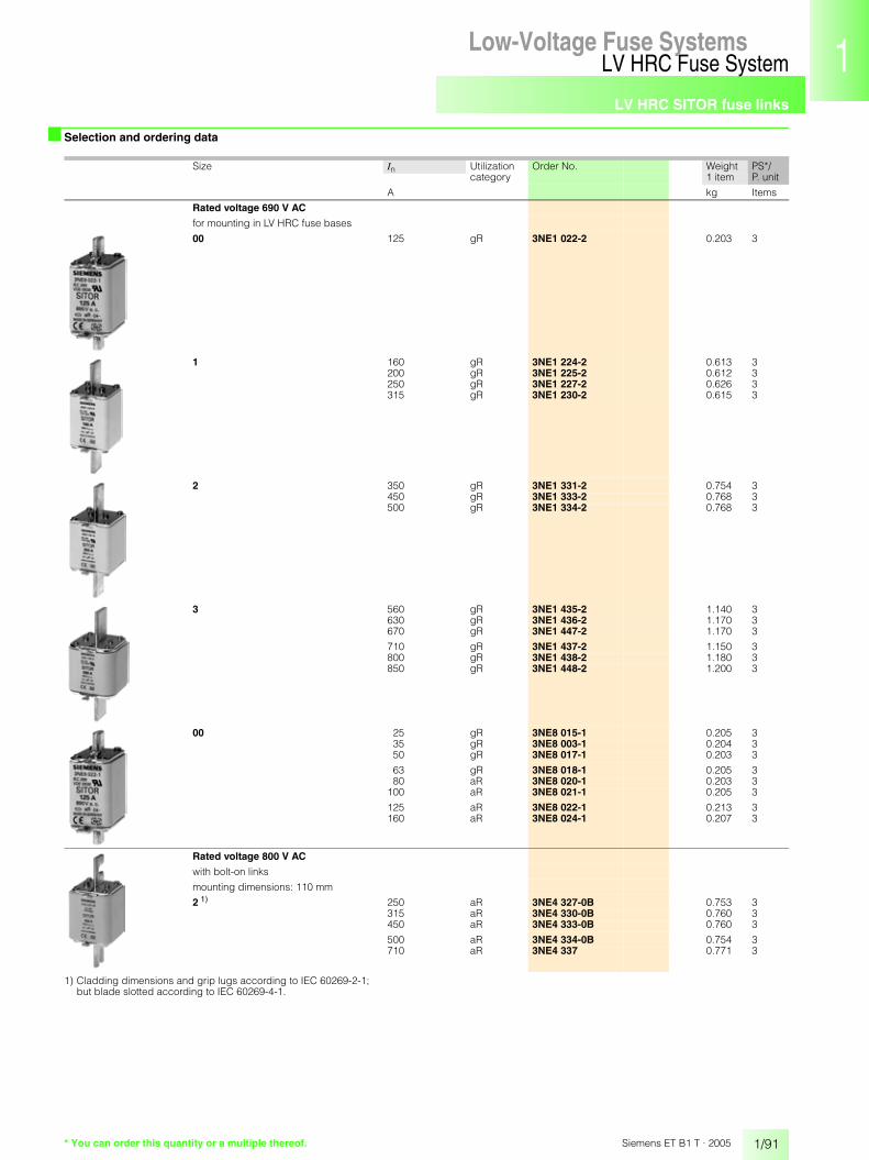
LV HRC SITOR fuse links
1/91
LV HRC Fuse SystemLow-Voltage Fuse Systems 1
345678910
1213
Siemens ET B1 T · 2005
■ Selection and ordering data
1) Cladding dimensions and grip lugs according to IEC 60269-2-1;but blade slotted according to IEC 60269-4-1.
Size In Utilization Order No. Weight PS*/P. unitcategory 1 item
A kg Items
Rated voltage 690 V AC
for mounting in LV HRC fuse bases
00 125 gR 3NE1 022-2 0.203 3
1 160 gR 3NE1 224-2 0.613 3200 gR 3NE1 225-2 0.612 3250 gR 3NE1 227-2 0.626 3315 gR 3NE1 230-2 0.615 3
2 350 gR 3NE1 331-2 0.754 3450 gR 3NE1 333-2 0.768 3500 gR 3NE1 334-2 0.768 3
3 560 gR 3NE1 435-2 1.140 3630 gR 3NE1 436-2 1.170 3670 gR 3NE1 447-2 1.170 3
710 gR 3NE1 437-2 1.150 3800 gR 3NE1 438-2 1.180 3850 gR 3NE1 448-2 1.200 3
00 25 gR 3NE8 015-1 0.205 335 gR 3NE8 003-1 0.204 350 gR 3NE8 017-1 0.203 3
63 gR 3NE8 018-1 0.205 380 aR 3NE8 020-1 0.203 3
100 aR 3NE8 021-1 0.205 3
125 aR 3NE8 022-1 0.213 3160 aR 3NE8 024-1 0.207 3
Rated voltage 800 V AC
with bolt-on links
mounting dimensions: 110 mm
2 1) 250 aR 3NE4 327-0B 0.753 3315 aR 3NE4 330-0B 0.760 3450 aR 3NE4 333-0B 0.760 3
500 aR 3NE4 334-0B 0.754 3710 aR 3NE4 337 0.771 3
* You can order this quantity or a multiple thereof.

LV HRC SITOR fuse links
1/92
LV HRC Fuse SystemLow-Voltage Fuse Systems
Siemens ET B1 T · 2005
■ Selection and ordering data
1) Cladding dimensions and grip lugs according to IEC 60269-2-1;but blade slotted according to IEC 60269-4-1.
2) Rated voltage 900 V AC.
3) Rated voltage 800 V AC.
4) Rated voltage 690 V AC.
5) Design corresponds to 3NE6 4.. and 3NE9 4...
6) M12 screw connection
Size In Utilization Order No. Weight PS*/P. unitcategory 1 item
A kg Items
Rated voltage 1000 V AC
for mounting in LV HRC fuse bases
0 32 gR 3NE4 101 0.278 340 3NE4 102 0.277 350 3NE4 117 0.276 3
63 aR 3NE4 118 0.279 380 3NE4 120 0.276 3
100 3NE4 121 0.278 3
125 3NE4 122 0.279 3160 3NE4 124 0.279 3
with bolt-on links
mounting dimensions: 110 mm
1 1) 100 aR 3NE3 221 0.580 3125 3NE3 222 0.568 3160 3NE3 224 0.573 3
200 3NE3 225 0.570 3250 3NE3 227 0.580 3315 3NE3 230-0B 0.585 3
350 3NE3 231 0.590 3400 3NE3 232-0B 0.576 3450 3NE3 233 0.720 3
2 1) 400 aR 3NE3 332-0B 0.759 3450 3NE3 333 0.748 3500 3NE3 334-0B 0.753 3
560 3NE3 335 0.756 3630 3NE3 336 0.760 3
710 2) 3NE3 337-8 0.762 3800 3) 3NE3 338-8 0.764 3900 4) 3NE3 340-8 0.753 3
mounting dimensions: 130 mm
3 100 aR 3NE3 421 1.150 3224 3NE3 626 1.300 3315 3NE3 430 1.240 3
400 3NE3 432 1.240 3450 3NE3 635 1.170 3450 5) 3NE3 635-6 1.180 3
500 3NE3 434 1.490 3630 3NE3 636 1.210 3710 3NE3 637 1.190 3
mounting dimensions: 140 mm, M12 screw connection
3 710 aR 3NE3 637-1 1.240 3
Rated voltage 1500 V AC
with bolt-on links
mounting dimensions: 210 mm
3 160 aR 3NE5 424 1.950 2224 3NE5 426 1.960 2315 3NE5 430 1.950 2
350 3NE5 431 1.950 2450 3NE5 433 1.950 2450 6) 3NE5 433-1 1.960 2
250 3NE5 627 1.560 3450 3NE5 633 1.580 3600 3NE5 643 1.580 3
* You can order this quantity or a multiple thereof.

LV HRC SITOR fuse links
1/93
LV HRC Fuse SystemLow-Voltage Fuse Systems 1
345678910
1213
Siemens ET B1 T · 2005
■ Selection and ordering data
1) M12 screw connection
Size In Utilization Order No. Weight PS*/P. unitcategory 1 item
A kg Items
Rated voltage 2000 V AC
with bolt-on links
mounting dimensions: 210 mm
3 200 aR 3NE7 425 1.950 2250 3NE7 427 1.970 2350 3NE7 431 1.980 2400 3NE7 432 1.970 2
450 3NE7 633 1.960 2450 1) 3NE7 633-1 1.980 2525 1) 3NE7 648-1 1.970 2
630 3NE7 636 1.990 2630 1) 3NE7 636-1 2.020 2710 1) 3NE7 637-1 1.990 2
Rated voltage 2500 V AC
with bolt-on links
mounting dimensions: 260 mm
3 400 1) aR 3NE9 632-1 2.540 1500 1) 3NE9 634-1 2.550 1630 1) 3NE9 636-1A 2.550 1
* You can order this quantity or a multiple thereof.
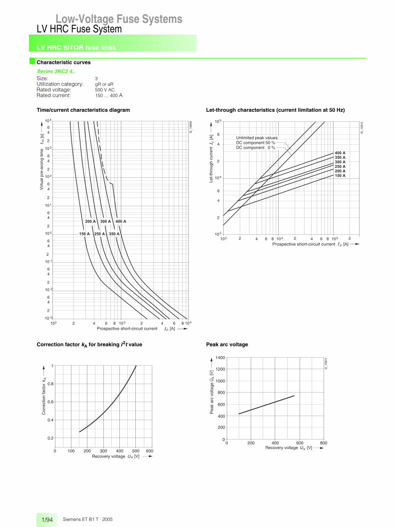
LV HRC SITOR fuse links
1/94
LV HRC Fuse SystemLow-Voltage Fuse Systems
Siemens ET B1 T · 2005
■ Characteristic curves
Series 3NC2 4..Size: 3Utilization category: gR or aRRated voltage: 500 V ACRated current: 150 ... 400 A
Time/current characteristics diagram Let-through characteristics (current limitation at 50 Hz)
Correction factor kA for breaking I2t value Peak arc voltage
210210 -3
2
46
10 -2
64 1038 2 64 1048
2
46
10 -1
2
46
10 0
2
46
10 1
2
46
10 2
2
46
10 3
2
46
104
I2_1
0809
� � � �� � � � �� � � � �
� � � � �� � � � �� � � � �
vs
p � � �
� �
Virt
ual p
re-a
rcin
g tim
e
Prospective short-circuit current
p
c
103 2 64 104810
2
4
6
10
I2_1
0812
4
3
2 64 1058 2
2
4
6
105
���
� � �
� � � � �
� � � � �
� � � � �
� � � � �
� � � � �
� � � �
Prospective short-circuit current
Unlimited peak values:DC component 50 %DC component 0 %
Let-
thro
ugh
curr
ent
0 100 200 300 400 500 600
1
A
w � � �Recovery voltage
Cor
rect
ion
fact
or 0.8
0.6
0.4
0.20 200 400 600 800
400
800
1200
s
w
1400
1000
600
200
0
I2_1
0811
� � �
���
Recovery voltage
Pea
k ar
c vo
ltage
Û

LV HRC SITOR fuse links
1/95
LV HRC Fuse SystemLow-Voltage Fuse Systems 1
345678910
1213
Siemens ET B1 T · 2005
■ Characteristic curves
Series 3NE8 71.-1, 3NE8 70.-1Size: 000Utilization category: gR or aRRated voltage: 690 V AC/700 V DCRated current: 20 ... 63 A
Time/current characteristics diagram Let-through characteristics (current limitation at 50 Hz)
Correction factor kA for breaking I2t value Peak arc voltage
210110 -3
2
46
10 -2
64 1028 2 64 1038
2
46
10 -1
2
46
10 0
2
46
10 1
2
46
10 2
2
46
10 3
2
46
104
I2_1
0813
� � � �� � � �� � � �
� � � � � � �� � � �
vs
p � � �
� �
Virt
ual p
re-a
rcin
g tim
e
Prospective short-circuit current
102 2 64 108
10
2
4
6
2
4
6
3
c
p [A]
[A]
104
102
3 2 64 108 4 2 64 108 5 2 4
� � � �
I2_1
0816
� � � �
� � � �
� � �
� � � �
� � � �
Let-
thro
ugh
curr
ent
Prospective short-circuit current
Unlimited peak values:DC component 50 %DC component 0 %
0 100 200 300 400 500 600
1
700 800
A
w � � �
Cor
rect
ion
fact
or
Recovery voltage
0.2
0.4
0.6
0.8
200 400 500 600 700 800100
s
w
300
1400
1200
1000
800
600
400
200
0� � �
���
0
ÛP
eak
arc
volta
ge
AD
A94
-500
4a-v
Recovery voltage

LV HRC SITOR fuse links
1/96
LV HRC Fuse SystemLow-Voltage Fuse Systems
Siemens ET B1 T · 2005
■ Characteristic curves
Series 3NE8 72.-1, 3NE8 731-1Size: 000Utilization category: aRRated voltage: 690 V AC/700 V DCRated current: 80 ... 315 A
Time/current characteristics diagram Let-through characteristics (current limitation at 50 Hz)
Correction factor kA for breaking I2t value Peak arc voltage
210110 -3
2
46
10 -2
64 1028 2 64 1038 2 4
2
46
10 -1
2
46
10 0
2
46
10 1
2
46
10 2
2
46
10 3
2
46
104
I2_1
0817
6 1048
� � � � �
� � � � �
� � � � �
� � � � �
� � � � �
� � �
� � � � �
vs
p � � �
� �
Virt
ual p
re-a
rcin
g tim
e
Prospective short-circuit current
10
2
4
6
2
4
6
4
c[A
]
105
103
I2_1
0820
6
� � �
� � � � �
� � � � �
� � � � �
� � � � �
� � � � �
� � � � �
102 2 64 108 3 2 64 108 4 2 64 108 5 2 4
p [A]
Let-
thro
ugh
curr
ent
Prospective short-circuit current
Unlimited peak values:DC component 50 %DC component 0 %
0 100 200 300 400 500 600
1
700 800
A
w � � �
Cor
rect
ion
fact
or
AD
A94
-500
3a-v
Recovery voltage
0.2
0.4
0.6
0.8
200 400 500 600 700 800100
s
w
300
1400
1200
1000
800
600
400
200
0� � �
���
0
ÛP
eak
arc
volta
ge
Recovery voltage
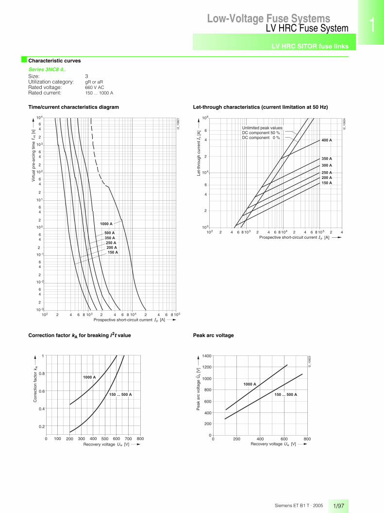
LV HRC SITOR fuse links
1/97
LV HRC Fuse SystemLow-Voltage Fuse Systems 1
345678910
1213
Siemens ET B1 T · 2005
■ Characteristic curves
Series 3NC8 4..Size: 3Utilization category: gR or aRRated voltage: 660 V ACRated current: 150 ... 1000 A
Time/current characteristics diagram Let-through characteristics (current limitation at 50 Hz)
Correction factor kA for breaking I2t value Peak arc voltage
p
vs
210210 -3
2
46
10 -2
64 1038 2 64 1048 2 4
2
46
10 -1
2
46
10 0
2
46
10 1
2
46
10 2
2
46
10 3
2
46
104
I2_1
0821
6 1058
� � � � �
� � � � �
� � � � �
� � � � �
� � � � � �
� � � � �
� � �
� �
Virt
ual p
re-a
rcin
g tim
e
Prospective short-circuit current
102 2 64 108
10
2
4
6
2
4
6
4
c
p [A]
[A]
105
103
3 2 64 108 4 2 64 108 5 2 4
� � � � �
I2_1
0824
� � � � �
� � � � �
� � � � �
� � � � �
� � � �
Let-
thro
ugh
curr
ent
Prospective short-circuit current
Unlimited peak values:DC component 50 %DC component 0 %
0 100 200 300 400 500 600
1
700 800
A
w
� � � � � �
� � � � � � � � � � � � �
� � �
Cor
rect
ion
fact
or
Recovery voltage
0.2
0.4
0.6
0.8
0 200 400 600 800
400
800
1200
s
w
1400
1000
600
200
0
I2_1
0823
� � � � � �
� � � � � � � � � � � � �
� � �
���
Recovery voltage
Pea
k ar
c vo
ltage
Û
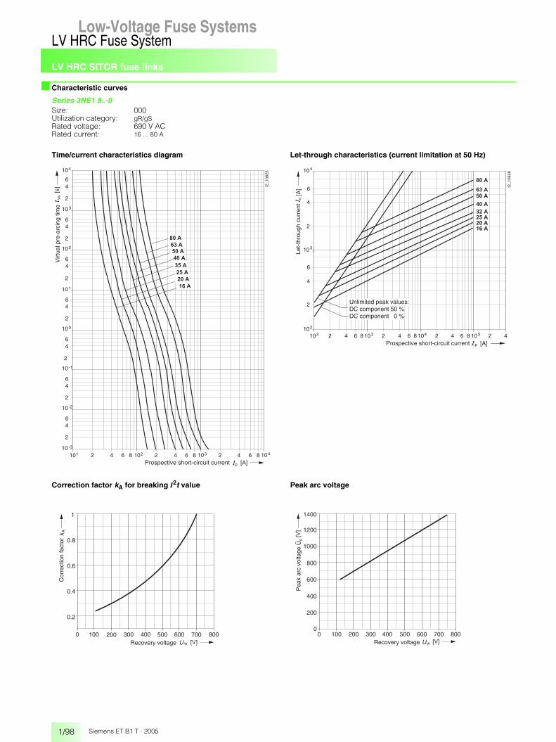
LV HRC SITOR fuse links
1/98
LV HRC Fuse SystemLow-Voltage Fuse Systems
Siemens ET B1 T · 2005
■ Characteristic curves
Series 3NE1 8..-0Size: 000Utilization category: gR/gSRated voltage: 690 V ACRated current: 16 ... 80 A
Time/current characteristics diagram Let-through characteristics (current limitation at 50 Hz)
Correction factor kA for breaking I2t value Peak arc voltage
p
vs
210110 -3
2
46
10 -2
64 1028 2 64 1038 2 4
2
46
10 -1
2
46
10 0
2
46
10 1
2
46
10 2
2
46
10 3
2
46
104
I2_1
0825
6 1048
� � �
� � � �
� � � �
� � � �
� � � �
� � � �
� � � �
� � �
� � �
� �
Virt
ual p
re-a
rcin
g tim
e
Prospective short-circuit current
102 2 64 108
10
2
4
6
2
4
6
3
c
p [A]
[A]
104
102
3 2 64 108 4 2 64 108 5 2 4
� � � �
I2_1
0828
� � � �
� � � �
� � �
� � � �
� � � �
� � � �
� � �
Let-
thro
ugh
curr
ent
Prospective short-circuit current
Unlimited peak values:DC component 50 %DC component 0 %
0 100 200 300 400 500 600
1
700 800
A
w � � �
Cor
rect
ion
fact
or
Recovery voltage
0.2
0.4
0.6
0.8
200 400 500 600 700 800100
s
w
300
1400
1200
1000
800
600
400
200
0� � �
���
0
ÛP
eak
arc
volta
ge
Recovery voltage

LV HRC SITOR fuse links
1/99
LV HRC Fuse SystemLow-Voltage Fuse Systems 1
345678910
1213
Siemens ET B1 T · 2005
■ Characteristic curves
Series 3NE1 02.-0, 3NE1 2..-0Size: 00, 1Utilization category: gR/gSRated voltage: 690 V ACRated current: 100 ... 315 A
Time/current characteristics diagram Let-through characteristics (current limitation at 50 Hz)
Correction factor kA for breaking I2t value Peak arc voltage
p
vs
210210 -3
2
46
10 -2
64 1038 2 64 1048
2
46
10 -1
2
46
10 0
2
46
10 1
2
46
10 2
2
46
10 3
2
46
104
I2_1
0829
� � � � �
� � � � �
� � � � �
� � � � �
� � � � �
� � � � �
Virt
ual p
re-a
rcin
g tim
e
Prospective short-circuit current
p
c
103 2 64 104810
2
4
6
10
I2_1
0831
4
3
2 64 1058 2
2
4
6
105
���
� � �
� � � � �
� � � � �
� � � � �
� � � � �
� � � � � � � �
Prospective short-circuit current
Unlimited peak values:DC component 50 %DC component 0 %
Let-
thro
ugh
curr
ent
0 100 200 300 400 500 600
1
700 800
A
w
� � � � � � � � � �
� � � � � � � � � �
� � �
Cor
rect
ion
fact
or
Recovery voltage
0.2
0.4
0.6
0.8
200 400 500 600 700 800100
s
w
300
1400
1200
1000
800
600
400
200
0� � �
���
0
ÛP
eak
arc
volta
ge
Recovery voltage

LV HRC SITOR fuse links
1/100
LV HRC Fuse SystemLow-Voltage Fuse Systems
Siemens ET B1 T · 2005
■ Characteristic curves
Series 3NE1 33.-0, 3NE1 43.-0Size: 2, 3Utilization category: gR/gSRated voltage: 690 V ACRated current: 350 ... 800 A
Time/current characteristics diagram Let-through characteristics (current limitation at 50 Hz)
Correction factor kA for breaking I2t value Peak arc voltage
p
vs
210210 -3
2
46
10 -2
64 1038 2 64 1048 2 4
2
46
10 -1
2
46
10 0
2
46
10 1
2
46
10 2
2
46
10 3
2
46
104
I2_1
0832
6 1058
� � � � �
� � � � �
� � � �
� � � �
� � � � �
� � � � �
� � � � �
� � � �
� � �
� �
Virt
ual p
re-a
rcin
g tim
e
Prospective short-circuit current
p
c
103 2 64 104810
2
4
6
10
I2_1
0834
4
3
2 64 1058 2
2
4
6
105
���
� � �
� � � � �
� � � �
� � � �
� � � � �
� � � � �
� � � � �
� � � � �
� � � �
Prospective short-circuit current
Unlimited peak values:DC component 50 %DC component 0 %
Let-
thro
ugh
curr
ent
0 100 200 300 400 500 600
1
700 800
A
w � � �
Cor
rect
ion
fact
or
Recovery voltage
0.2
0.4
0.6
0.8
200 400 500 600 700 800100
s
w
300
1400
1200
1000
800
600
400
200
0� � �
���
0
ÛP
eak
arc
volta
ge
Recovery voltage

LV HRC SITOR fuse links
1/101
LV HRC Fuse SystemLow-Voltage Fuse Systems 1
345678910
1213
Siemens ET B1 T · 2005
■ Characteristic curves
Series 3NE1 437.-1, 3NE1 438.-1Size: 3Utilization category: gRRated voltage: 600 V ACRated current: 710 and 800 A
Time/current characteristics diagram Let-through characteristics (current limitation at 50 Hz)
Correction factor kA for breaking I2t value Peak arc voltage
p
vs
210210 -3
2
46
10 -2
64 1038 2 64 1048 2 4
2
46
10 -1
2
46
10 0
2
46
10 1
2
46
10 2
2
46
10 3
2
46
104
I2_1
0835
6 1058
� � � � �
� � � �
� � �
� �
Virt
ual p
re-a
rcin
g tim
e
Prospective short-circuit current
p
c
103 2 64 104810
2
4
6
10
I2_1
0838
5
4
2 64 1058 2
���
� � �
� � � � �
� � � �
Prospective short-circuit current
Unlimited peak values:DC component 50 %DC component 0 %
Let-
thro
ugh
curr
ent
0 100 200 300 400 500 600
1
700 800
A
w � � �
Cor
rect
ion
fact
or
Recovery voltage
0.2
0.4
0.6
0.8
200 400 500 600 700 800100
s
w
300
1400
1200
1000
800
600
400
200
0� � �
���
0
Pea
k ar
c vo
ltage
Recovery voltage
Û

LV HRC SITOR fuse links
1/102
LV HRC Fuse SystemLow-Voltage Fuse Systems
Siemens ET B1 T · 2005
■ Characteristic curves
Series 3NE1 022-2, 3NE1 2..-2, 3NE1 33.-2Size: 00, 1Utilization category: gRRated voltage: 690 V ACRated current: 125 ... 500 A
Time/current characteristics diagram Let-through characteristics (current limitation at 50 Hz)
Correction factor kA for breaking I2t value Peak arc voltage
p
vs
210210 -3
2
46
10 -2
64 1038 2 64 1048
2
46
10 -1
2
46
10 0
2
46
10 1
2
46
10 2
2
46
10 3
2
46
104
I2_1
0839
� � � � �
� � � �
� � � � �
� � � � �
� � � � �
� � � � �
� � � � �
� � � � �
� � �
� �
Virt
ual p
re-a
rcin
g tim
e
Prospective short-circuit current
p
c
103 2 64 104810
2
4
6
10
I2_1
0842
4
3
2 64 1058 2
2
4
6
105
���
� � �
� � � � �
� � � � �
� � � � �
� � � � �
� � � � �
� � � � �
� � � �
� � � � �
Prospective short-circuit current
Unlimited peak values:DC component 50 %DC component 0 %
Let-
thro
ugh
curr
ent
0 100 200 300 400 500 600
1
700 800
A
w
� � � � �
� � � � �
� � �
Cor
rect
ion
fact
or
Recovery voltage
0.2
0.4
0.6
0.8
0 200w
s
2000
1800
1000
800
400
200
400 600 800
I2_1
0841
600
1200
1400
1600
� � � � �
� � � � � � � � � � � � �
� � � � �
� � �
���
0
ÛP
eak
arc
volta
ge
Recovery voltage

LV HRC SITOR fuse links
1/103
LV HRC Fuse SystemLow-Voltage Fuse Systems 1
345678910
1213
Siemens ET B1 T · 2005
■ Characteristic curves
Series 3NE1 4..-2Size: 3Utilization category: gRRated voltage: 690 V ACRated current: 560 ... 850 A
Time/current characteristics diagram Let-through characteristics (current limitation at 50 Hz)
Correction factor kA for breaking I2t value Peak arc voltage
p
vs
210210 -3
2
46
10 -2
64 1038 2 64 1048 2 4
2
46
10 -1
2
46
10 0
2
46
10 1
2
46
10 2
2
46
10 3
2
46
104
I2_1
0843
6 1058
� � � �
� � � � �
� � � � �
� � � � �
� � � � �
� � � �
� � �
� �
Virt
ual p
re-a
rcin
g tim
e
Prospective short-circuit current
p
c
103 2 64 104810
2
4
6
10
I2_1
0846
5
4
2 64 1058 2
���
� � �
� � � � �
� � � � �
� � � � �
� � � � �
� � � �
� � � �
Prospective short-circuit current
Unlimited peak values:DC component 50 %DC component 0 %
Let-
thro
ugh
curr
ent
0 100 200 300 400 500 600
1
700 800
A
w � � �
Cor
rect
ion
fact
or
Recovery voltage
0.2
0.4
0.6
0.8
0 200w
s
2000
1800
1000
800
400
200
400 600 800
I2_1
0845
600
1200
1400
1600
� � �
���
0
ÛP
eak
arc
volta
ge
Recovery voltage

LV HRC SITOR fuse links
1/104
LV HRC Fuse SystemLow-Voltage Fuse Systems
Siemens ET B1 T · 2005
■ Characteristic curves
Series 3NE8 0..-1Size: 00Utilization category: gR or aRRated voltage: 690 V ACRated current: 25 ... 160 A
Time/current characteristics diagram Let-through characteristics (current limitation at 50 Hz)
Correction factor kA for breaking I2t value Peak arc voltage
p
vs
210110 -3
2
46
10 -2
64 1028 2 64 1038 2 4
2
46
10 -1
2
46
10 0
2
46
10 1
2
46
10 2
2
46
10 3
2
46
104
I2_1
0847
6 1048
� � � � �
� � �
� � � �
� � � �
� � � �
� � � �
� � � � �
� � � � �
� � �
� �
Virt
ual p
re-a
rcin
g tim
e
Prospective short-circuit current
102 2 64 108
10
2
4
6
2
4
6
3
c
p [A]
[A]
104
102
3 2 64 108 4 2 64 108 5 2 4
� � � �
I2_1
0850
� � � �
� � � �
� � � �
� � �
� � � � �
� � � � �
� � � � �
Let-
thro
ugh
curr
ent
Prospective short-circuit current
Unlimited peak values:DC component 50 %DC component 0 %
0 100 200 300 400 500 600
1
700 800
A
w � � �
Cor
rect
ion
fact
or
Recovery voltage
0.2
0.4
0.6
0.8
0 200w
s
2000
1800
1000
800
400
200
400 600 800
I2_1
0849
600
1200
1400
1600
� � �
���
0
Pea
k ar
c vo
ltage
Recovery voltage
Û
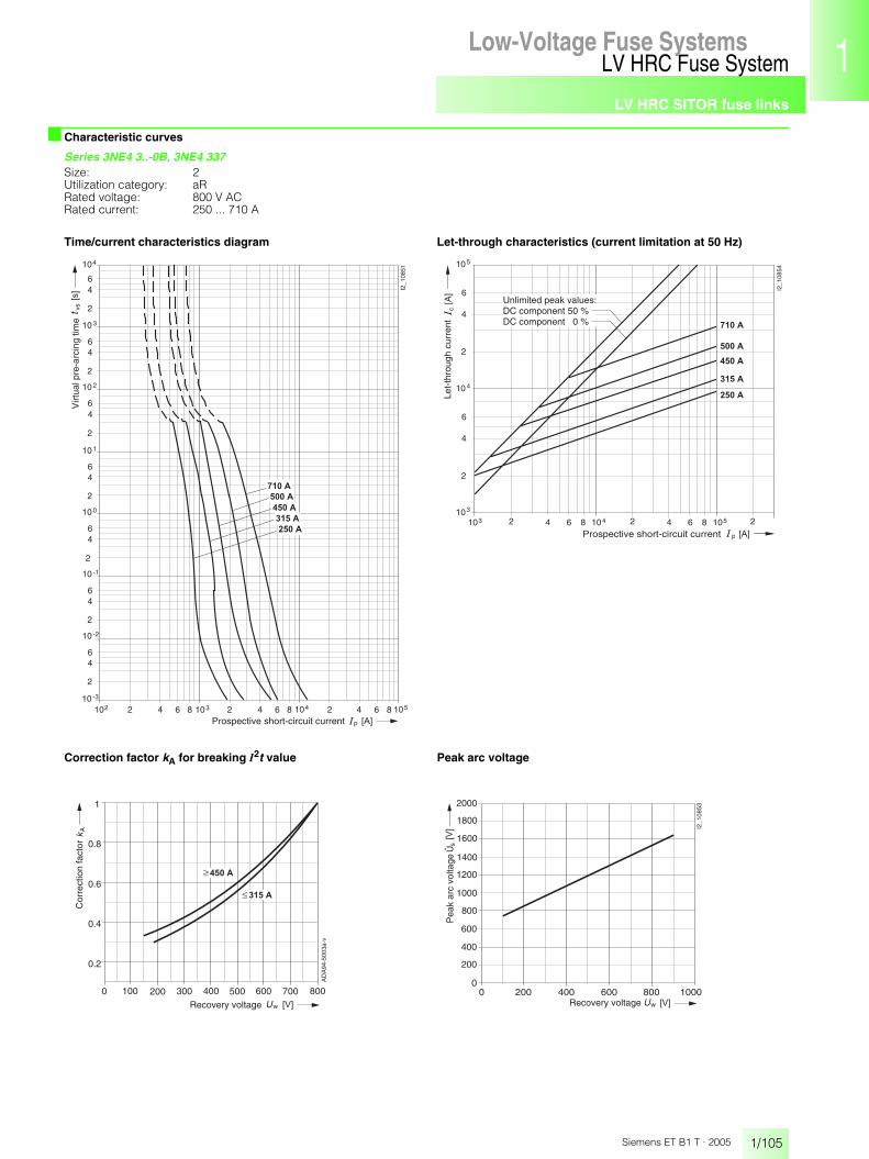
LV HRC SITOR fuse links
1/105
LV HRC Fuse SystemLow-Voltage Fuse Systems 1
345678910
1213
Siemens ET B1 T · 2005
■ Characteristic curves
Series 3NE4 3..-0B, 3NE4 337Size: 2Utilization category: aRRated voltage: 800 V ACRated current: 250 ... 710 A
Time/current characteristics diagram Let-through characteristics (current limitation at 50 Hz)
Correction factor kA for breaking I2t value Peak arc voltage
p
vs
210210 -3
2
46
10 -2
64 1038 2 64 1048 2 4
2
46
10 -1
2
46
10 0
2
46
10 1
2
46
10 2
2
46
10 3
2
46
104
I2_1
0851
6 1058
� � � � �
� � � � �
� � � �
� � � � �
� � � � �
� � �
� �
Virt
ual p
re-a
rcin
g tim
e
Prospective short-circuit current
p
c
103 2 64 104810
2
4
6
10
I2_1
0854
4
3
2 64 1058 2
2
4
6
105
���
� � �
� � � � �
� � � � �
� � � �
� � � � �
� � � � �
Prospective short-circuit current
Unlimited peak values:DC component 50 %DC component 0 %
Let-
thro
ugh
curr
ent
0 100 200 300 400 500 600
1
700 800
A
w
� � � �
� � � � �
� � �
Cor
rect
ion
fact
or
AD
A94
-500
3a-v
Recovery voltage
0.2
0.4
0.6
0.8
0 200w
s
2000
1800
1000
800
400
200
400 600 800
I2_1
0853
600
1200
1400
1600
1000� � �
���
0
Pea
k ar
c vo
ltage
Recovery voltage
Û
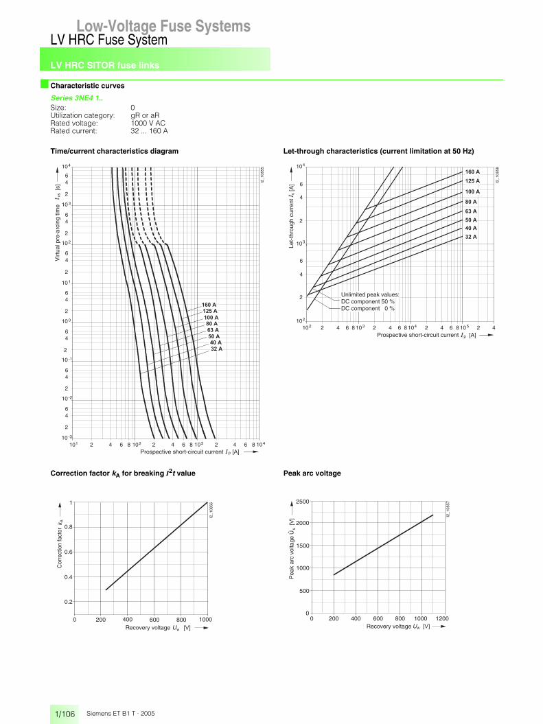
LV HRC SITOR fuse links
1/106
LV HRC Fuse SystemLow-Voltage Fuse Systems
Siemens ET B1 T · 2005
■ Characteristic curves
Series 3NE4 1..Size: 0Utilization category: gR or aRRated voltage: 1000 V ACRated current: 32 ... 160 A
Time/current characteristics diagram Let-through characteristics (current limitation at 50 Hz)
Correction factor kA for breaking I2t value Peak arc voltage
p
vs
210110 -3
2
46
10 -2
64 1028 2 64 1038 2 4
2
46
10 -1
2
46
10 0
2
46
10 1
2
46
10 2
2
46
10 3
2
46
104
I2_1
0855
6 1048
� � � � �
� � �
� � � �
� � � �
� � �
� � � �
� � � � �
� � � � �
� �
� � �
Virt
ual p
re-a
rcin
g tim
e
Prospective short-circuit current
102 2 64 108
10
2
4
6
� � � � �
2
4
6
3
� � � � �
c
p [A]
[A]
104
102
3 2 64 108 4 2 64 108 5 2 4
� � � �
I2_1
0858
� � �
� � � �
� � � � �
� � � �
� � �
Let-
thro
ugh
curr
ent
Prospective short-circuit current
Unlimited peak values:DC component 50 %DC component 0 %
0 200 400 600
1
800 1000
A
w � � �
I2_1
0856
Cor
rect
ion
fact
or
0.8
0.6
0.4
0.2
Recovery voltage
0 200 400 600 800 1000 1200
500
1000
1500
2000
2500
0
s
w � � �
���
I2_1
0857
Pea
k ar
c vo
ltage
Recovery voltage
Û

LV HRC SITOR fuse links
1/107
LV HRC Fuse SystemLow-Voltage Fuse Systems 1
345678910
1213
Siemens ET B1 T · 2005
■ Characteristic curves
Series 3NE3 22.Size: 1Utilization category: aRRated voltage: 1000 V ACRated current: 100 ... 225 A
Time/current characteristics diagram Let-through characteristics (current limitation at 50 Hz)
Correction factor kA for breaking I2t value Peak arc voltage
p
vs
210110 -3
2
46
10 -2
64 1028 2 64 1038 2 4
2
46
10 -1
2
46
10 0
2
46
10 1
2
46
10 2
2
46
10 3
2
46
104
I2_1
0859
6 1048
� � � � �
� � � � �
� � � � �
� �
� � �
� � � � �
� � � � �
Virt
ual p
re-a
rcin
g tim
e
Prospective short-circuit current
102 2 64 108
10
2
4
6
2
4
6
3
c
p [A]
[A]
104
102
3 2 64 108 4 2 64 108 5 2 4
I2_1
0862
2
� � � � �
� � � � �
� � � � �
� � � � �
� � � � �
Let-
thro
ugh
curr
ent
Prospective short-circuit current
Unlimited peak values:DC component 50 %DC component 0 %
0 200 400 600
1
800 1000
A
w � � �
I2_1
0860
Cor
rect
ion
fact
or
0.8
0.6
0.4
0.2
Recovery voltage
0 200 400 600 800 1000 1200
500
1000
1500
2000
2500
0
s
w � � �
���
I2_1
0861
ÛP
eak
arc
volta
ge
Recovery voltage

LV HRC SITOR fuse links
1/108
LV HRC Fuse SystemLow-Voltage Fuse Systems
Siemens ET B1 T · 2005
■ Characteristic curves
Series 3NE3 23.Size: 1Utilization category: aRRated voltage: 1000 V ACRated current: 315 ... 450 A
Time/current characteristics diagram Let-through characteristics (current limitation at 50 Hz)
Correction factor kA for breaking I2t value Peak arc voltage
p
vs
210210 -3
2
46
10 -2
64 1038 2 64 1048
2
46
10 -1
2
46
10 0
2
46
10 1
2
46
10 2
2
46
10 3
2
46
104
I2_1
0863
� � � �
� � �
� � � �
� � � � �
� � � � �
� �
Virt
ual p
re-a
rcin
g tim
e
Prospective short-circuit current
p
c
103 2 64 104810
2
4
6
10
I2_1
0864
4
3
2 64 1058 2
2
4
6
105
���
� � �
� � � � �
� � � � �
� � � �
� � � �
Prospective short-circuit current
Unlimited peak values:DC component 50 %DC component 0 %
Let-
thro
ugh
curr
ent
0 200 400 600
1
800 1000
A
w � � �
I2_1
0860
Cor
rect
ion
fact
or
0.8
0.6
0.4
0.2
Recovery voltage
0 200 400 600 800 1000 1200
500
1000
1500
2000
2500
0
s
w � � �
���
I2_1
0861
ÛP
eak
arc
volta
ge
Recovery voltage
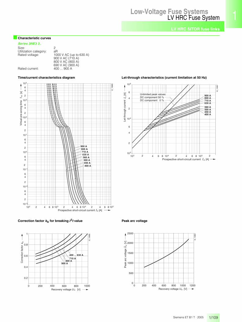
LV HRC SITOR fuse links
1/109
LV HRC Fuse SystemLow-Voltage Fuse Systems 1
345678910
1213
Siemens ET B1 T · 2005
■ Characteristic curves
Series 3NE3 3..Size: 2Utilization category: aRRated voltage: 1000 V AC (up to 630 A)
900 V AC (710 A)800 V AC (800 A)690 V AC (900 A)
Rated current: 400 ... 900 A
Time/current characteristics diagram Let-through characteristics (current limitation at 50 Hz)
Correction factor kA for breaking I2t value Peak arc voltage
p
vs
210210 -3
2
46
10 -2
64 1038 2 64 1048 2 4
2
46
10 -1
2
46
10 0
2
46
10 1
2
46
10 2
2
46
10 3
2
46
104
I2_1
0865
6 1058
� � � �
� � � �
� � � � �
� �
� � �
� � � � �
� � � � �
� � � � �
� � � �
� � � � �
Virt
ual p
re-a
rcin
g tim
e
Prospective short-circuit current
p
c
103 2 64 104810
2
4
6
� � � �
10
I2_1
0867
4
3
2 64 1058 2
2
4
6
105
� � � �
� � � � �
� � � � �
� � � � �
� � � � �
� � � �
� � � � ����
� � �Prospective short-circuit current
Unlimited peak values:DC component 50 %DC component 0 %
Let-
thro
ugh
curr
ent
0 200 400 600
1
800 1000
A
w � � �
I2_1
0866
� � � �
� � � � �
� � � � � � � � � � � �
� � � � �
Cor
rect
ion
fact
or
0.8
0.6
0.4
0.2
Recovery voltage
0 200 400 600 800 1000 1200
500
1000
1500
2000
2500
0
s
w � � �
���
I2_1
0861
ÛP
eak
arc
volta
ge
Recovery voltage

LV HRC SITOR fuse links
1/110
LV HRC Fuse SystemLow-Voltage Fuse Systems
Siemens ET B1 T · 2005
■ Characteristic curves
Series 3NE3 4.., 3NE3 6..Size: 3Utilization category: aRRated voltage: 1000 V ACRated current: 100 ... 710 A
Time/current characteristics diagram Let-through characteristics (current limitation at 50 Hz)
Correction factor kA for breaking I2t value Peak arc voltage
p
vs
210210 -3
2
46
10 -2
64 1038 2 64 1048 2 4
2
46
10 -1
2
46
10 0
2
46
10 1
2
46
10 2
2
46
10 3
2
46
104
I2_1
0868
6 1058
� � � � �
� � � �
� � � � �
� �
� � �
� � � �
� � � �
� � � � �
� � � � �
� � � � �
Virt
ual p
re-a
rcin
g tim
e
Prospective short-circuit current
p
103 2 64 1048
I2_
10
87
1
2 64 1058 2� � �
6 8
� � � � �
� � � �
� � � � �
� � � �
� � � �
� � � � �
� � � � �
� � � � �
10
2
4
6
104
3
2
4
Prospective short-circuit current
Unlimited peak values:DC component 50 %DC component 0 %
Let-
thro
ugh
curr
ent
c���
0 200 400 600
1
800 1000
A
w � � �
I2_1
0869
Cor
rect
ion
fact
or
0.8
0.6
0.4
0.2
Recovery voltage0 200 400 600 800 1000 1200
400
800
1200
2000
0
s
w � � �
���
I2_1
0870
200
600
1000
1400
1600
1800
Pea
k ar
c vo
ltage
Recovery voltage
Û

LV HRC SITOR fuse links
1/111
LV HRC Fuse SystemLow-Voltage Fuse Systems 1
345678910
1213
Siemens ET B1 T · 2005
■ Characteristic curves
Series 3NE5 4..Size: 3Utilization category: aRRated voltage: 1500 V ACRated current: 160 ... 600 A
Time/current characteristics diagram Let-through characteristics (current limitation at 50 Hz)
Correction factor kA for breaking I2t value Peak arc voltage
p
vs
210210 -3
2
46
10 -2
64 1038 2 64 1048 2 4
2
46
10 -1
2
46
10 0
2
46
10 1
2
46
10 2
2
46
10 3
2
46
104
I2_1
0872
6 1058
� � � � �
� � � �
� � � � �
� �
� � �
� � � � �
� � � �
Virt
ual p
re-a
rcin
g tim
e
Prospective short-circuit current
p
103 2 64 104
I2_
108
75
2 64 1058 2� � �
8
� � � � �
� � � �
� � � � �
� � � � �
� � � �
2
4
6
104
3
2
4
10
Prospective short-circuit current
Unlimited peak values:DC component 50 %DC component 0 %
Let-
thro
ugh
curr
ent
c���
0 500
1
15001000
w
A
� � �
Cor
rect
ion
fact
or
0.2
0.4
0.6
0.8
I201
_108
73
Recovery voltage
0 400 800 1200 1600 2000
800
2400
4000
0
s
w � � �
���
I2_1
0874
400
1200
2000
2800
3200
3600
1600
Pea
k ar
c vo
ltage
Recovery voltage
Û

LV HRC SITOR fuse links
1/112
LV HRC Fuse SystemLow-Voltage Fuse Systems
Siemens ET B1 T · 2005
■ Characteristic curves
Series 3NE5 6..Size: 3Utilization category: aRRated voltage: 1500 V ACRated current: 250 ... 600 A
Time/current characteristics diagram Let-through characteristics (current limitation at 50 Hz)
Correction factor kA for breaking I2t value Peak arc voltage
p
vs
210210 -3
2
46
10 -2
64 1038 2 64 1048 2 4
2
46
10 -1
2
46
10 0
2
46
10 1
2
46
10 2
2
46
10 3
2
46
104
I2_1
0876
6 1058
� �
� � �
� � � � �
� � � �
� � � � �
Virt
ual p
re-a
rcin
g tim
e
Prospective short-circuit current
p
103 2 64 104
I2_
10
87
7
2 64 1058 2� � �
8
� � � � �
� � � �
� � � � �
c���
10
2
4
6
104
3
2
4
Prospective short-circuit current
Unlimited peak values:DC component 50 %DC component 0 %
Let-
thro
ugh
curr
ent
0 500
1
15001000
w
A
� � �
Cor
rect
ion
fact
or
0.2
0.4
0.6
0.8
I201
_108
73
Recovery voltage
0 400 800 1200 1600 2000
800
2400
4000
0
s
w � � �
���
I2_1
0874
400
1200
2000
2800
3200
3600
1600
Pea
k ar
c vo
ltage
Recovery voltage
Û

LV HRC SITOR fuse links
1/113
LV HRC Fuse SystemLow-Voltage Fuse Systems 1
345678910
1213
Siemens ET B1 T · 2005
■ Characteristic curves
Series 3NE7 4.., 3NE7 6..Size: 3Utilization category: aRRated voltage: 2000 V ACRated current: 200 to 710 A
Time/current characteristics diagram Let-through characteristics (current limitation at 50 Hz)
Correction factor kA for breaking I2t value Peak arc voltage
p
vs
210210 -3
2
46
10 -2
64 1038 2 64 1048 2 4
2
46
10 -1
2
46
10 0
2
46
10 1
2
46
10 2
2
46
10 3
2
46
104
I2_1
0878
6 1058
� �
� � �
� � � � �
� � � � �
� � � � �
� � � �
� � � �
� � � � �
� � � � �
� � � � �
Virt
ual p
re-a
rcin
g tim
e
Prospective short-circuit current
p
c
103 2 64 104810
2
4
6
� � � � �
10
I2_1
0881
4
3
2 64 1058 2
2
4
6
105
� � � � �
���
� � �
� � � � �
� � � � � �
� � � � �
� � � � �
� � � � �
Prospective short-circuit current
Unlimited peak values:DC component 50 %DC component 0 %
Let-
thro
ugh
curr
ent
0 500
1
15001000w
A
� � �
2000
Cor
rect
ion
fact
or
0.2
0.4
0.6
0.8
AD
A94
-502
9b
Recovery voltage
0 400 800 1200 1600 2000 2400
800
2400
4000
0
s
w � � �
���
I2_1
0880
400
2000
2800
3200
3600
1200
1600
Pea
k ar
c vo
ltage
Recovery voltage
Û

LV HRC SITOR fuse links
1/114
LV HRC Fuse SystemLow-Voltage Fuse Systems
Siemens ET B1 T · 2005
■ Characteristic curves
Series 3NE9 63.Size: 3Utilization category: aRRated voltage: 2500 V ACRated current: 400 ... 630 A
Time/current characteristics diagram Let-through characteristics (current limitation at 50 Hz)
Correction factor kA for breaking I2t value Peak arc voltage
p
vs
210210 -3
2
46
10 -2
64 1038 2 64 1048 2 4
2
46
10 -1
2
46
10 0
2
46
10 1
2
46
10 2
2
46
10 3
2
46
104
I2_1
0882
6 1058
� �
� � �
� � � �
� � � � �
� � � � �
Virt
ual p
re-a
rcin
g tim
e
Prospective short-circuit current
p
c
103 2 64 104810
2
4
6
10
I2_1
0885
4
3
2 64 1058 2
2
4
6
105
���
� � �
� � � �
� � � � �
� � � � �
Prospective short-circuit current
Unlimited peak values:DC component 50 %DC component 0 %
Let-
thro
ugh
curr
ent
0 400 800 1200 1600 2000 2400
1
2800
A
w � � �
Cor
rect
ion
fact
or
Recovery voltage
0.2
0.4
0.6
0.8
0 500 1000 1500 2000 2500 3000
6000
0
s
w � � �
���
I2_1
0884
2000
1000
3000
4000
5000
Pea
k ar
c vo
ltage
Recovery voltage
Û

LV HRC SITOR fuse links
1/115
LV HRC Fuse SystemLow-Voltage Fuse Systems 1
345678910
1213
Siemens ET B1 T · 2005
■ Dimensional drawings
3NC2 4.., 3NC8 4.. 3NC2 4..-3, 3NC8 4..-3
7060
1814 12
81
10 670
108
140
I2 11336
71,5
11,5
18
7060
12
1814 12
14
81
10 670
108
140
71,5
11,5
11,5
I2_11337
3NE8 7..-1 3NE1 8..-0 3NE1 02.-0, 3NE1 022-2, 3NE8 0..-1
8,5
8,5
78 100
54
I2_1
1343
21
40
679
,9
50,3 2,
3
I2_06713
10
53,3
20
35,8
15
21
40,5 53,8
5349,4 2,
210
I2_06714
6
48
3079
6035,8
15
3NE1 2..-0, 3NE1 2..-2 3NE1 33.-0, 3NE1 33.-2 3NE1 43.-0, 3NE1 43.-1, 3NE1 4..-2
10
40,5
52
527366
,53
I2_06715
25
63,5
613
5
I2_0
707147,5
25
7260
606
1066
,53
73 149
7015
1
I2_06717
10
6
60,482,1
682,
5
73
70
32

LV HRC SITOR fuse links
1/116
LV HRC Fuse SystemLow-Voltage Fuse Systems
Siemens ET B1 T · 2005
■ Dimensional drawings
3NE4 3..-0B, 3NE4 337 3NE4 1..
60
7148
10 660
I2_11338
10,514,511,5 12,5
14,511,5 12,5
107,
5
141,
5
73,5
10,5
10
306
15 14
47
65 125
58
I2_06450
3NE3 4.., 3NE3 6.., 3NE3 637-1, 3NE5 4.., 3NE5 433-1, 3NE5 6.., 3NE7 4.., 3NE7 6.., 3NE9 63.-1
Type Dimensions
a b c d
3NE3 4.., 3NE3 6.. 160 128 11.5 91.5
3NE3 635-6 see adjacent drawing
3NE3 637-1 170 138 13 91.5
3NE5 4.., 3NE7 4.., 240 208 11.5 171.53NE7 6..
3NE5 433-1, 240 208 13 171.53NE7 6..-1
3NE5 6.. 200 168 11.5 131.5
3NE9 63.-1 287 255 13 220
10 670
b ac
c
706081
14 18 12
14 18 12
d
I2_11339
3NE3 22., 3NE3 23., 3NE3 3..
Type Dimensions
a b c d e f g
3NE3 22., 3NE3 23. 135 31 12.5 40.5 13.5 52 63.5
3NE3 3.. 149 38 19.5 47.5 15 60 72
3NE3 635-6
I2_0
6473
a10
f6
73 a10
,5
c11
0
b12,512,5
10,5
d ef
g
10
70
M10
�28
70 96109
10
81,5 I2_1
1340

LV HRC SITOR fuse links
1/117
LV HRC Fuse SystemLow-Voltage Fuse Systems 1
3456789
10
1213
Siemens ET B1 T · 2005
■ More information
StandardsThe SITOR fuse links comply with the following standards:• IEC 60269-4• EN 60269-4If noted in the selection and ordering data and characteristic curves, the SITOR fuse links also comply with the following standards and regulations:• IEC 60269-2-1
DIN VDE 0636-201(for installation in LV HRC fuse bases according to VDE 0636/201, as well as in fuse switch disconnectors and switch disconnectors with fuses)
• uThe following SITOR fuse links and LV HRC fuse bases are also u recognized:
• IEC 60269-4-1DIN VDE 0636-401(for screwing onto power rail). SITOR fuse links of size 1 to 3 with gauge 110 mm are also suitable for installation in LV HRC fuse bases according to IEC 60269-2-1 and in fuse switch disconnec-tors and switch disconnectors with fuses.
•All SITOR fuse links with rated voltage Un � 1000 V are CE-marked according to the low-voltage Directive 73/23/EWG. The CE marking confirms conformance of the products with the require-ments of the Directive.
Environment-friendly recyclingIn 1995, seven German manufacturers of LV HRC/HV HRC fuse links founded a non-profit association.
LV HRC/HV HRC Recycling
The objective is to provide a useful recycling option for used fuse links and determine an acceptable disposal concept that meets all the requirements of modern environment protection. Used fuse links are sorted according to product type and are ac-cepted back without packaging for recycling, melted down and the recovered materials are fed back into the material cycle.In accordance with the regulations, statutes and articles of the association, any surplus from the recycling process is donated to a university in order to encourage research in the area of fuse link technology.For further information, please visit our Web site at:http://www.nh-hh-recycling.de
DisclaimerThe products described here were developed as part of an overall plant or machine to perform safety-related functions. A complete fail-safe system usually contains sensors, evaluation units, signaling units and concepts for failsafe disconnection. It is the responsibility of the manufacturer of a plant or machine to ensure the correct over-all function. Siemens AG, its branches and affiliated companies (hereafter "Siemens"), is not in a position to guarantee the function of an overall plant or machine that was not designed by Siemens.Siemens can accept no liability for recommendations, either explicit or implicit, contained in the following description. Furthermore, no warranty or liability claims above and beyond those provided for in the Siemens General Terms and Conditions can be derived from the description.
CautionFuses must always be fitted by a qualified technician.
Series Registration number Reference
3NC1 0..3NC1 4..3NC2 2..3NE1 ...3NE3 2..3NE3 3..3NE4 1..3NE8 0..-13NE8 7..-1
JFHR2 E167357
3NC1 1.. JDDZ E223216
3NC1 038-.3NC1 09.3NC1 49.3NC2 29.
IZLT2 E220063
3NH3 0303NH3 1203NH3 2303NH3 3303NH3 430
(JFHR2) (E171267)
NH HH
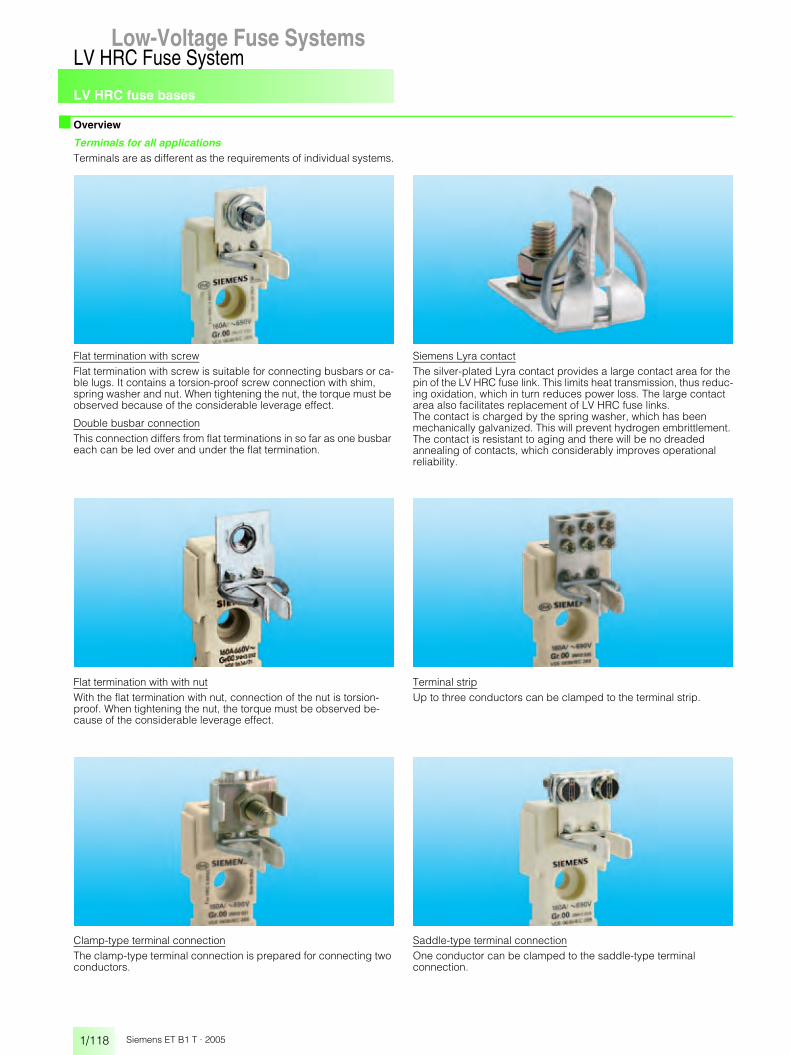
LV HRC fuse bases
1/118
LV HRC Fuse SystemLow-Voltage Fuse Systems
Siemens ET B1 T · 2005
■ Overview
Terminals for all applicationsTerminals are as different as the requirements of individual systems.
Flat termination with screwFlat termination with screw is suitable for connecting busbars or ca-ble lugs. It contains a torsion-proof screw connection with shim, spring washer and nut. When tightening the nut, the torque must be observed because of the considerable leverage effect.
Double busbar connectionThis connection differs from flat terminations in so far as one busbar each can be led over and under the flat termination.
Siemens Lyra contactThe silver-plated Lyra contact provides a large contact area for the pin of the LV HRC fuse link. This limits heat transmission, thus reduc-ing oxidation, which in turn reduces power loss. The large contact area also facilitates replacement of LV HRC fuse links.The contact is charged by the spring washer, which has been mechanically galvanized. This will prevent hydrogen embrittlement. The contact is resistant to aging and there will be no dreaded annealing of contacts, which considerably improves operational reliability.
Flat termination with with nutWith the flat termination with nut, connection of the nut is torsion-proof. When tightening the nut, the torque must be observed be-cause of the considerable leverage effect.
Terminal stripUp to three conductors can be clamped to the terminal strip.
Clamp-type terminal connectionThe clamp-type terminal connection is prepared for connecting two conductors.
Saddle-type terminal connectionOne conductor can be clamped to the saddle-type terminal connection.
Low-Voltage Fuse Systems

LV HRC fuse bases
1/119
LV HRC Fuse SystemLow-Voltage Fuse Systems 1
345678910
1213
Siemens ET B1 T · 2005
■ Technical specifications
1) Also suitable for 1000-V SITOR fuse links.
LV HRC bases, LV HRC bus-mounting basesSize 000/00 0 1 2 3 4 4 A
Rated current In A 160 160 250 400 630 1250 1250
Rated voltage Un V AC 690 1) 690 1)
V DC 250 440
Rated breaking capacity kA AC 120
kA DC 25
Flat terminations
screw M8 M10 M12 M16
nut M8 –
max. tightening torque Nm 14 38 65
Clamp-type terminal connection
conductor cross-section mm2 2.5 ... 50 –
Saddle-type terminal connection
conductor cross-section mm2 6 ... 70 –
Box terminal
conductor cross-section mm2 2.5 ... 50
Terminal strip
conductor cross-section, 3-wire mm2 1.5 ... 16 –
max. torquefor attachment of LV HRC base
Nm 2 2.5 –
LV HRC fuse bases with slewing equipmentSize 000/00 1 2/3 4 A
Rated voltage Un V AC 690
V DC 440
Power loss W 4 5 20 32
Flat terminations
screw M8 M10 M12 M16
nut M8 –
max. tightening torque Nm 14 38 65
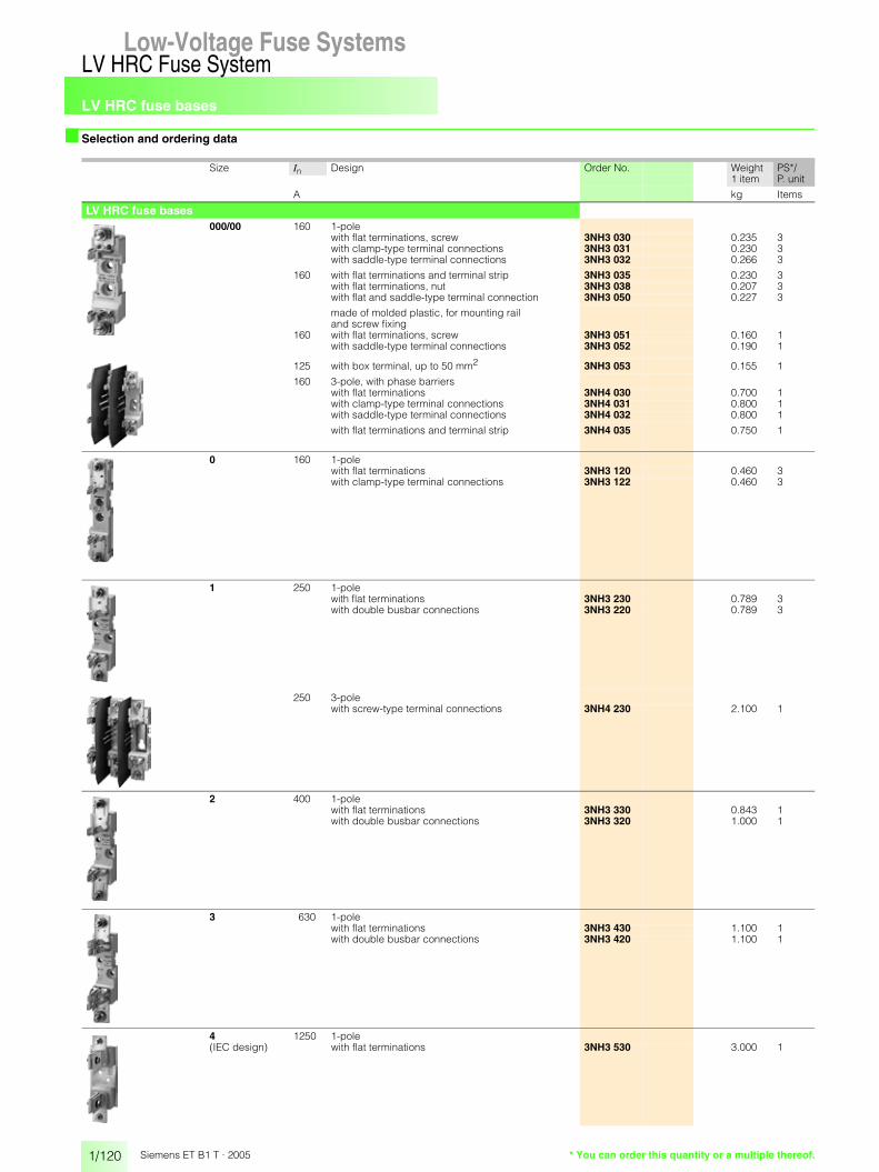
LV HRC fuse bases
1/120
LV HRC Fuse SystemLow-Voltage Fuse Systems
Siemens ET B1 T · 2005
■ Selection and ordering data
Size In Design Order No. Weight PS*/P. unit1 item
A kg Items
LV HRC fuse bases000/00 160 1-pole
with flat terminations, screw 3NH3 030 0.235 3with clamp-type terminal connections 3NH3 031 0.230 3with saddle-type terminal connections 3NH3 032 0.266 3
160 with flat terminations and terminal strip 3NH3 035 0.230 3with flat terminations, nut 3NH3 038 0.207 3with flat and saddle-type terminal connection 3NH3 050 0.227 3
made of molded plastic, for mounting rail and screw fixing
160 with flat terminations, screw 3NH3 051 0.160 1with saddle-type terminal connections 3NH3 052 0.190 1
125 with box terminal, up to 50 mm2 3NH3 053 0.155 1
160 3-pole, with phase barrierswith flat terminations 3NH4 030 0.700 1with clamp-type terminal connections 3NH4 031 0.800 1with saddle-type terminal connections 3NH4 032 0.800 1
with flat terminations and terminal strip 3NH4 035 0.750 1
0 160 1-polewith flat terminations 3NH3 120 0.460 3with clamp-type terminal connections 3NH3 122 0.460 3
1 250 1-polewith flat terminations 3NH3 230 0.789 3with double busbar connections 3NH3 220 0.789 3
250 3-polewith screw-type terminal connections 3NH4 230 2.100 1
2 400 1-polewith flat terminations 3NH3 330 0.843 1with double busbar connections 3NH3 320 1.000 1
3 630 1-polewith flat terminations 3NH3 430 1.100 1with double busbar connections 3NH3 420 1.100 1
4 1250 1-pole(IEC design) with flat terminations 3NH3 530 3.000 1
* You can order this quantity or a multiple thereof.
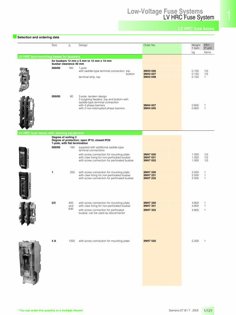
LV HRC fuse bases
1/121
LV HRC Fuse SystemLow-Voltage Fuse Systems 1
345678910
1213
Siemens ET B1 T · 2005
■ Selection and ordering data
Size In Design Order No. Weight PS*/P. unit1 item
kg Items
LV HRC bus-mounting bases for busbars for busbars 12 mm x 5 mm to 12 mm x 10 mm busbar clearance 40 mm
000/00 160 1-polewith saddle-type terminal connection, top 3NH3 036 0.150 1/3
bottom 3NH3 037 0.150 1/3terminal strip, top 3NH3 048 0.150 1
000/00 80 3-pole, tandem design3 outgoing feeders, top and bottom with saddle-type terminal connectionwith 4 phase barriers 3NH4 037 0.800 1with 2 non-interrupted phase barriers 3NH4 045 0.800 1
LV HRC fuse bases with slewing equipmentDegree of soiling 3 Degree of protection: open IP10, closed IP201-pole, with flat termination
000/00 160 supplied with additional saddle-typeterminal connections
with screw connection for mounting plate 3NH7 030 1.000 1/3with claw fixing for non-perforated busbar 3NH7 031 1.000 1/3with screw connection for perforated busbar 3NH7 032 1.000 1/3
1 250 with screw connection for mounting plate 3NH7 230 2.500 1with claw fixing for non-perforated busbar 3NH7 231 2.500 1with screw connection for perforated busbar 3NH7 232 2.500 1
2/3 400 and 630
with screw connection for mounting plate 3NH7 330 4.800 1with claw fixing for non-perforated busbar 3NH7 331 4.800 1
with screw connection for perforated busbar, can be used as disconnector
3NH7 332 4.800 1
4 A 1250 with screw connection for mounting plate 3NH7 520 5.200 1
* You can order this quantity or a multiple thereof.

LV HRC fuse bases
1/122
LV HRC Fuse SystemLow-Voltage Fuse Systems
Siemens ET B1 T · 2005
■ Selection and ordering data
Size Order No. Weight PS*/P. unit1 item
kg Items
Mounting parts for LV HRC fuse basesLV HRC contact cover
protection against contact for contact pieces 000/00 3NX3 105 0.013 20 3NX3 114 0.010 21 3NX3 106 0.027 2
2 3NX3 107 0.031 23 3NX3 108 0.038 2
LV HRC partitionsfor side-by-side mounting of LV HRC fuse basesand as end barrier for side-by-side arrangement
Type
3NH3 0/3NH4 0 000/00 3NX2 023 0.025 23NH3 1 0 3NX2 030 0.050 23NH3 2 1 3NX2 024 0.053 2
3NH3 3 2 3NX2 025 0.066 23NH3 4 3 3NX2 026 0.101 2
LV HRC protective cover IP2Xfor LV HRC fuse bases, size 000/001 and 3-pole 3NX3 115 0.039 1/10
LV HRC cover IP2Xfor LV HRC protective cover IP2X 3NX3 116 0.014 1/10
Mounting parts for LV HRC bus-mounting basesLV HRC contact covers for mounting onto contacts to ensure protection against contact
outgoing terminal 3NX3 105 0.013 2incoming terminal 3NX3 113 0.006 2
LV HRC phase barriers for 3NH3 0 LV HRC bus-mounting bases phase barrier 3NX2 027 0.017 2
end barrier 3NX2 028 0.020 2
for 3NH4 0 LV HRC bus-mounting base in tandem design 3NX2 031 0.050 2non-interrupted phase barrier
* You can order this quantity or a multiple thereof.

LV HRC fuse bases
1/123
LV HRC Fuse SystemLow-Voltage Fuse Systems 1
345678910
1213
Siemens ET B1 T · 2005
■ Selection and ordering data
Size Order No. Weight PS*/P. unit1 item
kg Items
Mounting parts for LV HRC fuses Fuse puller 000 ... 4for LV HRC fuse links
without sleeve 3NX1 013 0.280 1
with sleeve 3NX1 014 0.480 1
Isolating linkfor LV HRC fuse bases and fuse switch disconnectors
with insulated grip lugs
silver-plated 000/00 3NG1 002 0.080 1/60 3NG1 102 0.110 1/6
1 3NG1 202 0.170 1/32 3NG1 302 0.240 1/33 3NG1 402 0.290 1/3
with non-insulated grip lugs
tinned 4 3NG1 503 0.708 1/6nickel-plated 4a 3NG1 505 0.730 1/3
Fuse base cover
for LV HRC fuse bases 000/00 3NX1 003 0.050 3according to DIN 43620 1, 2, 3 3NX1 004 0.100 3red with yellow information label "power supply isolating point"
* You can order this quantity or a multiple thereof.

LV HRC fuse bases
1/124
LV HRC Fuse SystemLow-Voltage Fuse Systems
Siemens ET B1 T · 2005
■ Dimensional drawings
LV HRC fuse bases
1) Size 4 LV HRC fuse links are also screwed onto the base.
2) LV HRC bus-mounting bases are only connected on one side using terminals, the second connection is made through the bottom of the base.
1- and 3-pole
Size 000/00 to 3Size In Num-
ber of poles
Connection Type Dimensions
A w1 w2 h1 h2 d1 d2 d3
000/00 160 1 M8 plug connection 3NH3 0.. 30 34 102 122 24 40 60Saddle-type terminal connection
29
Flat termination 23
3 M8 plug connection 3NH4 0.. 30 102Saddle-type terminal connection
29
Flat termination 23
1 Saddle-type terminal connection
LV HRC bus mountingbase 2)
3NH3 0..
29 37 – 95 28 44 64
Terminal strip 26 102
0 160 1 Flat termination 3NH3 1.. 23 38 150 173 24 39 60Clamp-type terminal connection
30
Size 4 1) 1 250 1 M10 flat termination 3NH3 2.. 35 49 177 201 35 55 84Double busbar connection
3 M10 flat termination 3NH4 2.. 163
2 400 1 M10 flat termination 3NH3 3.. 35 49 202 226 35 55 90Double busbar connection
3 630 1 M12 flat termination 3NH3 4.. 35 49 212 241 35 55 101Double busbar connection
4 1250 1 M12 flat termination 3NH3 5.. 50 102 270 max. 307
51 1161) 144
4 A Can only be used in bases with slewing equipment
LV HRC bus-mounting base 2)
1-pole
������
� �
� �
��
��
� �
� �
� �
������� �
� �
� �
��
��
� �
� �
������
��
� �
� �
� �
� �
� �
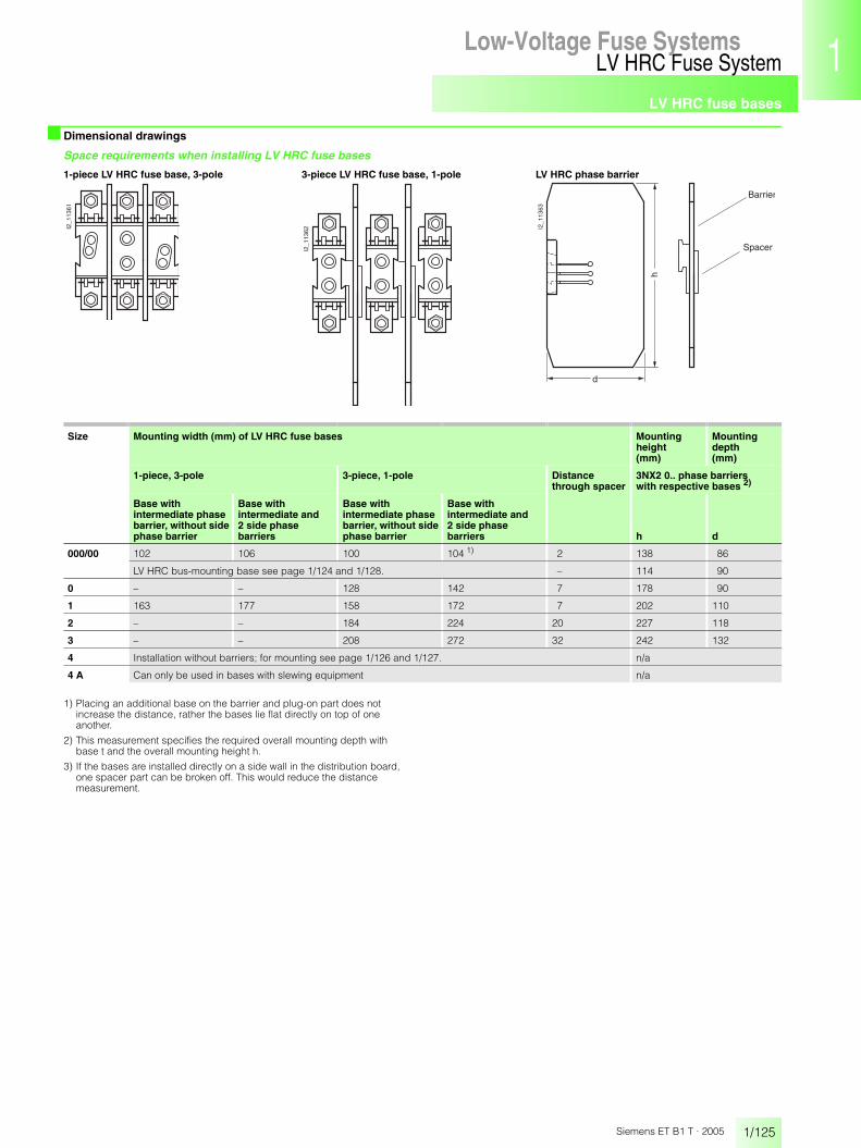
LV HRC fuse bases
1/125
LV HRC Fuse SystemLow-Voltage Fuse Systems 1
345678910
1213
Siemens ET B1 T · 2005
■ Dimensional drawings
Space requirements when installing LV HRC fuse bases
1) Placing an additional base on the barrier and plug-on part does not increase the distance, rather the bases lie flat directly on top of one another.
2) This measurement specifies the required overall mounting depth with base t and the overall mounting height h.
3) If the bases are installed directly on a side wall in the distribution board, one spacer part can be broken off. This would reduce the distance measurement.
1-piece LV HRC fuse base, 3-pole 3-piece LV HRC fuse base, 1-pole LV HRC phase barrier
Size Mounting width (mm) of LV HRC fuse bases Mounting height (mm)
Mounting depth(mm)
1-piece, 3-pole 3-piece, 1-pole Distance through spacer
3NX2 0.. phase barriers with respective bases 2)
Base with intermediate phase barrier, without side phase barrier
Base with intermediate and 2 side phase barriers
Base with intermediate phase barrier, without side phase barrier
Base with intermediate and 2 side phase barriers h d
000/00 102 106 100 104 1) 2 138 86
LV HRC bus-mounting base see page 1/124 and 1/128. – 114 90
0 – – 128 142 7 178 90
1 163 177 158 172 7 202 110
2 – – 184 224 20 227 118
3 – – 208 272 32 242 132
4 Installation without barriers; for mounting see page 1/126 and 1/127. n/a
4 A Can only be used in bases with slewing equipment n/a
I2_1
1361
I2_1
1362 I2
_113
63
Barrier
Spacer
h
d

LV HRC fuse bases
1/126
LV HRC Fuse SystemLow-Voltage Fuse Systems
Siemens ET B1 T · 2005
■ Dimensional drawings
Drill hole dimensions for base plate mountingLV HRC bases 1-poleSizes000/00 and 0
Sizes 1 to 3
Size 4 Size Type Dimensions
w1 w2 h1 h2 l
000/00 3NH3 0.. 17 – 48 25.5 7.5
0 3NH3 1.. 19 – 74 25 7.5
1 3NH3 2.. 9 31 88 26 10.5
2 3NH3 3.. 9 31 100 26 10.5
3 3NH3 4.. 9 31 108 26 10.5
4 3NH3 530 36 30 141 25 13
LV HRC bases 3-poleSize 000/00 Size 1
Size Type Dimensions
w1 w2 h1 h2 l
000/00 3NH4 0.. 15 70 46 – 7.5
1 3NH4 230 26 110.5 88 25 10
������
�
� �
��
��
��
������
�
��
� �
��
��
� � � �
������
�
� � � �� �
��
��
��
������
�
� � � �� �
��
��
������
�
� � � �� �
��
��
��

LV HRC fuse bases
1/127
LV HRC Fuse SystemLow-Voltage Fuse Systems 1
345678910
1213
Siemens ET B1 T · 2005
■ Dimensional drawings
Drill hole dimensions for base plate mountingLV HRC bases, 3-piece, 1-poleSizes 000/00 and 0
Size Type Dimensions
w1 w2 w3 h1 h2 l
000/00 3NH3 0.. 17 34 – 48 25.5 7.5
0 3NH3 1.. 17 41 – 74 25 7.5
1 3NH3 2.. 9 31 25 88 26 10.5
2 3NH3 3.. 9 31 38 100 26 10.5
3 3NH3 4.. 9 31 50 108 26 10.5
4 3NH3 530 36 30 95 141 25 13
������
�
� �
��
��
��
� �� �� �
Sizes 1, 2 and 3
������
�
� �� �� �� �
��
� �
��
��
� �
Size 4
Note:These LV HRC bases are mounted without phase barriers. A minimum clearance of a = 25 mm is required.
������
��
�
� � � �
��
��
��
� �� � � �� �� �

LV HRC fuse bases
1/128
LV HRC Fuse SystemLow-Voltage Fuse Systems
Siemens ET B1 T · 2005
■ Dimensional drawings
LV HRC bus-mounting bases in tandem design
LV HRC bases with slewing equipment, 1-pole
Busbar center-to-center clearance 40 mm3NH4 037, 3NH4 045
Space requirements for3-piece, 1-pole LV HRC bus-mounting bases, staggered
I2_0
6498
a33 33107
213,
5
4491
28
230
82
I2_1
1364
71
38
Sad
dle-
type
term
inal
con
nect
ion:
175
Ter
min
al s
trip
: 182
Sizes 000/00 to 4a Drill hole dimensions for base plate mounting
Size 000/00
Sizes1 and 2/3
Size 4a
I2_1
1357
ao
d
eb
c
ln
m
����
���
�
�
���� ��
���
����
�
��
�
���� ��
�
h2
f
h1 h1
� kg
I2_1
1360
g
Size In Type Dimensions
A a b c d e f g h1 h2 k l m n o p
000/00 160 3NH7 03. 44 149 45 88.5 22.5 79 – 9.5 25 7 120 17 18 200 20
1 250 3NH7 23. 68 230 68 123.5 23 102.5 25 19 30 10.5 177 25 40 300 25
2/3 630 3NH7 33. 90 270 96 153.5 15.5 122.5 25 30 30 10.5 220.5 30.5 35 350 40
4 A 1250 3NH7 520 116 350 154.5 217.5 69 170 30 31.5 45 13 270 40 26 440 50

LV HRC fuse bases
1/129
LV HRC Fuse SystemLow-Voltage Fuse Systems 1
345678910
1213
Siemens ET B1 T · 2005
■ Dimensional drawings
Mounting parts for LV HRC fuse bases
Mounting parts for LV HRC bus-mounting bases
LV HRC contact covers
Sizes 000/00 to 3, 3NX3 10
Size Type Dimensions
a b c d e
000/00 3NX3 105 38 47.5 34 11.5 30
1 3NX3 106 61.5 57 42.5 35 46
2 3NX3 107 74 65 51 35 46
3 3NX3 108 81.5 77.5 57.5 35 46
3NX3 115 LV HRC protection cover, with 3NX3 116 LV HRC shrouding cover
Size 000/00, degree of protection IP2X
I2_1
1365a
e
d
bc
�� ��
���
��
����
����
LV HRC partitions
Size 000/00 Sizes 0 to 33NX3 023 3NX2 030, 3NX2 024 to 3NX2 026
Size Type Dimensions
a b c d
0 3NX2 030 87.6 178.5 7.7 12.3
1 3NX2 024 107.3 202.5 7.7 12.3
2 3NX2 025 115.3 227.5 14.2 25.1
3 3NX2 026 129.8 242 20.2 37.2
��������
���
��������
��
���
����
�
���
�
�������
�
�
�
���
���
���
LV HRC contact covers
for 1-pole design and tandem design,3NX3 105
3-pole,3NX3 113
LV HRC partitions
3NX2 027 3NX2 028 3NX2 031 non-interrupted, phase barrier end barrier for LV HRC bases in tandem design
I2_1
1367
3047,5
34
38
5030
I2_11368
11,5
114
82
I2_0
6499
a
113,
5
86,5
I2_06502a
230
81,5
I2_0
6684
a
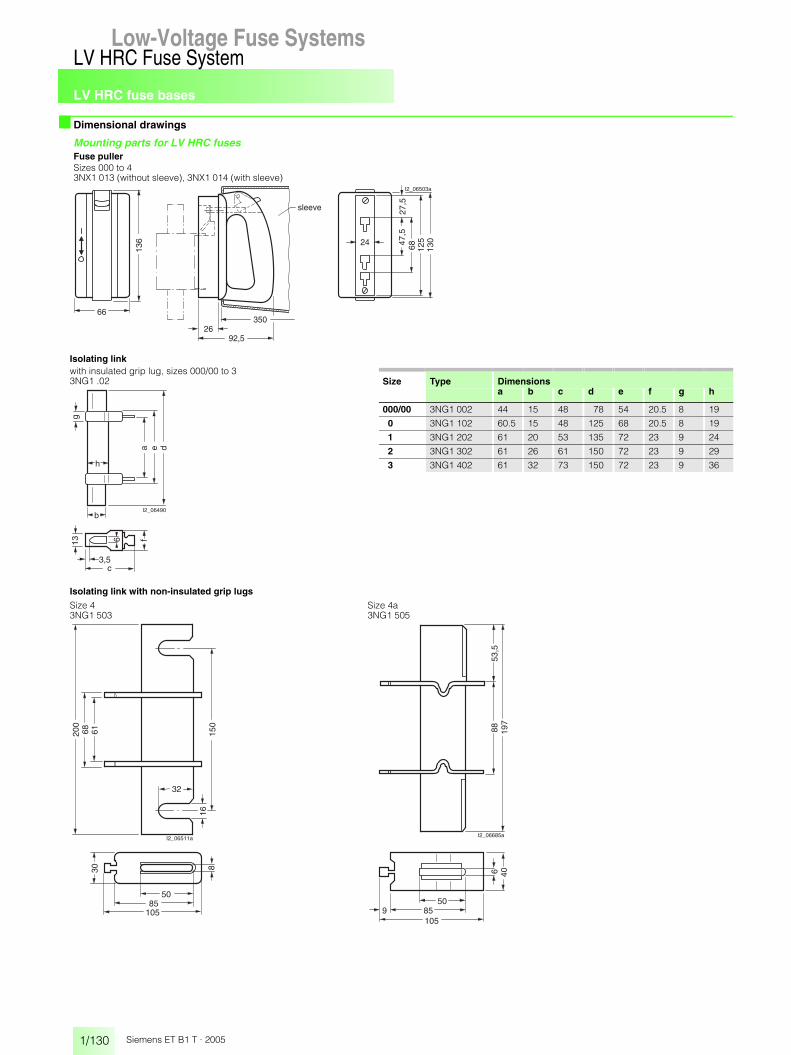
LV HRC fuse bases
1/130
LV HRC Fuse SystemLow-Voltage Fuse Systems
Siemens ET B1 T · 2005
■ Dimensional drawings
Mounting parts for LV HRC fusesFuse puller Sizes 000 to 43NX1 013 (without sleeve), 3NX1 014 (with sleeve)
Isolating linkwith insulated grip lug, sizes 000/00 to 33NG1 .02 Size Type Dimensions
a b c d e f g h
000/00 3NG1 002 44 15 48 78 54 20.5 8 19
0 3NG1 102 60.5 15 48 125 68 20.5 8 19
1 3NG1 202 61 20 53 135 72 23 9 24
2 3NG1 302 61 26 61 150 72 23 9 29
3 3NG1 402 61 32 73 150 72 23 9 36
Isolating link with non-insulated grip lugs
Size 4 Size 4a3NG1 503 3NG1 505
27,5
47,5
68 125
13024
66
136
350
92,526
I2_06503a
sleeve
a e d
I2_06490
g
b
h
c3,5
13 6 f
I2_06511a
8
68200
30
150
16
61
32
5085
10550
85105
9
6 4053
,588 19
7
I2_06685a

LV HRC signal detectors
1/131
LV HRC Fuse SystemLow-Voltage Fuse Systems 1
345678910
1213
Siemens ET B1 T · 2005
■ Overview The signal detector supports monitoring of LV HRC fuse links of 10 A or higher. The signal detector can be mounted onto any LV HRC fuse link of size 000 to 4 with non-insulated grip lugs.The signal detector link is connected in parallel to the LV HRC fuse link via spring contacts.In the event of a fault, the LV HRC fuse link is released simultaneous-ly with the LV HRC fuse signaling link. A tripping pin in the LV HRC fuse signaling link switches a microswitch for 250 V AC/5 A.In order to replace the signal detector link, the signal detector is removed from the LV HRC fuse link. It is then off circuit.
■ Selection and ordering data
■ Dimensional drawings
$ LV HRC fuse link% Signal detector& Microswitch( Spring contact) Flap* Signal detector link
�
��
������
�
�
Size Order No. Weight PS*/P. unit1 item
kg Items
LV HRC signal detector 000 ... 4 3NX1 021 0.036 1/4for LV HRC fuse links with non-insulated grip lugs • rated voltage up to 690 V AC/600 V DC• contact: microswitch 250 V AC, 6 A• connection: flat connector 2.3 mm ... 0.5 mm
Signal detector link 000 ... 4rated voltage up to 690 V AC/600 V DCresponse value > 9 V; 2.5 A; for standard applications
3NX1 022 0.015 1/12
response value > 2 V; 7 A; only for meshed systems 3NX1 023 0.015 1/12
� � �
LV HRC signal detector Signal detector link
3NX1 021 3NX1 022, 3NX1 023
115
40
I2_0
7856
a
2515
I2_0
7857
a
11
7
66
* You can order this quantity or a multiple thereof.

LV HRC fuse switch disconnectors
1/132
LV HRC Fuse SystemLow-Voltage Fuse Systems
Siemens ET B1 T · 2005
Low-Voltage Fuse Systems
■ Application
SENTRIC 3NP4 and 3NP5 fuse switch disconnectors are switch-ing devices for the occasional manual switching/isolating of loads and distribution boards. They are able to switch on, control and switch off the specified rated current (including a specific overload).
With the SENTRIC 3NP4 and 3NP5 fuse switch disconnectors, all poles of downstream electric loads can be safely discon-nected from the system under load.
The SENTRIC 3NP4 and 3NP5 fuse switch disconnectors are ideal for mounting on and in distribution boards (e.g. ALPHA, SIKUS), meter cabinets (e.g. ALPHA 400-ZS) and molded-plas-tic distribution system, such as SENTRIC 8HP.
The ability to mount them on a range of different busbar systems allows their very diverse implementation in switchgear cabinet and control engineering.
The sizes SENTRIC 3NP4 LV HRC 000 2) and LV HRC 00 can be snapped onto 35 mm mounting rails and are ideal for combining with other switching devices e.g. in capacitor modules for p.f. compensation.
SENTRIC 3NP4 and 3NP5 fuse switch disconnectors
Used together with semiconductor fuses (e.g. SITOR), they provide effective protection for frequency converters and soft starters.
SENTRIC NP fuse switch disconnectors
3NP40 10 3NP40 70 3NP52 with open fuse carrier
The SENTRIC 3NP4 and 3NP5 fuse switch disconnectors are climate proof and comply with the standards IEC 60947-1, IEC 60947-3 and EN 60947-1, EN 60947-3.
For use in heavily sulfurous atmospheres, the SENTRIC 3NP5 series, as well as the 3NP40 1 and 3NP40 7 versions, are avail-able as tinned models (delivery on request).
The SENTRIC 3NP5 fuse switch disconnector series also com-plies with the standard BS 5419 and is approved for use in ship-board systems. 1)
All SENTRIC 3NP4 and 3NP5 fuse switch disconnectors can be sealed as standard (or can be sealed through accessories).
1) Always use approved fuse links.
2) Corresponds to fuse size LV HRC 000 (LV HRC 00C) or LV HRC 00 withreduced dimensions; maximum width 21 mm according to IEC 60269-2-1 and DIN 43620.
■ Design
The SENTRIC 3NP4 and 3NP5 fuse switch disconnectors com-prise a base and a removable fuse carrier with view and measur-ing window.
The base contains integral lyra contacts, arcing chambers and terminal fittings. The fuse links/isolating links are contained in the fuse carrier.
The fuse links can be replaced without tools.
The three conducting paths in the base and the fuse links in the fuse carrier are separated by partitions that overlap when open-ing and closing the device.
This type of failsafe protection is called "complete compartmen-talization" and effectively prevents phase arcing.
SENTRIC 3NP5 fuse switch disconnectors are also equipped with locating springs, which are fitted to the side of the base. These enable the "high speed closing" of devices, regardless of the actuation speed of the operator.
The SENTRIC 3NP4 and 3NP5 fuse switch disconnectors are used with LV HRC fuses of sizes LV HRC 000 to LV HRC 3 ac-cording to IEC 60269-2-1, DIN VDE 0636-201 and DIN 43620. SITOR semiconductor fuses can continue to be used for a wide range of applications.
For more detailed information, please refer to the instruction manual for the SENTRIC 3NP4 and 3NP5 fuse switch disconnec-tors.
Auxiliary switches
The SENTRIC 3NP4 and 3NP5 fuse switch disconnectors also be retrofitted with auxiliary switches for indicating the switching position of the fuse carrier.
One switching element (1 CO) can be mounted on SENTRIC 3NP4 fuse switch disconnectors size LV HRC 000 and two switching elements (1 CO) on sizes LV HRC 00 to LV HRC 3 respectively.
SENTRIC 3NP5 fuse switch disconnectors can also be delivered with a 2-pole auxiliary switch (1 NO + 1 NC) if required. The ver-sion with fuse monitoring is fitted with this auxiliary switch as standard.

LV HRC fuse switch disconnectors
1/133
LV HRC Fuse SystemLow-Voltage Fuse Systems 1
345678910
1213
Siemens ET B1 T · 2005
■ Function
Fuse monitoring using the SIRIUS circuit-breaker
For fuse monitoring, a SIRIUS circuit-breaker is factory-fitted and hard-wired to the fuse carrier of the SENTRIC 3NP4 and 3NP5 fuse switch disconnectors.
If the fuse carrier is closed, the three conducting paths of the SIRIUS circuit-breaker are switched in parallel to the fuse links to be monitored. If the fuse carrier is open, all main conducting paths of the circuit-breaker are off circuit.
The internal resistance of the circuit-breaker is great enough not to impair the protective function of the monitored fuse links.
Failure of a fuse will trigger the circuit-breaker. The auxiliary switch of the circuit-breaker can be used for indication purposes or to disconnect the main circuit, e.g. through a contactor.
The signal lead for the SENTRIC 3NP4 fuse switch-disconnector size LV HRC 00 needs to be ordered separately. Sizes LV HRC 1 to LV HRC 3 are connected using flat connectors.
Delivery of the SENTRIC 3NP5 fuse switch disconnectors in-cludes the signal lead, complete with connector.
SIRIUS circuit-breakers cannot be used for fuse monitoring in branch circuits with circuit-breakers where a fault may result in > 220 V DC feedback.
In the case of parallel cables and meshed systems, only a voltage difference of > 24 V at the switch will trigger the circuit-breaker.
Electronic fuse monitors
For electronic fuse monitoring, the EF monitor is factory-fitted and hard-wired to the fuse carrier of SENTRIC 3NP5 fuse switch-disconnectors.
The EF monitor works independently of any loads. Failure of a fuse can be relayed to a control room through integrated auxil-iary switches (2 NO + 1 NC) by means of a centralized fault in-dication or used to isolate the load through e.g. a contactor
Actuation of the auxiliary switch depends on the ESÜ version. Version "A" stands for "open-circuit principle", version "R" for closed-circuit principle" (see block diagram).
If a fuse is tripped, a green LED signal flashes (general fault) and the location of the failed fuse is indicated by a red LED. Using more than one device facilitates identification of the affected branch circuit.
The EF monitor is automatically reset to the standby position once the faulty fuses are replaced. This state is indicated visually by the status display (green LED).
The Ef monitor is also suitable for use in industrial systems badly afflicted by harmonics.

LV HRC fuse switch disconnectors
1/134
LV HRC Fuse SystemLow-Voltage Fuse Systems
Siemens ET B1 T · 2005
■ Technical specifications
1) 125/160 A only with 3NY1 236 supply terminals and with 3NY1 822 (125 A) and 3NY1 824 (160 A) 21 mm-wide fuse links; see accessories.
2) When switching without load (AC-20 B, DC-20 B), direct voltages up to 690 V DC can be applied.
3) For safety monitoring max. 690 V.
4) For degree of soiling 2, the disconnectors can be used up to 1000 V AC-20 B, DC-20 B (switching without load).
5) Conducting paths in series: 3 for 3NP40; 2 for 3NP42, 3NP43 and 3NP44.
Type 3NP40 1 3NP40 7 3NP42 7 3NP43 7 3NP44 7
Standards IEC 60947-1, IEC 60947-3, EN 60947-1, EN 60947-3
Rated continuous current Iu A 160 1) 160 250 400 630for fuse links acc. to DIN 43620 Size 00C/000 00 1 and 0 2 and 1 3 and 2
Conventional free air thermal current Ith A 160 1) 160 250 400 630
Rated operational voltage Ue50 Hz/60 Hz AC V 690 690DC V 220
(3 current paths connected in series)440 (2 current paths conn. in series)
Rated insulation voltage Ui V 690 690 800 3) 800 3) 800 3)
Rated impulse voltage Uimp kV 6 6 6 6 6
Rated conditional short-circuit current with fuses (by fast switch on)
with fuse links rated current) Size/A 000/100 (35) 00/160 1/250 2/400 3/630at 400 V AC (690 V) kA (rms value) 50 (50) 50 50 50 50
maximum permissible let-through I2t value kA2s 56 (7.8) 158 551 1515 4340
permissible let-through current of the fuse kA (peak value) 11 (5) 15 25 35 55
Short-circuit strength with fuses (with closed disconnector)
with fuse linksrated current Size/A 000/100 00/160 1/250 2/400 3/630at 690 V kA (rms value) 100 50 50 50 50
permissible let-through current of the fuse kA (peak value) 15 15 25 35 55
Rated making and breaking capacity (incoming supply from top or bottom)
at 400 V AC, with fuse links or isolating links
Size 000 00 1 2 3
rated breaking current Ic (p.f. = 0.35) A (rms value) 800 (p.f. = 0.45) 800 2000 3200 5040rated operational current Ie forAC-21B, AC-22B AC-23B
AA
160100
160100
250250
400400
630630
at 500 V AC, with fuse links or isolating links
Size 000 00 1 2 3
rated breaking current Ic (p.f. = 0.35) A (rms value) 320 (p.f. = 0.45) 320 750 1200 1890rated operational current Ie forAC-21B, AC-22B AC-23B
AAA
16010040
16010040
250250–
400400–
630630–
at 690 V AC, with fuse links or isolating links
Size 000 00 1 2 3
rated breaking current Ic (p.f. = 0.35) A (rms value) 200/240 (p.f. = 0.45/0.95)
200/240 (p.f. = 0.45/0.95)
375 600 945
rated operational current Ie forAC-21B, AC-22B AC-23B
AAA
1605025
1605025
250––
400––
630––
at 220 V/240 V DC, with fuse links 2)4)5) or isolating links
Size 000 00 1 2 3
rated operational current Ie at220 V DC-23B/DC-21B440 V DC-21B
AA
80/160–
80/160–
–250
–400
–630

LV HRC fuse switch disconnectors
1/135
LV HRC Fuse SystemLow-Voltage Fuse Systems 1
345678910
1213
Siemens ET B1 T · 2005
■ Technical specifications
1) Only with isolating links; otherwise, please observe specifications of fuse manufacturer.
Type 3NP40 1 3NP40 7 3NP42 7 3NP43 7 3NP44 7
Standards IEC 60947-1, IEC 60947-3, EN 60947-1, EN 60947-3
Capacitor switching capacity
at 400 V ACcapacitor rating kvar 50 50 – – –rated current In A 72 72 – – –
at 525 V ACcapacitor rating kvar 50 50 – – –rated current In A 55 55 – – –
Permissible ambient temperature °C –25 ... +55 1) for operation, –50 ... +80 for storage
Mechanical lifetime Operating cycles
2000 2000 1600 1000 1000
Degree of protection (operator side)
without insulating cover/cable lug cover IP00 (3NP40 with box terminal and properly connected conductors: IP20)
with insulating cover/cable lug cover IP30 (switch closed), IP20 (switch open)
Power dissipation of switch at Ith (plus power dissipation of fuse links)
without busbar adapter W 4.5 (at 100 A) 10 15 30 47
with busbar adapter W 8.5 (at 100 A) 20 47 83 127
Main conductor connection
flat termination for lug, max. conductor cross-section (stranded)
mm2 – up to 2 × 70(M8)
up to 150(M10)
up to 240(M10)
up to 2 × 240(M12)
box terminal/terminal (finely stranded with end sleeve)
mm2 1.5 ... 50 (35) 2.5 ... 70 (50) 70 ... 150 120 ... 240 150 ... 300
power rail (width × thickness) mm – 22 × 5 22 ... 30 × 5 ... 10 22 ... 30 × 5 ... 10 25 ... 40 × 5 ... 10
laminated Cu strips, non-perforated in terminals (width × thickness)
mm 8 × 8 up to 9 × 8 up to 16 × 8 up to 20 × 10 up to 24 × 10
Tightening torque for terminal screws
for flat termination Nm – 10 ... 12 25 25 30
with SIGUT box terminal/terminal Nm 3 ... 3.5 8 ... 10 6 8 8
Auxiliary switch 1 CO (accessories)
3NY3 035 50 Hz/60 Hz to 230 V ACrated operational current Ie for AC-14 A 0.25 (Ith = 5 A), at 24 V DC: Ie = 0.45 A; flat connectors according to DIN 46244: A 2.8 × 0.5
3NY3 030 50 Hz/60 Hz to 230 V ACrated operational current Ie for AC-13 A 0.1 (Ith = 0.1 A); quick-connect terminal according to DIN 46245: A 2.8 – 1
Permissible mounting position vertical or horizontal installation (no reduction of specified switching capacity)

LV HRC fuse switch disconnectors
1/136
LV HRC Fuse SystemLow-Voltage Fuse Systems
Siemens ET B1 T · 2005
■ Technical specifications
1) Ui = 1000 V is possible when maintaining pollution degree 2 (instead of 3).
2) Rated making and breaking current according to IEC 60947-3:Rated making current I = 10 × Ie (AC-23); 3 × Ie (AC-22); 1.5 × Ie (AC-21);Rated breaking current Ie = 8 × Ie (AC-23); 3 × Ie (AC-22); 1.5 × Ie (AC-21).
3) When electronic fuse monitors are used, infeed must be from the top.
4) Use silver-plated isolating links.
Type 3NP50 3NP52 3NP53 3NP54
Standards IEC 60947-1, IEC 60947-3, EN 60947-1, EN 60947-3
Rated continuous current Iu A 160 250 400 630 for fuse links acc. to DIN 43620 Size 00 1 and 0 2 and 1 3 and 2(when using semiconductor fuse links, reduction of rated current required)
Conventional free air thermal current Ith A 160 250 400 630
Rated operational voltage Ue50 Hz/60 Hz AC V 690DC V 440 (3 conducting paths in series),
220 (2 conducting paths in series and for fuse monitoring through 3RV)
Rated insulation voltage Ui V 690 1) 690 1) 690 1) 690 1)
Rated impulse voltage Uimp kV 6 6 6 6
Rated conditional short-circuit current with fuses (by fast switch on)
with fuse linksrated current Size/A 00/160 1/250 2/400 3/630at 500 V AC kA (rms value) 50 50 50 50
permissible let-through current of the fuses kA (peak value) 15 25 40 50
Short-circuit strength with fuses (with closed disconnector)
with fuse linksrated current Size/A 00/160 1/250 2/400 3/630at 500 V AC kA (rms value) 100 100 50 50
maximum permissible let-through I2t value kA2s 223 780 2150 5400
permissible let-through current of the fuses kA (peak value) 23 32 40 60
Rated short-circuit making capacitywith isolating links 2) Size 00 1 2 3at 500 V AC kA (peak value) 6 17 17 17
Rated making and breaking capacity 2) (incoming supply from top or bottom) 3)
at 400 V AC, with fuse links Size 00 1 0 2 1 3 2breaking current Ic (p.f. = 0.35) A (rms value) 1600 2500 1600 4000 2500 5040 4000rated operational current Ie for AC-21B, AC-22B, AC-23B A 160 250 160 400 250 630 400
at 500 V AC, with fuse linksbreaking current Ic (p.f. = 0.35) A (rms value) 1300 2500 1600 4000 2500 5040 4000rated operational current Ie for AC-21B, AC-22B, AC-23B A 160 250 160 400 250 400 400
at 690 V AC, with fuse linksbreaking current Ic (p.f. = 0.35) A (rms value) 800 1280 1000 2520 1600 3200 2520rated operational current Ie forAC-21B, AC-22B AC-23B
AA
160100
250160
160125
400315
250200
630400
400315
at 220 V DC, with fuse linksbreaking current Ic (L/R = 15 ms) A 640 1000 640 1600 1600 2520 1600rated operational current Ie for DC-23B A 160 250 160 250 250 400 400
Switching capacity with isolating links 4) (incoming supply from top or bottom) 4)
at 400 V AC, with isolating links Size 00 1 2 3breaking current Ic (p.f. = 0.35) A (rms value) 1600 2500 2500 4000rated operational current Ie forAC-21B, AC-22B AC-23B
AA
160160
250250
400315
630500
at 500 V AC, with isolating linksbreaking current Ic (p.f. = 0.35) A (rms value) 1300 2500 2500 4000rated operational current Ie forAC-21B, AC-22B AC-23B
AA
160160
250250
400315
630500
at 690 V AC, with isolating linksbreaking current Ic (p.f. = 0.35) A (rms value) 800 1280 1600 2520rated operational current Ie forAC-21B, AC-22B AC-23B
AA
160100
250160
400200
630315
at 220 V DC, with isolating linksbreaking current Ic (L/R = 15 ms) A 640 1000 1600 1600rated operational current Ie for DC-23B A 160 200 400 400
Switching capacity for horizontal installation up to 690 V AC-22B
no reduction of the specified switching capacity (values for 230 to 690 V AC on request)

LV HRC fuse switch disconnectors
1/137
LV HRC Fuse SystemLow-Voltage Fuse Systems 1
345678910
1213
Siemens ET B1 T · 2005
■ Technical specifications
1) When using isolating links. If using fuse links, please observe specifications of fuse manufacturer.
2) For 3NP52 with clamp connection, degree of protection IP10.
3) With busbar adapter.
Type 3NP50 3NP52 3NP53 3NP54
Capacitor switching capacity
at 400 V ACcapacitor rating kvar 80 90 150 250rated current In A 116 130 216 361
at 525 V ACcapacitor rating kvar 100 125 200 300rated current In A 110 137 220 330
Permissible ambient temperature °C – 25 ... + 55 for operation 1), – 50 ... + 80 for storage
Mechanical lifetime Operating cycles
1600
Degree of protection
without molded-plastic cover IP00 2)
with insulating cover andclosed fuse carrier on the operator side IP30with open handle unit IP10
Power loss of the switch at Ith(plus power dissipation of the fuse links) without busbar adapter W 7.8 (16.3) 3) 7.5 15 39
Main conductor connection
cable lug, max. conductor cross-section (stranded) mm2 2.5 ... 120 6 ... 150 6 ... 240 6 ... 2 × 240busbar mm 16 ... 22 22 ... 30 22 ... 30 22 ... 30clamp connections mm2 2.5 ... 50 35 ... 120 – –
Tightening torque
with cable lug Nm 18 ... 22 25 ... 30 25 ... 30 25 ... 30with power rail Nm 18 ... 22 25 ... 30 25 ... 30 25 ... 30with clamp connection Nm 9 ... 11 5 ... 6 – –
Terminal screws
with cable lug M 8 M 10 M 10 M 10with power rail M 8 M 10 M 10 M 10with clamp connection M 8 2 × M 6 – –
Ground terminal
lug according to DIN 46234 mm2 – 2.5 ... 70 6 ... 2 × 70 6 ... 2 × 120busbar mm – 25 25 30terminal screws – M 8 M 10 M 10
Auxiliary switch 1 NO + 1 NC (accessories) (the same voltage potential must be applied to both NO and NC contact)
at 50 Hz/60 Hz to 400 V AC, rated operational current Ie at AC-12/AC-15 A
A 16/6
flat connector (DIN 46244) A 6.3–0.8
Permissible mounting position vertical or horizontal installation (switching capacity is sometimes reduced with horizontal installation)
Fuse monitor with 3RV circuit-breaker see circuit-breaker
Electronic fuse monitoring
rated voltage 50 Hz/60 Hz AC V 400 –15% ... 500 V +10%, self-powered (incoming supply from top)
max. making current A 20continuous current A 5breaking current A 5
switching capacity VA 1000
short-circuit strength (1 ms) A 100response time s < 1temperature range (operation) °C –10 ... +75plug-in connectors/connections 6-pole
minimum potential difference requiredbetween top and bottom connections of the switch (e.g. for use in meshed systems)
V > 10
Signal contact for electronic fuse monitoring
2 NO + 1 NC
rated operational current Ieat 250 V, DC-13 A 0.27at 240 V, AC-15 A 1.5
rated free air thermal current Ith A 5

LV HRC fuse switch disconnectorsfor power distribution
1/138
LV HRC Fuse SystemLow-Voltage Fuse Systems
Siemens ET B1 T · 2005 * You can order this quantity or a multiple thereof.
■ Selection and ordering data
For all fuse switch disconnectors with flat terminations, use the rele-vant cable lug covers (3NY7 101 to 3NY7 141) in order to ensure protection against finger touch according to VBG4, see accessories.1) See LV HRC fuse links
2) Use silver-plated isolating links.
3) 125/160 A only possible with 3NY1 822 (125 A) and 3NY1 824 (160 A) 21 mm fuse links, see accessories.
4) Corresponds to size 00 with maximum width 21 mm (according to IEC 60269-2-1 and DIN 43620).
5) For mounting on 5 mm thick busbars, a bar thickness compensation is required for 3NP42 and 3NP43, see accessories. 3NP44 can only be mounted on 10 mm thick busbars!
6) No further cover required for 3NP40 with box terminal.
Rateduninter-ruptedcurrent Iu
A
Connection type (double-ended) For fuse linksaccording to DIN 43620 1)
Size
For isolating links 2)
Degree of protection IP00, without fuse links, without isolating links, with terminal screws
Weight PS*/P. unitConnection for conductor
cross-section
1 item
mm2
Order No.
kg Items
for mounting and installation
3NP40 10
3NP40 70
3NP42 70
up to 160 A, also clip-on for mounting rail
160 3) Box terminal 1.5–50 000 4) 00 3NP40 10–0CH01 0.512 1
160 Flat termination up to 2 × 70 (M 8) 00 and 000 00 3NP40 70–0CA01 0.749 1Box terminal 2.5–70 or 2 × 2.5-16 3NP40 70–0CH01 0.800 1
250 Flat termination up to 150 (M 10) 1 and 0 1 and 0 3NP42 70–0CA01 2.430 1
400 Flat termination up to 240 (M 10) 2 and 1 2 and 1 3NP43 70–0CA01 3.610 1
630 Flat termination up to 2 × 240 (M 12) 3 and 2 3 and 2 3NP44 70–0CA01 4.980 1
for snapping onto busbar system, busbar center-to-center clearance 40 mmRails of width 12 mm or 15 mm and thickness 5 mm or 10 mm 5)
• with adapter, deep, e.g. for installation in ALPHA meter cabinets (ALPHA 400-ZS) and ALPHA distribution boards (STAB/SIKUS)
160 3) Box terminal 1.5–50• Connection, top 000 4) 00 3NP40 15–0CK01 0.952 1• Connection, bottom 3NP40 15–0CJ01 0.970 1
160 Flat termination up to 2 × 70 (M 8)• Connection, top 00 and 000 00 3NP40 75–0CE01 1.210 1• Connection, bottom 3NP40 75–0CF01 1.240 1
Box terminal 2.5–70 or 2 × 2.5-16• Connection, top 00 and 000 00 3NP40 75–0CK01 1.290 1• Connection, bottom 3NP40 75–0CJ01 1.270 1
• with adapter, flat, according to DIN 43620 Part 6, for general applications and ALPHA distribution boards (STAB/SIKUS)
160 3) Box terminal 1.5–50• Connection, top 000 4) 00 3NP40 15–1CK01 0.892 1• Connection, bottom 3NP40 15–1CJ01 0.888 1
160 Flat termination up to 2 × 70 (M 8)• Connection, top 00 and 000 00 and 000 3NP40 75–1CE01 1.180 1• Connection, bottom 3NP40 75–1CF01 1.180 1
Box terminal 2.5–70 OR 2 × 2.5-16• Connection, top 00 and 000 00 and 000 3NP40 75–1CK01 1.260 1• Connection, bottom 3NP40 75–1CJ01 1.210 1
250 Flat termination up to 240 (M 10)• Connection bottom
or top1 and 0 1 and 0 3NP42 75–1CG01 3.710 1
for snapping onto busbar system, busbar center-to-center clearance 60 mm
3NP40 16
3NP42 76
Rails of width 12 mm to 30 mm and thickness 5 mm or 10 mm 5) flat, T and I profiles, as well as on Rittal PLS systems.
160 3) Box terminal 6) 1.5–50• Connection, top 000 4) 00 3NP40 16–1CK01 0.916 1• Connection, bottom 3NP40 16–1CJ01 0.950 1
160 Flat termination up to 2 × 70 (M 8)• Connection, top 00 and 000 00 3NP40 76–1CE01 1.200 1• Connection, bottom 3NP40 76–1CF01 1.200 1
Box terminal 6) 2.5–70 OR 2 × 2.5-16• Connection, top 00 and 000 00 3NP40 76–1CK01 1.290 1• Connection, bottom 3NP40 76–1CJ01 1.240 1
250 Flat termination up to 150 (M 10)• Connection,
bottom or top1 and 0 1 and 0 3NP42 76–1CG01 3.710 1
400 Flat termination up to 240 (M 10)• Connection,
bottom or top2 and 1 2 and 1 3NP43 76–1CG01 5.440 1
630 Flat termination up to 2 × 240 (M 12)• Connection,
bottom or top3 and 2 3 and 2 3NP44 76–1CG01 7.680 1

LV HRC fuse switch disconnectorsfor power distribution
1/139
LV HRC Fuse SystemLow-Voltage Fuse Systems 1
345678910
1213
Siemens ET B1 T · 2005
■ Selection and ordering datawith fuse monitoring through SIRIUS circuit-breaker 1) 2)
For all fuse switch disconnectors with flat terminations, use the rele-vant cable lug covers (3NY7 101 to 3NY7 141) in order to ensure protection against finger touch according to VBG4, see accessories.1) SIRIUS circuit-breaker as standard with auxiliary switch 1 NO+ 1 NC.
On request 3NP40 7 also available with auxiliary switch 2 NO or 2 NC.
2) For 3NP40 7 with output socket for auxiliary switch, the signal lead must be ordered separately, see accessories.For 3NP41 to 3NP44, the auxiliary switch must be connected through the flat termination 2.8 mm × 0.5 mm according to DIN 46244-A.
3) See LV HRC fuse links
4) Use silver-plated isolating links.
5) For mounting on 5 mm thick busbars, a bar thickness compensation is required for 3NP42 and 3NP43, see accessories. 3NP44 can only be mounted on 10 mm thick busbars!
Rateduninter-ruptedcurrent Iu
Connection type (double-ended) For fuse linksaccording to DIN 43620 3)
For isolating links 4)
Degree of protection IP00, without fuse links, without isolating links, with terminal screws
Weight PS*/P. unitConnection for conductor
cross-section
1 item
A mm2 Size SizeOrder No.
kg Items
for mounting and installationup to 160 A, also clip-on for mounting rail
160 Flat termination up to 2 × 70 (M 8) 00 and 000 00 3NP40 70–0FA01 1.270 1Box terminal 2.5–70 or 2 × 2.5-16 3NP40 70–0FH01 1.350 1
250 Flat termination up to 150 (M 10) 1 and 0 1 and 0 3NP42 70–0FA01 2.940 1
400 Flat termination up to 240 (M 10) 2 and 1 2 and 1 3NP43 70–0FA01 4.170 1
630 Flat termination up to 2 × 240 (M 12) 3 and 2 3 and 2 3NP44 70–0FA01 5.490 1
for snapping onto busbar system, busbar center-to-center clearance 40 mm
Rails of width 12 mm or 15 mm and thickness 5 mm or 10 mm 5)
• with adapter, deep, e.g. for installation in ALPHA meter cabinets (ALPHA 400-ZS) and ALPHA distribution boards (STAB/SIKUS)
160 Flat termination up to 2 × 70 (M 8)• Connection, top 00 and 000 00 3NP40 75–0FE01 1.810 1• Connection, bottom 3NP40 75–0FF01 1.780 1
Box terminal 2.5–70 or 2 × 2.5-16• Connection, top 00 and 000 00 3NP40 75–0FK01 1.820 1• Connection, bottom 3NP40 75–0FJ01 1.830 1
• With adapter, flat, according to DIN 43620 Part 6, for general applications and ALPHA distribution boards (STAB/SIKUS)
160 Flat termination up to 2 × 70 (M 8)• Connection, top 00 and 000 00 and 000 3NP40 75–1FE01 1.610 1• Connection, bottom 3NP40 75–1FF01 1.620 1
Box terminal 2.5–70 or 2 × 2.5-16• Connection, top 00 and 000 00 and 000 3NP40 75–1FK01 1.710 1• Connection, bottom 3NP40 75–1FJ01 1.630 1
250 Flat termination up to 240 (M 10)• connection, top
or bottom1 and 0 1 and 0 3NP42 75–1FG01 4.210 1
for snapping onto busbar system, busbar center-to-center clearance 60 mm
Rails of width 12 mm to 30 mm and thickness 5 mm or 10 mm 5) flat, T and I profiles, as well as on Rittal PLS systems.
160 Flat termination up to 2 × 70 (M 8)• Connection, top 00 and 000 00 3NP40 76–1FE01 1.670 1• Connection, bottom 3NP40 76–1FF01 1.890 1
Box terminal 2.5–70 or 2 × 2.5-16• Connection, top 00 and 000 00 3NP40 76–1FK01 1.750 1• Connection, bottom 3NP40 76–1FJ01 1.910 1
250 Flat termination up to 150 (M 10)• Connection,
bottom or top1 and 0 1 and 0 3NP42 76–1FG01 4.170 1
400 Flat termination up to 240 (M 10)• Connection,
bottom or top2 and 1 2 and 1 3NP43 76–1FG01 5.840 1
630 Flat termination up to 2 × 240 (M 12)• Connection,
bottom or top3 and 2 3 and 2 3NP44 76–1FG01 8.230 1
with electronic fuse monitoringThrough electronic fuse monitoring for installation as a single unit 5TT3 170.
* You can order this quantity or a multiple thereof.

LV HRC fuse switch disconnectorsfor power distribution
1/140
LV HRC Fuse SystemLow-Voltage Fuse Systems
Siemens ET B1 T · 2005
■ Accessories
1) The fuse switch-disconnector with mounted cable lug covers, together with molded-plastic masking frame for distributor/device field/incoming feeder unit, is easy to install in the meter center.
For fuse switch disconnectors
Version Order No. Weight PS*/P. unit1 item
kg Items
3NY1 995
Quick retaining plate between 2 mounting rails according toEN 50022 and EN 50023
busbar center-to-center clearance, 125 mm
3NP40 10,3NP40 70
3NY1 995 0.135 1
busbar center-to-center clearance, 125 mm
3NP42 70 3NY7 322 0.249 1
Cable lug covers and finger touch cover according to VBG 4 (1 set=2 pieces)for single mounting or2 adapter devices
3NP40 7 with flat termination 1) 3NY7 101 0.065 1 set3NP42 7 3NY7 121 0.220 1 set3NP43 3NY7 131 0.221 1 set3NP44 3NY7 141 0.319 1 set
Connection terminals (1 set=3 pieces)
conductor cross-section
3NP42 7 70 mm2–150 mm2 3NY7 120 0.333 1 set
3NP43 120 mm2–240 mm2 3NY7 130 0.583 1 set
3NP44 150 mm2–300 mm2 3NY7 140 0.725 1 set
3NY7 102
Triple terminal conductor cross-section(1 set = 3 items) • solid/stranded:
2.5 mm2–16 mm2
• solid with end sleeve: 2.5 mm2–10 mm2
for mounting on box terminals
3NP40 1,3NP40 7
3NY7 102 0.131 1 set
for mounting onflat terminations
3NP40 7 3NY7 105 0.113 1 set
3NY1 263
3NY1 237
3NY1 238
3-phase busbar 3NP40 1 for Iu max = 225 Amodular width 90 mm = 5 MW for 2 switch
disconnectors3NY1 237 0.265 1
permissible connection 25 mm2
or supply terminalfor 3 switch disconnectors
3NY1 238 0.434 1
for 4 switch disconnectors
3NY1 438 0.650 1
connecting bar 3NY1 263 0.267 1
Capfor 1 blank space in 3NY1 238
3NP40 1 3NY1 265 0.012 1
Feeder terminal 3NP40 1 conductor cross-section 3NY1 236 0.262 1 set(1 set = 3 items) for Iu max = 225 A
• solid/stranded: 25 mm2–95 mm2
• solid with end sleeve: 16 mm2–70 mm2
Overreaching protection 3NP42 7,3NP43,3NP44
3NY7 481 0.021 1
3NY7 481 Sealing pin(1 Pack = 10 items)
3NP42 7,3NP43,3NP44
3NY7 482 0.056 10
Busbar thickness compensation(1 assembly kit = 5 items) for 5 mm busbars only
3NP42 7,3NP43
3NY7 381 0.064 1 set
Handle unit 3NP40 1 3NY7 003 0.160 1gray with inscription labelwith voltage inspection holes
3NP40 7 3NY7 001 0.220 1
3NY3 035
Auxiliary switch 1 CO 3NP40 1 to 3NP44 3NY3 035 0.004 1for sizes 000 and 00 with self-tapping screws for sizes 1 to 3 to clip on
Electronically optimized 3NY3 030 0.004 1
Fuse links size 000 3NP40 1 400 V/125 A 3NY1 822 0.130 1with non-insulated grip lugs, utilization category gL/gG for cable andline protection, overall width 21 mmaccording to IEC 60269-2-1 and DIN 43620
400 V/160 A 3NY1 824 0.129 1
Signal lead for connection to output socket of fuse monitor size 001-m cable with connector 3NP40 7 3NY1 910 0.097 13-m cable with connector 3NP40 7 3NY1 911 0.261 1
��������
* You can order this quantity or a multiple thereof.

LV HRC fuse switch disconnectorsfor power distribution
1/141
LV HRC Fuse SystemLow-Voltage Fuse Systems 1
345678910
1213
Siemens ET B1 T · 2005
■ Accessories
Covers
See also; catalog "8HP molded-plastic distribution system", Order No. 8ZX1012-0HP54-5AB1.1) For installation in ALPHA wall and floor-mounted distributors and meters
(STAB, SIKUS, SIPRO), special covers are sometimes required, see accessories.
2) The 3NY7 220 insulating cover (for installation in any distribution board) can also be used with 8GE3 818-0 mounting plate.
For fuse switch disconnectors Height × Width Order No. Weight PS*/P. unit1 item
mm kg Items
for installation in any distribution boards 1)
3NY1 251
Molded-plastic covers 3NP40 1 215 × 130 3NY1 251 0.052 13NP40 7 with box terminals 215 × 130 3NY7 200 0.037 13NP40 7 with flat termination 215 × 130 3NY7 201 0.046 1
3NP42 7 375 × 220 3NY7 220 0.112 13NP43 375 × 245 3NY7 230 0.117 13NP44 375 × 290 3NY7 240 0.125 1
for installation in ALPHA 400-ZS meter cabinets see "Installation and mounting" manual, Order No. E20001–P285–A526–V1.
Molded-plastic covers
for distributor/device field
or suitable for incoming feeder unit in meter center (mounting on busbar)
2 × 3NP40 1 197 × 215.5 3NY1 258 0.063 1
1 × 3NP40 1 left 197 × 215.5 3NY1 262 0.093 11 × 3NP40 1 right 197 × 215.5 3NY1 264 0.091 11 × 3NP40 7 left 208 × 229 3NY7 500 0.120 11 × 208 × 229 3NY7 501 0.120 12 × 3NP40 7 208 × 229 3NY7 502 0.054 1
3NP42 7 309 × 216 3NY7 220 0.112 13NP43 375 × 245 3NY7 230 0.117 13NP44 375 × 290 3NY7 240 0.125 1
for installation in ALPHA 160 and ALPHA 400 wall-mounted distribution boards (STAB 160/STAB 400) and ALPHA 630 floor-mounted distribution board (SIKUS 630)
Molded-plastic covers
for attachment on mounting plateor busbars
for further information, see catalog ET A1 "ALPHA distribution boards"
1 × 3NP40 1 right 166 × 199 3NY1 260 0.082 11 × 3NP40 1 left 166 × 199 3NY1 261 0.086 12 × 3NP40 1 166 × 199 3NY1 248 0.036 1
1 × 3NP40 7 left 208 × 229 3NY7 500 0.120 11 × 3NP40 7 right 208 × 229 3NY7 501 0.120 12 × 3NP40 7 208 × 236 3NY7 502 0.054 1
3NP42 7 309 × 216 2) 3NY7 820 0.113 13NP43 375 × 245 3NY7 230 0.117 13NP44 375 × 290 3NY7 240 0.125 1
for installation in STAB/SIKUS Universal 8GFCovers and fuse assemblies are available for all switch disconnectors for fuse links, sizes 000 to 3.Order Nos. and prices on request.
For fuse switch disconnectors 8HP casing Order No. Weight PS*/P. unit1 item
Size kg Items
for installation in molded-plastic distribution system SENTRIC 8HPMolded-plastic covers
for installation in 8HPcomplete casing with fuse switch disconnectors
1 × 3NP40 10 1 8HP6 431 0.221 11 × 3NP40 70 1 8HP6 422 0.224 1
2 × 3NP40 10 2 8HP6 432 0.465 13 × 3NP40 10 2 8HP6 432 0.465 11 × 3NP40 70 2 8HP6 423 0.230 12 × 3NP40 70 2 8HP6 424 0.203 1
1 × 3NP40 70 2.5 8HP6 423 0.230 12 × 3NP40 70 2.5 8HP6 424 0.203 11 × 3NP42 70 2.5 8HP6 427 0.250 1
��
���
���
* You can order this quantity or a multiple thereof.

LV HRC fuse switch disconnectorsfor power distribution
1/142
LV HRC Fuse SystemLow-Voltage Fuse Systems
Siemens ET B1 T · 2005
■ Accessories
Covers
1) For mounting on 8GD9 590 mounting plate, the 3NY7 220 insulating cover can also be used.
For fuse switch disconnectors Height × Width Order No. Weight PS*/P. unit1 item
mm kg Items
for installation in 8GD/8GA STAB-/SIKUS distribution board "Classic"see "Installation and mounting" manual Order No. E20001-P285-A526-V1.
3NY1 250
3NY1 253
3NY1 255
Molded-plastic covers for fixing between two mounting rails with 3NY1 995 quick retaining plate
1 × 3NP40 10 right with andwithout auxiliary switch
197 × 215.5 3NY1 256 0.116 1
1 × 3NP40 10 left with and without auxiliary switch
197 × 215.5 3NY1 257 0.118 1
in a field of width B1 2 × 3NP40 10 with and without auxiliary switch
197 × 215.5 3NY1 258 0.063 1
in a field of width B2/2 2 × 3NP40 10 with and without auxiliary switch
197 × 235 3NY1 250 0.075 1
in a field of width B2 3 × 3NP40 10 with and without auxiliary switch (supports included in delivery)
197 × 485 3NY1 253 0.225 1
4 × 3NP40 10 with and without auxiliary switch (supports included in delivery)
197 × 485 3NY1 254 0.188 1
5 × 3NP40 10 with and without auxiliary switch
197 × 485 3NY1 255 0.125 1
Supports 3NP40 1 3NY1 271 0.100 1 set(1 set = 10 items) for 3NY1 253 and 3NY1 254insulating covers
3NY1 260
3NY1 247
Insulating cover for snapping 3NP40 1 switch disconnectors onto mounting rails with special 8GD9 device holders and for mounting onto busbars (except 3NY1 247)
1 × 3NP40 1 right with and with-out auxiliary switch
166 × 199 3NY1 260 0.082 1
1 × 3NP40 1 left with and without auxiliary switch
166 × 199 3NY1 261 0.086 1
in a field of width B1 2 × 3NP40 1 with and without auxiliary switch
166 × 199 3NY1 248 0.036 1
in a field of width B2 5 × 3NP40 1 with and without auxiliary switch
166 × 469 3NY1 247 0.072 1
Blanking cover 3NP40 1 Width 90 3NY1 270 0.040 1 set(1 set = 10 items) for covering blank space in the 3NY1 2 insulating cover
Molded-plastic covers 1 � 3NP40 7 left 208 × 219 3NY7 800 0.100 1for attachment between two mounting rails
1 � 3NP40 7 right 208 × 219 3NY7 801 0.120 1
with 3NY1 995 quick retaining plate 2 � 3NP40 7 208 × 222 3NY7 802 0.060 1
with 3NY1 322 quick retaining plate 1 � 3NP42 7 309 × 216 3NY7 820 0.113 1
Molded-plastic covers 1 � 3NP40 7 left 208 × 229 3NY7 500 0.120 1for attachment to 8GD9 100mounting plate
1 � 3NP40 7 right 208 × 229 3NY7 501 0.120 1
2 � 3NP40 7 208 × 236 3NY7 502 0.054 1
1 � 3NP42 70 309 × 216 1) 3NY7 820 0.113 1
Molded-plastic coversfor attachment
to 8GD9 591 mounting plate 1 × 3NP43 70 375 × 245 3NY7 230 0.117 1
to 8GD9 592 mounting plate 1 × 3NP44 70 375 × 290 3NY7 240 0.125 1
* You can order this quantity or a multiple thereof.

LV HRC fuse switch disconnectorsfor advanced technical demands
1/143
LV HRC Fuse SystemLow-Voltage Fuse Systems 1
345678910
1213
Siemens ET B1 T · 2005
■ Selection and ordering data
Completely compartmentalized, with high speed closing feature
1) See LV HRC fuse links
2) According to DIN 46234 or 16 mm2– 95 mm2 according to DIN 46235 (use lug M 10 if required).
3) If auxiliary switch is retrofitted, additional drill holes are required on the switch.
4) According to DIN 46234 or DIN 46235; with lug according to DIN 46235: min. conductor cross-section 16 mm2 (use lug M 12 if required).
5) For accessories and additional devices on busbar systems, see accessories and distribution board, busbar systems and switchgear.
6) For 3NP50 60 with flat terminations, the relevant 3NY1 106 cable lug cov-ers must be used (see accessories) for the purpose of protection against accidental contact according to DIN VDE 0106 Part 100.
Rateduninter-ruptedcurrent Iu
Connection type (double-ended) For fuse links according to DIN 43620 1)
For isolating links
Auxiliary switch on switchdisconnector
Degree of protection IP00, without fuse links, without isolating links, with terminal screws
Weight PS*/P. unitConnection for conductor
cross-section
1 item
Order No.
A mm2 Size Size Version kg Items
for mounting and installation160 Flat termination 6) 2.5–150 2) 00 and 000 00 without 3) 3NP50 60–0CA00 1.600 1
1 NO + 1 NC 3NP50 60–0CA10 1.650 1
Clamp connections 1-wire 00 and 000 00 without 3) 3NP50 60–0CB00 1.730 12.5–50 or 2-wire 1× 2.5–50 1× 2.5–35
1 NO + 1 NC 3NP50 60–0CB10 1.740 1
250 Flat termination 6–150 4) 1 and 0 1 without 3NP52 60–0CA00 5.470 11 NO + 1 NC 3NP52 60–0CA10 5.490 1
Clamp connections 35–120 1 and 0 1 without 3NP52 60–0CB00 5.600 11 NO + 1 NC 3NP52 60–0CB10 5.810 1
400 Flat termination 6–240 4) 2 and 1 2 without 3NP53 60–0CA00 6.530 11 NO + 1 NC 3NP53 60–0CA10 6.550 1
630 Flat termination 6–2 × 240 4) 3 and 2 3 without 3NP54 60–0CA00 7.940 11 NO + 1 NC 3NP54 60–0CA10 7.950 1
for adaptation to busbar systems 5), busbar center-to-center clearance 40 mm
Rails of width 12 mm and thickness 5 mm or 10 mm
160 Flat termination 2.5–150 2) 00 and 000 without 3NP50 65–1CF00 2.380 1Connection, bottom
1 NO + 1 NC 3NP50 65–1CF10 2.370 1
Clamp connections 1-wire 00 and 000 without 3NP50 65–1CG00 2.430 12.5–50 or 2-wire 1× 2.5–50 1× 2.5–35 connection, bottom
1 NO + 1 NC 3NP50 65–1CG10 2.430 1
for adaptation to busbar systems 5), busbar center-to-center clearance 60 mm
Use switch version "Mounting and installation" and busbar adapter, see accessories.
* You can order this quantity or a multiple thereof.
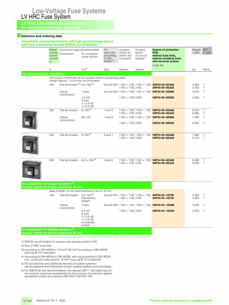
LV HRC fuse switch disconnectorsfor advanced technical demands
1/144
LV HRC Fuse SystemLow-Voltage Fuse Systems
Siemens ET B1 T · 2005
■ Selection and ordering data
Completely compartmentalized, with high speed closing feature with fuse monitoring through SIRIUS circuit-breaker 1)
1) SIRIUS circuit-breaker on request, also auxiliary switch 2 NC.
2) See LV HRC fuse links.
3) According to DIN 46234 or 16 mm2–95 mm2 according to DIN 46235 (use lug M 10 if required).
4) According to DIN 46234 or DIN 46235; with lug according to DIN 46235: min. conductor cross-section 16 mm2 (use lug M 12 if required).
5) For accessories and additional devices on busbar systems, see accessories and distribution board, busbar systems and switchgear.
6) For 3NP50 60 with flat terminations, the relevant 3NY1 106 cable lug cov-ers must be used (see accessories) for the purpose of protection against accidental contact according to DIN VDE 0106 Part 100.
Rateduninter-ruptedcurrent Iu
Connection type (double-ended) For fuse linksaccording to DIN 43620 2)
Auxiliary switch on switch dis-connector
Auxiliary switch on circuit-breaker
Degree of protection IP00, without fuse links, without isolating links, with terminal screws
Weight PS*/P. unitConnection for conductor
cross-section
1 item
Order No.
A mm2 Size Version Version kg Items
for mounting and installationwith plug-in connection of the auxiliary switch connecting cable (length approx. 1 m) to the circuit-breaker
160 Flat termination 6) 2.5–150 3) 00 and 000 1 NO + 1 NC 1 NO + 1 NC 3NP50 60–0EA86 2.480 11 NO + 1 NC 2 NO 3NP50 60–0EA26 2.550 1
Clamp connections
1-wire 00 and 000 1 NO + 1 NC 1 NO + 1 NC 3NP50 60–0EB86 2.610 1
2.5–50 2-wire 1× 2.5–50 1× 2.5–35
1 NO + 1 NC 2 NO 3NP50 60–0EB26 2.650 1
250 Flat termination 6–150 4) 1 and 0 1 NO + 1 NC 1 NO + 1 NC 3NP52 60–0EA86 6.010 11 NO + 1 NC 2 NO 3NP52 60–0EA26 6.860 1
Clamp connections
35–120 1 and 0 1 NO + 1 NC 1 NO + 1 NC 3NP52 60–0EB86 7.090 1
1 NO + 1 NC 2 NO 3NP52 60–0EB26 6.650 1
400 Flat termination 6–240 4) 2 and 1 1 NO + 1 NC 1 NO + 1 NC 3NP53 60–0EA86 7.080 11 NO + 1 NC 2 NO 3NP53 60–0EA26 5.410 1
630 Flat termination 6–2 × 240 4) 3 and 2 1 NO + 1 NC 1 NO + 1 NC 3NP54 60–0EA86 8.460 11 NO + 1 NC 2 NO 3NP54 60–0EA26 9.230 1
for adaptation to busbar systems 5), busbar center-to-center clearance 40 mm
Rails of width 12 mm and thickness 5 mm or 10 mm
160 Flat termination 2.5–150 3) 00 and 000 1 NO + 1 NC 1 NO + 1 NC 3NP50 65–1EF86 2.900 1Connection, bottom
1 NO + 1 NC 2 NO 3NP50 65–1EF26 2.950 1
Clamp connections
1-wire 00 and 000 1 NO + 1 NC 1 NO + 1 NC 3NP50 65–1EG86 3.020 1
2.5–50 2-wire 1× 2.5–50 1× 2.5–35 connection, bottom
1 NO + 1 NC 2 NO 3NP50 65–1EG26 2.970 1
for adaptation to busbar systems 5), busbar center-to-center clearance 60 mm
Use switch version "Mounting and installation" and busbar adapter, see accessories.
* You can order this quantity or a multiple thereof.

LV HRC fuse switch disconnectorsfor advanced technical demands
1/145
LV HRC Fuse SystemLow-Voltage Fuse Systems 1
345678910
1213
Siemens ET B1 T · 2005
■ Selection and ordering data
Completely compartmentalized, with high speed closing feature with electronic fuse monitoring ESÜ (self-powered) Version "A" (open-circuit principle) 1) for rated operational voltage Ue from 400 V to 500 V Incoming supply must come from above!
1) Version "R" (closed-circuit principle) on request! (See also block diagram)
2) See LV HRC fuse links.
3) According to DIN 46234 or 16 mm2–95 mm2 according to DIN 46235 (use lug M 10 if required).
4) According to DIN 46234 or DIN 46235; with lug according to DIN 46235: min. conductor cross-section 16 mm2 (use lug M 12 if required).
5) For 3NP50 60 with flat terminations, the relevant 3NY1 106 cable lug cov-ers must be used (see accessories) for the purpose of protection against accidental contact according to DIN VDE 0106 Part 100.
Rateduninter-ruptedcurrent Iu
Connection type (double-ended)
For fuse links according to DIN 43620 2)
Auxiliary switch on switch dis-connector
Auxiliary switch on fusemonitor
Degree of protection IP00, without fuse links, without isolating links, with terminal screws
Weight 1 item
PS*/P. unit
Connection for conduc-tor cross-sec-tion
Order No.
A mm2 Size Version Version kg Items
for mounting and installationwith plug-in connection of auxiliary switch connecting cable (length approx. 1 m) for fuse monitoring status display: green LED illuminated, fault indication: green LED flashing fuse failure: red LED (display per phase)
160 Flat termination 5)
2.5–120 3) 00 and 000 1 NO + 1 NC 2 NO + 1 NC 3NP50 60–0HA13 2.370 1
Clamp connections
1-wire2.5–50 2-wire 1× 2.5–50 1× 2.5–35
00 and 000 1 NO + 1 NC 2 NO + 1 NC 3NP50 60–0HB13 2.500 1
250 Flat termination
6–150 4) 1 and 0 1 NO + 1 NC 2 NO + 1 NC 3NP52 60–0HA13 5.860 1
400 Flat termination
6–240 4) 2 and 1 1 NO + 1 NC 2 NO + 1 NC 3NP53 60–0HA13 6.950 1
630 Flat termination
6–240 4) 3 and 2 1 NO + 1 NC 2 NO + 1 NC 3NP54 60–0HA13 8.510 1
* You can order this quantity or a multiple thereof.

LV HRC fuse switch disconnectorsfor advanced technical demands
1/146
LV HRC Fuse SystemLow-Voltage Fuse Systems
Siemens ET B1 T · 2005
■ Selection and ordering data
Completely compartmentalized, with high speed closing feature with electronic fuse monitoring (self-powered) Version "A" (open-circuit principle) 1) for rated operational voltage Ue from 400 V to 500 V Incoming supply must come from above!
1) Version "R" (closed-circuit principle) on request! (See also block diagram)
2) See LV HRC fuse links.
3) According to DIN 46234 or 16 mm2–95 mm2 according to DIN 46235 (use lug M 10 if required).
4) For accessories and additional devices on busbar systems, see accessories and components for distribution systems.
Rateduninter-ruptedcurrent Iu
Connection type (double-ended)
For fuse links accord-ing to DIN 43620 2)
Auxiliary switch on switch dis-connector
Auxiliary switch on fusemonitor
Degree of protection IP00, without fuse links, without isolating links, with terminal screws
Weight 1 item
PS*/P. unit
Connection for conductor cross-section
Order No.
A mm2 Size Version Version kg Items
for adaptation to busbar systems 4), busbar center-to-center clearance 40 mm
Rails of width 12 mm and thickness 5 mm or 10 mm
160 Flat termination
2.5–120 3) connection, bottom
00 and 000 1 NO + 1 NC 2 NO + 1 NC 3NP50 65–1HF13 2.770 1
for adaptation to busbar systems 4), busbar center-to-center clearance 60 mm
Use switch version "Mounting and installation" and busbar adapter, see accessories.
* You can order this quantity or a multiple thereof.

LV HRC fuse switch disconnectorsfor advanced technical demands
1/147
LV HRC Fuse SystemLow-Voltage Fuse Systems 1
345678910
1213
Siemens ET B1 T · 2005
■ Accessories
1) Also available in 2-wire version: 1 × 2.5 mm2 to 50 mm2 and 1 × 2.5 mm2 to 35 mm2.
2) Switch is wider than adapter; however, this can be expanded to 276 mm using 2 8US19 98–2BM00 lateral modules.
For fuse switch disconnectors
Height × Width Order No. Weight PS*/P. unit1 item
mm kg Items
for installation in any distribution board
3NY1 107
3NY1 106
Molded-plastic cover for installation in cabinet
3NP50 with and with-out auxiliary switch
215 × 135 3NY1 105 0.045 1
with auxiliary switch 215 × 135 3NY1 115 0.044 1
Molded-plastic cover for installation in metal front panel
with and without auxiliary switch
220 × 160 3NY1 125 0.062 1
Molded-plastic cover for connection terminals
3NP50 with and with-out auxiliary switch
265 × 135 3NY1 107 0.073 1
Molded-plastic cover for cable lug connections
3NP50 with and with-out auxiliary switch
290 × 135 3NY1 106 0.071 1
Molded-plastic cover for separate covering of top and bottomcable lug connections
with auxiliary switch 290 × 135 3NY1 116 0.071 1
3NP50 with and with-out auxiliary switch
290 × 135 3NY1 108 0.048 1
3NY1 212
Assembly kit for installationwith molded-plastic cover,fixing bracket and small components
3NP50 60 250 × 149 3NY1 208 0.531 1
3NP52 60 300 × 220 3NY1 210 0.287 1
3NP53 60 300 × 245 3NY1 211 0.298 1
3NP54 60 300 × 290 3NY1 212 0.313 1
for switches with and without auxiliary switch
3TX6 546–3B
Cover for cable lug connection(1 set = 6 items) screw ontofree screw endfor protection againstaccidental contact
3NP52 cover length 99 mm 3NY1 241 0.205 1 set
3NP53/3NP54 60 cover length 95 mm 3TX6 546–3B 0.260 1 setcover length 120 mm 3NY1 245 0.336 1 set
for installation in any distribution board
3NY1 907
Conductor cross-section
Clamp connections (1 set = 3 items)
3NP50 2.5–50 mm2 1) 3NY1 903 0.108 1 set
3NP52 35–120 mm2 3NY1 907 0.225 1 set
8US12 10–4AG00
Busbar adapter for 60-mm busbar system
3NP50 108 mm wide 8US12 91–4SB00 0.551 1
3NP52, 3NP53.3NP54 2)
250 mm wide (length 320 mm, terminal screws M 10, connecting cables must be made up)
8US12 10–4AG00 3.060 1
Sealing eyecan be retrofitted(1 pack = 10 items)
3NP50 3NY1 940 0.010 1 set
* You can order this quantity or a multiple thereof.

LV HRC fuse switch disconnectorsfor advanced technical demands
1/148
LV HRC Fuse SystemLow-Voltage Fuse Systems
Siemens ET B1 T · 2005
■ Accessories
1) If retrofitted, drill holes required.
For fuse switch disconnectors
Order No. Weight PS*/P. unit1 item
kg Items
3NY1 074
Handle unit 3NP50 6 .–.C. .0 3NY1 074 0.620 13NP52 60–.C. .0 3NY1 371 0.263 13NP53 60–.C. .0 3NY1 372 1.510 13NP54 60–.C. .0 3NY1 373 1.690 1
with fuse monitoring through circuit-breaker 3RV1 (with auxiliary switch 1 NO + 1 NC), with plug-in connection, without connector and connecting cable
3NP50 6 .–.E. .6 3NY1 420 1.400 13NP52 60–.E. .6 3NY1 421 1.900 13NP53 60–.E. .6 3NY1 422 1.980 13NP54 60–.E. .6 3NY1 423 2.600 1
Connector and connecting cable1 m long 3NP5 with 3RV1 3NY1 910 0.097 13 m long 3NY1 911 0.261 1
3NY1 513–3
with electronic 3NP50 6 .–.H .13 3NY1 513–0 1.230 1fuse monitoring for 400 V-500 V 3NP52 60–.H .13 3NY1 513–2 2.130 1(with auxiliary switch 2 NO + 1 NC), 3NP53 60–.H .13 3NY1 513–3 2.140 1with plug-in connection, without connector and connecting cable
3NP54 60–.H .13 3NY1 513–4 0.325 1
3NY1 915
Connector and connecting cable (6-pole)3 m long
3NP5 with ESÜ 3NY1 915 0.372 1
Strain relief assembly kit for control cable of
3NP5 with ESÜ 3NY1 918 0.024 1 set
Auxiliary switch 1 NO + 1 NC
3NY3 033
with actuating cams, screws and washers (mounting kit)
3NP50 1) 3NY3 033 0.015 1
3NY3 034
with fixing bracket and screws (mounting kit)
3NP52–3NP54 3NY3 034 0.015 1
3NY4 031
Arc chamber (for 3NP52, 3NP53 and 3NP54, 3 itemseach are required)
3NP50 3NY4 031 0.218 1
3NY4 011
3NP52 3NY4 011 0.215 1
3NP53, 3NP54 3NY4 012 0.240 1
Molded-plastic covers 300 × 220 mm 3NY1 210 3NY1 102 0.071 1as replacement for covers 300 × 245 mm 3NY1 211 3NY1 103 0.075 1from assembly kits for installation (without fixing brackets and small components)
300 × 290 mm 3NY1 212 3NY1 104 0.084 1
* You can order this quantity or a multiple thereof.

LV HRC fuse switch disconnectors
1/149
LV HRC Fuse SystemLow-Voltage Fuse Systems 1
345678910
1213
Siemens ET B1 T · 2005
■ Dimensional drawings
3NP40 10 Cutout for 3NP35 and 3NP40 10
3NP40 10 with 3NY1 995 quick retaining plate mounting rail center-to-center clearance 125 mm
3NY1 995 quick fitting platefor 3NP40 10 and 3NP40 70
3NP40 10 with 3NY1 237 3-phase busbar for 2 fuse switch disconnectors
3NY1 265cap for 3NY1 2383-phase busbar
3NP40 10 with 3NY1 235 triple terminal
3NP40 10 with 3NY1 236 supply terminal
3NP40 10 with 3NY1 251 molded-plastic cover
3NP40 15–1CJ01 with busbar adapter, flat, rails; width 12 mm or 15 mm and thickness 5 mm or 10 mm, bottom connection
3NP40 15–1CK01 with busbar adapter, flat, rails; width 12 mm or 15 mm and thickness 5 mm or 10 mm, top connection
3NP40 15–0CJ01 with busbar adapter, deep, rails; width 12 mm or 15 mmand thickness 5 mm or 10 mm, bottom connection
3NP40 16–1CJ01 with busbar adapter, rails of width 12, 15, 20 mm or 30 mm and thickness 5 mm or 10 mm, flat, T, I profiles and other renowned busbar systems, bottom connection
3NP40 16–1CK01 with busbar adapter, rails of width 12, 15, 20, 25 mm or 30 mm and thickness 5 mm or 10 mm, flat, T, I profiles and other renowned busbar systems, top connection
� � � �� �
�����
���� ����
� � � � � � � �
� � � � �
� �� �
��
� � �
�
���
�����
� � �
� �
�����
� � � � � � � � � � � � � � � �
���
��
���
��
���
�
�����
��
��
�
�
�����
���
��
��
��
���
��
������
�
�
�
��
��
�
����
��
��
�
��
��
��� ��
����
��
��
��
��
For installation STAB 8GD wall-mounted distribution boards, upper perforationswith 50 mm clearance
�
��
��
��
�
�� ��
��
�� �
���� ���
��
��
������
�
��
��
��
�
���
��
��
��
�
��
��
�
�
��
��
���� �� ���
��
��
��
��
���� �����
��
��
���
��������
��
����
�
��
����
� ��
�� ������
���
��
��
���� �������
��
��
��
��
��
��
���
��
��
�
�� �����
�
��
���
��
���� ���� �
��
��
��
��
��
��
���
�� �
�
���
��
�
��
��
�
�
���� ����
��
��
��
��
���
��
��
�� �����
��
�����
��
�
��
���
��
���� ����
��
����
��
��
���
��
��
������ �����
��� �
��
�
��
���
��
���� ����
��
��
��
��
�
��
��
���
����
�� �����
���

LV HRC fuse switch disconnectors
1/150
LV HRC Fuse SystemLow-Voltage Fuse Systems
Siemens ET B1 T · 2005
■ Dimensional drawings
1) h = distance from upper edge of panel cutout to center of disconnector mounting.
2) Cover is placed open on the switchgear cabinet panel, for cover behind control cabinet panel: cutout dimensions on request.
3NP40 70 for mounting
3NP42 70, 3NP43 70, 3NP44 70 for mounting
Drilling pattern for 3NP40 70
3NP40 75–0 with busbar adapter, deep, rails of width 12 mm or 15 mm and thickness 5 mm or 10 mm
3NP40 75–1 with busbar adapter, flat, rails of width 12 mm or 15 mm and thickness 5 mm or 10 mm
For metal frames cutout for 3NP4
�����������
�
��
�
��
� � � �
� �
�
� �
�
� �
��
������
��
�
116
114
85
130
50
NS
E0_
0021
0a
2 6,5
�11
NSE0_00522a
122,5
M 685 81
,797
,5
65
50
65
11NSE0_00211a
2
81
50
81
NSE0_00212a2
� 11
NS
E0_
0052
3a
118
5070 11
019
5
5,8N
SE
0_00
524a
198
114
116
157
274,
4
130
25
5011
NS
E0_
0052
5a
224
174
315
130
50
11
NS
E0_
0052
6a
270
177,
526
7
162
50
11
Type a b c d e
3NP42 70 184 243 66 45.5 2153NP43 70 210 288 80 48 2553NP44 70 256 300 94.5 48 267
For plastic frameCutouts 2)
for 3NP40 70Cutouts 2)
for 3NP42
Cutouts 2)
for 3NP43Cutouts 2)
for 3NP44
3NY73 22 quick retaining plate
Drilling pattern for 3NP42 70
Drilling pattern for 3NP43 70 Drilling pattern for 3NP44
$ Bottom edge disconnector-base % Center disconnector-base
��
��
��
��
�
��
��
�
�� ��
�
��
��
��
��
�� ���
��
���
��
��
��
�
���
��
��
��
�
��
�
��
���
��
��
��
��
��
�� ���
��
���
��
��
��
�
���
��
��
��
�
�
��
���
Type Cover between assembly kit
Panel cutout min.
Type B H B H h 1)
Insulating cover behind panel
3NP40 1 3NY1 251 130 215 100 180 1003NP40 7 3NY7 200,
3NY7 201130 215 118 195 110
3NP42 7 3NY7 220 220 375 210 275 1573NP43 7 3NY7 230 245 375 235 315 1743NP44 7 3NY7 240 290 375 280 325 178
Insulating cover in front of panel
3NP40 1 3NY1 251 130 215 100 155 873NP40 7 3NY7 200,
3NY7 201130 215 118 195 110
3NP42 7 3NY7 220 220 375 198 275 1573NP43 7 3NY7 230 245 375 224 315 1743NP44 7 3NY7 240 290 375 270 325 178
��
���
���
��
�
��

LV HRC fuse switch disconnectors
1/151
LV HRC Fuse SystemLow-Voltage Fuse Systems 1
345678910
1213
Siemens ET B1 T · 2005
■ Dimensional drawings
3NP40 70–0F for mounting and installation
3NP40 75–0F with busbar adapter, deep, 40 mm, rails; width 12 mm or 15 mm and thickness 5 mm or 10 mm
3NP40 75–1F with busbar adapter, flat, 40 mm, rails; width 12 mm or 15 mm and thickness 5 mm or 10 mm
3NP40 76–0F with busbar adapter, flat, 60 mm, rails; width 12 mm or 30 mm and thickness 5 mm or 10 mm
�����������
� � �
� � � � � � �
����
��
��
� �
��
���
���
��
���
���
���
�
�
�
���
�
�
�����
���
��
���
���
��
��� �
�
��
����� ��
���
���
�

LV HRC fuse switch disconnectors
1/152
LV HRC Fuse SystemLow-Voltage Fuse Systems
Siemens ET B1 T · 2005
■ Dimensional drawings
1) For VBG4 plus dimension c of cable lug covers (see page 1/153).
2) When installed together with size 000 or size 00 in STAB/SIKUS distribution boards, 3NY7 820 molded-plastic cover is used as a depth compensation (underneath).
3NP40 76–1 with busbar adapter, rails; width 12 mm to 30 mm and thickness 5 mm or 10 mm, flat-, T and I profiles
3NP42 75–1 3NP42 76–1 3NP43 76–1 3NP44 76–1
with busbar adapter, rails; width 12 mm to 30 mm and thickness 5 mm or 10 mm flat, T and I profiles
��
��
��
���
�
�
�
��
�
�
�
�
��
��
�
��
��
��
�
�
�
��
��
��
�
��
��
Type a b 1) c d e f
3NP42 75-1 184 243 83 2) 45.5 111 403NP42 76-1 184 243 83 2) 45.5 111 603NP43 76-1 210 288 97 48 125 603NP44 76-1 256 300 112 48 139 60
3NY7 200 molded-plastic cover for 3NP40 7 for installation in any distribution boards
3NY7 201 molded-plastic cover for 3NP40 7.- for 3NP40 7.-CA01
3NY7 220 molded-plastic cover for 3NP42 for installation in any distribution boards
3NY7 230 molded-plastic cover for 3NP43 for installation in any distribution boards
3NY7 240 molded-plastic cover for 3NP44 for installation in any distribution boards
3NY7 820 molded-plastic cover for 1 3NP42 70 switch-disconnector for installation in STAB-/SIKUS distribution boards
������ ��
��
�
NS
E0_
0052
7a
130
215
40
�������
���
��
���
�������
���
����
���������
���
���
���
��������
�
�
���
��

LV HRC fuse switch disconnectors
1/153
LV HRC Fuse SystemLow-Voltage Fuse Systems 1
345678910
1213
Siemens ET B1 T · 2005
■ Dimensional drawings
3NY7 500 molded-plastic cover for 1 3NP40 switch-disconnector, left for installation in SIKUS 3200-, STAB 160- and 400- and SIKUS 630 distribution boards
3NY7 501 molded-plastic cover for 1 3NP40 switch-disconnector, right for installation in SIKUS 3200-, STAB 160- and 400- and SIKUS 630 distribution boards
3NY7 502 molded-plastic cover for 2x 3NP40 switch disconnectors for installation in SIKUS 3200-, STAB 160- and 400- and SIKUS 630 distribution boards
Cable lug cover for 3NP40 7 with flat termination, 3NY7 101
Cable lug cover for 3NP42 to 3NP44, 3NY7 121, 3NY7 131, 3NY7 141
��
��
��
�
���
���
�
��
��
���
��
���
���
�
�
�����������
� � �
� �
���
��
�����
������
�� �
�
��
������
Type a b c
3NY7 121 181 65 673NY7 131 207 79 503NY7 141 253 94 47

LV HRC fuse switch disconnectors
1/154
LV HRC Fuse SystemLow-Voltage Fuse Systems
Siemens ET B1 T · 2005
■ Dimensional drawings
1) h = distance from upper edge of panel cutout to center of disconnector mounting.
2) With standard molded-plastic cover behind panel and corresponding panel cutout, the standard switching capacity is reduced to the following AC 23B values: For 400 V Ie 160 V, at 500 V from Ie 160 V to 125 A and at 690 V from Ie 100 A to 50 A.
3NP50 60, 160 A for mounting
3NP50 60, 160 A with molded-plastic cover for any type of installation
3NY1 107 molded-plastic cover
3NP50 60, 160 A with fuse monitoring through 3RV1 circuit-breaker, with plug-in connector
For plastic frame Cutout for 3NP50 60, with and without auxiliary switch
Cutout for 3NY1 208 mounting kit
For metal frames Cutout for 3NP5
116 1517
397
19663
6384
70
36 36134
22M8 3416
531
97,5
19
NS
E00
226
Ø5,8
228Auxiliary switch Type a b c d
3NY1 105 135 215 95.5 38
3NY1 115 135 215 95.5 38
3NY1 106 135 290 144.5 64
3NY1 108 135 290 144.5 64
3NY1 208 149 250 115 53.5
cb
d12
NSE0_00231a
a 45 2
230
36
NSE0_00227a
135
30°30
30°30
��
�
��
�
�����
���
�
�
��
��
���
9120
5
NSE0_00229a
130
5,8
70
NS
E00
230
126,5
191
207,
5
6143
Type Cover between assembly kit
Panel cutout min.
Type B H B H h 1)
Molded-plastic cover behind panel
3NP50 6 3NY1 105 2) 135 215 130 206 115
3NP50 6 3NY1 125
3NP52 6 3NY1 210 222 300 210 293 146
3NP53 6 3NY1 211 245 300 235 293 146
3NP54 6 3NY1 212 290 300 280 293 146
Molded-plastic cover in front of panel
3NP50 6 3NY1 105 135 215 130 205 115
3NP50 6 3NY1 208 149 250 143 191 –
3NP52 6 3NY1 210 220 300 210 262 132
3NP53 6 3NY1 211 245 300 234 262 132
3NP54 6 3NY1 212 290 300 279 262 132
�
��
��
��
�
��

LV HRC fuse switch disconnectors
1/155
LV HRC Fuse SystemLow-Voltage Fuse Systems 1
345678910
1213
Siemens ET B1 T · 2005
■ Dimensional drawings3NP5. 60, 250 to 630 A for mounting
3NP5. 60, 250 to 630 A with molded-plastic cover, for installation
3NP5. 60, 250 to 630 A with fuse monitoring through 3RV circuit-breaker, with plug-in connection
3NP50 65, 160 A with busbar adapter, with fuse monitoring through 3RV circuit-breaker, with plug-in connection
3NP50 65, 160 A with busbar adapter, rails; width 12 mm and thickness 5 mm or 10 mm
3NP5. 60, 160 to 630 A with electronic fuse monitoring, with plug-in connection and control cable
3NP50 60, 160 A with electronic fuse monitoring, with plug-in connection and control cable
3NP5. 60, 250 to 630 A with electronic fuse monitoring, with plug-in connection and control cable
��
��
��
�
�
��
��
��
��
��
� ��
��
� ���
� ��
�
�����
�
�� �
�
Cutout for 3NP52 60, 3NP53 60 and 3NP54 60
1) Through-hole for screw
Type a b c d e f g h
3NP52 60 207 202 130 93 62 176 38 413NP53 60 231 226 130 106 70 192 39 393NP54 60 276 271 200 111 85 207 40.5 40.5
Type I k 1) l 1) m n o q r
3NP52 60 11.5 M 10 M 8 336 25 32 212 3.63NP53 60 11.5 M 10 M 10 352 25 25 228 4.43NP54 60 11.5 M 10 M 10 367 30 25 243 6
Type s t u w x y
3NP52 60 156 210 89.5 220 186.5 200.53NP53 60 180 234 105.5 245 202.5 216.53NP54 60 225 279 120.5 290 217.5 231.5
� � � � � � � � � � �
���
�
� �
�
� �
���
�
�
��
������
�
���
�
�
� �
���������
�
�
������
���
�������
������ ���
�
���
�� ��
��
���
�������
���
����
���
���� ��
�
���
��
� ��
�������
� ��
��
���
������
������
�������
� �
���������
���
��

LV HRC fuse switch disconnectors
1/156
LV HRC Fuse SystemLow-Voltage Fuse Systems
Siemens ET B1 T · 2005
■ Schematics
SENTRIC 3NP fuse switch disconnectors with fuse monitoring (with circuit-breaker 3RV1, with auxiliary switch 1 NO + 1 NC)
SENTRIC 3NP5 fuse switch disconnector with electronic fuse monitoring
Function auxiliary contact - main contact at SENTRIC 3NP4 and 3NP5
42
10 5 10 15 20 61°
13
14 22
0 5 10 15 20 77°
NS
E 0
0174
d
0 5 10 15 20 70°
(3 S)1-2 (1 Ö)1-4 (1 S)
3NP40 1,3NP4. 7
21
Contact closed
Contact open
for 3NP401 and 3NP4.7
Auxiliary circuit switch
ON OFF
for 3NP5
13-1421-223NP52 60
3NP54 60
13-1421-223NP50 60
3NP53 60
(1 NO)(1 NC)(3 NO)
(1 NO)(1 NC)(3 NO)(3 NO)(3 NO)
ON OFF
Circuit diagram of main circuit Circuit diagram of auxiliary circuit
Q1 = fuse switch disconnector Q2 = circuit-breaker K1 = contactor S1 = ON pushbutton S0 = OFF pushbutton F1 = overload relay F2 = control-circuit fuse
������
��
��
��
��
�� ��
��
��
��
��
� � � � � �
� � �
� � �
��
��
�
����
��
���
����� ��
������������
�� ������������
��
��
��
�� ��
��
����� ��
��
��
��
Block diagram
1
11 12 23 24 33 34
6 5 4 3 2
BN BU GY WH RDBK
X1
L1 L2 L3
F1 F2 F3
L1' L2' L3'
NSE00177A
Micro-controller Switching stage
Power supplyunit
Voltages
Synchroni-zation signals
Fault F3
Fault F2
Fault F1
Resistornetwork
Parameterization
Signal lines
LED display
Running
Version "A" (open-circuit principle): Auxiliary switches only pick up if fuse faulty and voltage is applied. Version "R" (closed-circuit principle): Auxiliary contacts pick up as soon as voltage is applied and as long as fuses are intact.
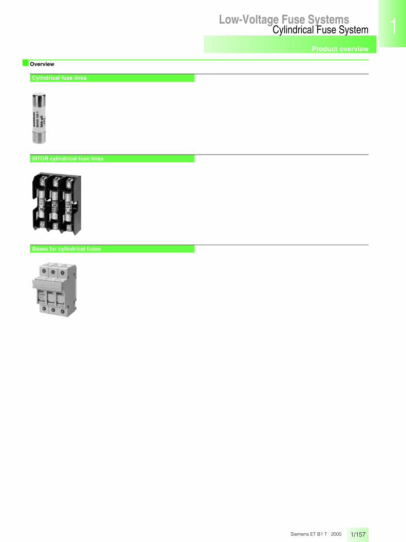
Product overview
1/157
Cylindrical Fuse SystemLow-Voltage Fuse Systems 1
345678910
1213
Siemens ET B1 T · 2005
Low-Voltage Fuse Systems
■ Overview
Cylindrical fuse links
SITOR cylindrical fuse links
Bases for cylindrical fuses

Product overview
1/158
Cylindrical Fuse SystemLow-Voltage Fuse Systems
Siemens ET B1 T · 2005
■ Benefits
ApplicationCylindrical fuses are used for line protection or for protecting switch-ing devices. The design is used all over the world.
DisconnectorsCylinder fuse bases are disconnectors that cannot be switched under load.
VDE markCylindrical fuses are not included in the standard DIN VDE 0636-201, the German version of IEC 60269-2-1. Therefore this design did not receive the VDE mark.
SafetyNo-voltage changing of the fuse links.
Signal detectorWhen a fuse link fails, an LED in the window of the fuse link flashes.

Cylindrical fuse links
1/159
Cylindrical Fuse SystemLow-Voltage Fuse Systems 1
345678910
1213
Siemens ET B1 T · 2005* You can order this quantity or a multiple thereof.
■ Technical specifications
■ Selection and ordering data
Cylindrical fuse linksType 3NW6 3.. 3NW6 0.. 3NW6 1.. 3NW6 2..
Size mm × mm 8 × 32 10 × 38 14 × 51 22 × 58
Standards IEC 60269-1, -2, -2-1NF C 60-200, 63-210, 63-211NBN C 63269-2en-2-1CEI 32-4, -12
Utilization category gL/gG gL/gG and aM
Rated voltages Un V AC 400 or 500 (see selection table)
Rated current In A 0.5 ... 100
Rated breaking capacity kA AC 100, but 400 V versions: 20
Mounting position any, but preferably vertical
Size In Un Utilization category gL/gG Utilization category aM Weight PS*/P. unitOrder No. Order No. 1 item
mm × mm A V AC kg Items
Cylindrical fuse links8 × 32 2 400 3NW6 302-1 – 0.004 10
4 3NW6 304-1 – 0.004 106 3NW6 301-1 – 0.004 10
10 3NW6 303-1 – 0.004 1016 3NW6 305-1 – 0.004 1020 3NW6 307-1 – 0.004 10
10 × 38 0.5 500 – 3NW8 000-1 0.003 101 – 3NW8 011-1 0.008 10
2 3NW6 002-1 3NW8 002-1 0.008 104 3NW6 004-1 3NW8 004-1 0.008 106 3NW6 001-1 3NW8 001-1 0.008 10
8 3NW6 008-1 3NW8 008-1 0.008 1010 3NW6 003-1 3NW8 003-1 0.008 1012 3NW6 006-1 3NW8 006-1 0.008 10
16 3NW6 005-1 3NW8 005-1 0.008 1020 3NW6 007-1 3NW8 007-1 0.008 1025 3NW6 010-1 – 0.008 10
400 – 3NW8 010-1 0.008 10
32 3NW6 012-1 – 0.008 10
14 × 51 2 500 – 3NW8 102-1 0.019 104 3NW6 104-1 3NW8 104-1 0.019 106 3NW6 101-1 3NW8 101-1 0.019 10
8 3NW6 108-1 3NW8 108-1 0.019 1010 3NW6 103-1 3NW8 103-1 0.019 1012 3NW6 106-1 3NW8 106-1 0.019 10
16 3NW6 105-1 3NW8 105-1 0.019 1020 3NW6 107-1 3NW8 107-1 0.019 1025 3NW6 110-1 3NW8 110-1 0.019 10
32 3NW6 112-1 3NW8 112-1 0.019 1040 3NW6 117-1 3NW8 117-1 0.019 10
50 400 3NW6 120-1 3NW8 120-1 0.019 10
22 × 58 8 500 3NW6 208-1 – 0.051 1010 3NW6 203-1 3NW8 203-1 0.051 1012 3NW6 206-1 3NW8 206-1 0.051 10
16 3NW6 205-1 3NW8 205-1 0.051 1020 3NW6 207-1 3NW8 207-1 0.051 1025 3NW6 210-1 3NW8 210-1 0.051 10
32 3NW6 212-1 3NW8 212-1 0.051 1040 3NW6 217-1 3NW8 217-1 0.051 1050 3NW6 220-1 3NW8 220-1 0.051 10
63 3NW6 222-1 3NW8 222-1 0.051 1080 3NW6 224-1 3NW8 224-1 0.051 10
100 400 3NW6 230-1 3NW8 230-1 0.051 10

Cylindrical fuse links
1/160
Cylindrical Fuse SystemLow-Voltage Fuse Systems
Siemens ET B1 T · 2005
■ Characteristic curves
Series 3NW6 30.-1Size: 8 mm × 32 mmUtilization category: gL/gGRated voltage: 400 V ACRated current: 2 ... 20 ATime/current characteristics diagram
Current limitation diagram
$ Peak short-circuit current with largest DC component
% Peak short-circuit current without DC component
Melting I2ts values diagram
�� � �
� � � �
�
�
�
� � � �
�� � � �� � �� � � �� � �
�
�
�
� � �
�
�
�
� � �
�
�
�
� � �
�
�
�
� � �
�
�
�
� � �
�������
� � � ��
�
� � � � � �
���
� � � � � � � � � �
� � � � � � � � � �
� � � � �� � ��
� �
�
�
�
�
�
�
�
� � � � � �
���
� � �
�
� � �� � �� � � �� � �� � � �
�������
�
� � �
�
� �
� � �
� �
� � � �
� � � �
� � � �
� � �
Type In Pv �� I2ts I2ta1 ms 400 V AC
A W K A2s A2s
3NW6 302-1 2 2 27 1.6 63NW6 304-1 4 1.5 19 5 213NW6 301-1 6 1.5 20.5 48 85
3NW6 303-1 10 0.7 15 230 5303NW6 305-1 16 1.1 29 600 14003NW6 307-1 20 1.7 34.5 790 1800
�� �
�
�
�
� �
�
�
�
� �
�
�
�
� �
�
�
�
� �
�������
�
�
�
�
�
� � � �
������
�
� � � � � � � �
�� � � � �� � � � �
��
��
�

Cylindrical fuse links
1/161
Cylindrical Fuse SystemLow-Voltage Fuse Systems 1
345678910
1213
Siemens ET B1 T · 2005
■ Characteristic curves
Series 3NW6 0Size: 10 mm × 38 mmUtilization category: gL/gGRated voltage: 500 V AC (2 ... 25 A)
400 V AC (32 A)Rated current: 2 ... 32 ATime/current characteristics diagram
Current limitation diagram
$ Peak short-circuit current with largest DC component
% Peak short-circuit current without DC component
Melting I2ts values diagram
�� � �
� � � �
�
�
�
� � � �
�� � � �� � �� � � �� � �
�
�
�
� � �
�
�
�
� � �
�
�
�
� � �
�
�
�
� � �
�
�
�
� � �
�������
� � � ��
�
� � � � � �
���
���
��
���
��
����
����
����
����
����
����
� � � � �� � ��
� �
�
�
�
�
�
�
�
� � � � � �
���
� � �
�
� � �� � �� � � �� � �� � � �
�������
�
� � �
�
� � �
� �
� �
� � � �
� � � �
� � �
� �
� � � �
� � � �
� � � �
� � � �
Type In Pv �� I2ts I2ta1 ms 230 V AC 400 V AC 500 V AC
A W K A2s A2s A2s A2s
3NW6 002-1 2 2.2 32 1.6 5 6.5 83NW6 004-1 4 1.2 16.5 5 16 19 263NW6 001-1 6 1.6 23 48 70 84 120
3NW6 008-1 8 2.3 35 110 180 140 3503NW6 003-1 10 0.7 16 230 420 570 10503NW6 006-1 12 0.9 33 390 510 600 1200
3NW6 005-1 16 1.3 38 600 950 1300 17003NW6 007-1 20 2.1 51.5 640 1200 1700 21003NW6 010-1 25 2.1 54 1300 2200 2800 3200
3NW6 012-1 32 2.5 51 2360 4000 4200 –
�� �
�
�
�
� �
�
�
�
� �
�
�
�
� �
�
�
�
� �
�������
�
�
�
�
�
� � � �
������
�
� � � � � �
�
� � � � �� � � � �� � � � �
��
��
�
� � � � � � � � �

Cylindrical fuse links
1/162
Cylindrical Fuse SystemLow-Voltage Fuse Systems
Siemens ET B1 T · 2005
■ Characteristic curves
Series 3NW6 1Size: 14 mm × 51 mmUtilization category: gL/gGRated voltage: 500 V AC (4 ... 40 A)
400 V AC (50 A)Rated current: 4 ... 50 ATime/current characteristics diagram
Current limitation diagram
$ Peak short-circuit current with largest DC component
% Peak short-circuit current without DC component
Melting I2ts values diagram
�� � �
� � � �
�
�
�
� � � �
�� � � �� � �� � � �� � �
�
�
�
� � �
�
�
�
� � �
�
�
�
� � �
�
�
�
� � �
�
�
�
� � �
�������
� � � ��
�
� � � � � �
���
��
���
����
����
����
����
����
���
����
��
����
� � �
�
� � � � � �
���
� �
�������
�
� � � � � � �� � � � � � �� � � � � � �� � �
�
�
�
� � �
� �
�
�
�
� � �
� �
� � �
� �
� � � �
� � � �
� � � �
� � � �
� � � �
� � � �
� � �
� � � �
Type In Pv �� I2ts I2ta1 ms 230 V AC 400 V AC 500 V AC
A W K A2s A2s A2s A2s
3NW6 104-1 4 1.9 19 5 16 20 263NW6 101-1 6 2.5 25 48 85 100 1203NW6 108-1 8 2.4 18 110 200 250 350
3NW6 103-1 10 0.8 12 230 420 750 10503NW6 106-1 12 1.0 16 390 600 800 12003NW6 105-1 16 1.6 27 600 1000 1400 1700
3NW6 107-1 20 2.3 32.5 670 1400 1800 21003NW6 116-1 25 2.2 31.5 1300 2300 2800 32003NW6 112-1 32 3.2 39.5 2500 4100 5500 6500
3NW6 117-1 40 4.5 48 3600 6100 8000 92003NW6 120-1 50 4.8 55 8000 12200 16000 –
� �
�
�
�
� �
�
�
�
� �
�
�
�
� �
�
�
�
� �
�������
�
�
�
�
�
� � � �
������
�
�
� � � � �� � � � �� � � � �
��
��
�
�
�
�
� � �
� � � � � �� � � �� � � � � �� � �

Cylindrical fuse links
1/163
Cylindrical Fuse SystemLow-Voltage Fuse Systems 1
345678910
1213
Siemens ET B1 T · 2005
■ Characteristic curves
Series 3NW6 2Size: 22 mm × 58 mmUtilization category: gL/gGRated voltage: 500 V AC (8 ... 80 A)
400 V AC (100 A)Rated current: 8 ... 100 ATime/current characteristics diagram
Current limitation diagram
$ Peak short-circuit current with largest DC component
% Peak short-circuit current without DC component
Melting I2ts values diagram
�� � �
� � � �
�
�
�
� � � �
�� � � �� � �� � � �� � �
�
�
�
� � �
�
�
�
� � �
�
�
�
� � �
�
�
�
� � �
�
�
�
� � �
�������
� � � ��
�
� � � � � �
��� ����
����
����
����
���
����
����
���
�����
����
����
��
� � � � �� � ��
� �
�
�
�
�
� � � � � �
���
� �
�
� � �� � �� � � �� � �� � � �
�������
�
� �
�
� � � �
� � � �
� � � �
� � � �
�
�
�
�
�
� � �
� � � �
� � � �
� � �
� � � � �
� �
� � � �
� � � �
� �
Type In Pv �� I2ts I2ta1 ms 230 V AC 400 V AC 500 V AC
A W K A2s A2s A2s A2s
3NW6 208-1 8 2.5 15 110 200 170 3503NW6 203-1 10 0.9 10.5 230 420 760 10503NW6 206-1 12 1.1 12 390 600 800 1200
3NW6 205-1 16 1.6 14.5 600 1000 1400 17003NW6 207-1 20 2.4 22.5 670 1200 1800 22003NW6 210-1 25 2.7 24 1300 2100 2800 3300
3NW6 212-1 32 3.2 28 2450 4400 6100 72003NW6 217-1 40 4.9 35 3600 6200 8000 100003NW6 220-1 50 5.9 46 6800 11400 16200 20600
3NW6 222-1 63 6.8 48 12500 18800 24000 300003NW6 224-1 80 7.5 48 24700 30500 43000 525003NW6 230-1 100 8.4 55 46000 64700 80000 –
� �
�
�
�
� �
�
�
�
� �
�
�
�
� �
�
�
�
� �
�������
�
�
�
�
�
� � � �
������
�
�
� � � � �� � � � �� � � � �
��
��
�
�
�
�
� � �
� � � �� � � � �� � � � � �� � � �� �� ��

Cylindrical fuse links
1/164
Cylindrical Fuse SystemLow-Voltage Fuse Systems
Siemens ET B1 T · 2005
■ Characteristic curves
Series 3NW8Size: 10 mm × 38 mm
14 mm × 51 mm22 mm × 58 mm
Utilization category: aMRated voltage: 500 V AC
400 V AC (3NW8 120-1, 3NW8 230-1)Rated current: 0.5 ... 100 ATime/current characteristics diagram
Current limitation diagram
$ Peak short-circuit current with largest DC component
% Peak short-circuit current without DC component
Melting I2ts values diagram
�
� � � �
�
�
�
� � � �
�� � � �� �� � � �� � �
�
�
�
� � � �
�
�
�
� � �
�
�
�
� � �
�
�
�
� � �
�
�
�
� � �
�������
� � � ��
�
� � � � � �
���
����
����
����
����
���
����
����
���
�����
� � �
�����
���
���
��
����
����
��
���
� � ��
�
� � � � � �
���
� �
�������
�
� � � � � � �� � � � � � �� � � � � � �� � � �
�
�
�
� � �
�
�
�
� � �
�
� �
� � � � �
� � � � �
� � �
� � � �
� � � �
� � �
� � � �
� � � �
� � � �
� � � �
� � � �
� � � �
� �
� � �
� �
� � �
� � �
� �
�
�
�
� �
�
�
�
� �
�
�
�
� �
�
�
�
� �
�
�
�
�
�
� � � �
������
�
� � � �
�
�
�
� � �
�
�������
�
�
�
� ��
�� � � � �� � � � �
��
��
�
� � � � � � � � � � � � � � � � � � � � � � �� � �

Cylindrical fuse inks
1/165
Cylindrical Fuse SystemLow-Voltage Fuse Systems 1
345678910
1213
Siemens ET B1 T · 2005
■ Characteristic curves
Series 3NW8Size: 10 mm × 38 mm
14 mm × 51 mm22 mm × 58 mm
Utilization category: aMRated voltage: 500 V AC
400 V AC (3NW8 120-1, 3NW8 230-1)Rated current: 0.5 ... 100 A
■ Dimensional drawings
Type Size In Pv �� I2ts I2ta1 ms 400 V AC 500 V AC
mm A W K A2s A2s A2s
3NW8 000-1 10 × 38 0.5 0.5 2.2 3 5 83NW8 011-1 1 0.08 1.5 7 15 203NW8 002-1 2 0.15 2.3 30 70 82
3NW8 004-1 4 0.25 4.5 100 220 2503NW8 001-1 6 0.4 7 140 300 3403NW8 008-1 8 0.5 8 240 510 610
3NW8 003-1 10 0.56 10 440 960 11003NW8 006-1 12 0.66 12.5 600 1300 15003NW8 005-1 16 0.8 15 800 2200 2500
3NW8 007-1 20 1 20 1350 3200 32003NW8 010-1 25 1.25 23 2300 5000 –
3NW8 102-1 14 × 51 2 0.2 2.5 30 70 823NW8 104-1 4 0.35 4 100 220 2503NW8 101-1 6 0.5 6 140 300 340
3NW8 108-1 8 0.6 7.5 240 510 6103NW8 103-1 10 0.65 8 440 960 11003NW8 106-1 12 0.75 10 600 1300 1500
3NW8 105-1 16 1.08 14 800 2200 25003NW8 107-1 20 1.3 18.5 1350 3200 38003NW8 110-1 25 1.7 20 2300 5000 5700
3NW8 112-1 32 1.9 23 3600 8000 95003NW8 117-1 40 2.25 24 5800 13000 145003NW8 120-1 50 2.8 34 10000 23000 –
3NW8 203-1 22 × 58 10 0.75 7.5 440 960 11003NW8 206-1 12 0.8 8.5 600 1300 15003NW8 205-1 16 1.2 13 800 2200 2500
3NW8 207-1 20 1.46 16.6 1350 3200 38003NW8 210-1 25 1.7 17.8 2300 5000 57003NW8 212-1 32 2.5 27 3600 8000 9500
3NW8 217-1 40 3 23 5800 13000 145003NW8 220-1 50 3.4 29 10000 23000 260003NW8 222-1 63 4.1 32.6 17000 36000 44000
3NW8 224-1 80 5 38 28000 62000 700003NW8 230-1 100 6.1 43 46000 118000 –
����
����
�����
3NW6 3
��
�����
����
3NW6 0, 3NW8 0
��
�����
�����
3NW6 1, 3NW8 1
��
�����
�����
3NW6 2, 3NW8 2

SITOR cylindrical fuse links
1/166
Cylindrical Fuse SystemLow-Voltage Fuse Systems
Siemens ET B1 T · 2005
Low-Voltage Fuse Systems
■ Overview
Permissible load and required conductor cross-section for operation in cylindrical fuse bases and cylindrical fuse switch disconnectorsFor SITOR fuse links
Rated current
Required conductor cross-section
Cylindrical fuse bases Fuse tongs
Cylindrical fuse switch disconnectors
1-pole 2-pole 3-pole 1-pole 2-pole 3-pole
In Cu Type Imax Type Imax Type Imax Type Type Imax Type Imax Type Imax
A mm2 A A A A A A
3NC1 003 3 1 3NC1 038-1 3 3NC1 038-2 3 3NC1 038-3 3 3NC1 000 3NC1 091 3 3NC1 092 3 3NC1 093 33NC1 006 6 1 6 6 6 6 6 63NC1 008 8 1 8 8 8 8 8 8
3NC1 010 10 1.5 10 10 10 10 10 103NC1 012 12 1.5 12 12 12 12 12 123NC1 016 16 2.5 16 16 16 16 16 16
3NC1 020 20 2.5 20 20 20 20 20 203NC1 025 25 4 25 24 24 25 25 253NC1 032 32 6 32 28 28 30 32 29
3NC1 401 1 1 3NC1 451-1 1 – – 3NC1 000 3NC1 491 1 3NC1 492 1 3NC1 493 13NC1 402 2 1 2 2 2 23NC1 403 3 1 3 3 3 3
3NC1 404 4 1 4 4 4 43NC1 405 5 1 5 5 5 53NC1 406 6 1 6 6 6 6
3NC1 410 10 1.5 10 10 10 103NC1 415 15 1.5 15 15 15 153NC1 420 20 2.5 20 20 20 20
3NC1 425 25 4 25 25 24 233NC1 430 30 6 30 28 27 253NC1 432 32 6 32 31 30 30
3NC1 440 40 10 40 38 37 363NC1 450 50 10 50 48 46 44
3NC2 220 20 2.5 3NC2 258-1 20 – – 3NC1 000 3NC2 291 20 3NC2 292 20 3NC2 293 203NC2 225 25 4 25 25 25 253NC2 232 32 6 32 32 32 32
3NC2 240 40 10 40 40 39 383NC2 250 50 10 50 50 48 46
3NC2 263 63 16 63 60 58 563NC2 280 80 25 80 74 71 693NC2 200 100 35 100 95 90 85

SITOR cylindrical fuse links
1/167
Cylindrical Fuse SystemLow-Voltage Fuse Systems 1
345678910
1213
Siemens ET B1 T · 2005
■ Technical specifications
Type 3NC1 003 3NC1 006 3NC1 008 3NC1 010 3NC1 012 3NC1 016 3NC1 020 3NC1 025 3NC1 032
Utilization category (IEC 60269) aR
Rated voltage Un V 600 AC/400 DC
Rated current In A 3 6 8 10 12 16 20 25 32
Melting I2t value I2ts (tvs = 1 ms) A2s 3 4 6 9 15 25 34 60 95
Breaking I2t value I2tA at Un A2s 8 30 50 70 120 150 260 390 600
Temperature rise at In (body center) K 30 25 40 50 60 80 90 110
Power dissipation at In W 1.2 1.5 2 2.5 3 3.5 4.8 6 7.5
Weight approx. kg 0.01
Type 3NC1 401 3NC1 402 3NC1 403 3NC1 404 3NC1 405 3NC1 406 3NC1 410
Utilization category (IEC 60269) aR
Rated voltage Un V 660 AC/700 DC 690 AC/700 DC
Rated current In A 1 2 3 4 5 6 10
Melting I2t value I2ts (tvs = 1 ms) A2s – 1.6 – 3.6
Breaking I2t value I2tA at Un A2s – 11 – 22
Temperature rise at In (body center) K 90 30 40 50 20 30 50
Power dissipation at In W 5 3 2.5 – 1.5 4
Approval according to UL 248-13
Weight approx. kg 0.02
Type 3NC1 415 3NC1 420 3NC1 425 3NC1 430 3NC1 432 3NC1 440 3NC1 450
Utilization category (IEC 60269) aR
Rated voltage Un V 660 AC/700 DC
Rated current In A 15 20 25 30 32 40 50
Melting I2t value I2ts (tvs = 1 ms) A2s 10 26 44 58 95 110 220
Breaking I2t value I2tA at Un A2s 22 60 130 150 800 980 1800
Temperature rise at In (body center) K 60 70 80 100 110
Power dissipation at In W 5.5 6 7 9 7.6 8 9
Approval according to UL 248-13
Weight approx. kg 0.02
Type 3NC2 220 3NC2 225 3NC2 232 3NC2 240 3NC2 250 3NC2 263 3NC2 280 3NC2 200
Utilization category (IEC 60269) aR
Rated voltage Un V 660 AC/700 DC 600 AC/700 DC
Rated current In A 20 25 32 40 50 63 80 100
Melting I2t value I2ts (tvs = 1 ms) A2s 34 60 95 185 155 310 620 1250
Breaking I2t value I2tA at Un A2s 370 560 850 1350 1120 2700 5100 10000
Temperature rise at In (body center) K 40 50 65 80 90 100 110
Power dissipation at In W 4.6 5.6 7 8.5 9.5 11 13.5 16
Approval according to UL 248-13
Weight approx. kg 0.06
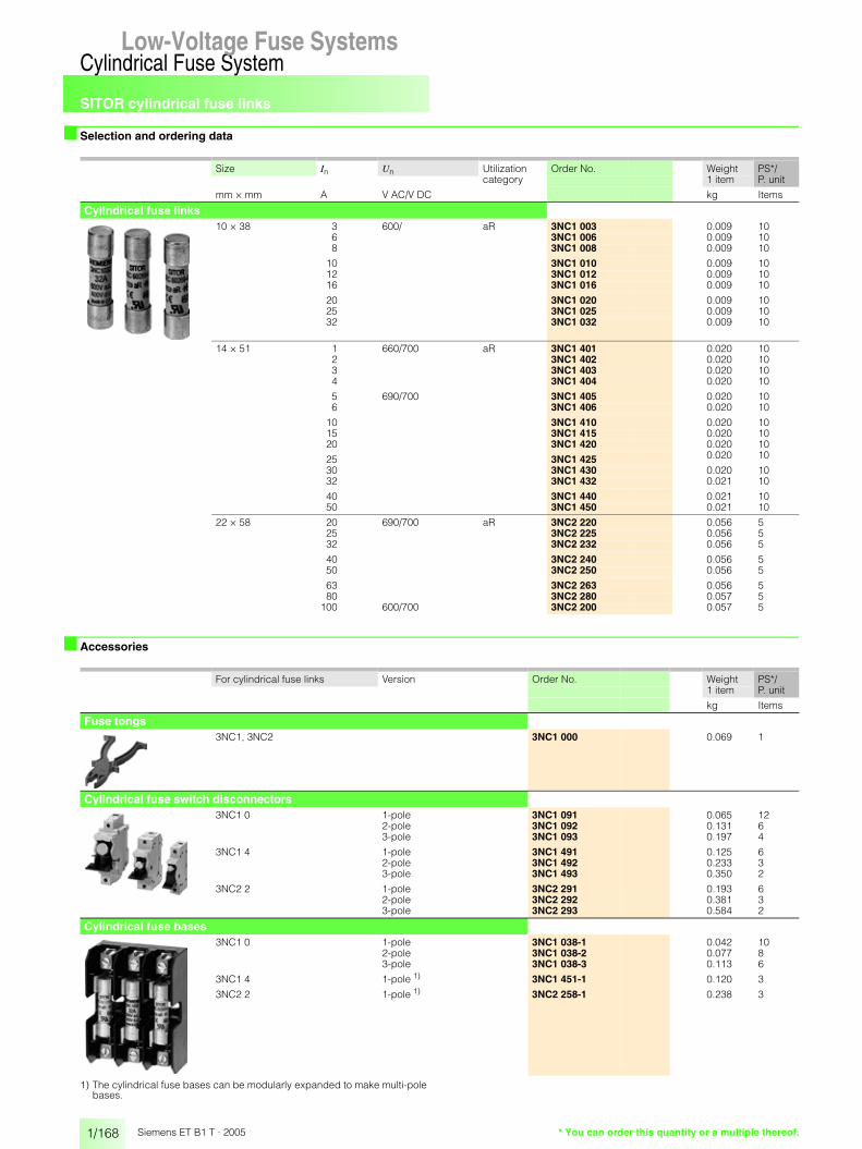
SITOR cylindrical fuse links
1/168
Cylindrical Fuse SystemLow-Voltage Fuse Systems
Siemens ET B1 T · 2005 * You can order this quantity or a multiple thereof.
■ Selection and ordering data
■ Accessories
1) The cylindrical fuse bases can be modularly expanded to make multi-pole bases.
Size In Un Utilization category
Order No. Weight PS*/P. unit1 item
mm × mm A V AC/V DC kg Items
Cylindrical fuse links10 × 38 3 600/ aR 3NC1 003 0.009 10
6 3NC1 006 0.009 108 3NC1 008 0.009 10
10 3NC1 010 0.009 1012 3NC1 012 0.009 1016 3NC1 016 0.009 10
20 3NC1 020 0.009 1025 3NC1 025 0.009 1032 3NC1 032 0.009 10
14 × 51 1 660/700 aR 3NC1 401 0.020 102 3NC1 402 0.020 103 3NC1 403 0.020 104 3NC1 404 0.020 10
5 690/700 3NC1 405 0.020 106 3NC1 406 0.020 10
10 3NC1 410 0.020 1015 3NC1 415 0.020 1020 3NC1 420 0.020 10
25 3NC1 425 0.020 10
30 3NC1 430 0.020 1032 3NC1 432 0.021 10
40 3NC1 440 0.021 1050 3NC1 450 0.021 10
22 × 58 20 690/700 aR 3NC2 220 0.056 525 3NC2 225 0.056 532 3NC2 232 0.056 5
40 3NC2 240 0.056 550 3NC2 250 0.056 5
63 3NC2 263 0.056 580 3NC2 280 0.057 5
100 600/700 3NC2 200 0.057 5
For cylindrical fuse links Version Order No. Weight PS*/P. unit1 item
kg Items
Fuse tongs3NC1, 3NC2 3NC1 000 0.069 1
Cylindrical fuse switch disconnectors3NC1 0 1-pole 3NC1 091 0.065 12
2-pole 3NC1 092 0.131 63-pole 3NC1 093 0.197 4
3NC1 4 1-pole 3NC1 491 0.125 62-pole 3NC1 492 0.233 33-pole 3NC1 493 0.350 2
3NC2 2 1-pole 3NC2 291 0.193 62-pole 3NC2 292 0.381 33-pole 3NC2 293 0.584 2
Cylindrical fuse bases3NC1 0 1-pole 3NC1 038-1 0.042 10
2-pole 3NC1 038-2 0.077 83-pole 3NC1 038-3 0.113 6
3NC1 4 1-pole 1) 3NC1 451-1 0.120 3
3NC2 2 1-pole 1) 3NC2 258-1 0.238 3
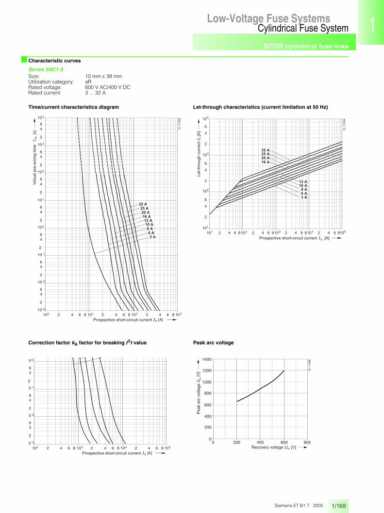
SITOR cylindrical fuse links
1/169
Cylindrical Fuse SystemLow-Voltage Fuse Systems 1
345678910
1213
Siemens ET B1 T · 2005
■ Characteristic curves
Series 3NC1 0Size: 10 mm x 38 mmUtilization category: aRRated voltage: 600 V AC/400 V DCRated current: 3 ... 32 A
Time/current characteristics diagram Let-through characteristics (current limitation at 50 Hz)
Correction factor kA factor for breaking I2t value Peak arc voltage
p
vs
210010 -3
2
46
10 -2
64 1018 2 64 1028 2 4
2
46
10 -1
2
46
10 0
2
46
10 1
2
46
10 2
2
46
10 3
2
46
104
I2_1
1453
6 1038
[s]
[A]
� � � �
� � � �
� � � �
� � � �
� � � �
� � � �
� �
� � �
� � �
Virt
ual p
re-a
rcin
g tim
e
Prospective short-circuit current
� � � � �� � ��
� �
�
�
��
� �
�
� � �
� � �� � �� � � �� � ��
������ �
� �
�
�
�
� �
�
�
�
�
�
�
� �� � � � �
� � � �
� � � �
� �
� � �
� � �
� � � �
� � � �
� �
� � �
� � �
� � � �
� �
� � �
� � �
� � � �
� � � �
� � � �
� � � �
�������������������
� � � � � � � � � � � � � � � � � � � � � � � � � � � � � � � � �
p
21020 -3
2
46
0 -2
64 1038 2 64 1048 2 4
2
46
0 -1
2
46
0 0
6 1058[A]Prospective short-circuit current
0 200 400 600 800
400
800
1200
s
w
1400
1000
600
200
0
I2_1
1456
� �
��
Recovery voltage
Pea
k ar
c vo
ltage
Û

SITOR cylindrical fuse links
1/170
Cylindrical Fuse SystemLow-Voltage Fuse Systems
Siemens ET B1 T · 2005
■ Characteristic curves
Series 3NC1 40, 3NC1 41Size: 14 mm x 51 mmUtilization category: aRRated voltage: 660 V AC/700 V DC (1 ... 4 A); 690 V AC/700 V DC (5 ... 50 A)Rated current: 1 to 10 A
Time/current characteristics diagram Let-through characteristics (current limitation at 50 Hz)
Correction factor kA factor for breaking I2t value Peak arc voltage
p
vs
210010 -3
2
46
10 -2
64 1018 2 64 1028 2 4
2
46
10 -1
2
46
10 0
2
46
10 1
2
46
10 2
2
46
10 3
2
46
104
I2_1
1459
6 1038
[s]
[A]
� � � �
� � �
� � �
� �
� � �
� � �
� � �
Virt
ual p
re-a
rcin
g tim
e
Prospective short-circuit current
101 2 64 108
10
2
4
6
c
p [A]
[A]
101
3 2 64 108 4 2 64 108 5
I2_1
1460
10
2
4
6
10
2
4
6
2
3
4
2 64 8102
� � �
� � � �
Let-
thro
ugh
curr
ent
Prospective short-circuit current
0 100 200 300 400 500 600
1
700 800
A
w � �
I2_1
1461
Cor
rect
ion
fact
or
Recovery voltage
0.2
0.4
0.6
0.8
0 200 400 600 800
400
800
1200
s
w
1400
1000
600
200
0
I2_1
1462
� �
��
Recovery voltage
Pea
k ar
c vo
ltage
Û
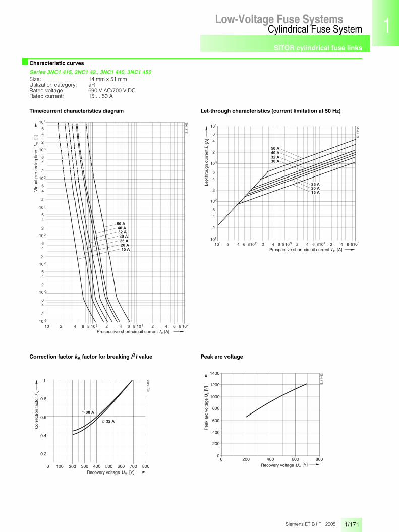
SITOR cylindrical fuse links
1/171
Cylindrical Fuse SystemLow-Voltage Fuse Systems 1
345678910
1213
Siemens ET B1 T · 2005
■ Characteristic curves
Series 3NC1 415, 3NC1 42., 3NC1 440, 3NC1 450Size: 14 mm x 51 mmUtilization category: aRRated voltage: 690 V AC/700 V DCRated current: 15 ... 50 A
Time/current characteristics diagram Let-through characteristics (current limitation at 50 Hz)
Correction factor kA factor for breaking I2t value Peak arc voltage
p
vs
210110 -3
2
46
10 -2
64 1028 2 64 1038 2 4
2
46
10 -1
2
46
10 0
2
46
10 1
2
46
10 2
2
46
10 3
2
46
104
I2_1
1463
6 1048
[s]
[A]
� � � �
� � �
� � � �
� � � �
� � � �
� � � �
� � � �
Virt
ual p
re-a
rcin
g tim
e
Prospective short-circuit current
101 2 64 108
10
2
4
6c
p [A]
[A]
101
3 2 64 108 4 2 64 108 5
I2_1
1464
10
2
4
6
10
2
4
6
2
3
4
2 64 8102
� � � �
� � � �
� � � �
� � � �
� � �
� � � �
� � � �
Let-
thro
ugh
curr
ent
Prospective short-circuit current
0 100 200 300 400 500 600
1
700 800
A
w � �
� � � �
� � � �
I2_1
1465
Cor
rect
ion
fact
or
Recovery voltage
0.2
0.4
0.6
0.8
0 200 400 600 800
400
800
1200
s
w
1400
1000
600
200
0
I2_1
1462
� �
��
Recovery voltage
Pea
k ar
c vo
ltage
Û

SITOR cylindrical fuse links
1/172
Cylindrical Fuse SystemLow-Voltage Fuse Systems
Siemens ET B1 T · 2005
■ Characteristic curves
Series 3NC2 2Size: 22 mm x 58 mmUtilization category: aRRated voltage: 690 V AC/700 V DC (20 ... 80 A)
600 V AC/700 V DC (100 A)Rated current: 20 ... 100 A
Time/current characteristics diagram Let-through characteristics (current limitation at 50 Hz)
Correction factor kA factor for breaking I2t value Peak arc voltage
p
vs
210110 -3
2
46
10 -2
64 1028 2 64 1038 2 4
2
46
10 -1
2
46
10 0
2
46
10 1
2
46
10 2
2
46
10 3
2
46
104
I2_1
1470
6 1048
[s]
[A]
� � � � �
� � �
� � � �
� � � �
� � �
� � � �
� � � �
� � � �
Virt
ual p
re-a
rcin
g tim
e
Prospective short-circuit current
102 2 64 108
10
2
4
6
2
4
6
3
c
p [A]
[A]
104
102
3 2 64 108 4 2 64 108 5 2 4
� � � �
I2_1
1471
� � � �
� � � �
� � �
� � � �
� � � � �
� � �
� � � �
Let-
thro
ugh
curr
ent
Prospective short-circuit current
0 100 200 300 400 500 600
1
700 800
A
w � �
I2_1
1472
Cor
rect
ion
fact
or
Recovery voltage
0.2
0.4
0.6
0.8
0 200 400 600 800
400
800
1200
s
w
1400
1000
600
200
0
I2_1
1466
� �
��
Recovery voltage
Pea
k ar
c vo
ltage

SITOR cylindrical fuse links
1/173
Cylindrical Fuse SystemLow-Voltage Fuse Systems 1
345678910
1213
Siemens ET B1 T · 2005
■ Dimensional drawings
Cylindrical fuse links
Cylindrical fuse switch disconnectors
38
I2_11377
Ø10
,2
9,5
3NC1 0
10,2
9,5
6,5
9,53538
I2_11378
3NC1 1
10
14,3
I2_11379
51
3NC1 4, 3NC1 5
16
Ø22
,2
I2_11380
58
3NC2 2
���
���
��
���� ���������
�
���
����
3NC1 09.
�� ���
���
���
����
��
����
����
��
3NC1 49.
��
���
���
�� ��
��
��
�����
����
3NC2 29.

SITOR cylindrical fuse links
1/174
Cylindrical Fuse SystemLow-Voltage Fuse Systems
Siemens ET B1 T · 2005
■ Dimensional drawings
Cylindrical fuse bases
������ ����
������
��
��
���
���
3NC1 038-1 to 3NC1 038-3
���
���
����
����
�
��
��
��
3NC1 451-2
��
���
���
����
����
����
�
����
3NC2 258-1

Bases for cylindrical fuses
1/175
Cylindrical Fuse SystemLow-Voltage Fuse Systems 1
345678910
1213
Siemens ET B1 T · 2005
Low-Voltage Fuse Systems
■ Benefits• IEC 60269-1, -2, -2-1• Rated voltage 400 V AC and 690 V AC• No switching under load
• Off-circuit changing of fuses• Without or with signal detector for signaling the tripping of the
fuse link
■ Technical specifications
1) The U Approval only applies to bases for cylindrical fuses without signal detectors; approval is expected to be available soon for bases with signal detectors.
Fuse bases for cylindrical fusesType 3NW7 3 3NW7 0 3NW7 1 3NW7 2
Size mm x mm 8 x 32 10 x 38 14 x 51 22 x 58
Standards IEC 60269-1, -2, -2-1NF C 60-200, 63-210, 63-211NBN C 63269-2en-2-1CEI 32-4, -12
UL Approval U 1) available soon
CSA Approval cU s cU available soon
Utilization category acc. to EN 60947-3 AC 20B (switching without load), DC 20B
Rated voltage Un V AC 400 690
Rated voltage according to UL/CSA V AC 400 600
Rated current In A AC 0.5 ... 100
Mounting position any, but preferably vertical
Degree of protection according to IEC 60529 in the distribu-tion board
IP20
Terminal version anti-slip terminals
Conductor cross-sections
rigid, solid mm2 1.5 ... 10 2.5 ... 10 4 ... 10stranded mm2 2.5 ... 16 2.5 ... 25 4 ... 50finely stranded with end sleeve mm2 1.5 ... 10 2.5 ... 16 4 ... 35
Conductor cross-sections acc. to UL/CSAAWG (American wire gauge )
10 ... 18 solid 6 ... 10 solid and stranded
available soon
Stripped lengths mm 11 14 20
Tightening torque Nm 2.0 2.5

Bases for cylindrical fuses
1/176
Cylindrical Fuse SystemLow-Voltage Fuse Systems
Siemens ET B1 T · 2005 * You can order this quantity or a multiple thereof.
■ Selection and ordering data
In For fuse links MW Order No. Weight PS*/P. unitSize 1 item
A mm x mm kg Items
Draw-out typewithout signal detector
1-pole20 8 x 32 1 3NW7 310 0.058 132 10 x 38 1 3NW7 011 0.080 150 14 x 51 1.5 3NW7 111 0.095 1
100 22 x 58 2 3NW7 211 0.145 1
1-pole + N20 8 x 32 2 3NW7 350 0.120 132 10 x 38 2 3NW7 051 0.167 150 14 x 51 3 3NW7 151 0.215 1
100 22 x 58 4 3NW7 251 0.330 1
2-pole20 8 x 32 2 3NW7 320 0.112 132 10 x 38 2 3NW7 021 0.162 150 14 x 51 3 3NW7 121 0.195 1
100 22 x 58 4 3NW7 221 0.300 1
3-pole20 8 x 32 3 3NW7 330 0.167 132 10 x 38 3 3NW7 031 0.243 150 14 x 51 4.5 3NW7 131 0.295 1
100 22 x 58 6 3NW7 231 0.691 1
3-pole + N20 8 x 32 4 3NW7 360 0.227 132 10 x 38 4 3NW7 061 0.327 150 14 x 51 6 3NW7 161 0.315 1
100 22 x 58 8 3NW7 261 0.475 1
with signal detector
1-pole20 8 x 32 1 3NW7 312 0.058 132 10 x 38 1 3NW7 012 0.080 150 14 x 51 1.5 3NW7 112 0.095 1
100 22 x 58 2 3NW7 212 0.145 1
1-pole + N20 8 x 32 2 3NW7 352 0.120 132 10 x 38 2 3NW7 052 0.167 150 14 x 51 3 3NW7 152 0.215 1
100 22 x 58 4 3NW7 252 0.330 1
2-pole20 8 x 32 2 3NW7 322 0.112 132 10 x 38 2 3NW7 022 0.162 150 14 x 51 3 3NW7 122 0.195 1
100 22 x 58 4 3NW7 222 0.300 1
3-pole20 8 x 32 3 3NW7 332 0.167 132 10 x 38 3 3NW7 032 0.243 150 14 x 51 4.5 3NW7 132 0.295 1
100 22 x 58 6 3NW7 232 0.480 1
3-pole + N20 8 x 32 4 3NW7 362 0.227 132 10 x 38 4 3NW7 062 0.327 150 14 x 51 6 3NW7 162 0.315 1
100 22 x 58 8 3NW7 262 0.475 1
Auxiliary switch
for indicating disconnection of the fuse linkSolely for application of Striker fuse links(not currently available in the Siemens manufacturing program)for retrofitting with factory-fitted brackets, 0.5 MW.contact: 250 V AC, 5 A, Minimum contact load: 12 V, 25 mA
for fuse bases 14 x 51 0.5 3NW7 901 0.050 1for fuse bases 22 x 58 3NW7 902 0.050 1
�
�
�
�
�
�
�
�
�
�
�
�
�
�
�
�
�
�
�
�
�
�
�
�
�
�
�
�
�
�
�
�
�
�
�
�
�
�
�
�
�
�
�
�
�
�
�
�

Bases for cylindrical fuses
1/177
Cylindrical Fuse SystemLow-Voltage Fuse Systems 1
345678910
1213
Siemens ET B1 T · 2005
■ Dimensional drawings
3NW7 installation fuse bases for cylindrical fuse links
���
�
���
��
������
��
��
�� �� ��
Size 8 mm × 32 mm3NW7 3
���
�
���
��
������
��
��
�� �� ��
Size 10 mm × 38 mm3NW7 0
��
�
���
��
��
��
����������
�� �� ���
��
Size 14 mm × 51 mm3NW7 1
���������
��
�
���
��
���
�����
��
�� �� ��� ���
Size 22 mm × 58 mm3NW7 2
���
�
�� ��
�
���
���
���
3NW7 901auxiliary switches
���
�
�� ��
�
���
���
���
3NW7 902auxiliary switches

Notes
1/178
Cylindrical Fuse SystemLow-Voltage Fuse Systems
Siemens ET B1 T · 2005

Product overview
1/179
SITOR Fuse Links for Special ApplicationsLow-Voltage Fuse Systems 1
345678910
1213
Siemens ET B1 T · 2005
Low-Voltage Fuse Systems
■ Overview
for rectifiers in electrolysis systems
for SITOR thyristor sets
for railway supply rectifiers

for rectifiers in electrolysis systems
1/180
SITOR Fuse Links for Special ApplicationsLow-Voltage Fuse Systems
Siemens ET B1 T · 2005 * You can order this quantity or a multiple thereof.
■ Technical specifications
■ Selection and ordering data
1) Maximum tightening torque: - M10 thread (with indicator): 40 Nm - M10 capped thread: 50 Nm, depth of screw entry � 9 mm- M24 × 1.5 thread: 60 Nm.
2) Temperature of water-cooled power rail max. +45 °C.3) Maximum tightening torque: M10 capped thread: 35 Nm, depth of screw entry � 9 mm.4) Cooling air speed � 2 m/s.5) Bottom (cooled) connection max. +60 °C, top connection (M10) max. +110 °C.
Type 3NC5 531 1) 3NC5 841 1) 3NC5 840 1) 3NC5 838 1)
Utilization category (IEC 60269) aR
Rated voltage Un V AC 800 1000
Rated current In A 350 2) 630 2) 600 2) 800 2)
Melting I2t value I2ts (tvs = 1 ms) A2s 66000 185000 360000
Breaking I2t value I2tA at Un A2s 260000 888000 1728000
Temperature rise at In (body center) K 200 110 130
Power dissipation at In W 80 145 150 170
Varying load factor WL 0.9
Weight approx. kg 0.67 1.2 1.4 1.2
Type 3NE9 440-6 3NE9 450 3NE6 437 3NE6 444 3NE9 450-7 3NE6 437-7
Utilization category (IEC 60269) gR aR
Rated voltage Un V AC 600 900 600 900
Rated current In 3) A 850 1250 4) 710 4) 900 4) 1250 5) 710 5)
Melting I2t value I2ts (tvs = 1 ms) A2s 400000 100000 400000 100000
Breaking I2t value I2tA at Un A2s 2480000 620000 1920000 2480000 620000
Temperature rise at In (body center) K 74 80 105 110
Power dissipation at In W 85 210 150 170 210 150
Varying load factor WL 1.0 0.9
Weight approx. kg 1.0 1.1 1.0
In Un Utilization category
Order No. Weight PS*/P. unit1 item
A V AC kg Items
for rectifiers in electrolysis systemsfor screwing onto water-cooled power rails
350 800 aR 3NC5 531 0.671 3600 1000 3NC5 840 1.400 3630 800 3NC5 841 1.180 3800 1000 3NC5 838 1.190 3
710 900 3NE6 437-7 1.160 31250 600 3NE9 450-7 1.240 3
for air-cooled rectifiers in electrolysis systems710 800 gR 3NE6 437 1.090 3850 1000 3NE9 440-6 1.080 3900 1000 aR 3NE6 444 1.170 3
1250 800 3NE9 450 1.110 3

for rectifiers in electrolysis systems
1/181
SITOR Fuse Links for Special ApplicationsLow-Voltage Fuse Systems 1
345678910
1213
Siemens ET B1 T · 2005
■ Characteristic curves
Series 3NC5 531, 3NC5 8..Utilization category: aRRated voltage: 800 V AC(350 A, 600 A),
1000 V AC (600 A, 800 A)Rated current: 350 ... 800 ATime/current characteristics diagram
Correction factor kA for breaking I2t value
Let-through characteristics (current limitation at 50 Hz)
Peak arc voltage
p
vs
210210 -3
2
46
10 -2
64 1038 2 64 1048 2 4
2
46
10 -1
2
46
10 0
2
46
10 1
2
46
10 2
2
46
10 3
2
46
104
I2_1
1432
6 1058
[s]
[A]
� � � �� � � � �
� � � � �
� � � � �
Virt
ual p
re-a
rcin
g tim
e
Prospective short-circuit current
0 200 400 600
1
800 1000
A
w [V]
I2_1
1434
� � � � �
� � � � �� � � � �
� � � �
Cor
rect
ion
fact
or
0.8
0.6
0.4
0.2
Recovery voltage
c
p [A]
[A] I2
_114
33
103
10
2
4
6
2
4
6
4
105
103
105 2 4104 2 64 82 64 8
� � � � �
� � � � �
� � � � �
� � � �
Let-
thro
ugh
curr
ent
Prospective short-circuit current
Unlimited peak values:DC component 50 %DC component 0 %
0 200 400 600 800 1000 1200
400
1200
1600
2000
0
s
w � � �
���
I2_1
1435
200
600
800
1000
1400
1800
� � � � �
� � � �
� � � � �
� � � � �
Pea
k ar
c vo
ltage
Recovery voltage
Û
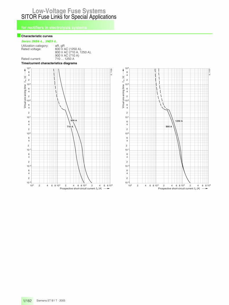
for rectifiers in electrolysis systems
1/182
SITOR Fuse Links for Special ApplicationsLow-Voltage Fuse Systems
Siemens ET B1 T · 2005
■ Characteristic curves
Series 3NE6 4.., 3NE9 4..Utilization category: aR, gRRated voltage: 600 V AC (1250 A),
800 V AC (710 A, 1250 A), 900 V AC (710 A)
Rated current: 710 ... 1250 ATime/current characteristics diagrams
p
vs
210210 -3
2
46
10 -2
64 1038 2 64 1048 2 4
2
46
10 -1
2
46
10 0
2
46
10 1
2
46
10 2
2
46
10 3
2
46
104
I2_1
1436
6 1058
[s]
[A]
� � � �
� � � � �
Virt
ual p
re-a
rcin
g tim
e
Prospective short-circuit current p
vs
210210 -3
2
46
10 -2
64 1038 2 64 1048 2 4
2
46
10 -1
2
46
10 0
2
46
10 1
2
46
10 2
2
46
10 3
2
46
104
I2_1
1437
6 1058
[s]
[A]
� � � � � �
� � � � �
Virt
ual p
re-a
rcin
g tim
e
Prospective short-circuit current

for rectifiers in electrolysis systems
1/183
SITOR Fuse Links for Special ApplicationsLow-Voltage Fuse Systems 1
345678910
1213
Siemens ET B1 T · 2005
■ Characteristic curves
Series 3NE6 4.., 3NE9 4..Utilization category: aR, gRRated voltage: 600 V AC (1250 A),
800 V AC (710 A, 1250 A), 900 V AC (710 A)
Rated current: 710 ... 1250 ALet-through characteristics (current limitation at 50 Hz)
c
p [A]
[A] I2
_114
38
103
10
2
4
6
2
4
6
4
105
103
105 2 4104 2 64 82 64 8
� � � � �
� � � � � � � � � � �
Let-
thro
ugh
curr
ent
Prospective short-circuit current
Unlimited peak values:DC component 50 %DC component 0 %
Correction factor kA for breaking I2t value Peak arc voltage
0 200 400 600
1
800 1000
A
w [V]
I2_1
1439
� � � � �
� � � �
� � � � � �
� � � � �
Cor
rect
ion
fact
or
0.8
0.6
0.4
0.2
Recovery voltage
0 200 400 600 800 1000 1200
400
1200
1600
2000
0
s
w � � �
���
I2_1
1440
200
600
800
1000
1400
1800
� � � �
� � � � �
� � � � �
� � � � � �
Pea
k ar
c vo
ltage
Recovery voltage
Û

for rectifiers in electrolysis systems
1/184
SITOR Fuse Links for Special ApplicationsLow-Voltage Fuse Systems
Siemens ET B1 T · 2005
■ Dimensional drawings
3NC5 531 3NC5 8..
Type Dimensions
a b c
3NC5 838, 3NC5 841
98 88.5 25
3NC5 844 119 109.5 20.5
3NE6 4.., 3NE9 4.., 3NE6 4..-7, 3NE9 4..-7
Type Dimensions
a b
3NE6 437,3NE9 440-6,3NE9 450
89 76
3NE6 444 99 86
50
M10
M10
2850
SW4191
924,5
0,3
I2_11369
73
M10
40M
24
M10
SW41 ba c
11I2_11370
10
70
M10
28
70 ba
10
81,5 I2_1
1371
70
M10
28
7010
012
583
10
11
10
81,575,5
I2_1
1372

for SITOR thyristor sets
1/185
SITOR Fuse Links for Special ApplicationsLow-Voltage Fuse Systems 1
345678910
1213
Siemens ET B1 T · 2005
■ Technical specifications
■ Selection and ordering data
1) Maximum tightening torque: M10 capped thread: 35 Nm, depth of screw entry � 9 mm.2) Cooling air speed � 0.5 m/s. In case of natural air cooling, reduction of 5%.
Type 3NE4 117-5 3NE4 121-5 3NE4 146-5 3NE3 525-5 1) 3NE3 535-5 1)
Utilization category (IEC 60269) gR aR
Rated voltage Un V AC 1000 800 1000
Rated current In A 50 100 170 200 2) 450 2)
Melting I2t value I2ts (tvs = 1 ms) A2s 135 900 7370 7150 64500
Breaking I2t value I2tA at Un A2s 1100 7400 60500 44000 395000
Temperature rise at In (body center) K 95 135 142 75 130
Power dissipation at In W 20 35 43 50 90
Varying load factor WL 0.85
Weight approx. kg 0.28 0.7
Type 3NE4 327-6B 1) 3NE4 330-6B 1) 3NE4 333-6B 1) 3NE4 334-6B 1) 3NE4 337-6 1)
Utilization category (IEC 60269) aR
Rated voltage Un V AC 800
Rated current In A 250 315 450 500 710
Melting I2t value I2ts (tvs = 1 ms) A2s 3600 7400 29400 42500 142000
Breaking I2t value I2tA at Un A2s 29700 60700 191000 276000 923000
Temperature rise at In (body center) K 175 170 190 195 170
Power dissipation at In W 105 120 140 155
Varying load factor WL 0.85 0.95
Weight approx. kg 0.65
In Un Utilization category
Order No. Weight PS*/P. unit1 item
A V AC kg Items
for SITOR 6QG10 thyristor sets 200 1000 aR 3NE3 525-5 0.744 3450 3NE3 535-5 0.746 3
for SITOR 6QG11 thyristor sets 50 1000 gR 3NE4 117-5 0.303 1/3
100 aR 3NE4 121-5 0.309 1/3170 800 3NE4 146-5 0.311 1/3
for SITOR 6QG12 thyristor sets 250 800 aR 3NE4 327-6B 0.692 3315 3NE4 330-6B 0.688 3450 3NE4 333-6B 0.690 3
500 3NE4 334-6B 0.688 3710 3NE4 337-6 0.689 3
* You can order this quantity or a multiple thereof.

for SITOR thyristor sets
1/186
SITOR Fuse Links for Special ApplicationsLow-Voltage Fuse Systems
Siemens ET B1 T · 2005
■ Characteristic curves
Series 3NE3 5.5-5, 3NE4 1..-5Utilization category: aR, gRRated voltage: 800 V AC (170 A)
1000 V AC (50 A, 100 A, 200 A, 450 A)Rated current: 50 ... 450 ATime/current characteristics diagram
Correction factor kA for breaking I2t value
Let-through characteristics (current limitation at 50 Hz)
Peak arc voltage
p
vs
210110 -3
2
46
10 -2
64 1028 2 64 1038 2 4
2
46
10 -1
2
46
10 0
2
46
10 1
2
46
10 2
2
46
10 3
2
46
104
I2_1
1441
6 1048
[s]
[A]
� � � � �
� � � � � � � � � � � � � � � � � �
Virt
ual p
re-a
rcin
g tim
e
Prospective short-circuit current
0 200 400 600
1
800 1000
A
w [V]
I2_1
1443
� � � � � � �
� � � � �
� � � � � � �
Cor
rect
ion
fact
or
0.8
0.6
0.4
0.2
Recovery voltage
102 2 64 108
10
2
4
6
3
c
p [A]
[A]
102
3 2 64 108 4 2 64 108 5 2 4
I2_1
1442
10
2
4
6
4
2
4
� � � � �
� � � � �
� � � � �
� � � �
� � � �
Let-
thro
ugh
curr
ent
Prospective short-circuit current
Unlimited peak values:DC component 50 %DC component 0 %
0 200 400 600 800 1000 1200
400
1200
1600
2000
0
s
w � � �
���
I2_1
1444
200
600
800
1000
1400
1800
� � � � �
� � � � �
ÛP
eak
arc
volta
ge
Recovery voltage

for SITOR thyristor sets
1/187
SITOR Fuse Links for Special ApplicationsLow-Voltage Fuse Systems 1
345678910
1213
Siemens ET B1 T · 2005
■ Characteristic curves
Series 3NE4 3..-6B, 3NE4 337-6Utilization category: aRRated voltage: 800 V ACRated current: 250 ... 710 ATime/current characteristics diagram
Correction factor kA for breaking I2t value
Let-through characteristics (current limitation at 50 Hz)
Peak arc voltage
p
vs
210210 -3
2
46
10 -2
64 1038 2 64 1048 2 4
2
46
10 -1
2
46
10 0
2
46
10 1
2
46
10 2
2
46
10 3
2
46
104
I2_1
1445
6 1058
[s]
[A]
� � � � �
� � � � �
� � � �
� � � � �
� � � � �
Virt
ual p
re-a
rcin
g tim
e
Prospective short-circuit current
0 100 200 300 400 500 600
1
700 800
A
w � � �
� � � � �
� � � �
Cor
rect
ion
fact
or
Recovery voltage
0.2
0.4
0.6
0.8
c
p [A]
[A] I2
_114
46
103
10
2
4
6
2
4
6
4
105
103
105 2 4104 2 64 82 64 8
� � � � �
� � � � �
� � � �
� � � � �
� � � � �
Let-
thro
ugh
curr
ent
Prospective short-circuit current
Unlimited peak values:DC component 50 %DC component 0 %
0 200 400 600 800 1000 1200
400
1200
1600
2000
0
s
w � � �
���
I2_1
1448
200
600
800
1000
1400
1800
Pea
k ar
c vo
ltage
Recovery voltage
Û

for SITOR thyristor sets
1/188
SITOR Fuse Links for Special ApplicationsLow-Voltage Fuse Systems
Siemens ET B1 T · 2005
■ Dimensional drawings
3NE3 5..-5 3NE4 3..-6B, 3NE4 337-6
3NE4 1..-5
775515
60
73
60
M10
20
10,5
82,5
I2_11373
I2_1
1374
60
M10
20
60 7677
15
6647
52
53
3010
54
57
62
2640 10
,4I2
_113
75

for railway supply rectifiers
1/189
SITOR Fuse Links for Special ApplicationsLow-Voltage Fuse Systems 1
345678910
1213
Siemens ET B1 T · 2005
■ Technical specifications
■ Selection and ordering data
Type 3NC7 327-2 3NC7 331-2
Utilization category (IEC 60269) aR
Rated voltage Un V AC 680
Rated current In A 250 350
Melting I2t value I2ts (tvs = 1 ms) A2s 244000 550000
Breaking I2t value I2tA at Un A2s 635000 1430000
Temperature rise at In (body center) K 45 66
Power dissipation at In W 25 32
Varying load factor WL 0.9
Weight approx. kg 0.7
In Un Utilization category
Order No. Weight PS*/P. unit1 item
A V AC kg Items
for railway supply rectifiers250 680 aR 3NC7 327-2 0.725 3350 3NC7 331-2 0.740 3
* You can order this quantity or a multiple thereof.

for railway supply rectifiers
1/190
SITOR Fuse Links for Special ApplicationsLow-Voltage Fuse Systems
Siemens ET B1 T · 2005
■ Characteristic curves
Series 3NC7 3..-2Utilization category: aRRated voltage: 680 V ACRated current: 250 A, 350 ATime/current characteristics diagram
Correction factor kA for breaking I2t value
Let-through characteristics (current limitation at 50 Hz)
Peak arc voltage
p
vs
210210 -3
2
46
10 -2
64 1038 2 64 1048 2 4
2
46
10 -1
2
46
10 0
2
46
10 1
2
46
10 2
2
46
10 3
2
46
104
I2_1
1449
6 1058
[s]
[A]
� � � � �
� � � � �
Virt
ual p
re-a
rcin
g tim
e
Prospective short-circuit current
0 100 200 300 400 500 600
1
700 800
A
w � � �
Cor
rect
ion
fact
or
Recovery voltage
0.2
0.4
0.6
0.8
c
p [A]
[A] I2
_114
50
103
10
2
4
6
2
4
6
4
105
103
105 2 4104 2 64 82 64 8
� � � � �
� � � � �
Let-
thro
ugh
curr
ent
Prospective short-circuit current
Unlimited peak values:DC component 50 %DC component 0 %
0 200 400 600 800 1000 1200
400
1200
1600
2000
0
s
w � � �
���
I2_1
1452
200
600
800
1000
1400
1800
ÛP
eak
arc
volta
ge
Recovery voltage

for railway supply rectifiers
1/191
SITOR Fuse Links for Special ApplicationsLow-Voltage Fuse Systems 1
345678910
1213
Siemens ET B1 T · 2005
■ Dimensional drawings
3NC7 3..-2
12,5
57
68
119
57307 79
10,5
10,5
I2_1
1376

Technical explanations
1/192
General Data for SITOR Semiconductor Safety FusesLow-Voltage Fuse Systems
Siemens ET B1 T · 2005
Low-Voltage Fuse Systems
■ OverviewFuse links are selected according to rated voltage, rated current, breaking I2t value I2tA and varying load factor, taking into account any further conditions specified. Unless stated otherwise, all of the following data refer to AC operation from 45 Hz to 62 Hz.
Rated voltage Un
The rated voltage of a SITOR fuse link is the voltage specified as the r.m.s. value of the AC voltage on the fuse link and in the order and configuration data and the characteristics.Always ensure that the rated voltage of the fuse link you select is such that the fuse link will reliably quench the voltage driving the short-circuit current. The driving voltage must not exceed the value Un + 10 %. Please note that the supply voltage Uv0 of a power con-verter can also be increased by 10 %. If, in the shorted circuit, two arms of a converter connection are connected in series, and if the short-circuit current is sufficiently high, it can be assumed that volt-age sharing is uniform. It is essential to observe the instructions in ’Series connection of fuse links’ on page 1/198.
Rectifier operationWith converter equipment that can only be used for rectifier opera-tion, the supply voltage Uv0 is the driving voltage.
Inverter operationWith converter equipment that can also be used for inverter opera-tion, shoot-throughs may occur as faults. In this case, the driving voltage UWK in the shorted circuit is the sum of the infeed direct volt-age (e.g. the e.m.f. of the DC generator) and the AC-line supply volt-age. When rating a fuse link, this sum can be replaced by an AC voltage whose r.m.s. value is 1.8 times that of the AC-line supply voltage (UWK = 1.8 Uv0). The fuse links must be rated so that they reliably quench the voltage UWK.
Rated current In, current carrying capacityThe rated current of a SITOR fuse link is the current specified as r.m.s. value of the alternating current for the frequency range 45 Hz to 62 Hz in the Selection and ordering data and Characteristics , as well as on the fuse link itself.When operating fuse links with rated current, the following are considered normal operating conditions:• Natural air cooling with an ambient temperature of +45 °C• Conductor cross-sections equal test cross-sections (see Test
cross-sections table), for operation in LV HRC fuse bases and switch-disconnectors, please refer to the Selection and ordering data
• Conduction angle of a half-period 120 °el• Continuous load maximum with rated current
For operating conditions that deviate from the above, the permissi-ble load current In’ of the SITOR fuse link can be determined using the following formula:In’ = ku x kq x kl x kl x WL x InwherebyIn rated current of the fuse link 1)
ku correction factor for ambient temperature (page 1/193)kq correction factor for conductor cross-section (page 1/193)kl correction factor for conduction angle (page 1/193)kl correction factor for increased air cooling (page 1/193)WL varying load factor (page 1/194)
Test cross-sections
1) When using SITOR fuse links in LV HRC fuse bases according to IEC/EN 60269-2-1 and fuse switch-disconnectors and switch disconnec-tors with fuses, please also refer to the data in the selection and ordering data.
Rated current In
Test cross-sections
(series 3NC1 0, 3NC1 1, 3NC1 4, 3NC1 5, 3NC2 2, 3NE1 ..., 3NE8 0.., 3NE4 1)
(all other series)
A Cu mm2 Cu mm2
10 1.0 –16 1.5 –20 2.5 45
25 4 4535 6 4540 10 45
50 10 4563 16 4580 25 45
100 35 60125 50 80160 70 100
200 95 125224 – 150250 120 185
315 2 x 70 240350 2 x 95 260400 2 x 95 320
450 2 x 120 320500 2 x 120 400560 2 x 150 400
630 2 x 185 480710 2 x (40 x 5) 560800 2 x (50 x 5) 560
900 2 x (80 x 4) 7201000 – 7201250 – 960

Technical explanations
1/193
General Data for SITOR Semiconductor Safety FusesLow-Voltage Fuse Systems 1
345678910
1213
Siemens ET B1 T · 2005
■ Overview
Correction factor for ambient temperature ku
The influence of the ambient temperature on the permissible load of the SITOR fuse links is taken into account using the correction factor ku as shown in the following graph.
Correction factor for conductor cross-section kq
The rated current of the SITOR fuse links applies to operation with conductor cross-sections that correspond to the respective test cross-section (see the table on page 1/192).In the case of reduced conductor cross-sections, the correction fac-tor kq, must be used as shown in the following graph.
a = reduction of cross-section of one connection
b = reduction of cross-section of both connections
Correction factor for conduction angle kl
The rated current of the SITOR fuse links is based on a sinusoidal alternating current (45 Hz to 62 Hz). However, in converter opera-tion, the arm fuses are loaded with an intermittent current, whereby the conduction angle is generally 180 °el or 120 °el. With this load current wave form, the fuse link can still carry the full rated current. In the case of smaller conduction angles, the current must be reduced in accordance with the following graph.
Correction factor for increased air cooling kl
In the case of increased air cooling, the current carrying capacity of the fuse link increases with the air speed, air speeds > 5 m/s do not effect any significant further increase of current carrying capacity.
–40 –20 0 +20 +40 +60 +80� �
u
Ambient temperature
Cor
rect
ion
fact
or
0.8
0.9
1.0
1.1
1.2
AD
A94
-505
4
�
q
100 80 60 50 40 30 20 15 10
�
�
Connection cross-section(as a % of the test cross-section)
Cor
rect
ion
fact
or
1.00
0.95
0.90
0.85
0.80
0.75
0.70
0.65 AD
A94
-505
7
30 45 60 90 120 180 240
� � �
360
Valve conducting period
Cor
rect
ion
fact
or
0.5
0.6
0.7
0.8
0.9
1.0
1.1
AD
A94
-505
5b
0 2 4
� �
l
6
Air velocity
Cor
rect
ion
fact
or
1.0
1.1
1.2
1.4
1.3
AD
A94
-505
6b

Technical explanations
1/194
General Data for SITOR Semiconductor Safety FusesLow-Voltage Fuse Systems
Siemens ET B1 T · 2005
■ Overview
Varying load factor WLThe varying load factor WL is a reduction factor by which the non-aging current carrying capacity of the fuse links can be determined for any load cycles. Due to their design, the SITOR fuse links have a range of different varying load factors. In the fuse link characteris-tics, the respective varying load factor WL for >10,000 load changes (1 hour "ON", 1 hour "OFF") is specified for the expected operating time of the fuse links. In the event of a lower number of load changes
during the expected operating time, it may be possible to use a fuse link with a smaller varying load factor WL as shown in the following graph.In the case of uniform loads (no load cycles and no shutdowns), the varying load factor can be taken as WL = 1. For load cycles and shutdowns that last longer than 5 min. and are more frequent than once a week, you need to select the varying load factor WL specified in the characteristics of the individual fuse links.
Waveform of the varying load factor WL for load cycles
Fuse currents for operation in power converterThe r.m.s. value of the fuse current can be calculated for the most common converter connections from the (smoothed) direct
current Id or the conductor current IL according to the following table.
101 2 5 102 2 5 103 2 5 104 2 5 105
� ����/
LAn
Permissible number of load cycles
0.6
0.7
0.8
1.1
0.9
1.0 1.0
0.95
0.9
0.85
0.8
AD
A94
-505
8b
Converter connection r.m.s. value of the conductor current(phase fuse)
r.m.s. value of the branch-circuit current(arm fuse)
One-pulse center tap connection (M1) 1.57 Id –
Double-pulse center tap connection (M2) 0.71 Id –
Three-pulse center tap connection (M3) 0.58 Id –
Six-pulse center tap connection (M6) 0.41 Id –
Double three-pulse center tap connection (parallel) (M3.2) 0.29 Id –
Two-pulse bridge connection (B2) 1.0 Id 0.71 IdSix-pulse bridge connection (B6) 0.82 Id 0.58 IdSingle-phase bidirectional connection (W1) 1.0 IL 0.71 IL

Technical explanations
1/195
General Data for SITOR Semiconductor Safety FusesLow-Voltage Fuse Systems 1
345678910
1213
Siemens ET B1 T · 2005
■ Overview
I2t valuesIn the event of a short-circuit, the current of the fuse link increases during melting time ts up to let-through current Ic (melting current peak).During the arc quenching time tL, the electric arc develops and the short-circuit current is quenched (see following graph).
Current path when switching fuse links
The integral of the current squared over the entire switching period(ts+tL), in other words, the breaking I2t value, determines the heat to be fed to the semiconductor device that is to be protected during the breaking procedure.In order to ensure sufficient protection, the breaking I2t value of the fuse link must be smaller than the I2t value of the semiconductor de-vice. As the temperature increases, i.e. preloading increases, the breaking I2t value of the fuse link decreases almost in the same way as the I 2t value of a semiconductor device, so that it is enough to compare the I2t values in a non-loaded (cold) state.The breaking I2t value (I2tA) is the sum of the melting I2t value (I2ts) and the quenching I2t value(I2tL).
(semiconductor, tvj = 25°C,
tp = 10 ms) > (fuse link)
Melting I 2t value I 2tsThe melting I 2t value can be calculated for the value pairs of the time/current characteristic curve of the fuse link for any periods.As the melting time decreases, the melting I 2t value tends towards a lower limit value at which almost no heat is dissipated from the bottleneck of the fuse-element to the environment during the melting process. The melting I 2t values specified in the Selection and order-ing data and in the characteristics correspond to the melting time tvs = 1 ms.
Quenching I2t value I2tLWhile the melting I2t value is a characteristic of the fuse link, the quenching I2t value depends on circuit data, such as• the recovery voltage Uw • the power factor j of the shorted circuit• the prospective current Ip (current at the installation point of the
fuse link if this is bridged)The maximum quenching I 2t value is reached at a current of 10 x In to 30 x In, depending on the fuse type.
Breaking I2t value I2tA, correction factor kA
The breaking I2t values of the fuse link are specified in the charac-teristics for the rated voltage Un. In order to determine the breaking I2t value for recovery voltage Uw the correction factor kA must be taken into account.I2tA (for Uw) = I2tA (for Un) x kA
The characteristics "correction factor kA" (see the following graph) is specified in the characteristics for the individual fuse series. The breaking I2t values determined in this way apply for prospective currents Ip � 10 x In and power factor = 0.35.
Correction factor kA for breaking I 2t value
Example: Series 3NE8 0..
Taking into account the recovery voltage Uw
The recovery voltage Uw is derived from the voltage driving the short-circuit current. For most faults, the driving voltage is equal to the supply voltage Uv0, however, for shoot-throughs it is 1.8 times the value for the supply voltage Uv0 (see rated voltage, page 1/192). If the shorted circuit contains two arms of a converter connection and thus two fuse links in series, and if the short-circuit current is suf-ficiently high (see series connection, page 1/198) it can be assumed that there is a uniform voltage sharing, i.e. Uw = 0.5 x Uv0 or, in the case of shoot-throughs Uw = 0.9 x Uv0.
Influence of the power factorThe specifications in the characteristics for the breaking I2t values (I2tA) refer to a power factor = 0.35 (exception: for SITOR fuse links 3NC5 8.., 3NE6 4.., 3NE9 4.. the power factor = 0.2 applies).The dependence of the breaking I2t values on the power factor at 1.0 x Un and at 0.5 x Un is shown in the following graph.
Dependence of breaking I 2t value I 2tA of SITOR fuse links on power factor
at 1.0 Un
at 0.5 Un
a = for SITOR fuse links 3NC5 8.., 3NE6 4.., 3NE9 4.. (reference to power factor = 0.2)
b = for all other SITOR fuse links (reference to power factor = 0.35)
c
s
A
L
DA
94-5
059
i
I�
td�� �
I�
td�� �
I�
tA�� �
100 200 300 400 500 600�
1
700
A
wRecovery voltage
Cor
rect
ion
fact
or
0.2
0.4
0.6
0.8
AD
A94
-506
0b
060
100
120�
80a
b
0.2 0.4 0.6 0.8Power factor
Cle
anin
g- �
val
ue��
a
t p. f
.(a
s a
% o
f
a
tp.
f. =
0.3
5 or
0.2
)
AD
A94
-506
1b
22
A2
A

Technical explanations
1/196
General Data for SITOR Semiconductor Safety FusesLow-Voltage Fuse Systems
Siemens ET B1 T · 2005
■ Overview
Time/current characteristicsThe solid time/current characteristic curves in the following graph specify the time to melting for the non-loaded fuse link in a cold state (max. +45 °C) an.
35 A: Utilization category gR
160 A: Utilization category aR
If the time/current characteristic curve in the long-time range (tvs > 30 s) is dashed (fuse links of utilization category aR), this specifies the limit of the permissible overload in a cold state. If the dashed part of the characteristic curve is exceeded, there is a risk of damage to the ceramic body of the fuse link. The fuse links can only be used for short-circuit protection. In this case, an additional protective device (overload relay, circuit-breaker) is required to pro-tect against overload In the case of controlled converter equipment, the current limiter is sufficient.If the time/current characteristic curve is solid over the entire time range (fuse links of utilization category gR or gS), then the fuse link can operate in this range. This means it can be used both for over-load and short-circuit protection.
Actual melting timeThe virtual melting time tvs is specified in the time/current character-istic curve, depending on the prospective current. It is a value that applies to the current squared (di/dt) = �).In the case of melting times tvs < 20 ms, the virtual melting time tvs deviates from the actual melting time ts. The actual melting time may be several milliseconds longer (depending on the rate of current rise).Within the range of several milliseconds, during which the rise of the short-circuit current can be assumed to be linear, the actual melting time for a sinusoidal current rise and 50 Hz is as follows:
Taking into account preloading, residual value factor RWPreloading the fuse link shortens the permissible overload duration and the melting time.The residual value factor RW can be used to determine the time that a fuse link can be operated during a periodic or non-periodic load cycle, above and beyond the previously determined permissible load current In’, with any overload current ILa without aging. The residual value factor RW is dependent on the preloading V (Ieff r.m.s. value of the fuse current during the load cycle at permis-sible load current In’)
and the frequency of the overloads (see the following graph, curves a and b).
Permissible overload and melting time for previous load
a = frequent surge/load cycle currents (>1/week)
b = infrequent surge/load cycle currents (<1/week)
c = melting time for preloading
Permissible overload duration = residual value factor RW x melting time tvs (time/current characteris-tic curve)A reduction of the melting time of a fuse link in the case of preloading can be derived from curve c.Melting time = residual value factor RW x melting time tvs (time/current characteris-tic curve)
2 4 6
�
1x10
vs
-3
1x10⁻²
1x10⁻¹
1x100
1x101
1x10²
1x103
x10 1 x10 2 x10 3 x10 42 4 6 2 4 61 1 1 18 8 8
p
� 1x10⁴
35A 160A
Prospective short-circuit current
Virt
ual p
re-a
rcin
g tim
e
AD
A94
-507
8b
ts
�xI�ts
Ic�
����������������
VI���I� ��������
0
1
0 1
c
b
a
DA
94-5
062b
0.9
Pre-load factor0.1 0.2 0.3 0.4 0.5 0.6 0.7 0.8 0.9
0.1
0.2
0.3
0.4
0.5
0.6
0.7
0.8
Res
t val
ue fa
ctor
AD
A94
-506
2b
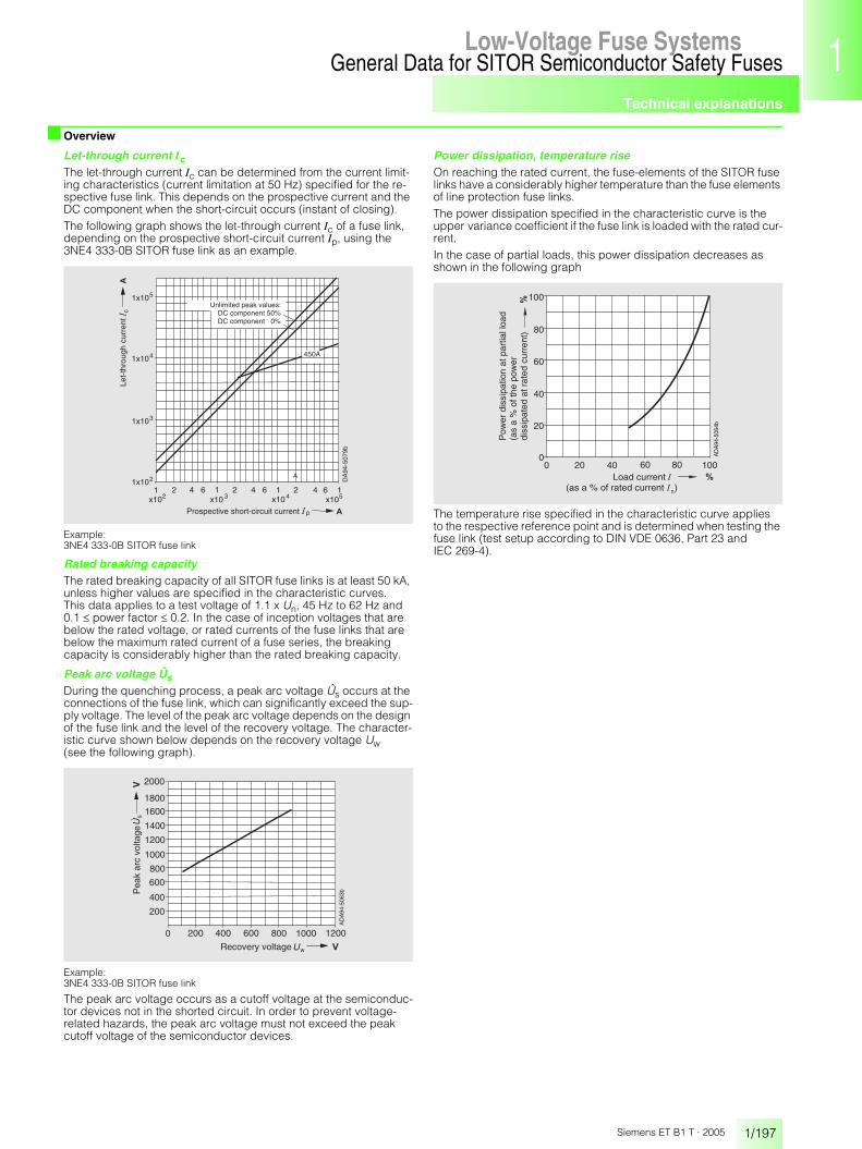
Technical explanations
1/197
General Data for SITOR Semiconductor Safety FusesLow-Voltage Fuse Systems 1
345678910
1213
Siemens ET B1 T · 2005
■ Overview
Let-through current Ic
The let-through current Ic can be determined from the current limit-ing characteristics (current limitation at 50 Hz) specified for the re-spective fuse link. This depends on the prospective current and the DC component when the short-circuit occurs (instant of closing).The following graph shows the let-through current Ic of a fuse link, depending on the prospective short-circuit current Ip, using the 3NE4 333-0B SITOR fuse link as an example.
Example: 3NE4 333-0B SITOR fuse link
Rated breaking capacityThe rated breaking capacity of all SITOR fuse links is at least 50 kA, unless higher values are specified in the characteristic curves. This data applies to a test voltage of 1.1 x Un, 45 Hz to 62 Hz and 0.1 � power factor � 0.2. In the case of inception voltages that are below the rated voltage, or rated currents of the fuse links that are below the maximum rated current of a fuse series, the breaking capacity is considerably higher than the rated breaking capacity.
Peak arc voltage Ûs
During the quenching process, a peak arc voltage Ûs occurs at the connections of the fuse link, which can significantly exceed the sup-ply voltage. The level of the peak arc voltage depends on the design of the fuse link and the level of the recovery voltage. The character-istic curve shown below depends on the recovery voltage Uw (see the following graph).
Example: 3NE4 333-0B SITOR fuse link
The peak arc voltage occurs as a cutoff voltage at the semiconduc-tor devices not in the shorted circuit. In order to prevent voltage-related hazards, the peak arc voltage must not exceed the peak cutoff voltage of the semiconductor devices.
Power dissipation, temperature riseOn reaching the rated current, the fuse-elements of the SITOR fuse links have a considerably higher temperature than the fuse elements of line protection fuse links. The power dissipation specified in the characteristic curve is the upper variance coefficient if the fuse link is loaded with the rated cur-rent. In the case of partial loads, this power dissipation decreases as shown in the following graph
The temperature rise specified in the characteristic curve applies to the respective reference point and is determined when testing the fuse link (test setup according to DIN VDE 0636, Part 23 and IEC 269-4).
2
�
c
x102 x103 x104 x1052 2 4 61 1 1 1
�
4 6 4 6
1x10⁵
1x10⁴
1x10³
1x10²
450A
DA
94-5
079b
Prospective short-circuit current
Unlimited peak values:DC component 50%DC component 0%
Let-
thro
ugh
curr
ent
A
p
0 200 400 600
�
800 1000 1200
1000
1400
2000
s�
w
200
400
600
800
1200
1600
1800
Recovery voltage
Pea
k ar
c vo
ltage
AD
A94
-506
3b
100
80
60
40
20
0
�
0 20 40 60 80 100�
n
Load current(as a % of rated current )
Pow
er d
issi
patio
n at
par
tial l
oad
(as
a %
of t
he p
ower
diss
ipat
ed a
t rat
ed c
urre
nt)
AD
A94
-506
4b

Technical explanations
1/198
General Data for SITOR Semiconductor Safety FusesLow-Voltage Fuse Systems
Siemens ET B1 T · 2005
■ Overview
Parallel and series connection of fuse links
Parallel connectionIf an arm of a converter connection has several semiconductor de-vices so that the fuse links are connected in parallel, only the fuse link connected in series to the faulty semiconductor device is tripped in the event of an internal short-circuit. It must quench the full supply voltage.To boost the voltage, two or more parallel fuse links can be assigned to a single semiconductor device without reducing the current. The resulting breaking I2t value increases with the square of the number of parallel connections. In this case, in order to prevent incorrect dis-tribution of the current, you should only use fuse links of the same type.
Series connectionThere are two kinds of series connection available:• series connection in the converter arm• 2 fused converter arms through which a short-circuit current flows
in seriesIn both cases, uniform voltage sharing can only be assumed if the melting time of the SITOR fuse link does not exceed the value specified in the following table.
Cooling conditions for series-connected fuse links should be ap-proximately the same. If faults are expected, during which the spec-ified melting times are exceeded (as a result of a slower current rise), it can no longer be assumed that voltage sharing is uniform. The volt-age of the fuse links must then be rated so that a single fuse link can quench the full supply voltage.It is best to avoid the series connection of fuse links in a converter connection arm and instead use a single fuse link with a suitably high rated voltage.
Use with direct currentFor fuse links that are to be used in DC circuits, some data may vary from the data specified in the characteristic curves for alternating current.
Permissible direct voltageThe permissible direct voltage Uperm of the fuse links depends on the rated voltage Un, of the time constants � = L/R in the DC circuit and on the prospective current Ip. The permissible direct voltage refers to the rated voltage Un and is specified depending on the time constants �, the prospective current is a parameter (see the follow-ing graphs).
with the exception of series 3NE1 0.., 3NE1 8..
with the exception of series 3NE1 0.., 3NE1 8..
Breaking I2t value I2tAThe breaking I2t value I2tA depends on the voltage, on the time con-stants � = L/R and on the prospective current Ip. It is calculated from the I2tA value specified in the characteristic curve of the respective fuse link at rated voltage Un and correction factor kA, whereby, in-stead of the recovery voltage Uw, the direct voltage is used against which the fuse link is to switch. The breaking I2t value determined in this way applies under the following conditions: • time constant L/R � 25 ms for Ip � 20 x In• time constant L/R � 10 ms for Ip = 10 x In • the breaking I2t values increase by 20 % • for Ip � 20 x In and time constant L/R = 60 ms• for Ip = 10 x In and time constant L/R = 35 ms
SITOR fuse links Maximum melting time for uniform voltage sharing
Type ms
3NC1 0..3NC1 1..3NC1 4..3NC1 5..3NC2 2..
10
3NC2 4..3NC5 8..3NC7 3..3NC8 4..
4010
3NE1 0..3NE1 2..3NE1 3..3NE1 4..3NE1 8..
10
2010
3NE3 2..3NE3 3..3NE3 4..3NE3 5..3NE3 6..
10
20
3NE4 1..3NE4 3..
10
3NE5 4..3NE5 6..
20
3NE6 4.. 10
3NE7 4..3NE7 6..
20
3NE8 0..3NE8 7..
10
3NE9 4..3NE9 6..
1020
0 10 20 30 40 50 60 70 80� �
p n
> 20 �
p n = 10
p n = 5
nperm
Time constant � � � =
1.00
0.90
0.80
0.70
0.60
0.50
0.40 AD
A94
-506
5b
perm
. DC
vol
tage
rate
d vo
ltage
0 10 20 30 40 50 60 70 80� �
p n
> 20 �
p n = 10
p n = 5
Time constant
0.90
0.80
0.70
0.60
0.50
0.40
0.30
perm
. DC
vol
tage
rate
d vo
ltage
perm
n
AD
A94
-506
6b

Technical explanations
1/199
General Data for SITOR Semiconductor Safety FusesLow-Voltage Fuse Systems 1
345678910
1213
Siemens ET B1 T · 2005
■ Overview
Peak arc voltage Ûs
The peak arc voltage Ûs is determined from the curve specified in the characteristics for the respective fuse link, whereby instead of the recovery voltage Uw, the direct voltage is used against which the fuse link is to switch. The peak arc voltage determined in this way applies under the fol-lowing conditions: • time constant L/R � 20 ms for Ip � 20 x In• time constant L/R � 35 ms for Ip 10 x InThe switching voltages increase by 20% • for Ip � 20 x In and time constant L/R = 45 ms• for Ip 10 x In and time constant L/R = 60 ms
IndicatorAn indicator shows the switching of the fuse link. The indicator of the SITOR fuse links has a transformer operating voltage between 20 V (Un � 1000 V) and 40 V (Un > 1000 V).
Accessories
Fuse bases, fuse pullersSome of the SITOR fuse links can be inserted in matching fuse bases. The matching fuse bases (single-pole and three-pole) and the respective fuse pullers are listed in the technical specifications, from page 1/83.NoteEven if the values of the rated voltage and/or current of the fuse bases are lower than that of the allocated fuse link, the values of the fuse link apply.
Fuse switch disconnectors, switch disconnectors with fusesSome series of SITOR fuse links are suitable for operation in fuse switch disconnectors 3NP4 and 3NP5 or in switch disconnectors with fuses 3KL and 3KM (see catalogs LV 10 and LV 30). When using switch disconnectors, the following points must be observed: • Because, compared to LV HRC fuses, the power dissipation of the
SITOR fuse links is higher, the permissible load current of the fuse links sometimes needs to be reduced, see below (Configuration manual).
• Fuse links with rated currents In > 63 A may also not be used for overload protection when they have utilization category gR.
NoteAll fuse links of the series 3NE1 ... with rated currents In from 16 A to 850 A and utilization categories gR or gS can be used for overload protection. • The rated voltage and rated isolation voltage of the switch discon-
nectors must at least correspond to the available voltage. • However, when using fuse links of the series 3NE3 2.., 3NE3 3..,
3NE4 3.., 3NC2 4.. and 3NC8 4.., the switching capacity of the fuse switch disconnectors must not be fully utilized due to the slot-ted blade. Occasional switching of currents up to the rated current of the fuse link is permissible
• Fuse links of the series 3NE4 1.., when used in fuse switch discon-nectors, may only be occasionally switched, and only without load, as this places the fuse blade under great mechanical stress.
In the technical specifications, from page 1/83, the switch discon-nectors are allocated to their respective individual fuse links. The permissible load of the fuse link and the required conductor cross-section can be found in the configuration manual "Configuring SITOR", Order No.: E20001-A700-P302.
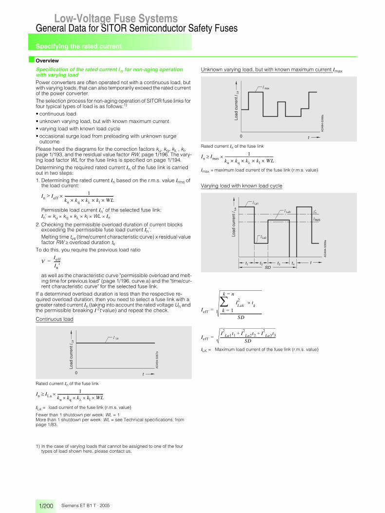
Specifying the rated current
1/200
General Data for SITOR Semiconductor Safety FusesLow-Voltage Fuse Systems
Siemens ET B1 T · 2005
■ Overview
Specification of the rated current In for non-aging operation with varying loadPower converters are often operated not with a continuous load, but with varying loads, that can also temporarily exceed the rated current of the power converter. The selection process for non-aging operation of SITOR fuse links for four typical types of load is as follows:1) • continuous load • unknown varying load, but with known maximum current • varying load with known load cycle • occasional surge load from preloading with unknown surge
outcome Please heed the diagrams for the correction factors ku, kq, k� , kl, page 1/193, and the residual value factor RW, page 1/196. The vary-ing load factor WL for the fuse links is specified on page 1/194. Determining the required rated current In of the fuse link is carried out in two steps: 1. Determining the rated current In based on the r.m.s. value Irms of
the load current:
Permissible load current In’ of the selected fuse link: In’ = ku � kq � k� � kl � WL � In
2. Checking the permissible overload duration of current blocks exceeding the permissible fuse load current In’. Melting time tvs (time/current characteristic curve) x residual value factor RW � overload duration tk
To do this, you require the previous load ratio
as well as the characteristic curve "permissible overload and melt-ing time for previous load" (page 1/196, curve a) and the "time/cur-rent characteristic curve" for the selected fuse link.
If a determined overload duration is less than the respective re-quired overload duration, then you need to select a fuse link with a greater rated current In (taking into account the rated voltage Un and the permissible breaking I 2t value) and repeat the check.
Continuous load
Rated current In of the fuse link
ILa = load current of the fuse link (r.m.s. value)
Fewer than 1 shutdown per week: WL = 1More than 1 shutdown per week: WL = see Technical specifications, from page 1/83.
1) In the case of varying loads that cannot be assigned to one of the four types of load shown here, please contact us.
Unknown varying load, but with known maximum current Imax
Rated current In of the fuse link
Imax = maximum load current of the fuse link (r.m.s. value)
Varying load with known load cycle
ILK = Maximum load current of the fuse link (r.m.s. value)
I� I����
k k k� k� WL��������������������������������������������������������
VI���I� ��������
La
0
LaLo
ad c
urre
nt
AD
A94
-506
7a
I� I ��
k k� k�� k� WL���������������������������������������������������������
max
0
LaLo
ad c
urre
nt
AD
A94
-506
8a
I� I����
k k k� k� WL����������������������������������������
La1
La3
La2
'n
1 2 3 4
La
RMS
Load
cur
rent
AD
A94
-506
9a
I���
I�
Laktk
�
�k ��
��k n�
�SD
��������������������������������������������
I���I�
La�t� I�
La�t� I�
La�t�� �
SD�����������������������������������������������������������������

Specifying the rated current
1/201
General Data for SITOR Semiconductor Safety FusesLow-Voltage Fuse Systems 1
345678910
1213
Siemens ET B1 T · 2005
■ Overview
Occasional surge load from preloading with unknown surge outcomeDetermining the required rated current In of the fuse link is carried out in two steps:1. Determining the rated current In based on the previous load
current Iprev:
Permissible load current In’ of the selected fuse link:In’ = ku x kq x kl x kl x WL x In
2. Checking the permissible overload duration of the surge current IsurgeMelting time tvs (time/current characteristic curve) x residual value factor RW � surge-wave duration tsurge
To do this, you require the previous load ratio
as well as the characteristic curve "permissible overload and melt-ing time for previous load" (page 1/196, curve a or b) and the "time/current characteristic curve" for the selected fuse link.
If the determined overload duration is less than the required over-load duration tsurge then you need to select a fuse link with a greater rated current In (taking into account the rated voltage Un and the permissible breaking I 2t value) and repeat the check.
Condition:tinterval � 3 x tsurge tinterval � 5 min
Sample selectionsFor a converter assembly in circuit (B6) A (B6) C, whose rated direct current is Idn = 850 A, fuse links that can be installed as arm fuses should be selected. The choice of fuse is shown for different duty types of the converter assembly. Data for converter assembly• supply voltage
UN = 3 AC 50 Hz 400 V • recovery voltage
UW = 360 V = UN x 0.9 (for shoot-throughs) • thyristor T 508N (from eupec),
l2t value� i2 dt = 320 x 10 3A2s (10 ms, cold)
• fuse links, natural air cooling, ambient temperature �u = +35 °C
• conductor cross-section for copper fuse link: 160 mm2 • conversion factor
direct current Id/fuse load current ILa : ILa = Id x 0.58 For the following examples, it is assumed, in the case of loads that exceed the rated direct current of the converter assembly, that the converter assembly is rated for this load.
Continuous, no-break load
Direct current Id = Idn = 850 A ILa = Id x 0.58 = 493 A Selected: 3NE3 335 SITOR fuse links (560 A/1000 V), WL = 1 breaking I 2t value I 2tA = 360 x 103 x 0.53 = 191 x 103 A2s test cross-section according to page 1/192: 400 mm2
The following correction factors are to be applied:ku = 1.02 (�u = +35 °C)kq = 0.91 (conductor cross-section, double-ended, 40 % of test cross-section)k��= 1.0 (conduction angle � = 120°)kl = 1.0 (no forced-air cooling)Required rated current In of the SITOR fuse link:
Unknown varying load, but with known maximum current
Max. direct current Idmax = 750 A Max. fuse current Imax = Idmax x 0.58 = 435 A Selected: 3NE3 334-0B SITOR fuse link (560 A/1000 V), WL = 1 breaking I 2t value I 2tA = 260 x 103 x 0.53 = 138 x 103 A2s test cross-section according to page 1/192: 400 mm2
The following correction factors are to be applied:ku = 1.02 (�u = +35 °C)kq = 0.91 (conductor cross-section, double-ended, 40 % of test cross-section)k��= 1.0 (conduction angle � = 120°)kl = 1.0 (no forced-air cooling)Required rated current In of the SITOR fuse link:
I� Iprev�
k k k� k� WL�����������������������������������������������������������
VI���I� ��������
'n
0
La
pre
interval
impulse
impulse
Load
cur
rent�
AD
A94
-507
0a
DA
94-5
071
� La493 A
I� I ��
k k� k�� k� WL����������������������������������������������������� �������
����� �� ��� � ���� � ��� � �� � ��������������������������������������������������������������������������� ��� ��
max�
DA
94-5
072
La�
= 435 A
I� I����
k k� k�� k� WL����������������������������������������������������� �������
����� �� ��� � ���� � ��� � �� � ��������������������������������������������������������������������������� ��� ��
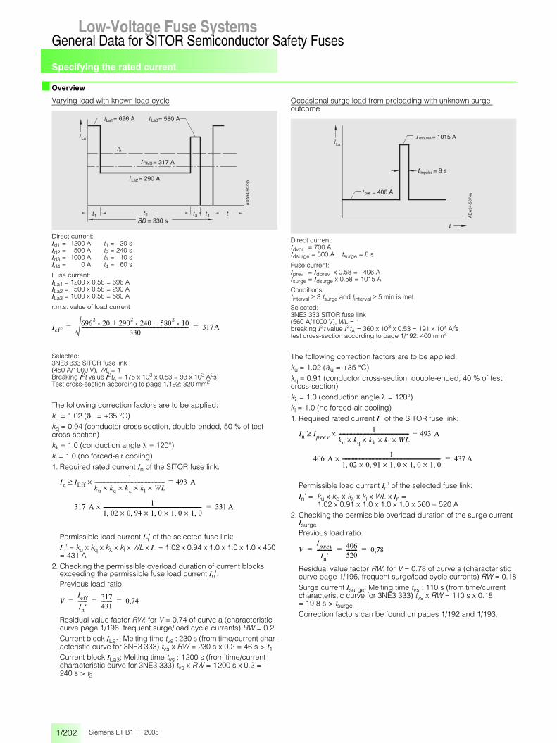
Specifying the rated current
1/202
General Data for SITOR Semiconductor Safety FusesLow-Voltage Fuse Systems
Siemens ET B1 T · 2005
■ Overview
Varying load with known load cycle
Direct current: Id1 = 1200 A t1 = 20 s Id2 = 500 A t2 = 240 s Id3 = 1000 A t3 = 10 s Id4 = 0 A t4 = 60 s
Fuse current: ILa1 = 1200 x 0.58 = 696 A ILa2 = 500 x 0.58 = 290 A ILa3 = 1000 x 0.58 = 580 A
r.m.s. value of load current
Selected: 3NE3 333 SITOR fuse link (450 A/1000 V), WL = 1 Breaking I2t value I2tA = 175 x 103 x 0.53 = 93 x 103 A2s Test cross-section according to page 1/192: 320 mm2
The following correction factors are to be applied:ku = 1.02 (�u = +35 °C)kq = 0.94 (conductor cross-section, double-ended, 50 % of test cross-section)k� = 1.0 (conduction angle � = 120°)kl = 1.0 (no forced-air cooling)1. Required rated current In of the SITOR fuse link:
Permissible load current In’ of the selected fuse link: In’ = ku x kq x k� x kl x WL x In = 1.02 x 0.94 x 1.0 x 1.0 x 1.0 x 450 = 431 A
2. Checking the permissible overload duration of current blocks exceeding the permissible fuse load current In’.Previous load ratio:
Residual value factor RW: for V = 0.74 of curve a (characteristic curve page 1/196, frequent surge/load cycle currents) RW = 0.2Current block ILa1: Melting time tvs : 230 s (from time/current char-acteristic curve for 3NE3 333) tvs x RW = 230 s x 0.2 = 46 s > t1Current block ILa3: Melting time tvs : 1200 s (from time/current characteristic curve for 3NE3 333) tvs x RW = 1200 s x 0.2 = 240 s > t3
Occasional surge load from preloading with unknown surge outcome
Direct current: Idvor = 700 A Idsurge = 500 A tsurge = 8 s
Fuse current: Iprev = Idprev x 0.58 = 406 A Isurge = Idsurge x 0.58 = 1015 A
Conditions tinterval � 3 tsurge and tinterval � 5 min is met.
Selected: 3NE3 333 SITOR fuse link (560 A/1000 V), WL = 1 breaking I2t value I2tA = 360 x 103 x 0.53 = 191 x 103 A2s test cross-section according to page 1/192: 400 mm2
The following correction factors are to be applied:ku = 1.02 (�u = +35 °C)kq = 0.91 (conductor cross-section, double-ended, 40 % of test cross-section)k��= 1.0 (conduction angle � = 120°)kl = 1.0 (no forced-air cooling)1. Required rated current In of the SITOR fuse link:
Permissible load current In’ of the selected fuse link: In’ = ku x kq x k� x kl x WL x In =
1.02 x 0.91 x 1.0 x 1.0 x 1.0 x 560 = 520 A2. Checking the permissible overload duration of the surge current
IsurgePrevious load ratio:
Residual value factor RW: for V = 0.78 of curve a (characteristic curve page 1/196, frequent surge/load cycle currents) RW = 0.18Surge current Isurge: Melting time tvs : 110 s (from time/current characteristic curve for 3NE3 333) tvs x RW = 110 s x 0.18 = 19.8 s > tsurge
Correction factors can be found on pages 1/192 and 1/193.
La1
n
1 2 4
= 330 s
La
= 696 A La3= 580 A
= 317 A
3
La2= 290 A
'
RMS
AD
A94
-507
3a
I������� �� ������ ��� ���� �����
������������������������������������������������������������������������������� ����� �
I� I����
k k� k�� k� WL����������������������������������������������������� �������
����� �� ��� � ���� � ��� � �� � ��������������������������������������������������������������������������� ��� ��
VI���I� ������� ���
����������� � ���� � �
La
= 406 A
= 1015 A
= 8 s
pre
impulse
impulse
AD
A94
-507
4a
I� Iprev�
k k� k�� k� WL����������������������������������������������������� �������
����� �� ��� � ���� � ��� � �� � ��������������������������������������������������������������������������� ��� ��
VIprev
I� ����������� ���
����������� � ���� � �
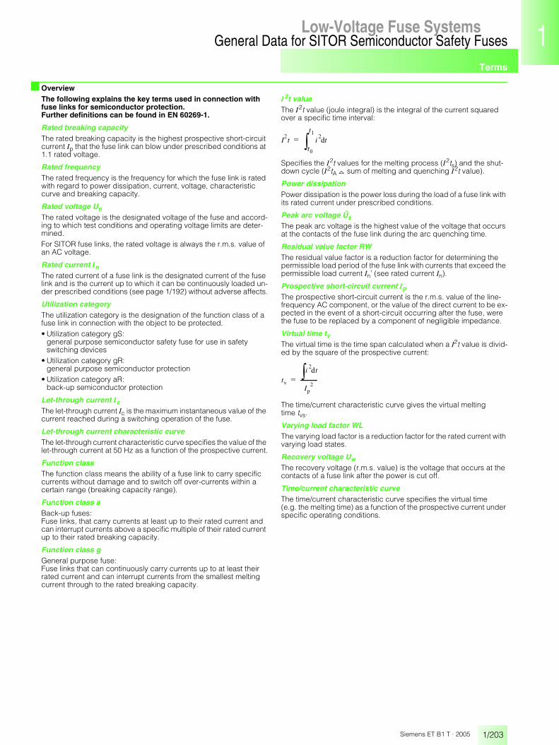
Terms
1/203
General Data for SITOR Semiconductor Safety FusesLow-Voltage Fuse Systems 1
345678910
1213
Siemens ET B1 T · 2005
■ OverviewThe following explains the key terms used in connection with fuse links for semiconductor protection.Further definitions can be found in EN 60269-1.
Rated breaking capacityThe rated breaking capacity is the highest prospective short-circuit current Ip that the fuse link can blow under prescribed conditions at 1.1 rated voltage.
Rated frequencyThe rated frequency is the frequency for which the fuse link is rated with regard to power dissipation, current, voltage, characteristic curve and breaking capacity.
Rated voltage Un
The rated voltage is the designated voltage of the fuse and accord-ing to which test conditions and operating voltage limits are deter-mined.For SITOR fuse links, the rated voltage is always the r.m.s. value of an AC voltage.
Rated current In
The rated current of a fuse link is the designated current of the fuse link and is the current up to which it can be continuously loaded un-der prescribed conditions (see page 1/192) without adverse affects.
Utilization categoryThe utilization category is the designation of the function class of a fuse link in connection with the object to be protected.• Utilization category gS:
general purpose semiconductor safety fuse for use in safety switching devices
• Utilization category gR: general purpose semiconductor protection
• Utilization category aR: back-up semiconductor protection
Let-through current Ic
The let-through current Ic is the maximum instantaneous value of the current reached during a switching operation of the fuse.
Let-through current characteristic curveThe let-through current characteristic curve specifies the value of the let-through current at 50 Hz as a function of the prospective current.
Function classThe function class means the ability of a fuse link to carry specific currents without damage and to switch off over-currents within a certain range (breaking capacity range).
Function class aBack-up fuses:Fuse links, that carry currents at least up to their rated current and can interrupt currents above a specific multiple of their rated current up to their rated breaking capacity.
Function class gGeneral purpose fuse:Fuse links that can continuously carry currents up to at least their rated current and can interrupt currents from the smallest melting current through to the rated breaking capacity.
I2t valueThe I2t value (joule integral) is the integral of the current squared over a specific time interval:
Specifies the I2t values for the melting process (I2ts) and the shut-down cycle (I2tA _ sum of melting and quenching I2t value).
Power dissipationPower dissipation is the power loss during the load of a fuse link with its rated current under prescribed conditions.
Peak arc voltage Ûs
The peak arc voltage is the highest value of the voltage that occurs at the contacts of the fuse link during the arc quenching time.
Residual value factor RWThe residual value factor is a reduction factor for determining the permissible load period of the fuse link with currents that exceed the permissible load current In’ (see rated current In).
Prospective short-circuit current Ip
The prospective short-circuit current is the r.m.s. value of the line-frequency AC component, or the value of the direct current to be ex-pected in the event of a short-circuit occurring after the fuse, were the fuse to be replaced by a component of negligible impedance.
Virtual time tvThe virtual time is the time span calculated when a I2t value is divid-ed by the square of the prospective current:
The time/current characteristic curve gives the virtual meltingtime tvs.
Varying load factor WLThe varying load factor is a reduction factor for the rated current with varying load states.
Recovery voltage Uw
The recovery voltage (r.m.s. value) is the voltage that occurs at the contacts of a fuse link after the power is cut off.
Time/current characteristic curveThe time/current characteristic curve specifies the virtual time (e.g. the melting time) as a function of the prospective current under specific operating conditions.
I�t i
�t�
t�
t�
��
t�
i�� �t
I��
�������������
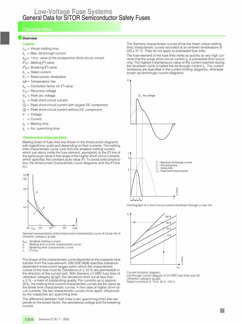
Characteristics
1/204
General Data for SITOR Semiconductor Safety FusesLow-Voltage Fuse Systems
Siemens ET B1 T · 2005
■ Overview
Legendtvs = Virtual melting timeIc = Max. let-through currentIeff = r.m.s. value of the prospective short-circuit currentI2ts= Melting I2t valueI2ta= Breaking-I2t valueIn = Rated currentPv = Rated power dissipation�� = Temperature riseka = Correction factor for I2t valueUw= Recovery voltageÛs = Peak arc voltageip = Peak short-circuit current$ = Peak short-circuit current with largest DC component% = Peak short-circuit current without DC componentU = Voltagei = Currentts = Melting timetL = Arc quenching time
Time/current characteristicsMelting times of fuse links are shown in the time/current diagrams with logarithmic scale and depending on their currents. The melting time characteristic curve runs from the smallest melting current, which just about melts the fuse element, asymptotic to the I2t line of the same joule value in the range of the higher short-circuit currents, which specifies the constant joule value I2t. To avoid overcomplica-tion, the time/current characteristic curve diagrams omit the I2t-line (c).
General representation of the time/current characteristic curve of a fuse link of utilization category gL/gG
Imin : Smallest melting currenta : Melting time-current characteristic curveb : Breaking time characteristic curvec : I2t line
The shape of the characteristic curve depends on the outwards heat transfer from the fuse-element. DIN VDE 0636 specifies tolerance-dependent time/current ranges within which the characteristic curves of the fuse must lie. Deviations of ± 10 % are permissible in the direction of the current axis. With Siemens LV HRC fuse links of utilization category gL/gG, the deviations work out at less than ± 5 % - a mark of outstanding quality. For currents up to approx. 20 In, the melting time-current characteristic curves are the same as the break time characteristic curves. In the case of higher short-cir-cuit currents, the two characteristic curves move apart, influenced by the respective arc quenching time. The difference between both lines (=arc quenching time) also de-pends on the power factor, the operational voltage and the breaking current.
The Siemens characteristic curves show the mean virtual melting time characteristic curves recorded at an ambient temperature of (20 ± 5) °C. They do not apply to preloaded fuse links.The fuse-element of the fuse links melts so quickly at very high cur-rents that the surge short-circuit current Ip is prevented from occur-ring. The highest instantaneous value of the current reached during the shutdown cycle is called the let-through current Ic. The current limitations are specified in the current limiting diagrams, otherwise known as let-through current diagrams.
Oscillograph of a short-circuit current shutdown through a fuse link
Current limitation diagram; Let-through current diagram of LV HRC fuse links size 00, Utilization category gL/gG,Rated currents 6 A, 10 A, 50 A, 100 A
I2_0
6996
a
10 10 10 10 � [A]
10
10
10[s]
a
b
c
� min
9
5
1
1 2 3 4
�
I2_0
6997
b
�
� P
c
s L
Ûs : Arc voltage
Maximum let-through currentPre-arcing timeArcing timePeak short-circuit current
�
�
�
�
c
s
L
P
�
��
I2_0
6998
a
�
100 A�
50 A
10 A
6 A
c
eff
7